EP3588247A1 - Information processing device, information processing method, and program - Google Patents
Information processing device, information processing method, and program Download PDFInfo
- Publication number
- EP3588247A1 EP3588247A1 EP17897499.4A EP17897499A EP3588247A1 EP 3588247 A1 EP3588247 A1 EP 3588247A1 EP 17897499 A EP17897499 A EP 17897499A EP 3588247 A1 EP3588247 A1 EP 3588247A1
- Authority
- EP
- European Patent Office
- Prior art keywords
- irradiation
- detection unit
- person
- information processing
- processing apparatus
- Prior art date
- Legal status (The legal status is an assumption and is not a legal conclusion. Google has not performed a legal analysis and makes no representation as to the accuracy of the status listed.)
- Granted
Links
Images



Classifications
-
- G—PHYSICS
- G03—PHOTOGRAPHY; CINEMATOGRAPHY; ANALOGOUS TECHNIQUES USING WAVES OTHER THAN OPTICAL WAVES; ELECTROGRAPHY; HOLOGRAPHY
- G03B—APPARATUS OR ARRANGEMENTS FOR TAKING PHOTOGRAPHS OR FOR PROJECTING OR VIEWING THEM; APPARATUS OR ARRANGEMENTS EMPLOYING ANALOGOUS TECHNIQUES USING WAVES OTHER THAN OPTICAL WAVES; ACCESSORIES THEREFOR
- G03B21/00—Projectors or projection-type viewers; Accessories therefor
- G03B21/14—Details
-
- G—PHYSICS
- G03—PHOTOGRAPHY; CINEMATOGRAPHY; ANALOGOUS TECHNIQUES USING WAVES OTHER THAN OPTICAL WAVES; ELECTROGRAPHY; HOLOGRAPHY
- G03B—APPARATUS OR ARRANGEMENTS FOR TAKING PHOTOGRAPHS OR FOR PROJECTING OR VIEWING THEM; APPARATUS OR ARRANGEMENTS EMPLOYING ANALOGOUS TECHNIQUES USING WAVES OTHER THAN OPTICAL WAVES; ACCESSORIES THEREFOR
- G03B17/00—Details of cameras or camera bodies; Accessories therefor
- G03B17/48—Details of cameras or camera bodies; Accessories therefor adapted for combination with other photographic or optical apparatus
- G03B17/54—Details of cameras or camera bodies; Accessories therefor adapted for combination with other photographic or optical apparatus with projector
-
- G—PHYSICS
- G06—COMPUTING OR CALCULATING; COUNTING
- G06F—ELECTRIC DIGITAL DATA PROCESSING
- G06F3/00—Input arrangements for transferring data to be processed into a form capable of being handled by the computer; Output arrangements for transferring data from processing unit to output unit, e.g. interface arrangements
- G06F3/01—Input arrangements or combined input and output arrangements for interaction between user and computer
-
- G—PHYSICS
- G06—COMPUTING OR CALCULATING; COUNTING
- G06F—ELECTRIC DIGITAL DATA PROCESSING
- G06F3/00—Input arrangements for transferring data to be processed into a form capable of being handled by the computer; Output arrangements for transferring data from processing unit to output unit, e.g. interface arrangements
- G06F3/01—Input arrangements or combined input and output arrangements for interaction between user and computer
- G06F3/011—Arrangements for interaction with the human body, e.g. for user immersion in virtual reality
-
- G—PHYSICS
- G06—COMPUTING OR CALCULATING; COUNTING
- G06F—ELECTRIC DIGITAL DATA PROCESSING
- G06F3/00—Input arrangements for transferring data to be processed into a form capable of being handled by the computer; Output arrangements for transferring data from processing unit to output unit, e.g. interface arrangements
- G06F3/01—Input arrangements or combined input and output arrangements for interaction between user and computer
- G06F3/011—Arrangements for interaction with the human body, e.g. for user immersion in virtual reality
- G06F3/012—Head tracking input arrangements
-
- G—PHYSICS
- G06—COMPUTING OR CALCULATING; COUNTING
- G06F—ELECTRIC DIGITAL DATA PROCESSING
- G06F3/00—Input arrangements for transferring data to be processed into a form capable of being handled by the computer; Output arrangements for transferring data from processing unit to output unit, e.g. interface arrangements
- G06F3/01—Input arrangements or combined input and output arrangements for interaction between user and computer
- G06F3/011—Arrangements for interaction with the human body, e.g. for user immersion in virtual reality
- G06F3/013—Eye tracking input arrangements
-
- G—PHYSICS
- G06—COMPUTING OR CALCULATING; COUNTING
- G06F—ELECTRIC DIGITAL DATA PROCESSING
- G06F3/00—Input arrangements for transferring data to be processed into a form capable of being handled by the computer; Output arrangements for transferring data from processing unit to output unit, e.g. interface arrangements
- G06F3/01—Input arrangements or combined input and output arrangements for interaction between user and computer
- G06F3/017—Gesture based interaction, e.g. based on a set of recognized hand gestures
-
- G—PHYSICS
- G06—COMPUTING OR CALCULATING; COUNTING
- G06F—ELECTRIC DIGITAL DATA PROCESSING
- G06F3/00—Input arrangements for transferring data to be processed into a form capable of being handled by the computer; Output arrangements for transferring data from processing unit to output unit, e.g. interface arrangements
- G06F3/01—Input arrangements or combined input and output arrangements for interaction between user and computer
- G06F3/03—Arrangements for converting the position or the displacement of a member into a coded form
- G06F3/0304—Detection arrangements using opto-electronic means
-
- G—PHYSICS
- G06—COMPUTING OR CALCULATING; COUNTING
- G06T—IMAGE DATA PROCESSING OR GENERATION, IN GENERAL
- G06T7/00—Image analysis
-
- G—PHYSICS
- G06—COMPUTING OR CALCULATING; COUNTING
- G06T—IMAGE DATA PROCESSING OR GENERATION, IN GENERAL
- G06T7/00—Image analysis
- G06T7/70—Determining position or orientation of objects or cameras
-
- G—PHYSICS
- G09—EDUCATION; CRYPTOGRAPHY; DISPLAY; ADVERTISING; SEALS
- G09G—ARRANGEMENTS OR CIRCUITS FOR CONTROL OF INDICATING DEVICES USING STATIC MEANS TO PRESENT VARIABLE INFORMATION
- G09G5/00—Control arrangements or circuits for visual indicators common to cathode-ray tube indicators and other visual indicators
-
- G—PHYSICS
- G09—EDUCATION; CRYPTOGRAPHY; DISPLAY; ADVERTISING; SEALS
- G09G—ARRANGEMENTS OR CIRCUITS FOR CONTROL OF INDICATING DEVICES USING STATIC MEANS TO PRESENT VARIABLE INFORMATION
- G09G5/00—Control arrangements or circuits for visual indicators common to cathode-ray tube indicators and other visual indicators
- G09G5/36—Control arrangements or circuits for visual indicators common to cathode-ray tube indicators and other visual indicators characterised by the display of a graphic pattern, e.g. using an all-points-addressable [APA] memory
-
- H—ELECTRICITY
- H04—ELECTRIC COMMUNICATION TECHNIQUE
- H04N—PICTORIAL COMMUNICATION, e.g. TELEVISION
- H04N9/00—Details of colour television systems
- H04N9/12—Picture reproducers
- H04N9/31—Projection devices for colour picture display, e.g. using electronic spatial light modulators [ESLM]
- H04N9/3179—Video signal processing therefor
-
- H—ELECTRICITY
- H04—ELECTRIC COMMUNICATION TECHNIQUE
- H04N—PICTORIAL COMMUNICATION, e.g. TELEVISION
- H04N9/00—Details of colour television systems
- H04N9/12—Picture reproducers
- H04N9/31—Projection devices for colour picture display, e.g. using electronic spatial light modulators [ESLM]
- H04N9/3191—Testing thereof
- H04N9/3194—Testing thereof including sensor feedback
-
- G—PHYSICS
- G09—EDUCATION; CRYPTOGRAPHY; DISPLAY; ADVERTISING; SEALS
- G09G—ARRANGEMENTS OR CIRCUITS FOR CONTROL OF INDICATING DEVICES USING STATIC MEANS TO PRESENT VARIABLE INFORMATION
- G09G2340/00—Aspects of display data processing
- G09G2340/04—Changes in size, position or resolution of an image
- G09G2340/0464—Positioning
-
- G—PHYSICS
- G09—EDUCATION; CRYPTOGRAPHY; DISPLAY; ADVERTISING; SEALS
- G09G—ARRANGEMENTS OR CIRCUITS FOR CONTROL OF INDICATING DEVICES USING STATIC MEANS TO PRESENT VARIABLE INFORMATION
- G09G2354/00—Aspects of interface with display user
Definitions
- the present disclosure relates to an information processing apparatus, an information processing method, and a program.
- Patent Document 1 discloses a projection apparatus including an irradiation unit that can irradiate various image information.
- Patent Document 1 Japanese Patent Application Laid-Open No. 2003-044839
- Such a projection apparatus has been required to have a technology that allows a user to view the image information more comfortably.
- the present disclosure proposes a new and improved information processing apparatus that allows a user to view image information more comfortably.
- the present disclosure provides an information processing apparatus including a control unit that controls a person detection unit on the basis of an irradiation direction in which an irradiation unit capable of irradiating various image information irradiates the image information, the person detection unit forming a detection area in a direction opposite to the irradiation direction.
- the present disclosure further provides an information processing method including a control unit controlling a person detection unit on the basis of an irradiation direction in which an irradiation unit capable of irradiating various image information irradiates the image information, the person detection unit forming a detection area in a direction opposite to the irradiation direction.
- the present disclosure further provides a program that causes a computer to implement a control function that controls a person detection unit on the basis of an irradiation direction in which an irradiation unit capable of irradiating various image information irradiates the image information, the person detection unit forming a detection area in a direction opposite to the irradiation direction.
- the person detection unit is controlled on the basis of the irradiation direction so that an operation unintended by a user is less likely to be performed.
- the user can thus view the image information more comfortably.
- the above effect is not necessarily restrictive, but any of the effects illustrated in the present specification or other effects that can be perceived from the present specification may be achieved together with the above effect or in place of the above effect.
- the information processing apparatus 10 includes an irradiation unit 11, a person detection unit 12, a position detection unit 13, an attitude detection unit 14, a distance detection unit 15, an operation unit 16, a communication unit 17, and a control unit 18.
- the information processing apparatus 10 is a projection apparatus, for example.
- the information processing apparatus 10 includes the configuration of hardware such as a central processing unit (CPU), a read only memory (ROM), a random access memory (RAM), a non-volatile memory, an irradiation device, a person detection device, a position detection device, an attitude detection device, a distance detection device, an operation button, and a communication device.
- Information necessary for the operation of the information processing apparatus 10 such as a program is recorded in the ROM.
- the CPU reads and executes the program recorded in the ROM.
- the irradiation unit 11, the person detection unit 12, the position detection unit 13, the attitude detection unit 14, the operation unit 16, the communication unit 17, and the control unit 18 are implemented.
- the irradiation unit 11 includes the irradiation device, for example, and irradiates various image information within an irradiation area 11A as illustrated in Fig. 2 .
- the irradiation unit 11 irradiates the image information on a horizontal surface 100.
- a surface where the irradiation area 11A and the horizontal surface 100 intersect is an irradiation surface 11B.
- the image information is displayed on the irradiation surface 11B.
- the horizontal surface 100 includes, for example, a table top of a desk or the like, a floor, or the like.
- An optical axis of the irradiation unit 11 (that is, a central axis of the irradiation area 11A) is slightly tiled toward an outer wall surface of the information processing apparatus 10 from a direction perpendicular to the outer wall surface.
- the direction of the optical axis that is, an irradiation direction
- the irradiation direction includes a downward direction illustrated in Fig. 2 or an upward direction illustrated in Fig. 3 , for example.
- the downward direction is a direction below a horizontal direction
- the upward direction is a direction above the horizontal direction. In a case where the irradiation direction is the upward direction as illustrated in Fig.
- the irradiation unit 11 irradiates the image information on a vertical surface 200, for example.
- the information processing apparatus 10 is placed on a horizontal surface 300.
- a surface where the irradiation area 11A and the vertical surface 200 intersect is the irradiation surface 11B.
- the image information is displayed on the irradiation surface 11B.
- the vertical surface 200 includes, for example, a wall surface, a side surface of various objects, or the like.
- a user (a person U illustrated in Fig. 2 ) can display the image information on the horizontal surface 100 by placing the information processing apparatus 10 on the horizontal surface 100 and setting the irradiation direction in the downward direction.
- the user can display the image information on the vertical surface 200 by placing the information processing apparatus 10 near the vertical surface 200 and setting the irradiation direction in the upward direction.
- the information processing apparatus 10 can thus display the image information at various positions desired by the user. It is needless to say that the angle between the optical axis of the irradiation unit 11 and the outer wall surface of the information processing apparatus 10 and the types of the irradiation direction are not limited to the above.
- the surface on which the image information is to be irradiated is not limited to the horizontal surface 100 and the vertical surface 200.
- the person detection unit 12 includes the person detection device, for example, and detects a person.
- the person detection device includes, for example, a human sensor, a camera, and the like.
- the human sensor detects a person by detecting heat of the person and/or a movement of the heat.
- the camera detects a person by imaging the person.
- the information processing apparatus 10 need only include either the human sensor or the camera, but may include both.
- the person detection unit 12 forms a detection area 12A in a direction opposite to the irradiation direction (that is, the optical axis of the irradiation unit 11) in which the irradiation unit 11 irradiates the image information.
- a person to be detected is, for example, the user of the information processing apparatus 10.
- the person detection unit 12 detects a person within the detection area 12A.
- An angle between an optical axis of the detection area 12A (that is, a central axis of the detection area 12A) and the optical axis of the irradiation unit 11 is larger than 90°, for example.
- the person detection unit 12 detects a person
- the person detection unit generates person detection information to that effect and outputs the information to the control unit 18.
- the control unit 18 acquires the person detection information
- the control unit causes the irradiation unit 11 to irradiate the image information.
- the person detection unit 12 is controlled on the basis of the irradiation direction of the irradiation unit 11, whereby an operation unintended by the user is less likely to be performed.
- the person detection unit 12 of the present embodiment forms the detection area 12A in the direction opposite to the irradiation direction in which the irradiation unit 11 irradiates the image information, the detection area 12A may be formed in a direction different from the irradiation direction (irradiation surface).
- the position detection unit 13 includes the position detection device, for example, and detects an object present within the irradiation area 11A of the image information.
- the position detection device includes an infrared sensor, for example.
- the position detection unit 13 is driven in conjunction with the control unit 18 and the irradiation unit 11, and detects an object present within a detection area 13A.
- the detection area 13A covers substantially an entire area of the irradiation surface 11B.
- a target to be detected by the position detection unit 13 is a hand (more specifically, a finger) of a person, for example.
- the user can perform an input operation (for example, a tap operation, a drag operation, a pinch-in/out operation, and the like) on the image information displayed on the irradiation surface 11B.
- the position detection unit 13 detects such an input operation and outputs position detection information regarding a result of the detection to the control unit 18.
- the control unit 18 performs processing based on the position detection information such as processing of changing the image information.
- the detection area 13A of the position detection unit 13 is of course not limited to the above example but may cover, for example, only a part of the irradiation surface 11B.
- the attitude detection unit 14 includes the attitude detection device, for example, and detects an attitude of the information processing apparatus 10.
- the attitude detection device includes a gyro sensor, an acceleration sensor, or the like, for example.
- the attitude detection unit 14 outputs attitude detection information regarding a result of detection to the control unit 18.
- the control unit 18 determines the irradiation direction on the basis of the attitude detection information. Then, the control unit 18 then controls the person detection unit 12 on the basis of the irradiation direction. Details of the control will be described later.
- the distance detection unit 15 includes the distance detection device, for example, and measures a distance between the information processing apparatus 10 and the irradiation surface 11B.
- the distance detection device includes a range sensor, for example.
- the range sensor measures the distance between the information processing apparatus 10 and the irradiation surface 11B using a laser, ultrasound, or the like.
- the distance detection unit 15 measures a distance from a surface of the information processing apparatus 10 facing the irradiation surface 11B to the irradiation surface 11B, the surface being one of the outer wall surfaces of the information processing apparatus.
- This distance corresponds to the length of a perpendicular drawn from the surface facing the irradiation surface 11B to a plane including the irradiation surface 11B (which is the vertical surface 200 in the example of Fig. 3 .
- the distance detection unit 15 outputs distance detection information regarding the distance detected to the control unit 18.
- the operation unit 16 includes the operation button and the like, for example, and allows an input operation by the user.
- the operation button here includes a power button, for example.
- the operation unit outputs input operation information regarding the input operation to the control unit 18.
- the control unit 18 performs processing corresponding to the input operation. For example, the control unit 18 activates the information processing apparatus 10 in a case where the user presses the power button. Moreover, the control unit 18 causes the irradiation unit 11 to stop irradiation of the image information in a case where the user presses the power button, that is, performs an irradiation stop operation, while the information processing apparatus 10 is activated.
- the control unit 18 thus causes the information processing apparatus 10 to shift to a sleep mode. Note that such a state is also referred to as a standby mode, a suspend mode, or the like.
- the control unit 18 causes the irradiation unit 11 to restart irradiation of the image information in a case where the user presses the power button, that is, performs an irradiation restart operation, during the sleep mode.
- the communication unit 17 includes the communication device, for example, and communicates with another information processing apparatus or the like. As a result, the communication unit 17 acquires various kinds of information such as the image information from the other information processing apparatuses or the like.
- the control unit 18 includes a CPU or the like, for example, and controls each component of the information processing apparatus 10. Furthermore, the control unit 18 also controls the person detection unit 12 on the basis of the irradiation direction. Furthermore, the control unit 18 performs each processing described above. Details of the processing will be described later.
- step S10 the attitude detection unit 14 detects an attitude of the information processing apparatus 10 (for example, in which direction the placement of the apparatus allows for irradiation).
- the attitude detection unit 14 outputs attitude detection information regarding a result of detection to the control unit 18.
- step S11 the control unit 18 determines the irradiation direction on the basis of the attitude detection information.
- the control unit 18 determines whether the irradiation direction is the downward direction illustrated in Fig. 2 or the upward direction illustrated in Fig. 3 .
- step S12 the control unit 18 determines whether or not the irradiation direction is the downward direction (a first direction).
- the control unit 18 proceeds to step S13 if the irradiation direction is the downward direction (the first direction), that is, the irradiation direction is horizontal to the ground, and the irradiation surface is on a desk or a floor.
- the control unit 18 proceeds to step S14 if the irradiation direction is the upward direction (a second direction different from the first direction), that is, the irradiation direction is perpendicular to the ground, and the irradiation surface is on a wall.
- step S13 the control unit 18 stops the operation of the person detection unit 12.
- the detection area 12A of the person detection unit 12 is upward as illustrated in Fig. 2 .
- a ceiling light or the like possibly enters the detection area 12A of the person detection unit 12.
- Such a light is also a source of heat. Therefore, in a case where the person detection unit 12 includes the human sensor, the light may be detected as a person by mistake.
- the person detection unit 12 outputs person detection information to the control unit 18 so that the control unit 18 causes the irradiation unit 11 to irradiate the image information.
- the irradiation unit 11 thus possibly irradiates the image information even in a case where the user does not intend to view the image information. Moreover, since the user does not intend to view the image information, an object (for example, a glass or the like) may be put on the irradiation surface 11B. In this case, the position detection unit 13 possibly detects the presence of the object and outputs position detection information to the control unit 18. The control unit 18 in this case possibly performs processing unintended by the user. For example, in a case where an icon is displayed at the position of the object, the control unit 18 possibly determines by mistake that the user has selected the icon. As a result, the information processing apparatus 10 may perform an operation unintended by the user. Thus, in the present embodiment, the control unit 18 stops the operation of the person detection unit 12 in the case where the irradiation direction is the downward direction.
- the user switches the presence or absence of irradiation by pressing the power button.
- the user turns on the power button in a case where the irradiation unit 11 does not perform irradiation of the image information (that is, during the sleep mode).
- the control unit 18 thus causes the irradiation unit 11 to restart irradiation of the image information.
- the user presses the power button again.
- the control unit 18 thus causes the irradiation unit 11 to stop the irradiation of the image information.
- the information processing apparatus 10 shifts to the sleep mode.
- the information processing apparatus 10 can thus perform processing in accordance with the intention of the user, whereby the user can view the image information more comfortably.
- the control unit 18 thereafter ends the present basic processing.
- control unit 18 determines whether or not the power button has been pressed.
- the control unit 18 proceeds to step S15 if the power button has been pressed, or ends the present basic processing if the power button has not been pressed.
- step S15 the control unit 18 determines whether or not the irradiation unit 11 is irradiating the image information.
- the control unit 18 proceeds to step S16 if the irradiation unit 11 is irradiating the image information.
- the control unit 18 proceeds to step S20 if the irradiation unit 11 is not irradiating the image information, that is, in the sleep mode.
- step S16 the control unit 18 causes the irradiation unit 11 to stop irradiation of the image information.
- the control unit 18 causes the information processing apparatus 10 to shift to the sleep mode.
- the pressing of the power button in step S14 is the irradiation stop operation.
- step S17 the control unit 18 stops the operation of the person detection unit 12.
- step S18 the control unit 18 determines whether or not a predetermined irradiation restart condition is satisfied. The control unit 18 proceeds to step S19 if the irradiation restart condition is satisfied, or returns to step S17 if the irradiation restart condition is not satisfied. In other words, the control unit 18 waits until the irradiation restart condition is satisfied.
- the irradiation restart condition is a condition that a predetermined time has elapsed since the irradiation stop operation.
- step S19 the control unit 18 restarts the operation of the person detection unit 12.
- the control unit 18 thereafter causes the irradiation unit 11 to restart irradiation of the image information in a case where the person detection unit 12 detects a person (for example, the user).
- the control unit 18 thereafter ends the present basic processing.
- the control unit 18 stops the operation of the person detection unit 12 until the predetermined irradiation restart condition is satisfied.
- the irradiation direction is the upward direction illustrated in Fig. 3 .
- the detection area 12A of the person detection unit 12 is thus oriented in a direction away from the vertical surface 200. Therefore, the person detection unit 12 can detect a person facing the vertical surface 200.
- the person detection unit 12 outputs person detection information to the control unit 18. Then, the control unit 18 then causes the irradiation unit 11 to restart irradiation of the image information on the basis of the person detection information. Therefore, the information processing apparatus 10 possibly releases the sleep mode immediately after shifting to the sleep mode.
- the above operation may not be intended by the user.
- the user often presses the power button not with the intention to cause such an operation but in order to stop the irradiation by the irradiation unit 11 for a while.
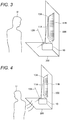
- Various cases are assumed for such a situation to occur such as a case where the user has another business to take care of. In this case, it is assumed that the user leaves the information processing apparatus 10 as illustrated in Fig. 4 .
- the control unit 18 stops the operation of the person detection unit 12 until the predetermined irradiation restart condition is satisfied. More specifically, the control unit 18 stops the operation of the person detection unit 12 until a predetermined time elapses after the irradiation stop operation is performed.
- This predetermined time is an estimated time until the user goes out of the detection area 12A of the person detection unit 12 as illustrated in Fig. 5 . Therefore, the predetermined time may be set on the basis of, for example, the size of the detection area 12A, the speed of travel (for example, an average walking speed) of the user, or the like. The predetermined time may be 10 seconds, for example.
- the control unit 18 can thus restart the operation of the person detection unit 12 after the user goes out of the detection area 12A of the person detection unit 12. In this case, since the user is outside the detection area 12A, the sleep mode is not released even if the operation of the person detection unit 12 is restarted. The user thereafter takes care of the other business and enters the detection area 12A. In response to this, the person detection unit 12 outputs person detection information to the control unit 18. The control unit 18 causes the irradiation unit 11 to restart irradiation of the image information. The information processing apparatus 10 can therefore perform processing in accordance with the intention of the user.
- the control unit 18 may cause the irradiation unit 11 to restart the irradiation in a case where the camera detects the face of the user.
- the irradiation unit 11 may restart the irradiation after it is acknowledged that the user has started viewing the image information.
- the camera and the human sensor may be used in combination.
- the control unit 18 first restarts the operation of only the human sensor in a case where the operation of the person detection unit 12 is restarted. Then, the control unit 18 also restarts the operation of the camera in a case where the human sensor detects a person.
- the control unit 18 may then cause the irradiation unit 11 to restart the irradiation in a case where the camera detects the face of the user.
- step S20 the control unit 18 causes the irradiation unit 11 to restart the irradiation of the image information.
- the pressing of the power button in step S14 is the irradiation start operation.
- the control unit 18 thereafter ends the present basic processing.
- the control unit 18 sets the aforementioned predetermined time on the basis of the distance between the information processing apparatus 10 and the irradiation surface 11B.
- Information regarding the distance is given from the distance detection unit 15.
- the following effects can be expected as a result. That is, the user in some cases wishes to view the image information at a distance from the information processing apparatus 10 because the irradiation surface 11B is large. In this case, the user is assumed to leave the information processing apparatus 10 after temporarily setting the information processing apparatus 10 to the sleep mode. Then, the distance the user moves away from the information processing apparatus 10 to an extent is assumed to be longer as the irradiation surface 11B is larger.
- the control unit 18 sets the aforementioned predetermined time on the basis of the distance between the information processing apparatus 10 and the irradiation surface 11B. Specifically, the control unit 18 sets the predetermined time to a longer time as the distance between the information processing apparatus 10 and the irradiation surface 11B is longer. As a result, the control unit 18 can restart the operation of the person detection unit 12 after the user has reached a desired position. The information processing apparatus 10 can therefore perform processing in accordance with the intention of the user.
- the control unit 18 may adjust the sensitivity of the person detection unit 12 on the basis of the distance between the information processing apparatus 10 and the irradiation surface 11B. As a result, the person detection unit 12 can detect the user more reliably even if the user is away from the information processing apparatus 10.
- the control unit 18 may cause the irradiation unit 11 to restart the irradiation in a case where the camera detects the face of the user.
- the camera and the human sensor may be used in combination. The specific processing is as described above.
- the person detection unit 12 is the camera. That is, the person detection unit 12 can detect the face of a person. Then, in step S17, the control unit 18 causes the person detection unit 12 to continue its operation. However, even if the person detection unit 12 outputs person detection information, the control unit 18 does not cause the irradiation unit 11 to restart the irradiation. Thereafter, in step S18, the control unit 18 determines whether or not an irradiation restart condition is satisfied.
- the irradiation restart condition is that the person detection unit 12 stops detecting the face of a person and then detects the face of a person again.
- the user who sets the information processing apparatus 10 to the sleep mode is assumed to turn his back on the information processing apparatus 10 and leave the information processing apparatus 10.
- the person detection unit 12 no longer detects the face of a person, that is, the face of the user.
- the person detection unit 12 again detects the face of a person, that is, the face of the user.
- the control unit 18 proceeds to step S19.
- the control unit 18 causes the irradiation unit 11 to restart irradiation of the image information.
- the information processing apparatus 10 can perform processing in accordance with the intention of the user.
- the person detection unit 12 detects the face of the user so that more accurate processing is possible.
- the person detection unit 12 is the camera. That is, the person detection unit 12 can detect a line of sight of a person. Then, in step S17, the control unit 18 causes the person detection unit 12 to continue its operation. However, even if the person detection unit 12 outputs person detection information, the control unit 18 does not cause the irradiation unit 11 to restart the irradiation. Thereafter, in step S18, the control unit 18 determines whether or not an irradiation restart condition is satisfied.
- the irradiation restart condition is that a line of sight of a person detected by the person detection unit 12 moves outside the irradiation area 11A (more specifically, the irradiation surface 11B) of the image information and then moves back to the irradiation area 11A (more specifically, the irradiation surface 11B) of the image information.
- the user who sets the information processing apparatus 10 to the sleep mode is assumed to move his line of sight away from the irradiation surface 11B.
- the person detection unit 12 detects that the line of sight of a person, that is, the line of sight of the user, has moved away from the irradiation surface 11B.
- the user thereafter moves his line of sight back to the irradiation surface 11B in a case where the user wishes to view the image information.
- the person detection unit 12 detects that the line of sight of a person, that is, the line of sight of the user, has moved back to the irradiation surface 11B.
- the control unit 18 proceeds to step S19.
- step S19 the control unit 18 causes the irradiation unit 11 to restart irradiation of the image information.
- the information processing apparatus 10 can perform processing in accordance with the intention of the user.
- the person detection unit 12 detects the line of sight of the user so that more accurate processing is possible.
- the control unit 18 controls the person detection unit 12 on the basis of the irradiation direction.
- the control unit 18 is less likely to perform an operation unintended by the user.
- the control unit 18 can perform processing more in line with the intention of the user. The user can thus view the image information more comfortably.
- the irradiation direction includes at least one of the downward direction or the upward direction so that processing in line with the intention of the user can be performed in a case where the irradiation direction corresponds with one of these directions.
- control unit 18 causes the irradiation unit 11 to irradiate the image information in a case where the person detection unit 12 detects a person or where a predetermined irradiation start operation is performed, and stops the operation of the person detection unit 12 in a case where the irradiation direction is the downward direction.
- the control unit 18 can perform processing more in line with the intention of the user.
- control unit 18 drives the position detection unit 13 in conjunction with the irradiation unit 11. Moreover, the control unit 18 then performs the aforementioned processing to be able to prevent misdetection by the position detection unit 13. As a result, the control unit 18 can perform processing more in line with the intention of the user.
- the person detection unit 12 is in some cases the human sensor that detects a person by detecting heat.
- the control unit 18 can perform processing more in line with the intention of the user.
- control unit 18 causes the irradiation unit 11 to irradiate the image information in a case where the person detection unit 12 detects a person or where a predetermined irradiation start operation is performed. Moreover, the control unit 18 also causes the irradiation unit 11 to stop the irradiation of the image information in a case where a predetermined irradiation stop operation is performed. Furthermore, in a case where the irradiation direction is the upward direction, the control unit 18 stops the operation of the person detection unit 12 until a predetermined irradiation restart condition is satisfied after the irradiation stop operation is performed. As a result, the control unit 18 can perform processing more in line with the intention of the user.
- the irradiation restart condition may be a lapse of a predetermined time since the irradiation stop operation is performed.
- the control unit 18 can perform processing more in line with the intention of the user.
- control unit 18 sets the predetermined time on the basis of the distance between the information processing apparatus 10 and the irradiation surface 11B. As a result, the control unit 18 can perform processing more in line with the intention of the user.
- the person detection unit 12 in some cases is the human sensor that detects a person by detecting heat and is sensitivity adjustable.
- the control unit 18 adjusts the sensitivity of the person detection unit 12 on the basis of the distance between the information processing apparatus 10 and the irradiation surface 11B. As a result, the control unit 18 can perform processing more in line with the intention of the user.
- the person detection unit 12 is in some cases the camera that can detect the face of a person.
- the irradiation restart condition may be that the person detection unit 12 stops detecting the face of a person and then detects the face of a person again.
- the control unit 18 can perform processing more in line with the intention of the user.
- the person detection unit 12 is in some cases the camera that can detect the line of sight of a person.
- the irradiation restart condition may be that the line of sight of a person detected by the person detection unit 12 moves outside the irradiation surface 11B and thereafter moves back to the irradiation surface 11B.
- the control unit 18 can perform processing more in line with the intention of the user.
- the control unit 18 may be performed by another information processing apparatus.
- the control unit 18 in the other information processing apparatus acquires necessary information (for example, person detection information, position detection information, attitude detection information, distance detection information, input operation information, and the like) from the information processing apparatus 10 and performs the aforementioned processing on the information processing apparatus 10.
Landscapes
- Engineering & Computer Science (AREA)
- Theoretical Computer Science (AREA)
- General Engineering & Computer Science (AREA)
- General Physics & Mathematics (AREA)
- Physics & Mathematics (AREA)
- Human Computer Interaction (AREA)
- Signal Processing (AREA)
- Multimedia (AREA)
- Computer Hardware Design (AREA)
- Computer Vision & Pattern Recognition (AREA)
- User Interface Of Digital Computer (AREA)
- Control Or Security For Electrophotography (AREA)
- Controls And Circuits For Display Device (AREA)
- Image Analysis (AREA)
- Circuit Arrangement For Electric Light Sources In General (AREA)
Abstract
Description
- The present disclosure relates to an information processing apparatus, an information processing method, and a program.
- Patent Document 1 discloses a projection apparatus including an irradiation unit that can irradiate various image information.
- Patent Document 1: Japanese Patent Application Laid-Open No.
2003-044839 - Now, such a projection apparatus has been required to have a technology that allows a user to view the image information more comfortably.
- Thus, the present disclosure proposes a new and improved information processing apparatus that allows a user to view image information more comfortably.
- The present disclosure provides an information processing apparatus including a control unit that controls a person detection unit on the basis of an irradiation direction in which an irradiation unit capable of irradiating various image information irradiates the image information, the person detection unit forming a detection area in a direction opposite to the irradiation direction.
- Furthermore, the present disclosure further provides an information processing method including a control unit controlling a person detection unit on the basis of an irradiation direction in which an irradiation unit capable of irradiating various image information irradiates the image information, the person detection unit forming a detection area in a direction opposite to the irradiation direction.
- Furthermore, the present disclosure further provides a program that causes a computer to implement a control function that controls a person detection unit on the basis of an irradiation direction in which an irradiation unit capable of irradiating various image information irradiates the image information, the person detection unit forming a detection area in a direction opposite to the irradiation direction.
- As described above, according to the present disclosure, the person detection unit is controlled on the basis of the irradiation direction so that an operation unintended by a user is less likely to be performed. The user can thus view the image information more comfortably. Note that the above effect is not necessarily restrictive, but any of the effects illustrated in the present specification or other effects that can be perceived from the present specification may be achieved together with the above effect or in place of the above effect.
-
-
Fig. 1 is a functional block diagram of an information processing apparatus according to an embodiment of the present disclosure. -
Fig. 2 is an explanatory view illustrating an example of installation of the information processing apparatus. -
Fig. 3 is an explanatory view illustrating an example of installation of the information processing apparatus. -
Fig. 4 is an explanatory view illustrating an example of use of the information processing apparatus. -
Fig. 5 is an explanatory view illustrating an example of use of the information processing apparatus. -
Fig. 6 is a flowchart illustrating the procedure of processing by the information processing apparatus. - A preferred embodiment of the present disclosure will now be described in detail with reference to the drawings. Note that in the present specification and the drawings, components having substantially the same functional configuration are assigned the same reference numeral, whereby redundant description will be omitted.
- Note that the description will be made in the following order.
- 1. Configuration of information processing apparatus
- 2. Processing by information processing apparatus
- 2-0. Basic processing
- 2-1. First modification of basic processing
- 2-2. Second modification of basic processing
- 2-3. Third modification of basic processing
- First, the configuration of an
information processing apparatus 10 according to the present embodiment will be described on the basis ofFigs. 1 to 3 . Theinformation processing apparatus 10 includes anirradiation unit 11, aperson detection unit 12, aposition detection unit 13, anattitude detection unit 14, adistance detection unit 15, anoperation unit 16, acommunication unit 17, and acontrol unit 18. Theinformation processing apparatus 10 is a projection apparatus, for example. Theinformation processing apparatus 10 includes the configuration of hardware such as a central processing unit (CPU), a read only memory (ROM), a random access memory (RAM), a non-volatile memory, an irradiation device, a person detection device, a position detection device, an attitude detection device, a distance detection device, an operation button, and a communication device. Information necessary for the operation of theinformation processing apparatus 10 such as a program is recorded in the ROM. The CPU reads and executes the program recorded in the ROM. As a result, theirradiation unit 11, theperson detection unit 12, theposition detection unit 13, theattitude detection unit 14, theoperation unit 16, thecommunication unit 17, and thecontrol unit 18 are implemented. - The
irradiation unit 11 includes the irradiation device, for example, and irradiates various image information within anirradiation area 11A as illustrated inFig. 2 . In this example, theirradiation unit 11 irradiates the image information on ahorizontal surface 100. In this case, a surface where theirradiation area 11A and thehorizontal surface 100 intersect is anirradiation surface 11B. The image information is displayed on theirradiation surface 11B. Here, thehorizontal surface 100 includes, for example, a table top of a desk or the like, a floor, or the like. - An optical axis of the irradiation unit 11 (that is, a central axis of the
irradiation area 11A) is slightly tiled toward an outer wall surface of theinformation processing apparatus 10 from a direction perpendicular to the outer wall surface. Moreover, the direction of the optical axis, that is, an irradiation direction, can change depending on an installation state (that is, an attitude) of theinformation processing apparatus 10. The irradiation direction includes a downward direction illustrated inFig. 2 or an upward direction illustrated inFig. 3 , for example. The downward direction is a direction below a horizontal direction, and the upward direction is a direction above the horizontal direction. In a case where the irradiation direction is the upward direction as illustrated inFig. 3 , theirradiation unit 11 irradiates the image information on avertical surface 200, for example. In the example ofFig. 3 , theinformation processing apparatus 10 is placed on ahorizontal surface 300. Then, a surface where theirradiation area 11A and thevertical surface 200 intersect is theirradiation surface 11B. The image information is displayed on theirradiation surface 11B. Here, thevertical surface 200 includes, for example, a wall surface, a side surface of various objects, or the like. A user (a person U illustrated inFig. 2 ) can display the image information on thehorizontal surface 100 by placing theinformation processing apparatus 10 on thehorizontal surface 100 and setting the irradiation direction in the downward direction. Alternatively, the user can display the image information on thevertical surface 200 by placing theinformation processing apparatus 10 near thevertical surface 200 and setting the irradiation direction in the upward direction. Theinformation processing apparatus 10 can thus display the image information at various positions desired by the user. It is needless to say that the angle between the optical axis of theirradiation unit 11 and the outer wall surface of theinformation processing apparatus 10 and the types of the irradiation direction are not limited to the above. Furthermore, the surface on which the image information is to be irradiated is not limited to thehorizontal surface 100 and thevertical surface 200. - The
person detection unit 12 includes the person detection device, for example, and detects a person. Here, the person detection device includes, for example, a human sensor, a camera, and the like. The human sensor detects a person by detecting heat of the person and/or a movement of the heat. The camera detects a person by imaging the person. Theinformation processing apparatus 10 need only include either the human sensor or the camera, but may include both. As illustrated inFig. 2 , theperson detection unit 12 forms adetection area 12A in a direction opposite to the irradiation direction (that is, the optical axis of the irradiation unit 11) in which theirradiation unit 11 irradiates the image information. Here, a person to be detected is, for example, the user of theinformation processing apparatus 10. Theperson detection unit 12 detects a person within thedetection area 12A. An angle between an optical axis of thedetection area 12A (that is, a central axis of thedetection area 12A) and the optical axis of theirradiation unit 11 is larger than 90°, for example. In a case where theperson detection unit 12 detects a person, the person detection unit generates person detection information to that effect and outputs the information to thecontrol unit 18. In a case where thecontrol unit 18 acquires the person detection information, the control unit causes theirradiation unit 11 to irradiate the image information. Note that simply including theperson detection unit 12 in theinformation processing apparatus 10 possibly causes an operation unintended by the user as described later. In the present embodiment, theperson detection unit 12 is controlled on the basis of the irradiation direction of theirradiation unit 11, whereby an operation unintended by the user is less likely to be performed. Note that although theperson detection unit 12 of the present embodiment forms thedetection area 12A in the direction opposite to the irradiation direction in which theirradiation unit 11 irradiates the image information, thedetection area 12A may be formed in a direction different from the irradiation direction (irradiation surface). - The
position detection unit 13 includes the position detection device, for example, and detects an object present within theirradiation area 11A of the image information. The position detection device includes an infrared sensor, for example. Specifically, theposition detection unit 13 is driven in conjunction with thecontrol unit 18 and theirradiation unit 11, and detects an object present within adetection area 13A. In the present embodiment, thedetection area 13A covers substantially an entire area of theirradiation surface 11B. A target to be detected by theposition detection unit 13 is a hand (more specifically, a finger) of a person, for example. Accordingly, the user can perform an input operation (for example, a tap operation, a drag operation, a pinch-in/out operation, and the like) on the image information displayed on theirradiation surface 11B. Theposition detection unit 13 detects such an input operation and outputs position detection information regarding a result of the detection to thecontrol unit 18. Thecontrol unit 18 performs processing based on the position detection information such as processing of changing the image information. Thedetection area 13A of theposition detection unit 13 is of course not limited to the above example but may cover, for example, only a part of theirradiation surface 11B. - The
attitude detection unit 14 includes the attitude detection device, for example, and detects an attitude of theinformation processing apparatus 10. The attitude detection device includes a gyro sensor, an acceleration sensor, or the like, for example. Theattitude detection unit 14 outputs attitude detection information regarding a result of detection to thecontrol unit 18. Thecontrol unit 18 determines the irradiation direction on the basis of the attitude detection information. Then, thecontrol unit 18 then controls theperson detection unit 12 on the basis of the irradiation direction. Details of the control will be described later. - The
distance detection unit 15 includes the distance detection device, for example, and measures a distance between theinformation processing apparatus 10 and theirradiation surface 11B. The distance detection device includes a range sensor, for example. The range sensor measures the distance between theinformation processing apparatus 10 and theirradiation surface 11B using a laser, ultrasound, or the like. Specifically, thedistance detection unit 15 measures a distance from a surface of theinformation processing apparatus 10 facing theirradiation surface 11B to theirradiation surface 11B, the surface being one of the outer wall surfaces of the information processing apparatus. This distance corresponds to the length of a perpendicular drawn from the surface facing theirradiation surface 11B to a plane including theirradiation surface 11B (which is thevertical surface 200 in the example ofFig. 3 . Thedistance detection unit 15 outputs distance detection information regarding the distance detected to thecontrol unit 18. - The
operation unit 16 includes the operation button and the like, for example, and allows an input operation by the user. The operation button here includes a power button, for example. In a case where the user performs an input operation on theoperation unit 16, the operation unit outputs input operation information regarding the input operation to thecontrol unit 18. Thecontrol unit 18 performs processing corresponding to the input operation. For example, thecontrol unit 18 activates theinformation processing apparatus 10 in a case where the user presses the power button. Moreover, thecontrol unit 18 causes theirradiation unit 11 to stop irradiation of the image information in a case where the user presses the power button, that is, performs an irradiation stop operation, while theinformation processing apparatus 10 is activated. Thecontrol unit 18 thus causes theinformation processing apparatus 10 to shift to a sleep mode. Note that such a state is also referred to as a standby mode, a suspend mode, or the like. Thecontrol unit 18 causes theirradiation unit 11 to restart irradiation of the image information in a case where the user presses the power button, that is, performs an irradiation restart operation, during the sleep mode. - The
communication unit 17 includes the communication device, for example, and communicates with another information processing apparatus or the like. As a result, thecommunication unit 17 acquires various kinds of information such as the image information from the other information processing apparatuses or the like. - The
control unit 18 includes a CPU or the like, for example, and controls each component of theinformation processing apparatus 10. Furthermore, thecontrol unit 18 also controls theperson detection unit 12 on the basis of the irradiation direction. Furthermore, thecontrol unit 18 performs each processing described above. Details of the processing will be described later. - Next, the procedure of the processing performed by the information processing apparatus will be described with reference to the flowchart illustrated in
Fig. 6 . The basic processing will be described first. In step S10, theattitude detection unit 14 detects an attitude of the information processing apparatus 10 (for example, in which direction the placement of the apparatus allows for irradiation). Theattitude detection unit 14 outputs attitude detection information regarding a result of detection to thecontrol unit 18. In step S11, thecontrol unit 18 determines the irradiation direction on the basis of the attitude detection information. Here, thecontrol unit 18 determines whether the irradiation direction is the downward direction illustrated inFig. 2 or the upward direction illustrated inFig. 3 . - In step S12, the
control unit 18 determines whether or not the irradiation direction is the downward direction (a first direction). Thecontrol unit 18 proceeds to step S13 if the irradiation direction is the downward direction (the first direction), that is, the irradiation direction is horizontal to the ground, and the irradiation surface is on a desk or a floor. On the other hand, thecontrol unit 18 proceeds to step S14 if the irradiation direction is the upward direction (a second direction different from the first direction), that is, the irradiation direction is perpendicular to the ground, and the irradiation surface is on a wall. - In step S13, the
control unit 18 stops the operation of theperson detection unit 12. As a result, for example, the following effects can be expected. That is, in the case where the irradiation direction is the downward direction, thedetection area 12A of theperson detection unit 12 is upward as illustrated inFig. 2 . Thus, a ceiling light or the like possibly enters thedetection area 12A of theperson detection unit 12. Such a light is also a source of heat. Therefore, in a case where theperson detection unit 12 includes the human sensor, the light may be detected as a person by mistake. In this case, theperson detection unit 12 outputs person detection information to thecontrol unit 18 so that thecontrol unit 18 causes theirradiation unit 11 to irradiate the image information. Theirradiation unit 11 thus possibly irradiates the image information even in a case where the user does not intend to view the image information. Moreover, since the user does not intend to view the image information, an object (for example, a glass or the like) may be put on theirradiation surface 11B. In this case, theposition detection unit 13 possibly detects the presence of the object and outputs position detection information to thecontrol unit 18. Thecontrol unit 18 in this case possibly performs processing unintended by the user. For example, in a case where an icon is displayed at the position of the object, thecontrol unit 18 possibly determines by mistake that the user has selected the icon. As a result, theinformation processing apparatus 10 may perform an operation unintended by the user. Thus, in the present embodiment, thecontrol unit 18 stops the operation of theperson detection unit 12 in the case where the irradiation direction is the downward direction. - Note that in this case, the user switches the presence or absence of irradiation by pressing the power button. In other words, the user turns on the power button in a case where the
irradiation unit 11 does not perform irradiation of the image information (that is, during the sleep mode). Thecontrol unit 18 thus causes theirradiation unit 11 to restart irradiation of the image information. Furthermore, in a case where the user wishes to stop the irradiation, the user presses the power button again. Thecontrol unit 18 thus causes theirradiation unit 11 to stop the irradiation of the image information. In other words, theinformation processing apparatus 10 shifts to the sleep mode. Theinformation processing apparatus 10 can thus perform processing in accordance with the intention of the user, whereby the user can view the image information more comfortably. Thecontrol unit 18 thereafter ends the present basic processing. - On the other hand, in a case where the
control unit 18 proceeds from step S12 to step S14, it determines whether or not the power button has been pressed. Thecontrol unit 18 proceeds to step S15 if the power button has been pressed, or ends the present basic processing if the power button has not been pressed. - In step S15, the
control unit 18 determines whether or not theirradiation unit 11 is irradiating the image information. Thecontrol unit 18 proceeds to step S16 if theirradiation unit 11 is irradiating the image information. Thecontrol unit 18 proceeds to step S20 if theirradiation unit 11 is not irradiating the image information, that is, in the sleep mode. - In step S16, the
control unit 18 causes theirradiation unit 11 to stop irradiation of the image information. In other words, thecontrol unit 18 causes theinformation processing apparatus 10 to shift to the sleep mode. In this case, the pressing of the power button in step S14 is the irradiation stop operation. - In step S17, the
control unit 18 stops the operation of theperson detection unit 12. In step S18, thecontrol unit 18 determines whether or not a predetermined irradiation restart condition is satisfied. Thecontrol unit 18 proceeds to step S19 if the irradiation restart condition is satisfied, or returns to step S17 if the irradiation restart condition is not satisfied. In other words, thecontrol unit 18 waits until the irradiation restart condition is satisfied. In the present basic processing, the irradiation restart condition is a condition that a predetermined time has elapsed since the irradiation stop operation. - In step S19, the
control unit 18 restarts the operation of theperson detection unit 12. Thecontrol unit 18 thereafter causes theirradiation unit 11 to restart irradiation of the image information in a case where theperson detection unit 12 detects a person (for example, the user). Thecontrol unit 18 thereafter ends the present basic processing. - Thus, after the
information processing apparatus 10 shifts to the sleep mode, thecontrol unit 18 stops the operation of theperson detection unit 12 until the predetermined irradiation restart condition is satisfied. The following effects can be expected as a result. That is, in a case where the processing after step S14 is performed, the irradiation direction is the upward direction illustrated inFig. 3 . Thedetection area 12A of theperson detection unit 12 is thus oriented in a direction away from thevertical surface 200. Therefore, theperson detection unit 12 can detect a person facing thevertical surface 200. - Thus, in a case where the operation of the
person detection unit 12 continues at the time theinformation processing apparatus 10 shifts to the sleep mode, theperson detection unit 12 outputs person detection information to thecontrol unit 18. Then, thecontrol unit 18 then causes theirradiation unit 11 to restart irradiation of the image information on the basis of the person detection information. Therefore, theinformation processing apparatus 10 possibly releases the sleep mode immediately after shifting to the sleep mode. - However, the above operation may not be intended by the user. In other words, the user often presses the power button not with the intention to cause such an operation but in order to stop the irradiation by the
irradiation unit 11 for a while. Various cases are assumed for such a situation to occur such as a case where the user has another business to take care of. In this case, it is assumed that the user leaves theinformation processing apparatus 10 as illustrated inFig. 4 . - Accordingly, in the present embodiment, after the
information processing apparatus 10 shifts to the sleep mode, thecontrol unit 18 stops the operation of theperson detection unit 12 until the predetermined irradiation restart condition is satisfied. More specifically, thecontrol unit 18 stops the operation of theperson detection unit 12 until a predetermined time elapses after the irradiation stop operation is performed. This predetermined time is an estimated time until the user goes out of thedetection area 12A of theperson detection unit 12 as illustrated inFig. 5 . Therefore, the predetermined time may be set on the basis of, for example, the size of thedetection area 12A, the speed of travel (for example, an average walking speed) of the user, or the like. The predetermined time may be 10 seconds, for example. - The
control unit 18 can thus restart the operation of theperson detection unit 12 after the user goes out of thedetection area 12A of theperson detection unit 12. In this case, since the user is outside thedetection area 12A, the sleep mode is not released even if the operation of theperson detection unit 12 is restarted. The user thereafter takes care of the other business and enters thedetection area 12A. In response to this, theperson detection unit 12 outputs person detection information to thecontrol unit 18. Thecontrol unit 18 causes theirradiation unit 11 to restart irradiation of the image information. Theinformation processing apparatus 10 can therefore perform processing in accordance with the intention of the user. Here, in a case where the camera is used as theperson detection unit 12, thecontrol unit 18 may cause theirradiation unit 11 to restart the irradiation in a case where the camera detects the face of the user. In other words, theirradiation unit 11 may restart the irradiation after it is acknowledged that the user has started viewing the image information. Alternatively, the camera and the human sensor may be used in combination. In this case, thecontrol unit 18 first restarts the operation of only the human sensor in a case where the operation of theperson detection unit 12 is restarted. Then, thecontrol unit 18 also restarts the operation of the camera in a case where the human sensor detects a person. Moreover, thecontrol unit 18 may then cause theirradiation unit 11 to restart the irradiation in a case where the camera detects the face of the user. - In step S20, the
control unit 18 causes theirradiation unit 11 to restart the irradiation of the image information. In this case, the pressing of the power button in step S14 is the irradiation start operation. Thecontrol unit 18 thereafter ends the present basic processing. - Next, a first modification of the basic processing will be described. In the first modification, the
control unit 18 sets the aforementioned predetermined time on the basis of the distance between theinformation processing apparatus 10 and theirradiation surface 11B. Information regarding the distance is given from thedistance detection unit 15. The following effects can be expected as a result. That is, the user in some cases wishes to view the image information at a distance from theinformation processing apparatus 10 because theirradiation surface 11B is large. In this case, the user is assumed to leave theinformation processing apparatus 10 after temporarily setting theinformation processing apparatus 10 to the sleep mode. Then, the distance the user moves away from theinformation processing apparatus 10 to an extent is assumed to be longer as theirradiation surface 11B is larger. In other words, the larger theirradiation surface 11B, the longer the time for which the user moves. Also, theirradiation surface 11B is larger as the distance between theinformation processing apparatus 10 and theirradiation surface 11B is longer. Thecontrol unit 18 thus sets the aforementioned predetermined time on the basis of the distance between theinformation processing apparatus 10 and theirradiation surface 11B. Specifically, thecontrol unit 18 sets the predetermined time to a longer time as the distance between theinformation processing apparatus 10 and theirradiation surface 11B is longer. As a result, thecontrol unit 18 can restart the operation of theperson detection unit 12 after the user has reached a desired position. Theinformation processing apparatus 10 can therefore perform processing in accordance with the intention of the user. - Note that in a case where the
person detection unit 12 is the human sensor and is sensitivity adjustable, thecontrol unit 18 may adjust the sensitivity of theperson detection unit 12 on the basis of the distance between theinformation processing apparatus 10 and theirradiation surface 11B. As a result, theperson detection unit 12 can detect the user more reliably even if the user is away from theinformation processing apparatus 10. Alternatively, in a case where the camera is used as theperson detection unit 12, thecontrol unit 18 may cause theirradiation unit 11 to restart the irradiation in a case where the camera detects the face of the user. The camera and the human sensor may be used in combination. The specific processing is as described above. - In a second modification, the
person detection unit 12 is the camera. That is, theperson detection unit 12 can detect the face of a person. Then, in step S17, thecontrol unit 18 causes theperson detection unit 12 to continue its operation. However, even if theperson detection unit 12 outputs person detection information, thecontrol unit 18 does not cause theirradiation unit 11 to restart the irradiation. Thereafter, in step S18, thecontrol unit 18 determines whether or not an irradiation restart condition is satisfied. Here, the irradiation restart condition is that theperson detection unit 12 stops detecting the face of a person and then detects the face of a person again. - In other words, the user who sets the
information processing apparatus 10 to the sleep mode is assumed to turn his back on theinformation processing apparatus 10 and leave theinformation processing apparatus 10. In this case, theperson detection unit 12 no longer detects the face of a person, that is, the face of the user. In a case where the user thereafter comes back near theinformation processing apparatus 10, the user turns his face to theinformation processing apparatus 10. Therefore, theperson detection unit 12 again detects the face of a person, that is, the face of the user. At this time, thecontrol unit 18 proceeds to step S19. Then, in step S19, thecontrol unit 18 causes theirradiation unit 11 to restart irradiation of the image information. Thus, in the second modification as well, theinformation processing apparatus 10 can perform processing in accordance with the intention of the user. Particularly in the second modification, theperson detection unit 12 detects the face of the user so that more accurate processing is possible. - In a third modification, the
person detection unit 12 is the camera. That is, theperson detection unit 12 can detect a line of sight of a person. Then, in step S17, thecontrol unit 18 causes theperson detection unit 12 to continue its operation. However, even if theperson detection unit 12 outputs person detection information, thecontrol unit 18 does not cause theirradiation unit 11 to restart the irradiation. Thereafter, in step S18, thecontrol unit 18 determines whether or not an irradiation restart condition is satisfied. Here, the irradiation restart condition is that a line of sight of a person detected by theperson detection unit 12 moves outside theirradiation area 11A (more specifically, theirradiation surface 11B) of the image information and then moves back to theirradiation area 11A (more specifically, theirradiation surface 11B) of the image information. - In other words, the user who sets the
information processing apparatus 10 to the sleep mode is assumed to move his line of sight away from theirradiation surface 11B. In this case, theperson detection unit 12 detects that the line of sight of a person, that is, the line of sight of the user, has moved away from theirradiation surface 11B. The user thereafter moves his line of sight back to theirradiation surface 11B in a case where the user wishes to view the image information. Accordingly, theperson detection unit 12 detects that the line of sight of a person, that is, the line of sight of the user, has moved back to theirradiation surface 11B. At this time, thecontrol unit 18 proceeds to step S19. Then, in step S19, thecontrol unit 18 causes theirradiation unit 11 to restart irradiation of the image information. Thus, in the third modification as well, theinformation processing apparatus 10 can perform processing in accordance with the intention of the user. Particularly in the third modification, theperson detection unit 12 detects the line of sight of the user so that more accurate processing is possible. - Therefore, according to the present embodiment, the
control unit 18 controls theperson detection unit 12 on the basis of the irradiation direction. As a result, thecontrol unit 18 is less likely to perform an operation unintended by the user. In other words, thecontrol unit 18 can perform processing more in line with the intention of the user. The user can thus view the image information more comfortably. - Here, the irradiation direction includes at least one of the downward direction or the upward direction so that processing in line with the intention of the user can be performed in a case where the irradiation direction corresponds with one of these directions.
- Moreover, the
control unit 18 causes theirradiation unit 11 to irradiate the image information in a case where theperson detection unit 12 detects a person or where a predetermined irradiation start operation is performed, and stops the operation of theperson detection unit 12 in a case where the irradiation direction is the downward direction. As a result, thecontrol unit 18 can perform processing more in line with the intention of the user. - Furthermore, the
control unit 18 drives theposition detection unit 13 in conjunction with theirradiation unit 11. Moreover, thecontrol unit 18 then performs the aforementioned processing to be able to prevent misdetection by theposition detection unit 13. As a result, thecontrol unit 18 can perform processing more in line with the intention of the user. - Furthermore, the
person detection unit 12 is in some cases the human sensor that detects a person by detecting heat. In this case as well, thecontrol unit 18 can perform processing more in line with the intention of the user. - Moreover, the
control unit 18 causes theirradiation unit 11 to irradiate the image information in a case where theperson detection unit 12 detects a person or where a predetermined irradiation start operation is performed. Moreover, thecontrol unit 18 also causes theirradiation unit 11 to stop the irradiation of the image information in a case where a predetermined irradiation stop operation is performed. Furthermore, in a case where the irradiation direction is the upward direction, thecontrol unit 18 stops the operation of theperson detection unit 12 until a predetermined irradiation restart condition is satisfied after the irradiation stop operation is performed. As a result, thecontrol unit 18 can perform processing more in line with the intention of the user. - Moreover, the irradiation restart condition may be a lapse of a predetermined time since the irradiation stop operation is performed. In this case, the
control unit 18 can perform processing more in line with the intention of the user. - Furthermore, the
control unit 18 sets the predetermined time on the basis of the distance between theinformation processing apparatus 10 and theirradiation surface 11B. As a result, thecontrol unit 18 can perform processing more in line with the intention of the user. - Furthermore, the
person detection unit 12 in some cases is the human sensor that detects a person by detecting heat and is sensitivity adjustable. In this case, thecontrol unit 18 adjusts the sensitivity of theperson detection unit 12 on the basis of the distance between theinformation processing apparatus 10 and theirradiation surface 11B. As a result, thecontrol unit 18 can perform processing more in line with the intention of the user. - Furthermore, the
person detection unit 12 is in some cases the camera that can detect the face of a person. In this case, the irradiation restart condition may be that theperson detection unit 12 stops detecting the face of a person and then detects the face of a person again. As a result, thecontrol unit 18 can perform processing more in line with the intention of the user. - The
person detection unit 12 is in some cases the camera that can detect the line of sight of a person. In this case, the irradiation restart condition may be that the line of sight of a person detected by theperson detection unit 12 moves outside theirradiation surface 11B and thereafter moves back to theirradiation surface 11B. As a result, thecontrol unit 18 can perform processing more in line with the intention of the user. - Although the preferred embodiments of the present disclosure have been described in detail with reference to the drawings, the technical scope of the present disclosure is not limited to such examples. It is apparent that a person having ordinary knowledge in the technical field of the present disclosure can conceive various modifications or amendments within the scope of the technical idea described in claims, where it is to be understood that such modifications or amendments naturally belong to the technical scope of the present disclosure.
- For example, some of the components illustrated in
Fig. 1 may be omitted. For example, theposition detection unit 13, thedistance detection unit 15, and thecommunication unit 17 may be omitted. Furthermore, the function of thecontrol unit 18 may be performed by another information processing apparatus. In this case, thecontrol unit 18 in the other information processing apparatus acquires necessary information (for example, person detection information, position detection information, attitude detection information, distance detection information, input operation information, and the like) from theinformation processing apparatus 10 and performs the aforementioned processing on theinformation processing apparatus 10. - In addition, the effects described in the present specification are merely illustrative or exemplary, and not restrictive. That is, the technology according to the present disclosure can achieve other effects apparent to those skilled in the art from the description of the present specification together with the above effects or in place of the above effects.
- Note that the following configurations also belong to the technical scope of the present disclosure.
- (1) An information processing apparatus including a control unit that controls a person detection unit on the basis of an irradiation direction in which an irradiation unit capable of irradiating various image information irradiates the image information, the person detection unit forming a detection area in a direction opposite to the irradiation direction.
- (2) The information processing apparatus according to (1), in which the irradiation direction includes at least one of a downward direction or an upward direction.
- (3) The information processing apparatus according to (2), in which the control unit causes the irradiation unit to irradiate the image information in a case where the person detection unit detects a person or where a predetermined irradiation start operation is performed, and stops an operation of the person detection unit in a case where the irradiation direction is the downward direction.
- (4) The information processing apparatus according to (3), in which the control unit drives a position detection unit in conjunction with the irradiation unit, the position detection unit detecting a position of an object within an irradiation area of the image information.
- (5) The information processing apparatus according to (3) or (4), in which the person detection unit detects a person by detecting heat.
- (6) The information processing apparatus according to any one of (2) to (5), in which the control unit causes the irradiation unit to irradiate the image information in a case where the person detection unit detects a person or where a predetermined irradiation start operation is performed, causes the irradiation unit to stop the irradiation of the image information in a case where a predetermined irradiation stop operation is performed, and stops the operation of the person detection unit until a predetermined irradiation restart condition is satisfied after the irradiation stop operation is performed in a case where the irradiation direction is the upward direction.
- (7) The information processing apparatus according to (6), in which the irradiation restart condition is a lapse of a predetermined time since the irradiation stop operation is performed.
- (8) The information processing apparatus according to (7), in which the control unit sets the predetermined time on the basis of a distance between the information processing apparatus and an irradiation surface on which the image information is irradiated.
- (9) The information processing apparatus according to (8), in which the person detection unit detects a person by detecting heat and is sensitivity adjustable, and
the control unit adjusts the sensitivity of the person detection unit on the basis of the distance between the information processing apparatus and the irradiation surface on which the image information is irradiated. - (10) The information processing apparatus according to any one of (6) to (9), in which the person detection unit can detect a face of a person, and
the irradiation restart condition is that the person detection unit stops detecting a face of a person and then detects a face of a person again. - (11) The information processing apparatus according to any one of (6) to (10), in which the person detection unit can detect a line of sight of a person, and
the irradiation restart condition is that a line of sight of a person detected by the person detection unit moves outside the irradiation area of the image information and then moves back to the irradiation area of the image information. - (12) The information processing apparatus according to any one of (1) to (11), in which the information processing apparatus includes the irradiation unit and the person detection unit.
- (13) An information processing method including a control unit controlling a person detection unit on the basis of an irradiation direction in which an irradiation unit capable of irradiating various image information irradiates the image information, the person detection unit forming a detection area in a direction opposite to the irradiation direction.
- (14) A program that causes a computer to implement a control function that controls a person detection unit on the basis of an irradiation direction in which an irradiation unit capable of irradiating various image information irradiates the image information, the person detection unit forming a detection area in a direction opposite to the irradiation direction.
-
- 10
- Information processing apparatus
- 11
- Irradiation unit
- 11A
- Irradiation area
- 11B
- Irradiation surface
- 12
- Person detection unit
- 12A
- Detection area
- 13
- Position detection unit
- 13A
- Detection area
- 14
- Attitude detection unit
- 15
- Distance detection unit
- 16
- Operation unit
- 17
- Communication unit
- 18
- Control unit
Claims (14)
- An information processing apparatus, comprising a control unit that controls a person detection unit on a basis of an irradiation direction in which an irradiation unit capable of irradiating various image information irradiates the image information, the person detection unit forming a detection area in a direction opposite to the irradiation direction.
- The information processing apparatus according to claim 1, wherein the irradiation direction includes at least one of a downward direction or an upward direction.
- The information processing apparatus according to claim 2, wherein the control unit causes the irradiation unit to irradiate the image information in a case where the person detection unit detects a person or where a predetermined irradiation start operation is performed, and stops an operation of the person detection unit in a case where the irradiation direction is the downward direction.
- The information processing apparatus according to claim 3, wherein the control unit drives a position detection unit in conjunction with the irradiation unit, the position detection unit detecting a position of an object within an irradiation area of the image information.
- The information processing apparatus according to claim 3, wherein the person detection unit detects a person by detecting heat.
- The information processing apparatus according to claim 2, wherein the control unit causes the irradiation unit to irradiate the image information in a case where the person detection unit detects a person or where a predetermined irradiation start operation is performed, causes the irradiation unit to stop the irradiation of the image information in a case where a predetermined irradiation stop operation is performed, and stops the operation of the person detection unit until a predetermined irradiation restart condition is satisfied after the irradiation stop operation is performed in a case where the irradiation direction is the upward direction.
- The information processing apparatus according to claim 6, wherein the irradiation restart condition is a lapse of a predetermined time since the irradiation stop operation is performed.
- The information processing apparatus according to claim 7, wherein the control unit sets the predetermined time on a basis of a distance between the information processing apparatus and an irradiation surface on which the image information is irradiated.
- The information processing apparatus according to claim 8, wherein the person detection unit detects a person by detecting heat and is sensitivity adjustable, and
the control unit adjusts the sensitivity of the person detection unit on a basis of the distance between the information processing apparatus and the irradiation surface on which the image information is irradiated. - The information processing apparatus according to claim 6, wherein the person detection unit can detect a face of a person, and
the irradiation restart condition is that the person detection unit stops detecting a face of a person and then detects a face of a person again. - The information processing apparatus according to claim 6, wherein the person detection unit can detect a line of sight of a person, and
the irradiation restart condition is that a line of sight of a person detected by the person detection unit moves outside the irradiation area of the image information and then moves back to the irradiation area of the image information. - The information processing apparatus according to claim 1, wherein the information processing apparatus includes the irradiation unit and the person detection unit.
- An information processing method, comprising a control unit controlling a person detection unit on a basis of an irradiation direction in which an irradiation unit capable of irradiating various image information irradiates the image information, the person detection unit forming a detection area in a direction opposite to the irradiation direction.
- A program that causes a computer to implement a control function that controls a person detection unit on a basis of an irradiation direction in which an irradiation unit capable of irradiating various image information irradiates the image information, the person detection unit forming a detection area in a direction opposite to the irradiation direction.
Applications Claiming Priority (2)
| Application Number | Priority Date | Filing Date | Title |
|---|---|---|---|
| JP2017033594 | 2017-02-24 | ||
| PCT/JP2017/046255 WO2018154954A1 (en) | 2017-02-24 | 2017-12-22 | Information processing device, information processing method, and program |
Publications (3)
| Publication Number | Publication Date |
|---|---|
| EP3588247A1 true EP3588247A1 (en) | 2020-01-01 |
| EP3588247A4 EP3588247A4 (en) | 2020-01-08 |
| EP3588247B1 EP3588247B1 (en) | 2023-07-12 |
Family
ID=63252604
Family Applications (1)
| Application Number | Title | Priority Date | Filing Date |
|---|---|---|---|
| EP17897499.4A Active EP3588247B1 (en) | 2017-02-24 | 2017-12-22 | Information processing device, information processing method, and program |
Country Status (5)
| Country | Link |
|---|---|
| US (1) | US10976648B2 (en) |
| EP (1) | EP3588247B1 (en) |
| JP (1) | JP6790223B2 (en) |
| CN (1) | CN110168474A (en) |
| WO (1) | WO2018154954A1 (en) |
Family Cites Families (24)
| Publication number | Priority date | Publication date | Assignee | Title |
|---|---|---|---|---|
| JP3086406B2 (en) * | 1995-10-04 | 2000-09-11 | オプテックス株式会社 | Passive infrared human body detector |
| DE19640404A1 (en) * | 1996-09-30 | 1998-04-09 | Ldt Gmbh & Co | Device for displaying images |
| JP4269425B2 (en) * | 1999-09-03 | 2009-05-27 | ソニー株式会社 | Projector and safety device thereof |
| JP4620909B2 (en) | 2001-07-26 | 2011-01-26 | 日東光学株式会社 | Image input / output device |
| WO2006113848A2 (en) * | 2005-04-19 | 2006-10-26 | Virtek Vision International, Inc. | Method and apparatus for protecting personnel using laser projection systems |
| JP2008287142A (en) * | 2007-05-21 | 2008-11-27 | Brother Ind Ltd | Image projection device |
| JP5277703B2 (en) * | 2008-04-21 | 2013-08-28 | 株式会社リコー | Electronics |
| JP5832069B2 (en) * | 2009-02-25 | 2015-12-16 | 京セラ株式会社 | Portable electronic devices |
| JP5254906B2 (en) * | 2009-08-27 | 2013-08-07 | 京セラ株式会社 | Electronics |
| JP5560721B2 (en) * | 2010-01-12 | 2014-07-30 | セイコーエプソン株式会社 | Image processing apparatus, image display system, and image processing method |
| JP5740822B2 (en) * | 2010-03-04 | 2015-07-01 | ソニー株式会社 | Information processing apparatus, information processing method, and program |
| JP5648298B2 (en) * | 2010-03-15 | 2015-01-07 | ソニー株式会社 | Information processing apparatus, information processing method, and program |
| JP2013065061A (en) * | 2011-09-15 | 2013-04-11 | Funai Electric Co Ltd | Projector |
| JP6186869B2 (en) * | 2012-05-23 | 2017-08-30 | 株式会社リコー | Image processing method and image processing apparatus |
| JP6015218B2 (en) * | 2012-08-06 | 2016-10-26 | 富士通株式会社 | Orientation detection device |
| JP2014115488A (en) * | 2012-12-11 | 2014-06-26 | Funai Electric Co Ltd | Image display device |
| JP6167529B2 (en) * | 2013-01-16 | 2017-07-26 | 株式会社リコー | Image projection apparatus, image projection system, control method, and program |
| JP6075122B2 (en) * | 2013-03-05 | 2017-02-08 | 株式会社リコー | System, image projection apparatus, information processing apparatus, information processing method, and program |
| US10262462B2 (en) * | 2014-04-18 | 2019-04-16 | Magic Leap, Inc. | Systems and methods for augmented and virtual reality |
| JP6134804B2 (en) * | 2013-09-27 | 2017-05-24 | 日立マクセル株式会社 | Video projection device |
| WO2015092905A1 (en) * | 2013-12-19 | 2015-06-25 | 日立マクセル株式会社 | Projection image display device and projection image display method |
| JP6222830B2 (en) * | 2013-12-27 | 2017-11-01 | マクセルホールディングス株式会社 | Image projection device |
| WO2016035231A1 (en) * | 2014-09-03 | 2016-03-10 | パナソニックIpマネジメント株式会社 | User interface device and projector device |
| WO2016129489A1 (en) * | 2015-02-10 | 2016-08-18 | シャープ株式会社 | Display apparatus, method of controlling display apparatus, control program, and recording medium |
-
2017
- 2017-12-22 US US16/470,244 patent/US10976648B2/en active Active
- 2017-12-22 EP EP17897499.4A patent/EP3588247B1/en active Active
- 2017-12-22 CN CN201780080925.3A patent/CN110168474A/en active Pending
- 2017-12-22 WO PCT/JP2017/046255 patent/WO2018154954A1/en not_active Ceased
- 2017-12-22 JP JP2019501088A patent/JP6790223B2/en active Active
Also Published As
| Publication number | Publication date |
|---|---|
| EP3588247A4 (en) | 2020-01-08 |
| US10976648B2 (en) | 2021-04-13 |
| JPWO2018154954A1 (en) | 2019-12-26 |
| CN110168474A (en) | 2019-08-23 |
| JP6790223B2 (en) | 2020-11-25 |
| EP3588247B1 (en) | 2023-07-12 |
| US20190310538A1 (en) | 2019-10-10 |
| WO2018154954A1 (en) | 2018-08-30 |
Similar Documents
| Publication | Publication Date | Title |
|---|---|---|
| EP3185111B1 (en) | Information processing device and control method | |
| US9124686B2 (en) | Portable device including automatic scrolling in response to a user's eye position and/or movement | |
| US10057934B2 (en) | Automatic selection of a wireless connectivity protocol for an input device | |
| EP3143477B1 (en) | System and method for providing haptic feedback to assist in capturing images | |
| JP6240609B2 (en) | Vision-based interactive projection system | |
| KR102449593B1 (en) | Method for controlling camera device and electronic device thereof | |
| US20160054794A1 (en) | Eye-control reminding method, eye-control image display method and display system | |
| JP2015118531A (en) | Display control device and program | |
| US20120249524A1 (en) | Information processing apparatus, display controlling method, and display controlling apparatus | |
| US10474324B2 (en) | Uninterruptable overlay on a display | |
| US8390649B2 (en) | Electronic device input control system and method | |
| CN105247414A (en) | Video projection device | |
| KR101861377B1 (en) | Method for controlling screen based on motion of mobile terminal and the mobile terminal therefor | |
| CN107239178A (en) | Display system, information processor, projecting apparatus and information processing method | |
| KR20150026423A (en) | Method and apparatus for controlling screen on mobile device | |
| EP3588247B1 (en) | Information processing device, information processing method, and program | |
| CN111526346A (en) | Projection system and projection method | |
| JP7668402B2 (en) | Information processing device, information processing method, and information processing program | |
| JP6429470B2 (en) | Image display device, image display method, and program | |
| JP2016045918A (en) | Information processing apparatus, information processing method, and information processing program | |
| JP2017084026A (en) | Display device and control method of display device | |
| CN104735379A (en) | Electronic device and display control method | |
| CN105847668A (en) | A gesture recognition driving method for selfie camera devices |
Legal Events
| Date | Code | Title | Description |
|---|---|---|---|
| STAA | Information on the status of an ep patent application or granted ep patent |
Free format text: STATUS: THE INTERNATIONAL PUBLICATION HAS BEEN MADE |
|
| PUAI | Public reference made under article 153(3) epc to a published international application that has entered the european phase |
Free format text: ORIGINAL CODE: 0009012 |
|
| STAA | Information on the status of an ep patent application or granted ep patent |
Free format text: STATUS: REQUEST FOR EXAMINATION WAS MADE |
|
| 17P | Request for examination filed |
Effective date: 20190904 |
|
| AK | Designated contracting states |
Kind code of ref document: A1 Designated state(s): AL AT BE BG CH CY CZ DE DK EE ES FI FR GB GR HR HU IE IS IT LI LT LU LV MC MK MT NL NO PL PT RO RS SE SI SK SM TR |
|
| AX | Request for extension of the european patent |
Extension state: BA ME |
|
| A4 | Supplementary search report drawn up and despatched |
Effective date: 20191209 |
|
| RIC1 | Information provided on ipc code assigned before grant |
Ipc: G09G 5/36 20060101ALI20191203BHEP Ipc: G06T 7/70 20170101ALI20191203BHEP Ipc: G06F 3/03 20060101ALI20191203BHEP Ipc: G06F 3/01 20060101AFI20191203BHEP Ipc: G06T 7/00 20170101ALI20191203BHEP Ipc: G03B 21/14 20060101ALI20191203BHEP Ipc: G09G 5/00 20060101ALI20191203BHEP |
|
| DAV | Request for validation of the european patent (deleted) | ||
| DAX | Request for extension of the european patent (deleted) | ||
| STAA | Information on the status of an ep patent application or granted ep patent |
Free format text: STATUS: EXAMINATION IS IN PROGRESS |
|
| 17Q | First examination report despatched |
Effective date: 20210409 |
|
| RAP1 | Party data changed (applicant data changed or rights of an application transferred) |
Owner name: SONY GROUP CORPORATION |
|
| GRAP | Despatch of communication of intention to grant a patent |
Free format text: ORIGINAL CODE: EPIDOSNIGR1 |
|
| STAA | Information on the status of an ep patent application or granted ep patent |
Free format text: STATUS: GRANT OF PATENT IS INTENDED |
|
| INTG | Intention to grant announced |
Effective date: 20230217 |
|
| RIC1 | Information provided on ipc code assigned before grant |
Ipc: H04N 9/31 20060101ALI20230203BHEP Ipc: G06F 3/03 20060101ALI20230203BHEP Ipc: G06F 3/01 20060101AFI20230203BHEP |
|
| GRAS | Grant fee paid |
Free format text: ORIGINAL CODE: EPIDOSNIGR3 |
|
| GRAA | (expected) grant |
Free format text: ORIGINAL CODE: 0009210 |
|
| STAA | Information on the status of an ep patent application or granted ep patent |
Free format text: STATUS: THE PATENT HAS BEEN GRANTED |
|
| AK | Designated contracting states |
Kind code of ref document: B1 Designated state(s): AL AT BE BG CH CY CZ DE DK EE ES FI FR GB GR HR HU IE IS IT LI LT LU LV MC MK MT NL NO PL PT RO RS SE SI SK SM TR |
|
| REG | Reference to a national code |
Ref country code: CH Ref legal event code: EP |
|
| REG | Reference to a national code |
Ref country code: DE Ref legal event code: R096 Ref document number: 602017071347 Country of ref document: DE |
|
| REG | Reference to a national code |
Ref country code: IE Ref legal event code: FG4D |
|
| REG | Reference to a national code |
Ref country code: LT Ref legal event code: MG9D |
|
| REG | Reference to a national code |
Ref country code: NL Ref legal event code: MP Effective date: 20230712 |
|
| REG | Reference to a national code |
Ref country code: AT Ref legal event code: MK05 Ref document number: 1587825 Country of ref document: AT Kind code of ref document: T Effective date: 20230712 |
|
| PG25 | Lapsed in a contracting state [announced via postgrant information from national office to epo] |
Ref country code: NL Free format text: LAPSE BECAUSE OF FAILURE TO SUBMIT A TRANSLATION OF THE DESCRIPTION OR TO PAY THE FEE WITHIN THE PRESCRIBED TIME-LIMIT Effective date: 20230712 |
|
| PG25 | Lapsed in a contracting state [announced via postgrant information from national office to epo] |
Ref country code: GR Free format text: LAPSE BECAUSE OF FAILURE TO SUBMIT A TRANSLATION OF THE DESCRIPTION OR TO PAY THE FEE WITHIN THE PRESCRIBED TIME-LIMIT Effective date: 20231013 |
|
| PG25 | Lapsed in a contracting state [announced via postgrant information from national office to epo] |
Ref country code: ES Free format text: LAPSE BECAUSE OF FAILURE TO SUBMIT A TRANSLATION OF THE DESCRIPTION OR TO PAY THE FEE WITHIN THE PRESCRIBED TIME-LIMIT Effective date: 20230712 |
|
| PG25 | Lapsed in a contracting state [announced via postgrant information from national office to epo] |
Ref country code: IS Free format text: LAPSE BECAUSE OF FAILURE TO SUBMIT A TRANSLATION OF THE DESCRIPTION OR TO PAY THE FEE WITHIN THE PRESCRIBED TIME-LIMIT Effective date: 20231112 |
|
| PG25 | Lapsed in a contracting state [announced via postgrant information from national office to epo] |
Ref country code: SE Free format text: LAPSE BECAUSE OF FAILURE TO SUBMIT A TRANSLATION OF THE DESCRIPTION OR TO PAY THE FEE WITHIN THE PRESCRIBED TIME-LIMIT Effective date: 20230712 Ref country code: RS Free format text: LAPSE BECAUSE OF FAILURE TO SUBMIT A TRANSLATION OF THE DESCRIPTION OR TO PAY THE FEE WITHIN THE PRESCRIBED TIME-LIMIT Effective date: 20230712 Ref country code: PT Free format text: LAPSE BECAUSE OF FAILURE TO SUBMIT A TRANSLATION OF THE DESCRIPTION OR TO PAY THE FEE WITHIN THE PRESCRIBED TIME-LIMIT Effective date: 20231113 Ref country code: NO Free format text: LAPSE BECAUSE OF FAILURE TO SUBMIT A TRANSLATION OF THE DESCRIPTION OR TO PAY THE FEE WITHIN THE PRESCRIBED TIME-LIMIT Effective date: 20231012 Ref country code: LV Free format text: LAPSE BECAUSE OF FAILURE TO SUBMIT A TRANSLATION OF THE DESCRIPTION OR TO PAY THE FEE WITHIN THE PRESCRIBED TIME-LIMIT Effective date: 20230712 Ref country code: LT Free format text: LAPSE BECAUSE OF FAILURE TO SUBMIT A TRANSLATION OF THE DESCRIPTION OR TO PAY THE FEE WITHIN THE PRESCRIBED TIME-LIMIT Effective date: 20230712 Ref country code: IS Free format text: LAPSE BECAUSE OF FAILURE TO SUBMIT A TRANSLATION OF THE DESCRIPTION OR TO PAY THE FEE WITHIN THE PRESCRIBED TIME-LIMIT Effective date: 20231112 Ref country code: HR Free format text: LAPSE BECAUSE OF FAILURE TO SUBMIT A TRANSLATION OF THE DESCRIPTION OR TO PAY THE FEE WITHIN THE PRESCRIBED TIME-LIMIT Effective date: 20230712 Ref country code: GR Free format text: LAPSE BECAUSE OF FAILURE TO SUBMIT A TRANSLATION OF THE DESCRIPTION OR TO PAY THE FEE WITHIN THE PRESCRIBED TIME-LIMIT Effective date: 20231013 Ref country code: FI Free format text: LAPSE BECAUSE OF FAILURE TO SUBMIT A TRANSLATION OF THE DESCRIPTION OR TO PAY THE FEE WITHIN THE PRESCRIBED TIME-LIMIT Effective date: 20230712 Ref country code: ES Free format text: LAPSE BECAUSE OF FAILURE TO SUBMIT A TRANSLATION OF THE DESCRIPTION OR TO PAY THE FEE WITHIN THE PRESCRIBED TIME-LIMIT Effective date: 20230712 Ref country code: AT Free format text: LAPSE BECAUSE OF FAILURE TO SUBMIT A TRANSLATION OF THE DESCRIPTION OR TO PAY THE FEE WITHIN THE PRESCRIBED TIME-LIMIT Effective date: 20230712 |
|
| PG25 | Lapsed in a contracting state [announced via postgrant information from national office to epo] |
Ref country code: PL Free format text: LAPSE BECAUSE OF FAILURE TO SUBMIT A TRANSLATION OF THE DESCRIPTION OR TO PAY THE FEE WITHIN THE PRESCRIBED TIME-LIMIT Effective date: 20230712 |
|
| REG | Reference to a national code |
Ref country code: DE Ref legal event code: R097 Ref document number: 602017071347 Country of ref document: DE |
|
| PG25 | Lapsed in a contracting state [announced via postgrant information from national office to epo] |
Ref country code: SM Free format text: LAPSE BECAUSE OF FAILURE TO SUBMIT A TRANSLATION OF THE DESCRIPTION OR TO PAY THE FEE WITHIN THE PRESCRIBED TIME-LIMIT Effective date: 20230712 Ref country code: RO Free format text: LAPSE BECAUSE OF FAILURE TO SUBMIT A TRANSLATION OF THE DESCRIPTION OR TO PAY THE FEE WITHIN THE PRESCRIBED TIME-LIMIT Effective date: 20230712 Ref country code: EE Free format text: LAPSE BECAUSE OF FAILURE TO SUBMIT A TRANSLATION OF THE DESCRIPTION OR TO PAY THE FEE WITHIN THE PRESCRIBED TIME-LIMIT Effective date: 20230712 Ref country code: DK Free format text: LAPSE BECAUSE OF FAILURE TO SUBMIT A TRANSLATION OF THE DESCRIPTION OR TO PAY THE FEE WITHIN THE PRESCRIBED TIME-LIMIT Effective date: 20230712 Ref country code: CZ Free format text: LAPSE BECAUSE OF FAILURE TO SUBMIT A TRANSLATION OF THE DESCRIPTION OR TO PAY THE FEE WITHIN THE PRESCRIBED TIME-LIMIT Effective date: 20230712 Ref country code: SK Free format text: LAPSE BECAUSE OF FAILURE TO SUBMIT A TRANSLATION OF THE DESCRIPTION OR TO PAY THE FEE WITHIN THE PRESCRIBED TIME-LIMIT Effective date: 20230712 |
|
| PLBE | No opposition filed within time limit |
Free format text: ORIGINAL CODE: 0009261 |
|
| STAA | Information on the status of an ep patent application or granted ep patent |
Free format text: STATUS: NO OPPOSITION FILED WITHIN TIME LIMIT |
|
| PG25 | Lapsed in a contracting state [announced via postgrant information from national office to epo] |
Ref country code: IT Free format text: LAPSE BECAUSE OF FAILURE TO SUBMIT A TRANSLATION OF THE DESCRIPTION OR TO PAY THE FEE WITHIN THE PRESCRIBED TIME-LIMIT Effective date: 20230712 |
|
| 26N | No opposition filed |
Effective date: 20240415 |
|
| PG25 | Lapsed in a contracting state [announced via postgrant information from national office to epo] |
Ref country code: SI Free format text: LAPSE BECAUSE OF FAILURE TO SUBMIT A TRANSLATION OF THE DESCRIPTION OR TO PAY THE FEE WITHIN THE PRESCRIBED TIME-LIMIT Effective date: 20230712 |
|
| REG | Reference to a national code |
Ref country code: CH Ref legal event code: PL |
|
| PG25 | Lapsed in a contracting state [announced via postgrant information from national office to epo] |
Ref country code: LU Free format text: LAPSE BECAUSE OF NON-PAYMENT OF DUE FEES Effective date: 20231222 |
|
| PG25 | Lapsed in a contracting state [announced via postgrant information from national office to epo] |
Ref country code: MC Free format text: LAPSE BECAUSE OF FAILURE TO SUBMIT A TRANSLATION OF THE DESCRIPTION OR TO PAY THE FEE WITHIN THE PRESCRIBED TIME-LIMIT Effective date: 20230712 |
|
| GBPC | Gb: european patent ceased through non-payment of renewal fee |
Effective date: 20231222 |
|
| REG | Reference to a national code |
Ref country code: BE Ref legal event code: MM Effective date: 20231231 |
|
| PG25 | Lapsed in a contracting state [announced via postgrant information from national office to epo] |
Ref country code: MC Free format text: LAPSE BECAUSE OF FAILURE TO SUBMIT A TRANSLATION OF THE DESCRIPTION OR TO PAY THE FEE WITHIN THE PRESCRIBED TIME-LIMIT Effective date: 20230712 Ref country code: LU Free format text: LAPSE BECAUSE OF NON-PAYMENT OF DUE FEES Effective date: 20231222 |
|
| REG | Reference to a national code |
Ref country code: IE Ref legal event code: MM4A |
|
| PG25 | Lapsed in a contracting state [announced via postgrant information from national office to epo] |
Ref country code: IE Free format text: LAPSE BECAUSE OF NON-PAYMENT OF DUE FEES Effective date: 20231222 |
|
| PG25 | Lapsed in a contracting state [announced via postgrant information from national office to epo] |
Ref country code: GB Free format text: LAPSE BECAUSE OF NON-PAYMENT OF DUE FEES Effective date: 20231222 |
|
| PG25 | Lapsed in a contracting state [announced via postgrant information from national office to epo] |
Ref country code: BE Free format text: LAPSE BECAUSE OF NON-PAYMENT OF DUE FEES Effective date: 20231231 |
|
| PG25 | Lapsed in a contracting state [announced via postgrant information from national office to epo] |
Ref country code: FR Free format text: LAPSE BECAUSE OF NON-PAYMENT OF DUE FEES Effective date: 20231231 |
|
| PG25 | Lapsed in a contracting state [announced via postgrant information from national office to epo] |
Ref country code: CH Free format text: LAPSE BECAUSE OF NON-PAYMENT OF DUE FEES Effective date: 20231231 |
|
| PG25 | Lapsed in a contracting state [announced via postgrant information from national office to epo] |
Ref country code: IE Free format text: LAPSE BECAUSE OF NON-PAYMENT OF DUE FEES Effective date: 20231222 Ref country code: GB Free format text: LAPSE BECAUSE OF NON-PAYMENT OF DUE FEES Effective date: 20231222 Ref country code: FR Free format text: LAPSE BECAUSE OF NON-PAYMENT OF DUE FEES Effective date: 20231231 Ref country code: CH Free format text: LAPSE BECAUSE OF NON-PAYMENT OF DUE FEES Effective date: 20231231 Ref country code: BE Free format text: LAPSE BECAUSE OF NON-PAYMENT OF DUE FEES Effective date: 20231231 |
|
| PG25 | Lapsed in a contracting state [announced via postgrant information from national office to epo] |
Ref country code: BG Free format text: LAPSE BECAUSE OF FAILURE TO SUBMIT A TRANSLATION OF THE DESCRIPTION OR TO PAY THE FEE WITHIN THE PRESCRIBED TIME-LIMIT Effective date: 20230712 |
|
| PG25 | Lapsed in a contracting state [announced via postgrant information from national office to epo] |
Ref country code: BG Free format text: LAPSE BECAUSE OF FAILURE TO SUBMIT A TRANSLATION OF THE DESCRIPTION OR TO PAY THE FEE WITHIN THE PRESCRIBED TIME-LIMIT Effective date: 20230712 |
|
| PGFP | Annual fee paid to national office [announced via postgrant information from national office to epo] |
Ref country code: DE Payment date: 20241121 Year of fee payment: 8 |
|
| PG25 | Lapsed in a contracting state [announced via postgrant information from national office to epo] |
Ref country code: CY Free format text: LAPSE BECAUSE OF FAILURE TO SUBMIT A TRANSLATION OF THE DESCRIPTION OR TO PAY THE FEE WITHIN THE PRESCRIBED TIME-LIMIT; INVALID AB INITIO Effective date: 20171222 |
|
| PG25 | Lapsed in a contracting state [announced via postgrant information from national office to epo] |
Ref country code: HU Free format text: LAPSE BECAUSE OF FAILURE TO SUBMIT A TRANSLATION OF THE DESCRIPTION OR TO PAY THE FEE WITHIN THE PRESCRIBED TIME-LIMIT; INVALID AB INITIO Effective date: 20171222 |
|
| PG25 | Lapsed in a contracting state [announced via postgrant information from national office to epo] |
Ref country code: TR Free format text: LAPSE BECAUSE OF FAILURE TO SUBMIT A TRANSLATION OF THE DESCRIPTION OR TO PAY THE FEE WITHIN THE PRESCRIBED TIME-LIMIT Effective date: 20230712 |