EP3588066A1 - Reducing scatter for computed tomography - Google Patents
Reducing scatter for computed tomography Download PDFInfo
- Publication number
- EP3588066A1 EP3588066A1 EP19176538.7A EP19176538A EP3588066A1 EP 3588066 A1 EP3588066 A1 EP 3588066A1 EP 19176538 A EP19176538 A EP 19176538A EP 3588066 A1 EP3588066 A1 EP 3588066A1
- Authority
- EP
- European Patent Office
- Prior art keywords
- slit
- photodetector array
- illumination
- cone
- recited
- Prior art date
- Legal status (The legal status is an assumption and is not a legal conclusion. Google has not performed a legal analysis and makes no representation as to the accuracy of the status listed.)
- Granted
Links
Images

Classifications
-
- G—PHYSICS
- G01—MEASURING; TESTING
- G01N—INVESTIGATING OR ANALYSING MATERIALS BY DETERMINING THEIR CHEMICAL OR PHYSICAL PROPERTIES
- G01N23/00—Investigating or analysing materials by the use of wave or particle radiation, e.g. X-rays or neutrons, not covered by groups G01N3/00 – G01N17/00, G01N21/00 or G01N22/00
- G01N23/02—Investigating or analysing materials by the use of wave or particle radiation, e.g. X-rays or neutrons, not covered by groups G01N3/00 – G01N17/00, G01N21/00 or G01N22/00 by transmitting the radiation through the material
- G01N23/04—Investigating or analysing materials by the use of wave or particle radiation, e.g. X-rays or neutrons, not covered by groups G01N3/00 – G01N17/00, G01N21/00 or G01N22/00 by transmitting the radiation through the material and forming images of the material
- G01N23/046—Investigating or analysing materials by the use of wave or particle radiation, e.g. X-rays or neutrons, not covered by groups G01N3/00 – G01N17/00, G01N21/00 or G01N22/00 by transmitting the radiation through the material and forming images of the material using tomography, e.g. computed tomography [CT]
-
- G—PHYSICS
- G01—MEASURING; TESTING
- G01N—INVESTIGATING OR ANALYSING MATERIALS BY DETERMINING THEIR CHEMICAL OR PHYSICAL PROPERTIES
- G01N2223/00—Investigating materials by wave or particle radiation
- G01N2223/10—Different kinds of radiation or particles
- G01N2223/101—Different kinds of radiation or particles electromagnetic radiation
- G01N2223/1016—X-ray
-
- G—PHYSICS
- G01—MEASURING; TESTING
- G01N—INVESTIGATING OR ANALYSING MATERIALS BY DETERMINING THEIR CHEMICAL OR PHYSICAL PROPERTIES
- G01N2223/00—Investigating materials by wave or particle radiation
- G01N2223/30—Accessories, mechanical or electrical features
- G01N2223/316—Accessories, mechanical or electrical features collimators
-
- G—PHYSICS
- G01—MEASURING; TESTING
- G01N—INVESTIGATING OR ANALYSING MATERIALS BY DETERMINING THEIR CHEMICAL OR PHYSICAL PROPERTIES
- G01N2223/00—Investigating materials by wave or particle radiation
- G01N2223/30—Accessories, mechanical or electrical features
- G01N2223/33—Accessories, mechanical or electrical features scanning, i.e. relative motion for measurement of successive object-parts
- G01N2223/3301—Accessories, mechanical or electrical features scanning, i.e. relative motion for measurement of successive object-parts beam is modified for scan, e.g. moving collimator
-
- G—PHYSICS
- G01—MEASURING; TESTING
- G01N—INVESTIGATING OR ANALYSING MATERIALS BY DETERMINING THEIR CHEMICAL OR PHYSICAL PROPERTIES
- G01N2223/00—Investigating materials by wave or particle radiation
- G01N2223/30—Accessories, mechanical or electrical features
- G01N2223/33—Accessories, mechanical or electrical features scanning, i.e. relative motion for measurement of successive object-parts
- G01N2223/3306—Accessories, mechanical or electrical features scanning, i.e. relative motion for measurement of successive object-parts object rotates
-
- G—PHYSICS
- G01—MEASURING; TESTING
- G01N—INVESTIGATING OR ANALYSING MATERIALS BY DETERMINING THEIR CHEMICAL OR PHYSICAL PROPERTIES
- G01N2223/00—Investigating materials by wave or particle radiation
- G01N2223/40—Imaging
- G01N2223/419—Imaging computed tomograph
-
- G—PHYSICS
- G01—MEASURING; TESTING
- G01N—INVESTIGATING OR ANALYSING MATERIALS BY DETERMINING THEIR CHEMICAL OR PHYSICAL PROPERTIES
- G01N2223/00—Investigating materials by wave or particle radiation
- G01N2223/50—Detectors
- G01N2223/501—Detectors array
- G01N2223/5015—Detectors array linear array
Definitions
- the present disclosure relates to computed tomography, and more particularly to reducing scatter in industrial computed tomography, e.g., to improve three-dimensional inspection of precision manufactured parts.
- LDA Linear detector array
- the sensor records an exposure of each rotational position as the part is repeatedly rotated and imaged. After a full rotation, the illumination source and sensor are moved to the next level on the part, and data for another full rotation is collected. This process is repeated until each level of a part has been scanned.
- the data can all be utilized to construct a volumetric model of the part.
- LDA systems reduce scatter by using the linear detector array but take a very long time to scan because if thousands of exposures are recorded at each level, and if there are thousands of levels, then millions of exposures must be recorded and reconciled into a model.
- the part must typically be rotated thousands of times to form a volumetric model of the part with LDA systems.
- Digital detector array (DDA or flat panel) systems use a cone shaped illumination source together with a two-dimensional array of detectors to record a single exposure of the whole part at each rotational position of the part until the part has been imaged for a full rotation of the part.
- the part only has to rotate once, so DDA systems are much faster at scanning than LDA systems, and the typical number of exposures is reduced by a factor of thousands.
- DDA systems have issues with cross-scatter, resulting in scans that can be difficult to resolve or analyze.
- a system for computed tomography includes an illuminator configured to form a cone of illumination.
- a rotational platform within the cone of illumination is configured to rotate an illuminated object about a rotation axis.
- a two-dimensional photodetector array faces the illuminator, opposite the illuminator from the rotational platform for imaging an object on the rotational platform with illumination from the illuminator.
- a collimator shield is positioned between the rotational platform and the photodetector array. The collimator shield defines a slit therethrough for exposure of the photodetector array to the cone of illumination only through the slit of the collimator shield.
- the collimator shield is operatively connected to the photodetector array for movement relative to the photodetector array in a direction perpendicular to the slit for scanning the slit along the photodetector array to acquire a two dimensional image of an object on the rotational platform.
- the rotation axis can be aligned with the direction perpendicular to the slit.
- the collimator shield can extend perpendicularly to the slit in both directions from the slit to an extent that shields the photodetector array from the cone of illumination entirely except for a portion of the cone of illumination passing through the slit even with the slit positioned at extreme ends of the photodetector array.
- the illuminator can be configured to emit x-ray radiation and the photodetector array can be sensitive to x-ray radiation.
- the collimator shield can include a pair of spaced apart plates wherein the slit is defined between the plates.
- the collimator shield can include a respective lead shielding member mounted to each plate.
- Each plate can include a material that is opaque to x-rays and is sufficiently rigid to maintain constant slot geometry such as flat ground tungsten material.
- the plates can be spaced apart from one another by a pair of shims, with one of the shims at each end of the slit.
- a method of computed tomography includes illuminating an object with a cone of illumination, wherein the object is between a source of the cone of illumination and a two-dimensional photo-detector array.
- the method includes shielding the photodetector array from the cone of illumination with a collimator shield that includes a slit defined therethrough and moving the slit of the collimator shield across the photodetector array in a direction perpendicular to the slit to expose the photodetector array to the cone of illumination through the slit as the slit scans across the photodetector array to acquire a two-dimensional image of the object.
- the method includes rotating the object about a rotational axis to a new rotational position and repeating movement of the slit to expose the photodetector and rotating the object along the axis until the object has been imaged from multiple rotational positions to form a three-dimensional model of the object.
- Each repetition of movement of the slit can be in a reverse direction from an immediately previous movement of the slit. It is also contemplated that each repetition of movement of the slit can be in the same direction. Illuminating the object can be performed continuously as the slit moves across the photodetector array. Illuminating the object can be performed continuously for multiple rotational positions of the object.
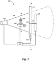
- Fig. 1 a partial view of an exemplary embodiment of a system in accordance with the disclosure is shown in Fig. 1 and is designated generally by reference character 100.
- Fig. 2 Other embodiments of systems in accordance with the disclosure, or aspects thereof, are provided in Fig. 2 , as will be described.
- the systems and methods described herein can be used to provide fast, reliable scans of objects in computed tomography with reduced scattering relative to traditional systems.
- the system 100 for computed tomography includes an illuminator 102 configured to form a cone of illumination 104.
- a rotational platform 106 within the cone of illumination 104 is configured to rotate an illuminated object 108 about a rotation axis A, as indicated by the curved arrow about axis A in Fig. 1 .
- a two-dimensional photodetector array 110 faces the illuminator 102 and is opposite the illuminator 102 from the rotational platform 106 for imaging the object 108 on the rotational platform 106 with illumination from the illuminator 102.
- the illuminator 102 is configured to emit x-ray radiation and the photodetector array 108 is sensitive to x-ray radiation, allowing for imaging of internal structures within the object 108 to construct a three-dimensional model of the object 108 that includes internal structure.
- a collimator shield 112 is positioned between the rotational platform 106 and the photodetector array 108.
- the collimator shield 112 defines a slit 114 therethrough for exposure of the photodetector array 108 to the cone of illumination 104 only through the slit 114 of the collimator shield 112.
- the portion 116 of the cone of illumination 104 that reaches the photodetector array 108 is shown schematically in Fig. 1 and those skilled in the art will readily appreciate that the collimator shield 112 is close enough to the photodetector array 108 to illuminate only a thin strip of the photodetector array 108 as low as a single pixel wide.
- the collimator shield 112 is operatively connected, e.g., by any suitable mechanical carriage, to the photodetector array 108 for movement relative to the photodetector array 108 in a direction along axis B perpendicular to the slit 114 for scanning the slit 114 along the photodetector array 108 to acquire a two dimensional image of the object 108 on the rotational platform 106.
- the rotation axis A is aligned parallel with the axis B, which lies in a direction perpendicular to the slit 114.
- the collimator shield 112 extends perpendicularly to the slit 114 in both directions, i.e., up and down as oriented in Fig. 1 , from the slit 114 to an extent that the collimator shield 112 shields the photodetector array 108 from the cone of illumination 104 entirely except for the portion 116 of the cone of illumination 104 passing through the slit 114, even with the slit 14 positioned at extreme ends of the photodetector array 108, i.e. even with the slit 114 at the top or bottom of the photodetector array 108 as oriented in Fig. 1 .
- the portion of the cone of illumination 104 that is blocked by the collimator shield is indicated schematically in Fig. 1 with broken lines.
- the collimator shield 112 includes a pair of spaced apart plates 118, i.e., spaced apart from one another along axis B, wherein the slit 114 is defined between the plates 118.
- Each plate can include a flat ground tungsten material or any other suitable material to provide precision for the shape and size of slit 114 as well as opacity to x-rays.
- the collimator shield 112 includes a respective lead shielding member 120 mounted to each plate 118. Any other suitable material for blocking the illumination can be used.
- the plates 118 are spaced apart from one another by a pair of shims 122, with one of the shims 122 at each end of the slit 114.
- a method of computed tomography includes illuminating an object, e.g., object 108, with a cone of illumination, e.g. cone of illumination 104, wherein the object is between a source, e.g., source 102, of the cone of illumination and a two-dimensional photo-detector array, e.g., photodetector array 108.
- the method includes shielding the photodetector array from cone of illumination with a collimator shield, e.g., collimator shield 112, that includes a slit defined therethrough and moving the slit of the collimator shield across the photodetector array in a direction perpendicular to the slit, as indicated with the double arrow in Fig. 1 , to expose the photodetector array to the cone of illumination through the slit as the slit scans across the photodetector array to acquire a two-dimensional image of the object.
- a collimator shield e.g., collimator shield 112 that includes a slit defined therethrough and moving the slit of the collimator shield across the photodetector array in a direction perpendicular to the slit, as indicated with the double arrow in Fig. 1 , to expose the photodetector array to the cone of illumination through the slit as the slit scans across the photodetector array to acquire
- the method includes rotating the object to a new rotational position, e.g., by rotating a fraction of a degree around rotational axis A, and then repeating movement of the slit along the length of the photodetector array to expose the photodetector to form another two-dimensional image of the object.
- the method includes rotating the object about the rotational axis again, scanning with the slit to image the object again, and repeatedly rotating and imaging so forth until the object has been scanned and imaged from multiple rotational positions to form a three-dimensional model of the object through reconstruction software.
- Software used for volumetric modeling with traditional DDA can be used for this purpose without necessitating the need for new software.
- systems and methods as disclosed herein do not require new acquisition algorithms to acquire images and produce volumetric models therefrom.
- a controller 124 can be connected to coordinate movement of the rotational platform 106 and linear movement of the collimating shield 112, e.g., by a linear actuator 126, to control the illuminator 102, and to collect and analyze imaging data from the photodetector array 108.
- Each repetition of movement of the slit can be in a reverse direction from the immediately previous movement of the slit, e.g., to save time by utilizing travel in both directions of the collimator shield.
- each repetition of movement of the slit 114 can be in the same direction by resetting the position of the slit before each image is obtained. Illuminating the object can be performed continuously as the slit moves across the photodetector array for each image, and illuminating the object can be performed continuously for multiple rotational positions of the object.
Landscapes
- Health & Medical Sciences (AREA)
- Chemical & Material Sciences (AREA)
- Biochemistry (AREA)
- Pulmonology (AREA)
- Radiology & Medical Imaging (AREA)
- Theoretical Computer Science (AREA)
- Physics & Mathematics (AREA)
- Nuclear Medicine, Radiotherapy & Molecular Imaging (AREA)
- Life Sciences & Earth Sciences (AREA)
- Analytical Chemistry (AREA)
- Engineering & Computer Science (AREA)
- General Health & Medical Sciences (AREA)
- General Physics & Mathematics (AREA)
- Immunology (AREA)
- Pathology (AREA)
- Apparatus For Radiation Diagnosis (AREA)
- Analysing Materials By The Use Of Radiation (AREA)
Abstract
Description
- The present disclosure relates to computed tomography, and more particularly to reducing scatter in industrial computed tomography, e.g., to improve three-dimensional inspection of precision manufactured parts.
- Industrial computed tomography (CT) scanning traditionally falls into two categories. Linear detector array (LDA) use a planar illumination source coupled with a linear detector array sensor. The sensor records an exposure of each rotational position as the part is repeatedly rotated and imaged. After a full rotation, the illumination source and sensor are moved to the next level on the part, and data for another full rotation is collected. This process is repeated until each level of a part has been scanned. The data can all be utilized to construct a volumetric model of the part. LDA systems reduce scatter by using the linear detector array but take a very long time to scan because if thousands of exposures are recorded at each level, and if there are thousands of levels, then millions of exposures must be recorded and reconciled into a model. The part must typically be rotated thousands of times to form a volumetric model of the part with LDA systems.
- Digital detector array (DDA or flat panel) systems use a cone shaped illumination source together with a two-dimensional array of detectors to record a single exposure of the whole part at each rotational position of the part until the part has been imaged for a full rotation of the part. The part only has to rotate once, so DDA systems are much faster at scanning than LDA systems, and the typical number of exposures is reduced by a factor of thousands. But DDA systems have issues with cross-scatter, resulting in scans that can be difficult to resolve or analyze.
- For a production CT inspection system, faster scan time is a priority, however x-ray scatter in DDA systems can result in data that is unusable. Traditional approaches to this problem have involved algorithmic compensation that helps resolve the DDA system data, however this also has limitations and ultimately the DDA system data may be unusable even with the algorithmic compensation.
- The conventional techniques have been considered satisfactory for their intended purpose. However, with an ongoing increase in the amount and complexity of additively manufactured parts with intricate internal geometries, there is an increasing need for fast, reliable computed tomography that overcomes the limitations of traditional techniques in producing useable data. This disclosure provides a solution for this need.
- A system for computed tomography includes an illuminator configured to form a cone of illumination. A rotational platform within the cone of illumination is configured to rotate an illuminated object about a rotation axis. A two-dimensional photodetector array faces the illuminator, opposite the illuminator from the rotational platform for imaging an object on the rotational platform with illumination from the illuminator. A collimator shield is positioned between the rotational platform and the photodetector array. The collimator shield defines a slit therethrough for exposure of the photodetector array to the cone of illumination only through the slit of the collimator shield. The collimator shield is operatively connected to the photodetector array for movement relative to the photodetector array in a direction perpendicular to the slit for scanning the slit along the photodetector array to acquire a two dimensional image of an object on the rotational platform.
- The rotation axis can be aligned with the direction perpendicular to the slit. The collimator shield can extend perpendicularly to the slit in both directions from the slit to an extent that shields the photodetector array from the cone of illumination entirely except for a portion of the cone of illumination passing through the slit even with the slit positioned at extreme ends of the photodetector array. The illuminator can be configured to emit x-ray radiation and the photodetector array can be sensitive to x-ray radiation. The collimator shield can include a pair of spaced apart plates wherein the slit is defined between the plates. The collimator shield can include a respective lead shielding member mounted to each plate. Each plate can include a material that is opaque to x-rays and is sufficiently rigid to maintain constant slot geometry such as flat ground tungsten material. The plates can be spaced apart from one another by a pair of shims, with one of the shims at each end of the slit.
- A method of computed tomography includes illuminating an object with a cone of illumination, wherein the object is between a source of the cone of illumination and a two-dimensional photo-detector array. The method includes shielding the photodetector array from the cone of illumination with a collimator shield that includes a slit defined therethrough and moving the slit of the collimator shield across the photodetector array in a direction perpendicular to the slit to expose the photodetector array to the cone of illumination through the slit as the slit scans across the photodetector array to acquire a two-dimensional image of the object. The method includes rotating the object about a rotational axis to a new rotational position and repeating movement of the slit to expose the photodetector and rotating the object along the axis until the object has been imaged from multiple rotational positions to form a three-dimensional model of the object.
- Each repetition of movement of the slit can be in a reverse direction from an immediately previous movement of the slit. It is also contemplated that each repetition of movement of the slit can be in the same direction. Illuminating the object can be performed continuously as the slit moves across the photodetector array. Illuminating the object can be performed continuously for multiple rotational positions of the object.
- These and other features of the systems and methods of the subject disclosure will become more readily apparent to those skilled in the art from the following detailed description of the preferred embodiments taken in conjunction with the drawings.
- So that those skilled in the art to which the subject disclosure appertains will readily understand how to make and use the devices and methods of the subject disclosure without undue experimentation, preferred embodiments thereof will be described in detail herein below with reference to certain figures, wherein:
-
Fig. 1 is a schematic perspective view of an exemplary embodiment of a system for computed tomography constructed in accordance with the present disclosure, showing the object being illuminated, the collimator shield, and the photodetector array; and -
Fig. 2 is a schematic side elevation view, not to any particular scale, of the collimator shield, showing the assembly of plates, shims, and shielding members. - Reference will now be made to the drawings wherein like reference numerals identify similar structural features or aspects of the subject disclosure. For purposes of explanation and illustration, and not limitation, a partial view of an exemplary embodiment of a system in accordance with the disclosure is shown in
Fig. 1 and is designated generally byreference character 100. Other embodiments of systems in accordance with the disclosure, or aspects thereof, are provided inFig. 2 , as will be described. The systems and methods described herein can be used to provide fast, reliable scans of objects in computed tomography with reduced scattering relative to traditional systems. - The
system 100 for computed tomography includes anilluminator 102 configured to form a cone ofillumination 104. Arotational platform 106 within the cone ofillumination 104 is configured to rotate anilluminated object 108 about a rotation axis A, as indicated by the curved arrow about axis A inFig. 1 . A two-dimensional photodetector array 110 faces theilluminator 102 and is opposite theilluminator 102 from therotational platform 106 for imaging theobject 108 on therotational platform 106 with illumination from theilluminator 102. Theilluminator 102 is configured to emit x-ray radiation and thephotodetector array 108 is sensitive to x-ray radiation, allowing for imaging of internal structures within theobject 108 to construct a three-dimensional model of theobject 108 that includes internal structure. - A
collimator shield 112 is positioned between therotational platform 106 and thephotodetector array 108. Thecollimator shield 112 defines aslit 114 therethrough for exposure of thephotodetector array 108 to the cone ofillumination 104 only through theslit 114 of thecollimator shield 112. Theportion 116 of the cone ofillumination 104 that reaches thephotodetector array 108 is shown schematically inFig. 1 and those skilled in the art will readily appreciate that thecollimator shield 112 is close enough to thephotodetector array 108 to illuminate only a thin strip of thephotodetector array 108 as low as a single pixel wide. Thecollimator shield 112 is operatively connected, e.g., by any suitable mechanical carriage, to thephotodetector array 108 for movement relative to thephotodetector array 108 in a direction along axis B perpendicular to theslit 114 for scanning theslit 114 along thephotodetector array 108 to acquire a two dimensional image of theobject 108 on therotational platform 106. The rotation axis A is aligned parallel with the axis B, which lies in a direction perpendicular to theslit 114. - The
collimator shield 112 extends perpendicularly to theslit 114 in both directions, i.e., up and down as oriented inFig. 1 , from theslit 114 to an extent that thecollimator shield 112 shields thephotodetector array 108 from the cone ofillumination 104 entirely except for theportion 116 of the cone ofillumination 104 passing through theslit 114, even with the slit 14 positioned at extreme ends of thephotodetector array 108, i.e. even with theslit 114 at the top or bottom of thephotodetector array 108 as oriented inFig. 1 . The portion of the cone ofillumination 104 that is blocked by the collimator shield is indicated schematically inFig. 1 with broken lines. - With reference now to
Fig. 2 , thecollimator shield 112 includes a pair of spaced apartplates 118, i.e., spaced apart from one another along axis B, wherein theslit 114 is defined between theplates 118. Each plate can include a flat ground tungsten material or any other suitable material to provide precision for the shape and size ofslit 114 as well as opacity to x-rays. Thecollimator shield 112 includes a respectivelead shielding member 120 mounted to eachplate 118. Any other suitable material for blocking the illumination can be used. Theplates 118 are spaced apart from one another by a pair ofshims 122, with one of theshims 122 at each end of theslit 114. - With reference again to
Fig. 1 , a method of computed tomography includes illuminating an object, e.g.,object 108, with a cone of illumination, e.g. cone ofillumination 104, wherein the object is between a source, e.g.,source 102, of the cone of illumination and a two-dimensional photo-detector array, e.g.,photodetector array 108. The method includes shielding the photodetector array from cone of illumination with a collimator shield, e.g.,collimator shield 112, that includes a slit defined therethrough and moving the slit of the collimator shield across the photodetector array in a direction perpendicular to the slit, as indicated with the double arrow inFig. 1 , to expose the photodetector array to the cone of illumination through the slit as the slit scans across the photodetector array to acquire a two-dimensional image of the object. - The method includes rotating the object to a new rotational position, e.g., by rotating a fraction of a degree around rotational axis A, and then repeating movement of the slit along the length of the photodetector array to expose the photodetector to form another two-dimensional image of the object. After the second image is obtained, the method includes rotating the object about the rotational axis again, scanning with the slit to image the object again, and repeatedly rotating and imaging so forth until the object has been scanned and imaged from multiple rotational positions to form a three-dimensional model of the object through reconstruction software. Software used for volumetric modeling with traditional DDA can be used for this purpose without necessitating the need for new software. Similarly, systems and methods as disclosed herein do not require new acquisition algorithms to acquire images and produce volumetric models therefrom.
- A
controller 124 can be connected to coordinate movement of therotational platform 106 and linear movement of thecollimating shield 112, e.g., by alinear actuator 126, to control theilluminator 102, and to collect and analyze imaging data from thephotodetector array 108. Each repetition of movement of the slit can be in a reverse direction from the immediately previous movement of the slit, e.g., to save time by utilizing travel in both directions of the collimator shield. However, those skilled in the art will readily appreciate that each repetition of movement of theslit 114 can be in the same direction by resetting the position of the slit before each image is obtained. Illuminating the object can be performed continuously as the slit moves across the photodetector array for each image, and illuminating the object can be performed continuously for multiple rotational positions of the object. - The methods and systems of the present disclosure, as described above and shown in the drawings, provide for computed tomography with superior properties including reduced scattering relative to traditional digital detector array (DDA) systems with scan speed greater than that of traditional linear detector array (LDA) systems. While the apparatus and methods of the subject disclosure have been shown and described with reference to preferred embodiments, those skilled in the art will readily appreciate that changes and/or modifications may be made thereto without departing from the scope of the invention as defined by the claims.
Claims (15)
- A method of computed tomography comprising:illuminating an object (108) with a cone of illumination (104), wherein the object is between a source (102) of the cone of illumination (104) and a two-dimensional photo-detector array (110);shielding the photodetector array (110) from the cone of illumination (104) with a collimator shield (112) that includes a slit (114) defined therethrough;moving the slit (114) of the collimator shield (112) across the photodetector array (110) in a direction perpendicular to the slit (114) to expose the photodetector array (110) to the cone of illumination (104) through the slit (114) as the slit (114) scans across the photodetector array (110) to acquire a two-dimensional image of the object (108);rotating the object (108) about a rotational axis to a new rotational position; andrepeating movement of the slit (114) to expose the photodetector (110) and rotating the object (108) about the rotational axis until the object (108) has been imaged from multiple rotational positions to form a three-dimensional model of the object (108).
- The method as recited in claim 1, wherein rotating the object (108) includes rotating the object (108) wherein the rotational axis aligned with the direction perpendicular to the slit (114).
- The method as recited in claim 1 or 2, wherein each repetition of movement of the slit (114) is in a reverse direction from an immediately previous movement of the slit (114), or wherein each repetition of movement of the slit (114) is in the same direction.
- The method as recited in any preceding claim, wherein illuminating the object (108) is performed continuously as the slit (114) moves across the photodetector array (110).
- The method as recited in claim 4, wherein illuminating the object (108) is performed continuously for multiple rotational positions of the object (108).
- The method as recited in any preceding claim, wherein the collimator shield (112) extends perpendicularly to the slit (114) in both directions from the slit (114) to an extent that shields the photodetector array (110) from the cone of illumination (104) entirely except for a portion of the cone of illumination (104) passing through the slit (114) even with the slit (114) positioned at extreme ends of the photodetector array (110).
- The method as recited in ant preceding claim, wherein illuminating the object (108) includes illuminating the object (108) with x-ray radiation, wherein the photodetector array (110) is sensitive to x-ray radiation.
- A system for computed tomography comprising:an illuminator (102) configured to form a cone of illumination (104);a rotational platform (106) within the cone of illumination (104) configured to rotate an illuminated object (108) about a rotation axis;a two-dimensional photodetector array (110) facing the illuminator (102), opposite the illuminator (102) from the rotational platform (106) for imaging an object (108) on the rotational platform (106) with illumination from the illuminator (102); anda collimator shield (112) between the rotational platform (106) and the photodetector array (110), the collimator shield (112) defining a slit (114) therethrough for exposure of the photodetector array (110) to the cone of illumination (104) only through the slit (114) of the collimator shield (112), wherein the collimator shield is operatively connected to the photodetector array (110) for movement relative to the photodetector array (110) in a direction perpendicular to the slit (114) for scanning the slit (114) along the photodetector array (110) to acquire a two dimensional image of an object (108) on the rotational platform (106).
- The system as recited in claim 8, wherein the rotation axis is aligned with the direction perpendicular to the slit (114).
- The system as recited in claim 8 or 9, wherein the collimator shield (112) extends perpendicularly to the slit (114) in both directions from the slit (114) to an extent that shields the photodetector array (110) from the cone of illumination (104) entirely except for a portion of the cone of illumination (104) passing through the slit (114) even with the slit positioned at extreme ends of the photodetector array (110).
- The system as recited in claim 8, 9 or 10, wherein illuminator (102) is configured to emit x-ray radiation and wherein the photodetector array (110) is sensitive to x-ray radiation.
- The system as recited in any of claims 8 to 11, wherein the collimator shield (112) includes a pair of spaced apart plates (118) wherein the slit (114) is defined between the plates (118), and preferably wherein the collimator shield (112) includes a respective lead shielding member (120) mounted to each plate (118).
- The system as recited in claim 12, wherein each plate (118) includes a material that is opaque to x-rays and is sufficiently rigid to maintain constant slot geometry.
- The system as recited in claim 13, wherein each plate (118) includes a flat ground tungsten material.
- The system as recited in claim 12, 13 or 14 wherein the plates (118) are spaced apart from one another by a pair of shims (122), with one of the shims at each end of the slit (114).
Applications Claiming Priority (1)
| Application Number | Priority Date | Filing Date | Title |
|---|---|---|---|
| US15/989,636 US10948428B2 (en) | 2018-05-25 | 2018-05-25 | Reducing scatter for computed tomography |
Publications (2)
| Publication Number | Publication Date |
|---|---|
| EP3588066A1 true EP3588066A1 (en) | 2020-01-01 |
| EP3588066B1 EP3588066B1 (en) | 2022-06-29 |
Family
ID=66668722
Family Applications (1)
| Application Number | Title | Priority Date | Filing Date |
|---|---|---|---|
| EP19176538.7A Active EP3588066B1 (en) | 2018-05-25 | 2019-05-24 | Method and system for reducing scatter for computed tomography |
Country Status (2)
| Country | Link |
|---|---|
| US (1) | US10948428B2 (en) |
| EP (1) | EP3588066B1 (en) |
Families Citing this family (1)
| Publication number | Priority date | Publication date | Assignee | Title |
|---|---|---|---|---|
| CN112964738B (en) * | 2021-01-29 | 2022-11-22 | 山东大学 | Industrial CT rapid scanning system and method |
Citations (3)
| Publication number | Priority date | Publication date | Assignee | Title |
|---|---|---|---|---|
| US6339636B1 (en) * | 1999-03-19 | 2002-01-15 | Fuji Photo Film Co., Ltd. | Radiation image recording method and apparatus |
| US20030223547A1 (en) * | 2002-05-31 | 2003-12-04 | General Electric Company | X-ray inspection apparatus and method |
| US20150297158A1 (en) * | 2012-09-07 | 2015-10-22 | Trophy | Apparatus for partial ct imaging |
Family Cites Families (13)
| Publication number | Priority date | Publication date | Assignee | Title |
|---|---|---|---|---|
| US4203037A (en) | 1977-08-01 | 1980-05-13 | University Of Pittsburgh | Collimated radiation apparatus |
| US6175609B1 (en) | 1999-04-20 | 2001-01-16 | General Electric Company | Methods and apparatus for scanning an object in a computed tomography system |
| SE523589C2 (en) * | 2002-02-15 | 2004-05-04 | Xcounter Ab | Apparatus and method for detecting radiation using scanning |
| US7242749B2 (en) * | 2005-11-15 | 2007-07-10 | General Electric Company | Methods and systems for dynamic pitch helical scanning |
| WO2011066275A2 (en) * | 2009-11-25 | 2011-06-03 | Massachusetts Institute Of Technology | Actively addressable aperture light field camera |
| US9347893B2 (en) | 2011-07-26 | 2016-05-24 | Robert Sigurd Nelson | Enhanced resolution imaging systems for digital radiography |
| US8989348B2 (en) * | 2011-11-18 | 2015-03-24 | Visuum, Llc | Multi-linear X-ray scanning systems and methods for X-ray scanning |
| WO2015019232A2 (en) * | 2013-08-08 | 2015-02-12 | Controlrad Systems Inc. | X-ray reduction system |
| EP3146526B1 (en) | 2014-05-19 | 2018-12-26 | 3Shape A/S | A radiographic system and method for reducing motion blur and scatter radiation |
| US9204848B2 (en) * | 2015-01-26 | 2015-12-08 | Martin Annis Patent Trust—2009 | Low-dose X-ray backscatter system for three dimensional medical imaging using a conventional X-ray tube |
| WO2017001294A1 (en) * | 2015-06-30 | 2017-01-05 | Koninklijke Philips N.V. | Scanning x-ray apparatus with full-field detector |
| KR20170093500A (en) * | 2016-02-05 | 2017-08-16 | 주식회사바텍 | X-ray collimator and x-ray imaging apparatus using the same |
| US20200041427A1 (en) * | 2017-11-16 | 2020-02-06 | XRD by Design LLC | Compact, Low Cost Apparatus for Testing of Production and Counterfeit Pharmaceuticals and Other Crystalline Materials |
-
2018
- 2018-05-25 US US15/989,636 patent/US10948428B2/en active Active
-
2019
- 2019-05-24 EP EP19176538.7A patent/EP3588066B1/en active Active
Patent Citations (3)
| Publication number | Priority date | Publication date | Assignee | Title |
|---|---|---|---|---|
| US6339636B1 (en) * | 1999-03-19 | 2002-01-15 | Fuji Photo Film Co., Ltd. | Radiation image recording method and apparatus |
| US20030223547A1 (en) * | 2002-05-31 | 2003-12-04 | General Electric Company | X-ray inspection apparatus and method |
| US20150297158A1 (en) * | 2012-09-07 | 2015-10-22 | Trophy | Apparatus for partial ct imaging |
Non-Patent Citations (1)
| Title |
|---|
| W W SUN ET AL: "An overview of industrial X-ray computed tomography", 31 January 2012 (2012-01-31), pages 1 - 55, XP055644164, Retrieved from the Internet <URL:http://eprintspublications.npl.co.uk/5385/1/ENG32.pdf> [retrieved on 20191119] * |
Also Published As
| Publication number | Publication date |
|---|---|
| EP3588066B1 (en) | 2022-06-29 |
| US20190360947A1 (en) | 2019-11-28 |
| US10948428B2 (en) | 2021-03-16 |
Similar Documents
| Publication | Publication Date | Title |
|---|---|---|
| US10481110B2 (en) | Radiographic image generating device | |
| KR101632046B1 (en) | High-resolution computed tomography | |
| RU2334973C1 (en) | System and method for image reengineering by means of scanning by rectilinear trajectory | |
| CN102028490B (en) | Method and apparatus for determining an image from X-ray projections recorded when traversing a trajectory | |
| EP2981813B1 (en) | Helical computed tomography | |
| US9453804B2 (en) | Method and apparatus for generating a representation of an internal structure of an object | |
| CN110891489B (en) | Reference detector element combined with anti-scatter collimator | |
| CN106999125A (en) | Source detector arrangement | |
| KR20010081097A (en) | Computerized tomography for non-destructive testing | |
| EP3850346B1 (en) | Dynamic radiation collimation for non-destructive analysis of test objects | |
| WO2009124774A1 (en) | Apparatus and method for non-rotational computed tomography | |
| US20210244373A1 (en) | X-ray phase constrast detector | |
| US11272894B2 (en) | X-ray imaging device | |
| JP2016087466A (en) | X-ray ct apparatus and method for controlling the same | |
| EP3588066B1 (en) | Method and system for reducing scatter for computed tomography | |
| US20210172885A1 (en) | X-ray imaging device | |
| US12248108B2 (en) | High-resolution detector having a reduced number of pixels | |
| KR102426991B1 (en) | radiographic imaging device | |
| JP2014223091A (en) | Radiographic apparatus and image processing method | |
| JP4062232B2 (en) | X-ray CT apparatus and imaging method using X-ray CT apparatus | |
| US9633423B2 (en) | Method of reduction of septal shadows for thick septa collimators | |
| PL240067B1 (en) | Method and system for object imaging using backscattered X-ray photons |
Legal Events
| Date | Code | Title | Description |
|---|---|---|---|
| PUAI | Public reference made under article 153(3) epc to a published international application that has entered the european phase |
Free format text: ORIGINAL CODE: 0009012 |
|
| STAA | Information on the status of an ep patent application or granted ep patent |
Free format text: STATUS: THE APPLICATION HAS BEEN PUBLISHED |
|
| AK | Designated contracting states |
Kind code of ref document: A1 Designated state(s): AL AT BE BG CH CY CZ DE DK EE ES FI FR GB GR HR HU IE IS IT LI LT LU LV MC MK MT NL NO PL PT RO RS SE SI SK SM TR |
|
| AX | Request for extension of the european patent |
Extension state: BA ME |
|
| STAA | Information on the status of an ep patent application or granted ep patent |
Free format text: STATUS: REQUEST FOR EXAMINATION WAS MADE |
|
| 17P | Request for examination filed |
Effective date: 20200701 |
|
| RBV | Designated contracting states (corrected) |
Designated state(s): AL AT BE BG CH CY CZ DE DK EE ES FI FR GB GR HR HU IE IS IT LI LT LU LV MC MK MT NL NO PL PT RO RS SE SI SK SM TR |
|
| GRAP | Despatch of communication of intention to grant a patent |
Free format text: ORIGINAL CODE: EPIDOSNIGR1 |
|
| STAA | Information on the status of an ep patent application or granted ep patent |
Free format text: STATUS: GRANT OF PATENT IS INTENDED |
|
| INTG | Intention to grant announced |
Effective date: 20211129 |
|
| GRAS | Grant fee paid |
Free format text: ORIGINAL CODE: EPIDOSNIGR3 |
|
| RAP3 | Party data changed (applicant data changed or rights of an application transferred) |
Owner name: COLLINS ENGINE NOZZLES, INC. |
|
| GRAA | (expected) grant |
Free format text: ORIGINAL CODE: 0009210 |
|
| STAA | Information on the status of an ep patent application or granted ep patent |
Free format text: STATUS: THE PATENT HAS BEEN GRANTED |
|
| AK | Designated contracting states |
Kind code of ref document: B1 Designated state(s): AL AT BE BG CH CY CZ DE DK EE ES FI FR GB GR HR HU IE IS IT LI LT LU LV MC MK MT NL NO PL PT RO RS SE SI SK SM TR |
|
| REG | Reference to a national code |
Ref country code: CH Ref legal event code: EP |
|
| REG | Reference to a national code |
Ref country code: AT Ref legal event code: REF Ref document number: 1501660 Country of ref document: AT Kind code of ref document: T Effective date: 20220715 |
|
| REG | Reference to a national code |
Ref country code: IE Ref legal event code: FG4D |
|
| REG | Reference to a national code |
Ref country code: DE Ref legal event code: R096 Ref document number: 602019016339 Country of ref document: DE |
|
| REG | Reference to a national code |
Ref country code: LT Ref legal event code: MG9D |
|
| PG25 | Lapsed in a contracting state [announced via postgrant information from national office to epo] |
Ref country code: SE Free format text: LAPSE BECAUSE OF FAILURE TO SUBMIT A TRANSLATION OF THE DESCRIPTION OR TO PAY THE FEE WITHIN THE PRESCRIBED TIME-LIMIT Effective date: 20220629 Ref country code: NO Free format text: LAPSE BECAUSE OF FAILURE TO SUBMIT A TRANSLATION OF THE DESCRIPTION OR TO PAY THE FEE WITHIN THE PRESCRIBED TIME-LIMIT Effective date: 20220929 Ref country code: LT Free format text: LAPSE BECAUSE OF FAILURE TO SUBMIT A TRANSLATION OF THE DESCRIPTION OR TO PAY THE FEE WITHIN THE PRESCRIBED TIME-LIMIT Effective date: 20220629 Ref country code: HR Free format text: LAPSE BECAUSE OF FAILURE TO SUBMIT A TRANSLATION OF THE DESCRIPTION OR TO PAY THE FEE WITHIN THE PRESCRIBED TIME-LIMIT Effective date: 20220629 Ref country code: GR Free format text: LAPSE BECAUSE OF FAILURE TO SUBMIT A TRANSLATION OF THE DESCRIPTION OR TO PAY THE FEE WITHIN THE PRESCRIBED TIME-LIMIT Effective date: 20220930 Ref country code: FI Free format text: LAPSE BECAUSE OF FAILURE TO SUBMIT A TRANSLATION OF THE DESCRIPTION OR TO PAY THE FEE WITHIN THE PRESCRIBED TIME-LIMIT Effective date: 20220629 Ref country code: BG Free format text: LAPSE BECAUSE OF FAILURE TO SUBMIT A TRANSLATION OF THE DESCRIPTION OR TO PAY THE FEE WITHIN THE PRESCRIBED TIME-LIMIT Effective date: 20220929 |
|
| REG | Reference to a national code |
Ref country code: NL Ref legal event code: MP Effective date: 20220629 |
|
| REG | Reference to a national code |
Ref country code: AT Ref legal event code: MK05 Ref document number: 1501660 Country of ref document: AT Kind code of ref document: T Effective date: 20220629 |
|
| PG25 | Lapsed in a contracting state [announced via postgrant information from national office to epo] |
Ref country code: RS Free format text: LAPSE BECAUSE OF FAILURE TO SUBMIT A TRANSLATION OF THE DESCRIPTION OR TO PAY THE FEE WITHIN THE PRESCRIBED TIME-LIMIT Effective date: 20220629 Ref country code: LV Free format text: LAPSE BECAUSE OF FAILURE TO SUBMIT A TRANSLATION OF THE DESCRIPTION OR TO PAY THE FEE WITHIN THE PRESCRIBED TIME-LIMIT Effective date: 20220629 |
|
| PG25 | Lapsed in a contracting state [announced via postgrant information from national office to epo] |
Ref country code: NL Free format text: LAPSE BECAUSE OF FAILURE TO SUBMIT A TRANSLATION OF THE DESCRIPTION OR TO PAY THE FEE WITHIN THE PRESCRIBED TIME-LIMIT Effective date: 20220629 |
|
| PG25 | Lapsed in a contracting state [announced via postgrant information from national office to epo] |
Ref country code: SM Free format text: LAPSE BECAUSE OF FAILURE TO SUBMIT A TRANSLATION OF THE DESCRIPTION OR TO PAY THE FEE WITHIN THE PRESCRIBED TIME-LIMIT Effective date: 20220629 Ref country code: SK Free format text: LAPSE BECAUSE OF FAILURE TO SUBMIT A TRANSLATION OF THE DESCRIPTION OR TO PAY THE FEE WITHIN THE PRESCRIBED TIME-LIMIT Effective date: 20220629 Ref country code: RO Free format text: LAPSE BECAUSE OF FAILURE TO SUBMIT A TRANSLATION OF THE DESCRIPTION OR TO PAY THE FEE WITHIN THE PRESCRIBED TIME-LIMIT Effective date: 20220629 Ref country code: PT Free format text: LAPSE BECAUSE OF FAILURE TO SUBMIT A TRANSLATION OF THE DESCRIPTION OR TO PAY THE FEE WITHIN THE PRESCRIBED TIME-LIMIT Effective date: 20221031 Ref country code: ES Free format text: LAPSE BECAUSE OF FAILURE TO SUBMIT A TRANSLATION OF THE DESCRIPTION OR TO PAY THE FEE WITHIN THE PRESCRIBED TIME-LIMIT Effective date: 20220629 Ref country code: EE Free format text: LAPSE BECAUSE OF FAILURE TO SUBMIT A TRANSLATION OF THE DESCRIPTION OR TO PAY THE FEE WITHIN THE PRESCRIBED TIME-LIMIT Effective date: 20220629 Ref country code: AT Free format text: LAPSE BECAUSE OF FAILURE TO SUBMIT A TRANSLATION OF THE DESCRIPTION OR TO PAY THE FEE WITHIN THE PRESCRIBED TIME-LIMIT Effective date: 20220629 |
|
| PG25 | Lapsed in a contracting state [announced via postgrant information from national office to epo] |
Ref country code: PL Free format text: LAPSE BECAUSE OF FAILURE TO SUBMIT A TRANSLATION OF THE DESCRIPTION OR TO PAY THE FEE WITHIN THE PRESCRIBED TIME-LIMIT Effective date: 20220629 Ref country code: IS Free format text: LAPSE BECAUSE OF FAILURE TO SUBMIT A TRANSLATION OF THE DESCRIPTION OR TO PAY THE FEE WITHIN THE PRESCRIBED TIME-LIMIT Effective date: 20221029 |
|
| REG | Reference to a national code |
Ref country code: DE Ref legal event code: R097 Ref document number: 602019016339 Country of ref document: DE |
|
| PG25 | Lapsed in a contracting state [announced via postgrant information from national office to epo] |
Ref country code: AL Free format text: LAPSE BECAUSE OF FAILURE TO SUBMIT A TRANSLATION OF THE DESCRIPTION OR TO PAY THE FEE WITHIN THE PRESCRIBED TIME-LIMIT Effective date: 20220629 |
|
| PG25 | Lapsed in a contracting state [announced via postgrant information from national office to epo] |
Ref country code: DK Free format text: LAPSE BECAUSE OF FAILURE TO SUBMIT A TRANSLATION OF THE DESCRIPTION OR TO PAY THE FEE WITHIN THE PRESCRIBED TIME-LIMIT Effective date: 20220629 Ref country code: CZ Free format text: LAPSE BECAUSE OF FAILURE TO SUBMIT A TRANSLATION OF THE DESCRIPTION OR TO PAY THE FEE WITHIN THE PRESCRIBED TIME-LIMIT Effective date: 20220629 |
|
| PLBE | No opposition filed within time limit |
Free format text: ORIGINAL CODE: 0009261 |
|
| STAA | Information on the status of an ep patent application or granted ep patent |
Free format text: STATUS: NO OPPOSITION FILED WITHIN TIME LIMIT |
|
| 26N | No opposition filed |
Effective date: 20230330 |
|
| P01 | Opt-out of the competence of the unified patent court (upc) registered |
Effective date: 20230530 |
|
| PG25 | Lapsed in a contracting state [announced via postgrant information from national office to epo] |
Ref country code: SI Free format text: LAPSE BECAUSE OF FAILURE TO SUBMIT A TRANSLATION OF THE DESCRIPTION OR TO PAY THE FEE WITHIN THE PRESCRIBED TIME-LIMIT Effective date: 20220629 |
|
| REG | Reference to a national code |
Ref country code: CH Ref legal event code: PL |
|
| PG25 | Lapsed in a contracting state [announced via postgrant information from national office to epo] |
Ref country code: MC Free format text: LAPSE BECAUSE OF FAILURE TO SUBMIT A TRANSLATION OF THE DESCRIPTION OR TO PAY THE FEE WITHIN THE PRESCRIBED TIME-LIMIT Effective date: 20220629 |
|
| REG | Reference to a national code |
Ref country code: BE Ref legal event code: MM Effective date: 20230531 |
|
| PG25 | Lapsed in a contracting state [announced via postgrant information from national office to epo] |
Ref country code: MC Free format text: LAPSE BECAUSE OF FAILURE TO SUBMIT A TRANSLATION OF THE DESCRIPTION OR TO PAY THE FEE WITHIN THE PRESCRIBED TIME-LIMIT Effective date: 20220629 Ref country code: LU Free format text: LAPSE BECAUSE OF NON-PAYMENT OF DUE FEES Effective date: 20230524 Ref country code: LI Free format text: LAPSE BECAUSE OF NON-PAYMENT OF DUE FEES Effective date: 20230531 Ref country code: IT Free format text: LAPSE BECAUSE OF FAILURE TO SUBMIT A TRANSLATION OF THE DESCRIPTION OR TO PAY THE FEE WITHIN THE PRESCRIBED TIME-LIMIT Effective date: 20220629 Ref country code: CH Free format text: LAPSE BECAUSE OF NON-PAYMENT OF DUE FEES Effective date: 20230531 |
|
| REG | Reference to a national code |
Ref country code: IE Ref legal event code: MM4A |
|
| PG25 | Lapsed in a contracting state [announced via postgrant information from national office to epo] |
Ref country code: IE Free format text: LAPSE BECAUSE OF NON-PAYMENT OF DUE FEES Effective date: 20230524 |
|
| PG25 | Lapsed in a contracting state [announced via postgrant information from national office to epo] |
Ref country code: IE Free format text: LAPSE BECAUSE OF NON-PAYMENT OF DUE FEES Effective date: 20230524 |
|
| PG25 | Lapsed in a contracting state [announced via postgrant information from national office to epo] |
Ref country code: BE Free format text: LAPSE BECAUSE OF NON-PAYMENT OF DUE FEES Effective date: 20230531 |
|
| PG25 | Lapsed in a contracting state [announced via postgrant information from national office to epo] |
Ref country code: BG Free format text: LAPSE BECAUSE OF FAILURE TO SUBMIT A TRANSLATION OF THE DESCRIPTION OR TO PAY THE FEE WITHIN THE PRESCRIBED TIME-LIMIT Effective date: 20220629 |
|
| PG25 | Lapsed in a contracting state [announced via postgrant information from national office to epo] |
Ref country code: BG Free format text: LAPSE BECAUSE OF FAILURE TO SUBMIT A TRANSLATION OF THE DESCRIPTION OR TO PAY THE FEE WITHIN THE PRESCRIBED TIME-LIMIT Effective date: 20220629 |
|
| PG25 | Lapsed in a contracting state [announced via postgrant information from national office to epo] |
Ref country code: CY Free format text: LAPSE BECAUSE OF FAILURE TO SUBMIT A TRANSLATION OF THE DESCRIPTION OR TO PAY THE FEE WITHIN THE PRESCRIBED TIME-LIMIT; INVALID AB INITIO Effective date: 20190524 |
|
| PG25 | Lapsed in a contracting state [announced via postgrant information from national office to epo] |
Ref country code: HU Free format text: LAPSE BECAUSE OF FAILURE TO SUBMIT A TRANSLATION OF THE DESCRIPTION OR TO PAY THE FEE WITHIN THE PRESCRIBED TIME-LIMIT; INVALID AB INITIO Effective date: 20190524 |
|
| PG25 | Lapsed in a contracting state [announced via postgrant information from national office to epo] |
Ref country code: TR Free format text: LAPSE BECAUSE OF FAILURE TO SUBMIT A TRANSLATION OF THE DESCRIPTION OR TO PAY THE FEE WITHIN THE PRESCRIBED TIME-LIMIT Effective date: 20220629 |
|
| PGFP | Annual fee paid to national office [announced via postgrant information from national office to epo] |
Ref country code: GB Payment date: 20260421 Year of fee payment: 8 |
|
| PGFP | Annual fee paid to national office [announced via postgrant information from national office to epo] |
Ref country code: DE Payment date: 20260421 Year of fee payment: 8 |
|
| PGFP | Annual fee paid to national office [announced via postgrant information from national office to epo] |
Ref country code: FR Payment date: 20260422 Year of fee payment: 8 |