EP3588000A1 - Shaft centerline alignment system for rotating equipment - Google Patents
Shaft centerline alignment system for rotating equipment Download PDFInfo
- Publication number
- EP3588000A1 EP3588000A1 EP19181835.0A EP19181835A EP3588000A1 EP 3588000 A1 EP3588000 A1 EP 3588000A1 EP 19181835 A EP19181835 A EP 19181835A EP 3588000 A1 EP3588000 A1 EP 3588000A1
- Authority
- EP
- European Patent Office
- Prior art keywords
- laser
- roller stand
- front plate
- back plate
- laser beam
- Prior art date
- Legal status (The legal status is an assumption and is not a legal conclusion. Google has not performed a legal analysis and makes no representation as to the accuracy of the status listed.)
- Granted
Links
Images









Classifications
-
- G—PHYSICS
- G01—MEASURING; TESTING
- G01B—MEASURING LENGTH, THICKNESS OR SIMILAR LINEAR DIMENSIONS; MEASURING ANGLES; MEASURING AREAS; MEASURING IRREGULARITIES OF SURFACES OR CONTOURS
- G01B11/00—Measuring arrangements characterised by the use of optical techniques
- G01B11/26—Measuring arrangements characterised by the use of optical techniques for measuring angles or tapers; for testing the alignment of axes
- G01B11/27—Measuring arrangements characterised by the use of optical techniques for measuring angles or tapers; for testing the alignment of axes for testing the alignment of axes
- G01B11/272—Measuring arrangements characterised by the use of optical techniques for measuring angles or tapers; for testing the alignment of axes for testing the alignment of axes using photoelectric detection means
-
- F—MECHANICAL ENGINEERING; LIGHTING; HEATING; WEAPONS; BLASTING
- F01—MACHINES OR ENGINES IN GENERAL; ENGINE PLANTS IN GENERAL; STEAM ENGINES
- F01D—NON-POSITIVE DISPLACEMENT MACHINES OR ENGINES, e.g. STEAM TURBINES
- F01D21/00—Shutting-down of machines or engines, e.g. in emergency; Regulating, controlling, or safety means not otherwise provided for
- F01D21/003—Arrangements for testing or measuring
-
- F—MECHANICAL ENGINEERING; LIGHTING; HEATING; WEAPONS; BLASTING
- F01—MACHINES OR ENGINES IN GENERAL; ENGINE PLANTS IN GENERAL; STEAM ENGINES
- F01D—NON-POSITIVE DISPLACEMENT MACHINES OR ENGINES, e.g. STEAM TURBINES
- F01D25/00—Component parts, details, or accessories, not provided for in, or of interest apart from, other groups
- F01D25/28—Supporting or mounting arrangements, e.g. for turbine casing
- F01D25/285—Temporary support structures, e.g. for testing, assembling, installing, repairing; Assembly methods using such structures
-
- F—MECHANICAL ENGINEERING; LIGHTING; HEATING; WEAPONS; BLASTING
- F01—MACHINES OR ENGINES IN GENERAL; ENGINE PLANTS IN GENERAL; STEAM ENGINES
- F01D—NON-POSITIVE DISPLACEMENT MACHINES OR ENGINES, e.g. STEAM TURBINES
- F01D5/00—Blades; Blade-carrying members; Heating, heat-insulating, cooling or antivibration means on the blades or the members
- F01D5/02—Blade-carrying members, e.g. rotors
- F01D5/027—Arrangements for balancing
-
- G—PHYSICS
- G01—MEASURING; TESTING
- G01B—MEASURING LENGTH, THICKNESS OR SIMILAR LINEAR DIMENSIONS; MEASURING ANGLES; MEASURING AREAS; MEASURING IRREGULARITIES OF SURFACES OR CONTOURS
- G01B11/00—Measuring arrangements characterised by the use of optical techniques
- G01B11/08—Measuring arrangements characterised by the use of optical techniques for measuring diameters
- G01B11/10—Measuring arrangements characterised by the use of optical techniques for measuring diameters of objects while moving
-
- G—PHYSICS
- G01—MEASURING; TESTING
- G01B—MEASURING LENGTH, THICKNESS OR SIMILAR LINEAR DIMENSIONS; MEASURING ANGLES; MEASURING AREAS; MEASURING IRREGULARITIES OF SURFACES OR CONTOURS
- G01B11/00—Measuring arrangements characterised by the use of optical techniques
- G01B11/26—Measuring arrangements characterised by the use of optical techniques for measuring angles or tapers; for testing the alignment of axes
- G01B11/27—Measuring arrangements characterised by the use of optical techniques for measuring angles or tapers; for testing the alignment of axes for testing the alignment of axes
-
- F—MECHANICAL ENGINEERING; LIGHTING; HEATING; WEAPONS; BLASTING
- F05—INDEXING SCHEMES RELATING TO ENGINES OR PUMPS IN VARIOUS SUBCLASSES OF CLASSES F01-F04
- F05D—INDEXING SCHEME FOR ASPECTS RELATING TO NON-POSITIVE-DISPLACEMENT MACHINES OR ENGINES, GAS-TURBINES OR JET-PROPULSION PLANTS
- F05D2230/00—Manufacture
- F05D2230/60—Assembly methods
- F05D2230/64—Assembly methods using positioning or alignment devices for aligning or centring, e.g. pins
Definitions
- the present disclosure relates generally to the field of alignment equipment and, more specifically, to a system and method that use a laser beam to align the shaft centerline of rotating equipment, such as a gas turbine rotor.
- the rotor is supported by oppositely disposed roller stands, and the position of at least one of the roller stands may be adjusted such that a laser beam originating from one roller stand contacts the center of a target on an opposing roller stand.
- the adjustment of the roller stand is performed automatically using hydraulic cylinders coupled to a control unit that receives data about the position of the laser beam relative to the target.
- gas turbine systems include a compressor, one or more combustors, and a turbine. Air may be drawn into a compressor, via its inlet, where the air is compressed by passing through multiple stages of rotating blades and stationary nozzles. The compressed air is directed to the one or more combustors, where fuel is introduced, and a fuel/air mixture is ignited and burned to form combustion products. The combustion products function as the operational fluid of the turbine.
- the operational fluid then flows through a fluid flow path in a turbine, the flow path being defined between a plurality of rotating blades and a plurality of stationary nozzles disposed between the rotating blades, such that each set of rotating blades and each corresponding set of stationary nozzles defines a turbine stage.
- a generator coupled to the rotor, may generate power from the rotation of the rotor.
- the rotation of the turbine blades also causes rotation of the compressor blades, which are coupled to the rotor.
- a gas turbine rotor may be removed from the gas turbine casing and supported on each end by a roller system to permit inspection and servicing of the rotor, the compressor blades, and/or the turbine blades.
- the roller system may include a powered roller stand and an idler roller stand. It is necessary to position the rotor stands to achieve perfect alignment of the rotor centerline within the roller stands to prevent the rotor from moving axially ("walking") off the roller stands, as the rotor is rotated at slow speeds. With perfect alignment, the rotor journal bearing surfaces are level and aligned with each other. If the rotor is not perfectly aligned within the roller stands, the technicians are required to stop their inspection or maintenance processes and re-align the roller stands, which is a time-consuming process.
- the alignment process has required the skills of two technicians, using rudimentary tools such as tape measures, to measure the alignment of the roller stands and to adjust the roller stands, using shims, until the desired perfect alignment is achieved. In some instances, this process could occupy the time of the two technicians for as long as eight hours.
- the system includes a laser transmission unit on the first stand and a target unit on the second stand.
- the laser transmission unit includes a laser that transmits a laser beam to a target on the target unit. When the laser beam contacts the center of the target, the roller stands are aligned.
- the system may be automated to detect the position of the laser beam relative to the target center and to adjust, as needed, the position of one of or both the roller stands using hydraulic cylinders coupled to a roller stand platform. The system and method reduce the time, effort, and manpower required to perform the alignment.
- an alignment system for aligning the shaft centerline of rotating equipment positioned on opposing roller stands.
- the alignment system includes a laser transmission unit configured for engagement with a first roller stand and a target unit configured for engagement with a second roller stand axially spaced from the first roller stand.
- the laser transmission unit includes a first front plate defining a first laser transmission hole therethrough, a first back plate axially spaced from the first front plate, a first arcuate panel extending axially between the first front plate and the first back plate and being configured to contact a first pair of roller wheels of the first roller stand, and a laser centrally mounted through the first back plate and extending to the first front plate, such that a laser beam produced by the laser is transmitted through the first laser transmission hole of the first front plate.
- the target unit includes a second front plate defining a second laser transmission hole therethrough, a second back plate axially spaced from the second front plate and being provided with an image of a target, the target having a center aligned with the second laser transmission hole, and a second arcuate panel extending axially between the second front plate and the second back plate and being configured to contact a second pair of roller wheels of the second roller stand.
- a method of aligning the heights of opposing roller stands includes: positioning a laser transmission unit on a first roller stand and a target unit on a second roller stand; directing a laser beam from the laser transmission unit to the target unit; determining a location at which the laser beam contacts the second back plate of the target unit; and adjusting a position of the first roller stand until the laser beam contacts the center of the target.
- the laser transmission unit includes a first front plate defining a first laser transmission hole therethrough, a first back plate axially spaced from the first front plate, a first arcuate panel extending axially between the first front plate and the first back plate and being configured to contact a first pair of roller wheels of the first roller stand, and a laser centrally mounted through the first back plate and extending to the first front plate, such that a laser beam produced by the laser is transmitted through the first laser transmission hole of the first front plate.
- the target unit includes a second front plate defining a second laser transmission hole therethrough, a second back plate axially spaced from the second front plate and being provided with an image of a target, the target having a center aligned with the second laser transmission hole, and a second arcuate panel extending axially between the second front plate and the second back plate and being configured to contact a second pair of roller wheels of the second roller stand.
- an alignment system comprising a laser transmission unit configured for engagement with a first roller stand, the laser transmission unit comprising a first front plate defining a first laser transmission hole therethrough, a first back plate axially spaced from the first front plate, a first arcuate panel extending axially between the first front plate and the first back plate and being configured to contact a first pair of roller wheels of the first roller stand, and a laser centrally mounted through the first back plate and extending to the first front plate, such that a laser beam produced by the laser is transmitted through the first laser transmission hole of the first front plate, and a target unit configured for engagement with a second roller stand axially spaced from the first roller stand, the target unit comprising a second front plate defining a second laser transmission hole therethrough, a second back plate axially spaced from the second front plate and being provided with an image of a target, the target having a center aligned with the second laser transmission hole and a second arcuate panel extending axially between the second front plate and the second
- the first front plate and the first back plate each comprise a first arcuate portion having a shape matching a first profile of the first arcuate panel, wherein a transverse cross-piece extends across the first arcuate portion, and a vertical portion extends from a midpoint of the first arcuate portion through the midpoint of the transverse cross-piece, thereby forming an intersection region.
- the first laser transmission hole is defined through the intersection region of the first front plate and the laser being mounted through the intersection region of the first back plate.
- the first back plate defines an opening through which the laser is mounted; and wherein a support collar extends from a rear surface of the back plate around the opening, the support collar being configured to hold the laser.
- the vertical portion of the first front plate and the vertical portion of the first back plate may extend beyond the intersection region; and a spacer block may extend axially between an end of the vertical portion of the first front plate and a respective end of the vertical portion of the first back plate.
- the laser is a single-dot, Class IIIA laser.
- the first laser transmission hole has a uniform diameter.
- the laser transmission unit further comprises a first front locking plate and a first rear locking plate, the first front locking plate being removably coupled to the first front plate and the first rear locking plate being removably coupled to the first back plate.
- the laser transmission unit further may comprise a first level attached to the first arcuate panel.
- the second front plate of the target unit comprises a second arcuate portion having a shape matching a second profile of the second arcuate panel, a transverse cross-piece extending across the second arcuate portion, and a vertical portion extending from a midpoint of the second arcuate portion to the transverse cross-piece, thereby forming an intersection region, wherein the second laser transmission hole is defined through the intersection region of the second front plate.
- intersection region of the second front plate comprises a perimeter having a first thickness.
- a recessed area is provided radially inward of the perimeter and extends axially inward from a rear surface of the intersection region and a central area extends axially between the recessed area and a front surface of the intersection region.
- the central area has a second thickness less than the first thickness.
- the second laser transmission hole is defined through the central area.
- the second laser transmission hole may comprise a cylindrical hole portion having a first diameter and extending inwardly from the front surface and a conical hole portion whose diameter increases from the first diameter to a second diameter at the rear surface of the intersection region, thereby defining a funnel-shaped hole.
- the second back plate of the target unit comprises a primary arcuate portion and a secondary arcuate portion integral with the primary arcuate portion, the primary arcuate portion having a shape and a first diameter corresponding to a profile of the second arcuate panel, and the secondary arcuate portion having a second diameter smaller than the first diameter; and wherein the target is disposed across the primary arcuate portion and the secondary arcuate portion.
- the target unit further comprises a second front locking plate and a second rear locking plate, the second front locking plate being removably coupled to the second front plate and the second rear locking plate being removably coupled to the second back plate.
- a laser beam sensing screen is disposed over a front surface of the second back plate, the laser beam sensing screen being configured to detect a location at which the laser beam contacts laser beam sensing screen; and a computing device configured to receive signals from the laser beam sensing screen and to quantify the location relative to the center of the target.
- the system may further comprise a conical mirror disposed between the second front plate and the second back plate of the target unit, the conical mirror having a reflective body with a tip and a base, the reflective body defining an aperture extending through the tip and the reflective body along a longitudinal axis of the conical mirror.
- the conical mirror may be oriented such that the tip is proximate to the front plate of the target unit and the base is proximate to the back plate of the target unit. It may be provided that, when the laser beam strikes the conical mirror at a location other than the aperture, the reflective body deflects the laser beam onto the laser beam sensing screen.
- a roller stand platform is, in exemplary embodiments, disposed beneath at least one of the first roller stand and the second roller stand; and wherein the system further comprises, disposed beneath and in contact with the roller stand platform, a first plurality of hydraulic cylinders configured to adjust a vertical height of the roller stand platform, a second plurality of hydraulic cylinders configured to adjust an axial position of the roller stand platform, and a third plurality of hydraulic cylinders configured to adjust a transverse position of the roller stand platform.
- a control unit may be provided and configured to receive instructions from the computing device and to communicate the instructions to each of the first plurality of hydraulic cylinders, the second plurality of hydraulic cylinders, and the third plurality of hydraulic cylinders, the control unit being in communication with and responsive to position signals from the laser beam sensing screens.
- a method of aligning the heights of opposing roller stands comprises positioning a laser transmission unit on a first roller stand and a target unit on a second roller stand, wherein the laser transmission unit comprises a first front plate defining a first laser transmission hole therethrough, a first back plate axially spaced from the first front plate, a first arcuate panel extending axially between the first front plate and the first back plate and being configured to contact a first pair of roller wheels of the first roller stand, and a laser centrally mounted through the first back plate and extending to the first front plate, such that a laser beam produced by the laser is transmitted through the first laser transmission hole of the first front plate.
- the target unit comprises a second front plate defining a second laser transmission hole therethrough, a second back plate axially spaced from the second front plate and being provided with an image of a target, the target having a center aligned with the second laser transmission hole.
- a second arcuate panel extends axially between the second front plate and the second back plate and being configured to contact a second pair of roller wheels of the second roller stand.
- the method further comprises directing a laser beam from the laser transmission unit to the target unit, determining a location at which the laser beam contacts the second back plate of the target unit; and adjusting a position of the first roller stand until the laser beam contacts the center of the target.
- determining a location at which the laser beam contacts the target unit comprises receiving, in a computing device, a signal from a laser beam sensing screen disposed over a front surface of the second back plate of the target unit and quantifying the location at which the laser beam contacts the target unit, using the computing device.
- Adjusting a position of the first roller stand may comprise communicating instructions from the computing device to a control unit in electronic communication with a roller stand platform disposed beneath the first roller stand; wherein the roller stand platform comprises a first plurality of hydraulic cylinders configured to adjust a vertical height of the roller stand platform, a second plurality of hydraulic cylinders configured to adjust an axial position of the roller stand platform, and a third plurality of hydraulic cylinders configured to adjust a transverse position of the roller stand platform; and wherein the control unit communications the instructions to each of the first plurality of hydraulic cylinders, the second plurality of hydraulic cylinders, and the third plurality of hydraulic cylinders.
- downstream and upstream are terms that indicate a direction relative to the flow of a fluid, such as the working fluid through the turbine engine.
- downstream corresponds to the direction of flow of the fluid
- upstream refers to the direction opposite to the flow (i.e., the direction from which the fluid flows).
- forward and aft without any further specificity, refer to relative position, with “forward” being used to describe components or surfaces located toward the front (or compressor) end of the engine or toward the inlet end of the combustor, and “aft” being used to describe components located toward the rearward (or turbine) end of the engine or toward the outlet end of the combustor.
- inner or proximal
- distal are used to describe components distal to the turbine shaft.
- the "A" axis represents an axial orientation.
- the terms “axial” and/or “axially” refer to the relative position/direction of objects along axis A, which is substantially parallel with the axis of rotation of the gas turbine system.
- the terms “radial” and/or “radially” refer to the relative position or direction of objects along an axis "R", which intersects axis A at only one location. In some embodiments, axis R is substantially perpendicular to axis A.
- circumferential refers to movement or position around axis A (e.g., axis "C").
- the term “circumferential” may refer to a dimension extending around a center of a respective object (e.g., a rotor).
- FIG. 1 schematically illustrates an exemplary gas turbine 10.
- the gas turbine 10 generally includes an inlet section 12, a compressor 14 disposed downstream of the inlet section 12, a combustion section 16 disposed downstream of the compressor 14, a turbine 18 disposed downstream of the combustion section 16, and an exhaust section 20 disposed downstream of the turbine 18. Additionally, the gas turbine 10 may include one or more shafts 22 (also known as “rotors") that couple the compressor 14 to the turbine 18.
- air 24 flows through the inlet section 12 and into the compressor 14, where the air 24 is progressively compressed, thus providing compressed air 26 to the combustion section 16. At least a portion of the compressed air 26 is mixed with a fuel 28 within the combustion section 16 and burned to produce combustion gases 30.
- the combustion section 16 may include a circumferential array of combustion cans 32, two of which are illustrated in FIG. 1 , or may instead be an annular combustion system.
- the combustion gases 30 flow from the combustion section 16 to into the turbine 18, where thermal and/or kinetic energy are transferred from the combustion gases 30 to rotor blades (shown in FIG. 2 ) attached to the shaft 22, thereby causing the shaft 22 to rotate.
- the mechanical rotational energy may then be used for various purposes, such as to power the compressor 14 and/or to generate electricity, via a generator 21 coupled to the shaft 22.
- the combustion gases 30 exiting the turbine 18 may then be exhausted from the gas turbine 10, via the exhaust section 20.
- FIG. 2 is a perspective side view of the rotor shaft 22, as removed from the gas turbine casing and supported on a pair of oppositely disposed roller stands 100, 150.
- the rotor shaft 22 includes a compressor section 14 with multiple (from eight to twenty) stages of rotating blades 34 and a turbine section 18 with several (typically, three or four) stages of rotating blades 38.
- a forward journal bearing 40 supports the forward end of the compressor section 16, while an aft journal bearing 50 supports the aft end of the turbine section 18.
- the journal bearings 40, 50 are disposed in the roller stands 100, 150.
- the roller stand 100 may be a powered roller stand, while the roller stand 150 may be an idler roller stand.
- a forward (compressor) end of the rotor shaft 22 is supported by the powered roller stand 100, and the aft (turbine) end of the rotor shaft 22 is supported by the idler roller stand 150.
- the rotor shaft 22 may be arranged with the forward end supported by the idler roller stand 150 and the aft end supported by the powered roller stand 100.
- each roller stand 100, 150 includes a roller wheel set 102, 152 and one or more stand elements (e.g., 104, 106 and 154, 156) that support the roller wheel modules 102, 152.
- the roller wheel sets 102, 152 each include a pair of roller wheels 105, 155 that are disposed in a direction transverse to the axial direction defined by the longitudinal axis of the rotor shaft 22.
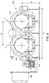
- the roller wheels 105 of the powered roller stand 100 (shown in FIG. 3 ) have the same diameter and rotate about centers that are vertically aligned with one another.
- the center-to-center distance (dimension "B") is slightly larger than the diameter of the roller wheels 105, creating a small gap between the roller wheels 105.
- the roller wheels 105 of the powered roller stand 100 are coupled to an electrical motor 116 driven from an electrical enclosure 120.
- a dimension "A" across the bottom of the roller wheel set 102 may be about 49 inches.
- a conventional diameter of the roller wheels 105, 155 is about 22 inches, and a conventional gap distance is about 1 inch, resulting in a dimension B of about 23 inches.
- a dimension "C” from the bottom of the roller wheel set 102 to the center of the rotor wheels 105 may vary between about 16 inches and about 19 inches.
- a dimension "D,” which represents an offset between the roller wheel 105 and a hub 110, is typically about 3 inches.
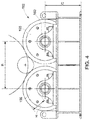
- the roller wheels 155 of the roller wheel set 152 of the idler roller stand 150 have the same diameter as one another and as the roller wheels 105 of the powered roller stand 100.
- the roller wheels 155 also define a gap between the roller wheels 155.
- the roller wheels 155 are idler rollers, meaning that their motion is driven by the rotation of the rotor shaft 22, which is driven by the rotation of the roller wheels 105 of the powered roller stand 100.
- the offset between the idler roller wheels 155 and a hub 160, represented as dimension "H" is typically between 6.5 inches and 7.5 inches.
- the centerline of the shaft 22 be level (in most cases, parallel to the floor) to prevent the rotor shaft 22 from shifting on, and perhaps falling off, the roller stands 100, 150 when the rotor shaft 22 is spun at low speeds by the powered roller stand 100.
- the shaft 22 is level when the forward journal bearing 40 and the aft journal bearing 50 are vertically aligned.
- FIG. 5 illustrates one aspect of the present alignment system 1000 (see also FIG. 16 ), which may be used to ensure the alignment of the roller stands 100, 150, thereby ensuring the alignment of the centerline of the rotor shaft 22 being supported by the roller stands 100, 150.
- the system 1000 includes a laser transmission unit 200, which is disposed on one of the roller stands (either 100 or 150), and a target unit 300, which is disposed on the other of the roller stands (either 150 or 100, respectively).
- the laser transmission unit 200 is mounted to the roller wheels 155 of the idler roller stand 150, while the target unit 300 is mounted to the roller wheels 105 of the powered roller stand 100.
- the laser transmission unit 200 includes a laser 270 that projects a laser beam 275 over a distance L to the target unit 300.
- the laser beam 260 strikes a defined point (i.e., a center) on the target unit 300, as described further below, and the technician is provided with at least a visual indicator of the successful alignment.
- the laser beam 260 produces a full circle of light at the center of the target.
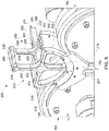
- FIG. 6 illustrates the laser transmission unit 200, as mounted on the roller wheel set 152 of the roller stand 150.
- the laser transmission unit 200 includes a front plate 210, a back plate 220 axially spaced from the front plate 210, and an arcuate panel 230 extending axially between the front plate 210 and the back plate 220 and engaging the roller wheels 155.
- the arcuate panel 230 may span a 180-degree arc, thus defining a semi-circular profile.
- the front plate 210 which faces the target unit 300, includes an arcuate portion 212, a transverse cross-piece 214 connected at each end to the arcuate portion 212, and a vertical portion 216 extending perpendicularly to the transverse cross-piece 214.
- the vertical portion 216 has a first (proximal) end 217 connected to a midpoint of the arcuate portion 212 and a second (distal) end 218 spaced apart from the transverse cross-piece 214.
- the intersection of the transverse cross-piece 214 and the vertical portion 216 forms a generally diamond-shaped region 215 through which a small laser transmission hole 213 is defined.
- the laser transmission hole 213 has a uniform diameter through the front plate 210.
- the generally diamond-shaped region 215 may be produced by defining concave curves between the respective segments of the transverse cross-piece 214 and the vertical portion 216.
- the front plate 210 is removably attached (for example, using screws at the respective ends of the transverse cross-piece 214) to the arcuate panel 230.
- the back plate 220 whose profile is congruent with the front plate 210, includes an arcuate portion 222, a transverse cross-piece 224 connected at each end to the arcuate portion 222, and a vertical portion 226 extending perpendicularly to the transverse cross-piece 224.
- the arcuate portion 222 spans the same arc (e.g., a semi-circle) as the arcuate portion 212 of the front plate 210, and the transverse cross-piece 224 has the same dimension in the transverse direction as the transverse cross-piece 214 of the front plate 210.
- the transverse cross-piece 224 and the vertical portion 226 intersect at a generally diamond-shaped region 225, which is produced by defining concave curves between the respective segments of the transverse cross-piece 224 and the vertical portion 226.
- the generally diamond-shaped region 225 defines an opening 223 therethrough for holding the laser 270.
- a support collar 221 may project outwardly from the rear surface of the back plate 220 around the perimeter of the opening 223, such that the laser 270 extends through the support collar 221 and the opening 223 and is aligned with the laser transmission hole 213.
- the opening 223 and the support collar 221 define a square shape, but other shapes may be used to accommodate lasers 270 having different cross-sectional profiles.
- the back plate 220 is removably attached (for example, using screws at the respective ends of the transverse cross-piece 224) to the arcuate panel 230 opposite the front plate 210.
- the laser 270 is a single dot, Class IIIA type laser, which may emit either red or green light and which may be provided with an adjustable beam diameter (via an aperture).
- This lightweight laser 270 may be battery operated and may transmit a laser beam over distances of up to 100 feet.
- Class IIIA lasers are relatively safe for eye exposure and are not a skin or materials burn hazard. However, typical safety precautions should be followed when the laser 270 is operational, including avoiding direct eye exposure to the laser beam 275, avoiding looking directly into reflections of the laser beam 275, and avoiding viewing the laser beam 275 with optical or magnifying devices or equipment.
- An exemplary, non-limiting laser device 270 for this purpose is the Model L100M, series MX Laser Precision Level, which is commercially available from Laser Tools Co., Inc., of Little Rock, Arkansas, although comparable devices may be available from other manufacturers.
- a distal end 228 of the vertical portion 226 of the back plate 220 is coupled to the distal end 218 of the vertical portion 216 of the front plate 210, using a spacer block 240 secured with screws or other fasteners.
- the spacer block 240 may rest upon, or interlock with, a first ledge 219 projecting from the rear surface of the distal end 218 of the vertical portion 216 of the front plate 210 and/or a second ledge 229 projecting from the front surface of the distal end 228 of the vertical portion 226 of the back plate 220.
- the laser alignment unit 200 further includes a front locking plate 250, which is removably attached to the arcuate portion 212 of the front plate 210, and a rear locking plate 252, which is removably attached to the arcuate portion 222 of the back plate 220.
- the locking plates 250, 252 are sized and shaped to secure the laser alignment unit 200 to the roller wheels 155.
- the locking plates 250, 252 may be interchanged with locking plates 250, 252 of different sizes to accommodate roller wheels 155 of different diameters and offsets.
- the laser alignment unit 200 may include a level 260 or another position detector (such as an inclinometer or tilt sensor) to assist the technician in positioning the laser alignment unit 200 squarely on the roller wheel set 152 and in achieving alignment with the target unit 300.
- the arcuate panel 230 may be provided with upwardly extending projections 232 between which the level 260 may be mounted.
- the projections 232 may extend outward from the outer surface of the arcuate panel 230 and the level 260 (or other device) may be positioned in parallel to the laser 270.
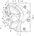
- FIG. 7 illustrates the target unit 300, as mounted on the roller wheel set 102 of the roller stand 100.
- the target unit 300 includes a front plate 310, a back plate 320 axially spaced from the front plate 310, and an arcuate panel 330 extending axially between the front plate 310 and the back plate 320 and engaging the roller wheels 105.
- the arcuate panel 330 may span a 180-degree arc, thus defining a semi-circular profile.
- the front plate 310 and the back plate 320 are removably attached to the arcuate panel 330, for example, using screws or other fasteners.
- the front plate 310 which faces the laser alignment unit 200, includes a primary arcuate portion 312, a transverse cross-piece 314 connected at each end to the arcuate portion 312, a vertical portion 316 extending perpendicularly to the transverse cross-piece 314, and a secondary arcuate portion 319 having a smaller diameter than the primary arcuate portion 312.
- the vertical portion 316 has a first end 317 connected to a midpoint of the primary arcuate portion 312 and a second end 318 connected to an intersection region 315 at the midpoint of the transverse cross-piece 314.
- the primary arcuate portion 312 defines a semi-circular shape that opens away from the roller wheels 105, while the secondary arcuate portion 319 defines a semi-circular shape that opens in the direction of the roller wheels.
- the secondary arcuate portion 319 is connected at each end to the transverse cross-piece 314 and is centered with the vertical portion 316 and may define an opening 311 between an outermost edge of the secondary arcuate portion 319 and the transverse cross-piece 314.
- the opening 311, which may also be semi-circular or arcuate, may enable the secondary arcuate portion 319 to function as a handle to facilitate carrying the target unit 300.
- intersection of the transverse cross-piece 314, the vertical portion 316, and the secondary arcuate portion 319 forms a generally pentagonal region 315 through which a small laser transmission hole 313 is defined.
- the intersection region 315 may be produced by defining concave curves between the respective segments of the transverse cross-piece 314 and the vertical portion 316.
- the rear surface of the intersection region 315 is provided with a recess area 315b.
- the intersection region 315 has a first thickness T1 at its perimeter, the thickness T1 being equal to the thickness of the transverse cross-piece 314 and the vertical portion 316.
- the intersection region 315 tapers inwardly from the rear surface 315a to a recess area 315b of uniform diameter D1.
- the surface 315c at the base of the recess area 315b is axially spaced from a front surface 315d of the intersection region 315, such that the center of the intersection region 315 (having a diameter equal to diameter D1 of the recess area 315b) has a thickness T2, which is significantly less than the thickness T1 of the intersection region 315 at its perimeter.
- the laser transmission hole 313 defined through the intersection region has a first diameter D2 on the front surface 315d of the front plate 310 and a second, larger diameter D3 on the rear surface 315c defined by the recess area 315b, thereby creating a generally conical hole.
- the laser transmission hole 313 has a funnel shape, in which the hole 313 having a first diameter D2 extends inwardly from the front surface 315d for a short distance T3 (e.g., 0.125 inches) before the diameter begins to increase uniformly to a second diameter D3 on the rear surface 315c.
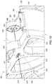
- the alignment system 1000 By providing the intersecting region 315 with a thin wall thickness (that is, the T3 distance described above) at the location of the laser transmission hole 313, the alignment system 1000 produces more accurate measures of the pitch and yaw of the roller stand(s) 100 and/or 150. Moreover, the conical shape of the hole 313, as the diameter increases from D2 to D3, ensures that the laser beam 275 will pass unimpeded through the front plate 310.
- the target unit 300 further includes a back plate 320.
- the back plate 320 is a solid plate having a primary arcuate portion 322 and a secondary arcuate portion 329 continuous and integral with the primary arcuate portion 322.
- the primary arcuate portion 322 has a generally semi-circular profile that corresponds to the shape of the arcuate panel 330.
- the secondary arcuate portion 329 likewise has a generally semi-circular profile, in which the radius of the semi-circle is smaller than that of the primary arcuate portion 322.
- the primary arcuate portion 322 is oriented in a first direction, while the secondary arcuate portion 329 is oriented in an opposite second direction.
- the profiles of the front plate 310 and the back plate 320 are congruent.
- a forward surface of the back plate 320 includes a target 324 that is engraved, printed, or otherwise produced thereon.
- a center 325 of the target 324 aligns with the laser transmission hole 313, such that a laser beam 275 passing directly through the laser transmission hole 313 strikes the center 325 of the target 324.
- the technician performing the alignment recognizes that further adjustments to the roller stand(s) 100, 150 are required.
- the target unit 300 further includes a front locking plate 350 (as in FIGS. 7 and 10 ), which is removably attached to the arcuate portion 312 of the front plate 310, and a rear locking plate 352 (as in FIG. 9 ), which is removably attached to the arcuate portion 322 of the back plate 320.
- the locking plates 350, 352 are sized and shaped to secure the target unit 300 to the roller wheels 105.
- the locking plates 350, 352 may be interchanged with locking plates 350, 352 of different sizes to accommodate roller wheels 105 of different diameters and offsets.
- the target unit 300 may include a level 360 or another position detector (such as an inclinometer or tilt sensor) to assist the technician in positioning the target unit 300 squarely on the roller wheel set 102 and in achieving alignment with the laser transmission unit 200.
- the arcuate panel 330 may be provided with upwardly extending projections 332 between which the level 360 may be mounted.
- the projections 332 may extend outward from the outer surface of the arcuate panel 330 and the level 360 (or other device) may be positioned in parallel to the path of the laser beam 275, when the units 200, 300 are aligned.
- FIG. 11 provides a flowchart of an exemplary process 400-1 for using the laser transmission unit 200 and the target unit 300 of the present alignment system 1000.
- the laser beam 275 from the laser transmission unit 200 is directed toward the target 324 of the target unit 300.
- the target 324 is checked to determine if the laser beam 275 is perfectly aligned with the center 325 of the target 324.
- the alignment units 200, 300 may be removed from the respective roller stands 100, 150, and the roller stands 100, 150 are ready to receive the rotor 22.
- the technician manually adjusts the position of the roller stand (e.g., stand 100) to which the laser transmission unit 200 is mounted.
- the roller stand e.g., stand 100
- FIGS. 12 and 13 illustrate an automated version of the present alignment system 1000, which uses a laser beam sensing screen 380 attached to the back plate 320 of the target unit 300.
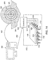
- the laser beam sensing screen 380 is in electronic communication with a computing device 390 (e.g., a computer or tablet computer), as shown in FIG. 14 .
- a computing device 390 e.g., a computer or tablet computer
- a conical mirror 370 is mounted between the front plate 310 and the back plate 320 of the target unit 300 (mounting hardware not shown).
- the conical mirror 370 has a reflective body 372, a tip 374, and a base 376 opposite the tip.
- An aperture 375 extends through the reflective body 372 from the tip 374 to the base 376.
- the conical mirror 370 may be hollow, and the base 376 may instead be a plane that defines the base of the conical shape of the reflective body 372.
- the tip 374 When installed, the tip 374 is proximate to the front plate 310, the base (or base plane) 376 is proximate to the back plate 320, and the aperture 375 is aligned with the laser transmission hole 313 in the front plate 310 and the center 325 of the target 324 on the back plate 320.
- the aperture 375 provides a passage for the laser beam 275 to reach the center 325 of the target 324 (as shown in FIG. 12 ).
- the laser beam 275 when the laser beam 275 is not aligned with the center 325 of the target 324 (as shown in FIG. 13 ), the laser beam 275 reflects off the reflective body 372 of the conical mirror 370. The reflected laser beam 275' makes contact with the laser beam sensing screen 380 at a sensed position 280.
- the laser beam sensing screen 380 communicates the sensed position(s) 280 of the reflected laser beams 275' as one or more signals 382, which are transmitted (wirelessly or through wired connections) to a computing device 390 (such as a computer or tablet computer).
- the computing device 390 is programmed to convert the signal(s) 382 to determine the axial trajectory of the laser beam 275 (see FIG. 15 ), as the laser beam 275 exits the laser transmission hole 313 in the front plate 310.
- the axial trajectory of the laser beam 275 may be plotted on a data display 600 presented by the computing device 390 for viewing by the technician (see FIG. 15 ).
- the laser beam sensing screen 280 may be used without the conical mirror 370. In these instances, the laser beam 275 is directed through the laser transmission hole 313 in the front plate 310 and strikes the laser beam sensing screen 280 directly.
- the laser beam sensing screen 380 may transmit a signal 382 to the computing device 390 to determine whether the laser beam 275 is aligned with the center 325 of the target 324.
- the computing device 390 may be in electronic communication with a control unit 500 for a hydraulically actuated roller stand platform 108.
- the roller stand platform 108 may be positioned beneath the stand elements 104, 106, or may replace one of or both the stand elements 104, 106 (shown in FIG. 5 ).
- the roller stand platform 108 may include a first set of hydraulic cylinders 510, a second set of hydraulic cylinders 520, and a third set of hydraulic cylinders 530.
- the first set of hydraulic cylinders 510 are positioned at the corners of the roller stand platform 108 and are used to adjust the vertical height of the roller stand platform 108.
- the second set of hydraulic cylinders 520 are spaced along a first pair of opposing sides of the roller stand platform 108 and are used to adjust the axial position of the roller stand platform 108.
- the third set of hydraulic cylinders 530 are spaced along a second pair of opposing sides of the roller stand platform 108 and are used to adjust the transverse position of the roller stand platform 108.
- the number of cylinders in each set may vary from the number illustrated in the exemplary drawing.
- the control unit 500 transmits signals 512, 522, 532 to the individual hydraulic cylinders of the first set of hydraulic cylinders 510, the second set of hydraulic cylinders, and the third set of hydraulic cylinders 530, respectively.
- Each hydraulic cylinder of the sets 510, 520, 530 may be independently operated to achieve a full range of motion in the X-Y-Z directions (i.e., axially, vertically, and transversely).
- roller stand platform 108 is advantageously used in conjunction with the roller stand 100, 150 on which the laser transmission unit 200 is mounted.
- both the roller stand 100 and the roller stand 150 may be provided with a hydraulically actuated roller stand platform 108.
- FIG. 15 provides a flowchart of a second exemplary process 400-2 for using the laser transmission unit 200 and the target unit 300 of the present alignment system 1000.
- the laser beam 275 from the laser transmission unit 200 is directed toward the target 324 of the target unit 300.
- the target 324 is checked to determine if the laser beam 275 is perfectly aligned with the center 325 of the target 324. This step may be performed manually by the technician or automatically by the computer 390 based on signals 382 from the laser beam sensing screen 380.
- step 460 if the laser beam 275 is perfectly aligned with the center 325 of the target 324, then the alignment units 200, 300 may be removed from the respective roller stands 100, 150, and the roller stands 100, 150 are ready to receive the rotor 22.
- a plot 610 of the axial trajectory 615 of the laser beam 275 relative to the center 325 of the target 324 is produced, using a computer 390 (or similar computing device, such as a tablet computer) configured with a program for such purpose.
- the position of the laser beam 275 may be ascertained, based on its axial trajectory, using data provided by the laser beam sensing screen 280 (shown in FIGS. 12 and 13 ).
- the plot 610 of the position 615 of the laser beam 275, relative to the center 625 of a simulated target 620 may be part of a visual data display 600, viewable on the computer 390 (or another device, such as a tablet computer).
- the visual data display 600 may further include a quantification 630 of the position of the laser beam 275 and bibliographic information 640, such as the date and time of the measurement and identifying information for the engine from which the rotor 22 is taken.
- step 440 if the laser beam 275 is not perfectly aligned with the center 325 of the target 324, the computer 390 transmits instructions 392 to the control unit 500 of the hydraulically actuated roller stand platform 108.
- step 450 one or more of the first set of hydraulic cylinders 510, the second set of hydraulic cylinders 520, and the third set of hydraulic cylinders 530 adjusts the position of the roller stand platform 108 (e.g., supporting roller stand 100) to which the laser transmission unit 200 is mounted.
- the roller stand platform 108 e.g., supporting roller stand 100
- the process 400-2 repeats until the laser beam 275 is aligned with the center 325 of the target 324.
- FIG. 16 illustrates the present alignment system 1000, which includes the laser alignment unit 200 and the target unit 300.
- the system 1000 may further include a computer 390 (or other computing device), a control unit 500 in electronic communication with the computer 390, and a hydraulically actuated roller stand platform 108 with sets of hydraulic cylinders 510, 520, 530 in electronic communication with the control unit 500.
- the target unit 300 may be provided with a laser beam sensing screen 380 applied to the back plate 320 to detect the position of the laser beam 275. Further still, the target unit 300 may include a conical mirror 370 positioned between the front plate 310 and the back plate 320.
- the laser alignment unit 200 and the target unit 300 may have components (e.g., front plate, back plate, arcuate panel that are separate components joined together by fasteners, such as screws or interlocking tabs.
- the components may be produced from plastic or metal using additive manufacturing techniques or conventional methods, such as casting, molding, or other fabrication techniques.
- the present alignment system and method significantly reduce the time, effort, and manpower required to successfully align a pair of opposing roller stands, so that a gas turbine rotor may be inspected or serviced external to the gas turbine casing.
- the laser transmission unit and the target unit includes components that are readily joined together and to the respective roller stands.
- the laser transmission unit and the target unit are lightweight and readily portable. A single technician is able to perform the alignment method using the present alignment system in a matter of minutes, in sharp contrast to the multiple hours required for two technicians to complete an alignment using conventional techniques.
Landscapes
- Engineering & Computer Science (AREA)
- Physics & Mathematics (AREA)
- General Physics & Mathematics (AREA)
- Mechanical Engineering (AREA)
- General Engineering & Computer Science (AREA)
- Length Measuring Devices By Optical Means (AREA)
Abstract
Description
- The present disclosure relates generally to the field of alignment equipment and, more specifically, to a system and method that use a laser beam to align the shaft centerline of rotating equipment, such as a gas turbine rotor. According to one aspect provided herein, the rotor is supported by oppositely disposed roller stands, and the position of at least one of the roller stands may be adjusted such that a laser beam originating from one roller stand contacts the center of a target on an opposing roller stand. In one embodiment, the adjustment of the roller stand is performed automatically using hydraulic cylinders coupled to a control unit that receives data about the position of the laser beam relative to the target.
- Some conventional turbo machines, such as gas turbine systems, are utilized to generate electrical power. In general, gas turbine systems include a compressor, one or more combustors, and a turbine. Air may be drawn into a compressor, via its inlet, where the air is compressed by passing through multiple stages of rotating blades and stationary nozzles. The compressed air is directed to the one or more combustors, where fuel is introduced, and a fuel/air mixture is ignited and burned to form combustion products. The combustion products function as the operational fluid of the turbine.
- The operational fluid then flows through a fluid flow path in a turbine, the flow path being defined between a plurality of rotating blades and a plurality of stationary nozzles disposed between the rotating blades, such that each set of rotating blades and each corresponding set of stationary nozzles defines a turbine stage. As the plurality of rotating blades rotate the rotor of the gas turbine system, a generator, coupled to the rotor, may generate power from the rotation of the rotor. The rotation of the turbine blades also causes rotation of the compressor blades, which are coupled to the rotor.
- Conventionally, during maintenance, a gas turbine rotor may be removed from the gas turbine casing and supported on each end by a roller system to permit inspection and servicing of the rotor, the compressor blades, and/or the turbine blades. The roller system may include a powered roller stand and an idler roller stand. It is necessary to position the rotor stands to achieve perfect alignment of the rotor centerline within the roller stands to prevent the rotor from moving axially ("walking") off the roller stands, as the rotor is rotated at slow speeds. With perfect alignment, the rotor journal bearing surfaces are level and aligned with each other. If the rotor is not perfectly aligned within the roller stands, the technicians are required to stop their inspection or maintenance processes and re-align the roller stands, which is a time-consuming process.
- This problem of properly aligning the rotor within the roller stands is challenging due to the weight and length of the rotor. Conventionally, the alignment process has required the skills of two technicians, using rudimentary tools such as tape measures, to measure the alignment of the roller stands and to adjust the roller stands, using shims, until the desired perfect alignment is achieved. In some instances, this process could occupy the time of the two technicians for as long as eight hours.
- An alignment system and method for aligning the shaft centerline of rotating equipment positioned on opposing roller stands are provided. The system includes a laser transmission unit on the first stand and a target unit on the second stand. The laser transmission unit includes a laser that transmits a laser beam to a target on the target unit. When the laser beam contacts the center of the target, the roller stands are aligned. The system may be automated to detect the position of the laser beam relative to the target center and to adjust, as needed, the position of one of or both the roller stands using hydraulic cylinders coupled to a roller stand platform. The system and method reduce the time, effort, and manpower required to perform the alignment.
- More specifically, according to one aspect provided herein, an alignment system for aligning the shaft centerline of rotating equipment positioned on opposing roller stands. The alignment system includes a laser transmission unit configured for engagement with a first roller stand and a target unit configured for engagement with a second roller stand axially spaced from the first roller stand. The laser transmission unit includes a first front plate defining a first laser transmission hole therethrough, a first back plate axially spaced from the first front plate, a first arcuate panel extending axially between the first front plate and the first back plate and being configured to contact a first pair of roller wheels of the first roller stand, and a laser centrally mounted through the first back plate and extending to the first front plate, such that a laser beam produced by the laser is transmitted through the first laser transmission hole of the first front plate. The target unit includes a second front plate defining a second laser transmission hole therethrough, a second back plate axially spaced from the second front plate and being provided with an image of a target, the target having a center aligned with the second laser transmission hole, and a second arcuate panel extending axially between the second front plate and the second back plate and being configured to contact a second pair of roller wheels of the second roller stand. When a laser beam from the laser transmission unit passes through the second laser transmission hole of the second front plate and reaches the center of the target on the second back plate, the first roller stand and the second roller stand are aligned.
- According to another aspect provided herein, a method of aligning the heights of opposing roller stands is provided. The alignment method includes: positioning a laser transmission unit on a first roller stand and a target unit on a second roller stand; directing a laser beam from the laser transmission unit to the target unit; determining a location at which the laser beam contacts the second back plate of the target unit; and adjusting a position of the first roller stand until the laser beam contacts the center of the target. The laser transmission unit includes a first front plate defining a first laser transmission hole therethrough, a first back plate axially spaced from the first front plate, a first arcuate panel extending axially between the first front plate and the first back plate and being configured to contact a first pair of roller wheels of the first roller stand, and a laser centrally mounted through the first back plate and extending to the first front plate, such that a laser beam produced by the laser is transmitted through the first laser transmission hole of the first front plate. The target unit includes a second front plate defining a second laser transmission hole therethrough, a second back plate axially spaced from the second front plate and being provided with an image of a target, the target having a center aligned with the second laser transmission hole, and a second arcuate panel extending axially between the second front plate and the second back plate and being configured to contact a second pair of roller wheels of the second roller stand.
- Certain aspects of the herein disclosed subject matter are outlined below.
- Disclosed is an alignment system comprising a laser transmission unit configured for engagement with a first roller stand, the laser transmission unit comprising a first front plate defining a first laser transmission hole therethrough, a first back plate axially spaced from the first front plate, a first arcuate panel extending axially between the first front plate and the first back plate and being configured to contact a first pair of roller wheels of the first roller stand, and a laser centrally mounted through the first back plate and extending to the first front plate, such that a laser beam produced by the laser is transmitted through the first laser transmission hole of the first front plate, and a target unit configured for engagement with a second roller stand axially spaced from the first roller stand, the target unit comprising a second front plate defining a second laser transmission hole therethrough, a second back plate axially spaced from the second front plate and being provided with an image of a target, the target having a center aligned with the second laser transmission hole and a second arcuate panel extending axially between the second front plate and the second back plate and being configured to contact a second pair of roller wheels of the second roller stand, wherein, when a laser beam from the laser transmission unit passes through the second laser transmission hole of the second front plate and reaches the center of the target on the second back plate, the first roller stand and the second roller stand are aligned.
- In a more specific exemplary embodiment, in a system as described in the preceding paragraph the first front plate and the first back plate each comprise a first arcuate portion having a shape matching a first profile of the first arcuate panel, wherein a transverse cross-piece extends across the first arcuate portion, and a vertical portion extends from a midpoint of the first arcuate portion through the midpoint of the transverse cross-piece, thereby forming an intersection region. The first laser transmission hole is defined through the intersection region of the first front plate and the laser being mounted through the intersection region of the first back plate.
- The system of any preceding claim, wherein the first back plate defines an opening through which the laser is mounted; and wherein a support collar extends from a rear surface of the back plate around the opening, the support collar being configured to hold the laser.
- The vertical portion of the first front plate and the vertical portion of the first back plate may extend beyond the intersection region; and a spacer block may extend axially between an end of the vertical portion of the first front plate and a respective end of the vertical portion of the first back plate.
- In exemplary embodiments the laser is a single-dot, Class IIIA laser.
- In exemplary embodiments the first laser transmission hole has a uniform diameter.
- In more specific exemplary embodiments the laser transmission unit further comprises a first front locking plate and a first rear locking plate, the first front locking plate being removably coupled to the first front plate and the first rear locking plate being removably coupled to the first back plate.
- The laser transmission unit further may comprise a first level attached to the first arcuate panel.
- In certain exemplary embodiments the second front plate of the target unit comprises a second arcuate portion having a shape matching a second profile of the second arcuate panel, a transverse cross-piece extending across the second arcuate portion, and a vertical portion extending from a midpoint of the second arcuate portion to the transverse cross-piece, thereby forming an intersection region, wherein the second laser transmission hole is defined through the intersection region of the second front plate.
- It may be provided that the intersection region of the second front plate comprises a perimeter having a first thickness. A recessed area is provided radially inward of the perimeter and extends axially inward from a rear surface of the intersection region and a central area extends axially between the recessed area and a front surface of the intersection region. The central area has a second thickness less than the first thickness. The second laser transmission hole is defined through the central area.
- The second laser transmission hole may comprise a cylindrical hole portion having a first diameter and extending inwardly from the front surface and a conical hole portion whose diameter increases from the first diameter to a second diameter at the rear surface of the intersection region, thereby defining a funnel-shaped hole.
- In aspects, the second back plate of the target unit comprises a primary arcuate portion and a secondary arcuate portion integral with the primary arcuate portion, the primary arcuate portion having a shape and a first diameter corresponding to a profile of the second arcuate panel, and the secondary arcuate portion having a second diameter smaller than the first diameter; and wherein the target is disposed across the primary arcuate portion and the secondary arcuate portion.
- It may further be optionally provided that the target unit further comprises a second front locking plate and a second rear locking plate, the second front locking plate being removably coupled to the second front plate and the second rear locking plate being removably coupled to the second back plate.
- In exemplary embodiments it may be provided that a laser beam sensing screen is disposed over a front surface of the second back plate, the laser beam sensing screen being configured to detect a location at which the laser beam contacts laser beam sensing screen; and a computing device configured to receive signals from the laser beam sensing screen and to quantify the location relative to the center of the target.
- The system may further comprise a conical mirror disposed between the second front plate and the second back plate of the target unit, the conical mirror having a reflective body with a tip and a base, the reflective body defining an aperture extending through the tip and the reflective body along a longitudinal axis of the conical mirror. The conical mirror may be oriented such that the tip is proximate to the front plate of the target unit and the base is proximate to the back plate of the target unit. It may be provided that, when the laser beam strikes the conical mirror at a location other than the aperture, the reflective body deflects the laser beam onto the laser beam sensing screen.
- A roller stand platform is, in exemplary embodiments, disposed beneath at least one of the first roller stand and the second roller stand; and wherein the system further comprises, disposed beneath and in contact with the roller stand platform, a first plurality of hydraulic cylinders configured to adjust a vertical height of the roller stand platform, a second plurality of hydraulic cylinders configured to adjust an axial position of the roller stand platform, and a third plurality of hydraulic cylinders configured to adjust a transverse position of the roller stand platform.
- A control unit may be provided and configured to receive instructions from the computing device and to communicate the instructions to each of the first plurality of hydraulic cylinders, the second plurality of hydraulic cylinders, and the third plurality of hydraulic cylinders, the control unit being in communication with and responsive to position signals from the laser beam sensing screens.
- In other aspects a method of aligning the heights of opposing roller stands is disclosed. The method comprises positioning a laser transmission unit on a first roller stand and a target unit on a second roller stand, wherein the laser transmission unit comprises a first front plate defining a first laser transmission hole therethrough, a first back plate axially spaced from the first front plate, a first arcuate panel extending axially between the first front plate and the first back plate and being configured to contact a first pair of roller wheels of the first roller stand, and a laser centrally mounted through the first back plate and extending to the first front plate, such that a laser beam produced by the laser is transmitted through the first laser transmission hole of the first front plate. The target unit comprises a second front plate defining a second laser transmission hole therethrough, a second back plate axially spaced from the second front plate and being provided with an image of a target, the target having a center aligned with the second laser transmission hole. A second arcuate panel extends axially between the second front plate and the second back plate and being configured to contact a second pair of roller wheels of the second roller stand. The method further comprises directing a laser beam from the laser transmission unit to the target unit, determining a location at which the laser beam contacts the second back plate of the target unit; and adjusting a position of the first roller stand until the laser beam contacts the center of the target.
- In more specific aspects of the method determining a location at which the laser beam contacts the target unit comprises receiving, in a computing device, a signal from a laser beam sensing screen disposed over a front surface of the second back plate of the target unit and quantifying the location at which the laser beam contacts the target unit, using the computing device.
- Adjusting a position of the first roller stand may comprise communicating instructions from the computing device to a control unit in electronic communication with a roller stand platform disposed beneath the first roller stand; wherein the roller stand platform comprises a first plurality of hydraulic cylinders configured to adjust a vertical height of the roller stand platform, a second plurality of hydraulic cylinders configured to adjust an axial position of the roller stand platform, and a third plurality of hydraulic cylinders configured to adjust a transverse position of the roller stand platform; and wherein the control unit communications the instructions to each of the first plurality of hydraulic cylinders, the second plurality of hydraulic cylinders, and the third plurality of hydraulic cylinders.
- It is understood that the embodiments and features of the system and the method disclosed above may be readily combined with each other.
- The specification, directed to one of ordinary skill in the art, sets forth a full and enabling disclosure of the present system and method, including the best mode of using the same. The specification refers to the appended figures, in which:
-
FIG. 1 is a functional block diagram of an exemplary gas turbine that may incorporate various embodiments of the present disclosure; -
FIG. 2 is perspective view of a gas turbine rotor positioned on a pair of oppositely disposed roller stands, according to one aspect of the present disclosure; -
FIG. 3 is a forward-looking-aft view of a roller wheel set of a powered roller stand ofFIG. 2 ; -
FIG. 4 is a forward-looking-aft view of a roller wheel set of an idler roller stand ofFIG. 2 ; -
FIG. 5 is a perspective view of the roller stands ofFIGS. 2 through 4 and an alignment system of the present disclosure, illustrating the alignment of a laser beam from a laser transmitting unit positioned on a first roller stand to a target unit positioned on a second roller stand, according to an aspect of the present disclosure; -
FIG. 6 is a perspective view of the laser transmitting unit ofFIG. 5 ; -
FIG. 7 is a perspective view of the target unit ofFIG. 5 ; -
FIG. 8 is an aft-looking-forward perspective view of a portion of the target unit ofFIGS. 5 and7 , illustrating the transmission of a laser beam through a forward plate of the target unit; -
FIG. 9 is an enlarged, partial cross-sectional view of the target unit ofFIGS. 5 ,7 , and8 , illustrating the alignment of a laser beam through the forward plate of the target unit; -
FIG. 10 is a forward-looking-aft perspective view of a laser beam being transmitted through the target unit ofFIGS. 5 and7-9 ; -
FIG. 11 is a flow diagram describing the use of the laser transmitting unit and the target unit of the present alignment system, according to one aspect provided herein; -
FIG. 12 is a perspective view of an alternate embodiment of the target unit ofFIG. 7 , further including a conical mirror and a laser beam sensing screen, in which the laser beam is aligned with a target of the target unit; -
FIG. 13 is a perspective view of the alternate embodiment ofFIG. 12 , in which the laser beam is misaligned with the target of the target unit; -
FIG. 14 is a schematic representation of another aspect of the present alignment system, in which signals from the laser beam sensing screen ofFIG. 12 are processed by a computer and in which the computer provides signals to a control unit for actuation of hydraulic cylinders coupled to a roller stand platform; -
FIG. 15 is a flow diagram describing the process of automatically adjusting the position of the roller stand using hydraulic cylinders, as shown inFIG. 14 ; and -
FIG. 16 illustrates the various components of the present alignment system, as described herein. - Reference will now be made in detail to various embodiments of the present disclosure, one or more examples of which are illustrated in the accompanying drawings. The detailed description uses numerical and letter designations to refer to features in the drawings. Like or similar designations in the drawings and description have been used to refer to like or similar parts of the disclosure.
- To clearly describe the current laser alignment system, certain terminology will be used to refer to and describe relevant machine components within the scope of this disclosure. To the extent possible, common industry terminology will be used and employed in a manner consistent with the accepted meaning of the terms. Unless otherwise stated, such terminology should be given a broad interpretation consistent with the context of the present application and the scope of the appended claims. Those of ordinary skill in the art will appreciate that often a particular component may be referred to using several different or overlapping terms. What may be described herein as being a single part may include and be referenced in another context as consisting of multiple components. Alternatively, what may be described herein as including multiple components may be referred to elsewhere as a single integrated part.
- In addition, several descriptive terms may be used regularly herein, as described below. The terms "first", "second", and "third" may be used interchangeably to distinguish one component from another and are not intended to signify location or importance of the individual components.
- As used herein, "downstream" and "upstream" are terms that indicate a direction relative to the flow of a fluid, such as the working fluid through the turbine engine. The term "downstream" corresponds to the direction of flow of the fluid, and the term "upstream" refers to the direction opposite to the flow (i.e., the direction from which the fluid flows). The terms "forward" and "aft," without any further specificity, refer to relative position, with "forward" being used to describe components or surfaces located toward the front (or compressor) end of the engine or toward the inlet end of the combustor, and "aft" being used to describe components located toward the rearward (or turbine) end of the engine or toward the outlet end of the combustor. The terms "inner" or "proximal" are used to describe components in proximity to the turbine shaft, while the terms "outer" or "distal" are used to describe components distal to the turbine shaft.
- It is often required to describe parts that are at differing radial, axial and/or circumferential positions. As shown in
FIG. 1 , the "A" axis represents an axial orientation. As used herein, the terms "axial" and/or "axially" refer to the relative position/direction of objects along axis A, which is substantially parallel with the axis of rotation of the gas turbine system. As further used herein, the terms "radial" and/or "radially" refer to the relative position or direction of objects along an axis "R", which intersects axis A at only one location. In some embodiments, axis R is substantially perpendicular to axis A. Finally, the term "circumferential" refers to movement or position around axis A (e.g., axis "C"). The term "circumferential" may refer to a dimension extending around a center of a respective object (e.g., a rotor). - The terminology used herein is for the purpose of describing particular embodiments only and is not intended to be limiting. As used herein, the singular forms "a", "an" and "the" are intended to include the plural forms as well, unless the context clearly indicates otherwise. It will be further understood that the terms "comprises" and/or "comprising," when used in this specification, specify the presence of stated features, integers, steps, operations, elements, and/or components, but do not preclude the presence or addition of one or more other features, integers, steps, operations, elements, components, and/or groups thereof. Each example is provided by way of explanation, not limitation. In fact, it will be apparent to those skilled in the art that modifications and variations can be made without departing from the scope or spirit thereof. For instance, features illustrated or described as part of one embodiment may be used on another embodiment to yield a still further embodiment. Thus, it is intended that the present disclosure covers such modifications and variations as come within the scope of the appended claims and their equivalents.
- Although exemplary embodiments of the present disclosure will be described generally in the context of a laser alignment system for the rotor of a land-based power-generating gas turbine for purposes of illustration, one of ordinary skill in the art will readily appreciate that embodiments of the present disclosure may be applied to the alignment of many types of devices across many industries.
- Referring now to the drawings,
FIG. 1 schematically illustrates anexemplary gas turbine 10. Thegas turbine 10 generally includes aninlet section 12, acompressor 14 disposed downstream of theinlet section 12, acombustion section 16 disposed downstream of thecompressor 14, aturbine 18 disposed downstream of thecombustion section 16, and anexhaust section 20 disposed downstream of theturbine 18. Additionally, thegas turbine 10 may include one or more shafts 22 (also known as "rotors") that couple thecompressor 14 to theturbine 18. - During operation,
air 24 flows through theinlet section 12 and into thecompressor 14, where theair 24 is progressively compressed, thus providingcompressed air 26 to thecombustion section 16. At least a portion of thecompressed air 26 is mixed with afuel 28 within thecombustion section 16 and burned to producecombustion gases 30. Thecombustion section 16 may include a circumferential array ofcombustion cans 32, two of which are illustrated inFIG. 1 , or may instead be an annular combustion system. Thecombustion gases 30 flow from thecombustion section 16 to into theturbine 18, where thermal and/or kinetic energy are transferred from thecombustion gases 30 to rotor blades (shown inFIG. 2 ) attached to theshaft 22, thereby causing theshaft 22 to rotate. The mechanical rotational energy may then be used for various purposes, such as to power thecompressor 14 and/or to generate electricity, via agenerator 21 coupled to theshaft 22. Thecombustion gases 30 exiting theturbine 18 may then be exhausted from thegas turbine 10, via theexhaust section 20. -
FIG. 2 is a perspective side view of therotor shaft 22, as removed from the gas turbine casing and supported on a pair of oppositely disposed roller stands 100, 150. Therotor shaft 22 includes acompressor section 14 with multiple (from eight to twenty) stages ofrotating blades 34 and aturbine section 18 with several (typically, three or four) stages ofrotating blades 38. A forward journal bearing 40 supports the forward end of thecompressor section 16, while an aft journal bearing 50 supports the aft end of theturbine section 18. During inspection and maintenance, thejournal bearings - The roller stand 100 may be a powered roller stand, while the roller stand 150 may be an idler roller stand. As shown, a forward (compressor) end of the
rotor shaft 22 is supported by thepowered roller stand 100, and the aft (turbine) end of therotor shaft 22 is supported by theidler roller stand 150. Such arrangement is not required; that is, therotor shaft 22 may be arranged with the forward end supported by theidler roller stand 150 and the aft end supported by thepowered roller stand 100. - As shown in
FIGS. 2 through 4 , each roller stand 100, 150 includes aroller wheel set roller wheel modules roller wheels rotor shaft 22. Theroller wheels 105 of the powered roller stand 100 (shown inFIG. 3 ) have the same diameter and rotate about centers that are vertically aligned with one another. The center-to-center distance (dimension "B") is slightly larger than the diameter of theroller wheels 105, creating a small gap between theroller wheels 105. Theroller wheels 105 of the powered roller stand 100 are coupled to anelectrical motor 116 driven from anelectrical enclosure 120. - By way of example and not of limitation, a dimension "A" across the bottom of the
roller wheel set 102 may be about 49 inches. A conventional diameter of theroller wheels rotor wheels 105 may vary between about 16 inches and about 19 inches. A dimension "D," which represents an offset between theroller wheel 105 and a hub 110, is typically about 3 inches. - Likewise, as shown in
FIG. 4 , theroller wheels 155 of the roller wheel set 152 of the idler roller stand 150 have the same diameter as one another and as theroller wheels 105 of thepowered roller stand 100. Theroller wheels 155 also define a gap between theroller wheels 155. Theroller wheels 155 are idler rollers, meaning that their motion is driven by the rotation of therotor shaft 22, which is driven by the rotation of theroller wheels 105 of thepowered roller stand 100. The offset between theidler roller wheels 155 and ahub 160, represented as dimension "H", is typically between 6.5 inches and 7.5 inches. - As discussed above, to perform routine inspection and maintenance of the
rotor shaft 22, the compressor blades 36, and theturbine blades 38, it is necessary that the centerline of theshaft 22 be level (in most cases, parallel to the floor) to prevent therotor shaft 22 from shifting on, and perhaps falling off, the roller stands 100, 150 when therotor shaft 22 is spun at low speeds by thepowered roller stand 100. Theshaft 22 is level when the forward journal bearing 40 and the aft journal bearing 50 are vertically aligned. -
FIG. 5 illustrates one aspect of the present alignment system 1000 (see alsoFIG. 16 ), which may be used to ensure the alignment of the roller stands 100, 150, thereby ensuring the alignment of the centerline of therotor shaft 22 being supported by the roller stands 100, 150. Thesystem 1000 includes alaser transmission unit 200, which is disposed on one of the roller stands (either 100 or 150), and atarget unit 300, which is disposed on the other of the roller stands (either 150 or 100, respectively). In the exemplary illustration, thelaser transmission unit 200 is mounted to theroller wheels 155 of theidler roller stand 150, while thetarget unit 300 is mounted to theroller wheels 105 of thepowered roller stand 100. - The
laser transmission unit 200 includes alaser 270 that projects alaser beam 275 over a distance L to thetarget unit 300. When the roller stands 100, 150 are aligned vertically and horizontally with one another, thelaser beam 260 strikes a defined point (i.e., a center) on thetarget unit 300, as described further below, and the technician is provided with at least a visual indicator of the successful alignment. For example, thelaser beam 260 produces a full circle of light at the center of the target. -
FIG. 6 illustrates thelaser transmission unit 200, as mounted on the roller wheel set 152 of theroller stand 150. Thelaser transmission unit 200 includes afront plate 210, aback plate 220 axially spaced from thefront plate 210, and anarcuate panel 230 extending axially between thefront plate 210 and theback plate 220 and engaging theroller wheels 155. In one embodiment, thearcuate panel 230 may span a 180-degree arc, thus defining a semi-circular profile. - The
front plate 210, which faces thetarget unit 300, includes anarcuate portion 212, atransverse cross-piece 214 connected at each end to thearcuate portion 212, and avertical portion 216 extending perpendicularly to thetransverse cross-piece 214. Thevertical portion 216 has a first (proximal)end 217 connected to a midpoint of thearcuate portion 212 and a second (distal) end 218 spaced apart from thetransverse cross-piece 214. The intersection of thetransverse cross-piece 214 and thevertical portion 216 forms a generally diamond-shapedregion 215 through which a smalllaser transmission hole 213 is defined. In one embodiment, thelaser transmission hole 213 has a uniform diameter through thefront plate 210. The generally diamond-shapedregion 215 may be produced by defining concave curves between the respective segments of thetransverse cross-piece 214 and thevertical portion 216. - The
front plate 210 is removably attached (for example, using screws at the respective ends of the transverse cross-piece 214) to thearcuate panel 230. - The
back plate 220, whose profile is congruent with thefront plate 210, includes anarcuate portion 222, atransverse cross-piece 224 connected at each end to thearcuate portion 222, and avertical portion 226 extending perpendicularly to thetransverse cross-piece 224. Thearcuate portion 222 spans the same arc (e.g., a semi-circle) as thearcuate portion 212 of thefront plate 210, and thetransverse cross-piece 224 has the same dimension in the transverse direction as thetransverse cross-piece 214 of thefront plate 210. - Like the corresponding elements of the
front plate 210, thetransverse cross-piece 224 and thevertical portion 226 intersect at a generally diamond-shapedregion 225, which is produced by defining concave curves between the respective segments of thetransverse cross-piece 224 and thevertical portion 226. The generally diamond-shapedregion 225 defines anopening 223 therethrough for holding thelaser 270. Asupport collar 221 may project outwardly from the rear surface of theback plate 220 around the perimeter of theopening 223, such that thelaser 270 extends through thesupport collar 221 and theopening 223 and is aligned with thelaser transmission hole 213. In the exemplary embodiment, theopening 223 and thesupport collar 221 define a square shape, but other shapes may be used to accommodatelasers 270 having different cross-sectional profiles. - The
back plate 220 is removably attached (for example, using screws at the respective ends of the transverse cross-piece 224) to thearcuate panel 230 opposite thefront plate 210. - In an exemplary embodiment, the
laser 270 is a single dot, Class IIIA type laser, which may emit either red or green light and which may be provided with an adjustable beam diameter (via an aperture). Thislightweight laser 270 may be battery operated and may transmit a laser beam over distances of up to 100 feet. Class IIIA lasers are relatively safe for eye exposure and are not a skin or materials burn hazard. However, typical safety precautions should be followed when thelaser 270 is operational, including avoiding direct eye exposure to thelaser beam 275, avoiding looking directly into reflections of thelaser beam 275, and avoiding viewing thelaser beam 275 with optical or magnifying devices or equipment. An exemplary,non-limiting laser device 270 for this purpose is the Model L100M, series MX Laser Precision Level, which is commercially available from Laser Tools Co., Inc., of Little Rock, Arkansas, although comparable devices may be available from other manufacturers. Adistal end 228 of thevertical portion 226 of theback plate 220 is coupled to thedistal end 218 of thevertical portion 216 of thefront plate 210, using aspacer block 240 secured with screws or other fasteners. Thespacer block 240 may rest upon, or interlock with, afirst ledge 219 projecting from the rear surface of thedistal end 218 of thevertical portion 216 of thefront plate 210 and/or asecond ledge 229 projecting from the front surface of thedistal end 228 of thevertical portion 226 of theback plate 220. - The
laser alignment unit 200 further includes afront locking plate 250, which is removably attached to thearcuate portion 212 of thefront plate 210, and arear locking plate 252, which is removably attached to thearcuate portion 222 of theback plate 220. The lockingplates laser alignment unit 200 to theroller wheels 155. The lockingplates plates roller wheels 155 of different diameters and offsets. Optionally, thelaser alignment unit 200 may include alevel 260 or another position detector (such as an inclinometer or tilt sensor) to assist the technician in positioning thelaser alignment unit 200 squarely on theroller wheel set 152 and in achieving alignment with thetarget unit 300. In the exemplary illustrated embodiment, thearcuate panel 230 may be provided with upwardly extendingprojections 232 between which thelevel 260 may be mounted. In an alternate arrangement, theprojections 232 may extend outward from the outer surface of thearcuate panel 230 and the level 260 (or other device) may be positioned in parallel to thelaser 270. -
FIG. 7 illustrates thetarget unit 300, as mounted on the roller wheel set 102 of theroller stand 100. Thetarget unit 300 includes afront plate 310, aback plate 320 axially spaced from thefront plate 310, and anarcuate panel 330 extending axially between thefront plate 310 and theback plate 320 and engaging theroller wheels 105. In one embodiment, thearcuate panel 330 may span a 180-degree arc, thus defining a semi-circular profile. Thefront plate 310 and theback plate 320 are removably attached to thearcuate panel 330, for example, using screws or other fasteners. - The
front plate 310, which faces thelaser alignment unit 200, includes a primaryarcuate portion 312, atransverse cross-piece 314 connected at each end to thearcuate portion 312, avertical portion 316 extending perpendicularly to thetransverse cross-piece 314, and a secondaryarcuate portion 319 having a smaller diameter than the primaryarcuate portion 312. Thevertical portion 316 has afirst end 317 connected to a midpoint of the primaryarcuate portion 312 and asecond end 318 connected to anintersection region 315 at the midpoint of thetransverse cross-piece 314. - The primary
arcuate portion 312 defines a semi-circular shape that opens away from theroller wheels 105, while the secondaryarcuate portion 319 defines a semi-circular shape that opens in the direction of the roller wheels. The secondaryarcuate portion 319 is connected at each end to thetransverse cross-piece 314 and is centered with thevertical portion 316 and may define anopening 311 between an outermost edge of the secondaryarcuate portion 319 and thetransverse cross-piece 314. Theopening 311, which may also be semi-circular or arcuate, may enable the secondaryarcuate portion 319 to function as a handle to facilitate carrying thetarget unit 300. - An intersection of the
transverse cross-piece 314, thevertical portion 316, and the secondaryarcuate portion 319 forms a generallypentagonal region 315 through which a smalllaser transmission hole 313 is defined. Theintersection region 315 may be produced by defining concave curves between the respective segments of thetransverse cross-piece 314 and thevertical portion 316. - As shown in
FIGS. 8 and9 , the rear surface of theintersection region 315 is provided with arecess area 315b. Theintersection region 315 has a first thickness T1 at its perimeter, the thickness T1 being equal to the thickness of thetransverse cross-piece 314 and thevertical portion 316. Theintersection region 315 tapers inwardly from therear surface 315a to arecess area 315b of uniform diameter D1. Thesurface 315c at the base of therecess area 315b is axially spaced from afront surface 315d of theintersection region 315, such that the center of the intersection region 315 (having a diameter equal to diameter D1 of therecess area 315b) has a thickness T2, which is significantly less than the thickness T1 of theintersection region 315 at its perimeter. - The
laser transmission hole 313 defined through the intersection region has a first diameter D2 on thefront surface 315d of thefront plate 310 and a second, larger diameter D3 on therear surface 315c defined by therecess area 315b, thereby creating a generally conical hole. In the exemplary embodiment, thelaser transmission hole 313 has a funnel shape, in which thehole 313 having a first diameter D2 extends inwardly from thefront surface 315d for a short distance T3 (e.g., 0.125 inches) before the diameter begins to increase uniformly to a second diameter D3 on therear surface 315c. By providing theintersecting region 315 with a thin wall thickness (that is, the T3 distance described above) at the location of thelaser transmission hole 313, thealignment system 1000 produces more accurate measures of the pitch and yaw of the roller stand(s) 100 and/or 150. Moreover, the conical shape of thehole 313, as the diameter increases from D2 to D3, ensures that thelaser beam 275 will pass unimpeded through thefront plate 310. - Referring again to
FIG. 7 and simultaneously toFIG. 10 , thetarget unit 300 further includes aback plate 320. Theback plate 320 is a solid plate having a primaryarcuate portion 322 and a secondaryarcuate portion 329 continuous and integral with the primaryarcuate portion 322. The primaryarcuate portion 322 has a generally semi-circular profile that corresponds to the shape of thearcuate panel 330. The secondaryarcuate portion 329 likewise has a generally semi-circular profile, in which the radius of the semi-circle is smaller than that of the primaryarcuate portion 322. The primaryarcuate portion 322 is oriented in a first direction, while the secondaryarcuate portion 329 is oriented in an opposite second direction. As illustrated, the profiles of thefront plate 310 and theback plate 320 are congruent. - A forward surface of the
back plate 320 includes atarget 324 that is engraved, printed, or otherwise produced thereon. Acenter 325 of thetarget 324 aligns with thelaser transmission hole 313, such that alaser beam 275 passing directly through thelaser transmission hole 313 strikes thecenter 325 of thetarget 324. In the event that thelaser beam 275 contacts some point on thetarget 324 other than thecenter 325, the technician performing the alignment recognizes that further adjustments to the roller stand(s) 100, 150 are required. - The
target unit 300 further includes a front locking plate 350 (as inFIGS. 7 and10 ), which is removably attached to thearcuate portion 312 of thefront plate 310, and a rear locking plate 352 (as inFIG. 9 ), which is removably attached to thearcuate portion 322 of theback plate 320. The lockingplates 350, 352 are sized and shaped to secure thetarget unit 300 to theroller wheels 105. The lockingplates 350, 352 may be interchanged with lockingplates 350, 352 of different sizes to accommodateroller wheels 105 of different diameters and offsets. - Optionally, the
target unit 300 may include alevel 360 or another position detector (such as an inclinometer or tilt sensor) to assist the technician in positioning thetarget unit 300 squarely on theroller wheel set 102 and in achieving alignment with thelaser transmission unit 200. In the exemplary illustrated embodiment, thearcuate panel 330 may be provided with upwardly extendingprojections 332 between which thelevel 360 may be mounted. In an alternate arrangement, theprojections 332 may extend outward from the outer surface of thearcuate panel 330 and the level 360 (or other device) may be positioned in parallel to the path of thelaser beam 275, when theunits -
FIG. 11 provides a flowchart of an exemplary process 400-1 for using thelaser transmission unit 200 and thetarget unit 300 of thepresent alignment system 1000. Instep 410, thelaser beam 275 from thelaser transmission unit 200 is directed toward thetarget 324 of thetarget unit 300. Instep 420, thetarget 324 is checked to determine if thelaser beam 275 is perfectly aligned with thecenter 325 of thetarget 324. Instep 460, if thelaser beam 275 is perfectly aligned with thecenter 325 of thetarget 324, then thealignment units rotor 22. Instep 450, if thelaser beam 275 is not perfectly aligned with thecenter 325 of thetarget 324, the technician manually adjusts the position of the roller stand (e.g., stand 100) to which thelaser transmission unit 200 is mounted. -
FIGS. 12 and13 illustrate an automated version of thepresent alignment system 1000, which uses a laserbeam sensing screen 380 attached to theback plate 320 of thetarget unit 300. The laserbeam sensing screen 380 is in electronic communication with a computing device 390 (e.g., a computer or tablet computer), as shown inFIG. 14 . - According to one embodiment of the automated system, a
conical mirror 370 is mounted between thefront plate 310 and theback plate 320 of the target unit 300 (mounting hardware not shown). Theconical mirror 370 has areflective body 372, atip 374, and a base 376 opposite the tip. Anaperture 375 extends through thereflective body 372 from thetip 374 to thebase 376. Alternately, theconical mirror 370 may be hollow, and the base 376 may instead be a plane that defines the base of the conical shape of thereflective body 372. - When installed, the
tip 374 is proximate to thefront plate 310, the base (or base plane) 376 is proximate to theback plate 320, and theaperture 375 is aligned with thelaser transmission hole 313 in thefront plate 310 and thecenter 325 of thetarget 324 on theback plate 320. Theaperture 375 provides a passage for thelaser beam 275 to reach thecenter 325 of the target 324 (as shown inFIG. 12 ). - However, when the
laser beam 275 is not aligned with thecenter 325 of the target 324 (as shown inFIG. 13 ), thelaser beam 275 reflects off thereflective body 372 of theconical mirror 370. The reflected laser beam 275' makes contact with the laserbeam sensing screen 380 at a sensedposition 280. - As shown in
FIG. 14 , the laserbeam sensing screen 380 communicates the sensed position(s) 280 of the reflected laser beams 275' as one ormore signals 382, which are transmitted (wirelessly or through wired connections) to a computing device 390 (such as a computer or tablet computer). Thecomputing device 390 is programmed to convert the signal(s) 382 to determine the axial trajectory of the laser beam 275 (seeFIG. 15 ), as thelaser beam 275 exits thelaser transmission hole 313 in thefront plate 310. Optionally, the axial trajectory of thelaser beam 275 may be plotted on adata display 600 presented by thecomputing device 390 for viewing by the technician (seeFIG. 15 ). - In some embodiments, the laser
beam sensing screen 280 may be used without theconical mirror 370. In these instances, thelaser beam 275 is directed through thelaser transmission hole 313 in thefront plate 310 and strikes the laserbeam sensing screen 280 directly. The laserbeam sensing screen 380 may transmit asignal 382 to thecomputing device 390 to determine whether thelaser beam 275 is aligned with thecenter 325 of thetarget 324. Thecomputing device 390 may be in electronic communication with acontrol unit 500 for a hydraulically actuatedroller stand platform 108. Theroller stand platform 108 may be positioned beneath thestand elements stand elements 104, 106 (shown inFIG. 5 ). Theroller stand platform 108 may include a first set ofhydraulic cylinders 510, a second set ofhydraulic cylinders 520, and a third set ofhydraulic cylinders 530. The first set ofhydraulic cylinders 510 are positioned at the corners of theroller stand platform 108 and are used to adjust the vertical height of theroller stand platform 108. The second set ofhydraulic cylinders 520 are spaced along a first pair of opposing sides of theroller stand platform 108 and are used to adjust the axial position of theroller stand platform 108. The third set ofhydraulic cylinders 530 are spaced along a second pair of opposing sides of theroller stand platform 108 and are used to adjust the transverse position of theroller stand platform 108. The number of cylinders in each set may vary from the number illustrated in the exemplary drawing. - The
control unit 500 transmitssignals hydraulic cylinders 510, the second set of hydraulic cylinders, and the third set ofhydraulic cylinders 530, respectively. Each hydraulic cylinder of thesets - It is contemplated that the
roller stand platform 108 is advantageously used in conjunction with theroller stand laser transmission unit 200 is mounted. Alternately, both theroller stand 100 and the roller stand 150 may be provided with a hydraulically actuatedroller stand platform 108. -
FIG. 15 provides a flowchart of a second exemplary process 400-2 for using thelaser transmission unit 200 and thetarget unit 300 of thepresent alignment system 1000. Instep 410, thelaser beam 275 from thelaser transmission unit 200 is directed toward thetarget 324 of thetarget unit 300. Instep 420, thetarget 324 is checked to determine if thelaser beam 275 is perfectly aligned with thecenter 325 of thetarget 324. This step may be performed manually by the technician or automatically by thecomputer 390 based onsignals 382 from the laserbeam sensing screen 380. Instep 460, if thelaser beam 275 is perfectly aligned with thecenter 325 of thetarget 324, then thealignment units rotor 22. - In
optional step 430, aplot 610 of theaxial trajectory 615 of thelaser beam 275 relative to thecenter 325 of thetarget 324 is produced, using a computer 390 (or similar computing device, such as a tablet computer) configured with a program for such purpose. The position of thelaser beam 275 may be ascertained, based on its axial trajectory, using data provided by the laser beam sensing screen 280 (shown inFIGS. 12 and13 ). Theplot 610 of theposition 615 of thelaser beam 275, relative to thecenter 625 of asimulated target 620, may be part of avisual data display 600, viewable on the computer 390 (or another device, such as a tablet computer). Thevisual data display 600 may further include aquantification 630 of the position of thelaser beam 275 andbibliographic information 640, such as the date and time of the measurement and identifying information for the engine from which therotor 22 is taken. - In
step 440, if thelaser beam 275 is not perfectly aligned with thecenter 325 of thetarget 324, thecomputer 390 transmitsinstructions 392 to thecontrol unit 500 of the hydraulically actuatedroller stand platform 108. - In
step 450, one or more of the first set ofhydraulic cylinders 510, the second set ofhydraulic cylinders 520, and the third set ofhydraulic cylinders 530 adjusts the position of the roller stand platform 108 (e.g., supporting roller stand 100) to which thelaser transmission unit 200 is mounted. - The process 400-2 repeats until the
laser beam 275 is aligned with thecenter 325 of thetarget 324. -
FIG. 16 illustrates thepresent alignment system 1000, which includes thelaser alignment unit 200 and thetarget unit 300. Optionally, for automated alignment of one or more of the roller stands 100, 150, thesystem 1000 may further include a computer 390 (or other computing device), acontrol unit 500 in electronic communication with thecomputer 390, and a hydraulically actuatedroller stand platform 108 with sets ofhydraulic cylinders control unit 500. When automating the alignment process, thetarget unit 300 may be provided with a laserbeam sensing screen 380 applied to theback plate 320 to detect the position of thelaser beam 275. Further still, thetarget unit 300 may include aconical mirror 370 positioned between thefront plate 310 and theback plate 320. - The
laser alignment unit 200 and thetarget unit 300 may have components (e.g., front plate, back plate, arcuate panel that are separate components joined together by fasteners, such as screws or interlocking tabs. The components may be produced from plastic or metal using additive manufacturing techniques or conventional methods, such as casting, molding, or other fabrication techniques. - As described herein, the present alignment system and method significantly reduce the time, effort, and manpower required to successfully align a pair of opposing roller stands, so that a gas turbine rotor may be inspected or serviced external to the gas turbine casing. The laser transmission unit and the target unit includes components that are readily joined together and to the respective roller stands. The laser transmission unit and the target unit are lightweight and readily portable. A single technician is able to perform the alignment method using the present alignment system in a matter of minutes, in sharp contrast to the multiple hours required for two technicians to complete an alignment using conventional techniques.
- Exemplary embodiments of the present alignment system and methods of using the same are described above in detail. The methods and system described herein are not limited to the specific embodiments described herein, but rather, components of the methods and system may be utilized independently and separately from other components described herein. For example, the methods and system described herein may have other applications not limited to practice with power-generating gas turbines, as described herein. Rather, the methods and system described herein can be implemented and utilized in various other industries.
- While the technical advancements have been described in terms of various specific embodiments, those skilled in the art will recognize that the technical advancements can be practiced with modification within the spirit and scope of the claims.
Claims (15)
- An alignment system (1000) comprising:a laser transmission unit (200) configured for engagement with a first roller stand (100, 150), the laser transmission unit comprising:a first front plate (210, 310) defining a first laser transmission hole (213, 313) therethrough,a first back plate (220, 320) axially spaced from the first front plate,a first arcuate panel (230, 330) extending axially between the first front plate and the first back plate and being configured to contact a first pair of roller wheels (105, 155) of the first roller stand, anda laser centrally mounted through the first back plate and extending to the first front plate, such that a laser beam (275) produced by the laser is transmitted through the first laser transmission hole of the first front plate; anda target unit (300) configured for engagement with a second roller stand (150, 100) axially spaced from the first roller stand, the target unit comprising:a second front plate defining a second laser transmission hole therethrough,a second back plate axially spaced from the second front plate and being provided with an image of a target, the target having a center aligned with the second laser transmission hole, anda second arcuate panel extending axially between the second front plate and the second back plate and being configured to contact a second pair of roller wheels of the second roller stand;wherein, when a laser beam from the laser transmission unit passes through the second laser transmission hole of the second front plate and reaches the center of the target on the second back plate, the first roller stand and the second roller stand are aligned.
- The system of claim 1, wherein the first front plate and the first back plate each comprise a first arcuate portion having a shape matching a first profile of the first arcuate panel, a transverse cross-piece extending across the first arcuate portion, and a vertical portion extending from a midpoint of the first arcuate portion through the midpoint of the transverse cross-piece, thereby forming an intersection region, the first laser transmission hole being defined through the intersection region of the first front plate and the laser being mounted through the intersection region of the first back plate.
- The system of any preceding claim, wherein the first back plate defines an opening through which the laser is mounted; and wherein a support collar extends from a rear surface of the back plate around the opening, the support collar being configured to hold the laser.
- The system of any preceding claim, wherein the vertical portion of the first front plate and the vertical portion of the first back plate extend beyond the intersection region; and wherein a spacer block extends axially between an end of the vertical portion of the first front plate and a respective end of the vertical portion of the first back plate.
- The system of any preceding claim, wherein the laser transmission unit further comprises a first front locking plate and a first rear locking plate, the first front locking plate being removably coupled to the first front plate and the first rear locking plate being removably coupled to the first back plate.
- The system of any preceding claim, wherein the second front plate of the target unit comprises a second arcuate portion having a shape matching a second profile of the second arcuate panel, a transverse cross-piece extending across the second arcuate portion, and a vertical portion extending from a midpoint of the second arcuate portion to the transverse cross-piece, thereby forming an intersection region, the second laser transmission hole being defined through the intersection region of the second front plate.
- The system of the preceding claim, wherein the intersection region of the second front plate comprises a perimeter having a first thickness, a recessed area radially inward of the perimeter and extending axially inward from a rear surface of the intersection region, and a central area extending axially between the recessed area and a front surface of the intersection region, the central area having a second thickness less than the first thickness; and wherein the second laser transmission hole is defined through the central area.
- The system of any preceding claim, wherein the second laser transmission hole comprises a cylindrical hole portion having a first diameter and extending inwardly from the front surface and a conical hole portion whose diameter increases from the first diameter to a second diameter at the rear surface of the intersection region, thereby defining a funnel-shaped hole.
- The system of any preceding claim, wherein the second back plate of the target unit comprises a primary arcuate portion and a secondary arcuate portion integral with the primary arcuate portion, the primary arcuate portion having a shape and a first diameter corresponding to a profile of the second arcuate panel, and the secondary arcuate portion having a second diameter smaller than the first diameter; and wherein the target is disposed across the primary arcuate portion and the secondary arcuate portion.
- The system of any preceding claim, further comprising a laser beam sensing screen disposed over a front surface of the second back plate, the laser beam sensing screen being configured to detect a location at which the laser beam contacts laser beam sensing screen; and a computing device configured to receive signals from the laser beam sensing screen and to quantify the location relative to the center of the target.
- The system of the preceding claim, further comprising a conical mirror disposed between the second front plate and the second back plate of the target unit, the conical mirror having a reflective body with a tip and a base, the reflective body defining an aperture extending through the tip and the reflective body along a longitudinal axis of the conical mirror, the conical mirror being oriented such that the tip is proximate to the front plate of the target unit and the base is proximate to the back plate of the target unit; and wherein, when the laser beam strikes the conical mirror at a location other than the aperture, the reflective body deflects the laser beam onto the laser beam sensing screen.
- The system of any preceding claim, further comprising a roller stand platform disposed beneath at least one of the first roller stand and the second roller stand; and wherein the system further comprises, disposed beneath and in contact with the roller stand platform, a first plurality of hydraulic cylinders configured to adjust a vertical height of the roller stand platform, a second plurality of hydraulic cylinders configured to adjust an axial position of the roller stand platform, and a third plurality of hydraulic cylinders configured to adjust a transverse position of the roller stand platform.
- A method of aligning the heights of opposing roller stands, the method comprising:positioning a laser transmission unit on a first roller stand and a target unit on a second roller stand, wherein the laser transmission unit comprises a first front plate defining a first laser transmission hole therethrough, a first back plate axially spaced from the first front plate, a first arcuate panel extending axially between the first front plate and the first back plate and being configured to contact a first pair of roller wheels of the first roller stand, and a laser centrally mounted through the first back plate and extending to the first front plate, such that a laser beam produced by the laser is transmitted through the first laser transmission hole of the first front plate; and wherein the target unit comprises a second front plate defining a second laser transmission hole therethrough, a second back plate axially spaced from the second front plate and being provided with an image of a target, the target having a center aligned with the second laser transmission hole, and a second arcuate panel extending axially between the second front plate and the second back plate and being configured to contact a second pair of roller wheels of the second roller stand;directing a laser beam from the laser transmission unit to the target unit;determining a location at which the laser beam contacts the second back plate of the target unit; andadjusting a position of the first roller stand until the laser beam contacts the center of the target.
- The method of the preceding claim, wherein determining a location at which the laser beam contacts the target unit comprises receiving, in a computing device, a signal from a laser beam sensing screen disposed over a front surface of the second back plate of the target unit and quantifying the location at which the laser beam contacts the target unit, using the computing device.
- The method of any preceding method claim, wherein adjusting a position of the first roller stand comprises communicating instructions from the computing device to a control unit in electronic communication with a roller stand platform disposed beneath the first roller stand; wherein the roller stand platform comprises a first plurality of hydraulic cylinders configured to adjust a vertical height of the roller stand platform, a second plurality of hydraulic cylinders configured to adjust an axial position of the roller stand platform, and a third plurality of hydraulic cylinders configured to adjust a transverse position of the roller stand platform; and wherein the control unit communications the instructions to each of the first plurality of hydraulic cylinders, the second plurality of hydraulic cylinders, and the third plurality of hydraulic cylinders.
Applications Claiming Priority (1)
| Application Number | Priority Date | Filing Date | Title |
|---|---|---|---|
| US16/014,427 US11099010B2 (en) | 2018-06-21 | 2018-06-21 | Shaft centerline alignment system for rotating equipment |
Publications (2)
| Publication Number | Publication Date |
|---|---|
| EP3588000A1 true EP3588000A1 (en) | 2020-01-01 |
| EP3588000B1 EP3588000B1 (en) | 2021-09-08 |
Family
ID=67001725
Family Applications (1)
| Application Number | Title | Priority Date | Filing Date |
|---|---|---|---|
| EP19181835.0A Active EP3588000B1 (en) | 2018-06-21 | 2019-06-21 | Shaft centerline alignment system for rotating equipment |
Country Status (3)
| Country | Link |
|---|---|
| US (1) | US11099010B2 (en) |
| EP (1) | EP3588000B1 (en) |
| JP (1) | JP7362307B2 (en) |
Cited By (2)
| Publication number | Priority date | Publication date | Assignee | Title |
|---|---|---|---|---|
| CN111482799A (en) * | 2020-04-22 | 2020-08-04 | 中国电建集团四川工程有限公司 | Steam turbine shafting center adjusting method for simulating semi-solid cylinder or full-solid cylinder state |
| EP3961001A1 (en) * | 2020-08-25 | 2022-03-02 | General Electric Company | Gas turbine alignment assembly and method |
Families Citing this family (7)
| Publication number | Priority date | Publication date | Assignee | Title |
|---|---|---|---|---|
| US11105202B2 (en) * | 2019-02-14 | 2021-08-31 | Saudi Arabian Oil Company | Method for aligning a rotor of a rotary equipment |
| USD968983S1 (en) * | 2020-03-27 | 2022-11-08 | Reliability Concepts LLC | Alignment bracket |
| EP3896252B1 (en) * | 2020-04-16 | 2023-04-12 | ANSALDO ENERGIA S.p.A. | Method and assembly for controlling the positioning of at least one rotor disc about a tie-rod of a partially assembled rotor |
| CN112665514B (en) * | 2021-01-11 | 2022-09-20 | 成都工业职业技术学院 | Automatic centering and high-speed detection device for hole spacing of mechanical parts |
| CN113390339B (en) * | 2021-06-08 | 2022-05-06 | 国网河北省电力有限公司邱县供电分公司 | Line installation position detection device for power grid construction |
| CN120252579B (en) * | 2025-06-09 | 2025-08-08 | 中铁十七局集团第二工程有限公司 | Perpendicularity detection tool for bridge pier construction |
| CN120609299B (en) * | 2025-06-17 | 2025-12-02 | 山东鲁城安装工程有限公司 | Measuring and positioning device for installation of steam turbine |
Citations (2)
| Publication number | Priority date | Publication date | Assignee | Title |
|---|---|---|---|---|
| US4319406A (en) * | 1979-09-13 | 1982-03-16 | Pehrson Sr John V | Laser targets for roller alignment |
| KR101452974B1 (en) * | 2014-05-08 | 2014-10-22 | 김기주 | Turbine power plant turbine stands for non-destructive testing method of setting the master |
Family Cites Families (18)
| Publication number | Priority date | Publication date | Assignee | Title |
|---|---|---|---|---|
| JPS5891109U (en) * | 1981-12-16 | 1983-06-20 | 株式会社東芝 | Centering jig using light beam |
| JPS60192806A (en) * | 1984-03-14 | 1985-10-01 | Hitachi Ltd | Rotor carrier bed device provided with rotor self- aligning device |
| US4709485A (en) | 1986-12-04 | 1987-12-01 | Mobil Oil Corporation | Shaft alignment method and apparatus |
| US5077905A (en) | 1990-06-04 | 1992-01-07 | Murray Jr Malcolm G | Laser alignment mount assembly and method |
| US5199182A (en) | 1992-06-09 | 1993-04-06 | Fowler James L | Shaft alignment device |
| US5371953A (en) | 1993-05-25 | 1994-12-13 | Computational Systems, Inc. | Shaft alignment apparatus |
| US5684578A (en) | 1994-06-23 | 1997-11-04 | Computational Systems, Inc. | Laser alignment head for use in shaft alignment |
| JP3083058B2 (en) * | 1994-11-30 | 2000-09-04 | 株式会社日立製作所 | Rotor rotation receiving device |
| US6223102B1 (en) * | 1996-03-27 | 2001-04-24 | Pruftechnik Dieter Busch Ag | Method and device for aligning the shaft of a rotating machine |
| JP2879325B2 (en) * | 1996-07-29 | 1999-04-05 | 新菱冷熱工業株式会社 | Piping assembly jig using laser light |
| DE59915142D1 (en) | 1998-05-20 | 2010-05-06 | Busch Dieter & Co Prueftech | Method and device, whether two successively arranged waves are aligned |
| DE10033471C1 (en) | 2000-07-10 | 2001-12-06 | Sfs Ind Holding Ag Heerbrugg | Self-drilling fastener |
| US6898547B1 (en) | 2000-09-11 | 2005-05-24 | Axiam, Incorporated | Rotor assembly system and method |
| US7765082B2 (en) | 2000-09-11 | 2010-07-27 | Axiam, Incorporated | System for optimal alignment of a shaft of a gas turbine |
| US6411375B1 (en) | 2000-10-10 | 2002-06-25 | Csi Technology, Inc. | Shaft alignment methodologies |
| GB2390127B (en) | 2002-05-10 | 2005-06-15 | Uniscrew Ltd | Integrated fastening system |
| US7143520B2 (en) | 2004-04-16 | 2006-12-05 | Arinc Incorporated | Alignment structure |
| US9279672B1 (en) * | 2014-09-17 | 2016-03-08 | Jose Jesus Garcia-Lopez | Flange bolt alignment systems and methods |
-
2018
- 2018-06-21 US US16/014,427 patent/US11099010B2/en active Active
-
2019
- 2019-06-17 JP JP2019111692A patent/JP7362307B2/en active Active
- 2019-06-21 EP EP19181835.0A patent/EP3588000B1/en active Active
Patent Citations (2)
| Publication number | Priority date | Publication date | Assignee | Title |
|---|---|---|---|---|
| US4319406A (en) * | 1979-09-13 | 1982-03-16 | Pehrson Sr John V | Laser targets for roller alignment |
| KR101452974B1 (en) * | 2014-05-08 | 2014-10-22 | 김기주 | Turbine power plant turbine stands for non-destructive testing method of setting the master |
Non-Patent Citations (1)
| Title |
|---|
| BLOCH H P: "LASER OPTICS ACCURATELY MEASURE RUNNING SHAFT ALIGNMENT", OIL AND GAS JOURNAL, PENNWELL, HOUSTON, TX, US, vol. 88, no. 45, 5 November 1990 (1990-11-05), pages 42 - 45, XP000200891, ISSN: 0030-1388 * |
Cited By (3)
| Publication number | Priority date | Publication date | Assignee | Title |
|---|---|---|---|---|
| CN111482799A (en) * | 2020-04-22 | 2020-08-04 | 中国电建集团四川工程有限公司 | Steam turbine shafting center adjusting method for simulating semi-solid cylinder or full-solid cylinder state |
| CN111482799B (en) * | 2020-04-22 | 2021-08-17 | 中国电建集团四川工程有限公司 | Steam turbine shafting center adjusting method for simulating semi-solid cylinder or full-solid cylinder state |
| EP3961001A1 (en) * | 2020-08-25 | 2022-03-02 | General Electric Company | Gas turbine alignment assembly and method |
Also Published As
| Publication number | Publication date |
|---|---|
| JP2019218951A (en) | 2019-12-26 |
| US20190390572A1 (en) | 2019-12-26 |
| JP7362307B2 (en) | 2023-10-17 |
| EP3588000B1 (en) | 2021-09-08 |
| US11099010B2 (en) | 2021-08-24 |
Similar Documents
| Publication | Publication Date | Title |
|---|---|---|
| EP3588000B1 (en) | Shaft centerline alignment system for rotating equipment | |
| US5162659A (en) | Method and apparatus for noncontact inspection of engine blades | |
| CN102901456B (en) | Pick-up unit and detect the method for the external diameter of circular shaft, jitter values, out of roundness | |
| US8684669B2 (en) | Turbine tip clearance measurement | |
| CN206223443U (en) | A kind of bench test engine centering cubing | |
| JP5577549B1 (en) | Wing shape measuring device | |
| EP1936114A2 (en) | Methods and systems for balancing a rotatable member | |
| CN107876943A (en) | A kind of building technology of wind-power tower | |
| CN110785551B (en) | Method for assembling a turbomachine | |
| US20150343573A1 (en) | Disassembly Method for a Gas Turbine | |
| US10711612B2 (en) | Method for manufacturing a rotor for a turbine engine high-pressure compressor | |
| CN106931907B (en) | A kind of annular forging piece outer dimension detection system | |
| KR101141340B1 (en) | Bearing matching apparatus | |
| US10533891B2 (en) | Inspection system for turbine rotors | |
| CN109158870B (en) | Efficient centering method for large and heavy type no-seam-allowance flange face equipment | |
| CN209589006U (en) | A small A-surface flatness testing machine | |
| CN112730470A (en) | Method for determining transillumination angle of machining defect of blade tail edge hole in X-ray detection | |
| JPH06153200A (en) | Measuring equipment for center of mill for drilling mill | |
| CN216925435U (en) | Concentric detection equipment for coupler | |
| CN208000080U (en) | Revolving body central line leading-out device | |
| IT201600123382A1 (en) | METHOD AND DEVICE FOR CHECKING THE POSITIONING OF AT LEAST ONE ROTOR DISC AROUND A ROTOR TIE ROD OF A GAS TURBINE | |
| CN117191386B (en) | Compressor mechanical operation test device and test test method | |
| CN116593731B (en) | A device and method for measuring primary air velocity in a boiler. | |
| CN224051219U (en) | Throat width measuring device for stationary blade ring | |
| CN210741749U (en) | Static balance test device for shafting processed product |
Legal Events
| Date | Code | Title | Description |
|---|---|---|---|
| PUAI | Public reference made under article 153(3) epc to a published international application that has entered the european phase |
Free format text: ORIGINAL CODE: 0009012 |
|
| STAA | Information on the status of an ep patent application or granted ep patent |
Free format text: STATUS: THE APPLICATION HAS BEEN PUBLISHED |
|
| AK | Designated contracting states |
Kind code of ref document: A1 Designated state(s): AL AT BE BG CH CY CZ DE DK EE ES FI FR GB GR HR HU IE IS IT LI LT LU LV MC MK MT NL NO PL PT RO RS SE SI SK SM TR |
|
| AX | Request for extension of the european patent |
Extension state: BA ME |
|
| STAA | Information on the status of an ep patent application or granted ep patent |
Free format text: STATUS: REQUEST FOR EXAMINATION WAS MADE |
|
| 17P | Request for examination filed |
Effective date: 20200629 |
|
| RBV | Designated contracting states (corrected) |
Designated state(s): AL AT BE BG CH CY CZ DE DK EE ES FI FR GB GR HR HU IE IS IT LI LT LU LV MC MK MT NL NO PL PT RO RS SE SI SK SM TR |
|
| RIC1 | Information provided on ipc code assigned before grant |
Ipc: G01B 11/27 20060101AFI20201104BHEP |
|
| GRAP | Despatch of communication of intention to grant a patent |
Free format text: ORIGINAL CODE: EPIDOSNIGR1 |
|
| STAA | Information on the status of an ep patent application or granted ep patent |
Free format text: STATUS: GRANT OF PATENT IS INTENDED |
|
| INTG | Intention to grant announced |
Effective date: 20201216 |
|
| RIN1 | Information on inventor provided before grant (corrected) |
Inventor name: HUTH, ROBERT Inventor name: WALTERS, ZACH Inventor name: TROITINO LOPEZ, JOSE |
|
| GRAJ | Information related to disapproval of communication of intention to grant by the applicant or resumption of examination proceedings by the epo deleted |
Free format text: ORIGINAL CODE: EPIDOSDIGR1 |
|
| STAA | Information on the status of an ep patent application or granted ep patent |
Free format text: STATUS: REQUEST FOR EXAMINATION WAS MADE |
|
| GRAP | Despatch of communication of intention to grant a patent |
Free format text: ORIGINAL CODE: EPIDOSNIGR1 |
|
| STAA | Information on the status of an ep patent application or granted ep patent |
Free format text: STATUS: GRANT OF PATENT IS INTENDED |
|
| INTC | Intention to grant announced (deleted) | ||
| INTG | Intention to grant announced |
Effective date: 20210526 |
|
| GRAS | Grant fee paid |
Free format text: ORIGINAL CODE: EPIDOSNIGR3 |
|
| GRAA | (expected) grant |
Free format text: ORIGINAL CODE: 0009210 |
|
| STAA | Information on the status of an ep patent application or granted ep patent |
Free format text: STATUS: THE PATENT HAS BEEN GRANTED |
|
| AK | Designated contracting states |
Kind code of ref document: B1 Designated state(s): AL AT BE BG CH CY CZ DE DK EE ES FI FR GB GR HR HU IE IS IT LI LT LU LV MC MK MT NL NO PL PT RO RS SE SI SK SM TR |
|
| REG | Reference to a national code |
Ref country code: GB Ref legal event code: FG4D |
|
| REG | Reference to a national code |
Ref country code: CH Ref legal event code: EP Ref country code: AT Ref legal event code: REF Ref document number: 1428962 Country of ref document: AT Kind code of ref document: T Effective date: 20210915 |
|
| REG | Reference to a national code |
Ref country code: DE Ref legal event code: R096 Ref document number: 602019007475 Country of ref document: DE |
|
| REG | Reference to a national code |
Ref country code: IE Ref legal event code: FG4D |
|
| REG | Reference to a national code |
Ref country code: LT Ref legal event code: MG9D |
|
| REG | Reference to a national code |
Ref country code: NL Ref legal event code: MP Effective date: 20210908 |
|
| PG25 | Lapsed in a contracting state [announced via postgrant information from national office to epo] |
Ref country code: BG Free format text: LAPSE BECAUSE OF FAILURE TO SUBMIT A TRANSLATION OF THE DESCRIPTION OR TO PAY THE FEE WITHIN THE PRESCRIBED TIME-LIMIT Effective date: 20211208 Ref country code: LT Free format text: LAPSE BECAUSE OF FAILURE TO SUBMIT A TRANSLATION OF THE DESCRIPTION OR TO PAY THE FEE WITHIN THE PRESCRIBED TIME-LIMIT Effective date: 20210908 Ref country code: HR Free format text: LAPSE BECAUSE OF FAILURE TO SUBMIT A TRANSLATION OF THE DESCRIPTION OR TO PAY THE FEE WITHIN THE PRESCRIBED TIME-LIMIT Effective date: 20210908 Ref country code: NO Free format text: LAPSE BECAUSE OF FAILURE TO SUBMIT A TRANSLATION OF THE DESCRIPTION OR TO PAY THE FEE WITHIN THE PRESCRIBED TIME-LIMIT Effective date: 20211208 Ref country code: SE Free format text: LAPSE BECAUSE OF FAILURE TO SUBMIT A TRANSLATION OF THE DESCRIPTION OR TO PAY THE FEE WITHIN THE PRESCRIBED TIME-LIMIT Effective date: 20210908 Ref country code: RS Free format text: LAPSE BECAUSE OF FAILURE TO SUBMIT A TRANSLATION OF THE DESCRIPTION OR TO PAY THE FEE WITHIN THE PRESCRIBED TIME-LIMIT Effective date: 20210908 Ref country code: FI Free format text: LAPSE BECAUSE OF FAILURE TO SUBMIT A TRANSLATION OF THE DESCRIPTION OR TO PAY THE FEE WITHIN THE PRESCRIBED TIME-LIMIT Effective date: 20210908 Ref country code: ES Free format text: LAPSE BECAUSE OF FAILURE TO SUBMIT A TRANSLATION OF THE DESCRIPTION OR TO PAY THE FEE WITHIN THE PRESCRIBED TIME-LIMIT Effective date: 20210908 |
|
| REG | Reference to a national code |
Ref country code: AT Ref legal event code: MK05 Ref document number: 1428962 Country of ref document: AT Kind code of ref document: T Effective date: 20210908 |
|
| PG25 | Lapsed in a contracting state [announced via postgrant information from national office to epo] |
Ref country code: LV Free format text: LAPSE BECAUSE OF FAILURE TO SUBMIT A TRANSLATION OF THE DESCRIPTION OR TO PAY THE FEE WITHIN THE PRESCRIBED TIME-LIMIT Effective date: 20210908 Ref country code: GR Free format text: LAPSE BECAUSE OF FAILURE TO SUBMIT A TRANSLATION OF THE DESCRIPTION OR TO PAY THE FEE WITHIN THE PRESCRIBED TIME-LIMIT Effective date: 20211209 |
|
| PG25 | Lapsed in a contracting state [announced via postgrant information from national office to epo] |
Ref country code: AT Free format text: LAPSE BECAUSE OF FAILURE TO SUBMIT A TRANSLATION OF THE DESCRIPTION OR TO PAY THE FEE WITHIN THE PRESCRIBED TIME-LIMIT Effective date: 20210908 |
|
| PG25 | Lapsed in a contracting state [announced via postgrant information from national office to epo] |
Ref country code: IS Free format text: LAPSE BECAUSE OF FAILURE TO SUBMIT A TRANSLATION OF THE DESCRIPTION OR TO PAY THE FEE WITHIN THE PRESCRIBED TIME-LIMIT Effective date: 20220108 Ref country code: SM Free format text: LAPSE BECAUSE OF FAILURE TO SUBMIT A TRANSLATION OF THE DESCRIPTION OR TO PAY THE FEE WITHIN THE PRESCRIBED TIME-LIMIT Effective date: 20210908 Ref country code: SK Free format text: LAPSE BECAUSE OF FAILURE TO SUBMIT A TRANSLATION OF THE DESCRIPTION OR TO PAY THE FEE WITHIN THE PRESCRIBED TIME-LIMIT Effective date: 20210908 Ref country code: RO Free format text: LAPSE BECAUSE OF FAILURE TO SUBMIT A TRANSLATION OF THE DESCRIPTION OR TO PAY THE FEE WITHIN THE PRESCRIBED TIME-LIMIT Effective date: 20210908 Ref country code: PT Free format text: LAPSE BECAUSE OF FAILURE TO SUBMIT A TRANSLATION OF THE DESCRIPTION OR TO PAY THE FEE WITHIN THE PRESCRIBED TIME-LIMIT Effective date: 20220110 Ref country code: PL Free format text: LAPSE BECAUSE OF FAILURE TO SUBMIT A TRANSLATION OF THE DESCRIPTION OR TO PAY THE FEE WITHIN THE PRESCRIBED TIME-LIMIT Effective date: 20210908 Ref country code: NL Free format text: LAPSE BECAUSE OF FAILURE TO SUBMIT A TRANSLATION OF THE DESCRIPTION OR TO PAY THE FEE WITHIN THE PRESCRIBED TIME-LIMIT Effective date: 20210908 Ref country code: EE Free format text: LAPSE BECAUSE OF FAILURE TO SUBMIT A TRANSLATION OF THE DESCRIPTION OR TO PAY THE FEE WITHIN THE PRESCRIBED TIME-LIMIT Effective date: 20210908 Ref country code: CZ Free format text: LAPSE BECAUSE OF FAILURE TO SUBMIT A TRANSLATION OF THE DESCRIPTION OR TO PAY THE FEE WITHIN THE PRESCRIBED TIME-LIMIT Effective date: 20210908 Ref country code: AL Free format text: LAPSE BECAUSE OF FAILURE TO SUBMIT A TRANSLATION OF THE DESCRIPTION OR TO PAY THE FEE WITHIN THE PRESCRIBED TIME-LIMIT Effective date: 20210908 |
|
| REG | Reference to a national code |
Ref country code: DE Ref legal event code: R097 Ref document number: 602019007475 Country of ref document: DE |
|
| PLBE | No opposition filed within time limit |
Free format text: ORIGINAL CODE: 0009261 |
|
| STAA | Information on the status of an ep patent application or granted ep patent |
Free format text: STATUS: NO OPPOSITION FILED WITHIN TIME LIMIT |
|
| PG25 | Lapsed in a contracting state [announced via postgrant information from national office to epo] |
Ref country code: DK Free format text: LAPSE BECAUSE OF FAILURE TO SUBMIT A TRANSLATION OF THE DESCRIPTION OR TO PAY THE FEE WITHIN THE PRESCRIBED TIME-LIMIT Effective date: 20210908 |
|
| 26N | No opposition filed |
Effective date: 20220609 |
|
| PG25 | Lapsed in a contracting state [announced via postgrant information from national office to epo] |
Ref country code: SI Free format text: LAPSE BECAUSE OF FAILURE TO SUBMIT A TRANSLATION OF THE DESCRIPTION OR TO PAY THE FEE WITHIN THE PRESCRIBED TIME-LIMIT Effective date: 20210908 |
|
| PG25 | Lapsed in a contracting state [announced via postgrant information from national office to epo] |
Ref country code: MC Free format text: LAPSE BECAUSE OF FAILURE TO SUBMIT A TRANSLATION OF THE DESCRIPTION OR TO PAY THE FEE WITHIN THE PRESCRIBED TIME-LIMIT Effective date: 20210908 |
|
| REG | Reference to a national code |
Ref country code: CH Ref legal event code: PL |
|
| REG | Reference to a national code |
Ref country code: BE Ref legal event code: MM Effective date: 20220630 |
|
| PG25 | Lapsed in a contracting state [announced via postgrant information from national office to epo] |
Ref country code: LU Free format text: LAPSE BECAUSE OF NON-PAYMENT OF DUE FEES Effective date: 20220621 Ref country code: LI Free format text: LAPSE BECAUSE OF NON-PAYMENT OF DUE FEES Effective date: 20220630 Ref country code: IE Free format text: LAPSE BECAUSE OF NON-PAYMENT OF DUE FEES Effective date: 20220621 Ref country code: FR Free format text: LAPSE BECAUSE OF NON-PAYMENT OF DUE FEES Effective date: 20220630 Ref country code: CH Free format text: LAPSE BECAUSE OF NON-PAYMENT OF DUE FEES Effective date: 20220630 |
|
| PG25 | Lapsed in a contracting state [announced via postgrant information from national office to epo] |
Ref country code: BE Free format text: LAPSE BECAUSE OF NON-PAYMENT OF DUE FEES Effective date: 20220630 |
|
| REG | Reference to a national code |
Ref country code: DE Ref legal event code: R082 Ref document number: 602019007475 Country of ref document: DE Ref country code: DE Ref legal event code: R081 Ref document number: 602019007475 Country of ref document: DE Owner name: GENERAL ELECTRIC TECHNOLOGY GMBH, CH Free format text: FORMER OWNER: GENERAL ELECTRIC COMPANY, SCHENECTADY, NY, US |
|
| REG | Reference to a national code |
Ref country code: GB Ref legal event code: 732E Free format text: REGISTERED BETWEEN 20240222 AND 20240228 |
|
| PG25 | Lapsed in a contracting state [announced via postgrant information from national office to epo] |
Ref country code: MK Free format text: LAPSE BECAUSE OF FAILURE TO SUBMIT A TRANSLATION OF THE DESCRIPTION OR TO PAY THE FEE WITHIN THE PRESCRIBED TIME-LIMIT Effective date: 20210908 Ref country code: CY Free format text: LAPSE BECAUSE OF FAILURE TO SUBMIT A TRANSLATION OF THE DESCRIPTION OR TO PAY THE FEE WITHIN THE PRESCRIBED TIME-LIMIT Effective date: 20210908 |
|
| PG25 | Lapsed in a contracting state [announced via postgrant information from national office to epo] |
Ref country code: HU Free format text: LAPSE BECAUSE OF FAILURE TO SUBMIT A TRANSLATION OF THE DESCRIPTION OR TO PAY THE FEE WITHIN THE PRESCRIBED TIME-LIMIT; INVALID AB INITIO Effective date: 20190621 |
|
| PG25 | Lapsed in a contracting state [announced via postgrant information from national office to epo] |
Ref country code: TR Free format text: LAPSE BECAUSE OF FAILURE TO SUBMIT A TRANSLATION OF THE DESCRIPTION OR TO PAY THE FEE WITHIN THE PRESCRIBED TIME-LIMIT Effective date: 20210908 |
|
| PG25 | Lapsed in a contracting state [announced via postgrant information from national office to epo] |
Ref country code: MT Free format text: LAPSE BECAUSE OF FAILURE TO SUBMIT A TRANSLATION OF THE DESCRIPTION OR TO PAY THE FEE WITHIN THE PRESCRIBED TIME-LIMIT Effective date: 20210908 |
|
| PGFP | Annual fee paid to national office [announced via postgrant information from national office to epo] |
Ref country code: DE Payment date: 20250520 Year of fee payment: 7 |
|
| PGFP | Annual fee paid to national office [announced via postgrant information from national office to epo] |
Ref country code: GB Payment date: 20250520 Year of fee payment: 7 |
|
| PGFP | Annual fee paid to national office [announced via postgrant information from national office to epo] |
Ref country code: IT Payment date: 20250520 Year of fee payment: 7 |