EP3587983A1 - Heat exchanger with integral features - Google Patents
Heat exchanger with integral features Download PDFInfo
- Publication number
- EP3587983A1 EP3587983A1 EP19182665.0A EP19182665A EP3587983A1 EP 3587983 A1 EP3587983 A1 EP 3587983A1 EP 19182665 A EP19182665 A EP 19182665A EP 3587983 A1 EP3587983 A1 EP 3587983A1
- Authority
- EP
- European Patent Office
- Prior art keywords
- fluid
- heat exchanger
- flow
- inlet
- passages
- Prior art date
- Legal status (The legal status is an assumption and is not a legal conclusion. Google has not performed a legal analysis and makes no representation as to the accuracy of the status listed.)
- Granted
Links
Images



Classifications
-
- F—MECHANICAL ENGINEERING; LIGHTING; HEATING; WEAPONS; BLASTING
- F28—HEAT EXCHANGE IN GENERAL
- F28D—HEAT-EXCHANGE APPARATUS, NOT PROVIDED FOR IN ANOTHER SUBCLASS, IN WHICH THE HEAT-EXCHANGE MEDIA DO NOT COME INTO DIRECT CONTACT
- F28D7/00—Heat-exchange apparatus having stationary tubular conduit assemblies for both heat-exchange media, the media being in contact with different sides of a conduit wall
- F28D7/0008—Heat-exchange apparatus having stationary tubular conduit assemblies for both heat-exchange media, the media being in contact with different sides of a conduit wall the conduits for one medium being in heat conductive contact with the conduits for the other medium
-
- F—MECHANICAL ENGINEERING; LIGHTING; HEATING; WEAPONS; BLASTING
- F28—HEAT EXCHANGE IN GENERAL
- F28D—HEAT-EXCHANGE APPARATUS, NOT PROVIDED FOR IN ANOTHER SUBCLASS, IN WHICH THE HEAT-EXCHANGE MEDIA DO NOT COME INTO DIRECT CONTACT
- F28D7/00—Heat-exchange apparatus having stationary tubular conduit assemblies for both heat-exchange media, the media being in contact with different sides of a conduit wall
- F28D7/16—Heat-exchange apparatus having stationary tubular conduit assemblies for both heat-exchange media, the media being in contact with different sides of a conduit wall the conduits being arranged in parallel spaced relation
- F28D7/163—Heat-exchange apparatus having stationary tubular conduit assemblies for both heat-exchange media, the media being in contact with different sides of a conduit wall the conduits being arranged in parallel spaced relation with conduit assemblies having a particular shape, e.g. square or annular; with assemblies of conduits having different geometrical features; with multiple groups of conduits connected in series or parallel and arranged inside common casing
-
- F—MECHANICAL ENGINEERING; LIGHTING; HEATING; WEAPONS; BLASTING
- F28—HEAT EXCHANGE IN GENERAL
- F28F—DETAILS OF HEAT-EXCHANGE AND HEAT-TRANSFER APPARATUS, OF GENERAL APPLICATION
- F28F17/00—Removing ice or water from heat-exchange apparatus
- F28F17/005—Means for draining condensates from heat exchangers, e.g. from evaporators
-
- F—MECHANICAL ENGINEERING; LIGHTING; HEATING; WEAPONS; BLASTING
- F28—HEAT EXCHANGE IN GENERAL
- F28F—DETAILS OF HEAT-EXCHANGE AND HEAT-TRANSFER APPARATUS, OF GENERAL APPLICATION
- F28F21/00—Constructions of heat-exchange apparatus characterised by the selection of particular materials
- F28F21/06—Constructions of heat-exchange apparatus characterised by the selection of particular materials of plastics material
- F28F21/062—Constructions of heat-exchange apparatus characterised by the selection of particular materials of plastics material the heat-exchange apparatus employing tubular conduits
-
- F—MECHANICAL ENGINEERING; LIGHTING; HEATING; WEAPONS; BLASTING
- F28—HEAT EXCHANGE IN GENERAL
- F28F—DETAILS OF HEAT-EXCHANGE AND HEAT-TRANSFER APPARATUS, OF GENERAL APPLICATION
- F28F21/00—Constructions of heat-exchange apparatus characterised by the selection of particular materials
- F28F21/06—Constructions of heat-exchange apparatus characterised by the selection of particular materials of plastics material
- F28F21/065—Constructions of heat-exchange apparatus characterised by the selection of particular materials of plastics material the heat-exchange apparatus employing plate-like or laminated conduits
-
- B—PERFORMING OPERATIONS; TRANSPORTING
- B60—VEHICLES IN GENERAL
- B60H—ARRANGEMENTS OF HEATING, COOLING, VENTILATING OR OTHER AIR-TREATING DEVICES SPECIALLY ADAPTED FOR PASSENGER OR GOODS SPACES OF VEHICLES
- B60H3/00—Other air-treating devices
- B60H3/02—Moistening ; Humidity control
- B60H3/024—Moistening ; Humidity control for only dehumidifying the air
-
- F—MECHANICAL ENGINEERING; LIGHTING; HEATING; WEAPONS; BLASTING
- F28—HEAT EXCHANGE IN GENERAL
- F28D—HEAT-EXCHANGE APPARATUS, NOT PROVIDED FOR IN ANOTHER SUBCLASS, IN WHICH THE HEAT-EXCHANGE MEDIA DO NOT COME INTO DIRECT CONTACT
- F28D1/00—Heat-exchange apparatus having stationary conduit assemblies for one heat-exchange medium only, the media being in contact with different sides of the conduit wall, in which the other heat-exchange medium is a large body of fluid, e.g. domestic or motor car radiators
- F28D1/02—Heat-exchange apparatus having stationary conduit assemblies for one heat-exchange medium only, the media being in contact with different sides of the conduit wall, in which the other heat-exchange medium is a large body of fluid, e.g. domestic or motor car radiators with heat-exchange conduits immersed in the body of fluid
- F28D1/04—Heat-exchange apparatus having stationary conduit assemblies for one heat-exchange medium only, the media being in contact with different sides of the conduit wall, in which the other heat-exchange medium is a large body of fluid, e.g. domestic or motor car radiators with heat-exchange conduits immersed in the body of fluid with tubular conduits
- F28D1/0408—Multi-circuit heat exchangers, e.g. integrating different heat exchange sections in the same unit or heat exchangers for more than two fluids
-
- F—MECHANICAL ENGINEERING; LIGHTING; HEATING; WEAPONS; BLASTING
- F28—HEAT EXCHANGE IN GENERAL
- F28D—HEAT-EXCHANGE APPARATUS, NOT PROVIDED FOR IN ANOTHER SUBCLASS, IN WHICH THE HEAT-EXCHANGE MEDIA DO NOT COME INTO DIRECT CONTACT
- F28D21/00—Heat-exchange apparatus not covered by any of the groups F28D1/00 - F28D20/00
- F28D2021/0019—Other heat exchangers for particular applications; Heat exchange systems not otherwise provided for
- F28D2021/0021—Other heat exchangers for particular applications; Heat exchange systems not otherwise provided for for aircrafts or cosmonautics
-
- F—MECHANICAL ENGINEERING; LIGHTING; HEATING; WEAPONS; BLASTING
- F28—HEAT EXCHANGE IN GENERAL
- F28D—HEAT-EXCHANGE APPARATUS, NOT PROVIDED FOR IN ANOTHER SUBCLASS, IN WHICH THE HEAT-EXCHANGE MEDIA DO NOT COME INTO DIRECT CONTACT
- F28D21/00—Heat-exchange apparatus not covered by any of the groups F28D1/00 - F28D20/00
- F28D2021/0019—Other heat exchangers for particular applications; Heat exchange systems not otherwise provided for
- F28D2021/0038—Other heat exchangers for particular applications; Heat exchange systems not otherwise provided for for drying or dehumidifying gases or vapours
-
- F—MECHANICAL ENGINEERING; LIGHTING; HEATING; WEAPONS; BLASTING
- F28—HEAT EXCHANGE IN GENERAL
- F28F—DETAILS OF HEAT-EXCHANGE AND HEAT-TRANSFER APPARATUS, OF GENERAL APPLICATION
- F28F9/00—Casings; Header boxes; Auxiliary supports for elements; Auxiliary members within casings
- F28F9/22—Arrangements for directing heat-exchange media into successive compartments, e.g. arrangements of guide plates
- F28F2009/222—Particular guide plates, baffles or deflectors, e.g. having particular orientation relative to an elongated casing or conduit
-
- F—MECHANICAL ENGINEERING; LIGHTING; HEATING; WEAPONS; BLASTING
- F28—HEAT EXCHANGE IN GENERAL
- F28F—DETAILS OF HEAT-EXCHANGE AND HEAT-TRANSFER APPARATUS, OF GENERAL APPLICATION
- F28F2210/00—Heat exchange conduits
- F28F2210/02—Heat exchange conduits with particular branching, e.g. fractal conduit arrangements
-
- F—MECHANICAL ENGINEERING; LIGHTING; HEATING; WEAPONS; BLASTING
- F28—HEAT EXCHANGE IN GENERAL
- F28F—DETAILS OF HEAT-EXCHANGE AND HEAT-TRANSFER APPARATUS, OF GENERAL APPLICATION
- F28F2250/00—Arrangements for modifying the flow of the heat exchange media, e.g. flow guiding means; Particular flow patterns
- F28F2250/02—Streamline-shaped elements
-
- F—MECHANICAL ENGINEERING; LIGHTING; HEATING; WEAPONS; BLASTING
- F28—HEAT EXCHANGE IN GENERAL
- F28F—DETAILS OF HEAT-EXCHANGE AND HEAT-TRANSFER APPARATUS, OF GENERAL APPLICATION
- F28F2250/00—Arrangements for modifying the flow of the heat exchange media, e.g. flow guiding means; Particular flow patterns
- F28F2250/10—Particular pattern of flow of the heat exchange media
- F28F2250/106—Particular pattern of flow of the heat exchange media with cross flow
-
- F—MECHANICAL ENGINEERING; LIGHTING; HEATING; WEAPONS; BLASTING
- F28—HEAT EXCHANGE IN GENERAL
- F28F—DETAILS OF HEAT-EXCHANGE AND HEAT-TRANSFER APPARATUS, OF GENERAL APPLICATION
- F28F9/00—Casings; Header boxes; Auxiliary supports for elements; Auxiliary members within casings
- F28F9/02—Header boxes; End plates
- F28F9/026—Header boxes; End plates with static flow control means, e.g. with means for uniformly distributing heat exchange media into conduits
- F28F9/0265—Header boxes; End plates with static flow control means, e.g. with means for uniformly distributing heat exchange media into conduits by using guiding means or impingement means inside the header box
- F28F9/0268—Header boxes; End plates with static flow control means, e.g. with means for uniformly distributing heat exchange media into conduits by using guiding means or impingement means inside the header box in the form of multiple deflectors for channeling the heat exchange medium
Definitions
- Exemplary embodiments pertain to the art of heat exchangers.
- Heat exchangers are utilized in various applications to exchange thermal energy from a first fluid stream to a second fluid stream.
- a heat exchanger is utilized to exchange thermal energy between a relatively low pressure, low temperature RAM airflow and a relatively high pressure, high temperature bleed air flow from a gas turbine engine compressor.
- thermal energy exchange cools the bleed air flow upstream of an air cycle machine of the ECS.
- an ECS heat exchangers are utilized as condensers where relatively high temperature, humid air is cooled by a cold airstream.
- One such condenser is a "sub-freezing" condenser, which utilizes an ice and/or snow-laden cold airstream to cool a hot airflow and condense water therefrom.
- the ice and snow pose significant risks for heat exchanger operation, as it may clog heat exchanger passages, increasing pressure losses and diminishing heat exchanger and ECS efficiency and performance.
- a counterflow heat exchanger configured to exchange thermal energy between a first fluid flow at a first pressure and a second fluid flow at a second pressure less than the first pressure
- a first fluid inlet includes a first fluid inlet, a first fluid outlet fluidly coupled to the first fluid inlet via a core section, a second fluid inlet, and a second fluid outlet fluidly coupled to the second fluid inlet via the core section.
- the core section includes a plurality of first fluid passages configured to convey the first fluid flow from the first fluid inlet toward the first fluid outlet, and a plurality of second fluid passages configured to convey the second fluid flow from the second fluid inlet toward the second fluid outlet such that the first fluid flow exchanges thermal energy with the second fluid flow at the core section.
- One or more drains are operably connected to the plurality of first fluid passages configured to remove condensation from an interior of the first fluid passages prior to the condensation reaching the first fluid outlet.
- the plurality of one or more drains includes one or more scupper drains formed in the first fluid passages.
- the one or more scupper drains are fluidly connected to a core drain, the core drain configured to collect the condensation from the scupper drains and remove the condensation from the heat exchanger.
- the first fluid passages are arranged in one or more layers, the scupper drains fluidly connected to the core drain via one or more layer drains.
- the one or more scupper drains are one or more openings in the first fluid passages.
- the plurality of first fluid passages are connected to the plurality of second fluid passages via one or more web portions.
- the one or more web portions define at least a portion of the passage wall of the plurality of first fluid passages.
- a first flow direction of the first fluid flow through the first fluid inlet is nonparallel to the first flow direction of the first fluid flow through the plurality of first fluid passages.
- a second flow direction of the second fluid flow through the second fluid inlet is nonparallel to the second flow direction of the second fluid flow through the plurality of second fluid passages.
- a first flow direction of the first fluid flow through the plurality of first fluid passages is opposite a second flow direction of the second fluid flow through the plurality of second fluid passages.
- the heat exchanger is formed from a polymeric material.
- a water removal and air re-entrainment apparatus is located between the plurality of second fluid passages and the one or more drains.
- the water removal and air re-entrainment apparatus includes a water removal chamber including multi-passage tortuous flow channels to separate condensate from airflow.
- the water removal and air re-entrainment apparatus includes one or more air re-entrainment holes in the outlet manifold to re-introduce airflow from the water removal chamber into the outlet manifold.
- the heat exchanger 10 facilitates an exchange of thermal energy between a first fluid flow 12 and a second fluid flow 14 directed through the heat exchanger 10.
- the first fluid flow 12 is a relatively high temperature, high pressure fluid flow such as a bleed airflow from a compressor of a gas turbine engine.
- the second fluid flow 14 is a relatively low temperature, low pressure fluid flow such as RAM airflow for use by an aircraft environmental control system (not shown).
- the heat exchanger 10 includes a first fluid flow path 16 along which the first fluid flow 12 is directed through the heat exchanger 10 from a first inlet 18 to a first outlet 20.
- the heat exchanger 10 includes a second fluid flow path 22 along which the second fluid flow 14 is directed from a second inlet 24 to a second outlet 26.
- the heat exchanger 10 is a counter-flow heat exchanger 10 such that at a core section 28 of the heat exchanger 10, the first fluid flow 12 and the second fluid flow 14 are flowing in substantially opposite directions.
- FIG. 3 A cross-sectional view of a portion of the core section 28 of the heat exchanger 10 is illustrated in FIG. 3 .
- the core section 28 includes a plurality of first passages 30 to convey the first fluid flow 12 therethrough, and a plurality of second passages 32 to convey the second fluid flow 14 therethrough.
- the first fluid passages 30 are circular in cross-section. This allows the first fluid passages 30 to convey the high pressure first fluid flow 12, and to allow for the use of lower strength polymeric materials in place of the traditional metal materials in forming the first fluid passages 30, the second fluid passages 32 and the core section 28.
- the first fluid passages may be any polygonal shape that maximizes primary heat transfer area between the first and the second fluid.
- the second fluid passages 32 are located between adjacent first fluid passages 30 and are separated from the first fluid passages 30 by web sections 34, which at least partially form walls of the first fluid passages 30. While in some embodiments, the second fluid passages 32 may have a circular cross sections, the second fluid passages 32 may have other cross-sectional shapes due to the lower pressure of the second fluid flow 14.
- a first inlet manifold 36 is located between the first inlet 18 and the core section 28, and a first outlet manifold 38 is located between the core section 28 and the first outlet 20.
- the first inlet manifold 36 is configured to minimize contraction losses at transition area between the first inlet manifold 36 and the first fluid passages 30 of the core section 28. This includes aerodynamic design of the leading edges in the header section, optimized header hydraulic diameter to balance pressure loss and the core, etc.
- the first inlet manifold 36 includes one or more first inlet vanes 40 located between the first inlet 18 and the core section 28 to distribute the first fluid flow 12 to the plurality of first fluid passages 30. While the embodiment of FIG.
- first inlet vane 40 shows one first inlet vane 40
- first inlet vanes 40 such as 2, or 3 or more first inlet vanes 40
- the quantity and arrangement of first inlet vanes 40 may depend on, for example, a first inlet angle 42 between the first inlet 18 and the core section 28.
- These vanes are also designed to provide structural strength in the header / manifold section of the heat exchangers. Additionally good flow distribution with minimal flow pressure loss can also be attained by optimizing the outer mold line shapes of the inlet and outlet manifolds. Inlet and outlet manifolds could have different designs of the internal vanes and their outer mold line shapes for enhancing flow distribution and reducing pressure loss.
- first outlet manifold 38 includes one or more first outlet vanes 44 located between the core section 28 and the first outlet 20 to smoothly direct the first fluid flow 12 from the core section 28 to the first outlet 20, minimizing losses. While the embodiment of FIG. 2A shows one first outlet vane 44, it is to be appreciated that that other quantities of first outlet vanes 44 such as 2, or 3 or more first outlet vanes 44, may be utilized to direct the first fluid flow 12 in a selected way. The quantity and arrangement of first outlet vanes 44 may depend on, for example, a first outlet angle 46 between the first outlet 20 and the core section 28.
- a second inlet manifold 46 is located between the second inlet 24 and the core section 28, and a second outlet manifold 48 is located between the core section 28 and the second outlet 26.
- the second inlet manifold 46 is configured to minimize contraction losses at transition area between the second inlet manifold 46 and the second fluid passages 32 of the core section 28. This is achieved by smoothly lofting the flow cross-section from the core channels, e.g., circular tubes, to a rectangular slot in the headers. This transition region is designed such that flow separation and blockage is minimized in the transition region. One way to achieve that is maintaining constant flow cross sectional areas for both flow streams in the transition region.
- the second inlet manifold 46 includes one or more second inlet vanes 50 located between the second inlet 24 and the core section 28 to distribute the second fluid flow 14 to the plurality of second fluid passages 32. While the embodiment of FIG. 2B shows one second inlet vane 50, it is to be appreciated that that other quantities of second inlet vanes 50, such as 2, or 3 or more second inlet vanes 50, may be utilized to distribute the second fluid flow 14 in a selected way. The quantity and arrangement of second inlet vanes 50 may depend on, for example, a second inlet angle 52 between the second inlet 24 and the core section 28.
- the second outlet manifold 48 includes one or more second outlet vanes 54 located between the core section 28 and the second outlet 26 to smoothly direct the second fluid flow 14 from the core section 28 to the second outlet 26, minimizing losses. While the embodiment of FIG. 2B shows one second outlet vane 54, it is to be appreciated that that other quantities of second outlet vanes 54 such as 2, or 3 or more second outlet vanes 54, may be utilized to direct the second fluid flow 14 in a selected way. The quantity and arrangement of second outlet vanes 54 may depend on, for example, a second outlet angle 56 between the second outlet 26 and the core section 28.
- vanes 40, 44, 50 and 54 are included to direct the fluid flows 12, 14 through the heat exchanger 10 smoothly and efficiently, the vanes 40, 44, 50 and 54 also provide structural rigidity to the heat exchanger 10. This further enables the use of polymeric materials such as epoxy resins, polyurethane materials, or the like in formation of the heat exchanger 10.
- the heat exchanger 10 includes a heating apparatus located at the second inlet 24. More particularly, the heat exchanger 10 includes one or more bypass passages 58 extending from the first inlet 18 toward the second inlet 24. The bypass passages 58 direct a bypass portion 60 of the first fluid flow 12 toward the second inlet 24, bypassing the core section 28. As the bypass portion 60 passes the second inlet 24, the second inlet 24 is heated via conduction.
- the heated second inlet 24 reduces ice and/or snow ingestion at the second inlet 24, thus improving performance of the heat exchanger 10.
- the bypass portion 60 is directed through the first outlet 20 via the first outlet manifold 38. While in the embodiment illustrated, the flow of the bypass portion 60 is constant, in other embodiments the flow of the bypass portion 60 may be modulated via, for example, one or more valves (not shown) operable to open or close directing flow through the bypass passages 58 when, for example, the second fluid flow 14 is at a sub-freezing temperature.
- condensation may form on an interior on each of the first fluid passages 30, due to the high relative humidity of the first fluid flow 12. It is desired to remove the condensation from the heat exchanger 10 such that the condensation does not proceed through the first outlet 20.
- the first fluid passages 30 are provided with scupper drains 62 into which the condensation is urged by flow of the first fluid flow 12 through the first fluid passages 30.
- the scupper drains 62 comprise openings or notches in the first fluid passages 30.
- the scupper drains 62 of the first fluid passages 30 of each passage layer 64 of the core section 28 are connected by a layer drain 66.
- the layer drain 66 collects the condensation from the scupper drains 62 of the passage layer 64 and directs the condensation to a layer end 68.
- a core drain 70 is located at the layer end 68, to collect the condensation from the layer drains 66 and drain the condensation downwardly along an outer surface 72 out the heat exchanger 10.
- the core drain 70 may be, for example a tubular element extending along the outer surface 72, or alternatively may be a notch or the like in the outer surface 72 of the heat exchanger 10.
- the core drain 70 includes a drain outlet 74 through which the condensation exits the heat exchanger 10.
- the condensate flowing through the scupper drains 62 will entrain some air flow from the bulk flow. Hence, a water removal and air re-entrainment apparatus is utilized.
- a water removal chamber 76 shown in FIG. 9 .
- the water removal chamber 76 includes multi-passage tortuous flow channels 78 which slow down the air-water mixture such that water/ condensate flows down due to gravity into a water reservoir. This reservoir is ultimately connected to the drain outlet 74 from which the condensate can freely flow out and may be utilized in other parts of the ECS 10.
- the remaining air is re-entrained back into the HX main flow path through re-entrainment holes 80 that are located in the HX outlet manifold.
- Some local features near the re-entrainment holes 80 can be added to decrease the local flow static pressure such that the overflow air can be effectively re-entrained into the main flow stream. These features reduce the air leakage associated with water separation during ECS 10 operation.
- heat exchanger 10 With this drainage arrangement, a separate water removal system downstream of the heat exchanger 10 is not necessary, which is a significant savings in component cost and volume.
- the heat exchanger 10 features disclosed herein may be integrally formed with polymeric materials via molding or additive manufacturing methods. Further, the use of polymeric materials has additional benefits in reduced weight, improved corrosion resistance, low surface energy to assist in ice removal, and reduction in raw material costs, as compared to heat exchangers formed with a traditional metal construction.
Landscapes
- Engineering & Computer Science (AREA)
- Physics & Mathematics (AREA)
- Thermal Sciences (AREA)
- Mechanical Engineering (AREA)
- General Engineering & Computer Science (AREA)
- Geometry (AREA)
- Heat-Exchange Devices With Radiators And Conduit Assemblies (AREA)
Abstract
Description
- Exemplary embodiments pertain to the art of heat exchangers.
- Heat exchangers are utilized in various applications to exchange thermal energy from a first fluid stream to a second fluid stream. For example, in an aircraft environmental control system (ECS), a heat exchanger is utilized to exchange thermal energy between a relatively low pressure, low temperature RAM airflow and a relatively high pressure, high temperature bleed air flow from a gas turbine engine compressor. Such thermal energy exchange cools the bleed air flow upstream of an air cycle machine of the ECS.
- Further, in an ECS heat exchangers are utilized as condensers where relatively high temperature, humid air is cooled by a cold airstream. One such condenser is a "sub-freezing" condenser, which utilizes an ice and/or snow-laden cold airstream to cool a hot airflow and condense water therefrom. The ice and snow pose significant risks for heat exchanger operation, as it may clog heat exchanger passages, increasing pressure losses and diminishing heat exchanger and ECS efficiency and performance.
- In one embodiment, a counterflow heat exchanger configured to exchange thermal energy between a first fluid flow at a first pressure and a second fluid flow at a second pressure less than the first pressure includes a first fluid inlet, a first fluid outlet fluidly coupled to the first fluid inlet via a core section, a second fluid inlet, and a second fluid outlet fluidly coupled to the second fluid inlet via the core section. The core section includes a plurality of first fluid passages configured to convey the first fluid flow from the first fluid inlet toward the first fluid outlet, and a plurality of second fluid passages configured to convey the second fluid flow from the second fluid inlet toward the second fluid outlet such that the first fluid flow exchanges thermal energy with the second fluid flow at the core section. One or more drains are operably connected to the plurality of first fluid passages configured to remove condensation from an interior of the first fluid passages prior to the condensation reaching the first fluid outlet.
- Additionally or alternatively, in this or other embodiments the plurality of one or more drains includes one or more scupper drains formed in the first fluid passages.
- Additionally or alternatively, in this or other embodiments the one or more scupper drains are fluidly connected to a core drain, the core drain configured to collect the condensation from the scupper drains and remove the condensation from the heat exchanger.
- Additionally or alternatively, in this or other embodiments the first fluid passages are arranged in one or more layers, the scupper drains fluidly connected to the core drain via one or more layer drains.
- Additionally or alternatively, in this or other embodiments the one or more scupper drains are one or more openings in the first fluid passages.
- Additionally or alternatively, in this or other embodiments the plurality of first fluid passages are connected to the plurality of second fluid passages via one or more web portions.
- Additionally or alternatively, in this or other embodiments the one or more web portions define at least a portion of the passage wall of the plurality of first fluid passages.
- Additionally or alternatively, in this or other embodiments a first flow direction of the first fluid flow through the first fluid inlet is nonparallel to the first flow direction of the first fluid flow through the plurality of first fluid passages.
- Additionally or alternatively, in this or other embodiments a second flow direction of the second fluid flow through the second fluid inlet is nonparallel to the second flow direction of the second fluid flow through the plurality of second fluid passages.
- Additionally or alternatively, in this or other embodiments a first flow direction of the first fluid flow through the plurality of first fluid passages is opposite a second flow direction of the second fluid flow through the plurality of second fluid passages.
- Additionally or alternatively, in this or other embodiments the heat exchanger is formed from a polymeric material.
- Additionally or alternatively, in this or other embodiments a water removal and air re-entrainment apparatus is located between the plurality of second fluid passages and the one or more drains.
- Additionally or alternatively, in this or other embodiments the water removal and air re-entrainment apparatus includes a water removal chamber including multi-passage tortuous flow channels to separate condensate from airflow.
- Additionally or alternatively, in this or other embodiments the water removal and air re-entrainment apparatus includes one or more air re-entrainment holes in the outlet manifold to re-introduce airflow from the water removal chamber into the outlet manifold.
- The following descriptions should not be considered limiting in any way. With reference to the accompanying drawings, like elements are numbered alike:
-
FIG. 1 is a perspective view of an embodiment of a heat exchanger; -
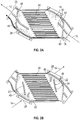
FIG. 2A is a plan view of a first flowpath of an embodiment of a heat exchanger; -
FIG. 2B is a plan view of a second flow path of an embodiment of a heat exchanger; -
FIG. 3 is a partial cross-sectional view of an embodiment of a core section of a heat exchanger; -
FIG. 4 is a plan view of an inlet heating arrangement of a heat exchanger; -
FIG. 5 is a cross-sectional view of an inlet heating arrangement of a heat exchanger; -
FIG. 6 is a cross-sectional view of a fluid passage drain arrangement of a heat exchanger; -
FIG. 7 is another cross-sectional view of a fluid passage drain arrangement of a heat exchanger; -
FIG. 8 is an end view of a fluid passage drain arrangement of a heat exchanger; and -
FIG. 9 is another view of a fluid passage drain arrangement of a heat exchanger. - A detailed description of one or more embodiments of the disclosed apparatus and method are presented herein by way of exemplification and not limitation with reference to the Figures.
- Referring now to
FIG. 1 , illustrated is a schematic view of an embodiment of aheat exchanger 10. Theheat exchanger 10 facilitates an exchange of thermal energy between afirst fluid flow 12 and asecond fluid flow 14 directed through theheat exchanger 10. In some embodiments, thefirst fluid flow 12 is a relatively high temperature, high pressure fluid flow such as a bleed airflow from a compressor of a gas turbine engine. Further, in some embodiments thesecond fluid flow 14 is a relatively low temperature, low pressure fluid flow such as RAM airflow for use by an aircraft environmental control system (not shown). - As shown in
FIG. 1 and inFIG. 2A , theheat exchanger 10 includes a firstfluid flow path 16 along which thefirst fluid flow 12 is directed through theheat exchanger 10 from afirst inlet 18 to afirst outlet 20. Similarly, as shown inFIG. 1 and2B , theheat exchanger 10 includes a secondfluid flow path 22 along which thesecond fluid flow 14 is directed from asecond inlet 24 to asecond outlet 26. Theheat exchanger 10 is acounter-flow heat exchanger 10 such that at acore section 28 of theheat exchanger 10, thefirst fluid flow 12 and thesecond fluid flow 14 are flowing in substantially opposite directions. - A cross-sectional view of a portion of the
core section 28 of theheat exchanger 10 is illustrated inFIG. 3 . Thecore section 28 includes a plurality offirst passages 30 to convey thefirst fluid flow 12 therethrough, and a plurality ofsecond passages 32 to convey thesecond fluid flow 14 therethrough. Thefirst fluid passages 30 are circular in cross-section. This allows thefirst fluid passages 30 to convey the high pressurefirst fluid flow 12, and to allow for the use of lower strength polymeric materials in place of the traditional metal materials in forming thefirst fluid passages 30, thesecond fluid passages 32 and thecore section 28. For some materials the first fluid passages may be any polygonal shape that maximizes primary heat transfer area between the first and the second fluid. Thesecond fluid passages 32 are located between adjacentfirst fluid passages 30 and are separated from thefirst fluid passages 30 byweb sections 34, which at least partially form walls of thefirst fluid passages 30. While in some embodiments, thesecond fluid passages 32 may have a circular cross sections, thesecond fluid passages 32 may have other cross-sectional shapes due to the lower pressure of thesecond fluid flow 14. - Referring again to
FIG. 2A , afirst inlet manifold 36 is located between thefirst inlet 18 and thecore section 28, and a first outlet manifold 38 is located between thecore section 28 and thefirst outlet 20. Thefirst inlet manifold 36 is configured to minimize contraction losses at transition area between thefirst inlet manifold 36 and thefirst fluid passages 30 of thecore section 28. This includes aerodynamic design of the leading edges in the header section, optimized header hydraulic diameter to balance pressure loss and the core, etc. Thefirst inlet manifold 36 includes one or morefirst inlet vanes 40 located between thefirst inlet 18 and thecore section 28 to distribute thefirst fluid flow 12 to the plurality offirst fluid passages 30. While the embodiment ofFIG. 2A shows onefirst inlet vane 40, it is to be appreciated that that other quantities of first inlet vanes 40, such as 2, or 3 or morefirst inlet vanes 40, may be utilized to distribute thefirst fluid flow 12 in a selected way. The quantity and arrangement offirst inlet vanes 40 may depend on, for example, afirst inlet angle 42 between thefirst inlet 18 and thecore section 28. These vanes are also designed to provide structural strength in the header / manifold section of the heat exchangers. Additionally good flow distribution with minimal flow pressure loss can also be attained by optimizing the outer mold line shapes of the inlet and outlet manifolds. Inlet and outlet manifolds could have different designs of the internal vanes and their outer mold line shapes for enhancing flow distribution and reducing pressure loss. - Similarly, the
first outlet manifold 38 includes one or morefirst outlet vanes 44 located between thecore section 28 and thefirst outlet 20 to smoothly direct thefirst fluid flow 12 from thecore section 28 to thefirst outlet 20, minimizing losses. While the embodiment ofFIG. 2A shows onefirst outlet vane 44, it is to be appreciated that that other quantities offirst outlet vanes 44 such as 2, or 3 or morefirst outlet vanes 44, may be utilized to direct thefirst fluid flow 12 in a selected way. The quantity and arrangement offirst outlet vanes 44 may depend on, for example, afirst outlet angle 46 between thefirst outlet 20 and thecore section 28. - Referring again to
FIG. 2B , asecond inlet manifold 46 is located between thesecond inlet 24 and thecore section 28, and asecond outlet manifold 48 is located between thecore section 28 and thesecond outlet 26. Thesecond inlet manifold 46 is configured to minimize contraction losses at transition area between thesecond inlet manifold 46 and the secondfluid passages 32 of thecore section 28. This is achieved by smoothly lofting the flow cross-section from the core channels, e.g., circular tubes, to a rectangular slot in the headers. This transition region is designed such that flow separation and blockage is minimized in the transition region. One way to achieve that is maintaining constant flow cross sectional areas for both flow streams in the transition region. Thesecond inlet manifold 46 includes one or moresecond inlet vanes 50 located between thesecond inlet 24 and thecore section 28 to distribute thesecond fluid flow 14 to the plurality of secondfluid passages 32. While the embodiment ofFIG. 2B shows onesecond inlet vane 50, it is to be appreciated that that other quantities ofsecond inlet vanes 50, such as 2, or 3 or moresecond inlet vanes 50, may be utilized to distribute thesecond fluid flow 14 in a selected way. The quantity and arrangement ofsecond inlet vanes 50 may depend on, for example, asecond inlet angle 52 between thesecond inlet 24 and thecore section 28. - Similarly, the
second outlet manifold 48 includes one or moresecond outlet vanes 54 located between thecore section 28 and thesecond outlet 26 to smoothly direct thesecond fluid flow 14 from thecore section 28 to thesecond outlet 26, minimizing losses. While the embodiment ofFIG. 2B shows onesecond outlet vane 54, it is to be appreciated that that other quantities ofsecond outlet vanes 54 such as 2, or 3 or moresecond outlet vanes 54, may be utilized to direct thesecond fluid flow 14 in a selected way. The quantity and arrangement ofsecond outlet vanes 54 may depend on, for example, a second outlet angle 56 between thesecond outlet 26 and thecore section 28. - While the
vanes heat exchanger 10 smoothly and efficiently, thevanes heat exchanger 10. This further enables the use of polymeric materials such as epoxy resins, polyurethane materials, or the like in formation of theheat exchanger 10. - Referring now to
FIG. 4 and 5 , as stated above, the ingestion of ice and/or snow through thesecond inlet 24 reduces performance of theheat exchanger 10 by, for example, clogging thesecond inlet 24 and/or the secondfluid passages 32. To enable ice-free operation of theheat exchanger 10, theheat exchanger 10 includes a heating apparatus located at thesecond inlet 24. More particularly, theheat exchanger 10 includes one ormore bypass passages 58 extending from thefirst inlet 18 toward thesecond inlet 24. Thebypass passages 58 direct abypass portion 60 of thefirst fluid flow 12 toward thesecond inlet 24, bypassing thecore section 28. As thebypass portion 60 passes thesecond inlet 24, thesecond inlet 24 is heated via conduction. The heatedsecond inlet 24 reduces ice and/or snow ingestion at thesecond inlet 24, thus improving performance of theheat exchanger 10. After passing thesecond inlet 24, thebypass portion 60 is directed through thefirst outlet 20 via thefirst outlet manifold 38. While in the embodiment illustrated, the flow of thebypass portion 60 is constant, in other embodiments the flow of thebypass portion 60 may be modulated via, for example, one or more valves (not shown) operable to open or close directing flow through thebypass passages 58 when, for example, thesecond fluid flow 14 is at a sub-freezing temperature. - Referring now to
FIGs. 6-8 , during operating of theheat exchanger 10 condensation may form on an interior on each of the firstfluid passages 30, due to the high relative humidity of thefirst fluid flow 12. It is desired to remove the condensation from theheat exchanger 10 such that the condensation does not proceed through thefirst outlet 20. As shown inFIG. 6 , the firstfluid passages 30 are provided with scupper drains 62 into which the condensation is urged by flow of thefirst fluid flow 12 through the firstfluid passages 30. In some embodiments, the scupper drains 62 comprise openings or notches in the firstfluid passages 30. - As shown in
FIG. 7 , the scupper drains 62 of the firstfluid passages 30 of eachpassage layer 64 of thecore section 28 are connected by alayer drain 66. Thelayer drain 66 collects the condensation from the scupper drains 62 of thepassage layer 64 and directs the condensation to alayer end 68. As shown inFIG. 8 , acore drain 70 is located at thelayer end 68, to collect the condensation from the layer drains 66 and drain the condensation downwardly along anouter surface 72 out theheat exchanger 10. Thecore drain 70 may be, for example a tubular element extending along theouter surface 72, or alternatively may be a notch or the like in theouter surface 72 of theheat exchanger 10. Thecore drain 70 includes adrain outlet 74 through which the condensation exits theheat exchanger 10. - It is expected that the condensate flowing through the scupper drains 62 will entrain some air flow from the bulk flow. Hence, a water removal and air re-entrainment apparatus is utilized. Once the condensate mixture comes out of the HX core through the core drains 70, it enters a
water removal chamber 76, shown inFIG. 9 . Thewater removal chamber 76 includes multi-passagetortuous flow channels 78 which slow down the air-water mixture such that water/ condensate flows down due to gravity into a water reservoir. This reservoir is ultimately connected to thedrain outlet 74 from which the condensate can freely flow out and may be utilized in other parts of theECS 10. The remaining air is re-entrained back into the HX main flow path throughre-entrainment holes 80 that are located in the HX outlet manifold. Some local features near there-entrainment holes 80 can be added to decrease the local flow static pressure such that the overflow air can be effectively re-entrained into the main flow stream. These features reduce the air leakage associated with water separation duringECS 10 operation. - With this drainage arrangement, a separate water removal system downstream of the
heat exchanger 10 is not necessary, which is a significant savings in component cost and volume. Further, theheat exchanger 10 features disclosed herein may be integrally formed with polymeric materials via molding or additive manufacturing methods. Further, the use of polymeric materials has additional benefits in reduced weight, improved corrosion resistance, low surface energy to assist in ice removal, and reduction in raw material costs, as compared to heat exchangers formed with a traditional metal construction. - The term "about" is intended to include the degree of error associated with measurement of the particular quantity based upon the equipment available at the time of filing the application.
- The terminology used herein is for the purpose of describing particular embodiments only and is not intended to be limiting of the present disclosure. As used herein, the singular forms "a", "an" and "the" are intended to include the plural forms as well, unless the context clearly indicates otherwise. It will be further understood that the terms "comprises" and/or "comprising," when used in this specification, specify the presence of stated features, integers, steps, operations, elements, and/or components, but do not preclude the presence or addition of one or more other features, integers, steps, operations, element components, and/or groups thereof.
- While the present disclosure has been described with reference to an exemplary embodiment or embodiments, it will be understood by those skilled in the art that various changes may be made and equivalents may be substituted for elements thereof without departing from the scope of the present disclosure. In addition, many modifications may be made to adapt a particular situation or material to the teachings of the present disclosure without departing from the essential scope thereof. Therefore, it is intended that the present disclosure not be limited to the particular embodiment disclosed as the best mode contemplated for carrying out this present disclosure, but that the present disclosure will include all embodiments falling within the scope of the claims.
Claims (14)
- A counterflow heat exchanger (10) configured to exchange thermal energy between a first fluid flow (12) at a first pressure and a second fluid flow (14) at a second pressure less than the first pressure, comprising:a first fluid inlet (18);a first fluid outlet (20) fluidly coupled to the first fluid inlet (18) via a core section (28);a second fluid inlet (24);a second fluid outlet (26) fluidly coupled to the second fluid inlet (24) via the core section (28);the core section (28) including:a plurality of first fluid passages (30) configured to convey the first fluid flow (12) from the first fluid inlet (18) toward the first fluid outlet (20); anda plurality of second fluid passages (32) configured to convey the second fluid flow (14) from the second fluid inlet (24) toward the second fluid outlet (26) such that the first fluid flow (12) exchanges thermal energy with the second fluid flow (14) at the core section;one or more drains operably connected to the plurality of first fluid passages (30) configured to remove condensation from an interior of the first fluid passages (30) prior to the condensation reaching the first fluid outlet (20).
- The counterflow heat exchanger (10) of claim 1, wherein the plurality of one or more drains includes one or more scupper drains (62) formed in the first fluid passages (30).
- The counterflow heat exchanger (10) of claim 2, wherein the one or more scupper drains (62) are fluidly connected to a core drain (70), the core drain (70) configured to collect the condensation from the scupper drains (62) and remove the condensation from the heat exchanger.
- The counterflow heat exchanger (10) of claim 2 or 3, wherein the first fluid passages (30) are arranged in one or more layers, the scupper drains (62) fluidly connected to the core drain (70) via one or more layer drains (66).
- The counterflow heat exchanger (10) of claim 2, 3 or 4, wherein the one or more scupper drains (62) are one or more openings in the first fluid passages (30).
- The counterflow heat exchanger (10) of any preceding claim, wherein the plurality of first fluid passages (30) are connected to the plurality of second fluid passages (32) via one or more web portions (34).
- The counterflow heat exchanger (10) of claim 6, wherein the one or more web portions (34) define at least a portion of the passage wall of the plurality of first fluid passages (30).
- The counterflow heat exchanger (10) of any preceding claim, wherein a first flow direction of the first fluid flow (12) through the first fluid inlet (18) is nonparallel to the first flow direction of the first fluid flow (12) through the plurality of first fluid passages (30).
- The counterflow heat exchanger (10) of any preceding claim, wherein a second flow direction of the second fluid flow (14) through the second fluid inlet (24) is nonparallel to the second flow direction of the second fluid flow (14) through the plurality of second fluid passages (32).
- The counterflow heat exchanger (10) of any preceding claim, wherein a first flow direction of the first fluid flow (12) through the plurality of first fluid passages (30) is opposite a second flow direction of the second fluid flow (14) through the plurality of second fluid passages (32).
- The counterflow heat exchanger (10) of any preceding claim, wherein the heat exchanger (10) is formed from a polymeric material.
- The counterflow heat exchanger (10) of any preceding claim, further comprising a water removal and air re-entrainment apparatus disposed between the plurality of second fluid passages (32) and the one or more drains.
- The counterflow heat exchanger (10) of claim 12, wherein the water removal and air re-entrainment apparatus includes a water removal chamber (76) including multi-passage tortuous flow channels (78) to separate condensate from airflow.
- The counterflow heat exchanger (10) of claim 13, wherein the water removal and air re-entrainment apparatus includes one or more air re-entrainment holes (80) in the outlet manifold to re-introduce airflow from the water removal chamber into the outlet manifold.
Applications Claiming Priority (1)
| Application Number | Priority Date | Filing Date | Title |
|---|---|---|---|
| US16/018,782 US11333438B2 (en) | 2018-06-26 | 2018-06-26 | Heat exchanger with water extraction |
Publications (2)
| Publication Number | Publication Date |
|---|---|
| EP3587983A1 true EP3587983A1 (en) | 2020-01-01 |
| EP3587983B1 EP3587983B1 (en) | 2023-08-02 |
Family
ID=67105759
Family Applications (1)
| Application Number | Title | Priority Date | Filing Date |
|---|---|---|---|
| EP19182665.0A Active EP3587983B1 (en) | 2018-06-26 | 2019-06-26 | Heat exchanger with integral features |
Country Status (2)
| Country | Link |
|---|---|
| US (1) | US11333438B2 (en) |
| EP (1) | EP3587983B1 (en) |
Families Citing this family (6)
| Publication number | Priority date | Publication date | Assignee | Title |
|---|---|---|---|---|
| USD965760S1 (en) * | 2020-01-02 | 2022-10-04 | Dynaeon Industrial Co., Ltd. | Cooling fan with two air outlets |
| CN115885147A (en) * | 2020-09-30 | 2023-03-31 | 亿康先达国际集团股份有限公司 | Channel type heat exchanger |
| JP7492468B2 (en) * | 2021-02-10 | 2024-05-29 | 三菱重工業株式会社 | Heat exchange core and heat exchanger |
| FR3132138B1 (en) * | 2022-01-27 | 2023-12-15 | Liebherr Aerospace Toulouse Sas | HEAT EXCHANGER COMPRISING AT LEAST ONE SIDE ENCAPSULATING PLATE, AIR CONDITIONING SYSTEM AND VEHICLE |
| CN116878326A (en) * | 2023-08-07 | 2023-10-13 | 中国航发沈阳发动机研究所 | Inlet and outlet flow guide structure suitable for aeroengine plate-fin heat exchanger |
| CN120667955B (en) * | 2025-08-20 | 2025-11-28 | 浙江师范大学 | Heat exchanger with adjustable outlet water temperature and application thereof |
Citations (7)
| Publication number | Priority date | Publication date | Assignee | Title |
|---|---|---|---|---|
| US4415024A (en) * | 1980-11-05 | 1983-11-15 | Joy Manufacturing Company | Heat exchanger assembly |
| US20140000841A1 (en) * | 2012-06-29 | 2014-01-02 | Robert L. Baker | Compressed gas cooling apparatus |
| US20150276329A1 (en) * | 2014-03-31 | 2015-10-01 | Hitachi, Ltd. | Heat Exchanger and Heat Transfer Tube of the Heat Exchanger |
| WO2016057443A1 (en) * | 2014-10-07 | 2016-04-14 | Unison Industries, Llc | Multi-branch furcating flow heat exchanger |
| EP3124906A1 (en) * | 2015-07-30 | 2017-02-01 | General Electric Company | Counter-flow heat exchanger with helical passages |
| US20170089643A1 (en) * | 2015-09-25 | 2017-03-30 | Westinghouse Electric Company, Llc. | Heat Exchanger |
| US20180045102A1 (en) * | 2016-08-10 | 2018-02-15 | Mahle International Gmbh | Charge air cooler for a motor vehicle |
Family Cites Families (33)
| Publication number | Priority date | Publication date | Assignee | Title |
|---|---|---|---|---|
| US3981466A (en) | 1974-12-23 | 1976-09-21 | The Boeing Company | Integrated thermal anti-icing and environmental control system |
| US4187090A (en) | 1978-09-29 | 1980-02-05 | United Technologies Corporation | Heat exchanger water collection system |
| US4681610A (en) * | 1986-02-13 | 1987-07-21 | United Technologies Corporation | High performance water collector |
| US4862952A (en) | 1988-05-09 | 1989-09-05 | United Technologies Corporation | Frost free heat exchanger |
| US5214935A (en) * | 1990-02-20 | 1993-06-01 | Allied-Signal Inc. | Fluid conditioning apparatus and system |
| IL114613A (en) | 1995-07-16 | 1999-09-22 | Tat Ind Ltd | Parallel flow condenser heat exchanger |
| US6415860B1 (en) | 2000-02-09 | 2002-07-09 | Board Of Supervisors Of Louisiana State University And Agricultural And Mechanical College | Crossflow micro heat exchanger |
| JP2001355994A (en) | 2000-06-12 | 2001-12-26 | Toyo Radiator Co Ltd | Stacked type heat exchanger for cooling gas |
| US6460353B2 (en) | 2001-03-02 | 2002-10-08 | Honeywell International Inc. | Method and apparatus for improved aircraft environmental control system utilizing parallel heat exchanger arrays |
| DE10247335B3 (en) * | 2002-10-10 | 2004-04-08 | Liebherr-Aerospace Lindenberg Gmbh | Aircraft climate control system has a condenser unit with inlet and outlet for the recirculated air, inlet and outlet for the refrigerated air and a heat exchanger with a bypass |
| DE102004036568A1 (en) * | 2004-07-28 | 2006-02-16 | Liebherr-Aerospace Lindenberg Gmbh | Water separator for air conditioners |
| US7757502B2 (en) | 2004-09-22 | 2010-07-20 | Hamilton Sundstrand Corporation | RAM fan system for an aircraft environmental control system |
| US8875535B2 (en) * | 2009-12-02 | 2014-11-04 | Hamilton Sundstrand Corporation | Compact condenser module including a tortuous path for removing water droplets from air |
| US20200182553A9 (en) | 2010-02-12 | 2020-06-11 | Dustin Eplee | Counter-Flow Membrane Plate Exchanger and Method of Making |
| US20130061617A1 (en) | 2011-09-13 | 2013-03-14 | Honeywell International Inc. | Air cycle condenser cold inlet heating using internally finned hot bars |
| US9182175B2 (en) | 2011-12-01 | 2015-11-10 | The Boeing Company | Anti-icing heat exchanger |
| US8707716B1 (en) | 2011-12-14 | 2014-04-29 | The Boeing Company | Re-circulating defrosting heat exchanger |
| DE102012201223A1 (en) | 2012-01-27 | 2013-08-01 | Airbus Operations Gmbh | Heat exchanger for cooling air, heating for one and galley with such a heat exchanger |
| US9200855B2 (en) | 2012-03-06 | 2015-12-01 | Honeywell International Inc. | Tubular heat exchange systems |
| US9527594B2 (en) | 2012-04-24 | 2016-12-27 | Hamilton Sundstrand Corporation | Condenser with recirculation air mixer |
| US9448010B2 (en) | 2012-05-10 | 2016-09-20 | Hamilton Sundstrand Corporation | Heat exchanger |
| US9022319B2 (en) | 2012-12-13 | 2015-05-05 | Hamilton Sundstrand Corporation | Condenser ice removal for environmental control system |
| US9745069B2 (en) | 2013-01-21 | 2017-08-29 | Hamilton Sundstrand Corporation | Air-liquid heat exchanger assembly having a bypass valve |
| US9187180B2 (en) | 2013-05-24 | 2015-11-17 | Hamilton Sundstrand Corporation | Thermal pneumatic deicing system for an aircraft RAM air heat exchanger |
| US20150300745A1 (en) * | 2014-04-16 | 2015-10-22 | Enterex America LLC | Counterflow helical heat exchanger |
| US10024557B2 (en) * | 2015-08-14 | 2018-07-17 | Honeywell International Inc. | Water extractor device using scuppers |
| US20170146305A1 (en) * | 2015-11-24 | 2017-05-25 | Hamilton Sundstrand Corporation | Header for heat exchanger |
| US20170198976A1 (en) | 2016-01-13 | 2017-07-13 | Hamilton Sundstrand Corporation | Heat exchangers |
| US11243030B2 (en) | 2016-01-13 | 2022-02-08 | Hamilton Sundstrand Corporation | Heat exchangers |
| US20170198978A1 (en) | 2016-01-13 | 2017-07-13 | Hamilton Sundstrand Corporation | Heat exchangers |
| US20170198979A1 (en) | 2016-01-13 | 2017-07-13 | Hamilton Sundstrand Corporation | Heat exchangers |
| US10168114B2 (en) | 2016-08-30 | 2019-01-01 | Hamilton Sundstrand Corporation | Integral drain assembly for a heat exchanger and method of forming |
| US10451360B2 (en) | 2016-10-24 | 2019-10-22 | Hamilton Sundstrand Corporation | Heat exchanger with integral anti-icing |
-
2018
- 2018-06-26 US US16/018,782 patent/US11333438B2/en active Active
-
2019
- 2019-06-26 EP EP19182665.0A patent/EP3587983B1/en active Active
Patent Citations (7)
| Publication number | Priority date | Publication date | Assignee | Title |
|---|---|---|---|---|
| US4415024A (en) * | 1980-11-05 | 1983-11-15 | Joy Manufacturing Company | Heat exchanger assembly |
| US20140000841A1 (en) * | 2012-06-29 | 2014-01-02 | Robert L. Baker | Compressed gas cooling apparatus |
| US20150276329A1 (en) * | 2014-03-31 | 2015-10-01 | Hitachi, Ltd. | Heat Exchanger and Heat Transfer Tube of the Heat Exchanger |
| WO2016057443A1 (en) * | 2014-10-07 | 2016-04-14 | Unison Industries, Llc | Multi-branch furcating flow heat exchanger |
| EP3124906A1 (en) * | 2015-07-30 | 2017-02-01 | General Electric Company | Counter-flow heat exchanger with helical passages |
| US20170089643A1 (en) * | 2015-09-25 | 2017-03-30 | Westinghouse Electric Company, Llc. | Heat Exchanger |
| US20180045102A1 (en) * | 2016-08-10 | 2018-02-15 | Mahle International Gmbh | Charge air cooler for a motor vehicle |
Also Published As
| Publication number | Publication date |
|---|---|
| EP3587983B1 (en) | 2023-08-02 |
| US20190390916A1 (en) | 2019-12-26 |
| US11333438B2 (en) | 2022-05-17 |
Similar Documents
| Publication | Publication Date | Title |
|---|---|---|
| EP3587981B1 (en) | Heat exchanger with integral features | |
| EP3587983B1 (en) | Heat exchanger with integral features | |
| EP3587982B1 (en) | Heat exchanger with integral features | |
| DK2722627T3 (en) | Hybrid heat exchanging. | |
| CN101617181B (en) | Dual-circuit chiller with two-pass heat exchanger in a series counterflow arrangement | |
| EP2780650A1 (en) | Shell and tube heat exchanger | |
| EP2054679A1 (en) | Plate heat exchanger and heat exchanger plant | |
| US20200096259A1 (en) | Microtube heat exchanger header | |
| EP2875302B1 (en) | Hybrid condenser | |
| JP3926854B2 (en) | Air-cooled condenser | |
| US7096666B2 (en) | Air-cooled condensing system and method | |
| CN116242194A (en) | Drains for evaporator cores | |
| CA1280741C (en) | Frost free heat exchanger | |
| CZ2000766A3 (en) | Heat-exchange system with closed circuit and process with reduced consumption of water | |
| CS254774B1 (en) | Air-cooled water vapor condenser | |
| MXPA99010878A (en) | Low profile heat exchange system with reduced consumption of a | |
| HK1140252A (en) | Dual-circuit chiller with two-pass heat exchanger in a series counterflow arrangement | |
| PL209476B1 (en) | Spiral counter-flow ventilation heat exchanger |
Legal Events
| Date | Code | Title | Description |
|---|---|---|---|
| PUAI | Public reference made under article 153(3) epc to a published international application that has entered the european phase |
Free format text: ORIGINAL CODE: 0009012 |
|
| STAA | Information on the status of an ep patent application or granted ep patent |
Free format text: STATUS: THE APPLICATION HAS BEEN PUBLISHED |
|
| AK | Designated contracting states |
Kind code of ref document: A1 Designated state(s): AL AT BE BG CH CY CZ DE DK EE ES FI FR GB GR HR HU IE IS IT LI LT LU LV MC MK MT NL NO PL PT RO RS SE SI SK SM TR |
|
| AX | Request for extension of the european patent |
Extension state: BA ME |
|
| STAA | Information on the status of an ep patent application or granted ep patent |
Free format text: STATUS: REQUEST FOR EXAMINATION WAS MADE |
|
| 17P | Request for examination filed |
Effective date: 20200630 |
|
| RBV | Designated contracting states (corrected) |
Designated state(s): AL AT BE BG CH CY CZ DE DK EE ES FI FR GB GR HR HU IE IS IT LI LT LU LV MC MK MT NL NO PL PT RO RS SE SI SK SM TR |
|
| STAA | Information on the status of an ep patent application or granted ep patent |
Free format text: STATUS: EXAMINATION IS IN PROGRESS |
|
| 17Q | First examination report despatched |
Effective date: 20211118 |
|
| GRAP | Despatch of communication of intention to grant a patent |
Free format text: ORIGINAL CODE: EPIDOSNIGR1 |
|
| STAA | Information on the status of an ep patent application or granted ep patent |
Free format text: STATUS: GRANT OF PATENT IS INTENDED |
|
| INTG | Intention to grant announced |
Effective date: 20230222 |
|
| GRAS | Grant fee paid |
Free format text: ORIGINAL CODE: EPIDOSNIGR3 |
|
| GRAA | (expected) grant |
Free format text: ORIGINAL CODE: 0009210 |
|
| STAA | Information on the status of an ep patent application or granted ep patent |
Free format text: STATUS: THE PATENT HAS BEEN GRANTED |
|
| AK | Designated contracting states |
Kind code of ref document: B1 Designated state(s): AL AT BE BG CH CY CZ DE DK EE ES FI FR GB GR HR HU IE IS IT LI LT LU LV MC MK MT NL NO PL PT RO RS SE SI SK SM TR |
|
| REG | Reference to a national code |
Ref country code: GB Ref legal event code: FG4D |
|
| REG | Reference to a national code |
Ref country code: CH Ref legal event code: EP |
|
| REG | Reference to a national code |
Ref country code: DE Ref legal event code: R096 Ref document number: 602019033896 Country of ref document: DE |
|
| REG | Reference to a national code |
Ref country code: IE Ref legal event code: FG4D |
|
| REG | Reference to a national code |
Ref country code: LT Ref legal event code: MG9D |
|
| REG | Reference to a national code |
Ref country code: NL Ref legal event code: MP Effective date: 20230802 |
|
| REG | Reference to a national code |
Ref country code: AT Ref legal event code: MK05 Ref document number: 1595227 Country of ref document: AT Kind code of ref document: T Effective date: 20230802 |
|
| PG25 | Lapsed in a contracting state [announced via postgrant information from national office to epo] |
Ref country code: GR Free format text: LAPSE BECAUSE OF FAILURE TO SUBMIT A TRANSLATION OF THE DESCRIPTION OR TO PAY THE FEE WITHIN THE PRESCRIBED TIME-LIMIT Effective date: 20231103 |
|
| PG25 | Lapsed in a contracting state [announced via postgrant information from national office to epo] |
Ref country code: IS Free format text: LAPSE BECAUSE OF FAILURE TO SUBMIT A TRANSLATION OF THE DESCRIPTION OR TO PAY THE FEE WITHIN THE PRESCRIBED TIME-LIMIT Effective date: 20231202 |
|
| PG25 | Lapsed in a contracting state [announced via postgrant information from national office to epo] |
Ref country code: SE Free format text: LAPSE BECAUSE OF FAILURE TO SUBMIT A TRANSLATION OF THE DESCRIPTION OR TO PAY THE FEE WITHIN THE PRESCRIBED TIME-LIMIT Effective date: 20230802 Ref country code: RS Free format text: LAPSE BECAUSE OF FAILURE TO SUBMIT A TRANSLATION OF THE DESCRIPTION OR TO PAY THE FEE WITHIN THE PRESCRIBED TIME-LIMIT Effective date: 20230802 Ref country code: PT Free format text: LAPSE BECAUSE OF FAILURE TO SUBMIT A TRANSLATION OF THE DESCRIPTION OR TO PAY THE FEE WITHIN THE PRESCRIBED TIME-LIMIT Effective date: 20231204 Ref country code: NO Free format text: LAPSE BECAUSE OF FAILURE TO SUBMIT A TRANSLATION OF THE DESCRIPTION OR TO PAY THE FEE WITHIN THE PRESCRIBED TIME-LIMIT Effective date: 20231102 Ref country code: NL Free format text: LAPSE BECAUSE OF FAILURE TO SUBMIT A TRANSLATION OF THE DESCRIPTION OR TO PAY THE FEE WITHIN THE PRESCRIBED TIME-LIMIT Effective date: 20230802 Ref country code: LV Free format text: LAPSE BECAUSE OF FAILURE TO SUBMIT A TRANSLATION OF THE DESCRIPTION OR TO PAY THE FEE WITHIN THE PRESCRIBED TIME-LIMIT Effective date: 20230802 Ref country code: LT Free format text: LAPSE BECAUSE OF FAILURE TO SUBMIT A TRANSLATION OF THE DESCRIPTION OR TO PAY THE FEE WITHIN THE PRESCRIBED TIME-LIMIT Effective date: 20230802 Ref country code: IS Free format text: LAPSE BECAUSE OF FAILURE TO SUBMIT A TRANSLATION OF THE DESCRIPTION OR TO PAY THE FEE WITHIN THE PRESCRIBED TIME-LIMIT Effective date: 20231202 Ref country code: HR Free format text: LAPSE BECAUSE OF FAILURE TO SUBMIT A TRANSLATION OF THE DESCRIPTION OR TO PAY THE FEE WITHIN THE PRESCRIBED TIME-LIMIT Effective date: 20230802 Ref country code: GR Free format text: LAPSE BECAUSE OF FAILURE TO SUBMIT A TRANSLATION OF THE DESCRIPTION OR TO PAY THE FEE WITHIN THE PRESCRIBED TIME-LIMIT Effective date: 20231103 Ref country code: FI Free format text: LAPSE BECAUSE OF FAILURE TO SUBMIT A TRANSLATION OF THE DESCRIPTION OR TO PAY THE FEE WITHIN THE PRESCRIBED TIME-LIMIT Effective date: 20230802 Ref country code: AT Free format text: LAPSE BECAUSE OF FAILURE TO SUBMIT A TRANSLATION OF THE DESCRIPTION OR TO PAY THE FEE WITHIN THE PRESCRIBED TIME-LIMIT Effective date: 20230802 |
|
| PG25 | Lapsed in a contracting state [announced via postgrant information from national office to epo] |
Ref country code: PL Free format text: LAPSE BECAUSE OF FAILURE TO SUBMIT A TRANSLATION OF THE DESCRIPTION OR TO PAY THE FEE WITHIN THE PRESCRIBED TIME-LIMIT Effective date: 20230802 |
|
| PG25 | Lapsed in a contracting state [announced via postgrant information from national office to epo] |
Ref country code: ES Free format text: LAPSE BECAUSE OF FAILURE TO SUBMIT A TRANSLATION OF THE DESCRIPTION OR TO PAY THE FEE WITHIN THE PRESCRIBED TIME-LIMIT Effective date: 20230802 |
|
| PG25 | Lapsed in a contracting state [announced via postgrant information from national office to epo] |
Ref country code: SM Free format text: LAPSE BECAUSE OF FAILURE TO SUBMIT A TRANSLATION OF THE DESCRIPTION OR TO PAY THE FEE WITHIN THE PRESCRIBED TIME-LIMIT Effective date: 20230802 Ref country code: RO Free format text: LAPSE BECAUSE OF FAILURE TO SUBMIT A TRANSLATION OF THE DESCRIPTION OR TO PAY THE FEE WITHIN THE PRESCRIBED TIME-LIMIT Effective date: 20230802 Ref country code: ES Free format text: LAPSE BECAUSE OF FAILURE TO SUBMIT A TRANSLATION OF THE DESCRIPTION OR TO PAY THE FEE WITHIN THE PRESCRIBED TIME-LIMIT Effective date: 20230802 Ref country code: EE Free format text: LAPSE BECAUSE OF FAILURE TO SUBMIT A TRANSLATION OF THE DESCRIPTION OR TO PAY THE FEE WITHIN THE PRESCRIBED TIME-LIMIT Effective date: 20230802 Ref country code: DK Free format text: LAPSE BECAUSE OF FAILURE TO SUBMIT A TRANSLATION OF THE DESCRIPTION OR TO PAY THE FEE WITHIN THE PRESCRIBED TIME-LIMIT Effective date: 20230802 Ref country code: CZ Free format text: LAPSE BECAUSE OF FAILURE TO SUBMIT A TRANSLATION OF THE DESCRIPTION OR TO PAY THE FEE WITHIN THE PRESCRIBED TIME-LIMIT Effective date: 20230802 Ref country code: SK Free format text: LAPSE BECAUSE OF FAILURE TO SUBMIT A TRANSLATION OF THE DESCRIPTION OR TO PAY THE FEE WITHIN THE PRESCRIBED TIME-LIMIT Effective date: 20230802 |
|
| REG | Reference to a national code |
Ref country code: DE Ref legal event code: R097 Ref document number: 602019033896 Country of ref document: DE |
|
| PG25 | Lapsed in a contracting state [announced via postgrant information from national office to epo] |
Ref country code: IT Free format text: LAPSE BECAUSE OF FAILURE TO SUBMIT A TRANSLATION OF THE DESCRIPTION OR TO PAY THE FEE WITHIN THE PRESCRIBED TIME-LIMIT Effective date: 20230802 |
|
| PLBE | No opposition filed within time limit |
Free format text: ORIGINAL CODE: 0009261 |
|
| STAA | Information on the status of an ep patent application or granted ep patent |
Free format text: STATUS: NO OPPOSITION FILED WITHIN TIME LIMIT |
|
| 26N | No opposition filed |
Effective date: 20240503 |
|
| PG25 | Lapsed in a contracting state [announced via postgrant information from national office to epo] |
Ref country code: SI Free format text: LAPSE BECAUSE OF FAILURE TO SUBMIT A TRANSLATION OF THE DESCRIPTION OR TO PAY THE FEE WITHIN THE PRESCRIBED TIME-LIMIT Effective date: 20230802 |
|
| PG25 | Lapsed in a contracting state [announced via postgrant information from national office to epo] |
Ref country code: BG Free format text: LAPSE BECAUSE OF FAILURE TO SUBMIT A TRANSLATION OF THE DESCRIPTION OR TO PAY THE FEE WITHIN THE PRESCRIBED TIME-LIMIT Effective date: 20230802 |
|
| PG25 | Lapsed in a contracting state [announced via postgrant information from national office to epo] |
Ref country code: BG Free format text: LAPSE BECAUSE OF FAILURE TO SUBMIT A TRANSLATION OF THE DESCRIPTION OR TO PAY THE FEE WITHIN THE PRESCRIBED TIME-LIMIT Effective date: 20230802 |
|
| PG25 | Lapsed in a contracting state [announced via postgrant information from national office to epo] |
Ref country code: MC Free format text: LAPSE BECAUSE OF FAILURE TO SUBMIT A TRANSLATION OF THE DESCRIPTION OR TO PAY THE FEE WITHIN THE PRESCRIBED TIME-LIMIT Effective date: 20230802 |
|
| REG | Reference to a national code |
Ref country code: CH Ref legal event code: PL |
|
| PG25 | Lapsed in a contracting state [announced via postgrant information from national office to epo] |
Ref country code: LU Free format text: LAPSE BECAUSE OF NON-PAYMENT OF DUE FEES Effective date: 20240626 |
|
| PG25 | Lapsed in a contracting state [announced via postgrant information from national office to epo] |
Ref country code: IE Free format text: LAPSE BECAUSE OF NON-PAYMENT OF DUE FEES Effective date: 20240626 |
|
| PG25 | Lapsed in a contracting state [announced via postgrant information from national office to epo] |
Ref country code: CH Free format text: LAPSE BECAUSE OF NON-PAYMENT OF DUE FEES Effective date: 20240630 Ref country code: BE Free format text: LAPSE BECAUSE OF NON-PAYMENT OF DUE FEES Effective date: 20240630 |
|
| REG | Reference to a national code |
Ref country code: BE Ref legal event code: MM Effective date: 20240630 |
|
| PGFP | Annual fee paid to national office [announced via postgrant information from national office to epo] |
Ref country code: DE Payment date: 20250520 Year of fee payment: 7 |
|
| PGFP | Annual fee paid to national office [announced via postgrant information from national office to epo] |
Ref country code: GB Payment date: 20250520 Year of fee payment: 7 |
|
| PGFP | Annual fee paid to national office [announced via postgrant information from national office to epo] |
Ref country code: FR Payment date: 20250520 Year of fee payment: 7 |
|
| PG25 | Lapsed in a contracting state [announced via postgrant information from national office to epo] |
Ref country code: CY Free format text: LAPSE BECAUSE OF FAILURE TO SUBMIT A TRANSLATION OF THE DESCRIPTION OR TO PAY THE FEE WITHIN THE PRESCRIBED TIME-LIMIT; INVALID AB INITIO Effective date: 20190626 |
|
| P01 | Opt-out of the competence of the unified patent court (upc) registered |
Free format text: CASE NUMBER: UPC_APP_0018002_3587983/2025 Effective date: 20251217 |
|
| PG25 | Lapsed in a contracting state [announced via postgrant information from national office to epo] |
Ref country code: HU Free format text: LAPSE BECAUSE OF FAILURE TO SUBMIT A TRANSLATION OF THE DESCRIPTION OR TO PAY THE FEE WITHIN THE PRESCRIBED TIME-LIMIT; INVALID AB INITIO Effective date: 20190626 |