EP3587927A1 - Heat shield panel manufacturing process - Google Patents
Heat shield panel manufacturing process Download PDFInfo
- Publication number
- EP3587927A1 EP3587927A1 EP19183457.1A EP19183457A EP3587927A1 EP 3587927 A1 EP3587927 A1 EP 3587927A1 EP 19183457 A EP19183457 A EP 19183457A EP 3587927 A1 EP3587927 A1 EP 3587927A1
- Authority
- EP
- European Patent Office
- Prior art keywords
- sheets
- heat shield
- shield panel
- negative template
- sheet
- Prior art date
- Legal status (The legal status is an assumption and is not a legal conclusion. Google has not performed a legal analysis and makes no representation as to the accuracy of the status listed.)
- Granted
Links
Images




Classifications
-
- F—MECHANICAL ENGINEERING; LIGHTING; HEATING; WEAPONS; BLASTING
- F23—COMBUSTION APPARATUS; COMBUSTION PROCESSES
- F23R—GENERATING COMBUSTION PRODUCTS OF HIGH PRESSURE OR HIGH VELOCITY, e.g. GAS-TURBINE COMBUSTION CHAMBERS
- F23R3/00—Continuous combustion chambers using liquid or gaseous fuel
- F23R3/02—Continuous combustion chambers using liquid or gaseous fuel characterised by the air-flow or gas-flow configuration
- F23R3/04—Air inlet arrangements
-
- B—PERFORMING OPERATIONS; TRANSPORTING
- B32—LAYERED PRODUCTS
- B32B—LAYERED PRODUCTS, i.e. PRODUCTS BUILT-UP OF STRATA OF FLAT OR NON-FLAT, e.g. CELLULAR OR HONEYCOMB, FORM
- B32B15/00—Layered products comprising a layer of metal
- B32B15/01—Layered products comprising a layer of metal all layers being exclusively metallic
-
- B—PERFORMING OPERATIONS; TRANSPORTING
- B32—LAYERED PRODUCTS
- B32B—LAYERED PRODUCTS, i.e. PRODUCTS BUILT-UP OF STRATA OF FLAT OR NON-FLAT, e.g. CELLULAR OR HONEYCOMB, FORM
- B32B3/00—Layered products comprising a layer with external or internal discontinuities or unevennesses, or a layer of non-planar shape; Layered products comprising a layer having particular features of form
- B32B3/26—Layered products comprising a layer with external or internal discontinuities or unevennesses, or a layer of non-planar shape; Layered products comprising a layer having particular features of form characterised by a particular shape of the outline of the cross-section of a continuous layer; characterised by a layer with cavities or internal voids ; characterised by an apertured layer
- B32B3/266—Layered products comprising a layer with external or internal discontinuities or unevennesses, or a layer of non-planar shape; Layered products comprising a layer having particular features of form characterised by a particular shape of the outline of the cross-section of a continuous layer; characterised by a layer with cavities or internal voids ; characterised by an apertured layer characterised by an apertured layer, the apertures going through the whole thickness of the layer, e.g. expanded metal, perforated layer, slit layer regular cells B32B3/12
-
- B—PERFORMING OPERATIONS; TRANSPORTING
- B32—LAYERED PRODUCTS
- B32B—LAYERED PRODUCTS, i.e. PRODUCTS BUILT-UP OF STRATA OF FLAT OR NON-FLAT, e.g. CELLULAR OR HONEYCOMB, FORM
- B32B37/00—Methods or apparatus for laminating, e.g. by curing or by ultrasonic bonding
- B32B37/14—Methods or apparatus for laminating, e.g. by curing or by ultrasonic bonding characterised by the properties of the layers
- B32B37/16—Methods or apparatus for laminating, e.g. by curing or by ultrasonic bonding characterised by the properties of the layers with all layers existing as coherent layers before laminating
- B32B37/18—Methods or apparatus for laminating, e.g. by curing or by ultrasonic bonding characterised by the properties of the layers with all layers existing as coherent layers before laminating involving the assembly of discrete sheets or panels only
-
- B—PERFORMING OPERATIONS; TRANSPORTING
- B32—LAYERED PRODUCTS
- B32B—LAYERED PRODUCTS, i.e. PRODUCTS BUILT-UP OF STRATA OF FLAT OR NON-FLAT, e.g. CELLULAR OR HONEYCOMB, FORM
- B32B38/00—Ancillary operations in connection with laminating processes
- B32B38/10—Removing layers, or parts of layers, mechanically or chemically
-
- F—MECHANICAL ENGINEERING; LIGHTING; HEATING; WEAPONS; BLASTING
- F23—COMBUSTION APPARATUS; COMBUSTION PROCESSES
- F23R—GENERATING COMBUSTION PRODUCTS OF HIGH PRESSURE OR HIGH VELOCITY, e.g. GAS-TURBINE COMBUSTION CHAMBERS
- F23R3/00—Continuous combustion chambers using liquid or gaseous fuel
- F23R3/002—Wall structures
-
- B—PERFORMING OPERATIONS; TRANSPORTING
- B32—LAYERED PRODUCTS
- B32B—LAYERED PRODUCTS, i.e. PRODUCTS BUILT-UP OF STRATA OF FLAT OR NON-FLAT, e.g. CELLULAR OR HONEYCOMB, FORM
- B32B2307/00—Properties of the layers or laminate
- B32B2307/30—Properties of the layers or laminate having particular thermal properties
-
- F—MECHANICAL ENGINEERING; LIGHTING; HEATING; WEAPONS; BLASTING
- F23—COMBUSTION APPARATUS; COMBUSTION PROCESSES
- F23R—GENERATING COMBUSTION PRODUCTS OF HIGH PRESSURE OR HIGH VELOCITY, e.g. GAS-TURBINE COMBUSTION CHAMBERS
- F23R2900/00—Special features of, or arrangements for continuous combustion chambers; Combustion processes therefor
- F23R2900/00018—Manufacturing combustion chamber liners or subparts
-
- F—MECHANICAL ENGINEERING; LIGHTING; HEATING; WEAPONS; BLASTING
- F23—COMBUSTION APPARATUS; COMBUSTION PROCESSES
- F23R—GENERATING COMBUSTION PRODUCTS OF HIGH PRESSURE OR HIGH VELOCITY, e.g. GAS-TURBINE COMBUSTION CHAMBERS
- F23R2900/00—Special features of, or arrangements for continuous combustion chambers; Combustion processes therefor
- F23R2900/03043—Convection cooled combustion chamber walls with means for guiding the cooling air flow
-
- F—MECHANICAL ENGINEERING; LIGHTING; HEATING; WEAPONS; BLASTING
- F23—COMBUSTION APPARATUS; COMBUSTION PROCESSES
- F23R—GENERATING COMBUSTION PRODUCTS OF HIGH PRESSURE OR HIGH VELOCITY, e.g. GAS-TURBINE COMBUSTION CHAMBERS
- F23R2900/00—Special features of, or arrangements for continuous combustion chambers; Combustion processes therefor
- F23R2900/03044—Impingement cooled combustion chamber walls or subassemblies
Definitions
- the subject matter disclosed herein generally relates to gas turbine engines and, more particularly, to a method for manufacturing heat shield panels of gas turbine engines.
- a combustor of a gas turbine engine may be configured and required to burn fuel in a minimum volume. Such configurations may place substantial heat load on the structure of the combustor (e.g., panels, shell, etc.). Such heat loads may dictate that special consideration is given to structures which may be configured as heat shield panels configured to protect the walls of the combustor. Even with such configurations, excess temperatures at various locations may occur leading to oxidation, cracking, and high thermal stresses of the heat shields or panels. Manufacturing of heat shield panels is a difficult process and improvements to the manufacturing process are greatly desired.
- a method of manufacturing a heat shield panel for a gas turbine engine includes: determining a plurality of layers to compose a heat shield panel having one or more cooling apertures with complex geometries; forming each of the plurality of layers into sheets; forming each of the sheets into a three-dimensional slice of the heat shield panel; stacking each of the sheets to form a three-dimensional heat shield panel; and joining the sheets together.
- further embodiments may include that the complex geometries comprise at least one of a spiral passageway, a zig-zag passageway, a branching passageway, a passageway with two or more turns, and a passageway with a curvilinear side wall.
- each sheet is composed of patterned foil.
- further embodiments may include that forming further includes at least one of chemically etching each of the sheets, photochemically etching each of the sheets, stamping each of the sheets, laser cutting each of the sheets, water jet cutting each of the sheets, and wire or plunge electrical discharge machining each of the sheets.
- further embodiments may include that forming further includes chemically etching each of the sheets.
- further embodiments may include that features of each layer are etched into the sheets.
- further embodiments may include that the features include at least one of one of cooling apertures, quench holes, and an attachment mechanism.
- attachment mechanism is a threaded stud.
- each sheet is curved individually.
- further embodiments may include that the sheets are stacked onto a negative template of the heat shield panel.
- further embodiments may include that the negative template of the heat shield panel is configured to curve each of the sheets into a three-dimensional slice of the heat shield panel.
- further embodiments may include that the negative template of the heat shield panel is configured to align each of the sheets.
- further embodiments may include that the negative template includes studs and the negative template of the heat shield panel is configured to align each of the sheets by stacking the sheets onto the negative template such that the studs are inserted through the quench holes.
- further embodiments may include that the negative template includes studs and the negative template of the heat shield panel is configured to align each of the sheets by stacking the sheets onto the negative template such that the studs are inserted through guide holes in one or more removable portions of the sheet proximate outer edges of the sheet.
- further embodiments may include: removing the removable portions from the sheets after they have been joined together.
- joining the sheets together further includes at least one of diffusion bonding the sheets together, cold welding the sheets together, ultrasonic metal welding the sheets together, and other solid state welding method the sheets together.
- joining the sheets together further includes diffusion bonding the sheets together.
- a heat shield panel for a gas turbine engine manufactured by the method of claim 1 includes: a first surface; a second surface opposite the first surface; and a plurality of cooling apertures extending from the first surface to the second surface through the heat shield panel, each of the plurality of cooling apertures are oriented at a non-normal angle relative to the second surface.
- further embodiments may include one or more threaded studs extending away from the second surface of the heat shield panel.
- further embodiments may include one or more quench holes extending from the first surface to the second surface through the heat shield panel.
- Impingement and convective cooling of heat shield panels of the combustor wall may be used to help cool the combustor.
- Convective cooling may be achieved by air that is channeled between the heat shield panels and a combustion liner of the combustor.
- Impingement cooling may be a process of directing relatively cool air from a location exterior to the combustor toward a back or underside of the heat shield panels.
- combustion liners and heat shield panels are utilized to face the extreme temperatures produced by the burning of fuel within a combustion chamber and protect the overall combustor shell.
- the combustion liners may be supplied with cooling air including dilution passages which deliver a high volume of cooling air into a hot flow path.
- the cooling air may be air from the compressor of the gas turbine engine.
- the cooling air may impinge upon a back side of a heat shield panel that faces a combustion liner inside the combustor.
- Heat shield panels often include cooling apertures configured to transfer air from the cooling channel into a combustion area within the combustion chamber.
- the performance of the cooling apertures may be enhanced through utilizing complex geometries, however complex geometries may lead to difficulties during conventional methods of manufacturing the heat shield panels, such as, for example investment casting.
- Embodiments disclosed herein seek to provide a method for manufacturing complex geometries of the heat shield panel.
- FIG. 1 schematically illustrates a gas turbine engine 20.
- the gas turbine engine 20 is disclosed herein as a two-spool turbofan that generally incorporates a fan section 22, a compressor section 24, a combustor section 26 and a turbine section 28.
- Alternative engines might include an augmentor section (not shown) among other systems or features.
- the fan section 22 drives air along a bypass flow path B in a bypass duct, while the compressor section 24 drives air along a core flow path C for compression and communication into the combustor section 26 then expansion through the turbine section 28.
- the exemplary engine 20 generally includes a low speed spool 30 and a high speed spool 32 mounted for rotation about an engine central longitudinal axis A relative to an engine static structure 36 via several bearing systems 38. It should be understood that various bearing systems 38 at various locations may alternatively or additionally be provided, and the location of bearing systems 38 may be varied as appropriate to the application.
- the low speed spool 30 generally includes an inner shaft 40 that interconnects a fan 42, a low pressure compressor 44 and a low pressure turbine 46.
- the inner shaft 40 is connected to the fan 42 through a speed change mechanism, which in exemplary gas turbine engine 20 is illustrated as a geared architecture 48 to drive the fan 42 at a lower speed than the low speed spool 30.
- the high speed spool 32 includes an outer shaft 50 that interconnects a high pressure compressor 52 and high pressure turbine 54.
- a combustor 300 is arranged in exemplary gas turbine 20 between the high pressure compressor 52 and the high pressure turbine 54.
- An engine static structure 36 is arranged generally between the high pressure turbine 54 and the low pressure turbine 46.
- the engine static structure 36 further supports bearing systems 38 in the turbine section 28.
- the inner shaft 40 and the outer shaft 50 are concentric and rotate via bearing systems 38 about the engine central longitudinal axis A which is collinear with their longitudinal axes.
- each of the positions of the fan section 22, compressor section 24, combustor section 26, turbine section 28, and fan drive gear system 48 may be varied.
- gear system 48 may be located aft of combustor section 26 or even aft of turbine section 28, and fan section 22 may be positioned forward or aft of the location of gear system 48.
- the engine 20 in one example is a high-bypass geared aircraft engine.
- the engine 20 bypass ratio is greater than about six (6), with an example embodiment being greater than about ten (10)
- the geared architecture 48 is an epicyclic gear train, such as a planetary gear system or other gear system, with a gear reduction ratio of greater than about 2.3 and the low pressure turbine 46 has a pressure ratio that is greater than about five.
- the engine 20 bypass ratio is greater than about ten (10:1)
- the fan diameter is significantly larger than that of the low pressure compressor 44
- the low pressure turbine 46 has a pressure ratio that is greater than about five (5:1).
- Low pressure turbine 46 pressure ratio is pressure measured prior to inlet of low pressure turbine 46 as related to the pressure at the outlet of the low pressure turbine 46 prior to an exhaust nozzle.
- the geared architecture 48 may be an epicyclic gear train, such as a planetary gear system or other gear system, with a gear reduction ratio of greater than about 2.3:1. It should be understood, however, that the above parameters are only exemplary of one embodiment of a geared architecture engine and that the present disclosure is applicable to other gas turbine engines including direct drive turbofans.
- the fan section 22 of the engine 20 is designed for a particular flight condition--typically cruise at about 0.8 Mach and about 35,000 feet (10,668 meters).
- 'TSFC' Thrust Specific Fuel Consumption
- Low fan pressure ratio is the pressure ratio across the fan blade alone, without a Fan Exit Guide Vane (“FEGV”) system.
- the low fan pressure ratio as disclosed herein according to one non-limiting embodiment is less than about 1.45.
- Low corrected fan tip speed is the actual fan tip speed in ft/sec divided by an industry standard temperature correction of [(Tram °R)/(518.7 °R)] 0.5 .
- the "Low corrected fan tip speed” as disclosed herein according to one non-limiting embodiment is less than about 1150 ft/second (350.5 m/sec).
- a combustor 300 defines a combustion chamber 302.
- the combustion chamber 302 includes a combustion area 370 within the combustion chamber 302.
- the combustor 300 includes an inlet 306 and an outlet 308 through which air may pass.
- the air may be supplied to the combustor 300 by a pre-diffuser 110.
- Air may also enter the combustion chamber 302 through other holes in the combustor 300 including, but not limited to, quench holes 310, as seen in FIG. 2 .
- Compressor air is supplied from the compressor section 24 into a pre-diffuser strut.
- the pre-diffuser strut is configured to direct the airflow into the pre-diffuser 110, which then directs the airflow toward the combustor 300.
- the combustor 300 and the pre-diffuser 110 are separated by a shroud chamber 113 that contains the combustor 300 and includes an inner diameter branch 114 and an outer diameter branch 116. As air enters the shroud chamber 113, a portion of the air may flow into the combustor inlet 306, a portion may flow into the inner diameter branch 114, and a portion may flow into the outer diameter branch 116.
- the air from the inner diameter branch 114 and the outer diameter branch 116 may then enter the combustion chamber 302 by means of one or more impingement holes 307 in the combustion liner 600 and one or more cooling apertures 309 in the heat shield panels 400.
- the impingement holes 307 and cooling apertures 309 may include nozzles, holes, etc.
- the air may then exit the combustion chamber 302 through the combustor outlet 308.
- fuel may be supplied into the combustion chamber 302 from a fuel injector 320 and a pilot nozzle 322, which may be ignited within the combustion chamber 302.
- the combustor 300 of the engine combustion section 26 may be housed within a shroud case 124 which may define the shroud chamber 113.
- the combustor 300 includes multiple heat shield panels 400 that are attached to the combustion liner 600 (See FIG. 3 ).
- the heat shield panels 400 may be arranged parallel to the combustion liner 600.
- the combustion liner 600 can define circular or annular structures with the heat shield panels 400 being mounted on a radially inward liner and a radially outward liner, as will be appreciated by those of skill in the art.
- the heat shield panels 400 can be removably mounted to the combustion liner 600 by one or more attachment mechanisms 332.
- the attachment mechanism 332 may be integrally formed with a respective heat shield panel 400, although other configurations are possible.
- the attachment mechanism 332 may be a threaded stud or other structure that may extend from the respective heat shield panel 400 through the interior surface to a receiving portion or aperture of the combustion liner 600 such that the heat shield panel 400 may be attached to the combustion liner 600 and held in place.
- the heat shield panels 400 partially enclose a combustion area 370 within the combustion chamber 302 of the combustor 300.
- FIG. 3 illustrates a heat shield panel 400 and combustion liner 600 of a combustor 300 (see FIG. 1 ) of a gas turbine engine 20 (see FIG. 1 ).
- the heat shield panel 400 and the combustion liner 600 are in a facing spaced relationship.
- the heat shield panel 400 includes a first surface 410 oriented towards the combustion area 370 of the combustion chamber 302 and a second surface 420 opposite the first surface 410 oriented towards the combustion liner 600.
- the combustion liner 600 has an inner surface 610 and an outer surface 620 opposite the inner surface 610.
- the inner surface 610 is oriented toward the heat shield panel 400.
- the outer surface 620 is oriented outward from the combustor 300 proximate the inner diameter branch 114 and the outer diameter branch 116.
- the combustion liner 600 includes a plurality of impingement holes 307 configured to allow airflow 590 from the inner diameter branch 114 and the outer diameter branch 116 to enter an impingement cavity 390 in between the combustion liner 600 and the heat shield panel 400.
- Each of the impingement holes 307 extend from the outer surface 620 to the inner surface 610 through the combustion liner 600.
- Each of the impingement holes 307 fluidly connects the impingement cavity 390 to at least one of the inner diameter branch 114 and the outer diameter branch 116.
- the heat shield panel 400 may include one or more cooling apertures 309 configured to allow airflow 590 from the impingement cavity 390 to the combustion area 370 of the combustion chamber 302.
- Each of the cooling apertures 309 extend from the second surface 420 to the first surface 410 through the heat shield panel 400. Airflow 590 flowing into the impingement cavity 390 impinges on the second surface 420 of the heat shield panel 400 and absorbs heat from the heat shield panel 400 as it impinges on the second surface 420.
- the heat shield panel 400 contains complex features that may need to be formed during the manufacturing process of the heat shield panel 400.
- the complex features may include the attachment mechanisms 332 extending away from the second surface 420 of the heat shield panel 400. As shown in FIG. 4 , the attachment features 332 may be threaded studs.
- the complex features may also include the quench holes 310, which may be circular in shape, as shown in FIG. 4 . The quench holes 310 may be oriented about perpendicular to the second surface 420 of the heat shield panel 400.
- the complex features may further include the cooling apertures 309, which also may be circular in shape, as shown in FIG. 4 . The cooling apertures 309, may be oriented non-perpendicular to the second surface 420 of the heat shield panel 400.
- the heat shield panel 400 is typically manufactured using an investment casting process. To cast the heat shield panels 400 by investment casting, wax needs to be injected into a tool to create wax patterns that will be used to create a ceramic casting mold, which will then be used to cast the metal heat shield panels 400. Having heat shield panels 400 designs with the attachment features 332 that have integral cast threads about parallel (i.e., normal to the stud of the attachment feature 332) to the second surface 420 of the heat shield panel 400 complicates the investment casting process since the threads of the attachment feature 332 cannot be injected directly with the heat shield panels 400 since the angle of the studs and the threads of the attachment features 332 will back lock in the die, which makes it difficult to remove the wax pattern from the injection die.
- the threads of the attachment features 332 need to be injected separately in wax and then wax welded to the wax pattern.
- Casting the heat shield panel 400 and threads of the attachment features 332 separately leads to casting difficulty and quality issues with thread alignment, thread integrity (free from defects like porosity or stray grains), and thread dimensional conformance. This leads to higher process and component cost.
- the cooling apertures 309 may be oriented at a non-normal angle to the second surface 420 of the heat shield panel 400 or have complex geometries, which make manufacturing the cooling apertures 309 difficult through an investment casting process and other conventional methods.
- the cooling apertures 309 may be conventionally formed by various manufacturing methods including but not limited to laser-drilling and electrical discharge machining (EDM) after the heat shield panel 400 has gone through the investment casting process. These methods may be time-intensive and may only create a few cooling apertures 309 at a time.
- Conventional manufacturing processes e.g., investment casting process
- the simple linear holes may have straight linear side walls and at most one turn 311, as shown by 309b in FIG. 3 .
- the cooling apertures 309 at 309b may be produced by drilling two linear holes include one from the first surface 410 and one from second surface 420. Cooling apertures 309 with complex geometries may be formed using method 700 discussed below.
- Complex geometries may include two or more turns 311, as shown at 309c and 309d in FIG. 3 .
- Complex geometries may include curvilinear side walls 312, as shown at 309c and 309e in FIG. 3 .
- the curvilinear side walls 312 may be designed to accelerate or decelerate the airflow 590 through the cooling apertures 309.
- Complex geometries may include complex shaped airflow passageways 316 to maximize the surface areas for heat flow between the airflow 590 and the heat shield panel 400.
- Complex shape airflow passageways 316 may include but are not limited to spiral passageways 316 shown at 309c in FIG. 3 and zig-zag passageways 316 shown at 309d in FIG. 3 .
- Complex shaped airflow passageways 316 may include also include branching passageways 316 that branch out in to two or more passageways 316, as shown at 309f in FIG. 3 .
- complex shape airflow passageways 316 in Figure 3a may include also include branching passageways 316 that branch out in to two or more passageways 316, as shown in 309g.
- the branching passageways 316 may branch out into passageways 316 about parallel to the first surface 410 and/or the second surface 420.
- the branching passageways 316 may branch out into passageways 316 about parallel to the first surface 410 and/or the second surface 420 on one or more different planes within the heat shield panel 400, as shown at 309g.
- the passages 316 may interconnect at the inlet 309-1 and/or outlets 309-2 as shown at 309h, interconnect at other points 309-3 as shown at 309i, or not interconnect as shown at 309j.
- the branching passageways 316 may also fluidly connect two or more different cooling apertures 309.
- the method 700 described below allows for fabrication of much more complex cooling apertures 309 than conventional methods, which allows for increase surface area of the cooling apertures resulting in greater overall cooling efficiency for the heat shield panel.
- Embodiments disclosed herein seek to address the challenges of manufacturing a heat shield panel 400 using the Tomo Lithographic Molding (TLM) process developed by Mikro Systems, Inc. of Charlottesville, VA as described in patent US 9,879,861 B2 , which is incorporated herein by reference in its entirety.
- TLM Tomo Lithographic Molding
- the TLM process builds up the heat shield panel 400 in layers without the use of castings or cores to produce molds.
- the heat shield panel 400 is created with the complex features described above during the TLM process without the post processing required by investment casting.
- FIG. 5-8 illustrates a method 700 of manufacturing the heat shield panel 400.
- a plurality of layers 850 to compose a heat shield panel 400 are determined, which may include segmenting a model of the heat shield panel into a plurality of layers.
- Block 704 may further include digitally slicing a computer-aided design (CAD) model of the heat shield panel 400 into layers 850.
- CAD computer-aided design
- Each layer 850 represents a three-dimensional slice of the heat shield panel 400 such that when assembled (e.g., laid on top of each other and curved) the layers 850 combine to form the heat shield panel 400.
- Each layer 850 may be the same thickness or the layers 850 may vary in thickness.
- the layers 850 are formed by in each of the sheets 860.
- the sheets 860 may be composed of patterned nickel super-alloy foil.
- the features may be formed in the foil 860 by any standard available means of machining or patterning metal foils including at least one of chemically etching each sheet 860, photochemically etching each sheet 860, stamping each sheet 860, laser cutting each sheet 860, water jet cutting each sheet 860, and wire or plunge electrical discharge machining each sheet 860.
- the features may be formed in the foil 860 by etching features of the layer 850 into a sheet 860.
- the features of each sheet 860 may be different.
- Features may include at least one of cooling apertures 309, quench holes 310, and attachment mechanisms 332.
- one sheet 860 may contain features such as the cooling apertures 309, whereas another sheet 860 may contain features such as quench holes 310, whereas another sheet 860 may contain features such as the attachment mechanisms 332.
- the sheets 860 may each include one or more removable portions 852 proximate the outer edges 854 of the sheet 860. Each of the removable portions 854 may include guide holes 856 that aid in the alignment of the sheets 860 later in the method 700, as discussed below.
- each sheet 860 is formed as a three-dimensional slice of the heat shield panel 400.
- the forming may include flatting and/or curving each sheet 860 as appropriate for the heat shield panel 400.
- some heat shield panels 400 may be flat, some heat shield panels 400 may be curved, and some heat shield panels 400 may be both flat and curved in different areas of the heat shield panels 400.
- Each sheet 860 may be curved individually or the sheets 860 may be curved in unison when stacking at block 710.
- the sheets 860 of etched pattern foil 860 are stacked.
- the sheets 860 may be stacked onto a negative template 900 of the heat shield panel 400.
- the negative template 900 of the heat shield panel 400 is configured to curve each of the sheets 860 into a three-dimensional slice of the heat shield panel 400 in block 708, thus block 708 may be performed simultaneously to block 710 or after block 710.
- the negative template 900 may also be configured to align the sheets 860.
- the negative templates 900 may include one or more studs 910 configured to align the sheets 850.
- the negative template 900 of the heat shield panel 400 is configured to align each of the sheets 860 by stacking the sheets onto the negative template 900 such that the studs 910 are inserted through guide holes 856 in one or more removable portions 852 of the sheet proximate outer edges 854 of the sheet 860.
- the studs 910 are oriented to line up with the quench holes 310 and the negative template 900 of the heat shield panel 400 is configured to align each of the sheets 860 by stacking the sheets 860 onto the negative template 900, such that the studs 910 are inserted through the quench holes 310.
- the sheets 860 of the etched pattern foil 860 are joined together.
- Conventional TLM processes may utilize an adhesive to join the sheets 860 together at block 712 however, due to the elevated temperature environment of the a combustor 300 a more heat-tolerant bonding method must be utilized.
- the sheets 860 may be joined together through various methods including but not limited to at least one of: diffusion bonding the sheets 860 together, cold welding the sheets 860 together, ultrasonic metal welding the sheets 860 together, or other solid state welding method the sheets 860 together.
- the sheets 860 may be joined together through diffusion bonding.
- the method 700 may further include removing the removable portions 852 of the sheets 860 after the sheets 860 have been joined together.
- the removable portions 852 may be removed by laser cutting, water jet cutting, wire or plunge electrical discharge machining, conventional milling, or other method of metal cutting known to one of skill in the art.
- inventions of the present disclosure include forming a heat panel by dividing a model of the heat shield panel into a plurality of layers, etching the feature of each of the plurality of layers on to separate sheets, stacking the sheet and then joining the sheets together.
Landscapes
- Engineering & Computer Science (AREA)
- Mechanical Engineering (AREA)
- Chemical & Material Sciences (AREA)
- Combustion & Propulsion (AREA)
- General Engineering & Computer Science (AREA)
- Turbine Rotor Nozzle Sealing (AREA)
Abstract
Description
- The subject matter disclosed herein generally relates to gas turbine engines and, more particularly, to a method for manufacturing heat shield panels of gas turbine engines.
- A combustor of a gas turbine engine may be configured and required to burn fuel in a minimum volume. Such configurations may place substantial heat load on the structure of the combustor (e.g., panels, shell, etc.). Such heat loads may dictate that special consideration is given to structures which may be configured as heat shield panels configured to protect the walls of the combustor. Even with such configurations, excess temperatures at various locations may occur leading to oxidation, cracking, and high thermal stresses of the heat shields or panels. Manufacturing of heat shield panels is a difficult process and improvements to the manufacturing process are greatly desired.
- According to an embodiment, a method of manufacturing a heat shield panel for a gas turbine engine is provided. The method includes: determining a plurality of layers to compose a heat shield panel having one or more cooling apertures with complex geometries; forming each of the plurality of layers into sheets; forming each of the sheets into a three-dimensional slice of the heat shield panel; stacking each of the sheets to form a three-dimensional heat shield panel; and joining the sheets together.
- In addition to one or more of the features described above, or as an alternative, further embodiments may include that the complex geometries comprise at least one of a spiral passageway, a zig-zag passageway, a branching passageway, a passageway with two or more turns, and a passageway with a curvilinear side wall.
- In addition to one or more of the features described above, or as an alternative, further embodiments may include that each sheet is composed of patterned foil.
- In addition to one or more of the features described above, or as an alternative, further embodiments may include that forming further includes at least one of chemically etching each of the sheets, photochemically etching each of the sheets, stamping each of the sheets, laser cutting each of the sheets, water jet cutting each of the sheets, and wire or plunge electrical discharge machining each of the sheets.
- In addition to one or more of the features described above, or as an alternative, further embodiments may include that forming further includes chemically etching each of the sheets.
- In addition to one or more of the features described above, or as an alternative, further embodiments may include that features of each layer are etched into the sheets.
- In addition to one or more of the features described above, or as an alternative, further embodiments may include that the features include at least one of one of cooling apertures, quench holes, and an attachment mechanism.
- In addition to one or more of the features described above, or as an alternative, further embodiments may include that the attachment mechanism is a threaded stud.
- In addition to one or more of the features described above, or as an alternative, further embodiments may include that each sheet is curved individually.
- In addition to one or more of the features described above, or as an alternative, further embodiments may include that the sheets are stacked onto a negative template of the heat shield panel.
- In addition to one or more of the features described above, or as an alternative, further embodiments may include that the negative template of the heat shield panel is configured to curve each of the sheets into a three-dimensional slice of the heat shield panel.
- In addition to one or more of the features described above, or as an alternative, further embodiments may include that the negative template of the heat shield panel is configured to align each of the sheets.
- In addition to one or more of the features described above, or as an alternative, further embodiments may include that the negative template includes studs and the negative template of the heat shield panel is configured to align each of the sheets by stacking the sheets onto the negative template such that the studs are inserted through the quench holes.
- In addition to one or more of the features described above, or as an alternative, further embodiments may include that the negative template includes studs and the negative template of the heat shield panel is configured to align each of the sheets by stacking the sheets onto the negative template such that the studs are inserted through guide holes in one or more removable portions of the sheet proximate outer edges of the sheet.
- In addition to one or more of the features described above, or as an alternative, further embodiments may include: removing the removable portions from the sheets after they have been joined together.
- In addition to one or more of the features described above, or as an alternative, further embodiments may include that joining the sheets together further includes at least one of diffusion bonding the sheets together, cold welding the sheets together, ultrasonic metal welding the sheets together, and other solid state welding method the sheets together.
- In addition to one or more of the features described above, or as an alternative, further embodiments may include that joining the sheets together further includes diffusion bonding the sheets together.
- According to another embodiment, a heat shield panel for a gas turbine engine manufactured by the method of claim 1 is provided. The heat shield panel includes: a first surface; a second surface opposite the first surface; and a plurality of cooling apertures extending from the first surface to the second surface through the heat shield panel, each of the plurality of cooling apertures are oriented at a non-normal angle relative to the second surface.
- In addition to one or more of the features described above, or as an alternative, further embodiments may include one or more threaded studs extending away from the second surface of the heat shield panel.
- In addition to one or more of the features described above, or as an alternative, further embodiments may include one or more quench holes extending from the first surface to the second surface through the heat shield panel.
- The foregoing features and elements may be combined in various combinations without exclusivity, unless expressly indicated otherwise. These features and elements as well as the operation thereof will become more apparent in light of the following description and the accompanying drawings. It should be understood, however, that the following description and drawings are intended to be illustrative and explanatory in nature and non-limiting.
- The following descriptions should not be considered limiting in any way. With reference to the accompanying drawings, like elements are numbered alike:
-
FIG. 1 is a partial cross-sectional illustration of a gas turbine engine; -
FIG. 2 is a cross-sectional illustration of a combustor, in accordance with an embodiment of the disclosure; -
FIG. 3 is an enlarged cross-sectional illustration of a heat shield panel and combustion liner of a combustor, in accordance with an embodiment of the disclosure; -
FIG. 3A is an enlarged cross-sectional illustration of a heat shield panel and combustion liner of a combustor, in accordance with an embodiment of the disclosure; -
FIG. 3B is an top view of airflow passageways for cooling apertures with the heat shield panel ofFIG. 3A , in accordance with an embodiment of the disclosure; -
FIG. 4 is an enlarged isometric illustration of a heat shield panel of a combustor, in accordance with an embodiment of the disclosure; -
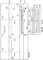
FIG. 5 is an illustration of a method of manufacturing the heat shield panel ofFIG. 4 , in accordance with an embodiment of the disclosure; -
FIG. 6 is an illustration of a method of manufacturing the heat shield panel ofFIG. 4 and is a continuation the method ofFIG. 5 , in accordance with an embodiment of the disclosure; and -
FIG. 7 is an illustration of a method of manufacturing the heat shield panel ofFIG. 4 and is a continuation the method ofFIG. 6 , in accordance with an embodiment of the disclosure. - The detailed description explains embodiments of the present disclosure, together with advantages and features, by way of example with reference to the drawings.
- A detailed description of one or more embodiments of the disclosed apparatus and method are presented herein by way of exemplification and not limitation with reference to the Figures.
- Combustors of gas turbine engines, as well as other components, experience elevated heat levels during operation. Impingement and convective cooling of heat shield panels of the combustor wall may be used to help cool the combustor. Convective cooling may be achieved by air that is channeled between the heat shield panels and a combustion liner of the combustor. Impingement cooling may be a process of directing relatively cool air from a location exterior to the combustor toward a back or underside of the heat shield panels.
- Thus, combustion liners and heat shield panels are utilized to face the extreme temperatures produced by the burning of fuel within a combustion chamber and protect the overall combustor shell. The combustion liners may be supplied with cooling air including dilution passages which deliver a high volume of cooling air into a hot flow path. The cooling air may be air from the compressor of the gas turbine engine. The cooling air may impinge upon a back side of a heat shield panel that faces a combustion liner inside the combustor. Heat shield panels often include cooling apertures configured to transfer air from the cooling channel into a combustion area within the combustion chamber. The performance of the cooling apertures may be enhanced through utilizing complex geometries, however complex geometries may lead to difficulties during conventional methods of manufacturing the heat shield panels, such as, for example investment casting. Embodiments disclosed herein seek to provide a method for manufacturing complex geometries of the heat shield panel.
-
FIG. 1 schematically illustrates agas turbine engine 20. Thegas turbine engine 20 is disclosed herein as a two-spool turbofan that generally incorporates afan section 22, acompressor section 24, acombustor section 26 and aturbine section 28. Alternative engines might include an augmentor section (not shown) among other systems or features. Thefan section 22 drives air along a bypass flow path B in a bypass duct, while thecompressor section 24 drives air along a core flow path C for compression and communication into thecombustor section 26 then expansion through theturbine section 28. Although depicted as a two-spool turbofan gas turbine engine in the disclosed non-limiting embodiment, it should be understood that the concepts described herein are not limited to use with two-spool turbofans as the teachings may be applied to other types of turbine engines including three-spool architectures. - The
exemplary engine 20 generally includes alow speed spool 30 and ahigh speed spool 32 mounted for rotation about an engine central longitudinal axis A relative to an enginestatic structure 36 viaseveral bearing systems 38. It should be understood that various bearingsystems 38 at various locations may alternatively or additionally be provided, and the location of bearingsystems 38 may be varied as appropriate to the application. - The
low speed spool 30 generally includes aninner shaft 40 that interconnects afan 42, alow pressure compressor 44 and alow pressure turbine 46. Theinner shaft 40 is connected to thefan 42 through a speed change mechanism, which in exemplarygas turbine engine 20 is illustrated as a gearedarchitecture 48 to drive thefan 42 at a lower speed than thelow speed spool 30. Thehigh speed spool 32 includes anouter shaft 50 that interconnects ahigh pressure compressor 52 andhigh pressure turbine 54. Acombustor 300 is arranged inexemplary gas turbine 20 between thehigh pressure compressor 52 and thehigh pressure turbine 54. An enginestatic structure 36 is arranged generally between thehigh pressure turbine 54 and thelow pressure turbine 46. The enginestatic structure 36 furthersupports bearing systems 38 in theturbine section 28. Theinner shaft 40 and theouter shaft 50 are concentric and rotate via bearingsystems 38 about the engine central longitudinal axis A which is collinear with their longitudinal axes. - The core airflow is compressed by the
low pressure compressor 44 then thehigh pressure compressor 52, mixed and burned with fuel in thecombustor 300, then expanded over thehigh pressure turbine 54 andlow pressure turbine 46. Theturbines low speed spool 30 andhigh speed spool 32 in response to the expansion. It will be appreciated that each of the positions of thefan section 22,compressor section 24,combustor section 26,turbine section 28, and fandrive gear system 48 may be varied. For example,gear system 48 may be located aft ofcombustor section 26 or even aft ofturbine section 28, andfan section 22 may be positioned forward or aft of the location ofgear system 48. - The
engine 20 in one example is a high-bypass geared aircraft engine. In a further example, theengine 20 bypass ratio is greater than about six (6), with an example embodiment being greater than about ten (10), the gearedarchitecture 48 is an epicyclic gear train, such as a planetary gear system or other gear system, with a gear reduction ratio of greater than about 2.3 and thelow pressure turbine 46 has a pressure ratio that is greater than about five. In one disclosed embodiment, theengine 20 bypass ratio is greater than about ten (10:1), the fan diameter is significantly larger than that of thelow pressure compressor 44, and thelow pressure turbine 46 has a pressure ratio that is greater than about five (5:1).Low pressure turbine 46 pressure ratio is pressure measured prior to inlet oflow pressure turbine 46 as related to the pressure at the outlet of thelow pressure turbine 46 prior to an exhaust nozzle. The gearedarchitecture 48 may be an epicyclic gear train, such as a planetary gear system or other gear system, with a gear reduction ratio of greater than about 2.3:1. It should be understood, however, that the above parameters are only exemplary of one embodiment of a geared architecture engine and that the present disclosure is applicable to other gas turbine engines including direct drive turbofans. - A significant amount of thrust is provided by the bypass flow B due to the high bypass ratio. The
fan section 22 of theengine 20 is designed for a particular flight condition--typically cruise at about 0.8 Mach and about 35,000 feet (10,668 meters). The flight condition of 0.8 Mach and 35,000 ft (10,668 meters), with the engine at its best fuel consumption--also known as "bucket cruise Thrust Specific Fuel Consumption ('TSFC')"--is the industry standard parameter of lbm of fuel being burned divided by lbf of thrust the engine produces at that minimum point. "Low fan pressure ratio" is the pressure ratio across the fan blade alone, without a Fan Exit Guide Vane ("FEGV") system. The low fan pressure ratio as disclosed herein according to one non-limiting embodiment is less than about 1.45. "Low corrected fan tip speed" is the actual fan tip speed in ft/sec divided by an industry standard temperature correction of [(Tram °R)/(518.7 °R)]0.5. The "Low corrected fan tip speed" as disclosed herein according to one non-limiting embodiment is less than about 1150 ft/second (350.5 m/sec). - Referring now to
FIG. 2 and with continued reference toFIG. 1 , thecombustor section 26 of thegas turbine engine 20 is shown. As illustrated, acombustor 300 defines acombustion chamber 302. Thecombustion chamber 302 includes acombustion area 370 within thecombustion chamber 302. Thecombustor 300 includes aninlet 306 and anoutlet 308 through which air may pass. The air may be supplied to thecombustor 300 by a pre-diffuser 110. Air may also enter thecombustion chamber 302 through other holes in thecombustor 300 including, but not limited to, quenchholes 310, as seen inFIG. 2 . - Compressor air is supplied from the
compressor section 24 into a pre-diffuser strut. As will be appreciated by those of skill in the art, the pre-diffuser strut is configured to direct the airflow into the pre-diffuser 110, which then directs the airflow toward thecombustor 300. Thecombustor 300 and the pre-diffuser 110 are separated by ashroud chamber 113 that contains thecombustor 300 and includes aninner diameter branch 114 and anouter diameter branch 116. As air enters theshroud chamber 113, a portion of the air may flow into thecombustor inlet 306, a portion may flow into theinner diameter branch 114, and a portion may flow into theouter diameter branch 116. - The air from the
inner diameter branch 114 and theouter diameter branch 116 may then enter thecombustion chamber 302 by means of one or moreimpingement holes 307 in thecombustion liner 600 and one ormore cooling apertures 309 in theheat shield panels 400. The impingement holes 307 and coolingapertures 309 may include nozzles, holes, etc. The air may then exit thecombustion chamber 302 through thecombustor outlet 308. At the same time, fuel may be supplied into thecombustion chamber 302 from afuel injector 320 and apilot nozzle 322, which may be ignited within thecombustion chamber 302. Thecombustor 300 of theengine combustion section 26 may be housed within ashroud case 124 which may define theshroud chamber 113. - The
combustor 300, as shown inFIG. 2 , includes multipleheat shield panels 400 that are attached to the combustion liner 600 (SeeFIG. 3 ). Theheat shield panels 400 may be arranged parallel to thecombustion liner 600. Thecombustion liner 600 can define circular or annular structures with theheat shield panels 400 being mounted on a radially inward liner and a radially outward liner, as will be appreciated by those of skill in the art. Theheat shield panels 400 can be removably mounted to thecombustion liner 600 by one ormore attachment mechanisms 332. In some embodiments, theattachment mechanism 332 may be integrally formed with a respectiveheat shield panel 400, although other configurations are possible. In some embodiments, theattachment mechanism 332 may be a threaded stud or other structure that may extend from the respectiveheat shield panel 400 through the interior surface to a receiving portion or aperture of thecombustion liner 600 such that theheat shield panel 400 may be attached to thecombustion liner 600 and held in place. Theheat shield panels 400 partially enclose acombustion area 370 within thecombustion chamber 302 of thecombustor 300. - Referring now to
FIGs. 3 and4 with continued reference toFIGs. 1 and2 .FIG. 3 illustrates aheat shield panel 400 andcombustion liner 600 of a combustor 300 (seeFIG. 1 ) of a gas turbine engine 20 (seeFIG. 1 ). Theheat shield panel 400 and thecombustion liner 600 are in a facing spaced relationship. Theheat shield panel 400 includes afirst surface 410 oriented towards thecombustion area 370 of thecombustion chamber 302 and asecond surface 420 opposite thefirst surface 410 oriented towards thecombustion liner 600. Thecombustion liner 600 has aninner surface 610 and anouter surface 620 opposite theinner surface 610. Theinner surface 610 is oriented toward theheat shield panel 400. Theouter surface 620 is oriented outward from thecombustor 300 proximate theinner diameter branch 114 and theouter diameter branch 116. - The
combustion liner 600 includes a plurality of impingement holes 307 configured to allowairflow 590 from theinner diameter branch 114 and theouter diameter branch 116 to enter animpingement cavity 390 in between thecombustion liner 600 and theheat shield panel 400. Each of the impingement holes 307 extend from theouter surface 620 to theinner surface 610 through thecombustion liner 600. - Each of the impingement holes 307 fluidly connects the
impingement cavity 390 to at least one of theinner diameter branch 114 and theouter diameter branch 116. Theheat shield panel 400 may include one ormore cooling apertures 309 configured to allowairflow 590 from theimpingement cavity 390 to thecombustion area 370 of thecombustion chamber 302. - Each of the cooling
apertures 309 extend from thesecond surface 420 to thefirst surface 410 through theheat shield panel 400.Airflow 590 flowing into theimpingement cavity 390 impinges on thesecond surface 420 of theheat shield panel 400 and absorbs heat from theheat shield panel 400 as it impinges on thesecond surface 420. - As shown in
FIG. 4 , theheat shield panel 400 contains complex features that may need to be formed during the manufacturing process of theheat shield panel 400. The complex features may include theattachment mechanisms 332 extending away from thesecond surface 420 of theheat shield panel 400. As shown inFIG. 4 , the attachment features 332 may be threaded studs. The complex features may also include the quench holes 310, which may be circular in shape, as shown inFIG. 4 . The quench holes 310 may be oriented about perpendicular to thesecond surface 420 of theheat shield panel 400. The complex features may further include the coolingapertures 309, which also may be circular in shape, as shown inFIG. 4 . The coolingapertures 309, may be oriented non-perpendicular to thesecond surface 420 of theheat shield panel 400. - The
heat shield panel 400 is typically manufactured using an investment casting process. To cast theheat shield panels 400 by investment casting, wax needs to be injected into a tool to create wax patterns that will be used to create a ceramic casting mold, which will then be used to cast the metalheat shield panels 400. Havingheat shield panels 400 designs with the attachment features 332 that have integral cast threads about parallel (i.e., normal to the stud of the attachment feature 332) to thesecond surface 420 of theheat shield panel 400 complicates the investment casting process since the threads of theattachment feature 332 cannot be injected directly with theheat shield panels 400 since the angle of the studs and the threads of the attachment features 332 will back lock in the die, which makes it difficult to remove the wax pattern from the injection die. Thus, the threads of the attachment features 332 need to be injected separately in wax and then wax welded to the wax pattern. Casting theheat shield panel 400 and threads of the attachment features 332 separately leads to casting difficulty and quality issues with thread alignment, thread integrity (free from defects like porosity or stray grains), and thread dimensional conformance. This leads to higher process and component cost. Further, the coolingapertures 309 may be oriented at a non-normal angle to thesecond surface 420 of theheat shield panel 400 or have complex geometries, which make manufacturing thecooling apertures 309 difficult through an investment casting process and other conventional methods. - The cooling
apertures 309 may be conventionally formed by various manufacturing methods including but not limited to laser-drilling and electrical discharge machining (EDM) after theheat shield panel 400 has gone through the investment casting process. These methods may be time-intensive and may only create afew cooling apertures 309 at a time. Conventional manufacturing processes (e.g., investment casting process) may only be able to produce simple linear holes, as shown by 309a inFIG. 3 . The simple linear holes may have straight linear side walls and at most oneturn 311, as shown by 309b inFIG. 3 . For example, the coolingapertures 309 at 309b may be produced by drilling two linear holes include one from thefirst surface 410 and one fromsecond surface 420. Coolingapertures 309 with complex geometries may be formed usingmethod 700 discussed below. - Complex geometries may include two or more turns 311, as shown at 309c and 309d in
FIG. 3 . Complex geometries may includecurvilinear side walls 312, as shown at 309c and 309e inFIG. 3 . Thecurvilinear side walls 312 may be designed to accelerate or decelerate theairflow 590 through the coolingapertures 309. - Complex geometries may include complex shaped
airflow passageways 316 to maximize the surface areas for heat flow between theairflow 590 and theheat shield panel 400. Complexshape airflow passageways 316 may include but are not limited to spiralpassageways 316 shown at 309c inFIG. 3 and zig-zag passageways 316 shown at 309d inFIG. 3 . Complex shapedairflow passageways 316 may include also include branchingpassageways 316 that branch out in to two ormore passageways 316, as shown at 309f inFIG. 3 . Additionally, complexshape airflow passageways 316 inFigure 3a may include also include branchingpassageways 316 that branch out in to two ormore passageways 316, as shown in 309g. The branchingpassageways 316 may branch out intopassageways 316 about parallel to thefirst surface 410 and/or thesecond surface 420. The branchingpassageways 316 may branch out intopassageways 316 about parallel to thefirst surface 410 and/or thesecond surface 420 on one or more different planes within theheat shield panel 400, as shown at 309g. Thepassages 316 may interconnect at the inlet 309-1 and/or outlets 309-2 as shown at 309h, interconnect at other points 309-3 as shown at 309i, or not interconnect as shown at 309j. The branchingpassageways 316 may also fluidly connect two or moredifferent cooling apertures 309. - Advantageously, the
method 700 described below allows for fabrication of much morecomplex cooling apertures 309 than conventional methods, which allows for increase surface area of the cooling apertures resulting in greater overall cooling efficiency for the heat shield panel. - Embodiments disclosed herein seek to address the challenges of manufacturing a
heat shield panel 400 using the Tomo Lithographic Molding (TLM) process developed by Mikro Systems, Inc. of Charlottesville, VA as described in patentUS 9,879,861 B2 heat shield panel 400 in layers without the use of castings or cores to produce molds. Advantageously, theheat shield panel 400 is created with the complex features described above during the TLM process without the post processing required by investment casting. - Referring now to
FIGs. 5-7 , with continued reference toFIGs. 1-4 .FIG. 5-8 illustrates amethod 700 of manufacturing theheat shield panel 400. Atblock 704, a plurality oflayers 850 to compose aheat shield panel 400 are determined, which may include segmenting a model of the heat shield panel into a plurality of layers.Block 704 may further include digitally slicing a computer-aided design (CAD) model of theheat shield panel 400 intolayers 850. Eachlayer 850 represents a three-dimensional slice of theheat shield panel 400 such that when assembled (e.g., laid on top of each other and curved) thelayers 850 combine to form theheat shield panel 400. Eachlayer 850 may be the same thickness or thelayers 850 may vary in thickness. - At
block 706, thelayers 850 are formed by in each of thesheets 860. Thesheets 860 may be composed of patterned nickel super-alloy foil. In embodiment, the features may be formed in thefoil 860 by any standard available means of machining or patterning metal foils including at least one of chemically etching eachsheet 860, photochemically etching eachsheet 860, stamping eachsheet 860, laser cutting eachsheet 860, water jet cutting eachsheet 860, and wire or plunge electrical discharge machining eachsheet 860. In an embodiment, the features may be formed in thefoil 860 by etching features of thelayer 850 into asheet 860. The features of eachsheet 860 may be different. Features may include at least one ofcooling apertures 309, quenchholes 310, andattachment mechanisms 332. For example, onesheet 860 may contain features such as the coolingapertures 309, whereas anothersheet 860 may contain features such as quenchholes 310, whereas anothersheet 860 may contain features such as theattachment mechanisms 332. Thesheets 860 may each include one or moreremovable portions 852 proximate theouter edges 854 of thesheet 860. Each of theremovable portions 854 may include guideholes 856 that aid in the alignment of thesheets 860 later in themethod 700, as discussed below. - At
block 708, eachsheet 860 is formed as a three-dimensional slice of theheat shield panel 400. The forming may include flatting and/or curving eachsheet 860 as appropriate for theheat shield panel 400. For example, someheat shield panels 400 may be flat, someheat shield panels 400 may be curved, and someheat shield panels 400 may be both flat and curved in different areas of theheat shield panels 400. Eachsheet 860 may be curved individually or thesheets 860 may be curved in unison when stacking atblock 710. - At
block 710, thesheets 860 of etchedpattern foil 860 are stacked. Thesheets 860 may be stacked onto anegative template 900 of theheat shield panel 400. In an embodiment, thenegative template 900 of theheat shield panel 400 is configured to curve each of thesheets 860 into a three-dimensional slice of theheat shield panel 400 inblock 708, thus block 708 may be performed simultaneously to block 710 or afterblock 710. - The
negative template 900 may also be configured to align thesheets 860. Thenegative templates 900 may include one ormore studs 910 configured to align thesheets 850. In an embodiment, as shown inFIG. 6 , thenegative template 900 of theheat shield panel 400 is configured to align each of thesheets 860 by stacking the sheets onto thenegative template 900 such that thestuds 910 are inserted throughguide holes 856 in one or moreremovable portions 852 of the sheet proximateouter edges 854 of thesheet 860. In another embodiment, thestuds 910 are oriented to line up with the quench holes 310 and thenegative template 900 of theheat shield panel 400 is configured to align each of thesheets 860 by stacking thesheets 860 onto thenegative template 900, such that thestuds 910 are inserted through the quench holes 310. - At
block 712, thesheets 860 of the etchedpattern foil 860 are joined together. Conventional TLM processes may utilize an adhesive to join thesheets 860 together atblock 712 however, due to the elevated temperature environment of the a combustor 300 a more heat-tolerant bonding method must be utilized. Thesheets 860 may be joined together through various methods including but not limited to at least one of: diffusion bonding thesheets 860 together, cold welding thesheets 860 together, ultrasonic metal welding thesheets 860 together, or other solid state welding method thesheets 860 together. In an embodiment, thesheets 860 may be joined together through diffusion bonding. Themethod 700 may further include removing theremovable portions 852 of thesheets 860 after thesheets 860 have been joined together. Theremovable portions 852 may be removed by laser cutting, water jet cutting, wire or plunge electrical discharge machining, conventional milling, or other method of metal cutting known to one of skill in the art. - Technical effects of embodiments of the present disclosure include forming a heat panel by dividing a model of the heat shield panel into a plurality of layers, etching the feature of each of the plurality of layers on to separate sheets, stacking the sheet and then joining the sheets together.
- The term "about" is intended to include the degree of error associated with measurement of the particular quantity based upon the equipment available at the time of filing the application. For example, "about" can include a non-limiting range of ± 8% or 5%, or 2% of a given value.
- The terminology used herein is for the purpose of describing particular embodiments only and is not intended to be limiting of the present disclosure. As used herein, the singular forms "a", "an" and "the" are intended to include the plural forms as well, unless the context clearly indicates otherwise. It will be further understood that the terms "comprises" and/or "comprising," when used in this specification, specify the presence of stated features, integers, steps, operations, elements, and/or components, but do not preclude the presence or addition of one or more other features, integers, steps, operations, element components, and/or groups thereof.
- While the present disclosure has been described with reference to an exemplary embodiment or embodiments, it will be understood by those skilled in the art that various changes may be made and equivalents may be substituted for elements thereof without departing from the scope of the present disclosure. In addition, many modifications may be made to adapt a particular situation or material to the teachings of the present disclosure without departing from the essential scope thereof. Therefore, it is intended that the present disclosure not be limited to the particular embodiment disclosed as the best mode contemplated for carrying out this present disclosure, but that the present disclosure will include all embodiments falling within the scope of the claims.
Claims (15)
- A method (700) of manufacturing a heat shield panel (400) for a gas turbine engine (20), the method comprising:determining (704) a plurality of layers (850) to compose the heat shield panel having one or more cooling apertures (309) with complex geometries;forming (706) each of the plurality of layers into sheets (860);forming (708) each of the sheets into a three-dimensional slice of the heat shield panel;stacking (710) each of the sheets to form a three-dimensional heat shield panel; andjoining (712) the sheets together,
- The method of claim 1, wherein the complex geometries comprise at least one of a spiral passageway (309c), a zig-zag passageway (309d), a branching passageway (309f), a passageway (309c, 309d) with two or more turns (311), and a passageway (309c) with a curvilinear side wall (312).
- The method of claim 1 or claim 2, wherein each sheet (860) is composed of patterned foil.
- The method of claim 3, wherein forming (706) each of the plurality of layers (850) into sheets (860) further comprises at least one of chemically etching each of the sheets, photochemically etching each of the sheets, stamping each of the sheets, laser cutting each of the sheets, water jet cutting each of the sheets, and wire or plunge electrical discharge machining each of the sheets; optionally wherein forming further comprises chemically etching each of the sheets.
- The method of claim 4, wherein features of each layer (850) are etched into the sheets (860).
- The method of claim 5, wherein the features include at least one of one of cooling apertures (309), quench holes (310), and an attachment mechanism (332); optionally wherein the attachment mechanism is a threaded stud.
- The method of any preceding claim, wherein each sheet (860) is curved individually.
- The method of claim 6 or claim 7, wherein the sheets (860) are stacked onto a negative template (900) of the heat shield panel (400).
- The method of claim 8, wherein the negative template (900) of the heat shield panel (400) is configured to curve each of the sheets (860) into a three-dimensional slice of the heat shield panel.
- The method of claim 8 or claim 9, wherein the negative template (900) of the heat shield panel (400) is configured to align each of the sheets (860).
- The method of claim 10, wherein the negative template (900) includes studs (910) and the negative template of the heat shield panel (400) is configured to align each of the sheets (860) by stacking the sheets onto the negative template such that the studs are inserted through the quench holes (310).
- The method of claim 10, wherein the negative template includes studs and the negative template of the heat shield panel is configured to align each of the sheets by stacking the sheets onto the negative template such that the studs are inserted through guide holes (856) in one or more removable portions (852) of the sheet proximate outer edges of the sheet; and optionally wherein the method further comprises removing the removable portions from the sheets after they have been joined together.
- The method of any preceding claim, wherein joining (712) the sheets (860) together further comprises at least one of diffusion bonding the sheets together, cold welding the sheets together, ultrasonic metal welding the sheets together, and other solid state welding method the sheets together; optionally wherein joining the sheets together further comprises diffusion bonding the sheets together.
- A heat shield panel (400) for a gas turbine engine (20) manufactured by the method of claim 1, the heat shield panel comprising:a first surface (410);a second surface (420) opposite the first surface; anda plurality of cooling apertures (309) extending from the first surface to the second surface through the heat shield panel, wherein each of the plurality of cooling apertures are oriented at a non-normal angle relative to the second surface.
- The heat shield panel of claim 14, further comprising:
one or more threaded studs (332) extending away from the second surface (420) of the heat shield panel (400); and/or further comprising:
one or more quench holes (310) extending from the first surface (410) to the second surface through the heat shield panel.
Applications Claiming Priority (1)
| Application Number | Priority Date | Filing Date | Title |
|---|---|---|---|
| US16/021,385 US11035572B2 (en) | 2018-06-28 | 2018-06-28 | Heat shield panel manufacturing process |
Publications (2)
| Publication Number | Publication Date |
|---|---|
| EP3587927A1 true EP3587927A1 (en) | 2020-01-01 |
| EP3587927B1 EP3587927B1 (en) | 2022-02-16 |
Family
ID=67137754
Family Applications (1)
| Application Number | Title | Priority Date | Filing Date |
|---|---|---|---|
| EP19183457.1A Active EP3587927B1 (en) | 2018-06-28 | 2019-06-28 | Heat shield panel manufacturing process and heat shield panel |
Country Status (2)
| Country | Link |
|---|---|
| US (2) | US11035572B2 (en) |
| EP (1) | EP3587927B1 (en) |
Cited By (1)
| Publication number | Priority date | Publication date | Assignee | Title |
|---|---|---|---|---|
| US10995955B2 (en) | 2018-08-01 | 2021-05-04 | Raytheon Technologies Corporation | Combustor panel |
Families Citing this family (2)
| Publication number | Priority date | Publication date | Assignee | Title |
|---|---|---|---|---|
| CN114134560A (en) * | 2021-11-01 | 2022-03-04 | 宁晋晶兴电子材料有限公司 | Method for filling heat preservation felt into containing cavity of guide cylinder and guide cylinder |
| JP7780333B2 (en) * | 2021-12-27 | 2025-12-04 | 川崎重工業株式会社 | Combustor panel and gas turbine combustor equipped with same |
Citations (5)
| Publication number | Priority date | Publication date | Assignee | Title |
|---|---|---|---|---|
| US5499499A (en) * | 1993-10-06 | 1996-03-19 | Societe Nationale D'etude Et De Construction De Moteurs D'aviation | Cladded combustion chamber construction |
| EP1635119A2 (en) * | 2004-09-09 | 2006-03-15 | United Technologies Corporation | Cooled turbine engine components |
| EP2716396A1 (en) * | 2011-05-24 | 2014-04-09 | Mitsubishi Heavy Industries, Ltd. | Hollow curved plate, method for manufacturing same, and burner for gas turbine |
| EP3112755A1 (en) * | 2015-06-30 | 2017-01-04 | Rolls-Royce Corporation | Combustor tile |
| US9879861B2 (en) | 2013-03-15 | 2018-01-30 | Rolls-Royce Corporation | Gas turbine engine with improved combustion liner |
Family Cites Families (2)
| Publication number | Priority date | Publication date | Assignee | Title |
|---|---|---|---|---|
| US5737922A (en) * | 1995-01-30 | 1998-04-14 | Aerojet General Corporation | Convectively cooled liner for a combustor |
| WO2014143209A1 (en) | 2013-03-15 | 2014-09-18 | Rolls-Royce Corporation | Gas turbine engine combustor liner |
-
2018
- 2018-06-28 US US16/021,385 patent/US11035572B2/en active Active
-
2019
- 2019-06-28 EP EP19183457.1A patent/EP3587927B1/en active Active
-
2021
- 2021-05-25 US US17/329,671 patent/US20210278084A1/en active Granted
Patent Citations (5)
| Publication number | Priority date | Publication date | Assignee | Title |
|---|---|---|---|---|
| US5499499A (en) * | 1993-10-06 | 1996-03-19 | Societe Nationale D'etude Et De Construction De Moteurs D'aviation | Cladded combustion chamber construction |
| EP1635119A2 (en) * | 2004-09-09 | 2006-03-15 | United Technologies Corporation | Cooled turbine engine components |
| EP2716396A1 (en) * | 2011-05-24 | 2014-04-09 | Mitsubishi Heavy Industries, Ltd. | Hollow curved plate, method for manufacturing same, and burner for gas turbine |
| US9879861B2 (en) | 2013-03-15 | 2018-01-30 | Rolls-Royce Corporation | Gas turbine engine with improved combustion liner |
| EP3112755A1 (en) * | 2015-06-30 | 2017-01-04 | Rolls-Royce Corporation | Combustor tile |
Cited By (2)
| Publication number | Priority date | Publication date | Assignee | Title |
|---|---|---|---|---|
| US10995955B2 (en) | 2018-08-01 | 2021-05-04 | Raytheon Technologies Corporation | Combustor panel |
| EP3604927B1 (en) * | 2018-08-01 | 2023-04-05 | Raytheon Technologies Corporation | Liner assembly for use in a combustor of a gas turbine engine combustor panel |
Also Published As
| Publication number | Publication date |
|---|---|
| EP3587927B1 (en) | 2022-02-16 |
| US20200003419A1 (en) | 2020-01-02 |
| US20210278084A1 (en) | 2021-09-09 |
| US11035572B2 (en) | 2021-06-15 |
Similar Documents
| Publication | Publication Date | Title |
|---|---|---|
| US12312975B2 (en) | Component for a turbine engine with a cooling hole | |
| US10830437B1 (en) | Backside features with intermitted pin fins | |
| EP3757352B1 (en) | Method for forming an airfoil with internal cavities | |
| US20210278084A1 (en) | Heat shield panel manufacturing process | |
| US20170234138A1 (en) | Airfoil Trailing Edge Cooling | |
| EP3734161B1 (en) | Gas turbine engine combustor comprising a liner panel with micro-circuit core cooling | |
| US11702987B2 (en) | Baffle with two datum features | |
| EP2998511B1 (en) | Cooling passage with surface features | |
| US20200263607A1 (en) | Backside features with intermitted pin fins | |
| EP3757351B1 (en) | Method for manufacturing an airfoil | |
| EP3564485B1 (en) | Airfoils, cores, and methods of manufacture for forming airfoils having fluidly connected platform cooling circuits | |
| US11905854B2 (en) | Two-piece baffle | |
| EP3748133B1 (en) | Fatigue resistant blade outer air seal | |
| EP3623575B1 (en) | Serpentine turn cover for gas turbine stator vane assembly | |
| EP3708776A1 (en) | Gasturbine airfoils having tapered tip flag cavity and cores for forming the same | |
| EP3550110B1 (en) | Airfoil having leading edge cooling scheme with backstrike compensation |
Legal Events
| Date | Code | Title | Description |
|---|---|---|---|
| PUAI | Public reference made under article 153(3) epc to a published international application that has entered the european phase |
Free format text: ORIGINAL CODE: 0009012 |
|
| STAA | Information on the status of an ep patent application or granted ep patent |
Free format text: STATUS: THE APPLICATION HAS BEEN PUBLISHED |
|
| AK | Designated contracting states |
Kind code of ref document: A1 Designated state(s): AL AT BE BG CH CY CZ DE DK EE ES FI FR GB GR HR HU IE IS IT LI LT LU LV MC MK MT NL NO PL PT RO RS SE SI SK SM TR |
|
| AX | Request for extension of the european patent |
Extension state: BA ME |
|
| STAA | Information on the status of an ep patent application or granted ep patent |
Free format text: STATUS: REQUEST FOR EXAMINATION WAS MADE |
|
| 17P | Request for examination filed |
Effective date: 20200626 |
|
| RBV | Designated contracting states (corrected) |
Designated state(s): AL AT BE BG CH CY CZ DE DK EE ES FI FR GB GR HR HU IE IS IT LI LT LU LV MC MK MT NL NO PL PT RO RS SE SI SK SM TR |
|
| STAA | Information on the status of an ep patent application or granted ep patent |
Free format text: STATUS: EXAMINATION IS IN PROGRESS |
|
| 17Q | First examination report despatched |
Effective date: 20201109 |
|
| RAP1 | Party data changed (applicant data changed or rights of an application transferred) |
Owner name: RAYTHEON TECHNOLOGIES CORPORATION |
|
| GRAP | Despatch of communication of intention to grant a patent |
Free format text: ORIGINAL CODE: EPIDOSNIGR1 |
|
| STAA | Information on the status of an ep patent application or granted ep patent |
Free format text: STATUS: GRANT OF PATENT IS INTENDED |
|
| INTG | Intention to grant announced |
Effective date: 20210902 |
|
| GRAS | Grant fee paid |
Free format text: ORIGINAL CODE: EPIDOSNIGR3 |
|
| GRAA | (expected) grant |
Free format text: ORIGINAL CODE: 0009210 |
|
| STAA | Information on the status of an ep patent application or granted ep patent |
Free format text: STATUS: THE PATENT HAS BEEN GRANTED |
|
| AK | Designated contracting states |
Kind code of ref document: B1 Designated state(s): AL AT BE BG CH CY CZ DE DK EE ES FI FR GB GR HR HU IE IS IT LI LT LU LV MC MK MT NL NO PL PT RO RS SE SI SK SM TR |
|
| REG | Reference to a national code |
Ref country code: GB Ref legal event code: FG4D |
|
| REG | Reference to a national code |
Ref country code: CH Ref legal event code: EP |
|
| REG | Reference to a national code |
Ref country code: DE Ref legal event code: R096 Ref document number: 602019011605 Country of ref document: DE |
|
| REG | Reference to a national code |
Ref country code: AT Ref legal event code: REF Ref document number: 1469100 Country of ref document: AT Kind code of ref document: T Effective date: 20220315 |
|
| REG | Reference to a national code |
Ref country code: IE Ref legal event code: FG4D |
|
| REG | Reference to a national code |
Ref country code: LT Ref legal event code: MG9D |
|
| REG | Reference to a national code |
Ref country code: AT Ref legal event code: MK05 Ref document number: 1469100 Country of ref document: AT Kind code of ref document: T Effective date: 20220216 |
|
| PG25 | Lapsed in a contracting state [announced via postgrant information from national office to epo] |
Ref country code: SE Free format text: LAPSE BECAUSE OF FAILURE TO SUBMIT A TRANSLATION OF THE DESCRIPTION OR TO PAY THE FEE WITHIN THE PRESCRIBED TIME-LIMIT Effective date: 20220216 Ref country code: RS Free format text: LAPSE BECAUSE OF FAILURE TO SUBMIT A TRANSLATION OF THE DESCRIPTION OR TO PAY THE FEE WITHIN THE PRESCRIBED TIME-LIMIT Effective date: 20220216 Ref country code: PT Free format text: LAPSE BECAUSE OF FAILURE TO SUBMIT A TRANSLATION OF THE DESCRIPTION OR TO PAY THE FEE WITHIN THE PRESCRIBED TIME-LIMIT Effective date: 20220616 Ref country code: NO Free format text: LAPSE BECAUSE OF FAILURE TO SUBMIT A TRANSLATION OF THE DESCRIPTION OR TO PAY THE FEE WITHIN THE PRESCRIBED TIME-LIMIT Effective date: 20220516 Ref country code: NL Free format text: LAPSE BECAUSE OF FAILURE TO SUBMIT A TRANSLATION OF THE DESCRIPTION OR TO PAY THE FEE WITHIN THE PRESCRIBED TIME-LIMIT Effective date: 20220216 Ref country code: LT Free format text: LAPSE BECAUSE OF FAILURE TO SUBMIT A TRANSLATION OF THE DESCRIPTION OR TO PAY THE FEE WITHIN THE PRESCRIBED TIME-LIMIT Effective date: 20220216 Ref country code: HR Free format text: LAPSE BECAUSE OF FAILURE TO SUBMIT A TRANSLATION OF THE DESCRIPTION OR TO PAY THE FEE WITHIN THE PRESCRIBED TIME-LIMIT Effective date: 20220216 Ref country code: ES Free format text: LAPSE BECAUSE OF FAILURE TO SUBMIT A TRANSLATION OF THE DESCRIPTION OR TO PAY THE FEE WITHIN THE PRESCRIBED TIME-LIMIT Effective date: 20220216 Ref country code: BG Free format text: LAPSE BECAUSE OF FAILURE TO SUBMIT A TRANSLATION OF THE DESCRIPTION OR TO PAY THE FEE WITHIN THE PRESCRIBED TIME-LIMIT Effective date: 20220516 |
|
| PG25 | Lapsed in a contracting state [announced via postgrant information from national office to epo] |
Ref country code: PL Free format text: LAPSE BECAUSE OF FAILURE TO SUBMIT A TRANSLATION OF THE DESCRIPTION OR TO PAY THE FEE WITHIN THE PRESCRIBED TIME-LIMIT Effective date: 20220216 Ref country code: LV Free format text: LAPSE BECAUSE OF FAILURE TO SUBMIT A TRANSLATION OF THE DESCRIPTION OR TO PAY THE FEE WITHIN THE PRESCRIBED TIME-LIMIT Effective date: 20220216 Ref country code: GR Free format text: LAPSE BECAUSE OF FAILURE TO SUBMIT A TRANSLATION OF THE DESCRIPTION OR TO PAY THE FEE WITHIN THE PRESCRIBED TIME-LIMIT Effective date: 20220517 Ref country code: FI Free format text: LAPSE BECAUSE OF FAILURE TO SUBMIT A TRANSLATION OF THE DESCRIPTION OR TO PAY THE FEE WITHIN THE PRESCRIBED TIME-LIMIT Effective date: 20220216 Ref country code: AT Free format text: LAPSE BECAUSE OF FAILURE TO SUBMIT A TRANSLATION OF THE DESCRIPTION OR TO PAY THE FEE WITHIN THE PRESCRIBED TIME-LIMIT Effective date: 20220216 |
|
| PG25 | Lapsed in a contracting state [announced via postgrant information from national office to epo] |
Ref country code: IS Free format text: LAPSE BECAUSE OF FAILURE TO SUBMIT A TRANSLATION OF THE DESCRIPTION OR TO PAY THE FEE WITHIN THE PRESCRIBED TIME-LIMIT Effective date: 20220617 |
|
| PG25 | Lapsed in a contracting state [announced via postgrant information from national office to epo] |
Ref country code: SM Free format text: LAPSE BECAUSE OF FAILURE TO SUBMIT A TRANSLATION OF THE DESCRIPTION OR TO PAY THE FEE WITHIN THE PRESCRIBED TIME-LIMIT Effective date: 20220216 Ref country code: SK Free format text: LAPSE BECAUSE OF FAILURE TO SUBMIT A TRANSLATION OF THE DESCRIPTION OR TO PAY THE FEE WITHIN THE PRESCRIBED TIME-LIMIT Effective date: 20220216 Ref country code: RO Free format text: LAPSE BECAUSE OF FAILURE TO SUBMIT A TRANSLATION OF THE DESCRIPTION OR TO PAY THE FEE WITHIN THE PRESCRIBED TIME-LIMIT Effective date: 20220216 Ref country code: EE Free format text: LAPSE BECAUSE OF FAILURE TO SUBMIT A TRANSLATION OF THE DESCRIPTION OR TO PAY THE FEE WITHIN THE PRESCRIBED TIME-LIMIT Effective date: 20220216 Ref country code: DK Free format text: LAPSE BECAUSE OF FAILURE TO SUBMIT A TRANSLATION OF THE DESCRIPTION OR TO PAY THE FEE WITHIN THE PRESCRIBED TIME-LIMIT Effective date: 20220216 Ref country code: CZ Free format text: LAPSE BECAUSE OF FAILURE TO SUBMIT A TRANSLATION OF THE DESCRIPTION OR TO PAY THE FEE WITHIN THE PRESCRIBED TIME-LIMIT Effective date: 20220216 |
|
| REG | Reference to a national code |
Ref country code: DE Ref legal event code: R097 Ref document number: 602019011605 Country of ref document: DE |
|
| PG25 | Lapsed in a contracting state [announced via postgrant information from national office to epo] |
Ref country code: AL Free format text: LAPSE BECAUSE OF FAILURE TO SUBMIT A TRANSLATION OF THE DESCRIPTION OR TO PAY THE FEE WITHIN THE PRESCRIBED TIME-LIMIT Effective date: 20220216 |
|
| PLBE | No opposition filed within time limit |
Free format text: ORIGINAL CODE: 0009261 |
|
| STAA | Information on the status of an ep patent application or granted ep patent |
Free format text: STATUS: NO OPPOSITION FILED WITHIN TIME LIMIT |
|
| 26N | No opposition filed |
Effective date: 20221117 |
|
| PG25 | Lapsed in a contracting state [announced via postgrant information from national office to epo] |
Ref country code: MC Free format text: LAPSE BECAUSE OF FAILURE TO SUBMIT A TRANSLATION OF THE DESCRIPTION OR TO PAY THE FEE WITHIN THE PRESCRIBED TIME-LIMIT Effective date: 20220216 |
|
| REG | Reference to a national code |
Ref country code: CH Ref legal event code: PL |
|
| REG | Reference to a national code |
Ref country code: BE Ref legal event code: MM Effective date: 20220630 |
|
| PG25 | Lapsed in a contracting state [announced via postgrant information from national office to epo] |
Ref country code: SI Free format text: LAPSE BECAUSE OF FAILURE TO SUBMIT A TRANSLATION OF THE DESCRIPTION OR TO PAY THE FEE WITHIN THE PRESCRIBED TIME-LIMIT Effective date: 20220216 |
|
| PG25 | Lapsed in a contracting state [announced via postgrant information from national office to epo] |
Ref country code: LU Free format text: LAPSE BECAUSE OF NON-PAYMENT OF DUE FEES Effective date: 20220628 Ref country code: LI Free format text: LAPSE BECAUSE OF NON-PAYMENT OF DUE FEES Effective date: 20220630 Ref country code: IE Free format text: LAPSE BECAUSE OF NON-PAYMENT OF DUE FEES Effective date: 20220628 Ref country code: CH Free format text: LAPSE BECAUSE OF NON-PAYMENT OF DUE FEES Effective date: 20220630 |
|
| PG25 | Lapsed in a contracting state [announced via postgrant information from national office to epo] |
Ref country code: BE Free format text: LAPSE BECAUSE OF NON-PAYMENT OF DUE FEES Effective date: 20220630 |
|
| P01 | Opt-out of the competence of the unified patent court (upc) registered |
Effective date: 20230521 |
|
| PG25 | Lapsed in a contracting state [announced via postgrant information from national office to epo] |
Ref country code: IT Free format text: LAPSE BECAUSE OF FAILURE TO SUBMIT A TRANSLATION OF THE DESCRIPTION OR TO PAY THE FEE WITHIN THE PRESCRIBED TIME-LIMIT Effective date: 20220216 |
|
| PG25 | Lapsed in a contracting state [announced via postgrant information from national office to epo] |
Ref country code: MK Free format text: LAPSE BECAUSE OF FAILURE TO SUBMIT A TRANSLATION OF THE DESCRIPTION OR TO PAY THE FEE WITHIN THE PRESCRIBED TIME-LIMIT Effective date: 20220216 Ref country code: CY Free format text: LAPSE BECAUSE OF FAILURE TO SUBMIT A TRANSLATION OF THE DESCRIPTION OR TO PAY THE FEE WITHIN THE PRESCRIBED TIME-LIMIT Effective date: 20220216 |
|
| PG25 | Lapsed in a contracting state [announced via postgrant information from national office to epo] |
Ref country code: HU Free format text: LAPSE BECAUSE OF FAILURE TO SUBMIT A TRANSLATION OF THE DESCRIPTION OR TO PAY THE FEE WITHIN THE PRESCRIBED TIME-LIMIT; INVALID AB INITIO Effective date: 20190628 |
|
| PG25 | Lapsed in a contracting state [announced via postgrant information from national office to epo] |
Ref country code: TR Free format text: LAPSE BECAUSE OF FAILURE TO SUBMIT A TRANSLATION OF THE DESCRIPTION OR TO PAY THE FEE WITHIN THE PRESCRIBED TIME-LIMIT Effective date: 20220216 |
|
| PG25 | Lapsed in a contracting state [announced via postgrant information from national office to epo] |
Ref country code: MT Free format text: LAPSE BECAUSE OF FAILURE TO SUBMIT A TRANSLATION OF THE DESCRIPTION OR TO PAY THE FEE WITHIN THE PRESCRIBED TIME-LIMIT Effective date: 20220216 |
|
| PGFP | Annual fee paid to national office [announced via postgrant information from national office to epo] |
Ref country code: DE Payment date: 20250520 Year of fee payment: 7 |
|
| PGFP | Annual fee paid to national office [announced via postgrant information from national office to epo] |
Ref country code: GB Payment date: 20250520 Year of fee payment: 7 |
|
| PGFP | Annual fee paid to national office [announced via postgrant information from national office to epo] |
Ref country code: FR Payment date: 20250520 Year of fee payment: 7 |
|
| REG | Reference to a national code |
Ref country code: DE Ref legal event code: R081 Ref document number: 602019011605 Country of ref document: DE Owner name: RTX CORPORATION (N.D.GES.D. STAATES DELAWARE),, US Free format text: FORMER OWNER: RAYTHEON TECHNOLOGIES CORPORATION, FARMINGTON, CT, US |