EP3587921A2 - Electrostatic flame control technology - Google Patents
Electrostatic flame control technology Download PDFInfo
- Publication number
- EP3587921A2 EP3587921A2 EP19183017.3A EP19183017A EP3587921A2 EP 3587921 A2 EP3587921 A2 EP 3587921A2 EP 19183017 A EP19183017 A EP 19183017A EP 3587921 A2 EP3587921 A2 EP 3587921A2
- Authority
- EP
- European Patent Office
- Prior art keywords
- fuel
- electrical charge
- combustor
- component
- charged
- Prior art date
- Legal status (The legal status is an assumption and is not a legal conclusion. Google has not performed a legal analysis and makes no representation as to the accuracy of the status listed.)
- Granted
Links
Images




Classifications
-
- F—MECHANICAL ENGINEERING; LIGHTING; HEATING; WEAPONS; BLASTING
- F02—COMBUSTION ENGINES; HOT-GAS OR COMBUSTION-PRODUCT ENGINE PLANTS
- F02M—SUPPLYING COMBUSTION ENGINES IN GENERAL WITH COMBUSTIBLE MIXTURES OR CONSTITUENTS THEREOF
- F02M27/00—Apparatus for treating combustion-air, fuel, or fuel-air mixture, by catalysts, electric means, magnetism, rays, sound waves, or the like
- F02M27/04—Apparatus for treating combustion-air, fuel, or fuel-air mixture, by catalysts, electric means, magnetism, rays, sound waves, or the like by electric means, ionisation, polarisation or magnetism
-
- F—MECHANICAL ENGINEERING; LIGHTING; HEATING; WEAPONS; BLASTING
- F02—COMBUSTION ENGINES; HOT-GAS OR COMBUSTION-PRODUCT ENGINE PLANTS
- F02B—INTERNAL-COMBUSTION PISTON ENGINES; COMBUSTION ENGINES IN GENERAL
- F02B23/00—Other engines characterised by special shape or construction of combustion chambers to improve operation
- F02B23/08—Other engines characterised by special shape or construction of combustion chambers to improve operation with positive ignition
- F02B23/10—Other engines characterised by special shape or construction of combustion chambers to improve operation with positive ignition with separate admission of air and fuel into cylinder
- F02B23/101—Other engines characterised by special shape or construction of combustion chambers to improve operation with positive ignition with separate admission of air and fuel into cylinder the injector being placed on or close to the cylinder centre axis, e.g. with mixture formation using spray guided concepts
-
- F—MECHANICAL ENGINEERING; LIGHTING; HEATING; WEAPONS; BLASTING
- F02—COMBUSTION ENGINES; HOT-GAS OR COMBUSTION-PRODUCT ENGINE PLANTS
- F02B—INTERNAL-COMBUSTION PISTON ENGINES; COMBUSTION ENGINES IN GENERAL
- F02B51/00—Other methods of operating engines involving pretreating of, or adding substances to, combustion air, fuel, or fuel-air mixture of the engines
- F02B51/04—Other methods of operating engines involving pretreating of, or adding substances to, combustion air, fuel, or fuel-air mixture of the engines involving electricity or magnetism
-
- F—MECHANICAL ENGINEERING; LIGHTING; HEATING; WEAPONS; BLASTING
- F02—COMBUSTION ENGINES; HOT-GAS OR COMBUSTION-PRODUCT ENGINE PLANTS
- F02M—SUPPLYING COMBUSTION ENGINES IN GENERAL WITH COMBUSTIBLE MIXTURES OR CONSTITUENTS THEREOF
- F02M39/00—Arrangements of fuel-injection apparatus with respect to engines; Pump drives adapted to such arrangements
-
- F—MECHANICAL ENGINEERING; LIGHTING; HEATING; WEAPONS; BLASTING
- F23—COMBUSTION APPARATUS; COMBUSTION PROCESSES
- F23C—METHODS OR APPARATUS FOR COMBUSTION USING FLUID FUEL OR SOLID FUEL SUSPENDED IN A CARRIER GAS OR AIR
- F23C99/00—Subject-matter not provided for in other groups of this subclass
- F23C99/001—Applying electric means or magnetism to combustion
-
- F—MECHANICAL ENGINEERING; LIGHTING; HEATING; WEAPONS; BLASTING
- F23—COMBUSTION APPARATUS; COMBUSTION PROCESSES
- F23D—BURNERS
- F23D11/00—Burners using a direct spraying action of liquid droplets or vaporised liquid into the combustion space
- F23D11/24—Burners using a direct spraying action of liquid droplets or vaporised liquid into the combustion space by pressurisation of the fuel before a nozzle through which it is sprayed by a substantial pressure reduction into a space
-
- F—MECHANICAL ENGINEERING; LIGHTING; HEATING; WEAPONS; BLASTING
- F23—COMBUSTION APPARATUS; COMBUSTION PROCESSES
- F23D—BURNERS
- F23D11/00—Burners using a direct spraying action of liquid droplets or vaporised liquid into the combustion space
- F23D11/32—Burners using a direct spraying action of liquid droplets or vaporised liquid into the combustion space by electrostatic means
-
- F—MECHANICAL ENGINEERING; LIGHTING; HEATING; WEAPONS; BLASTING
- F23—COMBUSTION APPARATUS; COMBUSTION PROCESSES
- F23R—GENERATING COMBUSTION PRODUCTS OF HIGH PRESSURE OR HIGH VELOCITY, e.g. GAS-TURBINE COMBUSTION CHAMBERS
- F23R3/00—Continuous combustion chambers using liquid or gaseous fuel
- F23R3/28—Continuous combustion chambers using liquid or gaseous fuel characterised by the fuel supply
-
- F—MECHANICAL ENGINEERING; LIGHTING; HEATING; WEAPONS; BLASTING
- F23—COMBUSTION APPARATUS; COMBUSTION PROCESSES
- F23R—GENERATING COMBUSTION PRODUCTS OF HIGH PRESSURE OR HIGH VELOCITY, e.g. GAS-TURBINE COMBUSTION CHAMBERS
- F23R2900/00—Special features of, or arrangements for continuous combustion chambers; Combustion processes therefor
- F23R2900/00013—Reducing thermo-acoustic vibrations by active means
Definitions
- the subject matter disclosed herein generally relates to gas turbine engines and, more particularly, to a method and apparatus for fuel injection control in combustors of gas turbine engines.
- a gas turbine engine typically used as a source of propulsion in aircraft, operates by drawing in ambient air, combusting that air with a fuel, and then forcing the exhaust from the combustion process out of the engine.
- a fan and compressor section having a low and high pressure compressor, rotate to draw in and compress the ambient air. The compressed air is then forced into the combustor, where it is split. A portion of the air is used to cool the combustor while the rest is mixed with a fuel and combusted.
- the combustor includes fuel injector, which is a device for dispersing fuel into the combustor to be combusted.
- the fuel enters a nozzle which atomizes the fuel to allow for greater air-fuel mixing before the combustion process.
- fuel injector is a device for dispersing fuel into the combustor to be combusted.
- the fuel enters a nozzle which atomizes the fuel to allow for greater air-fuel mixing before the combustion process.
- a method of controlling fuel injection into a combustor of a gas turbine engine including: applying a first electrical charge to fuel such that the fuel becomes a charged fuel; and applying a second electrical charge to a component of the combustor, the first electrical charge is applied to the fuel at a first frequency and the second electrical charge is applied to the component at a second frequency such that at least one of a selected tone, a selected screech, and a selected noise is produced by spraying the charged fuel through the component and into a combustion chamber of the combustor from a fuel nozzle.
- further embodiments may include that a polarity or magnitude of at least one of the first electrical charge and the second electrical charge is adjusted to adjust a conical angle of the charged fuel being sprayed by the fuel nozzle.
- further embodiments may include that the first electrical charge and the second electrical charge have an opposite charge polarity.
- further embodiments may include that the first electrical charge and the second electrical charge have an equivalent charge polarity.
- further embodiments may include that the component is a charged ring located within the combustor of the gas turbine engine or within the fuel nozzle of the gas turbine engine.
- further embodiments may include that the component is the fuel nozzle.
- further embodiments may include that the component is an outer wall of the combustor and an inner wall of the combustor.
- a fuel injection control system for use in a combustor of a gas turbine engine.
- the fuel injection control system including: a charge controller configured to apply a first electrical charge to fuel such that the fuel becomes a charged fuel and apply a second electrical charge to a component of the combustor or fuel nozzle; and a fuel nozzle configured to spray the charged fuel through the component and into a combustion chamber of the combustor, the first electrical charge is applied to the fuel at a first frequency and the second electrical charge is applied to the component at a second frequency such that at least one of a selected tone, a selected screech, and a selected noise is produced by spraying the charged fuel through the component and into a combustion chamber of the combustor from the fuel nozzle.
- further embodiments may include that a polarity or a magnitude of at least one of the first electrical charge and the second electrical charge is adjusted to adjust a conical angle of the charged fuel being sprayed by the fuel nozzle.
- further embodiments may include that the first electrical charge and the second electrical charge have an opposite charge polarity.
- further embodiments may include that the first electrical charge and the second electrical charge have an equivalent charge polarity.
- further embodiments may include that the component is a charged ring located within the combustor of the gas turbine engine or within the fuel nozzle of the gas turbine engine.
- further embodiments may include that the component is fuel nozzle.
- further embodiments may include that the component is an outer wall of the combustor and an inner wall of the combustor.
- a fuel injection control system for use in a combustor of a gas turbine engine.
- the fuel injection control system including: a charge controller configured to apply a first electrical charge to fuel such that the fuel becomes a charged fuel and apply a second electrical charge to a component of the combustor; a fuel nozzle configured to spray the charged fuel through the component and into a combustion chamber of the combustor; and an amperage reader electrically connected to the component and the charge controller, the amperage reader is configured to detect a change in amperage of electrical current flowing through the component and transmit the change of amperage to the charge controller, the charge controller is configured to adjust a polarity or a magnitude of at least one of the first electrical charge or second electrical charge in response to the amperage detected.
- further embodiments may include that the electrical change in amperage of electrical current flowing through the component is caused by the charged fuel touching down on the component.
- further embodiments may include that the polarity or magnitude of at least one of the first electrical charge and the second electrical charge is adjusted to adjust a conical angle of the charged fuel being sprayed by the fuel nozzle.
- further embodiments may include that the first electrical charge and the second electrical charge have an opposite charge polarity.
- further embodiments may include that the first electrical charge and the second electrical charge have an equivalent charge polarity.
- further embodiments may include that the component is a charged ring located within the combustor of the gas turbine engine or within the fuel nozzle.
- FIG. 1 schematically illustrates a gas turbine engine 20.
- the gas turbine engine 20 is disclosed herein as a two-spool turbofan that generally incorporates a fan section 22, a compressor section 24, a combustor section 26 and a turbine section 28.
- Alternative engines might include an augmentor section (not shown) among other systems or features.
- the fan section 22 drives air along a bypass flow path B in a bypass duct, while the compressor section 24 drives air along a core flow path C for compression and communication into the combustor section 26 then expansion through the turbine section 28.
- the exemplary engine 20 generally includes a low speed spool 30 and a high speed spool 32 mounted for rotation about an engine central longitudinal axis A relative to an engine static structure 36 via several bearing systems 38. It should be understood that various bearing systems 38 at various locations may alternatively or additionally be provided, and the location of bearing systems 38 may be varied as appropriate to the application.
- the low speed spool 30 generally includes an inner shaft 40 that interconnects a fan 42, a low pressure compressor 44 and a low pressure turbine 46.
- the inner shaft 40 is connected to the fan 42 through a speed change mechanism, which in exemplary gas turbine engine 20 is illustrated as a geared architecture 48 to drive the fan 42 at a lower speed than the low speed spool 30.
- the high speed spool 32 includes an outer shaft 50 that interconnects a high pressure compressor 52 and high pressure turbine 54.
- a combustor 56 is arranged in exemplary gas turbine 20 between the high pressure compressor 52 and the high pressure turbine 54.
- An engine static structure 36 is arranged generally between the high pressure turbine 54 and the low pressure turbine 46.
- the engine static structure 36 further supports bearing systems 38 in the turbine section 28.
- the inner shaft 40 and the outer shaft 50 are concentric and rotate via bearing systems 38 about the engine central longitudinal axis A which is collinear with their longitudinal axes.
- each of the positions of the fan section 22, compressor section 24, combustor section 26, turbine section 28, and fan drive gear system 48 may be varied.
- gear system 48 may be located aft of combustor section 26 or even aft of turbine section 28, and fan section 22 may be positioned forward or aft of the location of gear system 48.
- the engine 20 in one example is a high-bypass geared aircraft engine.
- the engine 20 bypass ratio is greater than about six (6), with an example embodiment being greater than about ten (10)
- the geared architecture 48 is an epicyclic gear train, such as a planetary gear system or other gear system, with a gear reduction ratio of greater than about 2.3
- the low pressure turbine 46 has a pressure ratio that is greater than about five (5).
- the engine 20 bypass ratio is greater than about ten (10:1)
- the fan diameter is significantly larger than that of the low pressure compressor 44
- the low pressure turbine 46 has a pressure ratio that is greater than about five 5:1.
- Low pressure turbine 46 pressure ratio is pressure measured prior to inlet of low pressure turbine 46 as related to the pressure at the outlet of the low pressure turbine 46 prior to an exhaust nozzle.
- the geared architecture 48 may be an epicycle gear train, such as a planetary gear system or other gear system, with a gear reduction ratio of greater than about 2.3:1. It should be understood, however, that the above parameters are only exemplary of one embodiment of a geared architecture engine and that the present disclosure is applicable to other gas turbine engines including direct drive turbofans.
- the fan section 22 of the engine 20 is designed for a particular flight condition--typically cruise at about 0.8 Mach and about 35,000 feet (10,688 meters).
- 'TSFC' Thrust Specific Fuel Consumption
- Low fan pressure ratio is the pressure ratio across the fan blade alone, without a Fan Exit Guide Vane (“FEGV”) system.
- the low fan pressure ratio as disclosed herein according to one non-limiting embodiment is less than about 1.45.
- Low corrected fan tip speed is the actual fan tip speed in ft/sec divided by an industry standard temperature correction of [(Tram °R)/(518.7 °R)] 05 .
- the "Low corrected fan tip speed” as disclosed herein according to one non-limiting embodiment is less than about 1150 ft/second (350.5 m/sec).
- the combustor 56 is depicted as a double-walled annular combustor, centered on the central axis A.
- any form of combustor may be utilized with the present disclosure such as, but not limited to, a single-wall annular combustor or a can combustor.
- the annular combustor 56 has an outer wall 60 and an inner wall 90 radially interior to and circumscribed by the outer wall 60.
- the walls 60, 90 define, and are separated by, an annular combustion chamber 54.
- the outer wall 60 includes an outer shell 64 and an outer liner 62, while the inner wall 90 includes an inner shell 94 and an inner liner 92.
- Each of the liners 62 and 92 are positioned within the combustion chamber 54 and connected to its associated shell to protect the shells 64 and 94 from high temperatures in the combustion chamber 54.
- a bulkhead 69 extends from the inner wall 90 to the outer wall 60 at a forward end of the forward section 34 of the combustor 56 and has a heat shield 66 mounted thereupon to protect the bulkhead 69 from high temperatures in the combustion chamber 54.
- the aft section 36 of the combustor 56 is open to allow exhaust from the combustion process to exit the combustor 56 and enter into the turbine section 28.
- At least one fuel injector 78 extends into the combustion chamber 54 through the bulkhead 69.
- a swirler 70 may be generally positioned around the fuel injector 78 such that compressed air may be admitted through the swirler 70 to be mixed with a fuel 72 provided by the fuel injector 78.
- the swirler 70 may increase the turbulence in the air traveling through the swirler 70, which may increase the mixing of the air and fuel 72.
- the fuel injector 78 as shown in FIG. 3 , has a mount 74 to secure the fuel injector 78 to the engine 20 and a radial support 76 extending radially inward from the mount 72 to a nozzle 78, which extends axially through the bulkhead 69 to the combustion chamber.
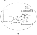
- FIGs. 3 and 4 illustrate a fuel injection control system 200 configured to actively control fuel 72, fuel-air, and flame within the combustor 56 of gas turbine engines 20 in real-time.
- the fuel injection control system 200 includes a charge controller 210 configured to apply a first electrical charge 212 to fuel 72, such that the fuel 72 becomes a charged fuel 72a.
- the charge controller 210 is also configured to apply a second electrical charge 214 to a component 250 of the combustor 56.
- the first electrical charge 212 may be applied to the fuel 72 prior to the fuel 72 reaching the fuel nozzle 78 or the first electrical charge 212 may be applied to the fuel 72 at the fuel nozzle 78.
- the fuel nozzle 78 is configured to spray the charged fuel 72a through the component 250 and into a combustion chamber 54 of the combustor 56.
- the first electrical charge 212 is applied to the fuel 72 at a first frequency and the second electrical charge 214 is applied to the component 250 at a second frequency such that at least one of a selected tone is produced by spraying the charged fuel 72a, a selected screech is produced by spraying the charged fuel 72a, and a selected noise is produced by spraying the charged fuel 72a.
- At least one of the first electrical charge 212 and the second electrical charge 214 at least one of the selected tone produced by spraying the charged fuel 72a, the selected screech produced by spraying the charged fuel 72a, and the selected noise produced by spraying the charged fuel 72a may be controlled and adjusted to help avoid a natural resonance frequency that may damage the combustor 56.
- noise, tone, and screech of the gas turbine engine are a harmonic acoustic environment that can detrimentally affect engine noise levels or the long term well-being of components excited by or near said acoustic environment.
- Noise is the overall acoustic output of the combustor 56.
- a selected noise may be a noise having specific sound characteristics including but not limited to specific values of amplitude, frequency, wavelength, and decibel level of the noise.
- tone noise Combustion instability
- tone noise tonal noise
- the tonal noise which may not only discomfort to people in and around the aircraft, the vibration caused by tone noise, causing damage to the aircraft part including the engine parts.
- a selected tone may be a tone having specific sound characteristics including but not limited to specific values of amplitude, frequency, wavelength, and decibel level of the tone.
- Augmentors or "afterburners” provide an increase in thrust generated by a gas turbine engine 20.
- Fuel 72 is sprayed into a core stream and ignited to produce the desired additional thrust.
- the fuel 72 is fed into the core stream C in the combustor 56.
- Combustor screech results when natural modes of the combustor couple with unsteady heat released by a combustion flame. Uniform heat release perturbation across the duct combines with the natural modes to produce the strongest screech.
- a selected screech may be a screech having specific sound characteristics including but not limited to specific values of amplitude, frequency, wavelength, and decibel level of the screech.
- the polarity of the first electrical charge 212 and the second electrical charge 214 may be adjusted in real-time to adjust at least one of the conical angle ⁇ 1 of the charged fuel 72a, the selected tone produced by spraying the charged fuel 72a, the selected screech produced by spraying the charged fuel 72a, and the selected noise produced by spraying the charged fuel 72a.
- the first electrical charge 212 and the second electrical charge 214 have an opposite charge polarity, such that one electrical charge 212, 214 may be positive and the other electrical charge 212, 214 may be negative. In the example shown in FIG. 4 , the charged fuel 72a is negative and the component 250 is positive, thus the charged fuel 72a that is negatively charged is attracted to the component 250 that is positively charged.
- the polarity of the charged fuel 72a and the component 250 may be changed in real-time.
- the first electrical charge 212 and the second electrical charge 214 have an equivalent charge polarity.
- the first electrical charge 212 and the second electrical charge 214 may be a negative charge, such that the charged fuel 72a that is negatively charged is repelled away from the component 250 that is negatively charged.
- the magnitude of at least one of the first electrical charge 212 and the second electrical charge 214 may be adjusted in real-time to adjust at least one of the conical angle ⁇ 1 of the charged fuel 72a, the selected tone produced by spraying the charged fuel 72a, the selected screech produced by spraying the charged fuel 72a, and the selected noise produced by spraying the charged fuel 72a.
- the component 250 may be a charged ring located within the combustor 250 of the gas turbine engine 20, as shown in FIGs. 3 and 4 .
- the component 250 is a charged ring located within the fuel nozzle 78 of the gas turbine engine 20.
- the component 250 is the fuel nozzle 78.
- the component 250 may be the outer wall 60 and the inner wall 90.
- the component 250 may be the liners 62 and 92 and/or the shells 64 and 94.
- the liners 62 and 92 and/or the shells 64 and 94 may be electrically charged with the second electrical charge 214 to either attract or repel the charged fuel 72a.
- the fuel injection control system 200 also includes an amperage reader 220 that is electrically connected to the component 250 and the charge controller 210.
- an amperage reader 220 that is electrically connected to the component 250 and the charge controller 210.
- the amperage reader 220 is configured to detect a change in amperage of electrical current flow through the component 250 and transmit the change of amperage to the charge controller 210.
- the charge controller 210 is configured to adjust a polarity or magnitude of at least one of the first electrical charge 212 or second electrical charge 214 in response to the amperage detected.
- the utilization of the amperage reader 220 creates a closed-feedback loop, such that real-time updates may be performed for at least one of the conical angle ⁇ 1 of the charged fuel 72a, the selected tone produced by spraying the charged fuel 72a, the selected screech produced by spraying the charged fuel 72a, and the selected noise produced by spraying the charged fuel 72a.
- the gas turbine engine 20 will see improvements to durability and relight ability by actively changing the conical angle ⁇ 1 of the charged fuel 72a in response to the touchdown of fuel on the component 250.
- FIG. 6 illustrates a method 600 of controlling fuel injection into a combustor 56 of a gas turbine engine 20.
- a first electrical charge 212 is applied to fuel 72 such that the fuel 72 becomes a charged fuel 72a.
- a second electrical charge 214 is applied to a component 250 of the combustor 56.
- the charged fuel 72a is sprayed through the component 250 and into a combustion chamber 54 of the combustor 56 from a fuel nozzle 78.
- the first electrical charge 212 is applied to the fuel at a first frequency and the second electrical charge 214 is applied to the component 250 at a second frequency such that at least one of a selected tone is produced by spraying the charged fuel 72a, a selected screech is produced by spraying the charged fuel 72a, and a selected noise is produced by spraying the charged fuel 72a.
- the first frequency and the second frequency may be equivalent.
- the first frequency and the second frequency may not be equivalent.
- at least one of the first frequency and the second frequency may be equal to zero (i.e., no frequency).
- inventions of the present disclosure include applying an electrical charge to fuel and then utilizing charge attractions and/or repulsion to adjust at least one of the conical angle of the charged fuel, the selected tone produced by spraying the charged fuel, the selected screech produced by spraying the charged fuel, and the selected noise produced by spraying the charged fuel.
Landscapes
- Engineering & Computer Science (AREA)
- Chemical & Material Sciences (AREA)
- Combustion & Propulsion (AREA)
- Mechanical Engineering (AREA)
- General Engineering & Computer Science (AREA)
- Chemical Kinetics & Catalysis (AREA)
- Pressure-Spray And Ultrasonic-Wave- Spray Burners (AREA)
Abstract
Description
- The subject matter disclosed herein generally relates to gas turbine engines and, more particularly, to a method and apparatus for fuel injection control in combustors of gas turbine engines.
- A gas turbine engine, typically used as a source of propulsion in aircraft, operates by drawing in ambient air, combusting that air with a fuel, and then forcing the exhaust from the combustion process out of the engine. A fan and compressor section, having a low and high pressure compressor, rotate to draw in and compress the ambient air. The compressed air is then forced into the combustor, where it is split. A portion of the air is used to cool the combustor while the rest is mixed with a fuel and combusted.
- The combustor includes fuel injector, which is a device for dispersing fuel into the combustor to be combusted. The fuel enters a nozzle which atomizes the fuel to allow for greater air-fuel mixing before the combustion process. Conventionally, once the fuel injector is designed and installed, there is little ability to change performance aspects of the fuel injector, such as, for example, fuel spray angle, fuel spray atomization, and fuel spray breadth.
- According to an embodiment, a method of controlling fuel injection into a combustor of a gas turbine engine is provided. The method including: applying a first electrical charge to fuel such that the fuel becomes a charged fuel; and applying a second electrical charge to a component of the combustor, the first electrical charge is applied to the fuel at a first frequency and the second electrical charge is applied to the component at a second frequency such that at least one of a selected tone, a selected screech, and a selected noise is produced by spraying the charged fuel through the component and into a combustion chamber of the combustor from a fuel nozzle.
- In addition to one or more of the features described herein, or as an alternative, further embodiments may include that a polarity or magnitude of at least one of the first electrical charge and the second electrical charge is adjusted to adjust a conical angle of the charged fuel being sprayed by the fuel nozzle.
- In addition to one or more of the features described herein, or as an alternative, further embodiments may include that the first electrical charge and the second electrical charge have an opposite charge polarity.
- In addition to one or more of the features described herein, or as an alternative, further embodiments may include that the first electrical charge and the second electrical charge have an equivalent charge polarity.
- In addition to one or more of the features described herein, or as an alternative, further embodiments may include that the component is a charged ring located within the combustor of the gas turbine engine or within the fuel nozzle of the gas turbine engine.
- In addition to one or more of the features described herein, or as an alternative, further embodiments may include that the component is the fuel nozzle.
- In addition to one or more of the features described herein, or as an alternative, further embodiments may include that the component is an outer wall of the combustor and an inner wall of the combustor.
- According to another embodiment, a fuel injection control system for use in a combustor of a gas turbine engine is provided. The fuel injection control system including: a charge controller configured to apply a first electrical charge to fuel such that the fuel becomes a charged fuel and apply a second electrical charge to a component of the combustor or fuel nozzle; and a fuel nozzle configured to spray the charged fuel through the component and into a combustion chamber of the combustor, the first electrical charge is applied to the fuel at a first frequency and the second electrical charge is applied to the component at a second frequency such that at least one of a selected tone, a selected screech, and a selected noise is produced by spraying the charged fuel through the component and into a combustion chamber of the combustor from the fuel nozzle.
- In addition to one or more of the features described herein, or as an alternative, further embodiments may include that a polarity or a magnitude of at least one of the first electrical charge and the second electrical charge is adjusted to adjust a conical angle of the charged fuel being sprayed by the fuel nozzle.
- In addition to one or more of the features described herein, or as an alternative, further embodiments may include that the first electrical charge and the second electrical charge have an opposite charge polarity.
- In addition to one or more of the features described herein, or as an alternative, further embodiments may include that the first electrical charge and the second electrical charge have an equivalent charge polarity.
- In addition to one or more of the features described herein, or as an alternative, further embodiments may include that the component is a charged ring located within the combustor of the gas turbine engine or within the fuel nozzle of the gas turbine engine.
- In addition to one or more of the features described herein, or as an alternative, further embodiments may include that the component is fuel nozzle.
- In addition to one or more of the features described herein, or as an alternative, further embodiments may include that the component is an outer wall of the combustor and an inner wall of the combustor.
- According to another embodiment, a fuel injection control system for use in a combustor of a gas turbine engine is provided. The fuel injection control system including: a charge controller configured to apply a first electrical charge to fuel such that the fuel becomes a charged fuel and apply a second electrical charge to a component of the combustor; a fuel nozzle configured to spray the charged fuel through the component and into a combustion chamber of the combustor; and an amperage reader electrically connected to the component and the charge controller, the amperage reader is configured to detect a change in amperage of electrical current flowing through the component and transmit the change of amperage to the charge controller, the charge controller is configured to adjust a polarity or a magnitude of at least one of the first electrical charge or second electrical charge in response to the amperage detected.
- In addition to one or more of the features described herein, or as an alternative, further embodiments may include that the electrical change in amperage of electrical current flowing through the component is caused by the charged fuel touching down on the component.
- In addition to one or more of the features described herein, or as an alternative, further embodiments may include that the polarity or magnitude of at least one of the first electrical charge and the second electrical charge is adjusted to adjust a conical angle of the charged fuel being sprayed by the fuel nozzle.
- In addition to one or more of the features described herein, or as an alternative, further embodiments may include that the first electrical charge and the second electrical charge have an opposite charge polarity.
- In addition to one or more of the features described herein, or as an alternative, further embodiments may include that the first electrical charge and the second electrical charge have an equivalent charge polarity.
- In addition to one or more of the features described herein, or as an alternative, further embodiments may include that the component is a charged ring located within the combustor of the gas turbine engine or within the fuel nozzle.
- The foregoing features and elements may be combined in various combinations without exclusivity, unless expressly indicated otherwise. These features and elements as well as the operation thereof will become more apparent in light of the following description and the accompanying drawings. It should be understood, however, that the following description and drawings are intended to be illustrative and explanatory in nature and non-limiting.
- The following descriptions should not be considered limiting in any way. With reference to the accompanying drawings, like elements are numbered alike:
-
FIG. 1 is a partial cross-sectional illustration of a gas turbine engine, in accordance with an embodiment of the disclosure; -
FIG. 2 is a cross-sectional illustration of a combustor for use in the gas turbine engine ofFIG. 1 , in accordance with an embodiment of the disclosure; -
FIG. 3 is a block diagram illustration of a fuel injection control system for use in the combustor ofFIG. 2 , in accordance with an embodiment of the disclosure; -
FIG. 4 is an example of the charge polarity of charged fuel and a charged component for the fuel injection control system ofFIG. 3 , in accordance with an embodiment of the disclosure; -
FIG. 5 is an block diagram illustration of a fuel injection control system for use in the combustor ofFIG. 2 , in accordance with an embodiment of the disclosure; and -
FIG. 6 is an illustration of a method of controlling fuel injection into the combustor ofFIG. 2 , in accordance with an embodiment of the disclosure. - The detailed description explains embodiments of the present disclosure, together with advantages and features, by way of example with reference to the drawings.
- A detailed description of one or more embodiments of the disclosed apparatus and method are presented herein by way of exemplification and not limitation with reference to the Figures.
-
FIG. 1 schematically illustrates agas turbine engine 20. Thegas turbine engine 20 is disclosed herein as a two-spool turbofan that generally incorporates afan section 22, acompressor section 24, acombustor section 26 and aturbine section 28. Alternative engines might include an augmentor section (not shown) among other systems or features. Thefan section 22 drives air along a bypass flow path B in a bypass duct, while thecompressor section 24 drives air along a core flow path C for compression and communication into thecombustor section 26 then expansion through theturbine section 28. Although depicted as a two-spool turbofan gas turbine engine in the disclosed non-limiting embodiment, it should be understood that the concepts described herein are not limited to use with two-spool turbofans as the teachings may be applied to other types of turbine engines including three-spool architectures. - The
exemplary engine 20 generally includes alow speed spool 30 and ahigh speed spool 32 mounted for rotation about an engine central longitudinal axis A relative to an enginestatic structure 36 viaseveral bearing systems 38. It should be understood thatvarious bearing systems 38 at various locations may alternatively or additionally be provided, and the location ofbearing systems 38 may be varied as appropriate to the application. - The
low speed spool 30 generally includes aninner shaft 40 that interconnects afan 42, alow pressure compressor 44 and alow pressure turbine 46. Theinner shaft 40 is connected to thefan 42 through a speed change mechanism, which in exemplarygas turbine engine 20 is illustrated as a gearedarchitecture 48 to drive thefan 42 at a lower speed than thelow speed spool 30. Thehigh speed spool 32 includes anouter shaft 50 that interconnects ahigh pressure compressor 52 andhigh pressure turbine 54. Acombustor 56 is arranged inexemplary gas turbine 20 between thehigh pressure compressor 52 and thehigh pressure turbine 54. An enginestatic structure 36 is arranged generally between thehigh pressure turbine 54 and thelow pressure turbine 46. The enginestatic structure 36 further supports bearingsystems 38 in theturbine section 28. Theinner shaft 40 and theouter shaft 50 are concentric and rotate viabearing systems 38 about the engine central longitudinal axis A which is collinear with their longitudinal axes. - The core airflow is compressed by the
low pressure compressor 44 then thehigh pressure compressor 52, mixed and burned with fuel in thecombustor 56, then expanded over thehigh pressure turbine 54 andlow pressure turbine 46. Theturbines low speed spool 30 andhigh speed spool 32 in response to the expansion. It will be appreciated that each of the positions of thefan section 22,compressor section 24,combustor section 26,turbine section 28, and fandrive gear system 48 may be varied. For example,gear system 48 may be located aft ofcombustor section 26 or even aft ofturbine section 28, andfan section 22 may be positioned forward or aft of the location ofgear system 48. - The
engine 20 in one example is a high-bypass geared aircraft engine. In a further example, theengine 20 bypass ratio is greater than about six (6), with an example embodiment being greater than about ten (10), the gearedarchitecture 48 is an epicyclic gear train, such as a planetary gear system or other gear system, with a gear reduction ratio of greater than about 2.3 and thelow pressure turbine 46 has a pressure ratio that is greater than about five (5). In one disclosed embodiment, theengine 20 bypass ratio is greater than about ten (10:1), the fan diameter is significantly larger than that of thelow pressure compressor 44, and thelow pressure turbine 46 has a pressure ratio that is greater than about five 5:1.Low pressure turbine 46 pressure ratio is pressure measured prior to inlet oflow pressure turbine 46 as related to the pressure at the outlet of thelow pressure turbine 46 prior to an exhaust nozzle. The gearedarchitecture 48 may be an epicycle gear train, such as a planetary gear system or other gear system, with a gear reduction ratio of greater than about 2.3:1. It should be understood, however, that the above parameters are only exemplary of one embodiment of a geared architecture engine and that the present disclosure is applicable to other gas turbine engines including direct drive turbofans. - A significant amount of thrust is provided by the bypass flow B due to the high bypass ratio. The
fan section 22 of theengine 20 is designed for a particular flight condition--typically cruise at about 0.8 Mach and about 35,000 feet (10,688 meters). The flight condition of 0.8 Mach and 35,000 ft (10,688 meters), with the engine at its best fuel consumption--also known as "bucket cruise Thrust Specific Fuel Consumption ('TSFC')"--is the industry standard parameter of lbm of fuel being burned divided by lbf of thrust the engine produces at that minimum point. "Low fan pressure ratio" is the pressure ratio across the fan blade alone, without a Fan Exit Guide Vane ("FEGV") system. The low fan pressure ratio as disclosed herein according to one non-limiting embodiment is less than about 1.45. "Low corrected fan tip speed" is the actual fan tip speed in ft/sec divided by an industry standard temperature correction of [(Tram °R)/(518.7 °R)]05. The "Low corrected fan tip speed" as disclosed herein according to one non-limiting embodiment is less than about 1150 ft/second (350.5 m/sec). - Referring now to
FIG. 2 , thecombustor 56 is depicted as a double-walled annular combustor, centered on the central axis A. However, any form of combustor may be utilized with the present disclosure such as, but not limited to, a single-wall annular combustor or a can combustor. Theannular combustor 56 has anouter wall 60 and aninner wall 90 radially interior to and circumscribed by theouter wall 60. Thewalls annular combustion chamber 54. Theouter wall 60 includes anouter shell 64 and anouter liner 62, while theinner wall 90 includes aninner shell 94 and aninner liner 92. Each of theliners combustion chamber 54 and connected to its associated shell to protect theshells combustion chamber 54. Abulkhead 69 extends from theinner wall 90 to theouter wall 60 at a forward end of the forward section 34 of thecombustor 56 and has aheat shield 66 mounted thereupon to protect thebulkhead 69 from high temperatures in thecombustion chamber 54. Theaft section 36 of thecombustor 56 is open to allow exhaust from the combustion process to exit thecombustor 56 and enter into theturbine section 28. - At least one
fuel injector 78 extends into thecombustion chamber 54 through thebulkhead 69. Aswirler 70 may be generally positioned around thefuel injector 78 such that compressed air may be admitted through theswirler 70 to be mixed with afuel 72 provided by thefuel injector 78. Theswirler 70 may increase the turbulence in the air traveling through theswirler 70, which may increase the mixing of the air andfuel 72. Thefuel injector 78, as shown inFIG. 3 , has amount 74 to secure thefuel injector 78 to theengine 20 and aradial support 76 extending radially inward from themount 72 to anozzle 78, which extends axially through thebulkhead 69 to the combustion chamber. - Conventional ability to control fuel, fuel-air, and flame within the
combustor 56 ofgas turbine engines 20 after the hardware of thecombustor 56 has been installed is very limited, which means relying heavily on analysis and iterative builds up front to meet desired combustion, operability, and durability requirements. This process is expensive and time consuming. Additionally a combustor configuration that improves panel durability often results in decreased relight ability and operability. Relight ability being the ability to restart the combustion process of thegas turbine engine 20 after the combustion process has ceased. Embodiments disclosed herein seek to address the ability to control fuel, fuel-air, and flame within thecombustor 56 ofgas turbine engines 20 after the hardware of thecombustor 56 has been installed. - Referring now to
FIGs. 3-5 with continued reference toFIGs. 1 and2 .FIGs. 3 and4 illustrate a fuelinjection control system 200 configured to actively controlfuel 72, fuel-air, and flame within thecombustor 56 ofgas turbine engines 20 in real-time. As shown inFIG. 3 , the fuelinjection control system 200 includes acharge controller 210 configured to apply a firstelectrical charge 212 tofuel 72, such that thefuel 72 becomes a chargedfuel 72a. Thecharge controller 210 is also configured to apply a secondelectrical charge 214 to acomponent 250 of thecombustor 56. The firstelectrical charge 212 may be applied to thefuel 72 prior to thefuel 72 reaching thefuel nozzle 78 or the firstelectrical charge 212 may be applied to thefuel 72 at thefuel nozzle 78. Thefuel nozzle 78 is configured to spray the chargedfuel 72a through thecomponent 250 and into acombustion chamber 54 of thecombustor 56. In an embodiment, the firstelectrical charge 212 is applied to thefuel 72 at a first frequency and the secondelectrical charge 214 is applied to thecomponent 250 at a second frequency such that at least one of a selected tone is produced by spraying the chargedfuel 72a, a selected screech is produced by spraying the chargedfuel 72a, and a selected noise is produced by spraying the chargedfuel 72a. Advantageously, by changing the at least one of the firstelectrical charge 212 and the secondelectrical charge 214 at least one of the selected tone produced by spraying the chargedfuel 72a, the selected screech produced by spraying the chargedfuel 72a, and the selected noise produced by spraying the chargedfuel 72a may be controlled and adjusted to help avoid a natural resonance frequency that may damage thecombustor 56. - The noise, tone, and screech of the gas turbine engine are a harmonic acoustic environment that can detrimentally affect engine noise levels or the long term well-being of components excited by or near said acoustic environment. Noise is the overall acoustic output of the
combustor 56. A selected noise may be a noise having specific sound characteristics including but not limited to specific values of amplitude, frequency, wavelength, and decibel level of the noise. - Combustion instability is commonly referred to as "tonal noise (tonal noise)". The tonal noise which may not only discomfort to people in and around the aircraft, the vibration caused by tone noise, causing damage to the aircraft part including the engine parts. A selected tone may be a tone having specific sound characteristics including but not limited to specific values of amplitude, frequency, wavelength, and decibel level of the tone.
- Augmentors or "afterburners" provide an increase in thrust generated by a
gas turbine engine 20.Fuel 72 is sprayed into a core stream and ignited to produce the desired additional thrust. Thefuel 72 is fed into the core stream C in thecombustor 56. Combustor screech results when natural modes of the combustor couple with unsteady heat released by a combustion flame. Uniform heat release perturbation across the duct combines with the natural modes to produce the strongest screech. A selected screech may be a screech having specific sound characteristics including but not limited to specific values of amplitude, frequency, wavelength, and decibel level of the screech. - In an embodiment the polarity of the first
electrical charge 212 and the secondelectrical charge 214 may be adjusted in real-time to adjust at least one of the conical angle θ1 of the chargedfuel 72a, the selected tone produced by spraying the chargedfuel 72a, the selected screech produced by spraying the chargedfuel 72a, and the selected noise produced by spraying the chargedfuel 72a. In an embodiment, the firstelectrical charge 212 and the secondelectrical charge 214 have an opposite charge polarity, such that oneelectrical charge electrical charge FIG. 4 , the chargedfuel 72a is negative and thecomponent 250 is positive, thus the chargedfuel 72a that is negatively charged is attracted to thecomponent 250 that is positively charged. In an embodiment, the polarity of the chargedfuel 72a and thecomponent 250 may be changed in real-time. In an embodiment, the firstelectrical charge 212 and the secondelectrical charge 214 have an equivalent charge polarity. In an example, the firstelectrical charge 212 and the secondelectrical charge 214 may be a negative charge, such that the chargedfuel 72a that is negatively charged is repelled away from thecomponent 250 that is negatively charged. Additionally, in another embodiment, the magnitude of at least one of the firstelectrical charge 212 and the secondelectrical charge 214 may be adjusted in real-time to adjust at least one of the conical angle θ1 of the chargedfuel 72a, the selected tone produced by spraying the chargedfuel 72a, the selected screech produced by spraying the chargedfuel 72a, and the selected noise produced by spraying the chargedfuel 72a. - In an embodiment, the
component 250 may be a charged ring located within thecombustor 250 of thegas turbine engine 20, as shown inFIGs. 3 and4 . In another embodiment, thecomponent 250 is a charged ring located within thefuel nozzle 78 of thegas turbine engine 20. In another embodiment, thecomponent 250 is thefuel nozzle 78. In another embodiment, thecomponent 250 may be theouter wall 60 and theinner wall 90. For example, thecomponent 250 may be theliners shells liners shells electrical charge 214 to either attract or repel the chargedfuel 72a. - In the embodiment shown in
FIG. 5 , the fuelinjection control system 200 also includes anamperage reader 220 that is electrically connected to thecomponent 250 and thecharge controller 210. As chargedfuel 72a impacts thecomponent 250, the amperage of electrical current flow through thecomponent 250 will change, which will give charge controller 210 a way to detect how much chargedfuel 72a is touching down on thecomponent 250. The change in electrical current flowing through thecomponent 250 is facilitated by a change in electrical charge created by the touch down ofcharge fuel 72a on a differently chargedcomponent 250. Theamperage reader 220 is configured to detect a change in amperage of electrical current flow through thecomponent 250 and transmit the change of amperage to thecharge controller 210. Thecharge controller 210 is configured to adjust a polarity or magnitude of at least one of the firstelectrical charge 212 or secondelectrical charge 214 in response to the amperage detected. The utilization of theamperage reader 220 creates a closed-feedback loop, such that real-time updates may be performed for at least one of the conical angle θ1 of the chargedfuel 72a, the selected tone produced by spraying the chargedfuel 72a, the selected screech produced by spraying the chargedfuel 72a, and the selected noise produced by spraying the chargedfuel 72a. Advantageously, thegas turbine engine 20 will see improvements to durability and relight ability by actively changing the conical angle θ1 of the chargedfuel 72a in response to the touchdown of fuel on thecomponent 250. - Referring now to
FIG. 6 with continued reference toFIGs. 1-5 .FIG. 6 illustrates amethod 600 of controlling fuel injection into acombustor 56 of agas turbine engine 20. Atblock 604, a firstelectrical charge 212 is applied to fuel 72 such that thefuel 72 becomes a chargedfuel 72a. Atblock 606, a secondelectrical charge 214 is applied to acomponent 250 of thecombustor 56. Atblock 608, the chargedfuel 72a is sprayed through thecomponent 250 and into acombustion chamber 54 of the combustor 56 from afuel nozzle 78. In an embodiment, the firstelectrical charge 212 is applied to the fuel at a first frequency and the secondelectrical charge 214 is applied to thecomponent 250 at a second frequency such that at least one of a selected tone is produced by spraying the chargedfuel 72a, a selected screech is produced by spraying the chargedfuel 72a, and a selected noise is produced by spraying the chargedfuel 72a. In an embodiment, the first frequency and the second frequency may be equivalent. In another embodiment, the first frequency and the second frequency may not be equivalent. In another embodiment, at least one of the first frequency and the second frequency may be equal to zero (i.e., no frequency). - Technical effects of embodiments of the present disclosure include applying an electrical charge to fuel and then utilizing charge attractions and/or repulsion to adjust at least one of the conical angle of the charged fuel, the selected tone produced by spraying the charged fuel, the selected screech produced by spraying the charged fuel, and the selected noise produced by spraying the charged fuel.
- The term "about" is intended to include the degree of error associated with measurement of the particular quantity based upon the equipment available at the time of filing the application. For example, "about" can include a non-limiting range of ± 8% or 5%, or 2% of a given value.
- The terminology used herein is for the purpose of describing particular embodiments only and is not intended to be limiting of the present disclosure. As used herein, the singular forms "a", "an" and "the" are intended to include the plural forms as well, unless the context clearly indicates otherwise. It will be further understood that the terms "comprises" and/or "comprising," when used in this specification, specify the presence of stated features, integers, steps, operations, elements, and/or components, but do not preclude the presence or addition of one or more other features, integers, steps, operations, element components, and/or groups thereof.
- While the present disclosure has been described with reference to an exemplary embodiment or embodiments, it will be understood by those skilled in the art that various changes may be made and equivalents may be substituted for elements thereof without departing from the scope of the present disclosure. In addition, many modifications may be made to adapt a particular situation or material to the teachings of the present disclosure without departing from the scope thereof. Therefore, it is intended that the present disclosure not be limited to the particular embodiment disclosed as the best mode contemplated for carrying out this present disclosure, but that the present disclosure will include all embodiments falling within the scope of the claims.
Claims (15)
- A method (600) of controlling fuel injection into a combustor (56) of a gas turbine engine (20), the method comprising:applying a first electrical charge (212) to fuel (72) such that the fuel becomes a charged fuel (72a); andapplying a second electrical charge (214) to a component (250) of the combustor,wherein the first electrical charge is applied to the fuel at a first frequency and the second electrical charge is applied to the component at a second frequency such that at least one of a selected tone, a selected screech, and a selected noise is produced by spraying the charged fuel through the component and into a combustion chamber (54) of the combustor from a fuel nozzle (78).
- The method (600) of claim 1, wherein a polarity or magnitude of at least one of the first electrical charge (212) and the second electrical charge (214) is adjusted to adjust a conical angle (θ1) of the charged fuel (72a) being sprayed by the fuel nozzle (78).
- The method (600) of claim 1 or 2, wherein the first electrical charge (212) and the second electrical charge (214) have an opposite charge polarity; or wherein the first electrical charge and the second electrical charge have an equivalent charge polarity.
- The method (600) of claim 1, 2 or 3, wherein the component (250) is a charged ring located within the combustor (56) of the gas turbine engine (20) or within the fuel nozzle (78) of the gas turbine engine.
- The method (600) of claim 1, 2 or 3, wherein the component (250) is the fuel nozzle (78); or
wherein the component (250) is an outer wall (60) of the combustor (56) and an inner wall (90) of the combustor (56). - A fuel injection control system (200) for use in a combustor (56) of a gas turbine engine (20), the fuel injection control system comprising:a charge controller (210) configured to apply a first electrical charge (212) to fuel (72) such that the fuel becomes a charged fuel (72a) and apply a second electrical charge (214) to a component (250) of the combustor or fuel nozzle (78); anda fuel nozzle configured to spray the charged fuel through the component and into a combustion chamber (54) of the combustor,wherein the first electrical charge is applied to the fuel at a first frequency and the second electrical charge is applied to the component at a second frequency such that at least one of a selected tone, a selected screech, and a selected noise is produced by spraying the charged fuel through the component and into a combustion chamber of the combustor from the fuel nozzle.
- The fuel injection control system (200) of claim 6, wherein a polarity or a magnitude of at least one of the first electrical charge (212) and the second electrical charge (214) is adjusted to adjust a conical angle (θ1) of the charged fuel (72a) being sprayed by the fuel nozzle (78).
- The fuel injection control system (200) of claim 6 or 7, wherein the first electrical charge (212) and the second electrical charge (214) have an opposite charge polarity; or
wherein the first electrical charge and the second electrical charge have an equivalent charge polarity. - The fuel injection control system (200) of claim 6, 7 or 8, wherein the component (250) is a charged ring located within the combustor (56) of the gas turbine engine (20) or within the fuel nozzle (78) of the gas turbine engine.
- The fuel injection control system (200) of claim 6, 7 or 8, wherein the component (250) is the fuel nozzle (78); or
wherein the component is an outer wall (60) of the combustor and an inner wall (90) of the combustor (56). - A fuel injection control system (200) for use in a combustor (56) of a gas turbine engine (20), the fuel injection control system comprising:a charge controller (210) configured to apply a first electrical charge (212) to fuel (72) such that the fuel becomes a charged fuel (72a) and apply a second electrical charge (214) to a component (250) of the combustor;a fuel nozzle (78) configured to spray the charged fuel through the component and into a combustion chamber (54) of the combustor; andan amperage reader (220) electrically connected to the component and the charge controller, wherein the amperage reader is configured to detect a change in amperage of electrical current flowing through the component and transmit the change of amperage to the charge controller, wherein the charge controller is configured to adjust a polarity or a magnitude of at least one of the first electrical charge or second electrical charge in response to the amperage detected.
- The fuel injection control system (200) of claim 11, wherein the electrical change in amperage of electrical current flowing through the component (250) is caused by the charged fuel (72a) touching down on the component.
- The fuel injection control system (200) of claim 11 or 12, wherein the polarity or magnitude of at least one of the first electrical charge (212) and the second electrical charge (214) is adjusted to adjust a conical angle (θ1) of the charged fuel (72a) being sprayed by the fuel nozzle (78).
- The fuel injection control system (200) of claim 11, 12 or 13, wherein the first electrical charge (212) and the second electrical charge (214) have an opposite charge polarity; or
wherein the first electrical charge and the second electrical charge have an equivalent charge polarity. - The fuel injection control system (200) of any of claims 11 to 14, wherein the component (250) is a charged ring located within the combustor (56) of the gas turbine engine (20) or within the fuel nozzle (78).
Applications Claiming Priority (1)
| Application Number | Priority Date | Filing Date | Title |
|---|---|---|---|
| US16/020,021 US10563626B2 (en) | 2018-06-27 | 2018-06-27 | Electrostatic flame control technology |
Publications (3)
| Publication Number | Publication Date |
|---|---|
| EP3587921A2 true EP3587921A2 (en) | 2020-01-01 |
| EP3587921A3 EP3587921A3 (en) | 2020-02-12 |
| EP3587921B1 EP3587921B1 (en) | 2021-12-08 |
Family
ID=67402789
Family Applications (1)
| Application Number | Title | Priority Date | Filing Date |
|---|---|---|---|
| EP19183017.3A Active EP3587921B1 (en) | 2018-06-27 | 2019-06-27 | Method of controlling fuel injection into a combustor of a gas turbine engine |
Country Status (2)
| Country | Link |
|---|---|
| US (1) | US10563626B2 (en) |
| EP (1) | EP3587921B1 (en) |
Cited By (2)
| Publication number | Priority date | Publication date | Assignee | Title |
|---|---|---|---|---|
| CN112555051A (en) * | 2020-12-04 | 2021-03-26 | 华中科技大学 | Scramjet engine based on lightning arc discharge ignition technology |
| CN113606606A (en) * | 2021-04-14 | 2021-11-05 | 中国航空发动机研究院 | Method for controlling engine by electric field and engine |
Families Citing this family (1)
| Publication number | Priority date | Publication date | Assignee | Title |
|---|---|---|---|---|
| JP2023157148A (en) * | 2022-04-14 | 2023-10-26 | 三菱重工業株式会社 | Fuel supply pipe assembly, gas turbine combustor and gas turbine |
Family Cites Families (8)
| Publication number | Priority date | Publication date | Assignee | Title |
|---|---|---|---|---|
| JPS5596356A (en) * | 1979-01-18 | 1980-07-22 | Nissan Motor Co Ltd | Fuel injector for internal combustion engine |
| DE19942387A1 (en) | 1999-07-14 | 2001-01-18 | Abb Alstom Power Ch Ag | Method for burning a liquid fuel in a combustion system and combustion system for carrying out the method |
| DE60122414T2 (en) | 2000-04-01 | 2006-12-21 | Alstom Technology Ltd. | Combustion system for a gas turbine |
| FR2950545B1 (en) | 2009-09-29 | 2012-11-30 | Centre Nat Rech Scient | DEVICE AND METHOD FOR ELECTROSTATIC PROJECTION OF A LIQUID, FUEL INJECTOR INCORPORATING THIS DEVICE AND USES THEREOF |
| GB201012626D0 (en) * | 2010-07-28 | 2010-09-08 | Rolls Royce Plc | Controllable flameholder |
| US8955325B1 (en) * | 2011-08-31 | 2015-02-17 | The United States Of America, As Represented By The Secretary Of The Navy | Charged atomization of fuel for increased combustion efficiency in jet engines |
| US9151252B2 (en) | 2012-09-28 | 2015-10-06 | General Electric Company | Systems and methods for improved combustion |
| RU2615618C1 (en) | 2015-12-18 | 2017-04-05 | федеральное государственное автономное образовательное учреждение высшего образования "Санкт-Петербургский политехнический университет Петра Великого" (ФГАОУ ВО "СПбПУ") | Fuel jet of gas turbine engine |
-
2018
- 2018-06-27 US US16/020,021 patent/US10563626B2/en active Active
-
2019
- 2019-06-27 EP EP19183017.3A patent/EP3587921B1/en active Active
Cited By (2)
| Publication number | Priority date | Publication date | Assignee | Title |
|---|---|---|---|---|
| CN112555051A (en) * | 2020-12-04 | 2021-03-26 | 华中科技大学 | Scramjet engine based on lightning arc discharge ignition technology |
| CN113606606A (en) * | 2021-04-14 | 2021-11-05 | 中国航空发动机研究院 | Method for controlling engine by electric field and engine |
Also Published As
| Publication number | Publication date |
|---|---|
| US10563626B2 (en) | 2020-02-18 |
| EP3587921B1 (en) | 2021-12-08 |
| US20200003165A1 (en) | 2020-01-02 |
| EP3587921A3 (en) | 2020-02-12 |
Similar Documents
| Publication | Publication Date | Title |
|---|---|---|
| US20220026068A1 (en) | Fuel nozzle for gas turbine engine combustor | |
| CN109312925B (en) | Contoured Cover Swirl Premix Fuel Injector Assembly | |
| CA2771562C (en) | Hybrid slinger combustion system | |
| EP2977680B1 (en) | Dilution hole assembly | |
| US20180283689A1 (en) | Film starters in combustors of gas turbine engines | |
| US12359814B2 (en) | Reducing noise from a combustor of a gas turbine engine | |
| EP3587921B1 (en) | Method of controlling fuel injection into a combustor of a gas turbine engine | |
| US10550704B2 (en) | High performance convergent divergent nozzle | |
| EP3421738B1 (en) | Damper check valve | |
| US11326775B2 (en) | Variable swirl fuel nozzle | |
| US7966823B2 (en) | Exhaust dust flow splitter system | |
| EP3431876B1 (en) | Swirler for combustor of gas turbine engine | |
| US11506382B2 (en) | System and method for acoustic dampers with multiple volumes in a combustion chamber front panel | |
| US11098653B2 (en) | Apparatus and method for mitigating particulate accumulation on a component of a gas turbine | |
| US10590952B2 (en) | Nacelle assembly | |
| US20250092848A1 (en) | Supplemental thrust system with rotating detonation combustor | |
| US11047575B2 (en) | Combustor heat shield panel | |
| US10948189B2 (en) | Enhancement for fuel spray breakup | |
| US20210199296A1 (en) | Combustor liner with shield holes | |
| CN120890098A (en) | Turbine engine combustor with tunable acoustic damper |
Legal Events
| Date | Code | Title | Description |
|---|---|---|---|
| PUAI | Public reference made under article 153(3) epc to a published international application that has entered the european phase |
Free format text: ORIGINAL CODE: 0009012 |
|
| STAA | Information on the status of an ep patent application or granted ep patent |
Free format text: STATUS: THE APPLICATION HAS BEEN PUBLISHED |
|
| AK | Designated contracting states |
Kind code of ref document: A2 Designated state(s): AL AT BE BG CH CY CZ DE DK EE ES FI FR GB GR HR HU IE IS IT LI LT LU LV MC MK MT NL NO PL PT RO RS SE SI SK SM TR |
|
| AX | Request for extension of the european patent |
Extension state: BA ME |
|
| PUAL | Search report despatched |
Free format text: ORIGINAL CODE: 0009013 |
|
| RIC1 | Information provided on ipc code assigned before grant |
Ipc: F23D 11/32 20060101AFI20191217BHEP Ipc: F23C 99/00 20060101ALI20191217BHEP Ipc: F02C 7/22 20060101ALI20191217BHEP Ipc: F23R 3/28 20060101ALI20191217BHEP |
|
| AK | Designated contracting states |
Kind code of ref document: A3 Designated state(s): AL AT BE BG CH CY CZ DE DK EE ES FI FR GB GR HR HU IE IS IT LI LT LU LV MC MK MT NL NO PL PT RO RS SE SI SK SM TR |
|
| AX | Request for extension of the european patent |
Extension state: BA ME |
|
| RIC1 | Information provided on ipc code assigned before grant |
Ipc: F02C 7/22 20060101ALI20200107BHEP Ipc: F23R 3/28 20060101ALI20200107BHEP Ipc: F23C 99/00 20060101ALI20200107BHEP Ipc: F23D 11/32 20060101AFI20200107BHEP |
|
| STAA | Information on the status of an ep patent application or granted ep patent |
Free format text: STATUS: REQUEST FOR EXAMINATION WAS MADE |
|
| 17P | Request for examination filed |
Effective date: 20200812 |
|
| RBV | Designated contracting states (corrected) |
Designated state(s): AL AT BE BG CH CY CZ DE DK EE ES FI FR GB GR HR HU IE IS IT LI LT LU LV MC MK MT NL NO PL PT RO RS SE SI SK SM TR |
|
| RAP1 | Party data changed (applicant data changed or rights of an application transferred) |
Owner name: RAYTHEON TECHNOLOGIES CORPORATION |
|
| GRAP | Despatch of communication of intention to grant a patent |
Free format text: ORIGINAL CODE: EPIDOSNIGR1 |
|
| STAA | Information on the status of an ep patent application or granted ep patent |
Free format text: STATUS: GRANT OF PATENT IS INTENDED |
|
| GRAJ | Information related to disapproval of communication of intention to grant by the applicant or resumption of examination proceedings by the epo deleted |
Free format text: ORIGINAL CODE: EPIDOSDIGR1 |
|
| GRAP | Despatch of communication of intention to grant a patent |
Free format text: ORIGINAL CODE: EPIDOSNIGR1 |
|
| INTG | Intention to grant announced |
Effective date: 20210414 |
|
| GRAJ | Information related to disapproval of communication of intention to grant by the applicant or resumption of examination proceedings by the epo deleted |
Free format text: ORIGINAL CODE: EPIDOSDIGR1 |
|
| GRAP | Despatch of communication of intention to grant a patent |
Free format text: ORIGINAL CODE: EPIDOSNIGR1 |
|
| INTG | Intention to grant announced |
Effective date: 20210426 |
|
| GRAJ | Information related to disapproval of communication of intention to grant by the applicant or resumption of examination proceedings by the epo deleted |
Free format text: ORIGINAL CODE: EPIDOSDIGR1 |
|
| GRAP | Despatch of communication of intention to grant a patent |
Free format text: ORIGINAL CODE: EPIDOSNIGR1 |
|
| INTG | Intention to grant announced |
Effective date: 20210526 |
|
| INTG | Intention to grant announced |
Effective date: 20210617 |
|
| GRAS | Grant fee paid |
Free format text: ORIGINAL CODE: EPIDOSNIGR3 |
|
| GRAA | (expected) grant |
Free format text: ORIGINAL CODE: 0009210 |
|
| STAA | Information on the status of an ep patent application or granted ep patent |
Free format text: STATUS: THE PATENT HAS BEEN GRANTED |
|
| AK | Designated contracting states |
Kind code of ref document: B1 Designated state(s): AL AT BE BG CH CY CZ DE DK EE ES FI FR GB GR HR HU IE IS IT LI LT LU LV MC MK MT NL NO PL PT RO RS SE SI SK SM TR |
|
| REG | Reference to a national code |
Ref country code: GB Ref legal event code: FG4D |
|
| REG | Reference to a national code |
Ref country code: AT Ref legal event code: REF Ref document number: 1454046 Country of ref document: AT Kind code of ref document: T Effective date: 20211215 Ref country code: CH Ref legal event code: EP |
|
| REG | Reference to a national code |
Ref country code: DE Ref legal event code: R096 Ref document number: 602019009830 Country of ref document: DE |
|
| REG | Reference to a national code |
Ref country code: IE Ref legal event code: FG4D |
|
| REG | Reference to a national code |
Ref country code: LT Ref legal event code: MG9D |
|
| REG | Reference to a national code |
Ref country code: NL Ref legal event code: MP Effective date: 20211208 |
|
| PG25 | Lapsed in a contracting state [announced via postgrant information from national office to epo] |
Ref country code: RS Free format text: LAPSE BECAUSE OF FAILURE TO SUBMIT A TRANSLATION OF THE DESCRIPTION OR TO PAY THE FEE WITHIN THE PRESCRIBED TIME-LIMIT Effective date: 20211208 Ref country code: LT Free format text: LAPSE BECAUSE OF FAILURE TO SUBMIT A TRANSLATION OF THE DESCRIPTION OR TO PAY THE FEE WITHIN THE PRESCRIBED TIME-LIMIT Effective date: 20211208 Ref country code: FI Free format text: LAPSE BECAUSE OF FAILURE TO SUBMIT A TRANSLATION OF THE DESCRIPTION OR TO PAY THE FEE WITHIN THE PRESCRIBED TIME-LIMIT Effective date: 20211208 Ref country code: BG Free format text: LAPSE BECAUSE OF FAILURE TO SUBMIT A TRANSLATION OF THE DESCRIPTION OR TO PAY THE FEE WITHIN THE PRESCRIBED TIME-LIMIT Effective date: 20220308 |
|
| REG | Reference to a national code |
Ref country code: AT Ref legal event code: MK05 Ref document number: 1454046 Country of ref document: AT Kind code of ref document: T Effective date: 20211208 |
|
| PG25 | Lapsed in a contracting state [announced via postgrant information from national office to epo] |
Ref country code: SE Free format text: LAPSE BECAUSE OF FAILURE TO SUBMIT A TRANSLATION OF THE DESCRIPTION OR TO PAY THE FEE WITHIN THE PRESCRIBED TIME-LIMIT Effective date: 20211208 Ref country code: NO Free format text: LAPSE BECAUSE OF FAILURE TO SUBMIT A TRANSLATION OF THE DESCRIPTION OR TO PAY THE FEE WITHIN THE PRESCRIBED TIME-LIMIT Effective date: 20220308 Ref country code: LV Free format text: LAPSE BECAUSE OF FAILURE TO SUBMIT A TRANSLATION OF THE DESCRIPTION OR TO PAY THE FEE WITHIN THE PRESCRIBED TIME-LIMIT Effective date: 20211208 Ref country code: HR Free format text: LAPSE BECAUSE OF FAILURE TO SUBMIT A TRANSLATION OF THE DESCRIPTION OR TO PAY THE FEE WITHIN THE PRESCRIBED TIME-LIMIT Effective date: 20211208 Ref country code: GR Free format text: LAPSE BECAUSE OF FAILURE TO SUBMIT A TRANSLATION OF THE DESCRIPTION OR TO PAY THE FEE WITHIN THE PRESCRIBED TIME-LIMIT Effective date: 20220309 Ref country code: ES Free format text: LAPSE BECAUSE OF FAILURE TO SUBMIT A TRANSLATION OF THE DESCRIPTION OR TO PAY THE FEE WITHIN THE PRESCRIBED TIME-LIMIT Effective date: 20211208 |
|
| PG25 | Lapsed in a contracting state [announced via postgrant information from national office to epo] |
Ref country code: NL Free format text: LAPSE BECAUSE OF FAILURE TO SUBMIT A TRANSLATION OF THE DESCRIPTION OR TO PAY THE FEE WITHIN THE PRESCRIBED TIME-LIMIT Effective date: 20211208 |
|
| PG25 | Lapsed in a contracting state [announced via postgrant information from national office to epo] |
Ref country code: SM Free format text: LAPSE BECAUSE OF FAILURE TO SUBMIT A TRANSLATION OF THE DESCRIPTION OR TO PAY THE FEE WITHIN THE PRESCRIBED TIME-LIMIT Effective date: 20211208 Ref country code: SK Free format text: LAPSE BECAUSE OF FAILURE TO SUBMIT A TRANSLATION OF THE DESCRIPTION OR TO PAY THE FEE WITHIN THE PRESCRIBED TIME-LIMIT Effective date: 20211208 Ref country code: RO Free format text: LAPSE BECAUSE OF FAILURE TO SUBMIT A TRANSLATION OF THE DESCRIPTION OR TO PAY THE FEE WITHIN THE PRESCRIBED TIME-LIMIT Effective date: 20211208 Ref country code: PT Free format text: LAPSE BECAUSE OF FAILURE TO SUBMIT A TRANSLATION OF THE DESCRIPTION OR TO PAY THE FEE WITHIN THE PRESCRIBED TIME-LIMIT Effective date: 20220408 Ref country code: EE Free format text: LAPSE BECAUSE OF FAILURE TO SUBMIT A TRANSLATION OF THE DESCRIPTION OR TO PAY THE FEE WITHIN THE PRESCRIBED TIME-LIMIT Effective date: 20211208 Ref country code: CZ Free format text: LAPSE BECAUSE OF FAILURE TO SUBMIT A TRANSLATION OF THE DESCRIPTION OR TO PAY THE FEE WITHIN THE PRESCRIBED TIME-LIMIT Effective date: 20211208 |
|
| PG25 | Lapsed in a contracting state [announced via postgrant information from national office to epo] |
Ref country code: PL Free format text: LAPSE BECAUSE OF FAILURE TO SUBMIT A TRANSLATION OF THE DESCRIPTION OR TO PAY THE FEE WITHIN THE PRESCRIBED TIME-LIMIT Effective date: 20211208 Ref country code: AT Free format text: LAPSE BECAUSE OF FAILURE TO SUBMIT A TRANSLATION OF THE DESCRIPTION OR TO PAY THE FEE WITHIN THE PRESCRIBED TIME-LIMIT Effective date: 20211208 |
|
| REG | Reference to a national code |
Ref country code: DE Ref legal event code: R097 Ref document number: 602019009830 Country of ref document: DE |
|
| PG25 | Lapsed in a contracting state [announced via postgrant information from national office to epo] |
Ref country code: IS Free format text: LAPSE BECAUSE OF FAILURE TO SUBMIT A TRANSLATION OF THE DESCRIPTION OR TO PAY THE FEE WITHIN THE PRESCRIBED TIME-LIMIT Effective date: 20220408 |
|
| PLBE | No opposition filed within time limit |
Free format text: ORIGINAL CODE: 0009261 |
|
| STAA | Information on the status of an ep patent application or granted ep patent |
Free format text: STATUS: NO OPPOSITION FILED WITHIN TIME LIMIT |
|
| PG25 | Lapsed in a contracting state [announced via postgrant information from national office to epo] |
Ref country code: DK Free format text: LAPSE BECAUSE OF FAILURE TO SUBMIT A TRANSLATION OF THE DESCRIPTION OR TO PAY THE FEE WITHIN THE PRESCRIBED TIME-LIMIT Effective date: 20211208 Ref country code: AL Free format text: LAPSE BECAUSE OF FAILURE TO SUBMIT A TRANSLATION OF THE DESCRIPTION OR TO PAY THE FEE WITHIN THE PRESCRIBED TIME-LIMIT Effective date: 20211208 |
|
| 26N | No opposition filed |
Effective date: 20220909 |
|
| PG25 | Lapsed in a contracting state [announced via postgrant information from national office to epo] |
Ref country code: SI Free format text: LAPSE BECAUSE OF FAILURE TO SUBMIT A TRANSLATION OF THE DESCRIPTION OR TO PAY THE FEE WITHIN THE PRESCRIBED TIME-LIMIT Effective date: 20211208 |
|
| PG25 | Lapsed in a contracting state [announced via postgrant information from national office to epo] |
Ref country code: MC Free format text: LAPSE BECAUSE OF FAILURE TO SUBMIT A TRANSLATION OF THE DESCRIPTION OR TO PAY THE FEE WITHIN THE PRESCRIBED TIME-LIMIT Effective date: 20211208 |
|
| REG | Reference to a national code |
Ref country code: CH Ref legal event code: PL |
|
| REG | Reference to a national code |
Ref country code: BE Ref legal event code: MM Effective date: 20220630 |
|
| PG25 | Lapsed in a contracting state [announced via postgrant information from national office to epo] |
Ref country code: LU Free format text: LAPSE BECAUSE OF NON-PAYMENT OF DUE FEES Effective date: 20220627 Ref country code: LI Free format text: LAPSE BECAUSE OF NON-PAYMENT OF DUE FEES Effective date: 20220630 Ref country code: IE Free format text: LAPSE BECAUSE OF NON-PAYMENT OF DUE FEES Effective date: 20220627 Ref country code: CH Free format text: LAPSE BECAUSE OF NON-PAYMENT OF DUE FEES Effective date: 20220630 |
|
| PG25 | Lapsed in a contracting state [announced via postgrant information from national office to epo] |
Ref country code: IT Free format text: LAPSE BECAUSE OF FAILURE TO SUBMIT A TRANSLATION OF THE DESCRIPTION OR TO PAY THE FEE WITHIN THE PRESCRIBED TIME-LIMIT Effective date: 20211208 Ref country code: BE Free format text: LAPSE BECAUSE OF NON-PAYMENT OF DUE FEES Effective date: 20220630 |
|
| P01 | Opt-out of the competence of the unified patent court (upc) registered |
Effective date: 20230521 |
|
| PG25 | Lapsed in a contracting state [announced via postgrant information from national office to epo] |
Ref country code: MK Free format text: LAPSE BECAUSE OF FAILURE TO SUBMIT A TRANSLATION OF THE DESCRIPTION OR TO PAY THE FEE WITHIN THE PRESCRIBED TIME-LIMIT Effective date: 20211208 Ref country code: CY Free format text: LAPSE BECAUSE OF FAILURE TO SUBMIT A TRANSLATION OF THE DESCRIPTION OR TO PAY THE FEE WITHIN THE PRESCRIBED TIME-LIMIT Effective date: 20211208 |
|
| PG25 | Lapsed in a contracting state [announced via postgrant information from national office to epo] |
Ref country code: HU Free format text: LAPSE BECAUSE OF FAILURE TO SUBMIT A TRANSLATION OF THE DESCRIPTION OR TO PAY THE FEE WITHIN THE PRESCRIBED TIME-LIMIT; INVALID AB INITIO Effective date: 20190627 |
|
| PG25 | Lapsed in a contracting state [announced via postgrant information from national office to epo] |
Ref country code: MT Free format text: LAPSE BECAUSE OF FAILURE TO SUBMIT A TRANSLATION OF THE DESCRIPTION OR TO PAY THE FEE WITHIN THE PRESCRIBED TIME-LIMIT Effective date: 20211208 |
|
| PGFP | Annual fee paid to national office [announced via postgrant information from national office to epo] |
Ref country code: DE Payment date: 20250520 Year of fee payment: 7 |
|
| PGFP | Annual fee paid to national office [announced via postgrant information from national office to epo] |
Ref country code: GB Payment date: 20250520 Year of fee payment: 7 |
|
| PGFP | Annual fee paid to national office [announced via postgrant information from national office to epo] |
Ref country code: FR Payment date: 20250521 Year of fee payment: 7 |
|
| REG | Reference to a national code |
Ref country code: DE Ref legal event code: R081 Ref document number: 602019009830 Country of ref document: DE Owner name: RTX CORPORATION (N.D.GES.D. STAATES DELAWARE),, US Free format text: FORMER OWNER: RAYTHEON TECHNOLOGIES CORPORATION, FARMINGTON, CT, US |
|
| PG25 | Lapsed in a contracting state [announced via postgrant information from national office to epo] |
Ref country code: TR Free format text: LAPSE BECAUSE OF FAILURE TO SUBMIT A TRANSLATION OF THE DESCRIPTION OR TO PAY THE FEE WITHIN THE PRESCRIBED TIME-LIMIT Effective date: 20211208 |