EP3587860B1 - Integral torque limiter differential - Google Patents
Integral torque limiter differential Download PDFInfo
- Publication number
- EP3587860B1 EP3587860B1 EP19164234.7A EP19164234A EP3587860B1 EP 3587860 B1 EP3587860 B1 EP 3587860B1 EP 19164234 A EP19164234 A EP 19164234A EP 3587860 B1 EP3587860 B1 EP 3587860B1
- Authority
- EP
- European Patent Office
- Prior art keywords
- housing
- shaft
- differential
- disposed
- brake
- Prior art date
- Legal status (The legal status is an assumption and is not a legal conclusion. Google has not performed a legal analysis and makes no representation as to the accuracy of the status listed.)
- Active
Links
Images



Classifications
-
- F—MECHANICAL ENGINEERING; LIGHTING; HEATING; WEAPONS; BLASTING
- F16—ENGINEERING ELEMENTS AND UNITS; GENERAL MEASURES FOR PRODUCING AND MAINTAINING EFFECTIVE FUNCTIONING OF MACHINES OR INSTALLATIONS; THERMAL INSULATION IN GENERAL
- F16D—COUPLINGS FOR TRANSMITTING ROTATION; CLUTCHES; BRAKES
- F16D59/00—Self-acting brakes, e.g. coming into operation at a predetermined speed
-
- B—PERFORMING OPERATIONS; TRANSPORTING
- B60—VEHICLES IN GENERAL
- B60T—VEHICLE BRAKE CONTROL SYSTEMS OR PARTS THEREOF; BRAKE CONTROL SYSTEMS OR PARTS THEREOF, IN GENERAL; ARRANGEMENT OF BRAKING ELEMENTS ON VEHICLES IN GENERAL; PORTABLE DEVICES FOR PREVENTING UNWANTED MOVEMENT OF VEHICLES; VEHICLE MODIFICATIONS TO FACILITATE COOLING OF BRAKES
- B60T1/00—Arrangements of braking elements, i.e. of those parts where braking effect occurs specially for vehicles
- B60T1/02—Arrangements of braking elements, i.e. of those parts where braking effect occurs specially for vehicles acting by retarding wheels
- B60T1/06—Arrangements of braking elements, i.e. of those parts where braking effect occurs specially for vehicles acting by retarding wheels acting otherwise than on tread, e.g. employing rim, drum, disc, or transmission or on double wheels
- B60T1/062—Arrangements of braking elements, i.e. of those parts where braking effect occurs specially for vehicles acting by retarding wheels acting otherwise than on tread, e.g. employing rim, drum, disc, or transmission or on double wheels acting on transmission parts
-
- B—PERFORMING OPERATIONS; TRANSPORTING
- B60—VEHICLES IN GENERAL
- B60T—VEHICLE BRAKE CONTROL SYSTEMS OR PARTS THEREOF; BRAKE CONTROL SYSTEMS OR PARTS THEREOF, IN GENERAL; ARRANGEMENT OF BRAKING ELEMENTS ON VEHICLES IN GENERAL; PORTABLE DEVICES FOR PREVENTING UNWANTED MOVEMENT OF VEHICLES; VEHICLE MODIFICATIONS TO FACILITATE COOLING OF BRAKES
- B60T7/00—Brake-action initiating means
- B60T7/12—Brake-action initiating means for automatic initiation; for initiation not subject to will of driver or passenger
-
- F—MECHANICAL ENGINEERING; LIGHTING; HEATING; WEAPONS; BLASTING
- F16—ENGINEERING ELEMENTS AND UNITS; GENERAL MEASURES FOR PRODUCING AND MAINTAINING EFFECTIVE FUNCTIONING OF MACHINES OR INSTALLATIONS; THERMAL INSULATION IN GENERAL
- F16H—GEARING
- F16H3/00—Toothed gearings for conveying rotary motion with variable gear ratio or for reversing rotary motion
- F16H3/44—Toothed gearings for conveying rotary motion with variable gear ratio or for reversing rotary motion using gears having orbital motion
- F16H3/72—Toothed gearings for conveying rotary motion with variable gear ratio or for reversing rotary motion using gears having orbital motion with a secondary drive, e.g. regulating motor, in order to vary speed continuously
-
- F—MECHANICAL ENGINEERING; LIGHTING; HEATING; WEAPONS; BLASTING
- F16—ENGINEERING ELEMENTS AND UNITS; GENERAL MEASURES FOR PRODUCING AND MAINTAINING EFFECTIVE FUNCTIONING OF MACHINES OR INSTALLATIONS; THERMAL INSULATION IN GENERAL
- F16H—GEARING
- F16H35/00—Gearings or mechanisms with other special functional features
- F16H35/10—Arrangements or devices for absorbing overload or preventing damage by overload
-
- F—MECHANICAL ENGINEERING; LIGHTING; HEATING; WEAPONS; BLASTING
- F16—ENGINEERING ELEMENTS AND UNITS; GENERAL MEASURES FOR PRODUCING AND MAINTAINING EFFECTIVE FUNCTIONING OF MACHINES OR INSTALLATIONS; THERMAL INSULATION IN GENERAL
- F16H—GEARING
- F16H37/00—Combinations of mechanical gearings, not provided for in groups F16H1/00 - F16H35/00
- F16H37/02—Combinations of mechanical gearings, not provided for in groups F16H1/00 - F16H35/00 comprising essentially only toothed or friction gearings
- F16H37/06—Combinations of mechanical gearings, not provided for in groups F16H1/00 - F16H35/00 comprising essentially only toothed or friction gearings with a plurality of driving or driven shafts; with arrangements for dividing torque between two or more intermediate shafts
- F16H37/08—Combinations of mechanical gearings, not provided for in groups F16H1/00 - F16H35/00 comprising essentially only toothed or friction gearings with a plurality of driving or driven shafts; with arrangements for dividing torque between two or more intermediate shafts with differential gearing
- F16H37/0806—Combinations of mechanical gearings, not provided for in groups F16H1/00 - F16H35/00 comprising essentially only toothed or friction gearings with a plurality of driving or driven shafts; with arrangements for dividing torque between two or more intermediate shafts with differential gearing with a plurality of driving or driven shafts
- F16H37/0826—Combinations of mechanical gearings, not provided for in groups F16H1/00 - F16H35/00 comprising essentially only toothed or friction gearings with a plurality of driving or driven shafts; with arrangements for dividing torque between two or more intermediate shafts with differential gearing with a plurality of driving or driven shafts with only one output shaft
-
- F—MECHANICAL ENGINEERING; LIGHTING; HEATING; WEAPONS; BLASTING
- F16—ENGINEERING ELEMENTS AND UNITS; GENERAL MEASURES FOR PRODUCING AND MAINTAINING EFFECTIVE FUNCTIONING OF MACHINES OR INSTALLATIONS; THERMAL INSULATION IN GENERAL
- F16H—GEARING
- F16H48/00—Differential gearings
- F16H48/06—Differential gearings with gears having orbital motion
- F16H48/08—Differential gearings with gears having orbital motion comprising bevel gears
-
- F—MECHANICAL ENGINEERING; LIGHTING; HEATING; WEAPONS; BLASTING
- F16—ENGINEERING ELEMENTS AND UNITS; GENERAL MEASURES FOR PRODUCING AND MAINTAINING EFFECTIVE FUNCTIONING OF MACHINES OR INSTALLATIONS; THERMAL INSULATION IN GENERAL
- F16H—GEARING
- F16H48/00—Differential gearings
- F16H48/38—Constructional details
- F16H48/42—Constructional details characterised by features of the input shafts, e.g. mounting of drive gears thereon
-
- F—MECHANICAL ENGINEERING; LIGHTING; HEATING; WEAPONS; BLASTING
- F16—ENGINEERING ELEMENTS AND UNITS; GENERAL MEASURES FOR PRODUCING AND MAINTAINING EFFECTIVE FUNCTIONING OF MACHINES OR INSTALLATIONS; THERMAL INSULATION IN GENERAL
- F16D—COUPLINGS FOR TRANSMITTING ROTATION; CLUTCHES; BRAKES
- F16D2125/00—Components of actuators
- F16D2125/18—Mechanical mechanisms
- F16D2125/58—Mechanical mechanisms transmitting linear movement
- F16D2125/582—Flexible element, e.g. spring, other than the main force generating element
-
- F—MECHANICAL ENGINEERING; LIGHTING; HEATING; WEAPONS; BLASTING
- F16—ENGINEERING ELEMENTS AND UNITS; GENERAL MEASURES FOR PRODUCING AND MAINTAINING EFFECTIVE FUNCTIONING OF MACHINES OR INSTALLATIONS; THERMAL INSULATION IN GENERAL
- F16D—COUPLINGS FOR TRANSMITTING ROTATION; CLUTCHES; BRAKES
- F16D2127/00—Auxiliary mechanisms
- F16D2127/001—Auxiliary mechanisms for automatic or self-acting brake operation
- F16D2127/005—Auxiliary mechanisms for automatic or self-acting brake operation force- or torque-responsive
-
- F—MECHANICAL ENGINEERING; LIGHTING; HEATING; WEAPONS; BLASTING
- F16—ENGINEERING ELEMENTS AND UNITS; GENERAL MEASURES FOR PRODUCING AND MAINTAINING EFFECTIVE FUNCTIONING OF MACHINES OR INSTALLATIONS; THERMAL INSULATION IN GENERAL
- F16D—COUPLINGS FOR TRANSMITTING ROTATION; CLUTCHES; BRAKES
- F16D55/00—Brakes with substantially-radial braking surfaces pressed together in axial direction, e.g. disc brakes
- F16D55/24—Brakes with substantially-radial braking surfaces pressed together in axial direction, e.g. disc brakes with a plurality of axially-movable discs, lamellae, or pads, pressed from one side towards an axially-located member
- F16D55/26—Brakes with substantially-radial braking surfaces pressed together in axial direction, e.g. disc brakes with a plurality of axially-movable discs, lamellae, or pads, pressed from one side towards an axially-located member without self-tightening action
- F16D55/36—Brakes with a plurality of rotating discs all lying side by side
-
- F—MECHANICAL ENGINEERING; LIGHTING; HEATING; WEAPONS; BLASTING
- F16—ENGINEERING ELEMENTS AND UNITS; GENERAL MEASURES FOR PRODUCING AND MAINTAINING EFFECTIVE FUNCTIONING OF MACHINES OR INSTALLATIONS; THERMAL INSULATION IN GENERAL
- F16H—GEARING
- F16H48/00—Differential gearings
- F16H48/06—Differential gearings with gears having orbital motion
- F16H48/08—Differential gearings with gears having orbital motion comprising bevel gears
- F16H2048/082—Differential gearings with gears having orbital motion comprising bevel gears characterised by the arrangement of output shafts
-
- F—MECHANICAL ENGINEERING; LIGHTING; HEATING; WEAPONS; BLASTING
- F16—ENGINEERING ELEMENTS AND UNITS; GENERAL MEASURES FOR PRODUCING AND MAINTAINING EFFECTIVE FUNCTIONING OF MACHINES OR INSTALLATIONS; THERMAL INSULATION IN GENERAL
- F16H—GEARING
- F16H57/00—General details of gearing
- F16H57/0018—Shaft assemblies for gearings
- F16H57/0025—Shaft assemblies for gearings with gearing elements rigidly connected to a shaft, e.g. securing gears or pulleys by specially adapted splines, keys or methods
Definitions
- Exemplary embodiments pertain to the art of differentials having torque limiters.
- a power drive unit includes gear trains possibly having a differential.
- the power drive unit provides a mechanical output to an output member, such as an aircraft control surface or other device requiring rotary power input from a power source.
- the differential may be provided with a torque limiter that is arranged to limit an output torque to inhibit or reduce the transmission of torque by the output member.
- EP 2 054 299 relates to a jam-tolerant actuator.
- EP 1 342 603 relates to a hybrid transmission.
- WO 2010/039403 relates to a method and system for limiting blade pitch.
- US 2010/285917 A1 relates to a differential assembly according to the preamble of claim 1.
- a differential assembly that includes a housing assembly, an output shaft, a shaft, a differential unit, and a torque limiter.
- the housing assembly is disposed about a first axis and has a first housing and a second housing. The first housing and the second housing defining a cavity therebetween.
- the output shaft extends at least partially through at least one of the first housing and the second housing along the first axis.
- the shaft is disposed about and is arranged to translate along the first axis relative to the output shaft.
- the differential unit is disposed within the cavity and is connected to at least one of the output shaft and the shaft.
- the torque limiter is disposed about the output shaft and a portion of the shaft. The torque limiter is arranged to selectively engage a stop wall of at least one of the first housing and the second housing to inhibit rotation of the output shaft about the first axis.
- a power drive unit 10 includes a gear train having a differential assembly 12.
- the power drive unit 10 may receive power inputs from a first power input 20 and a second power input 22, such as motors that are combined or run individually through the differential assembly 12 and delivered to an output device, control device, a reduction gear assembly or gear, or the like through an output shaft 24.
- the first power input 20 and the second power input 22 are independent/redundant power inputs, where one is sufficient for functionality.
- the output shaft 24 may be an output shaft assembly having a first output shaft and a second output shaft that are coupled to each other through a differential unit.
- the differential assembly 12 includes the output shaft 24, a housing assembly 30, a first carrier or a first shaft 32, a first input member 34, a second input member 35, a differential unit 36, and a torque limiter 38.
- the differential assembly 12 may be arranged to include a single brake torque limiter, as shown in FIG. 1 , or a dual brake torque limiter, as shown in FIGS. 2 , 3 , and 4 .
- the housing assembly 30 is disposed about a first axis 40.
- the housing assembly 30 includes a first housing 44 that extends between a first housing first end portion 46 and a first housing second end portion 48 along the first axis 40.
- the housing assembly 30 further includes a second housing 50 that extends between a second housing first end portion 52 and a second housing second end portion 54 along the first axis 40.
- the first housing 44 defines a brake bore 60, a biasing member bore 62, a first bearing bore 64, and a second bearing bore 66.
- the brake bore 60 extends from the first housing first end portion 46 towards a stop wall 70.
- the stop wall 70 is disposed between the brake bore 60 and the biasing member bore 62.
- the stop wall 70 may be defined by a portion of the first housing first end portion 46 that extends between the first bearing bore 64 and the brake bore 60.
- the brake bore 60 may have a brake bore diameter.
- the biasing member bore 62 extends from the stop wall 70 towards an end wall 72 defined by the first housing second end portion 48.
- the biasing member bore 62 may have a biasing member bore diameter that is less than the brake bore diameter.
- the biasing member bore 62 may have a biasing member bore diameter that is greater than or substantially equal to the brake bore diameter.
- the first bearing bore 64 may be defined by the first housing first end portion 46.
- the first bearing bore 64 is arranged such that the brake bore 60 is disposed between the first bearing bore 64 and the biasing member bore 62.
- the first bearing bore 64 may have a first bearing bore diameter.
- the second bearing bore 66 may be defined by the first housing second end portion 48.
- the second bearing bore 66 is arranged such that the biasing member bore 62 is disposed between the brake bore 60 and the second bearing bore 66.
- the second bearing bore 66 may have a second bearing bore diameter that is less than the first bearing bore diameter.
- the second bearing bore 66 may have a second bearing bore diameter that is greater than or substantially equal to the first bearing bore diameter.
- the second housing 50 is spaced apart from the first housing 44.
- the second housing 50 defines a first bore 80 and a second bore 82.
- the first bore 80 extends from the second housing first end portion 52 towards the second housing second end portion 54.
- the first bore 80 may have a first bore diameter.
- the second bore 82 extends towards the second housing second end portion 54.
- the second bore 82 may have a second bore diameter that is less than the first bore diameter.
- the second bore 82 may have a second bore diameter that is greater than or substantially equal to the first bore diameter.
- the second housing 50 may have a substantially similar configuration as the first housing 44.
- the features of the second housing 50 may be similar features as to the first housing 44 but mirrored about an axis of symmetry that is disposed transverse to the first axis 40 and extends through a center of the differential unit 36.
- the first bore 60 may be a brake bore
- the second bore 62 may be a biasing member bore
- the end wall 70 may be a stop wall.
- the first housing 44 and the second housing 50 define a cavity 90 that is disposed between the first housing first end portion 46 and the second housing first end portion 52.
- the differential unit 36 is disposed within the cavity 90.
- the first housing 44 may be connected to the second housing 50 through the differential unit 36 or an outer housing.
- the output shaft 24 extends at least partially through the first housing 44, the second housing 50, and the differential unit 36 along the first axis 40.
- the output shaft 24 is rotatably supported by bearings that are disposed within the first housing 44, the second housing 50, and the differential unit 36.
- the first carrier or first shaft 32 is disposed about a first portion of the output shaft 24.
- the first shaft 32 extends between and is at least partially received within the differential unit 36 and the first housing 44.
- the first shaft 32 is arranged to translate along the first axis 40 relative to the first portion of the output shaft 24.
- the first shaft 32 extends between a first shaft first end 100 and a first shaft second end 102.
- the first shaft first end 100 is connected to the differential unit 36.
- the first shaft second end 102 is connected to the torque limiter 38.
- the first shaft second end 102 defines or includes a shaft flange 104 that engages a portion of the torque limiter 38.
- the first shaft 32 is drivably connected to the output shaft 24 through a spline or ball spline provided by a splined portion 106 that is disposed between the first shaft first end 100 and the first shaft second end 102.
- a second shaft 33 is disposed about a second portion of the output shaft 24 and may extend between and may be at least partially received within differential unit 36 and the second housing 50.
- the second shaft 33 may have a substantially similar configuration as the first shaft 32 and may be arranged to translate along the first axis 40 relative to the second portion of the output shaft 24.
- the first input member 34 may be a rotary input member that extends between portions of the first housing 44 and the differential unit 36.
- the first input member 34 is drivably connected to the first shaft 32 through a splined connection 110.
- the first input member 34 is drivably connected to the first power input 20 through a spur gear or the like.
- the first input member 34 transmits a torque that is applied by the first power input 20 to the first shaft 32, to the differential unit 36, and to the output shaft 24.
- the first shaft 32 may move relative to the output shaft 24 along the first axis 40, responsive to a load input through the first input member 34.
- the second input member 35 may be a rotary input member that extends between portions of the second housing 50 and the differential unit 36.
- the second input member 35 may be drivably connected to the second shaft 33.
- the second input member 35 is drivably connected to the second power input 22 through a spur gear or the like.
- the second input member 35 transmits a torque that is applied by the second power input 22 to the second shaft 33, to the differential unit 36, and to the output shaft 24, separately or independently from the input provided by the first input member 34.
- the second shaft 33 may move relative to the output shaft 24 along the first axis 40, responsive to a load input through the second input member 35.
- the differential unit 36 is disposed within the cavity 90 that is defined between the first housing 44 and the second housing 50.
- the differential unit 36 is operatively connected to at least one of the output shaft 24, the first shaft 32, and/or the second shaft.
- the differential unit 36 includes differential gears 114 that are operatively connected to the first shaft 32 and/or the second shaft.
- the differential gears 114 are bevel gears having a lash, mesh, or contact pattern that are varied or adjusted by loading applied by the first input member 34 and/or the torque limiter 38.
- the differential gears 114 rotate around an axis 92.
- the torque limiter 38 is disposed within the first housing 44, as shown in FIG. 1 .
- a first torque limiter is disposed within the first housing 44 and a second torque limiter is disposed within the second housing 50, as shown in FIGS. 2 and 3 .
- the torque limiter(s) 38 is disposed about the output shaft 24 and a portion of the first shaft 32 and/or the second shaft.
- the torque limiter 38 disposed within the first housing 44 will be described, however, the torque limiter disposed within the second housing 50 may have a substantially similar configuration as the torque limiter 38 disposed within the first housing 44.
- the torque limiter 38 is operatively connected to the first shaft 32 and may be spaced apart from the output shaft 24.
- the torque limiter 38 is arranged to selectively inhibit rotation of at least one of the output shaft 24 and/or the first shaft 32 through the selective engagement with the first housing 44, in the embodiment shown in FIG. 1 , or through selective engagement with at least one of the first housing 44 and/or the second housing 50, in the embodiment shown in FIGS. 2 and 3 .
- the torque limiter 38 includes a brake member 120, a biasing member 122, and a bearing member 124.
- the brake member 120 is disposed about the first shaft second end 102 and is disposed proximate the shaft flange 104 of the first shaft 32.
- the brake member 120 is operatively connected to the first shaft 32.
- the brake member 120 is disposed within the brake bore 60 and is arranged to selectively engage the stop wall 70.
- the brake member 120 includes a plurality of brake plates having biasing members disposed between adj acent brake plates.
- the plurality of brake plates may be connected to the first shaft 32 through a splined connection.
- the biasing member 122 is disposed within the biasing member bore 62.
- the biasing member 122 extends between and is operatively connected to the shaft flange 104 through the bearing member 124 and the end wall 72.
- the biasing member 122 is arranged to bias the brake member 120 away from engagement with the stop wall 70.
- the biasing member 122 is arranged to adjust a lash, mesh, or contact pattern between differential gears of the differential unit 36.
- the bearing member 124 is disposed between the brake member 120 and the biasing member 122.
- the bearing member 124 is operatively connected to the shaft flange 104 and an end of the biasing member 122.
- the bearing member 124 may be a thrust bearing or the like.
- the torque limiter 38 is actuated responsive to a load applied to the first shaft 32 by the first input member 34 greater than a threshold load or torque load, which may lead to the separation of the differential gears of the differential unit and overcome the biasing force applied by the biasing member 122.
- the first shaft 32 translates relative to the output shaft 24 and/or the first axis 40, compressing the biasing member 122, and moving the brake member 120 towards engagement with the stop wall 70 of the first housing 44 and/or the second housing 50 to apply a braking effect to reduce a rotational speed and/or inhibit rotation of the output shaft 24, as shown in the top half of FIG. 3 .
- the inhibiting of rotation of the output shaft 24 inhibits the power driving unit 10 from providing a mechanical output to inhibit affected components downstream of the power drive unit 10.
- the differential assembly 200 includes the output shaft 24, a housing assembly 210, a first shaft 212, a first input member 214, a second input member 215, a differential unit 216, and a torque limiter 218.
- the differential assembly 200 may be arranged to include a dual brake or dual torque limiter.
- the housing assembly 210 is disposed about the first axis 40.
- the housing assembly 210 includes a first housing 220 that extends between a first housing first end portion 222 and a first housing second end portion 224 along the first axis 40.
- the housing assembly 210 further includes a second housing 230 that extends between a second housing first end portion 232 and a second housing second end portion 234 along the first axis 40.
- the first housing 220 defines a brake bore 240, a stop wall 242, a first bearing bore 244, and a second bearing bore 246.
- the brake bore 240 extends between the first housing first end portion 222 and the first housing second end portion 224.
- the stop wall 242 is disposed proximate the first housing second end portion 224 and the brake bore 240 terminates at the stop wall 242.
- the first bearing bore 244 may be defined by the first housing first end portion 222.
- the first bearing bore 244 is arranged such that the brake bore 240 is disposed between the first bearing bore 244 and the second bearing bore 246.
- the first bearing bore 244 may have a first bearing bore diameter.
- the second bearing bore 246 may be defined by the first housing second end portion 224.
- the second bearing bore 246 may have a second bearing bore diameter that is less than the first bearing bore diameter.
- the second housing 230 is spaced apart from the first housing 220.
- the second housing 230 defines a brake bore 250, a stop wall 252, a first bearing bore 254, and a second bearing bore 256.
- the brake bore 250 extends between the second housing first end portion 232 and the second housing second end portion 234.
- the stop wall 252 is disposed proximate the second housing second end portion 234 and the brake bore 250 terminates at the stop wall 252.
- the first bearing bore 254 may be defined by the second housing first end portion 232.
- the first bearing bore 254 is arranged such that the brake bore 250 is disposed between the first bearing bore 254 and the second bearing bore 256.
- the first bearing bore 254 may have a first bearing bore diameter.
- the second bearing bore 256 may be defined by the second housing second end portion 234.
- the second bearing bore 256 may have a second bearing bore diameter that is less than the first bearing bore diameter.
- the differential unit 216 is disposed within a cavity 260 that is disposed between the first housing first end portion 222 and the second housing first end portion 232.
- the first housing 220 may be connected to the second housing 230 through the differential unit 216.
- the output shaft 24 extends at least partially through the first housing 220, the second housing 230, and the differential unit 216 along the first axis 40.
- the first shaft 212 is disposed about a first portion of the output shaft 24.
- the first shaft 212 extends between and is at least partially received within the differential unit 216 and the first housing 220.
- the first shaft 212 is arranged to translate along the first axis 40 relative to the first portion of the output shaft 24.
- the first shaft 212 extends between a first shaft first end 270 and a first shaft second end 272.
- the first shaft first end 270 is connected to the differential unit 216.
- the first shaft second end 272 is connected to the torque limiter 218.
- the first shaft 212 is drivably connected to the output shaft 24 through a spline or ball spline provided by a splined portion 276 that is disposed between the first shaft first end 270 and the first shaft second end 272.
- a second shaft 213 is disposed about a second portion of the output shaft 24 and may extend between and may be at least partially received within differential unit 216 and the second housing 230.
- the second shaft 213 may have a substantially similar configuration as the first shaft 212 and may be arranged to translate along the first axis 40 relative to the second portion of the output shaft 24.
- the second shaft 213 may be drivably connected to the output shaft 24 through a spline or ball spline provided by a splined portion 282 that is disposed between a second shaft first end and a second shaft second end.
- the first input member 214 may be a rotary input member that extends between portions of the first housing 220 and the differential unit 216.
- the first input member 214 may be drivably connected to the first shaft 212 through a splined connection 280.
- the first input member 214 is drivably connected to the first power input 20 through a spur gear or the like.
- the first input member 214 transmits a torque that is applied by the first power input 20 to the first shaft 212, to the differential unit 216, and to the output shaft 24.
- the first shaft 212 may move relative to the output shaft 24 along the first axis 40, responsive to a load input through the first input member 214.
- the second input member 215 may be a rotary input member that extends between portions of the second housing 230 and the differential unit 216.
- the second input member 215 may be drivably connected to the second shaft 213 through a splined connection 280.
- the second input member 215 is drivably connected to the second power input 22 through a spur gear or the like.
- the second input member 215 transmits a torque that is applied by the second power input 22 to the second shaft 213, to the differential unit 216, and to the output shaft 24 separately or independently from the input provided by the first input member 214.
- the second shaft 213 may move relative to the output shaft 24 along the first axis 40, responsive to a load input through the second input member 215.
- the differential unit 216 is disposed within the cavity 260 that is defined between the first housing 220 and the second housing 230.
- the differential unit 216 is operatively connected to at least one of the output shaft 24, the first shaft 212, and/or the second shaft 213.
- the differential unit may be configured as an open differential, a locking differential, a limited slip differential, etc.
- the differential unit 216 includes a differential housing 290, a first bearing bore 292, a second bearing bore 294, a carrier 296, and differential gears 298.
- the differential housing 290 defines a differential cavity 300 that extends between a differential housing first end 302 and a differential housing second end 304.
- the first shaft first end 270 and the second shaft first end extend into the differential cavity 300.
- the first bearing bore 292 is defined by the differential housing first end 302.
- the second bearing bore 294 is defined by the differential housing second end 304.
- the carrier 296 is disposed within the differential cavity 300.
- the carrier 296 includes a carrier body 310 having a first carrier arm 312 extending from a first end of the carrier body 310 and a second carrier arm 314 extending from a second end of the carrier body 310.
- the first carrier arm 312 and the second carrier arm 314 each extend towards the first axis 40 and the output shaft 24.
- the differential gears 298 are disposed within the differential cavity 300.
- the differential gears 298 are operatively connected to the first shaft 212 and the second shaft 213.
- the differential gears 298 may be bevel gears having a lash, mesh, or contact pattern that may be varied or adjusted by loading applied by the first input member 214 and/or the torque limiter 218.
- the torque limiter 218 is arranged to selectively inhibit rotation of at least one of the output shaft 24, the first shaft 212, and/or the second shaft 213 through selective engagement with at least one of the first housing 220 and/or the second housing 230.
- the torque limiter 218 includes a first brake member 320, a first biasing member 322, a second brake member 324, and a second biasing member 326.
- the first brake member 320 is disposed about the first shaft second end 272.
- the first brake member 320 may be operatively connected to the first shaft 212.
- the first brake member 320 is disposed within the brake bore 240 and is arranged to selectively engage the stop wall 242.
- the first brake member 320 includes a plurality of brake plates having biasing members disposed between adjacent brake plates.
- the plurality of brake plates may be connected to the first shaft 212 through a splined connection.
- the first biasing member 322 is disposed within the differential cavity 300 of the differential housing 290.
- the first biasing member 322 extends between and is operatively connected to the first carrier arm 312 and at least one of the differential gears 298 and/or the first shaft 212.
- the first biasing member 322 is arranged to bias the first brake member 320 away from engagement with the stop wall 242.
- the first biasing member 322 may be arranged to adjust a lash, mesh, or contact pattern between differential gears 298.
- the first biasing member 322 may include coil springs or a stack of Belleville springs that have a center on a differential gear centerline.
- the second brake member 324 is disposed about the second shaft second end of the second shaft 213.
- the second brake member 324 may be operatively connected to the second shaft 213.
- the second brake member 324 is disposed within the brake bore 250 and is arranged to selectively engage the stop wall 252.
- the second brake member 324 includes a plurality of brake plates having biasing members disposed between adj acent brake plates.
- the plurality of brake plates may be connected to the second shaft 213 through a splined connection.
- the second biasing member 326 is disposed within the differential cavity 300.
- the second biasing member 326 extends between and is operatively connected to the second carrier arm 314 and at least one of the differential gears 298 and/or the second shaft 213.
- the second biasing member 326 is arranged to bias the second brake member 324 away from engagement with the stop wall 252.
- the second biasing member 326 may be arranged to adjust a lash, mesh, or contact pattern between differential gears 298.
- the second biasing member 326 may include coil springs or a stack of Belleville springs that have a center on a differential gear centerline.
- the torque limiter 218 is actuated responsive to a load applied to at least one of the first shaft 212 and/or the second shaft 213 by an input member greater than a threshold load or torque load may lead to the differential gears 298 of the differential unit 216 to separate and overcome the biasing force applied by the biasing members 322, 326.
- the first shaft 212 and/or the second shaft 213 translates relative to the output shaft 24 and/or the first axis 40, compressing the first biasing member 322 and moving the first brake member 320 towards engagement with the stop wall 242 of the first housing 220, compressing the second biasing member 326 and moving the second brake member 324 towards engagement with the stop wall 252 of the second housing 230 to apply a braking effect to reduce a rotational speed and/or inhibit rotation of the output shaft 24, as shown in the bottom half of FIG. 5 .
Landscapes
- Engineering & Computer Science (AREA)
- General Engineering & Computer Science (AREA)
- Mechanical Engineering (AREA)
- Transportation (AREA)
- Retarders (AREA)
Description
- Exemplary embodiments pertain to the art of differentials having torque limiters.
- A power drive unit includes gear trains possibly having a differential. The power drive unit provides a mechanical output to an output member, such as an aircraft control surface or other device requiring rotary power input from a power source. The differential may be provided with a torque limiter that is arranged to limit an output torque to inhibit or reduce the transmission of torque by the output member.
EP 2 054 299EP 1 342 603 relates to a hybrid transmission.WO 2010/039403 relates to a method and system for limiting blade pitch.US 2010/285917 A1 relates to a differential assembly according to the preamble of claim 1. - Disclosed is a differential assembly that includes a housing assembly, an output shaft, a shaft, a differential unit, and a torque limiter. The housing assembly is disposed about a first axis and has a first housing and a second housing. The first housing and the second housing defining a cavity therebetween. The output shaft extends at least partially through at least one of the first housing and the second housing along the first axis. The shaft is disposed about and is arranged to translate along the first axis relative to the output shaft. The differential unit is disposed within the cavity and is connected to at least one of the output shaft and the shaft. The torque limiter is disposed about the output shaft and a portion of the shaft. The torque limiter is arranged to selectively engage a stop wall of at least one of the first housing and the second housing to inhibit rotation of the output shaft about the first axis.
- [deleted]
- The following descriptions should not be considered limiting in any way. With reference to the accompanying drawings, like elements are numbered alike:
-
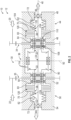
FIG. 1 is a schematic illustration of a first embodiment of a differential assembly having a single brake in a first position; -
FIG. 2 is a schematic illustration of a second embodiment of a differential assembly having dual brakes in a first position; -
FIG. 3 is a schematic illustration of a split view of the second embodiment of the differential assembly in a second position; -
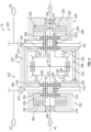
FIG. 4 is a schematic illustration of a not claimed example of a differential assembly having a carrier spring in a first position; and -
FIG. 5 is a schematic illustration of a split view of the not claimed example of the differential assembly in a second position. - A detailed description of one or more embodiments of the disclosed apparatus are presented herein by way of exemplification and not limitation with reference to the Figures.
- Referring to the Figures, a
power drive unit 10 includes a gear train having adifferential assembly 12. Thepower drive unit 10 may receive power inputs from afirst power input 20 and asecond power input 22, such as motors that are combined or run individually through thedifferential assembly 12 and delivered to an output device, control device, a reduction gear assembly or gear, or the like through anoutput shaft 24. Thefirst power input 20 and thesecond power input 22 are independent/redundant power inputs, where one is sufficient for functionality. Theoutput shaft 24 may be an output shaft assembly having a first output shaft and a second output shaft that are coupled to each other through a differential unit. - The
differential assembly 12 includes theoutput shaft 24, ahousing assembly 30, a first carrier or afirst shaft 32, afirst input member 34, asecond input member 35, adifferential unit 36, and atorque limiter 38. Thedifferential assembly 12 may be arranged to include a single brake torque limiter, as shown inFIG. 1 , or a dual brake torque limiter, as shown inFIGS. 2 ,3 , and4 . - Referring to
FIGS. 1 and2 , thehousing assembly 30 is disposed about afirst axis 40. Thehousing assembly 30 includes afirst housing 44 that extends between a first housingfirst end portion 46 and a first housingsecond end portion 48 along thefirst axis 40. Thehousing assembly 30 further includes asecond housing 50 that extends between a second housingfirst end portion 52 and a second housingsecond end portion 54 along thefirst axis 40. - The
first housing 44 defines abrake bore 60, a biasing member bore 62, afirst bearing bore 64, and a second bearing bore 66. - The
brake bore 60 extends from the first housingfirst end portion 46 towards astop wall 70. Thestop wall 70 is disposed between thebrake bore 60 and the biasing member bore 62. In at least one embodiment, thestop wall 70 may be defined by a portion of the first housingfirst end portion 46 that extends between thefirst bearing bore 64 and the brake bore 60. Thebrake bore 60 may have a brake bore diameter. - The
biasing member bore 62 extends from thestop wall 70 towards anend wall 72 defined by the first housingsecond end portion 48. In the embodiment shown, the biasing member bore 62 may have a biasing member bore diameter that is less than the brake bore diameter. In other embodiments, the biasing member bore 62 may have a biasing member bore diameter that is greater than or substantially equal to the brake bore diameter. - The
first bearing bore 64 may be defined by the first housingfirst end portion 46. Thefirst bearing bore 64 is arranged such that thebrake bore 60 is disposed between thefirst bearing bore 64 and the biasing member bore 62. Thefirst bearing bore 64 may have a first bearing bore diameter. - The
second bearing bore 66 may be defined by the first housingsecond end portion 48. Thesecond bearing bore 66 is arranged such that thebiasing member bore 62 is disposed between thebrake bore 60 and thesecond bearing bore 66. In the embodiment shown, thesecond bearing bore 66 may have a second bearing bore diameter that is less than the first bearing bore diameter. In other embodiments, thesecond bearing bore 66 may have a second bearing bore diameter that is greater than or substantially equal to the first bearing bore diameter. - The
second housing 50 is spaced apart from thefirst housing 44. Thesecond housing 50 defines afirst bore 80 and asecond bore 82. Thefirst bore 80 extends from the second housingfirst end portion 52 towards the second housingsecond end portion 54. Thefirst bore 80 may have a first bore diameter. Thesecond bore 82 extends towards the second housingsecond end portion 54. In the embodiment shown, thesecond bore 82 may have a second bore diameter that is less than the first bore diameter. In other embodiments, thesecond bore 82 may have a second bore diameter that is greater than or substantially equal to the first bore diameter. - In the embodiment shown in
FIGS. 2 and3 , thesecond housing 50 may have a substantially similar configuration as thefirst housing 44. In such an arrangement, the features of thesecond housing 50 may be similar features as to thefirst housing 44 but mirrored about an axis of symmetry that is disposed transverse to thefirst axis 40 and extends through a center of thedifferential unit 36. In this arrangement, thefirst bore 60 may be a brake bore, thesecond bore 62 may be a biasing member bore, and theend wall 70 may be a stop wall. - Referring to
FIGS. 1-3 , thefirst housing 44 and thesecond housing 50 define acavity 90 that is disposed between the first housingfirst end portion 46 and the second housingfirst end portion 52. Thedifferential unit 36 is disposed within thecavity 90. Thefirst housing 44 may be connected to thesecond housing 50 through thedifferential unit 36 or an outer housing. - The
output shaft 24 extends at least partially through thefirst housing 44, thesecond housing 50, and thedifferential unit 36 along thefirst axis 40. Theoutput shaft 24 is rotatably supported by bearings that are disposed within thefirst housing 44, thesecond housing 50, and thedifferential unit 36. - The first carrier or
first shaft 32 is disposed about a first portion of theoutput shaft 24. Thefirst shaft 32 extends between and is at least partially received within thedifferential unit 36 and thefirst housing 44. Thefirst shaft 32 is arranged to translate along thefirst axis 40 relative to the first portion of theoutput shaft 24. - The
first shaft 32 extends between a first shaftfirst end 100 and a first shaftsecond end 102. The first shaftfirst end 100 is connected to thedifferential unit 36. The first shaftsecond end 102 is connected to thetorque limiter 38. The first shaftsecond end 102 defines or includes ashaft flange 104 that engages a portion of thetorque limiter 38. - The
first shaft 32 is drivably connected to theoutput shaft 24 through a spline or ball spline provided by asplined portion 106 that is disposed between the first shaftfirst end 100 and the first shaftsecond end 102. - In the embodiment shown in
FIGS. 2 and3 , asecond shaft 33 is disposed about a second portion of theoutput shaft 24 and may extend between and may be at least partially received withindifferential unit 36 and thesecond housing 50. Thesecond shaft 33 may have a substantially similar configuration as thefirst shaft 32 and may be arranged to translate along thefirst axis 40 relative to the second portion of theoutput shaft 24. - The
first input member 34 may be a rotary input member that extends between portions of thefirst housing 44 and thedifferential unit 36. Thefirst input member 34 is drivably connected to thefirst shaft 32 through asplined connection 110. Thefirst input member 34 is drivably connected to thefirst power input 20 through a spur gear or the like. Thefirst input member 34 transmits a torque that is applied by thefirst power input 20 to thefirst shaft 32, to thedifferential unit 36, and to theoutput shaft 24. Thefirst shaft 32 may move relative to theoutput shaft 24 along thefirst axis 40, responsive to a load input through thefirst input member 34. - The
second input member 35 may be a rotary input member that extends between portions of thesecond housing 50 and thedifferential unit 36. Thesecond input member 35 may be drivably connected to thesecond shaft 33. Thesecond input member 35 is drivably connected to thesecond power input 22 through a spur gear or the like. Thesecond input member 35 transmits a torque that is applied by thesecond power input 22 to thesecond shaft 33, to thedifferential unit 36, and to theoutput shaft 24, separately or independently from the input provided by thefirst input member 34. Thesecond shaft 33 may move relative to theoutput shaft 24 along thefirst axis 40, responsive to a load input through thesecond input member 35. - The
differential unit 36 is disposed within thecavity 90 that is defined between thefirst housing 44 and thesecond housing 50. Thedifferential unit 36 is operatively connected to at least one of theoutput shaft 24, thefirst shaft 32, and/or the second shaft. - The
differential unit 36 includesdifferential gears 114 that are operatively connected to thefirst shaft 32 and/or the second shaft. The differential gears 114 are bevel gears having a lash, mesh, or contact pattern that are varied or adjusted by loading applied by thefirst input member 34 and/or thetorque limiter 38. The differential gears 114 rotate around anaxis 92. - The
torque limiter 38 is disposed within thefirst housing 44, as shown inFIG. 1 . A first torque limiter is disposed within thefirst housing 44 and a second torque limiter is disposed within thesecond housing 50, as shown inFIGS. 2 and3 . - The torque limiter(s) 38 is disposed about the
output shaft 24 and a portion of thefirst shaft 32 and/or the second shaft. For brevity, thetorque limiter 38 disposed within thefirst housing 44 will be described, however, the torque limiter disposed within thesecond housing 50 may have a substantially similar configuration as thetorque limiter 38 disposed within thefirst housing 44. - The
torque limiter 38 is operatively connected to thefirst shaft 32 and may be spaced apart from theoutput shaft 24. Thetorque limiter 38 is arranged to selectively inhibit rotation of at least one of theoutput shaft 24 and/or thefirst shaft 32 through the selective engagement with thefirst housing 44, in the embodiment shown inFIG. 1 , or through selective engagement with at least one of thefirst housing 44 and/or thesecond housing 50, in the embodiment shown inFIGS. 2 and3 . - The
torque limiter 38 includes abrake member 120, a biasingmember 122, and a bearingmember 124. - The
brake member 120 is disposed about the first shaftsecond end 102 and is disposed proximate theshaft flange 104 of thefirst shaft 32. Thebrake member 120 is operatively connected to thefirst shaft 32. Thebrake member 120 is disposed within the brake bore 60 and is arranged to selectively engage thestop wall 70. - The
brake member 120 includes a plurality of brake plates having biasing members disposed between adj acent brake plates. The plurality of brake plates may be connected to thefirst shaft 32 through a splined connection. - The biasing
member 122 is disposed within the biasing member bore 62. The biasingmember 122 extends between and is operatively connected to theshaft flange 104 through the bearingmember 124 and theend wall 72. The biasingmember 122 is arranged to bias thebrake member 120 away from engagement with thestop wall 70. The biasingmember 122 is arranged to adjust a lash, mesh, or contact pattern between differential gears of thedifferential unit 36. - The bearing
member 124 is disposed between thebrake member 120 and the biasingmember 122. The bearingmember 124 is operatively connected to theshaft flange 104 and an end of the biasingmember 122. The bearingmember 124 may be a thrust bearing or the like. - The
torque limiter 38 is actuated responsive to a load applied to thefirst shaft 32 by thefirst input member 34 greater than a threshold load or torque load, which may lead to the separation of the differential gears of the differential unit and overcome the biasing force applied by the biasingmember 122. Thefirst shaft 32 translates relative to theoutput shaft 24 and/or thefirst axis 40, compressing the biasingmember 122, and moving thebrake member 120 towards engagement with thestop wall 70 of thefirst housing 44 and/or thesecond housing 50 to apply a braking effect to reduce a rotational speed and/or inhibit rotation of theoutput shaft 24, as shown in the top half ofFIG. 3 . - The inhibiting of rotation of the
output shaft 24 inhibits thepower driving unit 10 from providing a mechanical output to inhibit affected components downstream of thepower drive unit 10. - Referring to
FIGS. 4 and5 , a not claimeddifferential assembly 200 is shown. Thedifferential assembly 200 includes theoutput shaft 24, ahousing assembly 210, afirst shaft 212, afirst input member 214, asecond input member 215, adifferential unit 216, and atorque limiter 218. Thedifferential assembly 200 may be arranged to include a dual brake or dual torque limiter. - The
housing assembly 210 is disposed about thefirst axis 40. Thehousing assembly 210 includes afirst housing 220 that extends between a first housingfirst end portion 222 and a first housingsecond end portion 224 along thefirst axis 40. Thehousing assembly 210 further includes asecond housing 230 that extends between a second housingfirst end portion 232 and a second housingsecond end portion 234 along thefirst axis 40. - The
first housing 220 defines abrake bore 240, astop wall 242, a first bearing bore 244, and a second bearing bore 246. The brake bore 240 extends between the first housingfirst end portion 222 and the first housingsecond end portion 224. Thestop wall 242 is disposed proximate the first housingsecond end portion 224 and the brake bore 240 terminates at thestop wall 242. - The first bearing bore 244 may be defined by the first housing
first end portion 222. The first bearing bore 244 is arranged such that the brake bore 240 is disposed between the first bearing bore 244 and the second bearing bore 246. The first bearing bore 244 may have a first bearing bore diameter. - The second bearing bore 246 may be defined by the first housing
second end portion 224. The second bearing bore 246 may have a second bearing bore diameter that is less than the first bearing bore diameter. - The
second housing 230 is spaced apart from thefirst housing 220. Thesecond housing 230 defines abrake bore 250, astop wall 252, a first bearing bore 254, and a second bearing bore 256. The brake bore 250 extends between the second housingfirst end portion 232 and the second housingsecond end portion 234. Thestop wall 252 is disposed proximate the second housingsecond end portion 234 and the brake bore 250 terminates at thestop wall 252. - The first bearing bore 254 may be defined by the second housing
first end portion 232. The first bearing bore 254 is arranged such that the brake bore 250 is disposed between the first bearing bore 254 and the second bearing bore 256. The first bearing bore 254 may have a first bearing bore diameter. - The second bearing bore 256 may be defined by the second housing
second end portion 234. The second bearing bore 256 may have a second bearing bore diameter that is less than the first bearing bore diameter. - The
differential unit 216 is disposed within acavity 260 that is disposed between the first housingfirst end portion 222 and the second housingfirst end portion 232. Thefirst housing 220 may be connected to thesecond housing 230 through thedifferential unit 216. - The
output shaft 24 extends at least partially through thefirst housing 220, thesecond housing 230, and thedifferential unit 216 along thefirst axis 40. - The
first shaft 212 is disposed about a first portion of theoutput shaft 24. Thefirst shaft 212 extends between and is at least partially received within thedifferential unit 216 and thefirst housing 220. Thefirst shaft 212 is arranged to translate along thefirst axis 40 relative to the first portion of theoutput shaft 24. - The
first shaft 212 extends between a first shaftfirst end 270 and a first shaftsecond end 272. The first shaftfirst end 270 is connected to thedifferential unit 216. The first shaftsecond end 272 is connected to thetorque limiter 218. - The
first shaft 212 is drivably connected to theoutput shaft 24 through a spline or ball spline provided by asplined portion 276 that is disposed between the first shaftfirst end 270 and the first shaftsecond end 272. - A
second shaft 213 is disposed about a second portion of theoutput shaft 24 and may extend between and may be at least partially received withindifferential unit 216 and thesecond housing 230. Thesecond shaft 213 may have a substantially similar configuration as thefirst shaft 212 and may be arranged to translate along thefirst axis 40 relative to the second portion of theoutput shaft 24. Thesecond shaft 213 may be drivably connected to theoutput shaft 24 through a spline or ball spline provided by a splined portion 282 that is disposed between a second shaft first end and a second shaft second end. - The
first input member 214 may be a rotary input member that extends between portions of thefirst housing 220 and thedifferential unit 216. Thefirst input member 214 may be drivably connected to thefirst shaft 212 through asplined connection 280. Thefirst input member 214 is drivably connected to thefirst power input 20 through a spur gear or the like. Thefirst input member 214 transmits a torque that is applied by thefirst power input 20 to thefirst shaft 212, to thedifferential unit 216, and to theoutput shaft 24. Thefirst shaft 212 may move relative to theoutput shaft 24 along thefirst axis 40, responsive to a load input through thefirst input member 214. - The
second input member 215 may be a rotary input member that extends between portions of thesecond housing 230 and thedifferential unit 216. Thesecond input member 215 may be drivably connected to thesecond shaft 213 through asplined connection 280. Thesecond input member 215 is drivably connected to thesecond power input 22 through a spur gear or the like. Thesecond input member 215 transmits a torque that is applied by thesecond power input 22 to thesecond shaft 213, to thedifferential unit 216, and to theoutput shaft 24 separately or independently from the input provided by thefirst input member 214. Thesecond shaft 213 may move relative to theoutput shaft 24 along thefirst axis 40, responsive to a load input through thesecond input member 215. - The
differential unit 216 is disposed within thecavity 260 that is defined between thefirst housing 220 and thesecond housing 230. Thedifferential unit 216 is operatively connected to at least one of theoutput shaft 24, thefirst shaft 212, and/or thesecond shaft 213. The differential unit may be configured as an open differential, a locking differential, a limited slip differential, etc. - The
differential unit 216 includes adifferential housing 290, a first bearing bore 292, a second bearing bore 294, acarrier 296, anddifferential gears 298. - The
differential housing 290 defines adifferential cavity 300 that extends between a differential housingfirst end 302 and a differential housingsecond end 304. The first shaftfirst end 270 and the second shaft first end extend into thedifferential cavity 300. - The first bearing bore 292 is defined by the differential housing
first end 302. The second bearing bore 294 is defined by the differential housingsecond end 304. - The
carrier 296 is disposed within thedifferential cavity 300. Thecarrier 296 includes acarrier body 310 having afirst carrier arm 312 extending from a first end of thecarrier body 310 and asecond carrier arm 314 extending from a second end of thecarrier body 310. Thefirst carrier arm 312 and thesecond carrier arm 314 each extend towards thefirst axis 40 and theoutput shaft 24. - The differential gears 298 are disposed within the
differential cavity 300. The differential gears 298 are operatively connected to thefirst shaft 212 and thesecond shaft 213. The differential gears 298 may be bevel gears having a lash, mesh, or contact pattern that may be varied or adjusted by loading applied by thefirst input member 214 and/or thetorque limiter 218. - The
torque limiter 218 is arranged to selectively inhibit rotation of at least one of theoutput shaft 24, thefirst shaft 212, and/or thesecond shaft 213 through selective engagement with at least one of thefirst housing 220 and/or thesecond housing 230. Thetorque limiter 218 includes afirst brake member 320, afirst biasing member 322, asecond brake member 324, and asecond biasing member 326. - The
first brake member 320 is disposed about the first shaftsecond end 272. Thefirst brake member 320 may be operatively connected to thefirst shaft 212. Thefirst brake member 320 is disposed within the brake bore 240 and is arranged to selectively engage thestop wall 242. - The
first brake member 320 includes a plurality of brake plates having biasing members disposed between adjacent brake plates. The plurality of brake plates may be connected to thefirst shaft 212 through a splined connection. - The
first biasing member 322 is disposed within thedifferential cavity 300 of thedifferential housing 290. Thefirst biasing member 322 extends between and is operatively connected to thefirst carrier arm 312 and at least one of thedifferential gears 298 and/or thefirst shaft 212. Thefirst biasing member 322 is arranged to bias thefirst brake member 320 away from engagement with thestop wall 242. Thefirst biasing member 322 may be arranged to adjust a lash, mesh, or contact pattern between differential gears 298. Thefirst biasing member 322 may include coil springs or a stack of Belleville springs that have a center on a differential gear centerline. - The
second brake member 324 is disposed about the second shaft second end of thesecond shaft 213. Thesecond brake member 324 may be operatively connected to thesecond shaft 213. Thesecond brake member 324 is disposed within the brake bore 250 and is arranged to selectively engage thestop wall 252. - The
second brake member 324 includes a plurality of brake plates having biasing members disposed between adj acent brake plates. The plurality of brake plates may be connected to thesecond shaft 213 through a splined connection. - The
second biasing member 326 is disposed within thedifferential cavity 300. Thesecond biasing member 326 extends between and is operatively connected to thesecond carrier arm 314 and at least one of thedifferential gears 298 and/or thesecond shaft 213. Thesecond biasing member 326 is arranged to bias thesecond brake member 324 away from engagement with thestop wall 252. Thesecond biasing member 326 may be arranged to adjust a lash, mesh, or contact pattern between differential gears 298. Thesecond biasing member 326 may include coil springs or a stack of Belleville springs that have a center on a differential gear centerline. - The
torque limiter 218 is actuated responsive to a load applied to at least one of thefirst shaft 212 and/or thesecond shaft 213 by an input member greater than a threshold load or torque load may lead to thedifferential gears 298 of thedifferential unit 216 to separate and overcome the biasing force applied by the biasingmembers first shaft 212 and/or thesecond shaft 213 translates relative to theoutput shaft 24 and/or thefirst axis 40, compressing thefirst biasing member 322 and moving thefirst brake member 320 towards engagement with thestop wall 242 of thefirst housing 220, compressing thesecond biasing member 326 and moving thesecond brake member 324 towards engagement with thestop wall 252 of thesecond housing 230 to apply a braking effect to reduce a rotational speed and/or inhibit rotation of theoutput shaft 24, as shown in the bottom half ofFIG. 5 . - While the present invention has been described with reference to exemplary embodiments, it will be understood by those skilled in the art that various changes may be made for elements thereof without departing from the scope of the appended claims. Therefore, it is intended that the present invention not be limited to the particular embodiment disclosed as the best mode contemplated for carrying out this present invention, but that the present invention will include all embodiments falling within the scope of the appended claims.
Claims (5)
- A differential assembly (12), comprising:a housing assembly (30) disposed about a first axis (40), the housing assembly (30) having a first housing and a second housing, the first housing (44) and the second housing (50) defining a cavity therebetween;an output shaft (24) that extends at least partially through at least one of the first housing (44) and the second housing (50) along the first axis (40);a first shaft (32) disposed about and arranged to translate along the first axis (40) relative to the output shaft (24);a differential unit (36) disposed within the cavity and connected to at least one of the output shaft (24) and the first shaft (32), wherein the differential unit (36) includes a carrier that is disposed within a differential housing that is connected to the first housing and the second housing;a first input member (34) that is drivably connected to the first shaft (32) through a splined connection defined between the first input member (34) and the first shaft (32);a torque limiter (38) disposed about the output shaft (24) and a portion of the shaft (32),the torque limiter (38) being arranged to selectively engage a stop wall (70) of at least one of the first housing (44) and the second housing (50) to inhibit rotation of the output shaft (24) about the first axis (40),wherein the first shaft (32) extends between a first shaft first end (100) that is connected to the differential unit (36) and a first shaft second end (102) that is connected to the torque limiter (38);wherein the torque limiter (38) includes:a brake member (120) that is disposed about the first shaft second end (102) and disposed within a brake bore (60) defined by at least one of the first housing (44) and the second housing (50);characterised in that the torque limiter further includes:a biasing member (122) that is operatively connected to at least one of the first housing (44) and the second housing (50) and extends towards the brake member (120) and;a bearing member (124) disposed between the brake member (120) and the biasing member (122);wherein the torque limiter (38) is actuated responsive to a load applied to the first shaft (32) by the first input member (34) being greater than a threshold and causes separation of differential gears (114) of differential gear unit (36) to overcome a biasing force applied by the biasing member (122), wherein the first shaft (32) translates relative to the output shaft (24) to compress the biasing member (122) and to move the brake member (120) toward engagement with a stop wall of the first housing (44) and/or the second housing (50), wherein the differential gears (114) are operatively connected to the first shaft (32) and the output shaft (24), and wherein the differential gears (114) are bevel gears having a lash, mesh, or contact pattern that is varied or adjusted by loading applied by the first input member (34) and the torque limiter (38).
- The differential assembly of claim 1, wherein the first shaft second end (102) engages the bearing member (124).
- The differential assembly of claim 1, wherein at least one of the first housing (44) and the second housing (50) defines a biasing member bore that extends from the stop wall (70) towards an end wall (72).
- The differential assembly of claim 3, wherein the biasing member (122) is disposed within the biasing member bore and extends between and engages the end wall and the bearing member (124).
- The differential assembly of claim 3, wherein the biasing member (122) is arranged to bias the brake member (120) away from engagement with the stop wall (70).
Applications Claiming Priority (1)
| Application Number | Priority Date | Filing Date | Title |
|---|---|---|---|
| US15/941,538 US10683903B2 (en) | 2018-03-30 | 2018-03-30 | Integral torque limiter differential |
Publications (2)
| Publication Number | Publication Date |
|---|---|
| EP3587860A1 EP3587860A1 (en) | 2020-01-01 |
| EP3587860B1 true EP3587860B1 (en) | 2023-05-31 |
Family
ID=65904151
Family Applications (1)
| Application Number | Title | Priority Date | Filing Date |
|---|---|---|---|
| EP19164234.7A Active EP3587860B1 (en) | 2018-03-30 | 2019-03-21 | Integral torque limiter differential |
Country Status (2)
| Country | Link |
|---|---|
| US (2) | US10683903B2 (en) |
| EP (1) | EP3587860B1 (en) |
Families Citing this family (3)
| Publication number | Priority date | Publication date | Assignee | Title |
|---|---|---|---|---|
| US10683903B2 (en) | 2018-03-30 | 2020-06-16 | Hamilton Sunstrand Corporation | Integral torque limiter differential |
| CN114087330A (en) * | 2021-12-30 | 2022-02-25 | 大连碧蓝节能环保科技有限公司 | Bevel gear differential speed reducer of economical milling machine |
| US12330771B2 (en) * | 2023-10-31 | 2025-06-17 | Honeywell International Inc. | Differential lock actuator systems and methods for moving flight control surface |
Citations (3)
| Publication number | Priority date | Publication date | Assignee | Title |
|---|---|---|---|---|
| US20100285917A1 (en) * | 2006-12-13 | 2010-11-11 | Magna Powertrain Ag & Co. Kg | Differential gear |
| EP2054299B1 (en) * | 2006-08-23 | 2014-11-19 | Airbus Operations Limited | Jam-tolerant actuator |
| EP2347109B1 (en) * | 2008-09-30 | 2015-03-25 | Ge Aviation Systems Llc, Inc. | Method and system for limiting blade pitch |
Family Cites Families (17)
| Publication number | Priority date | Publication date | Assignee | Title |
|---|---|---|---|---|
| US3815442A (en) * | 1958-10-27 | 1974-06-11 | Borg Warner | Differential mechanism |
| US2966076A (en) * | 1960-02-04 | 1960-12-27 | Dana Corp | Differential gearing |
| US4445400A (en) * | 1981-09-28 | 1984-05-01 | Rockwell International Corporation | Differential speed limiting device |
| US6692399B2 (en) | 2001-12-19 | 2004-02-17 | Moog Inc. | Differential torque limiter |
| JP3641243B2 (en) | 2002-02-26 | 2005-04-20 | 日産自動車株式会社 | Hybrid transmission |
| GB0212354D0 (en) | 2002-05-29 | 2002-07-10 | Lucas Western Inc | Power drive unit for cargo handling systems |
| US6810656B2 (en) | 2002-12-12 | 2004-11-02 | Honeywell International, Inc. | Thrust reverser system power drive unit with dual sequential torque decoupler and method |
| ATE492751T1 (en) | 2004-07-30 | 2011-01-15 | Ricardo Uk Ltd | VARIABLE TORQUE PRE-TENSIONING DEVICE |
| JP2008281102A (en) * | 2007-05-10 | 2008-11-20 | Yamaha Motor Co Ltd | Vehicle braking device |
| DE102009009809B4 (en) * | 2009-02-20 | 2011-10-06 | Audi Ag | Axle drive device for an axle of a motor vehicle and motor vehicle |
| EP2872350A1 (en) * | 2012-07-16 | 2015-05-20 | Eaton Corporation | Differential assembly |
| EP2695810B1 (en) | 2012-08-09 | 2016-10-19 | Airbus Operations GmbH | Drive system for control surfaces of an aircraft |
| US9657827B2 (en) | 2013-10-23 | 2017-05-23 | Eaton Corporation | Torque limiting differential |
| EP2960152B1 (en) | 2014-06-23 | 2017-09-06 | Goodrich Actuation Systems Ltd. | Torque limitation systems and methods |
| US10012299B2 (en) * | 2015-10-14 | 2018-07-03 | Dana Automotive Systems Group, Llc | Integrated active limited slip differential |
| US10267401B2 (en) * | 2015-11-25 | 2019-04-23 | American Axle & Manufacturing, Inc. | Axle assembly |
| US10683903B2 (en) | 2018-03-30 | 2020-06-16 | Hamilton Sunstrand Corporation | Integral torque limiter differential |
-
2018
- 2018-03-30 US US15/941,538 patent/US10683903B2/en active Active
-
2019
- 2019-03-21 EP EP19164234.7A patent/EP3587860B1/en active Active
-
2020
- 2020-05-12 US US16/872,515 patent/US11009088B2/en active Active
Patent Citations (3)
| Publication number | Priority date | Publication date | Assignee | Title |
|---|---|---|---|---|
| EP2054299B1 (en) * | 2006-08-23 | 2014-11-19 | Airbus Operations Limited | Jam-tolerant actuator |
| US20100285917A1 (en) * | 2006-12-13 | 2010-11-11 | Magna Powertrain Ag & Co. Kg | Differential gear |
| EP2347109B1 (en) * | 2008-09-30 | 2015-03-25 | Ge Aviation Systems Llc, Inc. | Method and system for limiting blade pitch |
Also Published As
| Publication number | Publication date |
|---|---|
| US11009088B2 (en) | 2021-05-18 |
| EP3587860A1 (en) | 2020-01-01 |
| US20200271175A1 (en) | 2020-08-27 |
| US20190301547A1 (en) | 2019-10-03 |
| US10683903B2 (en) | 2020-06-16 |
Similar Documents
| Publication | Publication Date | Title |
|---|---|---|
| EP3587860B1 (en) | Integral torque limiter differential | |
| KR101266724B1 (en) | Clutch arrangement and drivetrain arrangement for a multi-axle driven motor vehicle | |
| EP2347109B1 (en) | Method and system for limiting blade pitch | |
| EP2666716B1 (en) | Integrated torque limiter/no-back device | |
| US8511441B2 (en) | Cone brake no-back | |
| WO2008002474A2 (en) | Separable under load shaft coupling | |
| EP2436952B1 (en) | Cone brake load limiter apparatus and the corresponding assembling method. | |
| EP3613667B1 (en) | Linear actuator with testable cone no-back and torque limiter | |
| CN102094907A (en) | Feedback torque limiter | |
| US6183387B1 (en) | Variable pressure relief system for hydraulically actuated limited slip differentials | |
| JP5135226B2 (en) | Differential device having two axial adjustment devices operated together | |
| KR20220019604A (en) | Anti-torque rotors for helicopters | |
| EP3324079B1 (en) | Flight control system and method of manufacturing a flight control system | |
| EP2269859A1 (en) | Planetary wheel end assembly | |
| US6419606B1 (en) | Aircraft control surface drive apparatus | |
| US9914529B2 (en) | Torque limitation systems and methods | |
| US20160025152A1 (en) | Clutch for non-engine powered vehicle drive wheel | |
| KR20220038299A (en) | Anti-torque rotors for helicopters | |
| EP3277982B1 (en) | Cross-shaft for three pinion differential | |
| CN100357637C (en) | Transmission mechanism | |
| US11603189B2 (en) | Shaft driven self-powered landing gear with friction drive | |
| US20200025279A1 (en) | Hybrid gear construction | |
| EP3038907B1 (en) | Multi-plate clutch | |
| EP4219297B1 (en) | Aerostructure actuation system | |
| CN108349584A (en) | Actuators for high-lift systems of aircraft |
Legal Events
| Date | Code | Title | Description |
|---|---|---|---|
| PUAI | Public reference made under article 153(3) epc to a published international application that has entered the european phase |
Free format text: ORIGINAL CODE: 0009012 |
|
| STAA | Information on the status of an ep patent application or granted ep patent |
Free format text: STATUS: THE APPLICATION HAS BEEN PUBLISHED |
|
| AK | Designated contracting states |
Kind code of ref document: A1 Designated state(s): AL AT BE BG CH CY CZ DE DK EE ES FI FR GB GR HR HU IE IS IT LI LT LU LV MC MK MT NL NO PL PT RO RS SE SI SK SM TR |
|
| AX | Request for extension of the european patent |
Extension state: BA ME |
|
| STAA | Information on the status of an ep patent application or granted ep patent |
Free format text: STATUS: REQUEST FOR EXAMINATION WAS MADE |
|
| 17P | Request for examination filed |
Effective date: 20200626 |
|
| RBV | Designated contracting states (corrected) |
Designated state(s): AL AT BE BG CH CY CZ DE DK EE ES FI FR GB GR HR HU IE IS IT LI LT LU LV MC MK MT NL NO PL PT RO RS SE SI SK SM TR |
|
| STAA | Information on the status of an ep patent application or granted ep patent |
Free format text: STATUS: EXAMINATION IS IN PROGRESS |
|
| 17Q | First examination report despatched |
Effective date: 20201027 |
|
| GRAP | Despatch of communication of intention to grant a patent |
Free format text: ORIGINAL CODE: EPIDOSNIGR1 |
|
| STAA | Information on the status of an ep patent application or granted ep patent |
Free format text: STATUS: GRANT OF PATENT IS INTENDED |
|
| INTG | Intention to grant announced |
Effective date: 20221222 |
|
| GRAS | Grant fee paid |
Free format text: ORIGINAL CODE: EPIDOSNIGR3 |
|
| GRAA | (expected) grant |
Free format text: ORIGINAL CODE: 0009210 |
|
| STAA | Information on the status of an ep patent application or granted ep patent |
Free format text: STATUS: THE PATENT HAS BEEN GRANTED |
|
| AK | Designated contracting states |
Kind code of ref document: B1 Designated state(s): AL AT BE BG CH CY CZ DE DK EE ES FI FR GB GR HR HU IE IS IT LI LT LU LV MC MK MT NL NO PL PT RO RS SE SI SK SM TR |
|
| REG | Reference to a national code |
Ref country code: GB Ref legal event code: FG4D Ref country code: CH Ref legal event code: EP |
|
| REG | Reference to a national code |
Ref country code: AT Ref legal event code: REF Ref document number: 1571097 Country of ref document: AT Kind code of ref document: T Effective date: 20230615 Ref country code: DE Ref legal event code: R096 Ref document number: 602019029439 Country of ref document: DE |
|
| REG | Reference to a national code |
Ref country code: IE Ref legal event code: FG4D |
|
| REG | Reference to a national code |
Ref country code: LT Ref legal event code: MG9D |
|
| REG | Reference to a national code |
Ref country code: NL Ref legal event code: MP Effective date: 20230531 |
|
| REG | Reference to a national code |
Ref country code: AT Ref legal event code: MK05 Ref document number: 1571097 Country of ref document: AT Kind code of ref document: T Effective date: 20230531 |
|
| PG25 | Lapsed in a contracting state [announced via postgrant information from national office to epo] |
Ref country code: SE Free format text: LAPSE BECAUSE OF FAILURE TO SUBMIT A TRANSLATION OF THE DESCRIPTION OR TO PAY THE FEE WITHIN THE PRESCRIBED TIME-LIMIT Effective date: 20230531 Ref country code: NO Free format text: LAPSE BECAUSE OF FAILURE TO SUBMIT A TRANSLATION OF THE DESCRIPTION OR TO PAY THE FEE WITHIN THE PRESCRIBED TIME-LIMIT Effective date: 20230831 Ref country code: ES Free format text: LAPSE BECAUSE OF FAILURE TO SUBMIT A TRANSLATION OF THE DESCRIPTION OR TO PAY THE FEE WITHIN THE PRESCRIBED TIME-LIMIT Effective date: 20230531 Ref country code: AT Free format text: LAPSE BECAUSE OF FAILURE TO SUBMIT A TRANSLATION OF THE DESCRIPTION OR TO PAY THE FEE WITHIN THE PRESCRIBED TIME-LIMIT Effective date: 20230531 |
|
| PG25 | Lapsed in a contracting state [announced via postgrant information from national office to epo] |
Ref country code: RS Free format text: LAPSE BECAUSE OF FAILURE TO SUBMIT A TRANSLATION OF THE DESCRIPTION OR TO PAY THE FEE WITHIN THE PRESCRIBED TIME-LIMIT Effective date: 20230531 Ref country code: PL Free format text: LAPSE BECAUSE OF FAILURE TO SUBMIT A TRANSLATION OF THE DESCRIPTION OR TO PAY THE FEE WITHIN THE PRESCRIBED TIME-LIMIT Effective date: 20230531 Ref country code: NL Free format text: LAPSE BECAUSE OF FAILURE TO SUBMIT A TRANSLATION OF THE DESCRIPTION OR TO PAY THE FEE WITHIN THE PRESCRIBED TIME-LIMIT Effective date: 20230531 Ref country code: LV Free format text: LAPSE BECAUSE OF FAILURE TO SUBMIT A TRANSLATION OF THE DESCRIPTION OR TO PAY THE FEE WITHIN THE PRESCRIBED TIME-LIMIT Effective date: 20230531 Ref country code: LT Free format text: LAPSE BECAUSE OF FAILURE TO SUBMIT A TRANSLATION OF THE DESCRIPTION OR TO PAY THE FEE WITHIN THE PRESCRIBED TIME-LIMIT Effective date: 20230531 Ref country code: IS Free format text: LAPSE BECAUSE OF FAILURE TO SUBMIT A TRANSLATION OF THE DESCRIPTION OR TO PAY THE FEE WITHIN THE PRESCRIBED TIME-LIMIT Effective date: 20230930 Ref country code: HR Free format text: LAPSE BECAUSE OF FAILURE TO SUBMIT A TRANSLATION OF THE DESCRIPTION OR TO PAY THE FEE WITHIN THE PRESCRIBED TIME-LIMIT Effective date: 20230531 Ref country code: GR Free format text: LAPSE BECAUSE OF FAILURE TO SUBMIT A TRANSLATION OF THE DESCRIPTION OR TO PAY THE FEE WITHIN THE PRESCRIBED TIME-LIMIT Effective date: 20230901 |
|
| PG25 | Lapsed in a contracting state [announced via postgrant information from national office to epo] |
Ref country code: FI Free format text: LAPSE BECAUSE OF FAILURE TO SUBMIT A TRANSLATION OF THE DESCRIPTION OR TO PAY THE FEE WITHIN THE PRESCRIBED TIME-LIMIT Effective date: 20230531 |
|
| PG25 | Lapsed in a contracting state [announced via postgrant information from national office to epo] |
Ref country code: SK Free format text: LAPSE BECAUSE OF FAILURE TO SUBMIT A TRANSLATION OF THE DESCRIPTION OR TO PAY THE FEE WITHIN THE PRESCRIBED TIME-LIMIT Effective date: 20230531 |
|
| PG25 | Lapsed in a contracting state [announced via postgrant information from national office to epo] |
Ref country code: SM Free format text: LAPSE BECAUSE OF FAILURE TO SUBMIT A TRANSLATION OF THE DESCRIPTION OR TO PAY THE FEE WITHIN THE PRESCRIBED TIME-LIMIT Effective date: 20230531 Ref country code: SK Free format text: LAPSE BECAUSE OF FAILURE TO SUBMIT A TRANSLATION OF THE DESCRIPTION OR TO PAY THE FEE WITHIN THE PRESCRIBED TIME-LIMIT Effective date: 20230531 Ref country code: RO Free format text: LAPSE BECAUSE OF FAILURE TO SUBMIT A TRANSLATION OF THE DESCRIPTION OR TO PAY THE FEE WITHIN THE PRESCRIBED TIME-LIMIT Effective date: 20230531 Ref country code: PT Free format text: LAPSE BECAUSE OF FAILURE TO SUBMIT A TRANSLATION OF THE DESCRIPTION OR TO PAY THE FEE WITHIN THE PRESCRIBED TIME-LIMIT Effective date: 20231002 Ref country code: EE Free format text: LAPSE BECAUSE OF FAILURE TO SUBMIT A TRANSLATION OF THE DESCRIPTION OR TO PAY THE FEE WITHIN THE PRESCRIBED TIME-LIMIT Effective date: 20230531 Ref country code: DK Free format text: LAPSE BECAUSE OF FAILURE TO SUBMIT A TRANSLATION OF THE DESCRIPTION OR TO PAY THE FEE WITHIN THE PRESCRIBED TIME-LIMIT Effective date: 20230531 Ref country code: CZ Free format text: LAPSE BECAUSE OF FAILURE TO SUBMIT A TRANSLATION OF THE DESCRIPTION OR TO PAY THE FEE WITHIN THE PRESCRIBED TIME-LIMIT Effective date: 20230531 |
|
| REG | Reference to a national code |
Ref country code: DE Ref legal event code: R097 Ref document number: 602019029439 Country of ref document: DE |
|
| PLBE | No opposition filed within time limit |
Free format text: ORIGINAL CODE: 0009261 |
|
| STAA | Information on the status of an ep patent application or granted ep patent |
Free format text: STATUS: NO OPPOSITION FILED WITHIN TIME LIMIT |
|
| PG25 | Lapsed in a contracting state [announced via postgrant information from national office to epo] |
Ref country code: SI Free format text: LAPSE BECAUSE OF FAILURE TO SUBMIT A TRANSLATION OF THE DESCRIPTION OR TO PAY THE FEE WITHIN THE PRESCRIBED TIME-LIMIT Effective date: 20230531 |
|
| 26N | No opposition filed |
Effective date: 20240301 |
|
| PG25 | Lapsed in a contracting state [announced via postgrant information from national office to epo] |
Ref country code: SI Free format text: LAPSE BECAUSE OF FAILURE TO SUBMIT A TRANSLATION OF THE DESCRIPTION OR TO PAY THE FEE WITHIN THE PRESCRIBED TIME-LIMIT Effective date: 20230531 |
|
| REG | Reference to a national code |
Ref country code: CH Ref legal event code: PL |
|
| PG25 | Lapsed in a contracting state [announced via postgrant information from national office to epo] |
Ref country code: BG Free format text: LAPSE BECAUSE OF FAILURE TO SUBMIT A TRANSLATION OF THE DESCRIPTION OR TO PAY THE FEE WITHIN THE PRESCRIBED TIME-LIMIT Effective date: 20230531 |
|
| PG25 | Lapsed in a contracting state [announced via postgrant information from national office to epo] |
Ref country code: LU Free format text: LAPSE BECAUSE OF NON-PAYMENT OF DUE FEES Effective date: 20240321 |
|
| PG25 | Lapsed in a contracting state [announced via postgrant information from national office to epo] |
Ref country code: MC Free format text: LAPSE BECAUSE OF FAILURE TO SUBMIT A TRANSLATION OF THE DESCRIPTION OR TO PAY THE FEE WITHIN THE PRESCRIBED TIME-LIMIT Effective date: 20230531 |
|
| PG25 | Lapsed in a contracting state [announced via postgrant information from national office to epo] |
Ref country code: MC Free format text: LAPSE BECAUSE OF FAILURE TO SUBMIT A TRANSLATION OF THE DESCRIPTION OR TO PAY THE FEE WITHIN THE PRESCRIBED TIME-LIMIT Effective date: 20230531 Ref country code: LU Free format text: LAPSE BECAUSE OF NON-PAYMENT OF DUE FEES Effective date: 20240321 Ref country code: BG Free format text: LAPSE BECAUSE OF FAILURE TO SUBMIT A TRANSLATION OF THE DESCRIPTION OR TO PAY THE FEE WITHIN THE PRESCRIBED TIME-LIMIT Effective date: 20230531 |
|
| REG | Reference to a national code |
Ref country code: BE Ref legal event code: MM Effective date: 20240331 |
|
| PG25 | Lapsed in a contracting state [announced via postgrant information from national office to epo] |
Ref country code: BE Free format text: LAPSE BECAUSE OF NON-PAYMENT OF DUE FEES Effective date: 20240331 |
|
| PG25 | Lapsed in a contracting state [announced via postgrant information from national office to epo] |
Ref country code: IE Free format text: LAPSE BECAUSE OF NON-PAYMENT OF DUE FEES Effective date: 20240321 |
|
| PG25 | Lapsed in a contracting state [announced via postgrant information from national office to epo] |
Ref country code: IE Free format text: LAPSE BECAUSE OF NON-PAYMENT OF DUE FEES Effective date: 20240321 Ref country code: BE Free format text: LAPSE BECAUSE OF NON-PAYMENT OF DUE FEES Effective date: 20240331 Ref country code: CH Free format text: LAPSE BECAUSE OF NON-PAYMENT OF DUE FEES Effective date: 20240331 |
|
| PGFP | Annual fee paid to national office [announced via postgrant information from national office to epo] |
Ref country code: IT Payment date: 20250218 Year of fee payment: 7 |
|
| PG25 | Lapsed in a contracting state [announced via postgrant information from national office to epo] |
Ref country code: CY Free format text: LAPSE BECAUSE OF FAILURE TO SUBMIT A TRANSLATION OF THE DESCRIPTION OR TO PAY THE FEE WITHIN THE PRESCRIBED TIME-LIMIT; INVALID AB INITIO Effective date: 20190321 |
|
| PG25 | Lapsed in a contracting state [announced via postgrant information from national office to epo] |
Ref country code: HU Free format text: LAPSE BECAUSE OF FAILURE TO SUBMIT A TRANSLATION OF THE DESCRIPTION OR TO PAY THE FEE WITHIN THE PRESCRIBED TIME-LIMIT; INVALID AB INITIO Effective date: 20190321 |
|
| PG25 | Lapsed in a contracting state [announced via postgrant information from national office to epo] |
Ref country code: TR Free format text: LAPSE BECAUSE OF FAILURE TO SUBMIT A TRANSLATION OF THE DESCRIPTION OR TO PAY THE FEE WITHIN THE PRESCRIBED TIME-LIMIT Effective date: 20230531 |
|
| PGFP | Annual fee paid to national office [announced via postgrant information from national office to epo] |
Ref country code: GB Payment date: 20260324 Year of fee payment: 8 |
|
| PGFP | Annual fee paid to national office [announced via postgrant information from national office to epo] |
Ref country code: DE Payment date: 20260320 Year of fee payment: 8 |
|
| PGFP | Annual fee paid to national office [announced via postgrant information from national office to epo] |
Ref country code: FR Payment date: 20260318 Year of fee payment: 8 |