EP3587268A1 - Simultaneous dual engine bleed thermal management system - Google Patents
Simultaneous dual engine bleed thermal management system Download PDFInfo
- Publication number
- EP3587268A1 EP3587268A1 EP19171570.5A EP19171570A EP3587268A1 EP 3587268 A1 EP3587268 A1 EP 3587268A1 EP 19171570 A EP19171570 A EP 19171570A EP 3587268 A1 EP3587268 A1 EP 3587268A1
- Authority
- EP
- European Patent Office
- Prior art keywords
- control system
- environmental control
- bleed port
- component
- medium
- Prior art date
- Legal status (The legal status is an assumption and is not a legal conclusion. Google has not performed a legal analysis and makes no representation as to the accuracy of the status listed.)
- Granted
Links
Images



Classifications
-
- B—PERFORMING OPERATIONS; TRANSPORTING
- B64—AIRCRAFT; AVIATION; COSMONAUTICS
- B64D—EQUIPMENT FOR FITTING IN OR TO AIRCRAFT; FLIGHT SUITS; PARACHUTES; ARRANGEMENT OR MOUNTING OF POWER PLANTS OR PROPULSION TRANSMISSIONS IN AIRCRAFT
- B64D13/00—Arrangements or adaptations of air-treatment apparatus for aircraft crew or passengers, or freight space
- B64D13/06—Arrangements or adaptations of air-treatment apparatus for aircraft crew or passengers, or freight space the air being conditioned
-
- B—PERFORMING OPERATIONS; TRANSPORTING
- B64—AIRCRAFT; AVIATION; COSMONAUTICS
- B64D—EQUIPMENT FOR FITTING IN OR TO AIRCRAFT; FLIGHT SUITS; PARACHUTES; ARRANGEMENT OR MOUNTING OF POWER PLANTS OR PROPULSION TRANSMISSIONS IN AIRCRAFT
- B64D13/00—Arrangements or adaptations of air-treatment apparatus for aircraft crew or passengers, or freight space
- B64D13/02—Arrangements or adaptations of air-treatment apparatus for aircraft crew or passengers, or freight space the air being pressurised
-
- F—MECHANICAL ENGINEERING; LIGHTING; HEATING; WEAPONS; BLASTING
- F02—COMBUSTION ENGINES; HOT-GAS OR COMBUSTION-PRODUCT ENGINE PLANTS
- F02C—GAS-TURBINE PLANTS; AIR INTAKES FOR JET-PROPULSION PLANTS; CONTROLLING FUEL SUPPLY IN AIR-BREATHING JET-PROPULSION PLANTS
- F02C6/00—Plural gas-turbine plants; Combinations of gas-turbine plants with other apparatus; Adaptations of gas-turbine plants for special use
- F02C6/04—Gas-turbine plants providing heated or pressurised working fluid for other apparatus, e.g. without mechanical power output
- F02C6/06—Gas-turbine plants providing heated or pressurised working fluid for other apparatus, e.g. without mechanical power output providing compressed gas
- F02C6/08—Gas-turbine plants providing heated or pressurised working fluid for other apparatus, e.g. without mechanical power output providing compressed gas the gas being bled from the gas-turbine compressor
-
- B—PERFORMING OPERATIONS; TRANSPORTING
- B64—AIRCRAFT; AVIATION; COSMONAUTICS
- B64D—EQUIPMENT FOR FITTING IN OR TO AIRCRAFT; FLIGHT SUITS; PARACHUTES; ARRANGEMENT OR MOUNTING OF POWER PLANTS OR PROPULSION TRANSMISSIONS IN AIRCRAFT
- B64D13/00—Arrangements or adaptations of air-treatment apparatus for aircraft crew or passengers, or freight space
- B64D13/06—Arrangements or adaptations of air-treatment apparatus for aircraft crew or passengers, or freight space the air being conditioned
- B64D2013/0603—Environmental Control Systems
-
- B—PERFORMING OPERATIONS; TRANSPORTING
- B64—AIRCRAFT; AVIATION; COSMONAUTICS
- B64D—EQUIPMENT FOR FITTING IN OR TO AIRCRAFT; FLIGHT SUITS; PARACHUTES; ARRANGEMENT OR MOUNTING OF POWER PLANTS OR PROPULSION TRANSMISSIONS IN AIRCRAFT
- B64D13/00—Arrangements or adaptations of air-treatment apparatus for aircraft crew or passengers, or freight space
- B64D13/06—Arrangements or adaptations of air-treatment apparatus for aircraft crew or passengers, or freight space the air being conditioned
- B64D2013/0603—Environmental Control Systems
- B64D2013/0611—Environmental Control Systems combined with auxiliary power units (APU's)
-
- B—PERFORMING OPERATIONS; TRANSPORTING
- B64—AIRCRAFT; AVIATION; COSMONAUTICS
- B64D—EQUIPMENT FOR FITTING IN OR TO AIRCRAFT; FLIGHT SUITS; PARACHUTES; ARRANGEMENT OR MOUNTING OF POWER PLANTS OR PROPULSION TRANSMISSIONS IN AIRCRAFT
- B64D13/00—Arrangements or adaptations of air-treatment apparatus for aircraft crew or passengers, or freight space
- B64D13/06—Arrangements or adaptations of air-treatment apparatus for aircraft crew or passengers, or freight space the air being conditioned
- B64D2013/0603—Environmental Control Systems
- B64D2013/0618—Environmental Control Systems with arrangements for reducing or managing bleed air, using another air source, e.g. ram air
-
- B—PERFORMING OPERATIONS; TRANSPORTING
- B64—AIRCRAFT; AVIATION; COSMONAUTICS
- B64D—EQUIPMENT FOR FITTING IN OR TO AIRCRAFT; FLIGHT SUITS; PARACHUTES; ARRANGEMENT OR MOUNTING OF POWER PLANTS OR PROPULSION TRANSMISSIONS IN AIRCRAFT
- B64D13/00—Arrangements or adaptations of air-treatment apparatus for aircraft crew or passengers, or freight space
- B64D13/06—Arrangements or adaptations of air-treatment apparatus for aircraft crew or passengers, or freight space the air being conditioned
- B64D2013/0603—Environmental Control Systems
- B64D2013/0648—Environmental Control Systems with energy recovery means, e.g. using turbines
-
- F—MECHANICAL ENGINEERING; LIGHTING; HEATING; WEAPONS; BLASTING
- F05—INDEXING SCHEMES RELATING TO ENGINES OR PUMPS IN VARIOUS SUBCLASSES OF CLASSES F01-F04
- F05D—INDEXING SCHEME FOR ASPECTS RELATING TO NON-POSITIVE-DISPLACEMENT MACHINES OR ENGINES, GAS-TURBINES OR JET-PROPULSION PLANTS
- F05D2260/00—Function
- F05D2260/20—Heat transfer, e.g. cooling
- F05D2260/213—Heat transfer, e.g. cooling by the provision of a heat exchanger within the cooling circuit
-
- Y—GENERAL TAGGING OF NEW TECHNOLOGICAL DEVELOPMENTS; GENERAL TAGGING OF CROSS-SECTIONAL TECHNOLOGIES SPANNING OVER SEVERAL SECTIONS OF THE IPC; TECHNICAL SUBJECTS COVERED BY FORMER USPC CROSS-REFERENCE ART COLLECTIONS [XRACs] AND DIGESTS
- Y02—TECHNOLOGIES OR APPLICATIONS FOR MITIGATION OR ADAPTATION AGAINST CLIMATE CHANGE
- Y02T—CLIMATE CHANGE MITIGATION TECHNOLOGIES RELATED TO TRANSPORTATION
- Y02T50/00—Aeronautics or air transport
- Y02T50/40—Weight reduction
-
- Y—GENERAL TAGGING OF NEW TECHNOLOGICAL DEVELOPMENTS; GENERAL TAGGING OF CROSS-SECTIONAL TECHNOLOGIES SPANNING OVER SEVERAL SECTIONS OF THE IPC; TECHNICAL SUBJECTS COVERED BY FORMER USPC CROSS-REFERENCE ART COLLECTIONS [XRACs] AND DIGESTS
- Y02—TECHNOLOGIES OR APPLICATIONS FOR MITIGATION OR ADAPTATION AGAINST CLIMATE CHANGE
- Y02T—CLIMATE CHANGE MITIGATION TECHNOLOGIES RELATED TO TRANSPORTATION
- Y02T50/00—Aeronautics or air transport
- Y02T50/50—On board measures aiming to increase energy efficiency
Definitions
- Embodiments of the present disclosure relate to an environmental control system for an aircraft, and more particularly, to an environmental control system capable of extracting both high and low pressure compressed air for uses on an aircraft.
- Aircraft commonly employ an environmental control system to pressurize a passenger cabin of the aircraft and/or thermal anti-icing systems to provide heated air for anti-icing applications.
- Air supply to these systems is typically provided by bleed air extracted from or provided by a compressor of an aircraft engine.
- bleed air is often extracted from a high stage of a low-pressure compressor of the aircraft engine.
- an environmental control system of an aircraft includes at least one heat exchanger and a compression device arranged in fluid communication with the at least one heat exchanger.
- the compression device includes a plurality of components including a first component and a second component coupled by a shaft.
- a first bleed port is arranged in fluid communication with the first component and a second bleed port, distinct from the first bleed port, is arranged in fluid communication with the second component.
- a first medium drawn from the first bleed port has a first pressure and a second medium drawn from the second port has a second pressure, the second pressure being higher than the first pressure.
- At least one of the first bleed port and the second bleed port is in fluid communication with an engine of the aircraft.
- At least one of the first bleed port and the second bleed port is arranged in fluid communication with a low pressure spool of a compressor of the engine.
- At least one of the first bleed port and the second bleed port is in fluid communication with an auxiliary power unit of the aircraft.
- the first component is a compressor and the second component is a turbine.
- the plurality of components of the compression device further includes another turbine arranged downstream from and in fluid communication with the compressor.
- the environmental control system is operable in a first mode and a second mode.
- the environmental control system is operable in a first mode during conditions with a medium or high engine power setting and/or a low environmental control system demand.
- conditions with a medium or high engine power setting and/or a low environmental control system demand include at least one of a cruise and climb of the aircraft.
- fluid from the first bleed port is provided to the first component, but no fluid from the second bleed port is provided to the second component.
- the environmental control system is operable in a second mode during conditions with a low engine power setting and/or a high environmental control system demand.
- conditions with a medium or high engine power setting and/or a low environmental control system demand include engine idle conditions including taxi, or descent.
- fluid from the first bleed port is provided to the first component, and fluid from the second bleed port is provided to the second component simultaneously.
- the at least one heat exchanger includes a secondary heat exchanger is positioned downstream from the compressor.
- the at least one heat exchanger includes a first precooler arranged upstream from the first component and a second precooler arranged upstream from the second component.
- ram air is arranged in a heat exchange relationship with a first medium provided from the first bleed port in the first precooler.
- ram air is arranged in a heat exchange relationship with a second medium provided from the second bleed port in the second precooler.
- the second bleed port is selectively operable to tune a flow of fluid provided to the compression device.
- FIG. 1 an example of an aircraft 10 is illustrated.
- the aircraft 10 has a plurality of engines 12, such as gas turbine engines for example.
- engines 12 such as gas turbine engines for example.
- two engines 12 are illustrated in the FIG., it should be understood that an aircraft 10 having any number of engines 12, including a single engine, or more than two engines is within the scope of the disclosure.
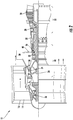
- FIG. 2 is a cross-sectional view of an example of an aircraft engine 12 of FIG. 1 .
- the engine 12 includes a fan 14 having a plurality of fan blades 16, a compressor section 18, a combustor 20, and a turbine section 22.
- the compressor section 18 includes both a low pressure compressor 24 and a high pressure compressor 26 and the turbine section 22 similarly includes both a high pressure turbine 28 and a low pressure turbine 30.
- the high pressure compressor 26 is driven, via a first spool 32, by the high pressure turbine 28.
- the low pressure compressor 24 is driven, via a second spool 34, by the low pressure turbine 30.
- Also driven by the low pressure turbine 30 are the fan blades 16 of the fan 14, which fan is coupled to the second spool 34 via a gear 36.
- Each engine 12 may employ a dedicated bleed air system, or alternatively, a common bleed air system, for providing compressed or pressurized air to one or more downstream systems, illustrated schematically at 50.
- the downstream systems 50 include but are not limited to, an environmental control system (ECS), a thermal anti-icing system (e.g., an engine and/or wing anti-icing system), etc.
- the bleed air system includes one or more taps or ports configured to extract air from various stages of the engine 12.
- the system includes a first port 38 positioned adjacent the lower pressure compressor 24, and a second port 40 positioned adjacent the high pressure compressor 26.
- the indication of "low pressure” and "high pressure” with respect to the taps 38, 40 is therefore a relative term indicating that the high pressure tap 40 is at a location of higher pressure than the location of the low pressure tap 38. It should be understood that a bleed air system having more than two ports is also within the scope of the disclosure. Further, the first and second ports 38, 40 may be located at any position relative to the engine 12 such that the pressurized air drawn from one of the first and second port 38, 40 has a lower pressure and the pressurized air drawn from the other of the first and second port 38, 40 has a higher pressure.
- the engine and bleed system are illustrated and described herein with reference to an aircraft, it should be understood that engines used in other application, or alternative power sources, such as an auxiliary power unit are also contemplated herein.
- FIGS. 3 and 4 a schematic diagram of various embodiments of a downstream system 50, and more specifically a portion of an environmental control system (ECS) such as a pack for example, are depicted according to non-limiting embodiments.
- the system 50 is configured to receive a first medium A1 having a first pressure via a first port, such as port 38 for example, and receive a second medium A2 having a second pressure via a second port, such as port 40 for example.
- the first and second mediums A1, A2 are bleed air, which is pressurized air originating from i.e.
- bleed air being “bled” from, an engine or auxiliary power unit of the aircraft. It shall be understood that one or more of the temperature, humidity, and pressure of the bleed air can vary based upon the compressor stage and revolutions per minute of the engine or auxiliary power unit from which the air is drawn.
- the ECS 50 includes a compression device 60.
- the compression device 60 of the ECS 50 is a mechanical device that includes components for performing thermodynamic work on one or more mediums (e.g., extracts work from or applies work to the first medium A1 and/or the second medium A2 by raising and/or lowering pressure and by raising and/or lowering temperature).
- Examples of the compression device 60 include, but are not limited to, an air cycle machine, such as a three-wheel or four-wheel air cycle machine.
- the compression device 60 includes a compressor 62, a first turbine 64, and a second turbine 66 operably coupled to one another via a shaft 68.
- the compressor 42 is a mechanical device that raises a pressure of a medium and can be driven by another mechanical device (e.g., a motor or a medium via a turbine). Examples of compressor types include centrifugal, diagonal or mixed-flow, axial-flow, reciprocating, ionic liquid piston, rotary screw, rotary vane, scroll, diaphragm, air bubble, etc.
- the compressor 62 is configured to receive and pressurize the first medium A1.
- the first turbine 64 and the second turbine 66 are mechanical devices that expand a medium and extract work therefrom (also referred to as extracting energy). In the compression device 60, the turbines 64, 66 drive the compressor 62 via the shaft 68.
- the system 50 additionally includes one or more heat exchangers or devices configured to provide efficient heat transfer from one medium to another.
- heat exchangers include, but are not limited to, double pipe, shell and tube, plate, plate and shell, adiabatic shell, plate fin, pillow plate, and fluid heat exchangers.
- the one or more heat exchangers includes a first precooler 70 arranged upstream from the compressor 62 and a second precooler 72 arranged upstream from the second turbine 64.
- ram air such as outside air for example, acts as a heat sink to cool a medium passing there through, for example the first medium A1 and/or the second medium A2.
- any suitable cooling medium such as a fluid from another system of the aircraft for example, may be supplied to either of the precoolers 70, 72 to cool the first and/or second mediums A1, A2.
- the system 50 additionally includes a secondary heat exchanger 74 arranged downstream from the compressor 62.
- Ram air, or a fluid from another system of the aircraft may be arranged in a heat exchange relationship with the fluid within the secondary heat exchanger 74.
- the illustrated system 50 is substantially similar to the system 50 of FIG. 3 .
- the system 50 of FIG. 4 additionally includes at least one of a first load heat exchanger 76 arranged downstream from the first turbine 64, and a second load heat exchanger 78 arranged downstream from the second turbine 66.
- the first medium and second medium A1, A2 may be used to transfer heat to or from another fluid associated with the aircraft, such as a coolant used to cool aircraft avionics for example.
- the systems 50 disclosed in FIGS. 3 and 4 are operable in a plurality of modes, selectable based on a flight condition of the aircraft.
- the system 50 may be operable in a first mode when the aircraft is at a high altitude, in a cruise condition, or during a climb, and may be operable in a second mode when the aircraft is at a low altitude or on the ground, such as during idle, taxi or take-off for example, or during descent.
- the first mode of the system 20 may be considered a medium or high engine power / low ECS demand mode.
- the medium or high engine power / low ECS demand mode can be used at high altitude, cruise, and climb flight conditions. Depending on the cooling demand of the aircraft, the amount of bleed air needed to meet one or more demands of the aircraft can be reduced. Accordingly, during operation of the system in the first mode, the first bleed port 38 is open, and a low temperature, low pressure first medium A1 is provided to a first fluid flow path of the system. In an embodiment, the low pressure first medium A1 is drawn from a low pressure spool of an engine compressor. It should be noted that during the first mode of operation, the second bleed port 40 is not open, or is open only a minimal amount sufficient to prevent a stall or malfunction of the second turbine 66.
- the first medium A1 from the first bleed port 38 is supplied to the first precooler 70, where the first medium is cooled via a flow of ram air or other available aircraft heatsinks.
- the first medium A1 is supplied to the compressor 62 of the compression device 60. The act of compressing the first medium A1, heats the first medium A1.
- the compressed first medium A1 then enters the secondary heat exchanger 74 where the first medium A1 is further cooled, such as by a flow of ram air for example.
- the cool first medium A1 is provided to the first turbine 64.
- the cool, high pressure first medium A1 is expanded across the turbine 64 and work extracted from the cool high pressure air. This extracted work drives the compressor 62 used to compress the first medium A1, upstream from the first turbine 64.
- the first medium is provided to one or more downstream loads. In the embodiment of FIG. 3 , the first medium is used to condition the cabin of the aircraft. However, in the embodiment of FIG. 4 , the first medium A1 may be sent to other loads of the aircraft, such as to one or more heat exchangers, such as the first load heat exchanger 76 for example, before being exhausted overboard.
- the second mode may be considered a low engine power / high ECS demand mode that can be used in engine idle settings such as taxi and descent.
- the second bleed port 40 is also open such that a second medium A2 is provided to a second fluid flow path of the system 50.
- the high pressure second medium A2 is drawn from another portion of the engine compressor, or alternatively, from the fan of the engine. Accordingly, the pressure of the second medium A2 may be higher or lower than the pressure of the first medium A1.
- the first fluid flow path and a second fluid flow path of the ECS 50 are arranged in parallel. However, embodiments where these flow paths intersect one another are also within the scope of the disclosure.
- the second medium A2 from the second bleed port 40 is provided to the second precooler 72, where the second medium is at least partially cooled via a flow of ram air or other available aircraft heat sinks.
- the second precooler 72 From the second precooler 72, the second medium A2 is provided to second turbine 66.
- the cool, high pressure second medium A2 is expanded across the turbine 66 and work is extracted from the cool high pressure air. This extracted work drives the compressor 62 used to compress the first medium A1.
- the second medium A2 is provided to one or more downstream loads, such as to the cabin of the aircraft.
- the second medium A2 may be supplied to another loads of the aircraft, such as to one or more heat exchangers, such as the first load heat exchanger 76 for example, before being exhausted overboard.
- a system 50 having a first and second bleed port 38, 40 arranged in fluid communication with a first fluid flow path and a second fluid flow path, respectively, of an environmental control system has enhanced flexibility and adaptability compared to existing environmental control systems.
- Inclusion of a second bleed port 40 selectively operable to provide a higher pressure medium allows various portions the system 50, and specifically the components of the compression device 60, to receive a fluid flow having an optimal temperature or pressure associated with that component. Such optimization results in improved system performance, providing fuel burn benefits and potential volume and/or weight savings.
Landscapes
- Engineering & Computer Science (AREA)
- Health & Medical Sciences (AREA)
- General Health & Medical Sciences (AREA)
- Pulmonology (AREA)
- Aviation & Aerospace Engineering (AREA)
- Chemical & Material Sciences (AREA)
- Combustion & Propulsion (AREA)
- Mechanical Engineering (AREA)
- General Engineering & Computer Science (AREA)
- Structures Of Non-Positive Displacement Pumps (AREA)
Abstract
Description
- This invention was made with Government support under FA8650-16-D-2617 awarded by the United States Air Force. The Government has certain rights in the invention.
- Embodiments of the present disclosure relate to an environmental control system for an aircraft, and more particularly, to an environmental control system capable of extracting both high and low pressure compressed air for uses on an aircraft.
- Aircraft commonly employ an environmental control system to pressurize a passenger cabin of the aircraft and/or thermal anti-icing systems to provide heated air for anti-icing applications. Air supply to these systems is typically provided by bleed air extracted from or provided by a compressor of an aircraft engine. To meet pressure and/or temperature demands of the various aircraft systems, bleed air is often extracted from a high stage of a low-pressure compressor of the aircraft engine. Although systems exist having multiple bleed ports configured to deliver bleed air having various temperatures and/or pressures to the system, only one of these ports is provided as a source at any given time. As a result, operation of the system is limited by the distinct temperatures and pressures available from each port individually.
- According to an embodiment, an environmental control system of an aircraft includes at least one heat exchanger and a compression device arranged in fluid communication with the at least one heat exchanger. The compression device includes a plurality of components including a first component and a second component coupled by a shaft. A first bleed port is arranged in fluid communication with the first component and a second bleed port, distinct from the first bleed port, is arranged in fluid communication with the second component.
- In addition to one or more of the features described above, or as an alternative, in further embodiments a first medium drawn from the first bleed port has a first pressure and a second medium drawn from the second port has a second pressure, the second pressure being higher than the first pressure.
- In addition to one or more of the features described above, or as an alternative, in further embodiments at least one of the first bleed port and the second bleed port is in fluid communication with an engine of the aircraft.
- In addition to one or more of the features described above, or as an alternative, in further embodiments at least one of the first bleed port and the second bleed port is arranged in fluid communication with a low pressure spool of a compressor of the engine.
- In addition to one or more of the features described above, or as an alternative, in further embodiments at least one of the first bleed port and the second bleed port is in fluid communication with an auxiliary power unit of the aircraft.
- In addition to one or more of the features described above, or as an alternative, in further embodiments the first component is a compressor and the second component is a turbine.
- In addition to one or more of the features described above, or as an alternative, in further embodiments the plurality of components of the compression device further includes another turbine arranged downstream from and in fluid communication with the compressor.
- In addition to one or more of the features described above, or as an alternative, in further embodiments the environmental control system is operable in a first mode and a second mode.
- In addition to one or more of the features described above, or as an alternative, in further embodiments the environmental control system is operable in a first mode during conditions with a medium or high engine power setting and/or a low environmental control system demand.
- In addition to one or more of the features described above, or as an alternative, in further embodiments conditions with a medium or high engine power setting and/or a low environmental control system demand include at least one of a cruise and climb of the aircraft.
- In addition to one or more of the features described above, or as an alternative, in further embodiments during operation of the environmental control system in the first mode, fluid from the first bleed port is provided to the first component, but no fluid from the second bleed port is provided to the second component.
- In addition to one or more of the features described above, or as an alternative, in further embodiments the environmental control system is operable in a second mode during conditions with a low engine power setting and/or a high environmental control system demand.
- In addition to one or more of the features described above, or as an alternative, in further embodiments conditions with a medium or high engine power setting and/or a low environmental control system demand include engine idle conditions including taxi, or descent.
- In addition to one or more of the features described above, or as an alternative, in further embodiments during operation of the environmental control system in the second mode, fluid from the first bleed port is provided to the first component, and fluid from the second bleed port is provided to the second component simultaneously.
- In addition to one or more of the features described above, or as an alternative, in further embodiments the at least one heat exchanger includes a secondary heat exchanger is positioned downstream from the compressor.
- In addition to one or more of the features described above, or as an alternative, in further embodiments the at least one heat exchanger includes a first precooler arranged upstream from the first component and a second precooler arranged upstream from the second component.
- In addition to one or more of the features described above, or as an alternative, in further embodiments ram air is arranged in a heat exchange relationship with a first medium provided from the first bleed port in the first precooler.
- In addition to one or more of the features described above, or as an alternative, in further embodiments ram air is arranged in a heat exchange relationship with a second medium provided from the second bleed port in the second precooler.
- In addition to one or more of the features described above, or as an alternative, in further embodiments the second bleed port is selectively operable to tune a flow of fluid provided to the compression device.
- The following descriptions should not be considered limiting in any way. With reference to the accompanying drawings, like elements are numbered alike:
-
FIG. 1 is a perspective view of an example of an aircraft; -
FIG. 2 is a cross-sectional view of an example of a gas turbine engine of an aircraft; -
FIG. 3 is a schematic diagram of a portion of an environmental control system according to an embodiment; and -
FIG. 4 is a schematic diagram of a portion of another environmental control system according to an embodiment. - A detailed description of one or more embodiments of the disclosed apparatus and method are presented herein by way of exemplification and not limitation with reference to the Figures.
- With reference now to
FIG. 1 , an example of anaircraft 10 is illustrated. As shown, theaircraft 10 has a plurality ofengines 12, such as gas turbine engines for example. Although twoengines 12 are illustrated in the FIG., it should be understood that anaircraft 10 having any number ofengines 12, including a single engine, or more than two engines is within the scope of the disclosure. -
FIG. 2 is a cross-sectional view of an example of anaircraft engine 12 ofFIG. 1 . Theengine 12 includes afan 14 having a plurality offan blades 16, acompressor section 18, acombustor 20, and aturbine section 22. Thecompressor section 18 includes both alow pressure compressor 24 and ahigh pressure compressor 26 and theturbine section 22 similarly includes both ahigh pressure turbine 28 and alow pressure turbine 30. Thehigh pressure compressor 26 is driven, via afirst spool 32, by thehigh pressure turbine 28. Thelow pressure compressor 24 is driven, via asecond spool 34, by thelow pressure turbine 30. Also driven by thelow pressure turbine 30 are thefan blades 16 of thefan 14, which fan is coupled to thesecond spool 34 via agear 36. - Each
engine 12 may employ a dedicated bleed air system, or alternatively, a common bleed air system, for providing compressed or pressurized air to one or more downstream systems, illustrated schematically at 50. Examples of thedownstream systems 50 include but are not limited to, an environmental control system (ECS), a thermal anti-icing system (e.g., an engine and/or wing anti-icing system), etc. The bleed air system includes one or more taps or ports configured to extract air from various stages of theengine 12. In the non-limiting embodiment illustrated inFIG. 2 , the system includes afirst port 38 positioned adjacent thelower pressure compressor 24, and asecond port 40 positioned adjacent thehigh pressure compressor 26. The indication of "low pressure" and "high pressure" with respect to thetaps high pressure tap 40 is at a location of higher pressure than the location of thelow pressure tap 38. It should be understood that a bleed air system having more than two ports is also within the scope of the disclosure. Further, the first andsecond ports engine 12 such that the pressurized air drawn from one of the first andsecond port second port - With reference now to
FIGS. 3 and4 , a schematic diagram of various embodiments of adownstream system 50, and more specifically a portion of an environmental control system (ECS) such as a pack for example, are depicted according to non-limiting embodiments. As shown in each of the FIGS., thesystem 50 is configured to receive a first medium A1 having a first pressure via a first port, such asport 38 for example, and receive a second medium A2 having a second pressure via a second port, such asport 40 for example. As previously described, in embodiments where the environmental control system is used in an aircraft application, the first and second mediums A1, A2 are bleed air, which is pressurized air originating from i.e. being "bled" from, an engine or auxiliary power unit of the aircraft. It shall be understood that one or more of the temperature, humidity, and pressure of the bleed air can vary based upon the compressor stage and revolutions per minute of the engine or auxiliary power unit from which the air is drawn. - With reference to
FIG. 3 , the ECS 50 includes acompression device 60. In the illustrated, non-limiting embodiment, thecompression device 60 of theECS 50 is a mechanical device that includes components for performing thermodynamic work on one or more mediums (e.g., extracts work from or applies work to the first medium A1 and/or the second medium A2 by raising and/or lowering pressure and by raising and/or lowering temperature). Examples of thecompression device 60 include, but are not limited to, an air cycle machine, such as a three-wheel or four-wheel air cycle machine. - As shown, the
compression device 60 includes acompressor 62, afirst turbine 64, and asecond turbine 66 operably coupled to one another via ashaft 68. The compressor 42 is a mechanical device that raises a pressure of a medium and can be driven by another mechanical device (e.g., a motor or a medium via a turbine). Examples of compressor types include centrifugal, diagonal or mixed-flow, axial-flow, reciprocating, ionic liquid piston, rotary screw, rotary vane, scroll, diaphragm, air bubble, etc. As shown, thecompressor 62 is configured to receive and pressurize the first medium A1. Thefirst turbine 64 and thesecond turbine 66 are mechanical devices that expand a medium and extract work therefrom (also referred to as extracting energy). In thecompression device 60, theturbines compressor 62 via theshaft 68. - The
system 50 additionally includes one or more heat exchangers or devices configured to provide efficient heat transfer from one medium to another. Examples of the type of heat exchangers that may be used, include, but are not limited to, double pipe, shell and tube, plate, plate and shell, adiabatic shell, plate fin, pillow plate, and fluid heat exchangers. - As shown, the one or more heat exchangers includes a
first precooler 70 arranged upstream from thecompressor 62 and asecond precooler 72 arranged upstream from thesecond turbine 64. In an embodiment, within theprecoolers precoolers precoolers system 50 additionally includes asecondary heat exchanger 74 arranged downstream from thecompressor 62. Ram air, or a fluid from another system of the aircraft may be arranged in a heat exchange relationship with the fluid within thesecondary heat exchanger 74. - Referring now to
FIG. 4 , the illustratedsystem 50 is substantially similar to thesystem 50 ofFIG. 3 . However, thesystem 50 ofFIG. 4 additionally includes at least one of a first load heat exchanger 76 arranged downstream from thefirst turbine 64, and a second load heat exchanger 78 arranged downstream from thesecond turbine 66. Within the first and second load heat exchangers 76, 78, the first medium and second medium A1, A2 may be used to transfer heat to or from another fluid associated with the aircraft, such as a coolant used to cool aircraft avionics for example. - The
systems 50 disclosed inFIGS. 3 and4 are operable in a plurality of modes, selectable based on a flight condition of the aircraft. For example, thesystem 50 may be operable in a first mode when the aircraft is at a high altitude, in a cruise condition, or during a climb, and may be operable in a second mode when the aircraft is at a low altitude or on the ground, such as during idle, taxi or take-off for example, or during descent. - The first mode of the
system 20 may be considered a medium or high engine power / low ECS demand mode. The medium or high engine power / low ECS demand mode can be used at high altitude, cruise, and climb flight conditions. Depending on the cooling demand of the aircraft, the amount of bleed air needed to meet one or more demands of the aircraft can be reduced. Accordingly, during operation of the system in the first mode, thefirst bleed port 38 is open, and a low temperature, low pressure first medium A1 is provided to a first fluid flow path of the system. In an embodiment, the low pressure first medium A1 is drawn from a low pressure spool of an engine compressor. It should be noted that during the first mode of operation, thesecond bleed port 40 is not open, or is open only a minimal amount sufficient to prevent a stall or malfunction of thesecond turbine 66. - Within the first fluid flow path, the first medium A1 from the
first bleed port 38 is supplied to thefirst precooler 70, where the first medium is cooled via a flow of ram air or other available aircraft heatsinks. From thefirst precooler 70, the first medium A1 is supplied to thecompressor 62 of thecompression device 60. The act of compressing the first medium A1, heats the first medium A1. The compressed first medium A1 then enters thesecondary heat exchanger 74 where the first medium A1 is further cooled, such as by a flow of ram air for example. - From the
secondary heat exchanger 74, the cool first medium A1 is provided to thefirst turbine 64. The cool, high pressure first medium A1 is expanded across theturbine 64 and work extracted from the cool high pressure air. This extracted work drives thecompressor 62 used to compress the first medium A1, upstream from thefirst turbine 64. From thefirst turbine 64, the first medium is provided to one or more downstream loads. In the embodiment ofFIG. 3 , the first medium is used to condition the cabin of the aircraft. However, in the embodiment ofFIG. 4 , the first medium A1 may be sent to other loads of the aircraft, such as to one or more heat exchangers, such as the first load heat exchanger 76 for example, before being exhausted overboard. - During operation in the second mode, the flow of first medium A1 along the first fluid flow path remains the same as in the first mode. The second mode may be considered a low engine power / high ECS demand mode that can be used in engine idle settings such as taxi and descent. However, in the second mode, the
second bleed port 40 is also open such that a second medium A2 is provided to a second fluid flow path of thesystem 50. In an embodiment, the high pressure second medium A2 is drawn from another portion of the engine compressor, or alternatively, from the fan of the engine. Accordingly, the pressure of the second medium A2 may be higher or lower than the pressure of the first medium A1. As shown, the first fluid flow path and a second fluid flow path of theECS 50 are arranged in parallel. However, embodiments where these flow paths intersect one another are also within the scope of the disclosure. - Within the second fluid flow path, the second medium A2 from the
second bleed port 40 is provided to thesecond precooler 72, where the second medium is at least partially cooled via a flow of ram air or other available aircraft heat sinks. From thesecond precooler 72, the second medium A2 is provided tosecond turbine 66. The cool, high pressure second medium A2 is expanded across theturbine 66 and work is extracted from the cool high pressure air. This extracted work drives thecompressor 62 used to compress the first medium A1. From thesecond turbine 66, the second medium A2 is provided to one or more downstream loads, such as to the cabin of the aircraft. Alternatively, the second medium A2 may be supplied to another loads of the aircraft, such as to one or more heat exchangers, such as the first load heat exchanger 76 for example, before being exhausted overboard. - A
system 50 having a first andsecond bleed port second bleed port 40 selectively operable to provide a higher pressure medium allows various portions thesystem 50, and specifically the components of thecompression device 60, to receive a fluid flow having an optimal temperature or pressure associated with that component. Such optimization results in improved system performance, providing fuel burn benefits and potential volume and/or weight savings. - The term "about" is intended to include the degree of error associated with measurement of the particular quantity based upon the equipment available at the time of filing the application.
- The terminology used herein is for the purpose of describing particular embodiments only and is not intended to be limiting of the present disclosure. As used herein, the singular forms "a", "an" and "the" are intended to include the plural forms as well, unless the context clearly indicates otherwise. It will be further understood that the terms "comprises" and/or "comprising," when used in this specification, specify the presence of stated features, integers, steps, operations, elements, and/or components, but do not preclude the presence or addition of one or more other features, integers, steps, operations, element components, and/or groups thereof.
- While the present disclosure has been described with reference to an exemplary embodiment or embodiments, it will be understood by those skilled in the art that various changes may be made and equivalents may be substituted for elements thereof without departing from the scope of the invention as defined by the claims. In addition, many modifications may be made to adapt a particular situation or material to the teachings of the present disclosure without departing from the scope of the invention. Therefore, it is intended that the present disclosure not be limited to the particular embodiment disclosed as the best mode contemplated for carrying out this present disclosure, but that the present disclosure will include all embodiments falling within the scope of the claims.
Claims (15)
- An environmental control system of an aircraft comprising:at least one heat exchanger (70, 72);a compression device (60) arranged in fluid communication with the at least one heat exchanger, the compression device including a plurality of components including a first component (62) and a second component (64, 66) coupled by a shaft (68);a first bleed port (38) arranged in fluid communication with the first component; anda second bleed port (40), distinct from the first bleed port, arranged in fluid communication with the second component.
- The environmental control system of claim 1, wherein a first medium drawn from the first bleed port has a first pressure and a second medium drawn from the second port has a second pressure, the second pressure being higher than the first pressure.
- The environmental control system of claim 1 or 2, wherein at least one of the first bleed port and the second bleed port is in fluid communication with an engine (12) of the aircraft.
- The environmental control system of claim 3, wherein at least one of the first bleed port and the second bleed port is arranged in fluid communication with a low pressure spool of a compressor (18) of the engine.
- The environmental control system of claim 1 or 2, wherein at least one of the first bleed port and the second bleed port is in fluid communication with an auxiliary power unit of the aircraft.
- The environmental control system of any preceding claim, wherein the first component is a compressor (62) and the second component is a turbine (64, 66).
- The environmental control system of claim 4, wherein the plurality of components of the compression device further includes another turbine (66) arranged downstream from and in fluid communication with the compressor.
- The environmental control system of any preceding claim, wherein the environmental control system is operable in a first mode and a second mode.
- The environmental control system of claim 8, wherein the environmental control system is operable in a first mode during conditions with a medium or high engine power setting and/or a low environmental control system demand.
- The environmental control system of claim 8, wherein during operation of the environmental control system in the first mode, fluid from the first bleed port is provided to the first component, but no fluid from the second bleed port is provided to the second component.
- The environmental control system of claim 8, wherein the environmental control system is operable in a second mode during conditions with a low engine power setting and/or a high environmental control system demand.
- The environmental control system of claim 8, wherein during operation of the environmental control system in the second mode, fluid from the first bleed port is provided to the first component, and fluid from the second bleed port is provided to the second component simultaneously.
- The environmental control system of any preceding claim, wherein the at least one heat exchanger includes a secondary heat exchanger (72) positioned downstream from the compressor.
- The environmental control system of any preceding claim, wherein the at least one heat exchanger includes:a first precooler (70) arranged upstream from the first component; anda second precooler (72) arranged upstream from the second component.
- The environmental control system of any preceding claim, wherein the second bleed port is selectively operable to tune a flow of fluid provided to the compression device.
Applications Claiming Priority (1)
| Application Number | Priority Date | Filing Date | Title |
|---|---|---|---|
| US16/020,449 US10745139B2 (en) | 2018-06-27 | 2018-06-27 | Simultaneous dual engine bleed thermal management system |
Publications (2)
| Publication Number | Publication Date |
|---|---|
| EP3587268A1 true EP3587268A1 (en) | 2020-01-01 |
| EP3587268B1 EP3587268B1 (en) | 2023-04-12 |
Family
ID=66323743
Family Applications (1)
| Application Number | Title | Priority Date | Filing Date |
|---|---|---|---|
| EP19171570.5A Active EP3587268B1 (en) | 2018-06-27 | 2019-04-29 | Simultaneous dual engine bleed thermal management system |
Country Status (2)
| Country | Link |
|---|---|
| US (1) | US10745139B2 (en) |
| EP (1) | EP3587268B1 (en) |
Families Citing this family (5)
| Publication number | Priority date | Publication date | Assignee | Title |
|---|---|---|---|---|
| EP4001116B1 (en) * | 2020-11-18 | 2026-03-25 | Airbus Operations, S.L.U. | Air management system |
| US12116929B2 (en) * | 2022-01-19 | 2024-10-15 | General Electric Company | Bleed flow assembly for a gas turbine engine |
| US11788465B2 (en) | 2022-01-19 | 2023-10-17 | General Electric Company | Bleed flow assembly for a gas turbine engine |
| US12291337B2 (en) | 2022-02-18 | 2025-05-06 | Rtx Corporation | Aircraft hybrid cooling system |
| US11913377B2 (en) | 2022-02-18 | 2024-02-27 | Rtx Corporation | Environmental control systems |
Citations (3)
| Publication number | Priority date | Publication date | Assignee | Title |
|---|---|---|---|---|
| EP2862803A1 (en) * | 2013-10-21 | 2015-04-22 | Rolls-Royce plc | Pneumatic system for an aircraft |
| US20150251765A1 (en) * | 2014-03-07 | 2015-09-10 | Honeywell International Inc. | Low-pressure bleed air aircraft environmental control system |
| US20170233081A1 (en) * | 2016-02-13 | 2017-08-17 | Ge Aviation Systems Llc | Method and aircraft for providing bleed air to an environmental control system |
Family Cites Families (9)
| Publication number | Priority date | Publication date | Assignee | Title |
|---|---|---|---|---|
| GB976564A (en) * | 1962-11-23 | 1964-11-25 | Normalair Ltd | Improvements in or relating to air conditioning of supersonic aircraft |
| US3222883A (en) * | 1963-09-09 | 1965-12-14 | Boeing Co | Temperature and humidity control systems for enclosures |
| US5704218A (en) | 1996-04-08 | 1998-01-06 | United Technologies Corporation | Integrated environmental control system |
| US7607318B2 (en) | 2006-05-25 | 2009-10-27 | Honeywell International Inc. | Integrated environmental control and auxiliary power system for an aircraft |
| US9169024B2 (en) | 2011-05-09 | 2015-10-27 | Honeywell International Inc. | Environmental control system with closed loop pressure cycle |
| US10054051B2 (en) | 2014-04-01 | 2018-08-21 | The Boeing Company | Bleed air systems for use with aircraft and related methods |
| EP3273068A4 (en) * | 2015-03-20 | 2018-11-07 | Mitsubishi Heavy Industries Engine & Turbocharger, Ltd. | Centrifugal compressor and supercharger comprising same |
| US10710745B2 (en) * | 2016-09-08 | 2020-07-14 | Voltaire Incorporated | Engine driven air compressor system for a mobile aviation support cart |
| US10550768B2 (en) | 2016-11-08 | 2020-02-04 | United Technologies Corporation | Intercooled cooled cooling integrated air cycle machine |
-
2018
- 2018-06-27 US US16/020,449 patent/US10745139B2/en active Active
-
2019
- 2019-04-29 EP EP19171570.5A patent/EP3587268B1/en active Active
Patent Citations (3)
| Publication number | Priority date | Publication date | Assignee | Title |
|---|---|---|---|---|
| EP2862803A1 (en) * | 2013-10-21 | 2015-04-22 | Rolls-Royce plc | Pneumatic system for an aircraft |
| US20150251765A1 (en) * | 2014-03-07 | 2015-09-10 | Honeywell International Inc. | Low-pressure bleed air aircraft environmental control system |
| US20170233081A1 (en) * | 2016-02-13 | 2017-08-17 | Ge Aviation Systems Llc | Method and aircraft for providing bleed air to an environmental control system |
Also Published As
| Publication number | Publication date |
|---|---|
| US20200002007A1 (en) | 2020-01-02 |
| EP3587268B1 (en) | 2023-04-12 |
| US10745139B2 (en) | 2020-08-18 |
Similar Documents
| Publication | Publication Date | Title |
|---|---|---|
| EP3945023B1 (en) | Aircraft environmental control system | |
| EP3587268B1 (en) | Simultaneous dual engine bleed thermal management system | |
| EP3945024B1 (en) | Aircraft environmental control system | |
| EP3945028B1 (en) | Aircraft environmental control system | |
| EP4082911B1 (en) | 100% ambient air environmental control system with bleed turbine in series | |
| EP4036013B1 (en) | AIR ARCHITECTURE WITH A SINGLE ACM WITHOUT A SURROUNDING TURBINE | |
| EP4001117A2 (en) | Environmental control system for supersonic commercial aircraft | |
| US20240410625A1 (en) | Regeneration using liquid loop of environmental control system | |
| EP4273044A1 (en) | 100% ambient air environmental control system | |
| EP4520664A1 (en) | Less bleed environmental control system | |
| US12078379B2 (en) | Split regeneration environmental control system | |
| US20250313066A1 (en) | Environmental control system with mixed bleed and ambient pack | |
| US20260028127A1 (en) | Bleed air powered ambient aircraft environmental control system |
Legal Events
| Date | Code | Title | Description |
|---|---|---|---|
| PUAI | Public reference made under article 153(3) epc to a published international application that has entered the european phase |
Free format text: ORIGINAL CODE: 0009012 |
|
| STAA | Information on the status of an ep patent application or granted ep patent |
Free format text: STATUS: THE APPLICATION HAS BEEN PUBLISHED |
|
| AK | Designated contracting states |
Kind code of ref document: A1 Designated state(s): AL AT BE BG CH CY CZ DE DK EE ES FI FR GB GR HR HU IE IS IT LI LT LU LV MC MK MT NL NO PL PT RO RS SE SI SK SM TR |
|
| AX | Request for extension of the european patent |
Extension state: BA ME |
|
| STAA | Information on the status of an ep patent application or granted ep patent |
Free format text: STATUS: REQUEST FOR EXAMINATION WAS MADE |
|
| 17P | Request for examination filed |
Effective date: 20200701 |
|
| RBV | Designated contracting states (corrected) |
Designated state(s): AL AT BE BG CH CY CZ DE DK EE ES FI FR GB GR HR HU IE IS IT LI LT LU LV MC MK MT NL NO PL PT RO RS SE SI SK SM TR |
|
| STAA | Information on the status of an ep patent application or granted ep patent |
Free format text: STATUS: EXAMINATION IS IN PROGRESS |
|
| 17Q | First examination report despatched |
Effective date: 20201117 |
|
| GRAP | Despatch of communication of intention to grant a patent |
Free format text: ORIGINAL CODE: EPIDOSNIGR1 |
|
| STAA | Information on the status of an ep patent application or granted ep patent |
Free format text: STATUS: GRANT OF PATENT IS INTENDED |
|
| INTG | Intention to grant announced |
Effective date: 20221108 |
|
| RIN1 | Information on inventor provided before grant (corrected) |
Inventor name: HO, TONY Inventor name: RETERSDORF, ALAN |
|
| GRAS | Grant fee paid |
Free format text: ORIGINAL CODE: EPIDOSNIGR3 |
|
| GRAA | (expected) grant |
Free format text: ORIGINAL CODE: 0009210 |
|
| STAA | Information on the status of an ep patent application or granted ep patent |
Free format text: STATUS: THE PATENT HAS BEEN GRANTED |
|
| AK | Designated contracting states |
Kind code of ref document: B1 Designated state(s): AL AT BE BG CH CY CZ DE DK EE ES FI FR GB GR HR HU IE IS IT LI LT LU LV MC MK MT NL NO PL PT RO RS SE SI SK SM TR |
|
| REG | Reference to a national code |
Ref country code: GB Ref legal event code: FG4D |
|
| REG | Reference to a national code |
Ref country code: CH Ref legal event code: EP |
|
| REG | Reference to a national code |
Ref country code: DE Ref legal event code: R096 Ref document number: 602019027378 Country of ref document: DE |
|
| REG | Reference to a national code |
Ref country code: IE Ref legal event code: FG4D |
|
| REG | Reference to a national code |
Ref country code: AT Ref legal event code: REF Ref document number: 1559650 Country of ref document: AT Kind code of ref document: T Effective date: 20230515 |
|
| P01 | Opt-out of the competence of the unified patent court (upc) registered |
Effective date: 20230522 |
|
| REG | Reference to a national code |
Ref country code: LT Ref legal event code: MG9D |
|
| REG | Reference to a national code |
Ref country code: NL Ref legal event code: MP Effective date: 20230412 |
|
| REG | Reference to a national code |
Ref country code: AT Ref legal event code: MK05 Ref document number: 1559650 Country of ref document: AT Kind code of ref document: T Effective date: 20230412 |
|
| PG25 | Lapsed in a contracting state [announced via postgrant information from national office to epo] |
Ref country code: NL Free format text: LAPSE BECAUSE OF FAILURE TO SUBMIT A TRANSLATION OF THE DESCRIPTION OR TO PAY THE FEE WITHIN THE PRESCRIBED TIME-LIMIT Effective date: 20230412 |
|
| PG25 | Lapsed in a contracting state [announced via postgrant information from national office to epo] |
Ref country code: SE Free format text: LAPSE BECAUSE OF FAILURE TO SUBMIT A TRANSLATION OF THE DESCRIPTION OR TO PAY THE FEE WITHIN THE PRESCRIBED TIME-LIMIT Effective date: 20230412 Ref country code: PT Free format text: LAPSE BECAUSE OF FAILURE TO SUBMIT A TRANSLATION OF THE DESCRIPTION OR TO PAY THE FEE WITHIN THE PRESCRIBED TIME-LIMIT Effective date: 20230814 Ref country code: NO Free format text: LAPSE BECAUSE OF FAILURE TO SUBMIT A TRANSLATION OF THE DESCRIPTION OR TO PAY THE FEE WITHIN THE PRESCRIBED TIME-LIMIT Effective date: 20230712 Ref country code: ES Free format text: LAPSE BECAUSE OF FAILURE TO SUBMIT A TRANSLATION OF THE DESCRIPTION OR TO PAY THE FEE WITHIN THE PRESCRIBED TIME-LIMIT Effective date: 20230412 Ref country code: AT Free format text: LAPSE BECAUSE OF FAILURE TO SUBMIT A TRANSLATION OF THE DESCRIPTION OR TO PAY THE FEE WITHIN THE PRESCRIBED TIME-LIMIT Effective date: 20230412 |
|
| PG25 | Lapsed in a contracting state [announced via postgrant information from national office to epo] |
Ref country code: RS Free format text: LAPSE BECAUSE OF FAILURE TO SUBMIT A TRANSLATION OF THE DESCRIPTION OR TO PAY THE FEE WITHIN THE PRESCRIBED TIME-LIMIT Effective date: 20230412 Ref country code: PL Free format text: LAPSE BECAUSE OF FAILURE TO SUBMIT A TRANSLATION OF THE DESCRIPTION OR TO PAY THE FEE WITHIN THE PRESCRIBED TIME-LIMIT Effective date: 20230412 Ref country code: LV Free format text: LAPSE BECAUSE OF FAILURE TO SUBMIT A TRANSLATION OF THE DESCRIPTION OR TO PAY THE FEE WITHIN THE PRESCRIBED TIME-LIMIT Effective date: 20230412 Ref country code: LT Free format text: LAPSE BECAUSE OF FAILURE TO SUBMIT A TRANSLATION OF THE DESCRIPTION OR TO PAY THE FEE WITHIN THE PRESCRIBED TIME-LIMIT Effective date: 20230412 Ref country code: IS Free format text: LAPSE BECAUSE OF FAILURE TO SUBMIT A TRANSLATION OF THE DESCRIPTION OR TO PAY THE FEE WITHIN THE PRESCRIBED TIME-LIMIT Effective date: 20230812 Ref country code: HR Free format text: LAPSE BECAUSE OF FAILURE TO SUBMIT A TRANSLATION OF THE DESCRIPTION OR TO PAY THE FEE WITHIN THE PRESCRIBED TIME-LIMIT Effective date: 20230412 Ref country code: GR Free format text: LAPSE BECAUSE OF FAILURE TO SUBMIT A TRANSLATION OF THE DESCRIPTION OR TO PAY THE FEE WITHIN THE PRESCRIBED TIME-LIMIT Effective date: 20230713 Ref country code: AL Free format text: LAPSE BECAUSE OF FAILURE TO SUBMIT A TRANSLATION OF THE DESCRIPTION OR TO PAY THE FEE WITHIN THE PRESCRIBED TIME-LIMIT Effective date: 20230412 |
|
| REG | Reference to a national code |
Ref country code: CH Ref legal event code: PL |
|
| PG25 | Lapsed in a contracting state [announced via postgrant information from national office to epo] |
Ref country code: LU Free format text: LAPSE BECAUSE OF NON-PAYMENT OF DUE FEES Effective date: 20230429 Ref country code: FI Free format text: LAPSE BECAUSE OF FAILURE TO SUBMIT A TRANSLATION OF THE DESCRIPTION OR TO PAY THE FEE WITHIN THE PRESCRIBED TIME-LIMIT Effective date: 20230412 |
|
| REG | Reference to a national code |
Ref country code: BE Ref legal event code: MM Effective date: 20230430 |
|
| REG | Reference to a national code |
Ref country code: DE Ref legal event code: R097 Ref document number: 602019027378 Country of ref document: DE |
|
| PG25 | Lapsed in a contracting state [announced via postgrant information from national office to epo] |
Ref country code: SK Free format text: LAPSE BECAUSE OF FAILURE TO SUBMIT A TRANSLATION OF THE DESCRIPTION OR TO PAY THE FEE WITHIN THE PRESCRIBED TIME-LIMIT Effective date: 20230412 |
|
| PG25 | Lapsed in a contracting state [announced via postgrant information from national office to epo] |
Ref country code: MC Free format text: LAPSE BECAUSE OF FAILURE TO SUBMIT A TRANSLATION OF THE DESCRIPTION OR TO PAY THE FEE WITHIN THE PRESCRIBED TIME-LIMIT Effective date: 20230412 |
|
| PG25 | Lapsed in a contracting state [announced via postgrant information from national office to epo] |
Ref country code: SM Free format text: LAPSE BECAUSE OF FAILURE TO SUBMIT A TRANSLATION OF THE DESCRIPTION OR TO PAY THE FEE WITHIN THE PRESCRIBED TIME-LIMIT Effective date: 20230412 Ref country code: SK Free format text: LAPSE BECAUSE OF FAILURE TO SUBMIT A TRANSLATION OF THE DESCRIPTION OR TO PAY THE FEE WITHIN THE PRESCRIBED TIME-LIMIT Effective date: 20230412 Ref country code: RO Free format text: LAPSE BECAUSE OF FAILURE TO SUBMIT A TRANSLATION OF THE DESCRIPTION OR TO PAY THE FEE WITHIN THE PRESCRIBED TIME-LIMIT Effective date: 20230412 Ref country code: MC Free format text: LAPSE BECAUSE OF FAILURE TO SUBMIT A TRANSLATION OF THE DESCRIPTION OR TO PAY THE FEE WITHIN THE PRESCRIBED TIME-LIMIT Effective date: 20230412 Ref country code: LI Free format text: LAPSE BECAUSE OF NON-PAYMENT OF DUE FEES Effective date: 20230430 Ref country code: EE Free format text: LAPSE BECAUSE OF FAILURE TO SUBMIT A TRANSLATION OF THE DESCRIPTION OR TO PAY THE FEE WITHIN THE PRESCRIBED TIME-LIMIT Effective date: 20230412 Ref country code: DK Free format text: LAPSE BECAUSE OF FAILURE TO SUBMIT A TRANSLATION OF THE DESCRIPTION OR TO PAY THE FEE WITHIN THE PRESCRIBED TIME-LIMIT Effective date: 20230412 Ref country code: CZ Free format text: LAPSE BECAUSE OF FAILURE TO SUBMIT A TRANSLATION OF THE DESCRIPTION OR TO PAY THE FEE WITHIN THE PRESCRIBED TIME-LIMIT Effective date: 20230412 Ref country code: CH Free format text: LAPSE BECAUSE OF NON-PAYMENT OF DUE FEES Effective date: 20230430 |
|
| REG | Reference to a national code |
Ref country code: IE Ref legal event code: MM4A |
|
| PLBE | No opposition filed within time limit |
Free format text: ORIGINAL CODE: 0009261 |
|
| STAA | Information on the status of an ep patent application or granted ep patent |
Free format text: STATUS: NO OPPOSITION FILED WITHIN TIME LIMIT |
|
| PG25 | Lapsed in a contracting state [announced via postgrant information from national office to epo] |
Ref country code: BE Free format text: LAPSE BECAUSE OF NON-PAYMENT OF DUE FEES Effective date: 20230430 |
|
| 26N | No opposition filed |
Effective date: 20240115 |
|
| PG25 | Lapsed in a contracting state [announced via postgrant information from national office to epo] |
Ref country code: IE Free format text: LAPSE BECAUSE OF NON-PAYMENT OF DUE FEES Effective date: 20230429 |
|
| PG25 | Lapsed in a contracting state [announced via postgrant information from national office to epo] |
Ref country code: IE Free format text: LAPSE BECAUSE OF NON-PAYMENT OF DUE FEES Effective date: 20230429 |
|
| PG25 | Lapsed in a contracting state [announced via postgrant information from national office to epo] |
Ref country code: SI Free format text: LAPSE BECAUSE OF FAILURE TO SUBMIT A TRANSLATION OF THE DESCRIPTION OR TO PAY THE FEE WITHIN THE PRESCRIBED TIME-LIMIT Effective date: 20230412 |
|
| PG25 | Lapsed in a contracting state [announced via postgrant information from national office to epo] |
Ref country code: SI Free format text: LAPSE BECAUSE OF FAILURE TO SUBMIT A TRANSLATION OF THE DESCRIPTION OR TO PAY THE FEE WITHIN THE PRESCRIBED TIME-LIMIT Effective date: 20230412 Ref country code: IT Free format text: LAPSE BECAUSE OF FAILURE TO SUBMIT A TRANSLATION OF THE DESCRIPTION OR TO PAY THE FEE WITHIN THE PRESCRIBED TIME-LIMIT Effective date: 20230412 |
|
| PG25 | Lapsed in a contracting state [announced via postgrant information from national office to epo] |
Ref country code: BG Free format text: LAPSE BECAUSE OF FAILURE TO SUBMIT A TRANSLATION OF THE DESCRIPTION OR TO PAY THE FEE WITHIN THE PRESCRIBED TIME-LIMIT Effective date: 20230412 |
|
| PG25 | Lapsed in a contracting state [announced via postgrant information from national office to epo] |
Ref country code: BG Free format text: LAPSE BECAUSE OF FAILURE TO SUBMIT A TRANSLATION OF THE DESCRIPTION OR TO PAY THE FEE WITHIN THE PRESCRIBED TIME-LIMIT Effective date: 20230412 |
|
| PGFP | Annual fee paid to national office [announced via postgrant information from national office to epo] |
Ref country code: DE Payment date: 20250319 Year of fee payment: 7 |
|
| PG25 | Lapsed in a contracting state [announced via postgrant information from national office to epo] |
Ref country code: CY Free format text: LAPSE BECAUSE OF FAILURE TO SUBMIT A TRANSLATION OF THE DESCRIPTION OR TO PAY THE FEE WITHIN THE PRESCRIBED TIME-LIMIT; INVALID AB INITIO Effective date: 20190429 |
|
| PG25 | Lapsed in a contracting state [announced via postgrant information from national office to epo] |
Ref country code: HU Free format text: LAPSE BECAUSE OF FAILURE TO SUBMIT A TRANSLATION OF THE DESCRIPTION OR TO PAY THE FEE WITHIN THE PRESCRIBED TIME-LIMIT; INVALID AB INITIO Effective date: 20190429 |
|
| PG25 | Lapsed in a contracting state [announced via postgrant information from national office to epo] |
Ref country code: TR Free format text: LAPSE BECAUSE OF FAILURE TO SUBMIT A TRANSLATION OF THE DESCRIPTION OR TO PAY THE FEE WITHIN THE PRESCRIBED TIME-LIMIT Effective date: 20230412 |
|
| PGFP | Annual fee paid to national office [announced via postgrant information from national office to epo] |
Ref country code: GB Payment date: 20260319 Year of fee payment: 8 |
|
| PGFP | Annual fee paid to national office [announced via postgrant information from national office to epo] |
Ref country code: FR Payment date: 20260320 Year of fee payment: 8 |