EP3587257B1 - Removable struts for vibration isolation device mounting system - Google Patents
Removable struts for vibration isolation device mounting system Download PDFInfo
- Publication number
- EP3587257B1 EP3587257B1 EP18188732.4A EP18188732A EP3587257B1 EP 3587257 B1 EP3587257 B1 EP 3587257B1 EP 18188732 A EP18188732 A EP 18188732A EP 3587257 B1 EP3587257 B1 EP 3587257B1
- Authority
- EP
- European Patent Office
- Prior art keywords
- strut
- spindle
- elastomeric member
- piston
- bonded
- Prior art date
- Legal status (The legal status is an assumption and is not a legal conclusion. Google has not performed a legal analysis and makes no representation as to the accuracy of the status listed.)
- Active
Links
Images




Classifications
-
- B—PERFORMING OPERATIONS; TRANSPORTING
- B64—AIRCRAFT; AVIATION; COSMONAUTICS
- B64C—AEROPLANES; HELICOPTERS
- B64C27/00—Rotorcraft; Rotors peculiar thereto
- B64C27/001—Vibration damping devices
-
- B—PERFORMING OPERATIONS; TRANSPORTING
- B64—AIRCRAFT; AVIATION; COSMONAUTICS
- B64D—EQUIPMENT FOR FITTING IN OR TO AIRCRAFT; FLIGHT SUITS; PARACHUTES; ARRANGEMENT OR MOUNTING OF POWER PLANTS OR PROPULSION TRANSMISSIONS IN AIRCRAFT
- B64D27/00—Arrangement or mounting of power plants in aircraft; Aircraft characterised by the type or position of power plants
- B64D27/40—Arrangements for mounting power plants in aircraft
- B64D27/402—Arrangements for mounting power plants in aircraft comprising box like supporting frames, e.g. pylons or arrangements for embracing the power plant
-
- F—MECHANICAL ENGINEERING; LIGHTING; HEATING; WEAPONS; BLASTING
- F16—ENGINEERING ELEMENTS AND UNITS; GENERAL MEASURES FOR PRODUCING AND MAINTAINING EFFECTIVE FUNCTIONING OF MACHINES OR INSTALLATIONS; THERMAL INSULATION IN GENERAL
- F16F—SPRINGS; SHOCK-ABSORBERS; MEANS FOR DAMPING VIBRATION
- F16F13/00—Units comprising springs of the non-fluid type as well as vibration-dampers, shock-absorbers, or fluid springs
- F16F13/04—Units comprising springs of the non-fluid type as well as vibration-dampers, shock-absorbers, or fluid springs comprising both a plastics spring and a damper, e.g. a friction damper
- F16F13/06—Units comprising springs of the non-fluid type as well as vibration-dampers, shock-absorbers, or fluid springs comprising both a plastics spring and a damper, e.g. a friction damper the damper being a fluid damper, e.g. the plastics spring not forming a part of the wall of the fluid chamber of the damper
- F16F13/24—Units comprising springs of the non-fluid type as well as vibration-dampers, shock-absorbers, or fluid springs comprising both a plastics spring and a damper, e.g. a friction damper the damper being a fluid damper, e.g. the plastics spring not forming a part of the wall of the fluid chamber of the damper the central part of the unit being supported by one element and both extremities of the unit being supported by a single other element, i.e. double acting mounting
-
- B—PERFORMING OPERATIONS; TRANSPORTING
- B64—AIRCRAFT; AVIATION; COSMONAUTICS
- B64C—AEROPLANES; HELICOPTERS
- B64C27/00—Rotorcraft; Rotors peculiar thereto
- B64C27/001—Vibration damping devices
- B64C2027/002—Vibration damping devices mounted between the rotor drive and the fuselage
-
- F—MECHANICAL ENGINEERING; LIGHTING; HEATING; WEAPONS; BLASTING
- F16—ENGINEERING ELEMENTS AND UNITS; GENERAL MEASURES FOR PRODUCING AND MAINTAINING EFFECTIVE FUNCTIONING OF MACHINES OR INSTALLATIONS; THERMAL INSULATION IN GENERAL
- F16F—SPRINGS; SHOCK-ABSORBERS; MEANS FOR DAMPING VIBRATION
- F16F13/00—Units comprising springs of the non-fluid type as well as vibration-dampers, shock-absorbers, or fluid springs
- F16F13/04—Units comprising springs of the non-fluid type as well as vibration-dampers, shock-absorbers, or fluid springs comprising both a plastics spring and a damper, e.g. a friction damper
- F16F13/06—Units comprising springs of the non-fluid type as well as vibration-dampers, shock-absorbers, or fluid springs comprising both a plastics spring and a damper, e.g. a friction damper the damper being a fluid damper, e.g. the plastics spring not forming a part of the wall of the fluid chamber of the damper
- F16F13/08—Units comprising springs of the non-fluid type as well as vibration-dampers, shock-absorbers, or fluid springs comprising both a plastics spring and a damper, e.g. a friction damper the damper being a fluid damper, e.g. the plastics spring not forming a part of the wall of the fluid chamber of the damper the plastics spring forming at least a part of the wall of the fluid chamber of the damper
- F16F13/085—Units comprising springs of the non-fluid type as well as vibration-dampers, shock-absorbers, or fluid springs comprising both a plastics spring and a damper, e.g. a friction damper the damper being a fluid damper, e.g. the plastics spring not forming a part of the wall of the fluid chamber of the damper the plastics spring forming at least a part of the wall of the fluid chamber of the damper characterised by features of plastics springs; Attachment arrangements
-
- F—MECHANICAL ENGINEERING; LIGHTING; HEATING; WEAPONS; BLASTING
- F16—ENGINEERING ELEMENTS AND UNITS; GENERAL MEASURES FOR PRODUCING AND MAINTAINING EFFECTIVE FUNCTIONING OF MACHINES OR INSTALLATIONS; THERMAL INSULATION IN GENERAL
- F16F—SPRINGS; SHOCK-ABSORBERS; MEANS FOR DAMPING VIBRATION
- F16F13/00—Units comprising springs of the non-fluid type as well as vibration-dampers, shock-absorbers, or fluid springs
- F16F13/04—Units comprising springs of the non-fluid type as well as vibration-dampers, shock-absorbers, or fluid springs comprising both a plastics spring and a damper, e.g. a friction damper
- F16F13/06—Units comprising springs of the non-fluid type as well as vibration-dampers, shock-absorbers, or fluid springs comprising both a plastics spring and a damper, e.g. a friction damper the damper being a fluid damper, e.g. the plastics spring not forming a part of the wall of the fluid chamber of the damper
- F16F13/08—Units comprising springs of the non-fluid type as well as vibration-dampers, shock-absorbers, or fluid springs comprising both a plastics spring and a damper, e.g. a friction damper the damper being a fluid damper, e.g. the plastics spring not forming a part of the wall of the fluid chamber of the damper the plastics spring forming at least a part of the wall of the fluid chamber of the damper
- F16F13/10—Units comprising springs of the non-fluid type as well as vibration-dampers, shock-absorbers, or fluid springs comprising both a plastics spring and a damper, e.g. a friction damper the damper being a fluid damper, e.g. the plastics spring not forming a part of the wall of the fluid chamber of the damper the plastics spring forming at least a part of the wall of the fluid chamber of the damper the wall being at least in part formed by a flexible membrane or the like
- F16F13/103—Units comprising springs of the non-fluid type as well as vibration-dampers, shock-absorbers, or fluid springs comprising both a plastics spring and a damper, e.g. a friction damper the damper being a fluid damper, e.g. the plastics spring not forming a part of the wall of the fluid chamber of the damper the plastics spring forming at least a part of the wall of the fluid chamber of the damper the wall being at least in part formed by a flexible membrane or the like characterised by method of assembly, production or treatment
Definitions
- the present invention relates in general to the field of vibration control, and more particularly, to a vibration isolation device mounting system.
- the vibration isolator is utilized in a pylon system for mounting a transmission in an aircraft.
- the vibration isolator is located between a pylon structure and a roof structure.
- the isolator includes a spherical bearing assembly that is located near a waterline location of a rotational axis of a drive shaft.
- the vibration isolation device is utilized in a pylon system for mounting a transmission in an aircraft.
- the vibration isolation device is located between a pylon structure and a roof structure.
- the isolator includes a spherical bearing assembly that is located near a waterline location of a rotational axis of a drive shaft.
- the vibration isolator includes an upper housing and a lower housing; an upper reservoir housing defining a upper fluid chamber; a lower reservoir housing defining a lower fluid chamber; a piston spindle resiliently coupled to the upper housing with an upper elastomer member, the piston spindle being resiliently coupled to the lower housing with a lower elastomer member; an inertia track having a tuning passage, the inertia track being removably coupled to the piston spindle; and a tuning fluid disposed within the upper fluid chamber, the lower fluid chamber, and the tuning passage.
- the vibration isolator cancels vibratory forces at an isolation frequency, the isolation frequency being at least partially dependent upon a size of the tuning passage.
- a strut assembly for a vibration isolation device includes a piston spindle; a first elastomeric member bonded to the piston spindle; a second elastomeric member bonded to the piston spindle; an upper housing in contact with the first elastomeric member; a lower housing in contact with the second elastomeric member; a first strut support attached to, or integral with, the upper housing; a second strut support attached to, or integral with, the lower housing; a first strut spindle configured to be placed in the first strut support; a second strut spindle configured to be placed in the second strut support; and one or more removable struts configured to be engaged at a first end to the first strut spindle and at a second end to the second strut spindle, without engagement of the first end to the first strut support or engagement of the second end to the second strut support, wherein at least one of the first or second strut spindles
- the first elastomeric member or the second elastomeric member comprises rubber, plastics, composites, or layered materials.
- the first elastomeric member is bonded to the piston spindle or the second elastomeric member is bonded to the piston spindle using an elastomer-to-substrate adhesive, and the first elastomeric member or the second elastomeric member is molded and adhered to the piston spindle during a vulcanization process or bonded using a post-vulcanization process.
- the one or more removable struts is configured to be threaded or slotted at a first end to the first strut spindle and configured to be threaded or slotted at a second end to the second strut spindle.
- the one or more removable struts further comprise one or more surfaces on at least a portion of the strut to be engaged by a wrench.
- method of replacing a strut of a vibration isolation device includes providing the vibration isolation device including a piston spindle; a first elastomeric member bonded to the piston spindle; a second elastomeric member bonded to the piston spindle; an upper housing in contact with the first elastomeric member; a lower housing in contact with the second elastomeric member; a first strut support attached to or integral with the upper housing; a second strut support attached to or integral with the lower housing; and one or more struts removably configured to be engaged at a first end to the first strut spindle and at a second end to the second strut spindle, without engagement of the first end to the first strut support or engagement of the second end to the second strut support; placing a first strut spindle in the first strut support; placing a second strut spindle in the second strut support; engaging a first end of at least one of the one or more
- the first elastomeric member or the second elastomeric member comprises rubber, plastics, composites, or layered materials.
- the first elastomeric member is bonded to the piston spindle or the second elastomeric member is bonded to the piston spindle using an elastomer-to-substrate adhesive, and the first elastomeric member or the second elastomeric member is molded and adhered to the piston spindle during a vulcanization process or bonded using a post-vulcanization process.
- the strut is threaded or slotted at a first end to the first strut spindle and threaded or slotted at a second end to the second strut spindle.
- the one or more removable struts further comprise one or more surfaces on at least a portion of the strut to be engaged by a wrench.
- a method of removing a strut from a vibration isolation device includes providing the vibration isolation device including a piston spindle; a first elastomeric member bonded to the piston spindle; a second elastomeric member bonded to the piston spindle; an upper housing in contact with the first elastomeric member; a lower housing in contact with the second elastomeric member; a first strut support attached to or integral with the upper housing; a second strut support attached to or integral with the lower housing; a first strut spindle configured to be placed in the first strut support; a second strut spindle configured to be placed in the second strut support; and one or more removable struts engaged at a first end to the first strut spindle and engaged at a second end to the second strut spindle, without engagement of the first end to the first strut support or engagement of the second end to the second strut support; applying a load to displace either the first
- the first elastomeric member or the second elastomeric member comprises rubber, plastics, composites, or layered materials.
- the first elastomeric member is bonded to the piston spindle or the second elastomeric member is bonded to the piston spindle using an elastomer-to-substrate adhesive, and the first elastomeric member or the second elastomeric member is molded and adhered to the piston spindle during a vulcanization process or bonded using a post-vulcanization process.
- the strut is threaded or slotted at a first end to the first strut spindle and threaded or slotted at a second end to the second strut spindle.
- the one or more removable struts further comprise one or more surfaces on at least a portion of the strut to be engaged by a wrench.
- a rotorcraft in an example not forming part of the present invention, includes a fuselage; one or more engines; and a vibration isolation device coupled to the fuselage, the vibration isolation device including a piston spindle; a first elastomeric member bonded to the piston spindle; a second elastomeric member bonded to the piston spindle; an upper housing in contact with the first elastomeric member; a lower housing in contact with the second elastomeric member; a first strut support attached to or integral with the upper housing; a second strut support attached to or integral with the lower housing; a first strut spindle configured to be placed in the first strut support; a second strut spindle configured to be placed in the second strut support; and one or more struts engaged at a first end to the first strut spindle and engaged at a second end to the second strut spindle, without engagement of the first end to the first strut support or engagement of the second end to
- the first elastomeric member or the second elastomeric member comprises rubber, plastics, composites, or layered materials.
- the first elastomeric member is bonded to the piston spindle or the second elastomeric member is bonded to the piston spindle using an elastomer-to-substrate adhesive, and the first elastomeric member or the second elastomeric member is molded and adhered to the piston spindle during a vulcanization process or bonded using a post-vulcanization process.
- the strut is threaded or slotted at a first end to the first strut spindle and threaded or slotted at a second end to the second strut spindle.
- the one or more removable struts further comprise one or more surfaces on at least a portion of the strut to be engaged by a wrench.
- aircraft 100 in accordance with a preferred embodiment of the present application is shown.
- aircraft 100 is a helicopter having a fuselage 102 and a rotor system 104 carried thereon.
- a plurality of rotor blades 106 is operably associated with rotor system 104 for creating flight.
- a tail boom 108 is depicted that further includes tail rotor 110.
- the system of the present invention can be used in conjunction with an aircraft 100. Although shown associated with a helicopter, it will be appreciated that the mounting system of the present application can also be utilized with different types of aircraft and vehicles.
- the present invention will now be described in reference to one example of a vibration isolation device. It will be appreciated that the mounting system of the present application can be used with other vibration isolation devices, including but not limited to, those described above in the background. Some external changes to the housings may be required.
- the vibration suppression system 200 includes a vibration isolation device 204, also referred to as a vibration isolation device or vibration eliminator, located in each corner in a four-corner pylon mount structural assembly.
- MRGB main rotor gearbox
- rotor hub induced pitch moment vibrations which can become relatively large in high-speed forward flight, can be effectively isolated with the four vibration isolation devices 204a-204d in the corner arrangement.
- the vibration suppression system 200 includes a first roof beam 206a, a second roof beam 206b, a forward cross member 208a, and an aft cross member 208b coupled to the airframe.
- Structural adapters can be used to structurally couple first roof beam 206a and second roof beam 206b with cross members 208a and 208b.
- Support structures (hereinafter referred to as first bipod mount 210a and second bipod mount 210b) are coupled to the first roof beam 206a, and bipod mounts 210c and 210d are coupled to the second roof beam 206b.
- First vibration isolation device 204a is coupled to the first bipod mount 210a using the mounting system described herein.
- second vibration isolation device 204b is coupled to the second bipod mount 210b
- third vibration isolation device 204c is coupled to the third bipod mount 210c
- fourth vibration isolation device 204d is coupled to the fourth bipod mount 210d, all using the mounting system described herein.
- First pylon structure 212a affixed to the MRGB is coupled to and extends between first vibration isolation device 204a and second vibration isolation device 204b.
- second pylon structure 212b affixed to the MRGB is coupled to and extends between third vibration isolation device 204c and fourth vibration isolation device 204d.
- Each vibration isolation device 204a-204d is mounted substantially vertical. It should be appreciated that embodiments of vibration suppression system 200 may employ any practical number of engines and transmissions. Furthermore, it is contemplated that any plurality of pylon structures and vibration isolation devices may be used in a variety of orientations spaced fore, aft, and even inboard of the MRGB.
- Pylon structures 212a, 212b are configured to correlate motion of the MRGB between a plurality of isolation devices 204a-204d simultaneously by suspending a portion of MRGB between the plurality of vibration isolation devices 204a-204d located on opposing ends of the pylon structures 212a-212b.
- the use of pylon structures 212a, 212b permits an aircraft to space the location of vibration isolation devices 204a-204d to an infinite number of locations independent of transmission or main rotor gearbox. Locating vibration isolation devices 204a-204d forward and aft of MRGB minimizes the size of each vibration isolation device 204a-204d and avoids the use of additional elements to control the dynamics of the MRGB.
- the vibration suppression system 200 is springless in that the system 200 does not use a separate spring mounted externally beneath the MRGB to control dynamics of the MRGB.
- the vibration suppression system 200 is configured to control pitch and roll dynamics by spacing of vibration isolation devices 204a-204d and the use of pylon structures 212a and 212b.
- Bipod mounts 210a-210d include a clevis 302 that is used to mount the engine (not shown) via member 304.
- active vibration isolation devices such as piezoelectric vibration isolation devices
- active actuation methods can be used as well, such as hydraulic, electromagnetic, electromechanical, magnetohydrodynamic, to name a few.
- Active vibration isolation devices can also achieve better vibration isolation by overcoming damping losses, and adjusting the frequency response characteristics.
- each opposing pair of vibration isolation devices 204a-204d can efficiently react against the moment oscillations because the moment can be decomposed into two antagonistic vertical oscillations at each vibration isolation device 204.
- Each vibration isolation device 204a-204d includes an upper housing 404 and a lower housing 406 (not shown).
- a plurality of support struts 416 connects the upper housing 404 and the lower housing 406. It is desirable to integrate the struts 416 into a vibration isolation device such that the struts can be removed and installed without damage to the vibration isolation devices 204a-204d. The present invention addresses this desirable feature.
- FIG. 3 shows a typical installation of the prior art.
- integral threads ran through first strut support 320, and strut 316 was held in place in first strut support 320 by being screwed onto it.
- a load was applied to displace either elastomeric member 312 or elastomeric member 314, breaking the bond line between either elastomeric member 312 and piston spindle 308, or between elastomeric member 314 and piston spindle 308.
- the prior art vibration isolation device 306 had to be placed in a fixture to apply a load that displaces either elastomeric member 312 or elastomeric member 314, enough to allow removal of the strut 316, thus requiring a breaking of the bonding with the piston spindle 308.
- FIG. 4A shows a cross-sectional view of a vibration isolation device 204, including the upper housing 404 and the lower housing 406.
- the vibration isolation device 204 can be a liquid inertia vibration eliminator (LIVE) system.
- a piston spindle 408 (also referred to as “spindle 408" herein) is at least partially disposed within the interior of upper housing 404 and lower housing 406.
- Flange 409 of piston spindle 408 couples to the pylon structure 212a or 212b, which is the vibrating structure.
- An upper elastomeric member 412 seals and resiliently contains the piston spindle 408 within the interior of upper housing 404.
- a lower elastomeric member 414 seals and resiliently locates the piston spindle 408 within the interior of lower housing 406.
- Elastomeric members 412 and 414 function at least as a spring to permit the piston spindle 408 to move or oscillate relative to the upper housing 404 and the lower housing 406.
- elastomeric members 412 and 414 are configured to locate the piston spindle 408 generally central to upper housing 404 and lower housing 406.
- Elastomeric members 412 and 414 may include rubber, plastics, composites, layered materials or any other durable material capable of withstanding heavy vibration and capable of being bonded to the material of the upper housing 404 and the lower housing 406.
- Elastomeric bearings 412 and 414 may be bonded to spindle 408 with, e.g. a two-part room-temperature-curing epoxy adhesive or an elastomer-to-substrate adhesive such as a CHEMLOK® adhesive, and molded and adhered to the piston spindle 408 during a vulcanization process or bonded using a post-vulcanization process.
- a two-part room-temperature-curing epoxy adhesive or an elastomer-to-substrate adhesive such as a CHEMLOK® adhesive
- Upper housing 404 and lower housing 406 are coupled via support struts 416a, 416b. Shown herein are two struts, strut 416a and strut 416b, however, vibration isolation device 204 may have two or more struts 416. One skilled in the art will recognize that vibration isolation device 204 may have 2, 3, 4, 5, 6, 7, 8 or more struts 416a, 416b.
- First strut support 418 and first removable strut spindle 420 hold each strut 416a, 416b in place at upper housing 404, and second strut support 422 and second strut spindle 424 hold each strut 416 in place at lower housing 406.
- strut 416a, 416b When installed, strut 416a, 416b is threaded to first strut spindle 420 and second strut spindle 424, without engagement (e.g., threaded or slotted engagement) of the first end to the first strut support or engagement (e.g., threaded or slotted engagement) of the second end to the second strut support.
- a sealant e.g., the anaerobic sealant LOCTITE®.
- the present invention finds a particular advantage when a strut 416 is damaged and needs to be replaced.
- the present invention permits removal of strut 412 without breaking the bond line between elastomeric member 412 and upper housing 404 or the bond line between elastomeric member 414 and lower housing 406.
- the first removable spindle 420 (which can be, e.g., a bolt, spindle, peg, etc.), is removed or unscrewed and the strut 416 is displaced in a lateral direction and removed or unscrewed from the second strut spindle 424.
- the strut 416 is provided with a shape that permits for the use of a wrench to unscrew the strut 416 from the second strut spindle 424 without the need to break the bond line between the elastomeric bearings 412 and 414 and piston spindle 408 or the need to place the assembly in a fixture and applying load to displace the bearing.
- each of the struts 416 can be replaced individually.
- the first strut spindle 420 and second strut spindle 424 can be threaded, slotted, or otherwise engaged in a manner that provides mechanical attachment between the upper housing 404 and the lower housing 406.
- the strut 416 has a shape or finish that in at least a portion of the longitudinal portion of the strut allows for the use of a wrench or other device to rotate the strut 416.
- the shaft portion of the strut 416 may have one or more surfaces that form a polygonal shape or cross-section, e.g., square, rectangular, hexagonal, etc.
- the first removable spindle 420 is disengaged, e.g., unscrewed, from the strut 416 at the upper housing 404, which then allows for the strut 416 to be disengaged, e.g., unscrewed, from the second strut spindle 424, and the upper portion the strut 416 is laterally displaced for removal. Removal may be accomplished using a wrench that engages the hexagonal shape of the longitudinal portion of the strut 416 to disengage, e.g., unscrew, the strut 416 from the second strut spindle 424. When a replacement strut 416 is reinstalled, it may be necessary to provide a new second strut spindle 424.
- the first removable spindle 420 may be reused or replaced, depending on its condition.
- FIG. 4B depicts a detailed view the embodiment of the present invention shown in FIG. 4A .
- the strut 416a, first strut spindle 420, and second strut spindle 424 are shown in place with piston spindle 408, flange 409, pylon structure 212, first strut support 418, and second strut support 422.
- first and second elastomeric members 412 and 414 are also shown.
- FIG. 4C depicts a cross-sectional view of the vibration isolation device 450, which is similar to vibration isolation device 204 except that the removable spindle 474 is found facing downward, which may find particular benefits.
- Vibration isolation device 450 includes first housing 454 (corresponding to the lower housing 404), second housing 456 (corresponding to the upper housing 404), first elastomeric member 462, second elastomeric member 464, struts 466a and 466b, first strut support 468, first strut spindle 470, second strut support 472, and second strut spindle 474. Also shown is flange 459 of piston spindle 458.
- the second removable spindle 474 (bolt, spindle, peg, etc.) can be removed or disengaged, e.g., unscrewed.
- the strut 416 is displaced in a lateral direction and removed or disengaged, e.g., unscrewed from the first strut spindle 470.
- the strut 416 is provided with a shape that permits the use of a wrench to disengage, e.g., unscrew the strut 416 from the first strut spindle 470 without the need to break the bond line between the elastomeric members 462 and 464 and spindle 458.
- each of the struts 416 can be replaced individually.
- the first strut spindle 470 and second strut spindle 474 can be threaded, slotted, or otherwise engaged in a manner that provides mechanical attachment between the upper housing 404 and the lower housing 406.
- the shaft portion of the strut 416 may have a polygonal shape or cross-section, e.g., square, rectangular, hexagonal, etc.
- both the first strut spindle 470 and second strut spindle 474 may be removable.
- FIG. 5 illustrates a method embodiment of the present invention.
- Method 500 of replacing a strut of a vibration isolation device includes block 502, providing the vibration isolation device including a piston spindle; a first elastomeric member bonded to the piston spindle; a second elastomeric member bonded to the piston spindle; an upper housing in contact with the first elastomeric member; a lower housing in contact the second elastomeric member; a first strut support attached to or integral with the upper housing; a second strut support attached to or integral with the lower housing; and one or more struts removably configured to be engaged at a first end to the first strut spindle and at a second end to the second strut spindle, without engagement of the first end to the first strut support or engagement of the second end to the second strut support.
- Method 500 continues with block 504, in which a first strut spindle is placed in the first strut support.
- Method 500 also includes block 506, placing a second strut spindle in the second strut support.
- Block 508 of method 500 includes engaging a first end of at least one of the one or more struts to the first strut spindle, and in block 510, a second end of the at least one of the one or more struts is engaged to the second strut spindle; and in block 512 removing the at least one of the one or more struts and installing a replacement strut without breaking a bonding of the first elastomeric member, the second elastomeric member, or both.
- FIG. 6 depicts another method embodiment of the present invention.
- Method 600 for removing a strut from a vibration isolation device includes block 602, providing the vibration isolation device including a piston spindle; a first elastomeric member bonded to the piston spindle; a second elastomeric member bonded to the piston spindle; an upper housing in contact with the first elastomeric member; a lower housing in contact with the second elastomeric member; a first strut support attached to or integral with the upper housing; a second strut support attached to or integral with the lower housing; a first strut spindle configured to be placed in the first strut support; a second strut spindle configured to be placed in the second strut support; and one or more removable struts engaged at a first end to the first strut spindle and engaged at a second end to the second strut spindle, without engagement of the first end to the first strut support or engagement of the second end to the second stru
- a load is applied to displace either the first elastomeric member or the second elastomeric member without breaking a bond of the first elastomeric member, the second elastomeric member, or both with the piston spindle.
- the first end of the strut and the first strut spindle are disengaged or the second end of the strut and the second strut spindle are disengaged, without breaking a bond of the first elastomeric member, the second elastomeric member, or both with the piston spindle.
- the strut is extracted from the vibration isolation device, again, without breaking a bond of the first elastomeric member, the second elastomeric member, or both with the piston spindle.
Landscapes
- Engineering & Computer Science (AREA)
- General Engineering & Computer Science (AREA)
- Mechanical Engineering (AREA)
- Aviation & Aerospace Engineering (AREA)
- Vibration Prevention Devices (AREA)
Description
- This patent application is related to
U.S. provisional patent application serial number 62/399,067 filed on September 23, 2016 U.S. provisional patent application serial number 62/423,371 filed on November 17, 2016 - This application is not the subject of any federally sponsored research or development.
- The present invention relates in general to the field of vibration control, and more particularly, to a vibration isolation device mounting system.
- Without limiting the scope of the invention, its background is described in connection with vibration isolation devices for aircraft.
- One example is taught in
U.S. Patent No. 8,672,262, issued to Griffin , entitled "Mechanically Optimized Liquid Inertia Vibration Eliminator and Aircraft Pylon System", which describes a vibration isolator including an upper housing and a lower housing; an upper reservoir housing defining a upper fluid chamber; a lower reservoir housing defining a lower fluid chamber; a piston spindle resiliently coupled to the upper housing with an upper elastomer member, the piston spindle being resiliently coupled to the lower housing with a lower elastomer member; an elongated portion having a tuning passage; and a tuning fluid disposed there within. The vibration isolator cancels vibratory forces at an isolation frequency. The vibration isolator is utilized in a pylon system for mounting a transmission in an aircraft. The vibration isolator is located between a pylon structure and a roof structure. The isolator includes a spherical bearing assembly that is located near a waterline location of a rotational axis of a drive shaft. - Another example is taught in
U.S. Patent No. 9,279,741, issued to Lee et al. - Another example is taught in
U.S. Patent No. 9,777,788, issued to Lee et al. - Another example is taught in
U.S. Patent Application Publication No. 2018/0038439 A1, by Lee, et al. , entitled "Rotorcraft Vibration Suppression System in a Four Corner Pylon Mount Configuration," in which the vibration suppression system includes a vibration isolator located in each corner in a four corner pylon mount structural assembly. The combination of four vibration isolators, two being forward of the transmission, and two being aft of the transmission, collectively are effective at isolating main rotor vertical shear, pitch moment, as well as roll moment induced vibrations. Each opposing pair of vibration isolators can efficiently react against the moment oscillations because the moment can be decomposed into two antagonistic vertical oscillations at each vibration isolator. A pylon structure extends between a pair of vibration isolators thereby allowing the vibration isolators to be spaced away from a vibrating body to provide increased control. - An example of a vibration isolator is disclosed in
EP 2610172 . The vibration isolator includes an upper housing and a lower housing; an upper reservoir housing defining a upper fluid chamber; a lower reservoir housing defining a lower fluid chamber; a piston spindle resiliently coupled to the upper housing with an upper elastomer member, the piston spindle being resiliently coupled to the lower housing with a lower elastomer member; an inertia track having a tuning passage, the inertia track being removably coupled to the piston spindle; and a tuning fluid disposed within the upper fluid chamber, the lower fluid chamber, and the tuning passage. The vibration isolator cancels vibratory forces at an isolation frequency, the isolation frequency being at least partially dependent upon a size of the tuning passage. - In one embodiment, a strut assembly for a vibration isolation device includes a piston spindle; a first elastomeric member bonded to the piston spindle; a second elastomeric member bonded to the piston spindle; an upper housing in contact with the first elastomeric member; a lower housing in contact with the second elastomeric member; a first strut support attached to, or integral with, the upper housing; a second strut support attached to, or integral with, the lower housing; a first strut spindle configured to be placed in the first strut support; a second strut spindle configured to be placed in the second strut support; and one or more removable struts configured to be engaged at a first end to the first strut spindle and at a second end to the second strut spindle, without engagement of the first end to the first strut support or engagement of the second end to the second strut support, wherein at least one of the first or second strut spindles is removable such that the one or more struts can be replaced without breaking a bonding of the first elastomeric member, the second elastomeric member, or both. In one aspect, the first elastomeric member or the second elastomeric member comprises rubber, plastics, composites, or layered materials. In another aspect, the first elastomeric member is bonded to the piston spindle or the second elastomeric member is bonded to the piston spindle using an elastomer-to-substrate adhesive, and the first elastomeric member or the second elastomeric member is molded and adhered to the piston spindle during a vulcanization process or bonded using a post-vulcanization process. In another aspect, the one or more removable struts is configured to be threaded or slotted at a first end to the first strut spindle and configured to be threaded or slotted at a second end to the second strut spindle. In another aspect, the one or more removable struts further comprise one or more surfaces on at least a portion of the strut to be engaged by a wrench.
- In another embodiment, method of replacing a strut of a vibration isolation device includes providing the vibration isolation device including a piston spindle; a first elastomeric member bonded to the piston spindle; a second elastomeric member bonded to the piston spindle; an upper housing in contact with the first elastomeric member; a lower housing in contact with the second elastomeric member; a first strut support attached to or integral with the upper housing; a second strut support attached to or integral with the lower housing; and one or more struts removably configured to be engaged at a first end to the first strut spindle and at a second end to the second strut spindle, without engagement of the first end to the first strut support or engagement of the second end to the second strut support; placing a first strut spindle in the first strut support; placing a second strut spindle in the second strut support; engaging a first end of at least one of the one or more struts to the first strut spindle; engaging a second end of the at least one of the one or more struts to the second strut spindle; and removing the at least one of the one or more struts and installing a replacement strut without breaking a bonding of the first elastomeric member, the second elastomeric member, or both. In one aspect, the first elastomeric member or the second elastomeric member comprises rubber, plastics, composites, or layered materials. In another aspect, the first elastomeric member is bonded to the piston spindle or the second elastomeric member is bonded to the piston spindle using an elastomer-to-substrate adhesive, and the first elastomeric member or the second elastomeric member is molded and adhered to the piston spindle during a vulcanization process or bonded using a post-vulcanization process. In another aspect, the strut is threaded or slotted at a first end to the first strut spindle and threaded or slotted at a second end to the second strut spindle. In another aspect, the one or more removable struts further comprise one or more surfaces on at least a portion of the strut to be engaged by a wrench.
- In another embodiment, a method of removing a strut from a vibration isolation device includes providing the vibration isolation device including a piston spindle; a first elastomeric member bonded to the piston spindle; a second elastomeric member bonded to the piston spindle; an upper housing in contact with the first elastomeric member; a lower housing in contact with the second elastomeric member; a first strut support attached to or integral with the upper housing; a second strut support attached to or integral with the lower housing; a first strut spindle configured to be placed in the first strut support; a second strut spindle configured to be placed in the second strut support; and one or more removable struts engaged at a first end to the first strut spindle and engaged at a second end to the second strut spindle, without engagement of the first end to the first strut support or engagement of the second end to the second strut support; applying a load to displace either the first elastomeric member or the second elastomeric member without breaking a bond of the first elastomeric member, the second elastomeric member, or both with the piston spindle; disengaging the first end of the strut and the first strut spindle or disengaging the second end of the strut and the second strut spindle, without breaking a bonding of the first elastomeric member, the second elastomeric member, or both with the piston spindle; and extracting the strut from the vibration isolation device without breaking the bond of the first elastomeric member, the second elastomeric member, or both with the piston spindle. In one aspect, the first elastomeric member or the second elastomeric member comprises rubber, plastics, composites, or layered materials. In another aspect, the first elastomeric member is bonded to the piston spindle or the second elastomeric member is bonded to the piston spindle using an elastomer-to-substrate adhesive, and the first elastomeric member or the second elastomeric member is molded and adhered to the piston spindle during a vulcanization process or bonded using a post-vulcanization process. In another aspect, the strut is threaded or slotted at a first end to the first strut spindle and threaded or slotted at a second end to the second strut spindle. In another aspect, the one or more removable struts further comprise one or more surfaces on at least a portion of the strut to be engaged by a wrench.
- In an example not forming part of the present invention, a rotorcraft includes a fuselage; one or more engines; and a vibration isolation device coupled to the fuselage, the vibration isolation device including a piston spindle; a first elastomeric member bonded to the piston spindle; a second elastomeric member bonded to the piston spindle; an upper housing in contact with the first elastomeric member; a lower housing in contact with the second elastomeric member; a first strut support attached to or integral with the upper housing; a second strut support attached to or integral with the lower housing; a first strut spindle configured to be placed in the first strut support; a second strut spindle configured to be placed in the second strut support; and one or more struts engaged at a first end to the first strut spindle and engaged at a second end to the second strut spindle, without engagement of the first end to the first strut support or engagement of the second end to the second strut support, wherein at least one of the first or second strut spindles is removable such that the one or more struts can be replaced without breaking a bonding of the first elastomeric member, the second elastomeric member, or both. In one aspect, the first elastomeric member or the second elastomeric member comprises rubber, plastics, composites, or layered materials. In another aspect, the first elastomeric member is bonded to the piston spindle or the second elastomeric member is bonded to the piston spindle using an elastomer-to-substrate adhesive, and the first elastomeric member or the second elastomeric member is molded and adhered to the piston spindle during a vulcanization process or bonded using a post-vulcanization process. In another aspect, the strut is threaded or slotted at a first end to the first strut spindle and threaded or slotted at a second end to the second strut spindle. In another aspect, the one or more removable struts further comprise one or more surfaces on at least a portion of the strut to be engaged by a wrench.
- For a more complete understanding of the features and advantages of the present invention, reference is now made to the detailed description of the invention along with the accompanying figures and in which:
-
FIG. 1 shows an isometric view of a helicopter according to a preferred embodiment of the present application. -
FIGS. 2A and2B show different views of a vibration suppression system for a helicopter according to an embodiment of the present application. -
FIG. 3 shows a prior art vibration isolation device mounted in a support structure according. -
FIG. 4A shows a cross-sectional view of a vibration isolation device and mounting system in accordance with one embodiment of the present invention. -
FIG. 4B shows a detailed view of the mounting system illustrated inFIG. 4A . -
FIG. 4C shows a cross-sectional view of another vibration isolation device and mounting system in accordance with another embodiment of the present invention. -
FIG. 5 shows a flowchart of a method for integrating a strut into a vibration isolation device in accordance with another embodiment of the present invention. -
FIG. 6 shows a flowchart of a method for removing a strut from a vibration isolation device. - Illustrative embodiments of the system of the present application are described below. In the interest of clarity, not all features of an actual implementation are described in this specification. It will of course be appreciated that in the development of any such actual embodiment, numerous implementation-specific decisions must be made to achieve the developer's specific goals, such as compliance with system-related and business-related constraints, which will vary from one implementation to another. Moreover, it will be appreciated that such a development effort might be complex and time-consuming but would nevertheless be a routine undertaking for those of ordinary skill in the art having the benefit of this disclosure.
- In the specification, reference may be made to the spatial relationships between various components and to the spatial orientation of various aspects of components as the devices are depicted in the attached drawings. However, as will be recognized by those skilled in the art after a complete reading of the present application, the devices, members, apparatuses, etc. described herein may be positioned in any desired orientation. Thus, the use of terms such as "above," "below," "upper," "lower," or other like terms to describe a spatial relationship between various components or to describe the spatial orientation of aspects of such components should be understood to describe a relative relationship between the components or a spatial orientation of aspects of such components, respectively, as the device described herein may be oriented in any desired direction.
- Now referring to
FIG. 1 , anaircraft 100 in accordance with a preferred embodiment of the present application is shown. In the exemplary embodiment,aircraft 100 is a helicopter having afuselage 102 and arotor system 104 carried thereon. A plurality ofrotor blades 106 is operably associated withrotor system 104 for creating flight. Atail boom 108 is depicted that further includestail rotor 110. The system of the present invention can be used in conjunction with anaircraft 100. Although shown associated with a helicopter, it will be appreciated that the mounting system of the present application can also be utilized with different types of aircraft and vehicles. - The present invention will now be described in reference to one example of a vibration isolation device. It will be appreciated that the mounting system of the present application can be used with other vibration isolation devices, including but not limited to, those described above in the background. Some external changes to the housings may be required.
- Referring now to
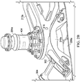
FIGS. 2A and2B , avibration suppression system 200 foraircraft 100 in accordance with one embodiment is shown along with a partial view offuselage 102 with an exposedroof 202. Thevibration suppression system 200 includes avibration isolation device 204, also referred to as a vibration isolation device or vibration eliminator, located in each corner in a four-corner pylon mount structural assembly. The combination of fourvibration isolation devices 204a-204d, two being forward of transmission or main rotor gearbox (MRGB) (not shown), and two being aft of the MRGB, collectively are effective at isolating main rotor vertical shear, pitch moment, as well as roll moment induced vibrations. For example, rotor hub induced pitch moment vibrations, which can become relatively large in high-speed forward flight, can be effectively isolated with the fourvibration isolation devices 204a-204d in the corner arrangement. - The
vibration suppression system 200 includes afirst roof beam 206a, asecond roof beam 206b, aforward cross member 208a, and anaft cross member 208b coupled to the airframe. Structural adapters can be used to structurally couplefirst roof beam 206a andsecond roof beam 206b withcross members first bipod mount 210a andsecond bipod mount 210b) are coupled to thefirst roof beam 206a, and bipod mounts 210c and 210d are coupled to thesecond roof beam 206b. Firstvibration isolation device 204a is coupled to thefirst bipod mount 210a using the mounting system described herein. Likewise, secondvibration isolation device 204b is coupled to thesecond bipod mount 210b, thirdvibration isolation device 204c is coupled to thethird bipod mount 210c, and fourthvibration isolation device 204d is coupled to thefourth bipod mount 210d, all using the mounting system described herein.First pylon structure 212a affixed to the MRGB is coupled to and extends between firstvibration isolation device 204a and secondvibration isolation device 204b. Similarly,second pylon structure 212b affixed to the MRGB is coupled to and extends between thirdvibration isolation device 204c and fourthvibration isolation device 204d. Eachvibration isolation device 204a-204d is mounted substantially vertical. It should be appreciated that embodiments ofvibration suppression system 200 may employ any practical number of engines and transmissions. Furthermore, it is contemplated that any plurality of pylon structures and vibration isolation devices may be used in a variety of orientations spaced fore, aft, and even inboard of the MRGB. -
Pylon structures isolation devices 204a-204d simultaneously by suspending a portion of MRGB between the plurality ofvibration isolation devices 204a-204d located on opposing ends of thepylon structures 212a-212b. The use ofpylon structures vibration isolation devices 204a-204d to an infinite number of locations independent of transmission or main rotor gearbox. Locatingvibration isolation devices 204a-204d forward and aft of MRGB minimizes the size of eachvibration isolation device 204a-204d and avoids the use of additional elements to control the dynamics of the MRGB. For example, thevibration suppression system 200 is springless in that thesystem 200 does not use a separate spring mounted externally beneath the MRGB to control dynamics of the MRGB. Thevibration suppression system 200 is configured to control pitch and roll dynamics by spacing ofvibration isolation devices 204a-204d and the use ofpylon structures clevis 302 that is used to mount the engine (not shown) viamember 304. - Further, implementing active vibration isolation devices, such as piezoelectric vibration isolation devices, can be effective for vibration isolation for a multiple RPM rotorcraft. It should be appreciated that other active actuation methods can be used as well, such as hydraulic, electromagnetic, electromechanical, magnetohydrodynamic, to name a few. Active vibration isolation devices can also achieve better vibration isolation by overcoming damping losses, and adjusting the frequency response characteristics. Further, each opposing pair of
vibration isolation devices 204a-204d can efficiently react against the moment oscillations because the moment can be decomposed into two antagonistic vertical oscillations at eachvibration isolation device 204. - Each
vibration isolation device 204a-204d includes anupper housing 404 and a lower housing 406 (not shown). A plurality of support struts 416 connects theupper housing 404 and thelower housing 406. It is desirable to integrate thestruts 416 into a vibration isolation device such that the struts can be removed and installed without damage to thevibration isolation devices 204a-204d. The present invention addresses this desirable feature. -
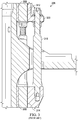
FIG. 3 shows a typical installation of the prior art. In such a prior art installation, integral threads ran throughfirst strut support 320, and strut 316 was held in place infirst strut support 320 by being screwed onto it. To removestrut 316, a load was applied to displace eitherelastomeric member 312 orelastomeric member 314, breaking the bond line between eitherelastomeric member 312 andpiston spindle 308, or betweenelastomeric member 314 andpiston spindle 308. Further, the prior artvibration isolation device 306 had to be placed in a fixture to apply a load that displaces eitherelastomeric member 312 orelastomeric member 314, enough to allow removal of thestrut 316, thus requiring a breaking of the bonding with thepiston spindle 308. -
FIG. 4A shows a cross-sectional view of avibration isolation device 204, including theupper housing 404 and thelower housing 406. In one non-limiting example, thevibration isolation device 204 can be a liquid inertia vibration eliminator (LIVE) system. A piston spindle 408 (also referred to as "spindle 408" herein) is at least partially disposed within the interior ofupper housing 404 andlower housing 406.Flange 409 ofpiston spindle 408 couples to thepylon structure elastomeric member 412 seals and resiliently contains thepiston spindle 408 within the interior ofupper housing 404. Similarly, a lowerelastomeric member 414 seals and resiliently locates thepiston spindle 408 within the interior oflower housing 406.Elastomeric members piston spindle 408 to move or oscillate relative to theupper housing 404 and thelower housing 406. When no load is applied,elastomeric members piston spindle 408 generally central toupper housing 404 andlower housing 406.Elastomeric members upper housing 404 and thelower housing 406.Elastomeric bearings spindle 408 with, e.g. a two-part room-temperature-curing epoxy adhesive or an elastomer-to-substrate adhesive such as a CHEMLOK® adhesive, and molded and adhered to thepiston spindle 408 during a vulcanization process or bonded using a post-vulcanization process. -
Upper housing 404 andlower housing 406 are coupled via support struts 416a, 416b. Shown herein are two struts, strut 416a and strut 416b, however,vibration isolation device 204 may have two or more struts 416. One skilled in the art will recognize thatvibration isolation device 204 may have 2, 3, 4, 5, 6, 7, 8 ormore struts First strut support 418 and firstremovable strut spindle 420 hold eachstrut upper housing 404, andsecond strut support 422 andsecond strut spindle 424 hold eachstrut 416 in place atlower housing 406. When installed,strut first strut spindle 420 andsecond strut spindle 424, without engagement (e.g., threaded or slotted engagement) of the first end to the first strut support or engagement (e.g., threaded or slotted engagement) of the second end to the second strut support. Such threated attachments and similar threaded attachments described herein may be sealed with a sealant, e.g., the anaerobic sealant LOCTITE®. - The present invention finds a particular advantage when a
strut 416 is damaged and needs to be replaced. The present invention permits removal ofstrut 412 without breaking the bond line betweenelastomeric member 412 andupper housing 404 or the bond line betweenelastomeric member 414 andlower housing 406. In this embodiment, the first removable spindle 420 (which can be, e.g., a bolt, spindle, peg, etc.), is removed or unscrewed and thestrut 416 is displaced in a lateral direction and removed or unscrewed from thesecond strut spindle 424. In a typical installation, thestrut 416 is provided with a shape that permits for the use of a wrench to unscrew thestrut 416 from thesecond strut spindle 424 without the need to break the bond line between theelastomeric bearings piston spindle 408 or the need to place the assembly in a fixture and applying load to displace the bearing. Thus, each of thestruts 416 can be replaced individually. The skilled artisan will recognize that thefirst strut spindle 420 andsecond strut spindle 424 can be threaded, slotted, or otherwise engaged in a manner that provides mechanical attachment between theupper housing 404 and thelower housing 406. Furthermore, in certain embodiments thestrut 416 has a shape or finish that in at least a portion of the longitudinal portion of the strut allows for the use of a wrench or other device to rotate thestrut 416. In one non-limiting example, the shaft portion of thestrut 416 may have one or more surfaces that form a polygonal shape or cross-section, e.g., square, rectangular, hexagonal, etc. In this embodiment, the firstremovable spindle 420 is disengaged, e.g., unscrewed, from thestrut 416 at theupper housing 404, which then allows for thestrut 416 to be disengaged, e.g., unscrewed, from thesecond strut spindle 424, and the upper portion thestrut 416 is laterally displaced for removal. Removal may be accomplished using a wrench that engages the hexagonal shape of the longitudinal portion of thestrut 416 to disengage, e.g., unscrew, thestrut 416 from thesecond strut spindle 424. When areplacement strut 416 is reinstalled, it may be necessary to provide a newsecond strut spindle 424. The firstremovable spindle 420 may be reused or replaced, depending on its condition. -
FIG. 4B depicts a detailed view the embodiment of the present invention shown inFIG. 4A . In this view, thestrut 416a,first strut spindle 420, andsecond strut spindle 424 are shown in place withpiston spindle 408,flange 409, pylon structure 212,first strut support 418, andsecond strut support 422. Also shown are first and secondelastomeric members -
FIG. 4C depicts a cross-sectional view of thevibration isolation device 450, which is similar tovibration isolation device 204 except that theremovable spindle 474 is found facing downward, which may find particular benefits. This embodiment of the invention works similarly to the embodiment illustrated inFIG. 4A .Vibration isolation device 450 includes first housing 454 (corresponding to the lower housing 404), second housing 456 (corresponding to the upper housing 404), firstelastomeric member 462, secondelastomeric member 464, struts 466a and 466b,first strut support 468,first strut spindle 470,second strut support 472, andsecond strut spindle 474. Also shown is flange 459 ofpiston spindle 458. In this embodiment, the second removable spindle 474 (bolt, spindle, peg, etc.) can be removed or disengaged, e.g., unscrewed. After removing the secondremovable spindle 474 thestrut 416 is displaced in a lateral direction and removed or disengaged, e.g., unscrewed from thefirst strut spindle 470. In a typical installation, thestrut 416 is provided with a shape that permits the use of a wrench to disengage, e.g., unscrew thestrut 416 from thefirst strut spindle 470 without the need to break the bond line between theelastomeric members spindle 458. Thus, each of thestruts 416 can be replaced individually. The skilled artisan will recognize that thefirst strut spindle 470 andsecond strut spindle 474 can be threaded, slotted, or otherwise engaged in a manner that provides mechanical attachment between theupper housing 404 and thelower housing 406. In one non-limiting example, the shaft portion of thestrut 416 may have a polygonal shape or cross-section, e.g., square, rectangular, hexagonal, etc. Furthermore, the skilled artisan will recognize that in certain embodiments both thefirst strut spindle 470 andsecond strut spindle 474 may be removable. -
FIG. 5 illustrates a method embodiment of the present invention.Method 500 of replacing a strut of a vibration isolation device includesblock 502, providing the vibration isolation device including a piston spindle; a first elastomeric member bonded to the piston spindle; a second elastomeric member bonded to the piston spindle; an upper housing in contact with the first elastomeric member; a lower housing in contact the second elastomeric member; a first strut support attached to or integral with the upper housing; a second strut support attached to or integral with the lower housing; and one or more struts removably configured to be engaged at a first end to the first strut spindle and at a second end to the second strut spindle, without engagement of the first end to the first strut support or engagement of the second end to the second strut support.Method 500 continues withblock 504, in which a first strut spindle is placed in the first strut support.Method 500 also includesblock 506, placing a second strut spindle in the second strut support.Block 508 ofmethod 500 includes engaging a first end of at least one of the one or more struts to the first strut spindle, and inblock 510, a second end of the at least one of the one or more struts is engaged to the second strut spindle; and inblock 512 removing the at least one of the one or more struts and installing a replacement strut without breaking a bonding of the first elastomeric member, the second elastomeric member, or both. -
FIG. 6 depicts another method embodiment of the present invention.Method 600 for removing a strut from a vibration isolation device includesblock 602, providing the vibration isolation device including a piston spindle; a first elastomeric member bonded to the piston spindle; a second elastomeric member bonded to the piston spindle; an upper housing in contact with the first elastomeric member; a lower housing in contact with the second elastomeric member; a first strut support attached to or integral with the upper housing; a second strut support attached to or integral with the lower housing; a first strut spindle configured to be placed in the first strut support; a second strut spindle configured to be placed in the second strut support; and one or more removable struts engaged at a first end to the first strut spindle and engaged at a second end to the second strut spindle, without engagement of the first end to the first strut support or engagement of the second end to the second strut support. Inblock 604, a load is applied to displace either the first elastomeric member or the second elastomeric member without breaking a bond of the first elastomeric member, the second elastomeric member, or both with the piston spindle. Inblock 606, the first end of the strut and the first strut spindle are disengaged or the second end of the strut and the second strut spindle are disengaged, without breaking a bond of the first elastomeric member, the second elastomeric member, or both with the piston spindle. Inblock 608 ofmethod 600, the strut is extracted from the vibration isolation device, again, without breaking a bond of the first elastomeric member, the second elastomeric member, or both with the piston spindle.
Claims (13)
- A strut assembly for a vibration isolation device (204) comprising:a piston spindle (408);a first elastomeric member (412) bonded to the piston spindle (408);a second elastomeric member (414) bonded to the piston spindle (408);an upper housing (404) in contact with the first elastomeric member (412);a lower housing (406) in contact with the second elastomeric member (414);a first strut support (418) attached to, or integral with, the upper housing (404);a second strut support (422) attached to, or integral with, the lower housing (406);a first strut spindle (420) configured to be placed in the first strut support (418);a second strut spindle (424) configured to be placed in the second strut support (422); andone or more removable struts (416) configured to be engaged at a first end to the first strut spindle (420) and at a second end to the second strut spindle (424), without engagement of the first end to the first strut support (418) or engagement of the second end to the second strut support (422), wherein at least one of the first or second strut spindles (420, 424) is removable such that the one or more struts (416) can be replaced without breaking a bonding of the first elastomeric member (412), the second elastomeric member (414), or both.
- The assembly of claim 1, wherein the first elastomeric member (412) is bonded to the piston spindle (408) or the second elastomeric member (414) is bonded to the piston spindle (408) using an elastomer-to-substrate adhesive, or wherein the first elastomeric member (412) or the second elastomeric member (414) is molded and adhered to the piston spindle (408) during a vulcanization process or bonded using a post-vulcanization process.
- The assembly of claim 1 or claim 2, wherein the one or more removable struts (416) is configured to be threaded or slotted at a first end to the first strut spindle (420) and configured to be threaded or slotted at a second end to the second strut spindle (424).
- A method of replacing a strut (416) of a vibration isolation device (204), the method comprising:providing the vibration isolation device (204) comprising:a piston spindle (408);a first elastomeric member (412) bonded to the piston spindle (408);a second elastomeric member (414) bonded to the piston spindle (408);an upper housing (404) in contact with the first elastomeric member (412);a lower housing (406) in contact with the second elastomeric member (414);a first strut support (418) attached to or integral with the upper housing (404);a second strut support (422) attached to or integral with the lower housing (406); andone or more struts (416) removably configured to be engaged at a first end to a first strut spindle (420) and at a second end to a second strut spindle (424), without engagement of the first end to the first strut support (418) or engagement of the second end to the second strut support (422);placing the first strut spindle (420) in the first strut support;placing the second strut spindle (424) in the second strut support;engaging a first end of at least one of the one or more struts (416) to the first strut spindle (420);engaging a second end of the at least one of the one or more struts (416) to the second strut spindle (424); andremoving the at least one of the one or more struts (416) and installing a replacement strut (416) without breaking a bonding of the first elastomeric member, the second elastomeric member (414), or both.
- The method of claim 4, wherein the first elastomeric member (412) is bonded to the piston spindle (408) or the second elastomeric member (414) is bonded to the piston spindle (408) using an elastomer-to-substrate adhesive, or wherein the first elastomeric member (412) or the second elastomeric member (414) is molded and adhered to the piston spindle (408) during a vulcanization process or bonded using a post-vulcanization process.
- The method of claim 4 or claim 5, wherein the strut (416) is threaded or slotted at a first end to the first strut spindle (420) and threaded or slotted at a second end to the second strut spindle (424).
- A method of removing a strut (416) from a vibration isolation device (204), the method comprising:
providing the vibration isolation device (204) comprising:a piston spindle (408);a first elastomeric member (412) bonded to the piston spindle (408);a second elastomeric member (414) bonded to the piston spindle (408);an upper housing (404) in contact with the first elastomeric member (412);a lower housing (406) in contact with the second elastomeric member (414);a first strut support (418) attached to or integral with the upper housing (404);a second strut support (422) attached to or integral with the lower housing (406);a first strut spindle (420) configured to be placed in the first strut support (418);a second strut spindle (424) configured to be placed in the second strut support (422); andone or more removable struts (416) engaged at a first end to the first strut spindle (420) and engaged at a second end to the second strut spindle (424), without engagement of the first end to the first strut support (418) or engagement of the second end to the second strut support (422);applying a load to displace either the first elastomeric member (412) or the second elastomeric member (414) without breaking a bond of the first elastomeric member (412), the second elastomeric member (414), or both with the piston spindle (408);disengaging the first end of the strut (416) and the first strut spindle (420) or disengaging the second end of the strut (416) and the second strut spindle (424), without breaking a bonding of the first elastomeric member (412), the second elastomeric member (414), or both with the piston spindle (408); andextracting the strut (416) from the vibration isolation device (204) without breaking the bond of the first elastomeric member (412), the second elastomeric member (414), or both with the piston spindle (408). - The method of claim 7, wherein the first elastomeric member (412) is bonded to the piston spindle (408) or the second elastomeric member (414) is bonded to the piston spindle (408) using an elastomer-to-substrate adhesive, or wherein the first elastomeric member (412) or the second elastomeric member (414) is molded and adhered to the piston spindle (408) during a vulcanization process or bonded using a post-vulcanization process.
- The method of claim 7 or claim 8, wherein the strut (416) is threaded or slotted at a first end to the first strut spindle (420) and threaded or slotted at a second end to the second strut spindle (424).
- The assembly of any preceding assembly claim, wherein the first elastomeric member (412) or the second elastomeric member (414) comprises rubber, plastics, composites, or layered materials.
- The method of any preceding method claim, wherein the first elastomeric member (412) or the second elastomeric member (414) comprises rubber, plastics, composites, or layered materials.
- The assembly of any preceding assembly claim, wherein the one or more removable struts (416) further comprise one or more surfaces on at least a portion of the strut to be engaged by a wrench.
- The method of any preceding method claim, wherein the one or more removable struts (416) further comprise one or more surfaces on at least a portion of the strut to be engaged by a wrench.
Applications Claiming Priority (1)
| Application Number | Priority Date | Filing Date | Title |
|---|---|---|---|
| US16/019,826 US10967962B2 (en) | 2018-06-27 | 2018-06-27 | Removable struts for vibration isolation device mounting system |
Publications (2)
| Publication Number | Publication Date |
|---|---|
| EP3587257A1 EP3587257A1 (en) | 2020-01-01 |
| EP3587257B1 true EP3587257B1 (en) | 2021-04-28 |
Family
ID=63244487
Family Applications (1)
| Application Number | Title | Priority Date | Filing Date |
|---|---|---|---|
| EP18188732.4A Active EP3587257B1 (en) | 2018-06-27 | 2018-08-13 | Removable struts for vibration isolation device mounting system |
Country Status (2)
| Country | Link |
|---|---|
| US (2) | US10967962B2 (en) |
| EP (1) | EP3587257B1 (en) |
Families Citing this family (2)
| Publication number | Priority date | Publication date | Assignee | Title |
|---|---|---|---|---|
| US10967962B2 (en) | 2018-06-27 | 2021-04-06 | Bell Helicopter Textron Inc. | Removable struts for vibration isolation device mounting system |
| US11787550B1 (en) | 2022-05-04 | 2023-10-17 | Beta Air, Llc | Propulsor assembly powered by a dual motor system |
Family Cites Families (11)
| Publication number | Priority date | Publication date | Assignee | Title |
|---|---|---|---|---|
| CA2182275C (en) | 1994-12-01 | 2005-09-20 | Michael Reaugh Smith | Vibration isolation system |
| US5788372A (en) * | 1996-05-10 | 1998-08-04 | Lord Corporation | Method and apparatus for reducing transient motion between an aircraft power member and structure during takeoff, landing and maneuvers |
| US6715746B2 (en) * | 2000-07-21 | 2004-04-06 | Lord Corporation | Vibration isolation device with load dependent stiffness |
| US6695106B2 (en) | 2000-09-26 | 2004-02-24 | Bell Helicopter Textron, Inc. | Method and apparatus for improved vibration isolation |
| US6484341B2 (en) | 2001-02-28 | 2002-11-26 | The Pampered Chef, Ltd. | Dough roller |
| US20130161884A1 (en) * | 2011-12-26 | 2013-06-27 | Bell Helicopter Textron Inc. | System and Method of Tuning a Liquid Inertia Vibration Eliminator |
| US8672262B2 (en) | 2012-01-10 | 2014-03-18 | Textron Innovations Inc. | Mechanically optimized liquid inertia vibration eliminator and aircraft pylon system |
| US9777788B2 (en) * | 2012-01-10 | 2017-10-03 | Bell Helicopter Textron Inc. | Rotorcraft vibration suppression system in a four corner pylon mount configuration |
| US9279741B2 (en) | 2012-11-30 | 2016-03-08 | Corning Incorporated | Method of measuring multi-mode fiber optical properties during processing of the fiber |
| US10703465B2 (en) * | 2018-03-30 | 2020-07-07 | Bell Helicopter Textron Inc. | Vibration isolation device mounting system |
| US10967962B2 (en) | 2018-06-27 | 2021-04-06 | Bell Helicopter Textron Inc. | Removable struts for vibration isolation device mounting system |
-
2018
- 2018-06-27 US US16/019,826 patent/US10967962B2/en active Active
- 2018-08-13 EP EP18188732.4A patent/EP3587257B1/en active Active
-
2021
- 2021-02-26 US US17/186,484 patent/US11485484B2/en active Active
Non-Patent Citations (1)
| Title |
|---|
| None * |
Also Published As
| Publication number | Publication date |
|---|---|
| EP3587257A1 (en) | 2020-01-01 |
| US20200001986A1 (en) | 2020-01-02 |
| US11485484B2 (en) | 2022-11-01 |
| US10967962B2 (en) | 2021-04-06 |
| US20210179262A1 (en) | 2021-06-17 |
Similar Documents
| Publication | Publication Date | Title |
|---|---|---|
| US10330166B2 (en) | Rotorcraft vibration suppression system in a four corner pylon mount configuration | |
| US10703465B2 (en) | Vibration isolation device mounting system | |
| US8672262B2 (en) | Mechanically optimized liquid inertia vibration eliminator and aircraft pylon system | |
| EP2182239B1 (en) | Piezoelectric liquid inertia vibration eliminator | |
| CA2704734C (en) | Method and apparatus for improved vibration isolation | |
| EP2673530B1 (en) | Pylon mounting system with vibration isolation | |
| US11485484B2 (en) | Removable struts for vibration isolation device mounting system | |
| US9249856B1 (en) | Liquid inertia vibration mount | |
| JPS6249239B2 (en) | ||
| EP2367719B1 (en) | Tail rotor blade assembly and elastomeric bearing system motion limiter | |
| US20070108340A1 (en) | Vibration isolation system | |
| EP2610172B1 (en) | System and method of tuning a liquid inertia vibration eliminator | |
| US10994834B2 (en) | Case mounted transmission AVC force generators | |
| US20160176519A1 (en) | Flow restriction system for regulating dynamic pressure loss |
Legal Events
| Date | Code | Title | Description |
|---|---|---|---|
| PUAI | Public reference made under article 153(3) epc to a published international application that has entered the european phase |
Free format text: ORIGINAL CODE: 0009012 |
|
| STAA | Information on the status of an ep patent application or granted ep patent |
Free format text: STATUS: REQUEST FOR EXAMINATION WAS MADE |
|
| 17P | Request for examination filed |
Effective date: 20180813 |
|
| AK | Designated contracting states |
Kind code of ref document: A1 Designated state(s): AL AT BE BG CH CY CZ DE DK EE ES FI FR GB GR HR HU IE IS IT LI LT LU LV MC MK MT NL NO PL PT RO RS SE SI SK SM TR |
|
| AX | Request for extension of the european patent |
Extension state: BA ME |
|
| STAA | Information on the status of an ep patent application or granted ep patent |
Free format text: STATUS: EXAMINATION IS IN PROGRESS |
|
| 17Q | First examination report despatched |
Effective date: 20200417 |
|
| GRAP | Despatch of communication of intention to grant a patent |
Free format text: ORIGINAL CODE: EPIDOSNIGR1 |
|
| STAA | Information on the status of an ep patent application or granted ep patent |
Free format text: STATUS: GRANT OF PATENT IS INTENDED |
|
| INTG | Intention to grant announced |
Effective date: 20201201 |
|
| GRAJ | Information related to disapproval of communication of intention to grant by the applicant or resumption of examination proceedings by the epo deleted |
Free format text: ORIGINAL CODE: EPIDOSDIGR1 |
|
| STAA | Information on the status of an ep patent application or granted ep patent |
Free format text: STATUS: EXAMINATION IS IN PROGRESS |
|
| INTC | Intention to grant announced (deleted) | ||
| GRAP | Despatch of communication of intention to grant a patent |
Free format text: ORIGINAL CODE: EPIDOSNIGR1 |
|
| STAA | Information on the status of an ep patent application or granted ep patent |
Free format text: STATUS: GRANT OF PATENT IS INTENDED |
|
| GRAS | Grant fee paid |
Free format text: ORIGINAL CODE: EPIDOSNIGR3 |
|
| GRAA | (expected) grant |
Free format text: ORIGINAL CODE: 0009210 |
|
| STAA | Information on the status of an ep patent application or granted ep patent |
Free format text: STATUS: THE PATENT HAS BEEN GRANTED |
|
| INTG | Intention to grant announced |
Effective date: 20210304 |
|
| AK | Designated contracting states |
Kind code of ref document: B1 Designated state(s): AL AT BE BG CH CY CZ DE DK EE ES FI FR GB GR HR HU IE IS IT LI LT LU LV MC MK MT NL NO PL PT RO RS SE SI SK SM TR |
|
| REG | Reference to a national code |
Ref country code: GB Ref legal event code: FG4D |
|
| REG | Reference to a national code |
Ref country code: CH Ref legal event code: EP |
|
| REG | Reference to a national code |
Ref country code: AT Ref legal event code: REF Ref document number: 1386789 Country of ref document: AT Kind code of ref document: T Effective date: 20210515 |
|
| REG | Reference to a national code |
Ref country code: DE Ref legal event code: R096 Ref document number: 602018016103 Country of ref document: DE |
|
| REG | Reference to a national code |
Ref country code: IE Ref legal event code: FG4D |
|
| REG | Reference to a national code |
Ref country code: LT Ref legal event code: MG9D |
|
| REG | Reference to a national code |
Ref country code: AT Ref legal event code: MK05 Ref document number: 1386789 Country of ref document: AT Kind code of ref document: T Effective date: 20210428 |
|
| PG25 | Lapsed in a contracting state [announced via postgrant information from national office to epo] |
Ref country code: HR Free format text: LAPSE BECAUSE OF FAILURE TO SUBMIT A TRANSLATION OF THE DESCRIPTION OR TO PAY THE FEE WITHIN THE PRESCRIBED TIME-LIMIT Effective date: 20210428 Ref country code: LT Free format text: LAPSE BECAUSE OF FAILURE TO SUBMIT A TRANSLATION OF THE DESCRIPTION OR TO PAY THE FEE WITHIN THE PRESCRIBED TIME-LIMIT Effective date: 20210428 Ref country code: FI Free format text: LAPSE BECAUSE OF FAILURE TO SUBMIT A TRANSLATION OF THE DESCRIPTION OR TO PAY THE FEE WITHIN THE PRESCRIBED TIME-LIMIT Effective date: 20210428 Ref country code: AT Free format text: LAPSE BECAUSE OF FAILURE TO SUBMIT A TRANSLATION OF THE DESCRIPTION OR TO PAY THE FEE WITHIN THE PRESCRIBED TIME-LIMIT Effective date: 20210428 Ref country code: BG Free format text: LAPSE BECAUSE OF FAILURE TO SUBMIT A TRANSLATION OF THE DESCRIPTION OR TO PAY THE FEE WITHIN THE PRESCRIBED TIME-LIMIT Effective date: 20210728 Ref country code: NL Free format text: LAPSE BECAUSE OF FAILURE TO SUBMIT A TRANSLATION OF THE DESCRIPTION OR TO PAY THE FEE WITHIN THE PRESCRIBED TIME-LIMIT Effective date: 20210428 |
|
| PG25 | Lapsed in a contracting state [announced via postgrant information from national office to epo] |
Ref country code: PT Free format text: LAPSE BECAUSE OF FAILURE TO SUBMIT A TRANSLATION OF THE DESCRIPTION OR TO PAY THE FEE WITHIN THE PRESCRIBED TIME-LIMIT Effective date: 20210830 Ref country code: NO Free format text: LAPSE BECAUSE OF FAILURE TO SUBMIT A TRANSLATION OF THE DESCRIPTION OR TO PAY THE FEE WITHIN THE PRESCRIBED TIME-LIMIT Effective date: 20210728 Ref country code: PL Free format text: LAPSE BECAUSE OF FAILURE TO SUBMIT A TRANSLATION OF THE DESCRIPTION OR TO PAY THE FEE WITHIN THE PRESCRIBED TIME-LIMIT Effective date: 20210428 Ref country code: LV Free format text: LAPSE BECAUSE OF FAILURE TO SUBMIT A TRANSLATION OF THE DESCRIPTION OR TO PAY THE FEE WITHIN THE PRESCRIBED TIME-LIMIT Effective date: 20210428 Ref country code: RS Free format text: LAPSE BECAUSE OF FAILURE TO SUBMIT A TRANSLATION OF THE DESCRIPTION OR TO PAY THE FEE WITHIN THE PRESCRIBED TIME-LIMIT Effective date: 20210428 Ref country code: SE Free format text: LAPSE BECAUSE OF FAILURE TO SUBMIT A TRANSLATION OF THE DESCRIPTION OR TO PAY THE FEE WITHIN THE PRESCRIBED TIME-LIMIT Effective date: 20210428 Ref country code: GR Free format text: LAPSE BECAUSE OF FAILURE TO SUBMIT A TRANSLATION OF THE DESCRIPTION OR TO PAY THE FEE WITHIN THE PRESCRIBED TIME-LIMIT Effective date: 20210729 Ref country code: IS Free format text: LAPSE BECAUSE OF FAILURE TO SUBMIT A TRANSLATION OF THE DESCRIPTION OR TO PAY THE FEE WITHIN THE PRESCRIBED TIME-LIMIT Effective date: 20210828 |
|
| REG | Reference to a national code |
Ref country code: NL Ref legal event code: MP Effective date: 20210428 |
|
| PG25 | Lapsed in a contracting state [announced via postgrant information from national office to epo] |
Ref country code: DK Free format text: LAPSE BECAUSE OF FAILURE TO SUBMIT A TRANSLATION OF THE DESCRIPTION OR TO PAY THE FEE WITHIN THE PRESCRIBED TIME-LIMIT Effective date: 20210428 Ref country code: CZ Free format text: LAPSE BECAUSE OF FAILURE TO SUBMIT A TRANSLATION OF THE DESCRIPTION OR TO PAY THE FEE WITHIN THE PRESCRIBED TIME-LIMIT Effective date: 20210428 Ref country code: RO Free format text: LAPSE BECAUSE OF FAILURE TO SUBMIT A TRANSLATION OF THE DESCRIPTION OR TO PAY THE FEE WITHIN THE PRESCRIBED TIME-LIMIT Effective date: 20210428 Ref country code: EE Free format text: LAPSE BECAUSE OF FAILURE TO SUBMIT A TRANSLATION OF THE DESCRIPTION OR TO PAY THE FEE WITHIN THE PRESCRIBED TIME-LIMIT Effective date: 20210428 Ref country code: ES Free format text: LAPSE BECAUSE OF FAILURE TO SUBMIT A TRANSLATION OF THE DESCRIPTION OR TO PAY THE FEE WITHIN THE PRESCRIBED TIME-LIMIT Effective date: 20210428 Ref country code: SK Free format text: LAPSE BECAUSE OF FAILURE TO SUBMIT A TRANSLATION OF THE DESCRIPTION OR TO PAY THE FEE WITHIN THE PRESCRIBED TIME-LIMIT Effective date: 20210428 Ref country code: SM Free format text: LAPSE BECAUSE OF FAILURE TO SUBMIT A TRANSLATION OF THE DESCRIPTION OR TO PAY THE FEE WITHIN THE PRESCRIBED TIME-LIMIT Effective date: 20210428 |
|
| REG | Reference to a national code |
Ref country code: DE Ref legal event code: R097 Ref document number: 602018016103 Country of ref document: DE |
|
| PLBE | No opposition filed within time limit |
Free format text: ORIGINAL CODE: 0009261 |
|
| STAA | Information on the status of an ep patent application or granted ep patent |
Free format text: STATUS: NO OPPOSITION FILED WITHIN TIME LIMIT |
|
| REG | Reference to a national code |
Ref country code: CH Ref legal event code: PL |
|
| PG25 | Lapsed in a contracting state [announced via postgrant information from national office to epo] |
Ref country code: MC Free format text: LAPSE BECAUSE OF FAILURE TO SUBMIT A TRANSLATION OF THE DESCRIPTION OR TO PAY THE FEE WITHIN THE PRESCRIBED TIME-LIMIT Effective date: 20210428 |
|
| 26N | No opposition filed |
Effective date: 20220131 |
|
| REG | Reference to a national code |
Ref country code: BE Ref legal event code: MM Effective date: 20210831 |
|
| PG25 | Lapsed in a contracting state [announced via postgrant information from national office to epo] |
Ref country code: LI Free format text: LAPSE BECAUSE OF NON-PAYMENT OF DUE FEES Effective date: 20210831 Ref country code: CH Free format text: LAPSE BECAUSE OF NON-PAYMENT OF DUE FEES Effective date: 20210831 |
|
| PG25 | Lapsed in a contracting state [announced via postgrant information from national office to epo] |
Ref country code: IS Free format text: LAPSE BECAUSE OF FAILURE TO SUBMIT A TRANSLATION OF THE DESCRIPTION OR TO PAY THE FEE WITHIN THE PRESCRIBED TIME-LIMIT Effective date: 20210828 Ref country code: LU Free format text: LAPSE BECAUSE OF NON-PAYMENT OF DUE FEES Effective date: 20210813 Ref country code: AL Free format text: LAPSE BECAUSE OF FAILURE TO SUBMIT A TRANSLATION OF THE DESCRIPTION OR TO PAY THE FEE WITHIN THE PRESCRIBED TIME-LIMIT Effective date: 20210428 |
|
| PG25 | Lapsed in a contracting state [announced via postgrant information from national office to epo] |
Ref country code: IE Free format text: LAPSE BECAUSE OF NON-PAYMENT OF DUE FEES Effective date: 20210813 Ref country code: BE Free format text: LAPSE BECAUSE OF NON-PAYMENT OF DUE FEES Effective date: 20210831 |
|
| PG25 | Lapsed in a contracting state [announced via postgrant information from national office to epo] |
Ref country code: CY Free format text: LAPSE BECAUSE OF FAILURE TO SUBMIT A TRANSLATION OF THE DESCRIPTION OR TO PAY THE FEE WITHIN THE PRESCRIBED TIME-LIMIT Effective date: 20210428 |
|
| P01 | Opt-out of the competence of the unified patent court (upc) registered |
Effective date: 20230602 |
|
| PG25 | Lapsed in a contracting state [announced via postgrant information from national office to epo] |
Ref country code: HU Free format text: LAPSE BECAUSE OF FAILURE TO SUBMIT A TRANSLATION OF THE DESCRIPTION OR TO PAY THE FEE WITHIN THE PRESCRIBED TIME-LIMIT; INVALID AB INITIO Effective date: 20180813 |
|
| PG25 | Lapsed in a contracting state [announced via postgrant information from national office to epo] |
Ref country code: MK Free format text: LAPSE BECAUSE OF FAILURE TO SUBMIT A TRANSLATION OF THE DESCRIPTION OR TO PAY THE FEE WITHIN THE PRESCRIBED TIME-LIMIT Effective date: 20210428 |
|
| PG25 | Lapsed in a contracting state [announced via postgrant information from national office to epo] |
Ref country code: TR Free format text: LAPSE BECAUSE OF FAILURE TO SUBMIT A TRANSLATION OF THE DESCRIPTION OR TO PAY THE FEE WITHIN THE PRESCRIBED TIME-LIMIT Effective date: 20210428 |
|
| PG25 | Lapsed in a contracting state [announced via postgrant information from national office to epo] |
Ref country code: MT Free format text: LAPSE BECAUSE OF FAILURE TO SUBMIT A TRANSLATION OF THE DESCRIPTION OR TO PAY THE FEE WITHIN THE PRESCRIBED TIME-LIMIT Effective date: 20210428 |
|
| PGFP | Annual fee paid to national office [announced via postgrant information from national office to epo] |
Ref country code: DE Payment date: 20250827 Year of fee payment: 8 |
|
| PGFP | Annual fee paid to national office [announced via postgrant information from national office to epo] |
Ref country code: IT Payment date: 20250820 Year of fee payment: 8 |
|
| PGFP | Annual fee paid to national office [announced via postgrant information from national office to epo] |
Ref country code: GB Payment date: 20250827 Year of fee payment: 8 |
|
| PGFP | Annual fee paid to national office [announced via postgrant information from national office to epo] |
Ref country code: FR Payment date: 20250825 Year of fee payment: 8 |