EP3587129A1 - Recording apparatus - Google Patents
Recording apparatus Download PDFInfo
- Publication number
- EP3587129A1 EP3587129A1 EP19182171.9A EP19182171A EP3587129A1 EP 3587129 A1 EP3587129 A1 EP 3587129A1 EP 19182171 A EP19182171 A EP 19182171A EP 3587129 A1 EP3587129 A1 EP 3587129A1
- Authority
- EP
- European Patent Office
- Prior art keywords
- charging
- adsorption surface
- medium
- recording
- contact
- Prior art date
- Legal status (The legal status is an assumption and is not a legal conclusion. Google has not performed a legal analysis and makes no representation as to the accuracy of the status listed.)
- Granted
Links
Images



Classifications
-
- B—PERFORMING OPERATIONS; TRANSPORTING
- B41—PRINTING; LINING MACHINES; TYPEWRITERS; STAMPS
- B41J—TYPEWRITERS; SELECTIVE PRINTING MECHANISMS, i.e. MECHANISMS PRINTING OTHERWISE THAN FROM A FORME; CORRECTION OF TYPOGRAPHICAL ERRORS
- B41J13/00—Devices or arrangements of selective printing mechanisms, e.g. ink-jet printers or thermal printers, specially adapted for supporting or handling copy material in short lengths, e.g. sheets
- B41J13/08—Conveyor bands or like feeding devices
-
- B—PERFORMING OPERATIONS; TRANSPORTING
- B41—PRINTING; LINING MACHINES; TYPEWRITERS; STAMPS
- B41J—TYPEWRITERS; SELECTIVE PRINTING MECHANISMS, i.e. MECHANISMS PRINTING OTHERWISE THAN FROM A FORME; CORRECTION OF TYPOGRAPHICAL ERRORS
- B41J11/00—Devices or arrangements of selective printing mechanisms, e.g. ink-jet printers or thermal printers, for supporting or handling copy material in sheet or web form
- B41J11/007—Conveyor belts or like feeding devices
-
- B—PERFORMING OPERATIONS; TRANSPORTING
- B41—PRINTING; LINING MACHINES; TYPEWRITERS; STAMPS
- B41J—TYPEWRITERS; SELECTIVE PRINTING MECHANISMS, i.e. MECHANISMS PRINTING OTHERWISE THAN FROM A FORME; CORRECTION OF TYPOGRAPHICAL ERRORS
- B41J2/00—Typewriters or selective printing mechanisms characterised by the printing or marking process for which they are designed
- B41J2/005—Typewriters or selective printing mechanisms characterised by the printing or marking process for which they are designed characterised by bringing liquid or particles selectively into contact with a printing material
- B41J2/01—Ink jet
-
- B—PERFORMING OPERATIONS; TRANSPORTING
- B41—PRINTING; LINING MACHINES; TYPEWRITERS; STAMPS
- B41J—TYPEWRITERS; SELECTIVE PRINTING MECHANISMS, i.e. MECHANISMS PRINTING OTHERWISE THAN FROM A FORME; CORRECTION OF TYPOGRAPHICAL ERRORS
- B41J11/00—Devices or arrangements of selective printing mechanisms, e.g. ink-jet printers or thermal printers, for supporting or handling copy material in sheet or web form
- B41J11/0095—Detecting means for copy material, e.g. for detecting or sensing presence of copy material or its leading or trailing end
-
- B—PERFORMING OPERATIONS; TRANSPORTING
- B41—PRINTING; LINING MACHINES; TYPEWRITERS; STAMPS
- B41J—TYPEWRITERS; SELECTIVE PRINTING MECHANISMS, i.e. MECHANISMS PRINTING OTHERWISE THAN FROM A FORME; CORRECTION OF TYPOGRAPHICAL ERRORS
- B41J29/00—Details of, or accessories for, typewriters or selective printing mechanisms not otherwise provided for
-
- B—PERFORMING OPERATIONS; TRANSPORTING
- B65—CONVEYING; PACKING; STORING; HANDLING THIN OR FILAMENTARY MATERIAL
- B65H—HANDLING THIN OR FILAMENTARY MATERIAL, e.g. SHEETS, WEBS, CABLES
- B65H2404/00—Parts for transporting or guiding the handled material
- B65H2404/20—Belts
Definitions
- the present disclosure relates to a recording apparatus that performs recording on a medium.
- a configuration may be adopted in which a medium represented by a recording paper sheet is transported using a transport belt. Further, in this configuration, the medium may be adsorbed to the transport belt by charging the transport belt (see JP-A-2006-27771 ).
- Ozone may be generated while the transport belt is charged, and a filter may be provided to prevent leakage of the ozone to the outside of the apparatus, depending on the amount of generated ozone.
- defect caused by the ozone inside the apparatus is not particularly considered, and for example, there is a possibility that a water-repellent film on a surface of the recording head is contaminated by the ozone, and ink ejection failure occurs.
- the transport belt is charged, there is a possibility that the ink is drawn from a nozzle of the recording head disposed to face the charged transport belt, the drawn ink is thickened, and thus ink ejection failure occurs.
- a recording apparatus includes a recording head that performs recording on a medium, a transport belt that has an adsorption surface that adsorbs the medium, and transports the medium to a position facing the recording head, a first charging unit that is in contact with the transport belt to frictionally charge the adsorption surface, a second charging unit that applies a voltage to the transport belt to charge the adsorption surface, and a control unit that controls the first charging unit and the second charging unit, in which the control unit switches between the charging of the adsorption surface by the first charging unit and the charging of the adsorption surface by the second charging unit, according to a state of a surface of the medium, which is in contact with the adsorption surface.
- a recording apparatus includes a recording head that performs recording on a medium, a transport belt that has an adsorption surface that adsorbs the medium, and transports the medium to a position facing the recording head, a first charging unit that is in contact with the transport belt to frictionally charge the adsorption surface, a second charging unit that applies a voltage to the transport belt to charge the adsorption surface, and a control unit that switches between charging of the adsorption surface by the first charging unit and charging of the adsorption surface by the second charging unit, in which the control unit switches between the charging of the adsorption surface by the first charging unit and the charging of the adsorption surface by the second charging unit, according to a state of a surface of the medium, which is in contact with the adsorption surface.
- the recording apparatus includes the first charging unit that is in contact with the transport belt to frictionally charge the adsorption surface that adsorbs the medium, and the second charging unit that applies a voltage to the transport belt to charge the adsorption surface. Since the control unit switches between the charging of the adsorption surface by the first charging unit and the charging of the adsorption surface by the second charging unit according to the state of the surface of the medium, which is in contact with the adsorption surface, the charging of the adsorption surface by the second charging unit is minimized, so that both suppression of the amount of generated ozone and proper adsorption of the medium to the adsorption surface are achieved. Further, as the first charging unit is selected, power consumption can be suppressed.
- control unit switches between the charging of the adsorption surface by the first charging unit and the charging of the adsorption surface by the second charging unit according to the state of the surface of the medium, which is in contact with the adsorption surface, according to the transport belt, a period during which the charging is performed by the second charging unit that performs stronger charging can be reduced, and an increase in viscosity of the ink caused by pulling out an ink from a nozzle of the recording head can be suppressed.
- the control unit determines whether or not recording is performed on a surface adsorbed to the adsorption surface as a state of the surface of the medium, selects the charging of the adsorption surface by the first charging unit when the surface of the medium on which the recording is not performed is adsorbed to the adsorption surface, and selects the charging of the adsorption surface by the second charging unit when the surface of the medium on which the recording is already performed is adsorbed to the adsorption surface.
- the latter when recording is performed by ejecting a liquid to the medium, on a surface of the medium to which the liquid is ejected, that is, the surface of the medium on which the recording is already performed, and a surface of the medium to which the liquid is not ejected, that is, the surface of the medium on which the recording is not performed, the latter, that is, the surface of the medium on which the recording is not performed, has low electric conductivity, and is adsorbed to the adsorption surface well.
- control unit selects the charging of the adsorption surface by the first charging unit when the surface of the medium on which the recording is not performed is adsorbed to the adsorption surface, and selects the charging of the adsorption surface by the second charging unit when the surface of the medium on which the recording is already performed is adsorbed to the adsorption surface, both when the surface of the medium on which the recording is already performed is adsorbed and when the surface of the medium on which the recording is not performed is adsorbed, the medium can be properly adsorbed.
- the charging of the adsorption surface by the second charging unit is configured to be switched between charging by application of a first voltage and charging by application of a second voltage that is less than the first voltage, and when the charging of the adsorption surface by the second charging unit is selected, the control unit selects the first voltage in a contact area of the adsorption surface, which is in contact with the medium, and selects the second voltage in a non-contact area of the adsorption surface, which is not in contact with the medium.
- the control unit selects the first voltage in the contact area of the adsorption surface, which is in contact with the medium, and selects the second voltage that is lower than the first voltage in the non-contact area of the adsorption surface, which is not in contact with the medium, the amount of generated ozone when the second charging unit is selected can be suppressed.
- the second voltage includes 0 V.
- the charging of the adsorption surface by the second charging unit is configured to be switched between charging by application of a first voltage and charging by application of a second voltage that is less than the first voltage, and when the charging of the adsorption surface by the second charging unit is selected, the control unit selects the first voltage in an area of the adsorption surface which is in contact with a leading end and a trailing end of the medium and selects the second voltage in an area of the adsorption surface, which is in contact with an intermediate portion between the leading end and the trailing end of the medium.
- the control unit selects the first voltage in the area of the adsorption surface that is in contact with the leading end and the trailing end of the medium, and selects the second voltage that is lower than the first voltage in the area of the adsorption surface, which is in contact with the intermediate portion between the leading end and the trailing end of the medium, floating from the adsorption surface can be satisfactorily suppressed by selecting the first voltage in the leading end and the trailing end of the medium, and the amount of the generated ozone can be suppressed by selecting the second voltage in the area which is in contact with the intermediate portion between the leading end and the trailing end of the medium.
- the second voltage includes 0 V.
- the control unit determines a recording density of a surface adsorbed to the adsorption surface as a state of the surface of the medium, and switches between the first charging unit and the second charging unit according to the recording density of the surface of the medium, which is in contact with the adsorption surface.
- control unit selects the charging of the adsorption surface by the first charging unit when the recording density of the surface of the medium, which is in contact with the adsorption surface, is low, and selects the charging of the adsorption surface by the second charging unit when the recording density of the surface of the medium, which is in contact with the adsorption surface, is high.
- control unit switches between the first charging unit and the second charging unit according to the recording density of the surface of the medium, which is in contact with the adsorption surface, both suppression of the amount of generated ozone and proper adsorption of the medium to the adsorption surface can be achieved.
- the control unit determines a recording position of the medium in a transport direction on a surface adsorbed to the adsorption surface as a state of the surface of the medium, and switches between the first charging unit and the second charging unit along the transport direction according to a recording position of the medium in the transport direction on the surface of the medium, which is in contact with the adsorption surface.
- control unit selects the charging of the adsorption surface by the first charging unit in an intermediate area of the medium in the transport direction on the surface of the medium, which is in contact with the adsorption surface, and selects the charging of the adsorption surface by the second charging unit in an end portion area of the medium in the transport direction on the surface of the medium, which is in contact with the adsorption surface.
- control unit since the control unit switches between the first charging unit and the second charging unit along the transport direction according to a recording position of the medium in the transport direction on the surface of the medium, which is in contact with the adsorption surface, both suppression of the amount of generated ozone and proper adsorption of the medium to the adsorption surface can be achieved.
- the first charging unit and the second charging unit charge the adsorption surface to have a positive polarity.
- the recording apparatus further includes a charge removing brush that is configured to come into contact with the adsorption surface, and a switching unit that switches whether or not the charge removing brush is grounded, in which the first charging unit is configured with the not-grounded charge removing brush.
- the charge removing brush which is a configuration for removing charges, also serves as the first charging unit, an increase in costs can be suppressed by reducing the number of components.
- an ink jet printer (hereinafter, referred to as a "printer") that performs ink jet recording on a recording paper sheet that is an example of a medium is described as an example of a recording apparatus according to the present disclosure.
- the present disclosure may be applied even to any form such as a type in which an ink cartridge is mounted on a carriage and a type in which an ink containing portion is provided outside a carriage and the ink containing portion and the carriage are connected to each other using an ink tube.
- a printer 1 according to the present embodiment is of a type in which an ink containing portion is provided outside a carriage and the ink containing portion and the carriage are connected to each other through an ink tube.
- a recording head that ejects an ink is of a type in which the recording head moves in a paper sheet width direction and a type in which the recording head is formed to have a size that covers the paper sheet width direction and does not move.
- the printer 1 according to the present embodiment corresponds to the latter type.
- an x direction indicates a device depth direction and the paper sheet width direction
- a y direction indicates a device width direction
- a z direction indicates a device height direction and a gravity direction.
- a direction in which the recording paper sheet is transported is referred to as "downstream”
- a direction that is opposite thereto is referred to as "upstream”.
- the printer 1 includes a scanner unit 3 on a main device body 2A that performs recording on the recording paper sheet, and includes extension units 2B and 2C under the main device body 2A.
- the main device body 2A includes a paper sheet cassette 10A
- the extension unit 2B includes a paper sheet cassette 10B
- the extension unit 2C includes a paper sheet cassette 10C.
- These extension units 2B and 2C are optional units for increasing the number of sheets accommodated therein, and are optionally attached to the main device body 2A.
- Reference numeral 5 denotes an operation unit that performs various operations of the printer 1
- reference numeral 4 denotes a tray for receiving the recording paper sheet to be discharged after recording, and more particularly, a face-down paper discharge tray for receiving the recording paper sheet discharged while a recording surface on which the recording is recently performed is directed to the lower side.
- reference numeral 35 denotes a feeding unit, which can be opened and closed with respect to the main device body 2A as the feeding unit pivots about a not-illustrated pivoting point.
- Reference numeral 6 denotes an opening and closing cover constituting the feeding unit 35, which can rotate about a rotary shaft 6a (see FIG. 2 ) and can be opened and closed in a direction indicated by arrows e and f.
- an imaginary line and reference numeral 6-1 denote the opening and closing cover during opening and closing.
- a manual feeding tray 41 (see FIG. 2 ) is provided inside the opening and closing cover 6.
- the manual feeding tray 41 rotates about a rotary shaft 41a and can be opened and closed together with the opening and closing cover 6. Further, the manual feeding tray 41 illustrated in FIG. 2 is in a storage posture, is opened in a clockwise direction from a state of FIG. 2 , and enables manual paper feeding while being directed to the obliquely upper side.
- a side on which the operation unit 5 is disposed is the front side of the apparatus, and a side on which the opening and closing cover 6 is provided is a right side surface of the apparatus. That is, in the printer 1, feeding, transporting, and discharging of the recording paper sheet are performed along a left-right direction of the apparatus.
- the printer 1 has three feeding paths including a feeding path from the paper sheet cassette 10A (see a cassette feeding trajectory S1), a feeding path from the paper sheet cassettes 10B and 10C not illustrated in FIG. 2 (see an extension cassette feeding trajectory S2), and a feeding path from the manual feeding tray 41 on which the recording paper sheet is mounted (see a manual feeding path S3).
- the printer 1 has two paper sheet discharge methods including face-up discharge in which the recording surface on which the recording is recently performed is discharged while being directed to the upper side (see a face-up discharge trajectory T1) and face-down discharge in which the recording surface on which the recording is recently performed is discharged while being directed to the lower side (see a face-down discharge trajectory T2).
- reference numeral 7 denotes a face-up discharge tray for receiving a face-up-discharged recording paper sheet.
- a storage state illustrated in FIG. 2 and a not-illustrated open state are taken.
- the printer 1 includes five paper sheet transport paths including a recording transport path R1, a switchback path R2, a reverse path R3, a face-down discharge path R4, and a face-up discharge path R5.
- reference numeral 33 denotes a flap (a path switching member) driven by a not-illustrated driving source, which is switched between a state indicated by a solid line of FIG. 2 and reference numeral 33 and a state indicated by the imaginary line and reference numeral 33-1.
- the recording paper sheet is guided to the face-down discharge path R4, and is then face-down-discharged as indicated by the face-down discharge trajectory T2.
- the recording paper sheet is guided to the face-up discharge path R5, and is then face-up-discharged as indicated by the face-up discharge trajectory T1.
- the paper sheet cassette 10A detachably provided in the main device body 2A includes a hopper 11. As the hopper 11 swings about a shaft 11a, the recording paper sheet accommodated in the paper sheet cassette 10A is brought into contact with and separated from a feeding roller 12 rotationally driven by a not-illustrated motor.
- the recording paper sheet sent from the paper sheet cassette 10A by the feeding roller 12 is separated (is prevented from being double-fed) by passing through a nipping position by a separation roller pair 13, and receives a sending force from the transport roller pair 14 to reach the resist roller pair 17.
- the extension units 2B and 2C located below the main device body 2A also include the feeding rollers 12 and the separation roller pairs 13, and the recording paper sheet sent from each paper sheet cassette receives the sending force from the transport roller pair 14 illustrated in FIG. 2 to reach the resist roller pair 17.
- a feeding roller 15 and a separation roller 16 are provided in a paper sheet feeding path (the manual feeding path S3) from the manual feeding tray 41, and the recording paper sheet set on the manual feeding tray 41 reaches the resist roller pair 17 by rotation of these rollers.
- reference numeral 17 denotes the resist roller pair
- reference numerals 20 to 24 and 26 to 29 denote all transport roller pairs that transport the recording paper sheet
- reference numeral 25 denotes a discharge roller pair that discharges the recording paper sheet.
- symbol F denotes one roller of each roller pair other than the resist roller pair 17 and transport roller pair 29, and symbol G denotes the other roller.
- the discharge roller pair 25 provided on the most downstream side of the face-down discharge path R4 constitutes a discharge unit for discharging the recording paper sheet from the face-down discharge path R4.
- the rollers F are driving rollers driven by not-illustrated motors.
- the rollers F are rubber rollers provided at appropriate intervals in the paper sheet width direction.
- the rollers G which are driven rollers that can nip the recording paper sheet between the rollers F by not-illustrated biasing means and perform driven rotation while coming into contact with the recording paper sheet, are provided in pair with the rollers F at appropriate intervals in the paper sheet width direction.
- the rollers G which are incision rollers having a plurality of teeth on an outer circumference thereof, comes into point contact with the recording surface to suppress white spots or transfer of an ink on the already recorded surface.
- driven rollers G are provided at appropriate positions on the paper sheet transport path in addition to constituting each transport roller pair, and are particularly provided on a side in contact with the nearest recording surface.
- the transport roller pair 29 includes a driving roller 29a that performs rotation driving and a driven roller 29b pressed toward the driving roller 29a and capable of driven rotation.
- the driven roller 29b is a resin roller having a smooth outer circumferential surface.
- the resist roller pair 17 includes a driving roller 17a that performs rotation driving and a driven roller 17b pressed toward the driving roller 17a by not-illustrated biasing means and capable of driven rotation.
- the driving roller 17a is a roller having fine unevennesses on an outer circumference thereof
- the driven roller 17b is a resin roller having a smooth outer circumferential surface.
- a plurality of the driving rollers 17a are provided at appropriate intervals along an axial direction with respect to a rotary shaft 17c ( FIG. 4 ).
- a plurality of the driven rollers 17b are provided at appropriate intervals along an axial direction with respect to a rotary shaft 17d ( FIG. 4 ).
- the recording paper sheet is guided between the above-described rollers by the following guide member.
- FIG. 2 to 4 in order to avoid complication of the drawing, no sign is attached to the guide member. However, a thick line connecting the rollers indicates the above-described guide member. Further, In FIG. 4 and subsequent figures, illustration of the guide member is omitted as appropriate.
- the recording transport path R1 as a first transport path passes through a lower side of a recording head 8 as a recording unit that performs the recording on the recording paper sheet, and extends to an upstream side and a downstream side thereof.
- the recording transport path R1 approximately extends from a position M1 to a position M2 of FIG. 3 .
- the paper sheet receives the sending force from the resist roller pair 17 and a belt unit 18.
- the recording head 8 as recording means which is a recording head (a so-called line head) provided as if a nozzle that ejects an ink covers the entire area in the paper sheet width direction, is configured as a recording head that can perform the recording on the entire paper sheet width without movement in the paper sheet width direction.
- the switchback path R2 as a second transport path, which is a transport path connected to the recording transport path R1 and is a path that sends the recording paper sheet passing through the lower side of the recording head 8 (a left side of FIG. 3 ), switches back the recording paper sheet, and transports the recording paper sheet in an opposite direction to the sending direction (a right side of FIG. 3 ), is located inside a curvature with respect to the face-down discharge path R4, which will be described below.
- the switchback path R2 is located approximately on the left side of a position M3 of FIG. 3 .
- the recording paper sheet receives the sending force from the transport roller pair 26.
- the reverse path R3 as a third transport path, which is a transport path connected to the switchback path R2, reverses the recording paper sheet transported in the opposite direction (a right side of FIG. 3 ) by bypassing the upper side of the recording head 8, and is joined to an upstream position of the recording head 8 in the recording transport path R1 (in the present embodiment, an upstream position of the resist roller pair 17).
- the reverse path R3 is set as a path approximately extending from a position M3 to a position M4 of FIG. 3 .
- the recording paper sheet receives the sending force from the transport roller pairs 27, 28, and 29.
- the face-down discharge path R4 as a fourth transport path which is a transport path connected to the recording transport path R1, is a path that reverses and discharges the recording paper sheet passing through a lower side of the recording head 8 by curving a surface facing the recording head 8.
- the face-down discharge path R4 is located approximately on the left side of a position M2 of FIG. 3 .
- the recording paper sheet receives the sending force from the transport roller pairs 20, 21, 22, 23, 24 and the discharge roller pair 25.
- a first flap 31 and a second flap 32 as a path switching member that switches the transport paths are provided at a connection portion between the transport paths.
- the first flap 31 receives a driving force from not-illustrated driving means, the first flap 31 can swing about a swinging supporting point 31a.
- the second flap 32 is provided to be engaged with the first flap 31 through a not-illustrated engagement portion, and swings about a swinging supporting point 32a according to swinging of the first flap 31.
- the driving pulley 18a is controlled by a controller 9 to perform rotation driving by a motor 37.
- the driving pulley 18a performs rotation driving, the transport belt 18c operates, and the recording paper sheet adsorbed to the transport belt 18c is transported.
- Support plates 45 and 46 are provided inside the transport belt 18c, and inward deflection of the transport belt 18c is regulated by the support plates 45 and 46.
- the support plates 45 and 46 are made of a conductive material such as metal and are grounded.
- a charging roller 44 is provided at a position facing the driving pulley 18a with the transport belt 18c interposed therebetween.
- the printer 1 includes a first charging unit and a second charging unit as a unit for charging the transport belt 18c, and the charging roller 44 constitutes the second charging unit.
- the charging roller 44 is in contact with an outer surface of the transport belt 18c to perform driven rotation according to an operation of the transport belt 18c.
- a power source unit 49 that applies a direct current (DC) voltage to the charging roller 44 is connected to the charging roller 44. Accordingly, the charging roller 44 supplies an electric charge from a portion in contact with the transport belt 18c.
- the power source unit 49 is controlled by the controller 9 to switch on and off application of a voltage to the charging roller 44 and to switch a voltage applied to the charging roller 44.
- the charging roller 44 supplies a positive electric charge to the transport belt 18c, and charges an outer surface of the transport belt 18c to have a positive polarity. That is, the outer surface of the transport belt 18c is set as an adsorption surface 18d for suctioning the recording paper sheet.
- the driven roller 19a is provided above the driving pulley 18a with the transport belt 18c interposed therebetween.
- the driven roller 19b is provided above the driven roller 18b with the transport belt 18c interposed therebetween.
- the recording paper sheet transported by the transport belt 18c is pressed against the transport belt 18c by the driven rollers 19a and 19b.
- driven rollers 19a and 19b are made of a conductive material such as metal, and are grounded.
- a charge removing brush 43 that comes into contact with the recording paper sheet is provided upstream of the recording head 8, and electric charges on an upper surface of the recording paper sheet and an outer surface of the transport belt 18c, that is, an adsorption surface 18d, are removed by the charge removing brush 43.
- the charge removing brush 43 may be made of any material as long as the material can remove charges from the recording paper sheet and the transport belt 18c and may be made of a resin material such as a conductive nylon.
- the charge removing brush 43 is used to remove charges of the transport belt 18c.
- the charge removing brush 43 is connected to a switching unit 48 as a switching unit, and the charge removing brush 43 switches between a state in which the charge removing brush 43 is grounded and a state in which the charge removing brush 43 is not grounded, under a control of the controller 9.
- a cleaning blade 47 is provided below the belt unit 18.
- the cleaning blade 47 is provided with the transport belt 18c sandwiched between the support plate 46 and the cleaning blade 47. Ink and foreign matters adhering to the adsorption surface 18d are removed by wiping the adsorption surface 18d of the transport belt 18c.
- the cleaning blade 47 can be formed of a resin material such as a polyethylene terephthalate (PET) film or the like. Further, the cleaning blade 47 can be also provided to be switched between a state in which the cleaning blade 47 is connected to the transport belt 18c and a state in which the cleaning blade 47 is separated from the transport belt 18c.
- PET polyethylene terephthalate
- the cleaning blade 47 may be used as the first charging unit, which will be described below, in addition to the charge removing brush 43 or instead of the charge removing brush 43.
- the above-described motor 37, the power supply unit 49, and the switching unit 48 are connected to the controller 9 as a control unit.
- the controller 9 acquires recording data that is data for performing recording, generated by a printer driver operated by a not-illustrated external computer or a printer driver included in the controller 9, and controls respective mechanisms including the recording head 8 or motors for transporting the recording paper sheet, based on the recording data. Further, the controller 9 performs necessary control based on the detection state of various sensors.
- a sensor 36 illustrated in FIG. 4 is provided between the resist roller pair 17 and the belt unit 18 and sends a detection signal to the controller 9. Accordingly, the controller 9 can detect passage of a leading end and a trailing end of the recording paper sheet in a position of the sensor 36.
- the controller 9 can determine a timing when the adsorption surface 18d starts to be charged by the charging roller 44 upon the detection of the passage of the leading end of the recording paper sheet in the position of the sensor 36, and can determine a timing when charging of the adsorption surface 18d is terminated by the charging roller 44 upon the detection of the passage of the trailing end of the recording paper sheet.
- the resist roller pair 17 or the driving pulley 18a uses the motor 37 as a common driving source.
- a paper sheet transport speed by the resist roller pair 17 and a paper sheet transport speed by the belt unit 18 are determined based on a speed reduction ratio of a gear group that transmits power from the motor 37 to the resist roller pair 17 and the driving pulley 18a.
- resist roller pair 17 and the driving pulley 18a may be driven using separate motors, respectively.
- the above-described printer 1 includes the first charging unit and the second charging unit as a unit for charging the adsorption surface 18d of the transport belt 18c.
- the first charging unit is a unit for frictionally charging the adsorption surface 18d
- the second charging unit is a unit for charging the adsorption surface 18d by applying a voltage to the transport belt 18c.
- the controller 9 switches between charging of the adsorption surface 18d by the first charging unit and charging of the adsorption surface 18d by the second charging unit, according to a state of a surface of the recording paper sheet in contact with the transport belt 18c.
- the charging of the adsorption surface 18d by the first charging unit may be called frictional charging
- the charging of the adsorption surface 18d by the second charging unit may be called voltage application charging.
- the second charging unit is configured with the charging roller 44 as described above, and charges the adsorption surface 18d to have a positive polarity by the charging roller 44.
- the first charging unit is configured with the charge removing brush 43, and charges the adsorption surface 18d to have a positive polarity by the charge removing brush 43.
- the switching unit 48 connected to the charge removing brush 43 can be switched between a state in which the charge removing brush 43 is grounded and a state in which the charge removing brush 43 is not grounded, under the control of the controller 9.
- the adsorption surface 18d is frictionally charged.
- the charge removing brush 43 may be made of a material on a minus side compared to a material forming the transport belt 18c on charge series representing ease of the charging (in other words, the material of the charge removing brush 43 is less easily charged than the material of the transport belt 18c).
- the charge removing brush 43 which is a configuration for removing charges, also serves as the first charging unit, an increase in costs can be suppressed by reducing the number of components.
- the frictional charging may be performed in a state in which the switching unit 48 grounds the charge removing brush 43.
- a configuration can be also adopted in which the switching unit 48 is omitted.
- the controller 9 can adsorb the recording paper sheet to the adsorption surface 18d while preventing occurrence of ozone due to a charging process by the voltage application charging.
- the controller 9 can adsorb the recording paper sheet to the adsorption surface 18d while preventing occurrence of ozone due to a charging process by the voltage application charging.
- both suppression of an amount of generated ozone and proper adsorption of the recording paper sheet to the adsorption surface 18d can be performed.
- the frictional charging when used, the voltage application charging is not used. In contrast, when the voltage application charging is used, the frictional charging is not used. However, when the voltage application charging is used, the frictional charging may be used together with it.
- the controller 9 determines whether or not a surface of the recording paper sheet, which is in contact with the adsorption surface 18d, is a surface to which the ink is already ejected, that is, an already recorded surface (step S101), and when it is determined that the surface is an unrecorded surface to which the ink is not ejected (No in step S101), uses frictional charging (step S104).
- an unrecorded surface is a second surface Sb of the recording paper sheet, that is, a surface opposite to a first surface Sa that is a surface firstly facing the recording head 8 or is the first surface Sa when the recording is not performed on the first surface Sa and the recording paper sheet is reversed.
- step S101 in contrast, when a surface of the recording paper sheet, which is in contact with the adsorption surface 18d, is an already recorded surface (Yes in step S101), whether or not a recording density is equal to or more than a predetermined threshold is determined (step S102), and when the recording density is less than the predetermined threshold (No in step S102), the frictional charging is used (step S104).
- step S102 when a recording density is equal to or more than a predetermined threshold (Yes in step S102), the voltage application charging is used (step S103).
- step S105 when there is a next recording operation (Yes in step S105), the process returns to step S101.
- the recording density means an area of ink ejected per unit area.
- the controller 9 selects the frictional charging when the unrecorded surface is adsorbed to the adsorption surface 18d and selects the voltage application charging when the already recorded surface is adsorbed to the adsorption surface 18d. Accordingly, both when the already recorded surface is adsorbed and when the unrecorded surface is adsorbed, the recording paper sheet can be adsorbed appropriately. Further, even in the already recorded surface, since the frictional charging and the voltage application charging are switched according to the recording density, both the suppression of the amount of generated ozone and the proper adsorption of the recording paper sheet to the adsorption surface 18d can be achieved by the voltage application charging.
- step S102 a process based on the determination in step S102, that is, a process of switching between the frictional charging and the voltage application charging according to the recording density, can be omitted.
- the voltage application charging may be selected always.
- control example can be further described as follows.
- the non-contact area of the adsorption surface 18d which is not in contact with the recording paper sheet, is an area between the preceding recording paper sheet and the following recording paper sheet as an example.
- reference numeral P1 denotes the preceding paper sheet
- reference numeral P2 denotes the following paper sheet.
- the range of the adsorption surface 18d which corresponds to an area Wk between a trailing end R of the preceding paper sheet P1 and a leading end F of the following paper sheet P2, is an example of the non-contact area of the adsorption surface 18d, which is not in contact with the recording paper sheet.
- the non-contact area of the adsorption surface 18d which is not in contact with the recording paper sheet, may be the entire adsorption surface 18d before start of a recording job or the entire adsorption surface 18d after termination of the recording job.
- the second voltage includes 0 V.
- FIG. 8 is a flowchart illustrating an example of the above control.
- the controller 9 selects the first voltage (step S203) when the adsorption surface 18d is in contact with the recording paper sheet (Yes in step S201), and selects the second voltage that is lower than the first voltage (step S202) when the adsorption surface 18d is not in contact with the recording paper sheet (No in step S201).
- the above-described process is repeated until the recording is terminated (step S204).
- this control can be applied to the voltage application charging in step S103 in the control illustrated in FIG. 5 .
- the controller 9 may select the first voltage in the area of the adsorption surface 18d illustrated in FIG. 6 where a leading end Wf and a trailing end Wr of the recording paper sheet are in contact with each other, and the second voltage may be selected in an intermediate portion Wc between the leading end Wf and the trailing end Wr of the recording paper sheet.
- floating from the adsorption surface 18d can be satisfactorily suppressed by selecting the first voltage at the leading end Wf and the trailing end Wr of the recording paper sheet.
- occurrence of ozone can be suppressed by selecting the second voltage in the intermediate portion Wc between the leading end Wf and the trailing end Wr.
- the second voltage includes 0 V.
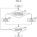
- FIG. 9 is a flowchart illustrating an example of the above control.
- the controller 9 selects the first voltage (step S303) in the case of not the intermediate portion of the paper sheet to be adsorbed (No in step S301), and selects the second voltage that is lower than the first voltage (step S302) in the case of the intermediate portion of the paper sheet to be adsorbed (Yes in step S301).
- the above-described process is repeated until the recording is terminated (step S304).
- this control can be applied to the voltage application charging in step S103 in the control illustrated in FIG. 5 .
- the control illustrated in FIG. 8 can be further applied.
- the controller 9 switches between the frictional charging and the voltage application charging of a surface of the recording paper sheet, which is in contact with the adsorption surface 18d, along the transport direction Y, according to a recording position of the recording paper sheet in the transport direction Y.
- the ink is ejected to an area Wp in the first surface Sa that is one surface of the recording paper sheet P1.
- the recording paper sheet P1 is reversed, and the area Wp comes into contact with the adsorption surface 18d as illustrated in FIG. 7 , the first voltage is selected in the area of the adsorption surface 18d, which is in contact with the area Wp, and the second voltage is selected in an area where the other area except for the area Wp is in contact with the first surface Sa.
- both the suppression of an amount of generated ozone and the proper adsorption of the recording paper sheet to the adsorption surface 18d can be performed.
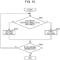
- FIG. 10 is a flowchart illustrating an example of the above control.
- the controller 9 selects the first voltage (step S403) in the case of an already recorded area to be adsorbed (Yes in step S401), and selects the second voltage that is less than the first voltage (step S402) in the case of an unrecorded area to be adsorbed (No in step S401).
- the above-described process is repeated until the recording is terminated (step S404).
- this control can be applied to the voltage application charging in step S103 in the control illustrated in FIG. 5 .
- the control illustrated in FIG. 8 can be further applied.
- the charge removing brush 43 and the charging roller 44 may be disposed upstream of a contact start position f of the recording paper sheet in a rotation direction of the transport belt 18c.
- a distance c between a position e where the charging roller 44 close to the contact start position f is in contact with the transport belt 18c to the contact start position f may be longer than a distance d from a detection position of the sensor 36 in the paper sheet transport path to the contact start position f.
Landscapes
- Feeding Of Articles By Means Other Than Belts Or Rollers (AREA)
- Ink Jet (AREA)
- Accessory Devices And Overall Control Thereof (AREA)
- Handling Of Sheets (AREA)
Abstract
Description
- The present application is based on, and claims priority from
JP Application Serial Number 2018-124635, filed June, 29, 2018 - The present disclosure relates to a recording apparatus that performs recording on a medium.
- In a recording apparatus represented by a printer, a configuration may be adopted in which a medium represented by a recording paper sheet is transported using a transport belt. Further, in this configuration, the medium may be adsorbed to the transport belt by charging the transport belt (see
JP-A-2006-27771 - Ozone may be generated while the transport belt is charged, and a filter may be provided to prevent leakage of the ozone to the outside of the apparatus, depending on the amount of generated ozone. However, in the related art, defect caused by the ozone inside the apparatus is not particularly considered, and for example, there is a possibility that a water-repellent film on a surface of the recording head is contaminated by the ozone, and ink ejection failure occurs. Further, since the transport belt is charged, there is a possibility that the ink is drawn from a nozzle of the recording head disposed to face the charged transport belt, the drawn ink is thickened, and thus ink ejection failure occurs.
- According to an aspect of the present disclosure, a recording apparatus includes a recording head that performs recording on a medium, a transport belt that has an adsorption surface that adsorbs the medium, and transports the medium to a position facing the recording head, a first charging unit that is in contact with the transport belt to frictionally charge the adsorption surface, a second charging unit that applies a voltage to the transport belt to charge the adsorption surface, and a control unit that controls the first charging unit and the second charging unit, in which the control unit switches between the charging of the adsorption surface by the first charging unit and the charging of the adsorption surface by the second charging unit, according to a state of a surface of the medium, which is in contact with the adsorption surface.
- Embodiments of the present invention will now be described by way of further example only and with reference to the accompanying drawings, in which:
-
FIG. 1 is a perspective view illustrating an outer appearance of an ink jet printer according to the present disclosure. -
FIG. 2 is a side sectional view illustrating the entirety of a paper sheet transport path of the ink jet printer according to the present disclosure. -
FIG. 3 is a side sectional view illustrating a partial area of the paper sheet transport path of the ink jet printer according to the present disclosure. -
FIG. 4 is a side sectional view illustrating a partial area of the paper sheet transport path of the ink jet printer according to the present disclosure. -
FIG. 5 is a flowchart illustrating an example of recording control of the inkjet printer according to the present disclosure. -
FIG. 6 is a diagram schematically illustrating an area of a recording sheet. -
FIG. 7 is a diagram schematically illustrating an area of a recording sheet. -
FIG. 8 is a flowchart illustrating an example of recording control of the inkjet printer according to the present disclosure. -
FIG. 9 is a flowchart illustrating an example of recording control of the ink jet printer according to the present disclosure. -
FIG. 10 is a flowchart illustrating an example of recording control of the ink jet printer according to the present disclosure. - Hereinafter, the present disclosure will be described schematically.
- A recording apparatus according to a first aspect of the present disclosure includes a recording head that performs recording on a medium, a transport belt that has an adsorption surface that adsorbs the medium, and transports the medium to a position facing the recording head, a first charging unit that is in contact with the transport belt to frictionally charge the adsorption surface, a second charging unit that applies a voltage to the transport belt to charge the adsorption surface, and a control unit that switches between charging of the adsorption surface by the first charging unit and charging of the adsorption surface by the second charging unit, in which the control unit switches between the charging of the adsorption surface by the first charging unit and the charging of the adsorption surface by the second charging unit, according to a state of a surface of the medium, which is in contact with the adsorption surface.
- According to the present aspect, the recording apparatus includes the first charging unit that is in contact with the transport belt to frictionally charge the adsorption surface that adsorbs the medium, and the second charging unit that applies a voltage to the transport belt to charge the adsorption surface. Since the control unit switches between the charging of the adsorption surface by the first charging unit and the charging of the adsorption surface by the second charging unit according to the state of the surface of the medium, which is in contact with the adsorption surface, the charging of the adsorption surface by the second charging unit is minimized, so that both suppression of the amount of generated ozone and proper adsorption of the medium to the adsorption surface are achieved. Further, as the first charging unit is selected, power consumption can be suppressed. Further, since the control unit switches between the charging of the adsorption surface by the first charging unit and the charging of the adsorption surface by the second charging unit according to the state of the surface of the medium, which is in contact with the adsorption surface, according to the transport belt, a period during which the charging is performed by the second charging unit that performs stronger charging can be reduced, and an increase in viscosity of the ink caused by pulling out an ink from a nozzle of the recording head can be suppressed.
- According to a second aspect of the present disclosure, in the first aspect, the control unit determines whether or not recording is performed on a surface adsorbed to the adsorption surface as a state of the surface of the medium, selects the charging of the adsorption surface by the first charging unit when the surface of the medium on which the recording is not performed is adsorbed to the adsorption surface, and selects the charging of the adsorption surface by the second charging unit when the surface of the medium on which the recording is already performed is adsorbed to the adsorption surface.
- In particular, when recording is performed by ejecting a liquid to the medium, on a surface of the medium to which the liquid is ejected, that is, the surface of the medium on which the recording is already performed, and a surface of the medium to which the liquid is not ejected, that is, the surface of the medium on which the recording is not performed, the latter, that is, the surface of the medium on which the recording is not performed, has low electric conductivity, and is adsorbed to the adsorption surface well. According to the present aspect, since the control unit selects the charging of the adsorption surface by the first charging unit when the surface of the medium on which the recording is not performed is adsorbed to the adsorption surface, and selects the charging of the adsorption surface by the second charging unit when the surface of the medium on which the recording is already performed is adsorbed to the adsorption surface, both when the surface of the medium on which the recording is already performed is adsorbed and when the surface of the medium on which the recording is not performed is adsorbed, the medium can be properly adsorbed.
- According to a third aspect, in the first to second aspects, the charging of the adsorption surface by the second charging unit is configured to be switched between charging by application of a first voltage and charging by application of a second voltage that is less than the first voltage, and when the charging of the adsorption surface by the second charging unit is selected, the control unit selects the first voltage in a contact area of the adsorption surface, which is in contact with the medium, and selects the second voltage in a non-contact area of the adsorption surface, which is not in contact with the medium.
- According to the present aspect, when the second charging unit is selected, since the control unit selects the first voltage in the contact area of the adsorption surface, which is in contact with the medium, and selects the second voltage that is lower than the first voltage in the non-contact area of the adsorption surface, which is not in contact with the medium, the amount of generated ozone when the second charging unit is selected can be suppressed.
- Further, in the present specification, the second voltage includes 0 V.
- According to a fourth aspect of the present disclosure, in the first to second aspects, the charging of the adsorption surface by the second charging unit is configured to be switched between charging by application of a first voltage and charging by application of a second voltage that is less than the first voltage, and when the charging of the adsorption surface by the second charging unit is selected, the control unit selects the first voltage in an area of the adsorption surface which is in contact with a leading end and a trailing end of the medium and selects the second voltage in an area of the adsorption surface, which is in contact with an intermediate portion between the leading end and the trailing end of the medium.
- According to the present aspect, when the second charging unit is selected, the control unit selects the first voltage in the area of the adsorption surface that is in contact with the leading end and the trailing end of the medium, and selects the second voltage that is lower than the first voltage in the area of the adsorption surface, which is in contact with the intermediate portion between the leading end and the trailing end of the medium, floating from the adsorption surface can be satisfactorily suppressed by selecting the first voltage in the leading end and the trailing end of the medium, and the amount of the generated ozone can be suppressed by selecting the second voltage in the area which is in contact with the intermediate portion between the leading end and the trailing end of the medium.
- Further, in the present specification, the second voltage includes 0 V.
- According to a fifth aspect of the present disclosure, in the first aspect, the control unit determines a recording density of a surface adsorbed to the adsorption surface as a state of the surface of the medium, and switches between the first charging unit and the second charging unit according to the recording density of the surface of the medium, which is in contact with the adsorption surface.
- According to a sixth aspect, in the first aspect, the control unit selects the charging of the adsorption surface by the first charging unit when the recording density of the surface of the medium, which is in contact with the adsorption surface, is low, and selects the charging of the adsorption surface by the second charging unit when the recording density of the surface of the medium, which is in contact with the adsorption surface, is high.
- According to the present aspect, since the control unit switches between the first charging unit and the second charging unit according to the recording density of the surface of the medium, which is in contact with the adsorption surface, both suppression of the amount of generated ozone and proper adsorption of the medium to the adsorption surface can be achieved.
- According to a seventh aspect of the present disclosure, in the first aspect, the control unit determines a recording position of the medium in a transport direction on a surface adsorbed to the adsorption surface as a state of the surface of the medium, and switches between the first charging unit and the second charging unit along the transport direction according to a recording position of the medium in the transport direction on the surface of the medium, which is in contact with the adsorption surface.
- According to an eighth aspect, in the first aspect, the control unit selects the charging of the adsorption surface by the first charging unit in an intermediate area of the medium in the transport direction on the surface of the medium, which is in contact with the adsorption surface, and selects the charging of the adsorption surface by the second charging unit in an end portion area of the medium in the transport direction on the surface of the medium, which is in contact with the adsorption surface.
- According to the present aspect, since the control unit switches between the first charging unit and the second charging unit along the transport direction according to a recording position of the medium in the transport direction on the surface of the medium, which is in contact with the adsorption surface, both suppression of the amount of generated ozone and proper adsorption of the medium to the adsorption surface can be achieved.
- According to a ninth aspect, in any one of the first to sixth aspects, the first charging unit and the second charging unit charge the adsorption surface to have a positive polarity.
- According to the present aspect, in a configuration in which the adsorption surface is charged to have a positive polarity, the operational effects of any one of the first to sixth aspects described above can be obtained.
- According to a tenth aspect, in the first to seventh aspects, the recording apparatus further includes a charge removing brush that is configured to come into contact with the adsorption surface, and a switching unit that switches whether or not the charge removing brush is grounded, in which the first charging unit is configured with the not-grounded charge removing brush.
- According to the present aspect, since the charge removing brush, which is a configuration for removing charges, also serves as the first charging unit, an increase in costs can be suppressed by reducing the number of components.
- Hereinafter, the present disclosure will be described in detail.
- Hereinafter, an ink jet printer (hereinafter, referred to as a "printer") that performs ink jet recording on a recording paper sheet that is an example of a medium is described as an example of a recording apparatus according to the present disclosure. Further, in an ink jet method, the present disclosure may be applied even to any form such as a type in which an ink cartridge is mounted on a carriage and a type in which an ink containing portion is provided outside a carriage and the ink containing portion and the carriage are connected to each other using an ink tube. Further, a
printer 1 according to the present embodiment is of a type in which an ink containing portion is provided outside a carriage and the ink containing portion and the carriage are connected to each other through an ink tube. - Further, a recording head that ejects an ink is of a type in which the recording head moves in a paper sheet width direction and a type in which the recording head is formed to have a size that covers the paper sheet width direction and does not move. The
printer 1 according to the present embodiment corresponds to the latter type. - In an x-y-z coordinate system illustrated in the drawings, an x direction indicates a device depth direction and the paper sheet width direction, a y direction indicates a device width direction, and a z direction indicates a device height direction and a gravity direction. Further, a direction in which the recording paper sheet is transported is referred to as "downstream", and a direction that is opposite thereto is referred to as "upstream".
- Hereinafter, the entire configuration of the
printer 1 will be described with reference toFIGs. 1 and2 . - In
FIG. 1 , theprinter 1 includes ascanner unit 3 on amain device body 2A that performs recording on the recording paper sheet, and includesextension units main device body 2A. Themain device body 2A includes apaper sheet cassette 10A, theextension unit 2B includes apaper sheet cassette 10B, and theextension unit 2C includes apaper sheet cassette 10C. Theseextension units main device body 2A. -
Reference numeral 5 denotes an operation unit that performs various operations of theprinter 1, andreference numeral 4 denotes a tray for receiving the recording paper sheet to be discharged after recording, and more particularly, a face-down paper discharge tray for receiving the recording paper sheet discharged while a recording surface on which the recording is recently performed is directed to the lower side. Further,reference numeral 35 denotes a feeding unit, which can be opened and closed with respect to themain device body 2A as the feeding unit pivots about a not-illustrated pivoting point. -
Reference numeral 6 denotes an opening and closing cover constituting thefeeding unit 35, which can rotate about arotary shaft 6a (seeFIG. 2 ) and can be opened and closed in a direction indicated by arrows e and f. InFIG. 1 , an imaginary line and reference numeral 6-1 denote the opening and closing cover during opening and closing. - A manual feeding tray 41 (see
FIG. 2 ) is provided inside the opening andclosing cover 6. Themanual feeding tray 41 rotates about arotary shaft 41a and can be opened and closed together with the opening andclosing cover 6. Further, themanual feeding tray 41 illustrated inFIG. 2 is in a storage posture, is opened in a clockwise direction from a state ofFIG. 2 , and enables manual paper feeding while being directed to the obliquely upper side. - Further, in the
printer 1, a side on which theoperation unit 5 is disposed is the front side of the apparatus, and a side on which the opening andclosing cover 6 is provided is a right side surface of the apparatus. That is, in theprinter 1, feeding, transporting, and discharging of the recording paper sheet are performed along a left-right direction of the apparatus. - Next, a paper sheet feeding path of the
printer 1 will be described with reference toFIG. 2 . Theprinter 1 has three feeding paths including a feeding path from thepaper sheet cassette 10A (see a cassette feeding trajectory S1), a feeding path from thepaper sheet cassettes FIG. 2 (see an extension cassette feeding trajectory S2), and a feeding path from themanual feeding tray 41 on which the recording paper sheet is mounted (see a manual feeding path S3). - Further, the
printer 1 has two paper sheet discharge methods including face-up discharge in which the recording surface on which the recording is recently performed is discharged while being directed to the upper side (see a face-up discharge trajectory T1) and face-down discharge in which the recording surface on which the recording is recently performed is discharged while being directed to the lower side (see a face-down discharge trajectory T2). - Further, in
FIG. 2 , reference numeral 7 denotes a face-up discharge tray for receiving a face-up-discharged recording paper sheet. As the face-up discharge tray 7 rotates about arotary shaft 7a, a storage state illustrated inFIG. 2 and a not-illustrated open state are taken. - Thus, the
printer 1 includes five paper sheet transport paths including a recording transport path R1, a switchback path R2, a reverse path R3, a face-down discharge path R4, and a face-up discharge path R5. - In
FIG. 2 ,reference numeral 33 denotes a flap (a path switching member) driven by a not-illustrated driving source, which is switched between a state indicated by a solid line ofFIG. 2 andreference numeral 33 and a state indicated by the imaginary line and reference numeral 33-1. - When the
flap 33 is in the state indicated by a solid line ofFIG. 2 , the recording paper sheet is guided to the face-down discharge path R4, and is then face-down-discharged as indicated by the face-down discharge trajectory T2. - When the
flap 33 is in the state of the imaginary line and reference numeral 33-1 ofFIG. 2 , the recording paper sheet is guided to the face-up discharge path R5, and is then face-up-discharged as indicated by the face-up discharge trajectory T1. - Hereinafter, a paper sheet feeding path up to a resist
roller pair 17 will be described with reference toFIG. 2 . - The
paper sheet cassette 10A detachably provided in themain device body 2A includes ahopper 11. As thehopper 11 swings about ashaft 11a, the recording paper sheet accommodated in thepaper sheet cassette 10A is brought into contact with and separated from a feedingroller 12 rotationally driven by a not-illustrated motor. - The recording paper sheet sent from the
paper sheet cassette 10A by the feedingroller 12 is separated (is prevented from being double-fed) by passing through a nipping position by aseparation roller pair 13, and receives a sending force from thetransport roller pair 14 to reach the resistroller pair 17. Similarly, theextension units FIG. 1 ) located below themain device body 2A also include the feedingrollers 12 and the separation roller pairs 13, and the recording paper sheet sent from each paper sheet cassette receives the sending force from thetransport roller pair 14 illustrated inFIG. 2 to reach the resistroller pair 17. - Further, a feeding
roller 15 and aseparation roller 16 are provided in a paper sheet feeding path (the manual feeding path S3) from themanual feeding tray 41, and the recording paper sheet set on themanual feeding tray 41 reaches the resistroller pair 17 by rotation of these rollers. - Hereinafter, a paper sheet transport path downstream of the resist
roller pair 17 will be described with reference toFIG. 3 . Further, inFIG. 3 , it is assumed that the recording paper sheet is face-down-discharged through the face-down discharge path R4. - First, a roller provided in each paper sheet transport path will be described. In
FIG. 3 ,reference numeral 17 denotes the resist roller pair,reference numerals 20 to 24 and 26 to 29 denote all transport roller pairs that transport the recording paper sheet, andreference numeral 25 denotes a discharge roller pair that discharges the recording paper sheet. In the roller pairs, symbol F denotes one roller of each roller pair other than the resistroller pair 17 andtransport roller pair 29, and symbol G denotes the other roller. Further, thedischarge roller pair 25 provided on the most downstream side of the face-down discharge path R4 constitutes a discharge unit for discharging the recording paper sheet from the face-down discharge path R4. - The rollers F are driving rollers driven by not-illustrated motors. For example, the rollers F are rubber rollers provided at appropriate intervals in the paper sheet width direction.
- The rollers G, which are driven rollers that can nip the recording paper sheet between the rollers F by not-illustrated biasing means and perform driven rotation while coming into contact with the recording paper sheet, are provided in pair with the rollers F at appropriate intervals in the paper sheet width direction. The rollers G, which are incision rollers having a plurality of teeth on an outer circumference thereof, comes into point contact with the recording surface to suppress white spots or transfer of an ink on the already recorded surface.
- Further, the driven rollers G are provided at appropriate positions on the paper sheet transport path in addition to constituting each transport roller pair, and are particularly provided on a side in contact with the nearest recording surface.
- Meanwhile, configurations of the resist
roller pair 17 and thetransport roller pair 29 are different from the configurations of the above-described roller pairs. In detail, thetransport roller pair 29 includes a drivingroller 29a that performs rotation driving and a drivenroller 29b pressed toward the drivingroller 29a and capable of driven rotation. Among them, the drivenroller 29b is a resin roller having a smooth outer circumferential surface. - The resist
roller pair 17 includes a drivingroller 17a that performs rotation driving and a drivenroller 17b pressed toward the drivingroller 17a by not-illustrated biasing means and capable of driven rotation. Among them, the drivingroller 17a is a roller having fine unevennesses on an outer circumference thereof, and the drivenroller 17b is a resin roller having a smooth outer circumferential surface. - A plurality of the driving
rollers 17a are provided at appropriate intervals along an axial direction with respect to arotary shaft 17c (FIG. 4 ). Similarly, a plurality of the drivenrollers 17b are provided at appropriate intervals along an axial direction with respect to arotary shaft 17d (FIG. 4 ). - The recording paper sheet is guided between the above-described rollers by the following guide member. In
FIG. 2 to 4 , in order to avoid complication of the drawing, no sign is attached to the guide member. However, a thick line connecting the rollers indicates the above-described guide member. Further, InFIG. 4 and subsequent figures, illustration of the guide member is omitted as appropriate. - Next, the recording transport path R1 as a first transport path passes through a lower side of a
recording head 8 as a recording unit that performs the recording on the recording paper sheet, and extends to an upstream side and a downstream side thereof. In the present embodiment, for convenience, the recording transport path R1 approximately extends from a position M1 to a position M2 ofFIG. 3 . In the recording transport path R1, the paper sheet receives the sending force from the resistroller pair 17 and abelt unit 18. - In the present embodiment, the
recording head 8 as recording means, which is a recording head (a so-called line head) provided as if a nozzle that ejects an ink covers the entire area in the paper sheet width direction, is configured as a recording head that can perform the recording on the entire paper sheet width without movement in the paper sheet width direction. - The switchback path R2 as a second transport path, which is a transport path connected to the recording transport path R1 and is a path that sends the recording paper sheet passing through the lower side of the recording head 8 (a left side of
FIG. 3 ), switches back the recording paper sheet, and transports the recording paper sheet in an opposite direction to the sending direction (a right side ofFIG. 3 ), is located inside a curvature with respect to the face-down discharge path R4, which will be described below. In the present embodiment, for convenience, the switchback path R2 is located approximately on the left side of a position M3 ofFIG. 3 . In the switchback path R2, the recording paper sheet receives the sending force from thetransport roller pair 26. - The reverse path R3 as a third transport path, which is a transport path connected to the switchback path R2, reverses the recording paper sheet transported in the opposite direction (a right side of
FIG. 3 ) by bypassing the upper side of therecording head 8, and is joined to an upstream position of therecording head 8 in the recording transport path R1 (in the present embodiment, an upstream position of the resist roller pair 17). In the present embodiment, for convenience, the reverse path R3 is set as a path approximately extending from a position M3 to a position M4 ofFIG. 3 . In the reverse path R3, the recording paper sheet receives the sending force from the transport roller pairs 27, 28, and 29. - The face-down discharge path R4 as a fourth transport path, which is a transport path connected to the recording transport path R1, is a path that reverses and discharges the recording paper sheet passing through a lower side of the
recording head 8 by curving a surface facing therecording head 8. In the present embodiment, for convenience, the face-down discharge path R4 is located approximately on the left side of a position M2 ofFIG. 3 . In the face-down discharge path R4, the recording paper sheet receives the sending force from the transport roller pairs 20, 21, 22, 23, 24 and thedischarge roller pair 25. - Further, a
first flap 31 and asecond flap 32 as a path switching member that switches the transport paths are provided at a connection portion between the transport paths. As thefirst flap 31 receives a driving force from not-illustrated driving means, thefirst flap 31 can swing about aswinging supporting point 31a. Further, thesecond flap 32 is provided to be engaged with thefirst flap 31 through a not-illustrated engagement portion, and swings about aswinging supporting point 32a according to swinging of thefirst flap 31. - With these flaps, a path along which the recording paper sheet is advanced is set.
- Next, the
belt unit 18 and a peripheral configuration thereof will be described with reference toFIG. 4 . Atransport belt 18c constituting thebelt unit 18, which is an endless belt made of a base material made of urethane, rubber, or the like and containing a conductive material to adjust a resistance value as needed, is hung on and rotated by theupstream driving pulley 18a and the downstream drivenpulley 18b, and a predetermined tension is applied to thetransport belt 18c by a not-illustrated tensioner. - The driving
pulley 18a is controlled by acontroller 9 to perform rotation driving by amotor 37. When the drivingpulley 18a performs rotation driving, thetransport belt 18c operates, and the recording paper sheet adsorbed to thetransport belt 18c is transported. -
Support plates transport belt 18c, and inward deflection of thetransport belt 18c is regulated by thesupport plates support plates - A charging
roller 44 is provided at a position facing the drivingpulley 18a with thetransport belt 18c interposed therebetween. In the present embodiment, theprinter 1 includes a first charging unit and a second charging unit as a unit for charging thetransport belt 18c, and the chargingroller 44 constitutes the second charging unit. - The charging
roller 44 is in contact with an outer surface of thetransport belt 18c to perform driven rotation according to an operation of thetransport belt 18c. Apower source unit 49 that applies a direct current (DC) voltage to the chargingroller 44 is connected to the chargingroller 44. Accordingly, the chargingroller 44 supplies an electric charge from a portion in contact with thetransport belt 18c. Thepower source unit 49 is controlled by thecontroller 9 to switch on and off application of a voltage to the chargingroller 44 and to switch a voltage applied to the chargingroller 44. Further, in the present embodiment, the chargingroller 44 supplies a positive electric charge to thetransport belt 18c, and charges an outer surface of thetransport belt 18c to have a positive polarity. That is, the outer surface of thetransport belt 18c is set as anadsorption surface 18d for suctioning the recording paper sheet. - The driven
roller 19a is provided above the drivingpulley 18a with thetransport belt 18c interposed therebetween. Similarly, the drivenroller 19b is provided above the drivenroller 18b with thetransport belt 18c interposed therebetween. The recording paper sheet transported by thetransport belt 18c is pressed against thetransport belt 18c by the drivenrollers - Further, the driven
rollers - A
charge removing brush 43 that comes into contact with the recording paper sheet is provided upstream of therecording head 8, and electric charges on an upper surface of the recording paper sheet and an outer surface of thetransport belt 18c, that is, anadsorption surface 18d, are removed by thecharge removing brush 43. - In more detail, when electric charges are applied to the
adsorption surface 18d of thetransport belt 18c by the chargingroller 44, charges having polarity opposite to polarity of a surface in contact with theadsorption surface 18d are generated on the recording paper sheet in contact with theadsorption surface 18d. Further, charges having polarity opposite to the charges are generated on an opposite surface of the recording paper sheet, that is, the recording surface. Charges on the recording surface are removed by thecharge removing brush 43. Accordingly, only charges on a side in contact with thetransport belt 18c remain on the recording paper sheet. As a result, the recording paper sheet is adsorbed to theadsorption surface 18d. - The
charge removing brush 43 may be made of any material as long as the material can remove charges from the recording paper sheet and thetransport belt 18c and may be made of a resin material such as a conductive nylon. - Further, the
charge removing brush 43 is used to remove charges of thetransport belt 18c. Thecharge removing brush 43 is connected to aswitching unit 48 as a switching unit, and thecharge removing brush 43 switches between a state in which thecharge removing brush 43 is grounded and a state in which thecharge removing brush 43 is not grounded, under a control of thecontroller 9. - A
cleaning blade 47 is provided below thebelt unit 18. Thecleaning blade 47 is provided with thetransport belt 18c sandwiched between thesupport plate 46 and thecleaning blade 47. Ink and foreign matters adhering to theadsorption surface 18d are removed by wiping theadsorption surface 18d of thetransport belt 18c. Thecleaning blade 47 can be formed of a resin material such as a polyethylene terephthalate (PET) film or the like. Further, thecleaning blade 47 can be also provided to be switched between a state in which thecleaning blade 47 is connected to thetransport belt 18c and a state in which thecleaning blade 47 is separated from thetransport belt 18c. - Further, similarly to the above-described
charge removing brush 43, as thecleaning blade 47 is connected to a switching unit for switching between a state in which thecleaning blade 47 is grounded and a state in which thecleaning blade 47 is not grounded, thecleaning blade 47 may be used as the first charging unit, which will be described below, in addition to thecharge removing brush 43 or instead of thecharge removing brush 43. - The above-described
motor 37, thepower supply unit 49, and the switchingunit 48 are connected to thecontroller 9 as a control unit. Thecontroller 9 acquires recording data that is data for performing recording, generated by a printer driver operated by a not-illustrated external computer or a printer driver included in thecontroller 9, and controls respective mechanisms including therecording head 8 or motors for transporting the recording paper sheet, based on the recording data. Further, thecontroller 9 performs necessary control based on the detection state of various sensors. - A
sensor 36 illustrated inFIG. 4 is provided between the resistroller pair 17 and thebelt unit 18 and sends a detection signal to thecontroller 9. Accordingly, thecontroller 9 can detect passage of a leading end and a trailing end of the recording paper sheet in a position of thesensor 36. - For example, the
controller 9 can determine a timing when theadsorption surface 18d starts to be charged by the chargingroller 44 upon the detection of the passage of the leading end of the recording paper sheet in the position of thesensor 36, and can determine a timing when charging of theadsorption surface 18d is terminated by the chargingroller 44 upon the detection of the passage of the trailing end of the recording paper sheet. - Further, in the present embodiment, the resist
roller pair 17 or the drivingpulley 18a uses themotor 37 as a common driving source. A paper sheet transport speed by the resistroller pair 17 and a paper sheet transport speed by thebelt unit 18 are determined based on a speed reduction ratio of a gear group that transmits power from themotor 37 to the resistroller pair 17 and the drivingpulley 18a. - However, the resist
roller pair 17 and the drivingpulley 18a may be driven using separate motors, respectively. - Next, switching of the charging units will be described with reference to
FIG. 4 to 6 . The above-describedprinter 1 includes the first charging unit and the second charging unit as a unit for charging theadsorption surface 18d of thetransport belt 18c. The first charging unit is a unit for frictionally charging theadsorption surface 18d, and the second charging unit is a unit for charging theadsorption surface 18d by applying a voltage to thetransport belt 18c. Thus, thecontroller 9 switches between charging of theadsorption surface 18d by the first charging unit and charging of theadsorption surface 18d by the second charging unit, according to a state of a surface of the recording paper sheet in contact with thetransport belt 18c. Hereinafter, the charging of theadsorption surface 18d by the first charging unit may be called frictional charging, and the charging of theadsorption surface 18d by the second charging unit may be called voltage application charging. - In the present embodiment, the second charging unit is configured with the charging
roller 44 as described above, and charges theadsorption surface 18d to have a positive polarity by the chargingroller 44. In the present embodiment, the first charging unit is configured with thecharge removing brush 43, and charges theadsorption surface 18d to have a positive polarity by thecharge removing brush 43. - The switching
unit 48 connected to thecharge removing brush 43 can be switched between a state in which thecharge removing brush 43 is grounded and a state in which thecharge removing brush 43 is not grounded, under the control of thecontroller 9. In the state in which thecharge removing brush 43 is not grounded, as thecharge removing brush 43 comes into contact with thetransport belt 18c in operation, theadsorption surface 18d is frictionally charged. In order to positively charge theadsorption surface 18d, thecharge removing brush 43 may be made of a material on a minus side compared to a material forming thetransport belt 18c on charge series representing ease of the charging (in other words, the material of thecharge removing brush 43 is less easily charged than the material of thetransport belt 18c). - As described above, since the
charge removing brush 43, which is a configuration for removing charges, also serves as the first charging unit, an increase in costs can be suppressed by reducing the number of components. - Further, even in a state in which the
switching unit 48 is in contact with thecharge removing brush 43, when charges of theadsorption surface 18d are not completely removed by thecharge removing brush 43, and a certain amount of charges remains on theadsorption surface 18d, the frictional charging may be performed in a state in which theswitching unit 48 grounds thecharge removing brush 43. Thus, a configuration can be also adopted in which theswitching unit 48 is omitted. - Thus, as the frictional charging is selected, the
controller 9 can adsorb the recording paper sheet to theadsorption surface 18d while preventing occurrence of ozone due to a charging process by the voltage application charging. In other words, as use of the voltage application charging is suppressed to minimum, both suppression of an amount of generated ozone and proper adsorption of the recording paper sheet to theadsorption surface 18d can be performed. - Further, as the frictional charging is selected, power consumption of the
printer 1 can be suppressed. - Thus, when the frictional charging is used, the voltage application charging is not used. In contrast, when the voltage application charging is used, the frictional charging is not used. However, when the voltage application charging is used, the frictional charging may be used together with it.
- Hereinafter, description will be made in more detail with reference to
FIG. 5 . Before the leading end of the recording paper sheet reaches thetransport belt 18c, thecontroller 9 determines whether or not a surface of the recording paper sheet, which is in contact with theadsorption surface 18d, is a surface to which the ink is already ejected, that is, an already recorded surface (step S101), and when it is determined that the surface is an unrecorded surface to which the ink is not ejected (No in step S101), uses frictional charging (step S104). - Here, as illustrated in
FIG. 6 , an unrecorded surface is a second surface Sb of the recording paper sheet, that is, a surface opposite to a first surface Sa that is a surface firstly facing therecording head 8 or is the first surface Sa when the recording is not performed on the first surface Sa and the recording paper sheet is reversed. - Referring back to
FIG. 5 , in step S101, in contrast, when a surface of the recording paper sheet, which is in contact with theadsorption surface 18d, is an already recorded surface (Yes in step S101), whether or not a recording density is equal to or more than a predetermined threshold is determined (step S102), and when the recording density is less than the predetermined threshold (No in step S102), the frictional charging is used (step S104). - In contrast, when a recording density is equal to or more than a predetermined threshold (Yes in step S102), the voltage application charging is used (step S103).
- Thus, when there is a next recording operation (Yes in step S105), the process returns to step S101.
- That is, in the already recorded surface to which the ink is ejected and the unrecorded surface to which the ink is not ejected, the latter has a lower electrical conductivity than electrical conductivity of the former, and thus is adsorbed to the
adsorption surface 18d well. Further, when the recording density is low, the already recorded surface is adsorbed to theadsorption surface 18d well. Here, the recording density means an area of ink ejected per unit area. - In this way, the
controller 9 selects the frictional charging when the unrecorded surface is adsorbed to theadsorption surface 18d and selects the voltage application charging when the already recorded surface is adsorbed to theadsorption surface 18d. Accordingly, both when the already recorded surface is adsorbed and when the unrecorded surface is adsorbed, the recording paper sheet can be adsorbed appropriately. Further, even in the already recorded surface, since the frictional charging and the voltage application charging are switched according to the recording density, both the suppression of the amount of generated ozone and the proper adsorption of the recording paper sheet to theadsorption surface 18d can be achieved by the voltage application charging. - Further, a process based on the determination in step S102, that is, a process of switching between the frictional charging and the voltage application charging according to the recording density, can be omitted. Regardless of the recording density, in the case of the already recorded surface, the voltage application charging may be selected always.
- The above-described control example can be further described as follows.
- (1) The charging of the
adsorption surface 18d by the voltage application charging is switched between charging by application of a first voltage and charging by application of a second voltage that is less than the first voltage. When thecontroller 9 selects the voltage application charging, in a contact area of theadsorption surface 18d, which is in contact with the recording paper sheet, the first voltage may be selected, and in a non-contact area of theadsorption surface 18d, which is not in contact with the recording paper sheet, the second voltage may be selected. Accordingly, the amount of generated ozone when the voltage application charging is selected can be suppressed. - The non-contact area of the
adsorption surface 18d, which is not in contact with the recording paper sheet, is an area between the preceding recording paper sheet and the following recording paper sheet as an example. - In
FIG. 6 , reference numeral P1 denotes the preceding paper sheet, and reference numeral P2 denotes the following paper sheet. The range of theadsorption surface 18d, which corresponds to an area Wk between a trailing end R of the preceding paper sheet P1 and a leading end F of the following paper sheet P2, is an example of the non-contact area of theadsorption surface 18d, which is not in contact with the recording paper sheet. - Further, the non-contact area of the
adsorption surface 18d, which is not in contact with the recording paper sheet, may be theentire adsorption surface 18d before start of a recording job or theentire adsorption surface 18d after termination of the recording job. - Further, the second voltage includes 0 V.
-
FIG. 8 is a flowchart illustrating an example of the above control. Thecontroller 9 selects the first voltage (step S203) when theadsorption surface 18d is in contact with the recording paper sheet (Yes in step S201), and selects the second voltage that is lower than the first voltage (step S202) when theadsorption surface 18d is not in contact with the recording paper sheet (No in step S201). The above-described process is repeated until the recording is terminated (step S204). - Further, this control can be applied to the voltage application charging in step S103 in the control illustrated in
FIG. 5 . - (2) When the voltage application charging is selected, the
controller 9 may select the first voltage in the area of theadsorption surface 18d illustrated inFIG. 6 where a leading end Wf and a trailing end Wr of the recording paper sheet are in contact with each other, and the second voltage may be selected in an intermediate portion Wc between the leading end Wf and the trailing end Wr of the recording paper sheet. - Accordingly, floating from the
adsorption surface 18d can be satisfactorily suppressed by selecting the first voltage at the leading end Wf and the trailing end Wr of the recording paper sheet. Thus, occurrence of ozone can be suppressed by selecting the second voltage in the intermediate portion Wc between the leading end Wf and the trailing end Wr. - Further, even in the present embodiment, the second voltage includes 0 V.
-
FIG. 9 is a flowchart illustrating an example of the above control. Thecontroller 9 selects the first voltage (step S303) in the case of not the intermediate portion of the paper sheet to be adsorbed (No in step S301), and selects the second voltage that is lower than the first voltage (step S302) in the case of the intermediate portion of the paper sheet to be adsorbed (Yes in step S301). The above-described process is repeated until the recording is terminated (step S304). - Further, this control can be applied to the voltage application charging in step S103 in the control illustrated in
FIG. 5 . At this time, the control illustrated inFIG. 8 can be further applied. - (3) The
controller 9 switches between the frictional charging and the voltage application charging of a surface of the recording paper sheet, which is in contact with theadsorption surface 18d, along the transport direction Y, according to a recording position of the recording paper sheet in the transport direction Y. - For example, in
FIG. 6 , it is assumed that the ink is ejected to an area Wp in the first surface Sa that is one surface of the recording paper sheet P1. Further, when the recording paper sheet P1 is reversed, and the area Wp comes into contact with theadsorption surface 18d as illustrated inFIG. 7 , the first voltage is selected in the area of theadsorption surface 18d, which is in contact with the area Wp, and the second voltage is selected in an area where the other area except for the area Wp is in contact with the first surface Sa. - Accordingly, both the suppression of an amount of generated ozone and the proper adsorption of the recording paper sheet to the
adsorption surface 18d can be performed. -
FIG. 10 is a flowchart illustrating an example of the above control. Thecontroller 9 selects the first voltage (step S403) in the case of an already recorded area to be adsorbed (Yes in step S401), and selects the second voltage that is less than the first voltage (step S402) in the case of an unrecorded area to be adsorbed (No in step S401). The above-described process is repeated until the recording is terminated (step S404). - Further, this control can be applied to the voltage application charging in step S103 in the control illustrated in
FIG. 5 . At this time, the control illustrated inFIG. 8 can be further applied. - Further, in
FIG. 4 , thecharge removing brush 43 and the chargingroller 44 may be disposed upstream of a contact start position f of the recording paper sheet in a rotation direction of thetransport belt 18c. Among them, particularly, a distance c between a position e where the chargingroller 44 close to the contact start position f is in contact with thetransport belt 18c to the contact start position f may be longer than a distance d from a detection position of thesensor 36 in the paper sheet transport path to the contact start position f. - That is, when the distance c is shorter than the distance d, at a time point when a leading end of a paper sheet reaches the contact start position f, there is a possibility that the
adsorption surface 18d of thetransport belt 18c is not charged. However, in the present embodiment, since the distance c is longer than the distance d, at a time point when the leading end of the paper sheet reaches the contact start position f, theadsorption surface 18d is certainly charged. - In particular, this is suitable when the paper sheet transport speed by the resist
roller pair 17 is equal to the paper sheet transport speed by thetransport belt 18c. - The present disclosure is not limited to the above-described embodiments. However, it is apparent that various modifications can be made without departing from the scope of the present disclosure described in the appended claims, and are included in the scope of the present disclosure.
Claims (10)
- A recording apparatus (1) comprising:a recording head (8) configured to perform recording on a medium (P);a transport belt (18c) that has an adsorption surface (18d) configured to adsorb the medium, and transport the medium to a position facing the recording head;a first charging unit (43) that is in contact with the transport belt to frictionally charge the adsorption surface;a second charging unit (44) configured to apply a voltage to the transport belt to charge the adsorption surface; anda control unit (9) configured to switch between charging of the adsorption surface by the first charging unit and charging of the adsorption surface by the second charging unit, whereinthe control unit is configured to switch between the charging of the adsorption surface by the first charging unit and the charging of the adsorption surface by the second charging unit, according to a state of a surface (Sb)of the medium, which is in contact with the adsorption surface.
- The recording apparatus according to claim 1, wherein
the control unit is configured to
determine whether or not recording is performed on a surface adsorbed to the adsorption surface as a state of the surface of the medium,
when the surface of the medium on which the recording is not performed is adsorbed to the adsorption surface, select the charging of the adsorption surface by the first charging unit, and
when the surface of the medium on which the recording is already performed is adsorbed to the adsorption surface, select the charging of the adsorption surface by the second charging unit. - The recording apparatus according to claim 1 or claim 2, wherein
the charging of the adsorption surface by the second charging unit is configured to be switched between charging by application of a first voltage and charging by application of a second voltage that is less than the first voltage, and
when the charging of the adsorption surface by the second charging unit is selected, the control unit is configured select the first voltage in a contact area of the adsorption surface, which is in contact with the medium, and selects the second voltage in a non-contact area of the adsorption surface, which is not in contact with the medium. - The recording apparatus according to any one of the preceding claims, wherein
the charging of the adsorption surface by the second charging unit is configured to be switched between charging by application of a first voltage and charging by application of a second voltage that is less than the first voltage, and
when the charging of the adsorption surface by the second charging unit is selected, the control unit is configured to select the first voltage in an area of the adsorption surface, where a leading end (Wf) and a trailing end (Wr) of the medium are in contact with each other and to select the second voltage in an area of the adsorption surface, which is in contact with an intermediate portion (Wc) between the leading end and the trailing end of the medium. - The recording apparatus according to any one of the preceding claims, wherein
the control unit is configured to determine a recording density of a surface adsorbed to the adsorption surface as a state of the surface of the medium, and switches between the first charging unit and the second charging unit according to the recording density of the surface of the medium, which is in contact with the adsorption surface. - The recording apparatus according to claim 5, wherein
the control unit is configured to select the charging of the adsorption surface by the first charging unit (43) when the recording density of the surface of the medium, which is in contact with the adsorption surface, is low, and select the charging of the adsorption surface by the second charging unit (44) when the recording density of the surface of the medium, which is in contact with the adsorption surface, is high. - The recording apparatus according to any one of the preceding claims, wherein
the control unit is configured to determine a recording position of the medium in a transport direction on a surface adsorbed to the adsorption surface as a state of a surface of the medium, and switch between the first charging unit and the second charging unit along the transport direction according to the recording position of the medium in the transport direction on the surface of the medium, which is in contact with the adsorption surface. - The recording apparatus according to claim 7, wherein
the control unit is configured to select the charging of the adsorption surface by the first charging unit in an intermediate area (Wc) of the medium in the transport direction on the surface of the medium, which is in contact with the adsorption surface, and to select the charging of the adsorption surface by the second charging unit in an end portion area (Wf, Wr) of the medium in the transport direction on the surface of the medium, which is in contact with the adsorption surface. - The recording apparatus according to any one of the preceding claims, wherein
the first charging unit and the second charging unit are configured to charge the adsorption surface to have positive polarity. - The recording apparatus according to any one of the preceding claims, further comprising:a charge removing brush (43) that is configured to come into contact with the adsorption surface; anda switching unit (48) configured to switch whether or not the charge removing brush is grounded, whereinthe first charging unit is configured with the not-grounded charge removing brush.
Applications Claiming Priority (1)
| Application Number | Priority Date | Filing Date | Title |
|---|---|---|---|
| JP2018124635A JP7407503B2 (en) | 2018-06-29 | 2018-06-29 | recording device |
Publications (2)
| Publication Number | Publication Date |
|---|---|
| EP3587129A1 true EP3587129A1 (en) | 2020-01-01 |
| EP3587129B1 EP3587129B1 (en) | 2021-09-08 |
Family
ID=67060322
Family Applications (1)
| Application Number | Title | Priority Date | Filing Date |
|---|---|---|---|
| EP19182171.9A Active EP3587129B1 (en) | 2018-06-29 | 2019-06-25 | Recording apparatus |
Country Status (4)
| Country | Link |
|---|---|
| US (1) | US10882341B2 (en) |
| EP (1) | EP3587129B1 (en) |
| JP (2) | JP7407503B2 (en) |
| CN (1) | CN110654114B (en) |
Families Citing this family (4)
| Publication number | Priority date | Publication date | Assignee | Title |
|---|---|---|---|---|
| JP7407503B2 (en) | 2018-06-29 | 2024-01-04 | セイコーエプソン株式会社 | recording device |
| JP7300722B2 (en) * | 2020-01-09 | 2023-06-30 | 株式会社ユニバーサルエンターテインメント | game machine |
| EP3868563A1 (en) * | 2020-02-18 | 2021-08-25 | Agfa Nv | Inkjet printer for decorating cloth |
| JP7528505B2 (en) * | 2020-04-03 | 2024-08-06 | セイコーエプソン株式会社 | Recording device |
Citations (6)
| Publication number | Priority date | Publication date | Assignee | Title |
|---|---|---|---|---|
| JP2006027771A (en) | 2004-07-13 | 2006-02-02 | Ricoh Co Ltd | Electrostatic transfer device and image forming apparatus |
| US20060050124A1 (en) * | 2003-08-06 | 2006-03-09 | Richoh Company, Ltd. | Image forming apparatus, recording liquid, conveyor belt, recording liquid cartridge |
| US20090052917A1 (en) * | 2005-07-19 | 2009-02-26 | Seiichi Kogure | Image forming apparatus |
| EP2184174A1 (en) * | 2008-11-11 | 2010-05-12 | Brother Kogyo Kabushiki Kaisha | Transport device and recording device |
| EP2341019A2 (en) * | 2009-12-29 | 2011-07-06 | Brother Kogyo Kabushiki Kaisha | Medium feeding apparatus and image recording apparatus |
| JP2018124635A (en) | 2017-01-30 | 2018-08-09 | 株式会社東芝 | Charge processing apparatus and charge processing method |
Family Cites Families (14)
| Publication number | Priority date | Publication date | Assignee | Title |
|---|---|---|---|---|
| JP3224528B2 (en) * | 1990-08-31 | 2001-10-29 | キヤノン株式会社 | Ink jet recording device |
| JP3504469B2 (en) * | 1997-09-09 | 2004-03-08 | シャープ株式会社 | Image forming device |
| JP2007079184A (en) | 2005-09-15 | 2007-03-29 | Ricoh Co Ltd | Electrophotographic equipment |
| JP2007210112A (en) | 2006-02-07 | 2007-08-23 | Fuji Xerox Co Ltd | Liquid droplet discharge apparatus |
| JP2008074578A (en) * | 2006-09-22 | 2008-04-03 | Seiko Epson Corp | Inkjet printer |
| US8322717B1 (en) * | 2011-12-27 | 2012-12-04 | Xerox Corporation | Motion quality by handoff force control between upstream and downstream transports |
| US8840241B2 (en) | 2012-08-20 | 2014-09-23 | Xerox Corporation | System and method for adjusting an electrostatic field in an inkjet printer |
| JP5860783B2 (en) * | 2012-08-31 | 2016-02-16 | 京セラドキュメントソリューションズ株式会社 | Image forming apparatus |
| JP2014205543A (en) * | 2013-04-12 | 2014-10-30 | キヤノン株式会社 | Sheet feeding device and image formation device |
| JP6476604B2 (en) * | 2013-09-12 | 2019-03-06 | 株式会社リコー | Paper transport device, image forming device |
| CN104512744B (en) * | 2013-09-27 | 2017-04-12 | 京瓷办公信息系统株式会社 | Sheet conveying device and image forming apparatus |
| JP2015110832A (en) * | 2013-11-05 | 2015-06-18 | キヤノン・コンポーネンツ株式会社 | Electrostatic adsorption belt, method for manufacturing the same, conveyance system, and printing apparatus |
| US9527316B2 (en) * | 2015-02-25 | 2016-12-27 | Seiko Epson Corporation | Printing apparatus |
| JP7407503B2 (en) | 2018-06-29 | 2024-01-04 | セイコーエプソン株式会社 | recording device |
-
2018
- 2018-06-29 JP JP2018124635A patent/JP7407503B2/en active Active
-
2019
- 2019-06-25 EP EP19182171.9A patent/EP3587129B1/en active Active
- 2019-06-26 US US16/453,144 patent/US10882341B2/en active Active
- 2019-06-27 CN CN201910568938.6A patent/CN110654114B/en active Active
-
2022
- 2022-06-14 JP JP2022095850A patent/JP7687995B2/en active Active
Patent Citations (6)
| Publication number | Priority date | Publication date | Assignee | Title |
|---|---|---|---|---|
| US20060050124A1 (en) * | 2003-08-06 | 2006-03-09 | Richoh Company, Ltd. | Image forming apparatus, recording liquid, conveyor belt, recording liquid cartridge |
| JP2006027771A (en) | 2004-07-13 | 2006-02-02 | Ricoh Co Ltd | Electrostatic transfer device and image forming apparatus |
| US20090052917A1 (en) * | 2005-07-19 | 2009-02-26 | Seiichi Kogure | Image forming apparatus |
| EP2184174A1 (en) * | 2008-11-11 | 2010-05-12 | Brother Kogyo Kabushiki Kaisha | Transport device and recording device |
| EP2341019A2 (en) * | 2009-12-29 | 2011-07-06 | Brother Kogyo Kabushiki Kaisha | Medium feeding apparatus and image recording apparatus |
| JP2018124635A (en) | 2017-01-30 | 2018-08-09 | 株式会社東芝 | Charge processing apparatus and charge processing method |
Also Published As
| Publication number | Publication date |
|---|---|
| EP3587129B1 (en) | 2021-09-08 |
| JP2020001908A (en) | 2020-01-09 |
| JP2022125062A (en) | 2022-08-26 |
| US10882341B2 (en) | 2021-01-05 |
| CN110654114B (en) | 2021-04-13 |
| JP7687995B2 (en) | 2025-06-03 |
| CN110654114A (en) | 2020-01-07 |
| US20200001624A1 (en) | 2020-01-02 |
| JP7407503B2 (en) | 2024-01-04 |
Similar Documents
| Publication | Publication Date | Title |
|---|---|---|
| EP3587129B1 (en) | Recording apparatus | |
| US8556256B2 (en) | Image forming apparatus having clutch assembly | |
| JP2006213480A (en) | Recording device | |
| US7396123B2 (en) | Transport apparatus and recording apparatus | |
| CN104512744A (en) | Sheet conveying device and image forming apparatus | |
| US7992954B2 (en) | Image forming apparatus capable of increasing throughput of duplex printing | |
| JP7666060B2 (en) | Printing device | |
| CN101830126A (en) | Inkjet recording equipment | |
| US20240239120A1 (en) | Recording device | |
| JP4464200B2 (en) | Recording device | |
| JP7593188B2 (en) | Printing device | |
| JP7799981B2 (en) | Recording device | |
| JP4202945B2 (en) | Paper transport device and image forming apparatus having the same | |
| JP5987478B2 (en) | Liquid ejection device | |
| JP7593189B2 (en) | Printing device | |
| JP4072955B2 (en) | Image forming apparatus | |
| JP5645003B2 (en) | Liquid ejector | |
| US9919543B2 (en) | Recording apparatus | |
| JP2018083313A (en) | Recording device | |
| US20260061765A1 (en) | Medium conveying apparatus and recording apparatus | |
| JP2005247479A (en) | Image forming apparatus | |
| JP2023080905A (en) | Recording device, method for controlling the same, and program | |
| JP2018122955A (en) | Printing device |
Legal Events
| Date | Code | Title | Description |
|---|---|---|---|
| PUAI | Public reference made under article 153(3) epc to a published international application that has entered the european phase |
Free format text: ORIGINAL CODE: 0009012 |
|
| STAA | Information on the status of an ep patent application or granted ep patent |
Free format text: STATUS: THE APPLICATION HAS BEEN PUBLISHED |
|
| AK | Designated contracting states |
Kind code of ref document: A1 Designated state(s): AL AT BE BG CH CY CZ DE DK EE ES FI FR GB GR HR HU IE IS IT LI LT LU LV MC MK MT NL NO PL PT RO RS SE SI SK SM TR |
|
| AX | Request for extension of the european patent |
Extension state: BA ME |
|
| STAA | Information on the status of an ep patent application or granted ep patent |
Free format text: STATUS: REQUEST FOR EXAMINATION WAS MADE |
|
| 17P | Request for examination filed |
Effective date: 20200225 |
|
| RBV | Designated contracting states (corrected) |
Designated state(s): AL AT BE BG CH CY CZ DE DK EE ES FI FR GB GR HR HU IE IS IT LI LT LU LV MC MK MT NL NO PL PT RO RS SE SI SK SM TR |
|
| GRAP | Despatch of communication of intention to grant a patent |
Free format text: ORIGINAL CODE: EPIDOSNIGR1 |
|
| STAA | Information on the status of an ep patent application or granted ep patent |
Free format text: STATUS: GRANT OF PATENT IS INTENDED |
|
| INTG | Intention to grant announced |
Effective date: 20210518 |
|
| GRAS | Grant fee paid |
Free format text: ORIGINAL CODE: EPIDOSNIGR3 |
|
| GRAA | (expected) grant |
Free format text: ORIGINAL CODE: 0009210 |
|
| STAA | Information on the status of an ep patent application or granted ep patent |
Free format text: STATUS: THE PATENT HAS BEEN GRANTED |
|
| AK | Designated contracting states |
Kind code of ref document: B1 Designated state(s): AL AT BE BG CH CY CZ DE DK EE ES FI FR GB GR HR HU IE IS IT LI LT LU LV MC MK MT NL NO PL PT RO RS SE SI SK SM TR |
|
| REG | Reference to a national code |
Ref country code: GB Ref legal event code: FG4D |
|
| REG | Reference to a national code |
Ref country code: CH Ref legal event code: EP Ref country code: AT Ref legal event code: REF Ref document number: 1428254 Country of ref document: AT Kind code of ref document: T Effective date: 20210915 |
|
| REG | Reference to a national code |
Ref country code: DE Ref legal event code: R096 Ref document number: 602019007477 Country of ref document: DE |
|
| REG | Reference to a national code |
Ref country code: IE Ref legal event code: FG4D |
|
| REG | Reference to a national code |
Ref country code: LT Ref legal event code: MG9D |
|
| REG | Reference to a national code |
Ref country code: NL Ref legal event code: MP Effective date: 20210908 |
|
| PG25 | Lapsed in a contracting state [announced via postgrant information from national office to epo] |
Ref country code: SE Free format text: LAPSE BECAUSE OF FAILURE TO SUBMIT A TRANSLATION OF THE DESCRIPTION OR TO PAY THE FEE WITHIN THE PRESCRIBED TIME-LIMIT Effective date: 20210908 Ref country code: RS Free format text: LAPSE BECAUSE OF FAILURE TO SUBMIT A TRANSLATION OF THE DESCRIPTION OR TO PAY THE FEE WITHIN THE PRESCRIBED TIME-LIMIT Effective date: 20210908 Ref country code: FI Free format text: LAPSE BECAUSE OF FAILURE TO SUBMIT A TRANSLATION OF THE DESCRIPTION OR TO PAY THE FEE WITHIN THE PRESCRIBED TIME-LIMIT Effective date: 20210908 Ref country code: ES Free format text: LAPSE BECAUSE OF FAILURE TO SUBMIT A TRANSLATION OF THE DESCRIPTION OR TO PAY THE FEE WITHIN THE PRESCRIBED TIME-LIMIT Effective date: 20210908 Ref country code: NO Free format text: LAPSE BECAUSE OF FAILURE TO SUBMIT A TRANSLATION OF THE DESCRIPTION OR TO PAY THE FEE WITHIN THE PRESCRIBED TIME-LIMIT Effective date: 20211208 Ref country code: HR Free format text: LAPSE BECAUSE OF FAILURE TO SUBMIT A TRANSLATION OF THE DESCRIPTION OR TO PAY THE FEE WITHIN THE PRESCRIBED TIME-LIMIT Effective date: 20210908 Ref country code: BG Free format text: LAPSE BECAUSE OF FAILURE TO SUBMIT A TRANSLATION OF THE DESCRIPTION OR TO PAY THE FEE WITHIN THE PRESCRIBED TIME-LIMIT Effective date: 20211208 Ref country code: LT Free format text: LAPSE BECAUSE OF FAILURE TO SUBMIT A TRANSLATION OF THE DESCRIPTION OR TO PAY THE FEE WITHIN THE PRESCRIBED TIME-LIMIT Effective date: 20210908 |
|
| REG | Reference to a national code |
Ref country code: AT Ref legal event code: MK05 Ref document number: 1428254 Country of ref document: AT Kind code of ref document: T Effective date: 20210908 |
|
| PG25 | Lapsed in a contracting state [announced via postgrant information from national office to epo] |
Ref country code: LV Free format text: LAPSE BECAUSE OF FAILURE TO SUBMIT A TRANSLATION OF THE DESCRIPTION OR TO PAY THE FEE WITHIN THE PRESCRIBED TIME-LIMIT Effective date: 20210908 Ref country code: GR Free format text: LAPSE BECAUSE OF FAILURE TO SUBMIT A TRANSLATION OF THE DESCRIPTION OR TO PAY THE FEE WITHIN THE PRESCRIBED TIME-LIMIT Effective date: 20211209 |
|
| PG25 | Lapsed in a contracting state [announced via postgrant information from national office to epo] |
Ref country code: AT Free format text: LAPSE BECAUSE OF FAILURE TO SUBMIT A TRANSLATION OF THE DESCRIPTION OR TO PAY THE FEE WITHIN THE PRESCRIBED TIME-LIMIT Effective date: 20210908 |
|
| PG25 | Lapsed in a contracting state [announced via postgrant information from national office to epo] |
Ref country code: IS Free format text: LAPSE BECAUSE OF FAILURE TO SUBMIT A TRANSLATION OF THE DESCRIPTION OR TO PAY THE FEE WITHIN THE PRESCRIBED TIME-LIMIT Effective date: 20220108 Ref country code: SM Free format text: LAPSE BECAUSE OF FAILURE TO SUBMIT A TRANSLATION OF THE DESCRIPTION OR TO PAY THE FEE WITHIN THE PRESCRIBED TIME-LIMIT Effective date: 20210908 Ref country code: SK Free format text: LAPSE BECAUSE OF FAILURE TO SUBMIT A TRANSLATION OF THE DESCRIPTION OR TO PAY THE FEE WITHIN THE PRESCRIBED TIME-LIMIT Effective date: 20210908 Ref country code: RO Free format text: LAPSE BECAUSE OF FAILURE TO SUBMIT A TRANSLATION OF THE DESCRIPTION OR TO PAY THE FEE WITHIN THE PRESCRIBED TIME-LIMIT Effective date: 20210908 Ref country code: PT Free format text: LAPSE BECAUSE OF FAILURE TO SUBMIT A TRANSLATION OF THE DESCRIPTION OR TO PAY THE FEE WITHIN THE PRESCRIBED TIME-LIMIT Effective date: 20220110 Ref country code: PL Free format text: LAPSE BECAUSE OF FAILURE TO SUBMIT A TRANSLATION OF THE DESCRIPTION OR TO PAY THE FEE WITHIN THE PRESCRIBED TIME-LIMIT Effective date: 20210908 Ref country code: NL Free format text: LAPSE BECAUSE OF FAILURE TO SUBMIT A TRANSLATION OF THE DESCRIPTION OR TO PAY THE FEE WITHIN THE PRESCRIBED TIME-LIMIT Effective date: 20210908 Ref country code: EE Free format text: LAPSE BECAUSE OF FAILURE TO SUBMIT A TRANSLATION OF THE DESCRIPTION OR TO PAY THE FEE WITHIN THE PRESCRIBED TIME-LIMIT Effective date: 20210908 Ref country code: CZ Free format text: LAPSE BECAUSE OF FAILURE TO SUBMIT A TRANSLATION OF THE DESCRIPTION OR TO PAY THE FEE WITHIN THE PRESCRIBED TIME-LIMIT Effective date: 20210908 Ref country code: AL Free format text: LAPSE BECAUSE OF FAILURE TO SUBMIT A TRANSLATION OF THE DESCRIPTION OR TO PAY THE FEE WITHIN THE PRESCRIBED TIME-LIMIT Effective date: 20210908 |
|
| REG | Reference to a national code |
Ref country code: DE Ref legal event code: R097 Ref document number: 602019007477 Country of ref document: DE |
|
| PLBE | No opposition filed within time limit |
Free format text: ORIGINAL CODE: 0009261 |
|
| STAA | Information on the status of an ep patent application or granted ep patent |
Free format text: STATUS: NO OPPOSITION FILED WITHIN TIME LIMIT |
|
| PG25 | Lapsed in a contracting state [announced via postgrant information from national office to epo] |
Ref country code: DK Free format text: LAPSE BECAUSE OF FAILURE TO SUBMIT A TRANSLATION OF THE DESCRIPTION OR TO PAY THE FEE WITHIN THE PRESCRIBED TIME-LIMIT Effective date: 20210908 |
|
| 26N | No opposition filed |
Effective date: 20220609 |
|
| PG25 | Lapsed in a contracting state [announced via postgrant information from national office to epo] |
Ref country code: SI Free format text: LAPSE BECAUSE OF FAILURE TO SUBMIT A TRANSLATION OF THE DESCRIPTION OR TO PAY THE FEE WITHIN THE PRESCRIBED TIME-LIMIT Effective date: 20210908 |
|
| PG25 | Lapsed in a contracting state [announced via postgrant information from national office to epo] |
Ref country code: MC Free format text: LAPSE BECAUSE OF FAILURE TO SUBMIT A TRANSLATION OF THE DESCRIPTION OR TO PAY THE FEE WITHIN THE PRESCRIBED TIME-LIMIT Effective date: 20210908 Ref country code: IT Free format text: LAPSE BECAUSE OF FAILURE TO SUBMIT A TRANSLATION OF THE DESCRIPTION OR TO PAY THE FEE WITHIN THE PRESCRIBED TIME-LIMIT Effective date: 20210908 |
|
| REG | Reference to a national code |
Ref country code: CH Ref legal event code: PL |
|
| REG | Reference to a national code |
Ref country code: BE Ref legal event code: MM Effective date: 20220630 |
|
| PG25 | Lapsed in a contracting state [announced via postgrant information from national office to epo] |
Ref country code: LU Free format text: LAPSE BECAUSE OF NON-PAYMENT OF DUE FEES Effective date: 20220625 Ref country code: LI Free format text: LAPSE BECAUSE OF NON-PAYMENT OF DUE FEES Effective date: 20220630 Ref country code: IE Free format text: LAPSE BECAUSE OF NON-PAYMENT OF DUE FEES Effective date: 20220625 Ref country code: CH Free format text: LAPSE BECAUSE OF NON-PAYMENT OF DUE FEES Effective date: 20220630 |
|
| PG25 | Lapsed in a contracting state [announced via postgrant information from national office to epo] |
Ref country code: BE Free format text: LAPSE BECAUSE OF NON-PAYMENT OF DUE FEES Effective date: 20220630 |
|
| PG25 | Lapsed in a contracting state [announced via postgrant information from national office to epo] |
Ref country code: MK Free format text: LAPSE BECAUSE OF FAILURE TO SUBMIT A TRANSLATION OF THE DESCRIPTION OR TO PAY THE FEE WITHIN THE PRESCRIBED TIME-LIMIT Effective date: 20210908 Ref country code: CY Free format text: LAPSE BECAUSE OF FAILURE TO SUBMIT A TRANSLATION OF THE DESCRIPTION OR TO PAY THE FEE WITHIN THE PRESCRIBED TIME-LIMIT Effective date: 20210908 |
|
| PG25 | Lapsed in a contracting state [announced via postgrant information from national office to epo] |
Ref country code: HU Free format text: LAPSE BECAUSE OF FAILURE TO SUBMIT A TRANSLATION OF THE DESCRIPTION OR TO PAY THE FEE WITHIN THE PRESCRIBED TIME-LIMIT; INVALID AB INITIO Effective date: 20190625 |
|
| PG25 | Lapsed in a contracting state [announced via postgrant information from national office to epo] |
Ref country code: MT Free format text: LAPSE BECAUSE OF FAILURE TO SUBMIT A TRANSLATION OF THE DESCRIPTION OR TO PAY THE FEE WITHIN THE PRESCRIBED TIME-LIMIT Effective date: 20210908 |
|
| PGFP | Annual fee paid to national office [announced via postgrant information from national office to epo] |
Ref country code: DE Payment date: 20250429 Year of fee payment: 7 |
|
| PGFP | Annual fee paid to national office [announced via postgrant information from national office to epo] |
Ref country code: GB Payment date: 20250501 Year of fee payment: 7 |
|
| PGFP | Annual fee paid to national office [announced via postgrant information from national office to epo] |
Ref country code: FR Payment date: 20250508 Year of fee payment: 7 |
|
| PG25 | Lapsed in a contracting state [announced via postgrant information from national office to epo] |
Ref country code: TR Free format text: LAPSE BECAUSE OF FAILURE TO SUBMIT A TRANSLATION OF THE DESCRIPTION OR TO PAY THE FEE WITHIN THE PRESCRIBED TIME-LIMIT Effective date: 20210908 |