EP3587041A1 - Link operating device control device and control method - Google Patents
Link operating device control device and control method Download PDFInfo
- Publication number
- EP3587041A1 EP3587041A1 EP18757063.5A EP18757063A EP3587041A1 EP 3587041 A1 EP3587041 A1 EP 3587041A1 EP 18757063 A EP18757063 A EP 18757063A EP 3587041 A1 EP3587041 A1 EP 3587041A1
- Authority
- EP
- European Patent Office
- Prior art keywords
- link
- linear motion
- operation command
- motion mechanism
- corner area
- Prior art date
- Legal status (The legal status is an assumption and is not a legal conclusion. Google has not performed a legal analysis and makes no representation as to the accuracy of the status listed.)
- Granted
Links
Images






Classifications
-
- B—PERFORMING OPERATIONS; TRANSPORTING
- B25—HAND TOOLS; PORTABLE POWER-DRIVEN TOOLS; MANIPULATORS
- B25J—MANIPULATORS; CHAMBERS PROVIDED WITH MANIPULATION DEVICES
- B25J9/00—Program-controlled manipulators
- B25J9/10—Program-controlled manipulators characterised by positioning means for manipulator elements
- B25J9/106—Program-controlled manipulators characterised by positioning means for manipulator elements with articulated links
-
- B—PERFORMING OPERATIONS; TRANSPORTING
- B25—HAND TOOLS; PORTABLE POWER-DRIVEN TOOLS; MANIPULATORS
- B25J—MANIPULATORS; CHAMBERS PROVIDED WITH MANIPULATION DEVICES
- B25J9/00—Program-controlled manipulators
- B25J9/16—Program controls
- B25J9/1615—Program controls characterised by special kind of manipulator, e.g. planar, scara, gantry, cantilever, space, closed chain, passive/active joints and tendon driven manipulators
- B25J9/1623—Parallel manipulator, Stewart platform, links are attached to a common base and to a common platform, plate which is moved parallel to the base
-
- B—PERFORMING OPERATIONS; TRANSPORTING
- B23—MACHINE TOOLS; METAL-WORKING NOT OTHERWISE PROVIDED FOR
- B23K—SOLDERING OR UNSOLDERING; WELDING; CLADDING OR PLATING BY SOLDERING OR WELDING; CUTTING BY APPLYING HEAT LOCALLY, e.g. FLAME CUTTING; WORKING BY LASER BEAM
- B23K26/00—Working by laser beam, e.g. welding, cutting or boring
- B23K26/08—Devices involving relative movement between laser beam and workpiece
- B23K26/0869—Devices involving movement of the laser head in at least one axial direction
- B23K26/0876—Devices involving movement of the laser head in at least one axial direction in at least two axial directions
- B23K26/0884—Devices involving movement of the laser head in at least one axial direction in at least two axial directions in at least three axial directions, e.g. manipulators, robots
-
- B—PERFORMING OPERATIONS; TRANSPORTING
- B25—HAND TOOLS; PORTABLE POWER-DRIVEN TOOLS; MANIPULATORS
- B25J—MANIPULATORS; CHAMBERS PROVIDED WITH MANIPULATION DEVICES
- B25J11/00—Manipulators not otherwise provided for
- B25J11/0075—Manipulators for painting or coating
-
- B—PERFORMING OPERATIONS; TRANSPORTING
- B25—HAND TOOLS; PORTABLE POWER-DRIVEN TOOLS; MANIPULATORS
- B25J—MANIPULATORS; CHAMBERS PROVIDED WITH MANIPULATION DEVICES
- B25J5/00—Manipulators mounted on wheels or on carriages
- B25J5/02—Manipulators mounted on wheels or on carriages travelling along a guideway
-
- B—PERFORMING OPERATIONS; TRANSPORTING
- B25—HAND TOOLS; PORTABLE POWER-DRIVEN TOOLS; MANIPULATORS
- B25J—MANIPULATORS; CHAMBERS PROVIDED WITH MANIPULATION DEVICES
- B25J9/00—Program-controlled manipulators
- B25J9/0009—Constructional details, e.g. manipulator supports, bases
- B25J9/0018—Bases fixed on ceiling, i.e. upside down manipulators
-
- B—PERFORMING OPERATIONS; TRANSPORTING
- B25—HAND TOOLS; PORTABLE POWER-DRIVEN TOOLS; MANIPULATORS
- B25J—MANIPULATORS; CHAMBERS PROVIDED WITH MANIPULATION DEVICES
- B25J9/00—Program-controlled manipulators
- B25J9/003—Program-controlled manipulators having parallel kinematics
- B25J9/0045—Program-controlled manipulators having parallel kinematics with kinematics chains having a rotary joint at the base
- B25J9/0048—Program-controlled manipulators having parallel kinematics with kinematics chains having a rotary joint at the base with kinematics chains of the type rotary-rotary-rotary
-
- B—PERFORMING OPERATIONS; TRANSPORTING
- B25—HAND TOOLS; PORTABLE POWER-DRIVEN TOOLS; MANIPULATORS
- B25J—MANIPULATORS; CHAMBERS PROVIDED WITH MANIPULATION DEVICES
- B25J9/00—Program-controlled manipulators
- B25J9/0096—Program-controlled manipulators co-operating with a working support, e.g. work-table
-
- B—PERFORMING OPERATIONS; TRANSPORTING
- B25—HAND TOOLS; PORTABLE POWER-DRIVEN TOOLS; MANIPULATORS
- B25J—MANIPULATORS; CHAMBERS PROVIDED WITH MANIPULATION DEVICES
- B25J9/00—Program-controlled manipulators
- B25J9/16—Program controls
- B25J9/1656—Program controls characterised by programming, planning systems for manipulators
- B25J9/1664—Program controls characterised by programming, planning systems for manipulators characterised by motion, path, trajectory planning
-
- G—PHYSICS
- G05—CONTROLLING; REGULATING
- G05B—CONTROL OR REGULATING SYSTEMS IN GENERAL; FUNCTIONAL ELEMENTS OF SUCH SYSTEMS; MONITORING OR TESTING ARRANGEMENTS FOR SUCH SYSTEMS OR ELEMENTS
- G05B19/00—Program-control systems
- G05B19/02—Program-control systems electric
- G05B19/18—Numerical control [NC], i.e. automatically operating machines, in particular machine tools, e.g. in a manufacturing environment, so as to execute positioning, movement or co-ordinated operations by means of program data in numerical form
- G05B19/4093—Numerical control [NC], i.e. automatically operating machines, in particular machine tools, e.g. in a manufacturing environment, so as to execute positioning, movement or co-ordinated operations by means of program data in numerical form characterised by part programming, e.g. entry of geometrical information as taken from a technical drawing, combining this with machining and material information to obtain control information, named part program, for the NC machine
-
- G—PHYSICS
- G05—CONTROLLING; REGULATING
- G05B—CONTROL OR REGULATING SYSTEMS IN GENERAL; FUNCTIONAL ELEMENTS OF SUCH SYSTEMS; MONITORING OR TESTING ARRANGEMENTS FOR SUCH SYSTEMS OR ELEMENTS
- G05B2219/00—Program-control systems
- G05B2219/30—Nc systems
- G05B2219/40—Robotics, robotics mapping to robotics vision
- G05B2219/40235—Parallel robot, structure
-
- G—PHYSICS
- G05—CONTROLLING; REGULATING
- G05B—CONTROL OR REGULATING SYSTEMS IN GENERAL; FUNCTIONAL ELEMENTS OF SUCH SYSTEMS; MONITORING OR TESTING ARRANGEMENTS FOR SUCH SYSTEMS OR ELEMENTS
- G05B2219/00—Program-control systems
- G05B2219/30—Nc systems
- G05B2219/40—Robotics, robotics mapping to robotics vision
- G05B2219/40252—Robot on track, rail moves only back and forth
-
- G—PHYSICS
- G05—CONTROLLING; REGULATING
- G05B—CONTROL OR REGULATING SYSTEMS IN GENERAL; FUNCTIONAL ELEMENTS OF SUCH SYSTEMS; MONITORING OR TESTING ARRANGEMENTS FOR SUCH SYSTEMS OR ELEMENTS
- G05B2219/00—Program-control systems
- G05B2219/30—Nc systems
- G05B2219/40—Robotics, robotics mapping to robotics vision
- G05B2219/40267—Parallel manipulator, end effector connected to at least two independent links
-
- G—PHYSICS
- G05—CONTROLLING; REGULATING
- G05B—CONTROL OR REGULATING SYSTEMS IN GENERAL; FUNCTIONAL ELEMENTS OF SUCH SYSTEMS; MONITORING OR TESTING ARRANGEMENTS FOR SUCH SYSTEMS OR ELEMENTS
- G05B2219/00—Program-control systems
- G05B2219/30—Nc systems
- G05B2219/49—Nc machine tool, till multiple
- G05B2219/49257—Six or more linear drives to position x y z table
-
- G—PHYSICS
- G05—CONTROLLING; REGULATING
- G05B—CONTROL OR REGULATING SYSTEMS IN GENERAL; FUNCTIONAL ELEMENTS OF SUCH SYSTEMS; MONITORING OR TESTING ARRANGEMENTS FOR SUCH SYSTEMS OR ELEMENTS
- G05B2219/00—Program-control systems
- G05B2219/30—Nc systems
- G05B2219/50—Machine tool, machine tool null till machine tool work handling
- G05B2219/50162—Stewart platform, hexapod construction
Definitions
- a parallel link mechanism 1 is mounted on an XY stage 34 in a suspended manner, and a target workpiece W having a rectangular parallelepiped is placed on a work table 39 which is a Z-axis stage.
- the configuration of the link actuation device shown in Fig. 15 is basically the same as that described later in Fig. 2 .
- the following method may be generally used for causing the end effector 29 to act on the entire periphery of the side surface of the rectangular parallelepiped target workpiece W.
- Fig. 9A and Fig. 9B are front views respectively showing different states of the parallel link mechanism 1.
- the parallel link mechanism 1 is formed by connecting the distal-end-side link hub 3 to the proximal-end-side link hub 2 via the three link mechanisms 4 such that the posture of the distal-end-side link hub 3 is changeable relative to the proximal-end-side link hub 2.
- Fig. 9A and Fig. 9B show only one link mechanism 4.
- Fig. 7 is a perspective view showing the parallel link mechanism 1 three-dimensionally.
- Each of the three link mechanisms 4 includes a proximal-end-side end link member 5, a distal-end-side end link member 6, and a center link member 7, and thus, forms a trinodal chain link mechanism composed of four revolute pairs.
- the proximal-end-side and distal-end-side end link members 5, 6 form an L shape, and have respective proximal ends rotatably connected to the proximal-end-side link hub 2 and the distal-end-side link hub 3.
- the proximal-end-side link hub 2 and the distal-end-side link hub 3 each have a through hole 10 ( Fig. 11 ) formed along the axial direction, at the center part, and have a doughnut shape whose outer shape is spherical.
- the center axes of the through holes 10 coincide with the respective center axes QA, QB of the link hubs 2, 3.
- the proximal-end-side end link members 5 and the distal-end-side end link members 6 are rotatably connected thereto, respectively.
- the proximal-end-side link hub 2 is fixed to the lower surface of the XY stage 34, and the distal-end-side link hub 3 is provided in a suspended state.
- the actuator 53 which is formed from a motor or another rotary actuator, is provided on the upper surface of the XY stage 34.
- one link mechanism 4 is shown, but also for the other two link mechanisms 4, the actuators 54, 55 are provided in the same manner as described above, and are connected to the respective link mechanisms 4 in the same manner as described below.
- the command generation unit 62 includes a line storage 64 and an operation command generator 65.
- the area division unit 67 may calculate the size of the corner area LC on the basis of, as the above rule, the speed limit of the linear motion mechanism 31 and the movement speed of the linear motion mechanism 31 calculated from each divided passing point F and a target movement speed specified by the corner area operation command generation unit 69, for example. Thus, it is possible to calculate an appropriate size of the corner area LC that allows desired coordinated operations to be performed.
- the area division unit 67 may have a table TB indicating the relationship between the size of the corner area LC and a specified target movement speed, and may calculate the size of the corner area LC from the target movement speed, using the table TB.
- the series of operations is as follows. First, the linear motion mechanism 31 (XY stage 34, work table 39) and the parallel link mechanism 1 are moved so that the end effector 29 indicates the start point A of the corner area LC1. Then, the end effector 29 is activated, and at the same time, the actuators 53 to 55, 35 to 37 are continuously positioned without acceleration or deceleration, in each section by the movement amounts ( ⁇ 1, ⁇ 2, ⁇ 3, X, Y, Z) and the speeds calculated in advance, until reaching the end point E of the corner area LC 1.
- Fig. 6 shows an example in which the end effector 29 is caused to act on the inner peripheral side surface of the rectangular parallelepiped, as the flat work surface S of the target workpiece W.
- Fig. 6 is a schematic view of the structure shown in Fig. 2 , as seen from above.
- the area division unit 67 divides the inner peripheral line L on the rectangular parallelepiped into straight areas LS and corner areas LC (LC1 to LC4), and in each corner area LC, the corner area operation command generation unit 69 divides the path from a start point A to an end point E of the corner area LC into a plurality of sections by passing points F.
- the workpiece coordinate system and the stage coordinate system have origins at the same position.
- An arrow from the quadrangle plot to the circle plot represents the direction in which the end effector 29 acts on the target workpiece.
- the numbers in the circle plots and the quadrangle plots represent the order in which each actuator is positioned through a series of operations.
- the series of operations and the corner length are the same as in the case of the outer peripheral side surface of the rectangular parallelepiped described with reference to Fig. 4 .
Landscapes
- Engineering & Computer Science (AREA)
- Robotics (AREA)
- Mechanical Engineering (AREA)
- Physics & Mathematics (AREA)
- Optics & Photonics (AREA)
- Plasma & Fusion (AREA)
- Manufacturing & Machinery (AREA)
- Human Computer Interaction (AREA)
- Geometry (AREA)
- General Physics & Mathematics (AREA)
- Automation & Control Theory (AREA)
- Health & Medical Sciences (AREA)
- General Health & Medical Sciences (AREA)
- Orthopedic Medicine & Surgery (AREA)
- Manipulator (AREA)
- Numerical Control (AREA)
Abstract
Description
- This application is based on and claims Convention priority to Japanese patent application No.
2017-033520, filed February 24, 2017 - The present invention relates to a control device and a control method for a link actuation device used in an apparatus, such as an industrial apparatus, that requires a precise and wide operating range.
- Conventionally, various work devices have been suggested in which a linear motion device and a parallel link mechanism capable of changing the posture in three-dimensional directions are combined, and an end effector for performing laser processing, coating, welding or the like is attached to the parallel link mechanism, so as to enable conduction of complicated works (for example,
Patent Documents 1 to 3 listed below). -
- [Patent Document 1]
JP Laid-open Patent Publication No. 2005-144627 - [Patent Document 2]
JP Laid-open Patent Publication No. 2016-107374 - [Patent Document 3]
JP Laid-open Patent Publication No. 2015-155124 - In the above parallel link mechanism, target workpieces to be worked by the end effector include not only workpieces having two-dimensional shapes but also workpieces having three-dimensional shapes. For example, in the case of causing the end effector to act on the entire periphery of the side surface of a three-dimensional workpiece, this can be conceivably achieved through coordinated operations of a turn table on which the workpiece is mounted and a linear motion mechanism provided so as to cause the end effector to be directed toward the side surface of the workpiece. However, if the size or the weight of the workpiece is great, it is difficult to rotate the workpiece. In this regard, by combining a parallel link mechanism and a linear motion mechanism, it becomes possible to cause the end effector to act on the entire periphery of the side surface of the workpiece without rotating the workpiece.
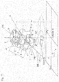
- For example, as shown in
Fig. 15 , it is assumed that aparallel link mechanism 1 is mounted on anXY stage 34 in a suspended manner, and a target workpiece W having a rectangular parallelepiped is placed on a work table 39 which is a Z-axis stage. It is noted that the configuration of the link actuation device shown inFig. 15 is basically the same as that described later inFig. 2 . In such a configuration, the following method may be generally used for causing theend effector 29 to act on the entire periphery of the side surface of the rectangular parallelepiped target workpiece W. - For the purpose of explaining the operation of the configuration shown in
Fig. 15, Fig. 16 shows the positional relationship between the target workpiece and the parallel link mechanism when the configuration shown inFig. 15 is seen from above. First, the XY stage 33 (Fig. 15 ) is moved to a position (i), and theparallel link mechanism 1 is moved to a position where theend effector 29 indicates point (a) on the side surface of the workpiece. Thereafter, theend effector 29 is activated, and at the same time, only the linear motion mechanism 31 (here, the Y axis of the XY stage 34) is moved to a position (ii) while theparallel link mechanism 1 is kept fixed. Then, after the movement to the position (ii) is completed, theend effector 29 is stopped. Secondly, the XY stage is moved to a position (iii), and theparallel link mechanism 1 is moved to a position where theend effector 29 indicates point (b) on the side surface of the workpiece. - Thereafter, the
end effector 29 is activated again, and at the same time, only the linear motion mechanism 31 (, X-axis stage 33) is moved to a position (iv) while theparallel link mechanism 1 is kept fixed. After the movement to the position (iv) is completed, theend effector 29 is stopped. The same operation is repeated in the order of (v), (vi), (vii), (viii), whereby theend effector 29 can be caused to act on the entire periphery of the side surface of the rectangular parallelepiped target workpiece W. - In this method, since the
end effector 29 is activated and stopped during a series of operations, a joint (discontinuity) by theend effector 29 occurs at the boundary part of the side surface. Accordingly, it is desired that, in the series of operations, at the time of movement at each corner, theparallel link mechanism 1 and thelinear motion mechanism 31 are operated while theend effector 29 remains activated without being stopped. At this time, for example, at the corner of point (b), theXY stage 34 performs an arc interpolation movement from (ii) to (iii) with a central angle of 90° about point (b), and at the same time, theparallel link mechanism 1 is turned by 90° such that theend effector 29 indicates point (b). As a result, theend effector 29 continues acting at the point (b) during the time period in which thelinear motion mechanism 31 and theparallel link mechanism 1 move from (ii) to (iii), and thus theend effector 29 acts excessively on the corner of point (b). - In any of the above methods, in the case of performing laser processing, coating by a dispenser or ink jetting, or welding, processing unevenness, coating unevenness, or thickness unevenness in welding may be caused.
- In order to solve the above problem, an object of the present invention is to provide control device for a link actuation device and a control method for a link actuation device with which, in a work device in which a parallel link mechanism and a linear motion mechanism are combined, the end effector can perform working on the boundary surface having a sharp angle on the surface of a target workpiece while moving at a substantially constant speed at the boundary surface, and thus can perform working without generating unevenness on the boundary surface. Hereinafter, the summary of the present invention will be described using reference characters in the drawings showing embodiments.
- A control device for a link actuation device according to the present invention is operable to control the
link actuation device 41 in which aparallel link mechanism 1 and alinear motion mechanism 31 are combined and which performs working by causing anend effector 29 to continuously act along a line L extending over a boundary surface B at a corner on a flat work surface S of a target workpiece W. Theparallel link mechanism 1 has a structure in which a distal-end-side link hub 3, to which theend effector 29 is mounted, is connected to a proximal-end-side link hub 2 via three ormore link mechanisms 4 such that a posture of the distal-end-side link hub 3 is changeable relative to the proximal-end-side link hub 2, and theparallel link mechanism 1 includes a plurality ofactuators 53 to 55 for changing the posture of the distal-end-side link hub 3. - The
linear motion mechanism 31 has a function of linearly moving in two-axis directions or three-axis directions orthogonal to each other by being driven byactuators 35 to 37, and thelinear motion mechanism 31 is provided so as to move the proximal-end-side link hub 2 of theparallel link mechanism 1 or move the target workpiece W. Thecontrol device 61 includes: aline storage 64 configured to store the line L as line segment data; anoperation command generator 65 configured to generate an operation command for operating theparallel link mechanism 1 and thelinear motion mechanism 31, on the basis of the stored line L; and acontroller 66 configured to control theactuators 35 to 37 of thelinear motion mechanism 31 and theparallel link mechanism 1 in accordance with the generated operation command. - The
operation command generator 65 includes: anarea division unit 67 configured to divide the line L on the flat work surface S into a straight area LS and a corner area LC, using the boundary surface B as a reference, in accordance with a predetermined rule; a straight area operationcommand generation unit 68 configured to generate a command for operating only thelinear motion mechanism 31 while keeping the posture of theparallel link mechanism 1 fixed, in the straight area LS; and a corner area operationcommand generation unit 69 configured to generate a command so that an acting point P of theend effector 29 passes on the boundary surface B at a substantially constant speed by thelinear motion mechanism 31 and theparallel link mechanism 1 performing coordinated operations in the corner area LC. - In the control device configured as described above, in operation in which the
end effector 29 is caused to continuously act along the line L extending over the boundary surface B which is located at a corner on the flat work surface S of the target workpiece W and thus has a sharp angle, thearea division unit 67 divides the line L into the straight area LS and the corner area LC. - In the straight area LS, only the
linear motion mechanism 31 is operated while theparallel link mechanism 1 is kept fixed in a desired posture. In the corner area LC, thelinear motion mechanism 31 and theparallel link mechanism 1 are controlled so as to perform coordinated operations so that the acting point P of theend effector 29 passes on the boundary surface B at a substantially constant speed. - Thus, in the operation in which the
end effector 29 continuously acts on the boundary surface B having a sharp angle on the flat work surface S, the acting point P of theend effector 29 can move at a substantially constant speed, whereby unevenness in working by theend effector 29 can be eliminated. In the case where, as theend effector 29, a laser, a dispenser, an ink jet device, a welding device, or the like is attached to the link to perform working, it is possible to eliminate unevenness of laser processing, unevenness of coating by the dispenser or the ink jet device, or unevenness of welding by the welding device. - Since division into the straight area LS and the corner area LC is performed and coordinated operations are performed in only the corner area LC, a command for performing the coordinated operations can be generated efficiently and in a short time. In the straight area LS, of the
parallel link mechanism 1 and thelinear motion mechanism 31, only thelinear motion mechanism 31 is operated, and therefore, it is possible to perform operation at high speed. Also, since the posture of theend effector 29 is not changed, there is an advantage in terms of working quality. - A specific example of a method for performing the coordinated operations is as follows. First, a path from a start point A to an end point E of the corner area LC is divided into a plurality of sections by passing points F. The position of the
linear motion mechanism 31 and the posture of theparallel link mechanism 1 in each section are set so that the angle at which theend effector 29 acts will change smoothly. At this time, the change in the angle at which theend effector 29 acts is set to be small enough that the quality after theend effector 29 acts is not influenced. The movement amounts (X, Y, Z) of the linear motion mechanism 31 (XYZ stage) in each divided section, and the movement amounts (β1, β2, β3) of theactuators 53 to 55 composing theparallel link mechanism 1, are calculated. - Secondly, the movement speeds of the
actuators 35 to 37, 53 to 55 in each section are calculated from a movement period in the section determined by a specified target movement speed (speed of tracing the side surface of the workpiece) and the distance of the section, and the movement amounts of theactuators 35 to 37, 53 to 55 in the section. By continuously positioning theactuators 35 to 37, 53 to 55 without acceleration or deceleration in each divided section, theend effector 29 moves at a substantially constant speed from the start point A to the end point E of the corner area LC. The "substantially constant speed" is, in other words, "approximately constant speed", and means that the speed is hardly changed so that the speed can be regarded as constant speed in terms of working by theend effector 29. At a joint between the corner area LC and the straight area LS, continuous operation is similarly performed without acceleration or deceleration. Thus, in the case of performing laser processing, coating by a dispenser or ink jet, or welding, it is possible to eliminate processing unevenness, coating unevenness, or thickness unevenness in welding on the boundary surface B. - The above specific method for coordinated operations may be implemented as follows. For example, the corner area operation
command generation unit 69 divides a path from a start point A to an end point E of the corner area LC into a specified number of sections by passing points F; calculates movement amounts X, Y, Z of thelinear motion mechanism 31 in each divided section, and movement amounts β1, β2, β3 of theactuators 53 to 55 composing theparallel link mechanism 1; calculates movement speeds of theactuators 35 to 37, 53 to 55 in each section, on the basis of a movement period in each section determined by the specified target movement speed and the distance of the section, and the movement amounts β1, β2, β3, X, Y, Z of theactuators 53 to 55, 35 to 37 in the section; and generates a command for continuously positioning eachactuator 35 to 37, 53 to 55 without acceleration or deceleration, in each divided section. - The
area division unit 67 may calculate a size of the corner area LC, on the basis of a speed limit of thelinear motion mechanism 31 and a movement speed of thelinear motion mechanism 31 calculated from each divided passing point F and the specified target movement speed in the corner area operationcommand generation unit 69. Thus, it is possible to calculate an appropriate size of the corner area LC that allows desired coordinated operations. - The
area division unit 67 may include a table TB indicating a relationship between a size of the corner area LC and a specified target movement speed, and may calculate the size of the corner area LC from the target movement speed by using the table TB. Such a configuration also makes it possible to calculate an appropriate size of the corner area LC that allows desired coordinated operations. - The
operation command generator 65 may perform the generation of the operation command based on the line segment data of the line L, at the time of operation of thelink actuation device 41, e.g., immediately before operation in each section, or simultaneously with the operation. Alternatively, theoperation command generator 65 may calculate settings (e.g., operation commands) for all the sections in the corner area LC before thelink actuation device 41 actually operates, and may store the settings into anoperation command storage 70, and thecontroller 66 may perform control by reading the settings corresponding to the sections from theoperation command storage 70, at a time of operating thelink actuation device 41. In this case, theoperation command generator 65 and thecontroller 66 may be formed by physically separated computers or the like, and the generated operation commands may be stored, online or offline, into theoperation command storage 70 provided on thecontroller 66 side. - The flat work surface S to be worked by the
end effector 29 may be an outer peripheral surface of a rectangular parallelepiped, or may be an inner peripheral surface thereof. In the case where such an outer peripheral surface or an inner peripheral surface of a rectangular parallelepiped is the flat work surface S, the effect of the present invention that working can be performed without unevenness is more effectively exerted. - A control method for a link actuation device according to the present invention is operable to control the
link actuation device 41 configured as described above, the method including: dividing the line L on the flat work surface S into a straight area LS and a corner area LC, using the boundary surface B as a reference, in accordance with a predetermined rule; operating only thelinear motion mechanism 31 while keeping the posture of theparallel link mechanism 1 fixed, in the straight area LS; and performing operation so that an acting point P of theend effector 29 passes on the boundary surface B at a substantially constant speed by thelinear motion mechanism 31 and theparallel link mechanism 1 performing coordinated operations in the corner area LC. Desirably, the above control method may further include: storing the line L as line segment data; generating an operation command for operating theparallel link mechanism 1 and thelinear motion mechanism 31, on the basis of the stored line L; and controlling theactuators 35 to 37 of thelinear motion mechanism 31 and theparallel link mechanism 1 in accordance with the generated operation command. - In the above control method, as in the control device of the present invention described above, the
end effector 29 can perform working on the boundary surface B having a sharp angle on the surface of the target workpiece, while moving at a substantially constant speed at the boundary surface B, and thus can perform working without generating unevenness on the boundary surface B. - Any combination of at least two constructions, disclosed in the appended claims and/or the specification and/or the accompanying drawings should be construed as included within the scope of the present invention. In particular, any combination of two or more of the appended claims should be equally construed as included within the scope of the present invention.
- In any event, the present invention will become more clearly understood from the following description of preferred embodiments thereof, when taken in conjunction with the accompanying drawings. However, the embodiments and the drawings are given only for the purpose of illustration and explanation, and are not to be taken as limiting the scope of the present invention in any way whatsoever, which scope is to be determined by the appended claims. In the accompanying drawings, like reference numerals are used to denote like parts throughout the several views, and:
-
Fig. 1 illustrates the conceptual configuration of a control device for a link actuation device according to an embodiment of the present invention; -
Fig. 2 is a front view of the link actuation device to be controlled by the control device; -
Fig. 3 is a partial perspective view showing areas of a target workpiece; -
Fig. 4 is a plan view showing areas of the target workpiece; -
Fig. 5 is a flowchart of calculation of a corner length by the control device for the link actuation device; -
Fig. 6 is a plan view showing areas of a target workpiece in another example; -
Fig. 7 is a perspective view of a parallel link mechanism of the link actuation device; -
Fig. 8 is a front view showing a partial link mechanism of the parallel link mechanism; -
Fig. 9A illustrates operation of the parallel link mechanism, and shows the link mechanism before the posture thereof is changed; -
Fig. 9B illustrates the operation of the parallel link mechanism, and shows the link mechanism after the posture thereof is changed; -
Fig. 10 shows a straight-line model of the parallel link mechanism; -
Fig. 11 is an enlarged sectional view of a part of the parallel link mechanism; -
Fig. 12 is a calculation flowchart for obtaining the posture of a distal-end-side link hub (bend angle θ, turning angle ϕ) on the basis of three-dimensional orthogonal coordinates; -
Fig. 13 is a perspective view of the parallel link mechanism shown inFig. 7 , with other dimension lines provided thereto; -
Fig. 14 illustrates the case of performing operation in a point-to-point manner on the flat work surface; -
Fig. 15 is a front view of a link actuation device; and -
Fig. 16 illustrates operation in a conventional link actuation device. - An embodiment of the present invention will be described with reference to the drawings. This
control device 61 for a link actuation device is operable to control alink actuation device 41 in which aparallel link mechanism 1 and alinear motion mechanism 31 are combined, and is applied to the case of performing working while causing theend effector 29 to continuously act along a line L extending over a boundary surface B at a corner on a flat work surface of a target workpiece W. - As shown in
Fig. 2 , in theparallel link mechanism 1, a distal-end-side link hub 3 to which theend effector 29 is mounted is connected to a proximal-end-side link hub 2 via threelink mechanisms 4 such that the posture of the distal-end-side link hub 3 is changeable relative to the proximal-end-side link hub 2, and a plurality ofactuators link mechanism 4 so as to change the posture of the distal-end-side link hub 3. - The
linear motion mechanism 31 has a function of linearly moving the target workpiece W in three-axis directions orthogonal to each other. In the present embodiment, thelinear motion mechanism 31 includes: a link-side linearmotion mechanism portion 31A for moving the target workpiece W in two-axis directions along X axis and Y axis; and a workpiece-side linearmotion mechanism portion 31B for moving the target workpiece W in the Z-axis direction. The X axis, Y axis, and Z axis are along the right-left direction, the front-rear direction, and the up-down direction, respectively, and are orthogonal to each other. - The link-side linear
motion mechanism portion 31A includes anX stage 33 provided at a top portion of amount 32 so as to be movable in the X-axis direction, and anXY stage 34 provided to theX stage 33 so as to be movable in the Y-axis direction. The proximal-end-side link hub 2 located at the upper end in theparallel link mechanism 1 is connected to theXY stage 34, and theparallel link mechanism 1 is mounted so as to be directed downward. TheX stage 33 and theXY stage 34 are driven to move forward/backward relative to themount 32 and theX stage 33, by X-axis and Y-axis actuators - The workpiece-side linear
motion mechanism portion 31B is provided below the area where theparallel link mechanism 1 operates, and includes a work table 39 which is driven to be lifted/lowered by a Z-axis actuator 37 such as a motor via a lifting/loweringmechanism 38. The target workpiece W is to be placed on the work table 39. - The
end effector 29 is operable to perform working on the target workpiece W, in, for example, a contactless manner, and is a laser for laser processing, a dispenser for coating, an ink-jet nozzle, a welding torch, or the like. - A specific example of the
parallel link mechanism 1 will be described with reference toFig. 7 to Fig. 11 .Fig. 9A and Fig. 9B are front views respectively showing different states of theparallel link mechanism 1. Theparallel link mechanism 1 is formed by connecting the distal-end-side link hub 3 to the proximal-end-side link hub 2 via the threelink mechanisms 4 such that the posture of the distal-end-side link hub 3 is changeable relative to the proximal-end-side link hub 2.Fig. 9A and Fig. 9B show only onelink mechanism 4. -
Fig. 7 is a perspective view showing theparallel link mechanism 1 three-dimensionally. Each of the threelink mechanisms 4 includes a proximal-end-sideend link member 5, a distal-end-sideend link member 6, and acenter link member 7, and thus, forms a trinodal chain link mechanism composed of four revolute pairs. The proximal-end-side and distal-end-sideend link members side link hub 2 and the distal-end-side link hub 3. Thecenter link member 7 has one end to which the distal end of the proximal-end-sideend link member 5 is rotatably connected, and the other end to which the distal end of the distal-end-sideend link member 6 is rotatably connected. - The proximal-end-side and distal-end-side
end link members Fig. 9A ) of the threelink mechanisms 4 coincide with each other. In addition, a distance d between the spherical link centers PA, PB is also the same among the threelink mechanisms 4. The center axes of the revolute pairs between theend link members center link member 7 may have a certain crossing angle γ, or may be parallel. - That is, the three
link mechanisms 4 have a geometrically identical shape. The geometrically identical shape means that a geometric model representing thelink members center link member 7 are symmetric.Fig. 10 is a diagram representing onelink mechanism 4 by straight lines. - Each
link mechanism 4 of the present embodiment is a rotationally symmetric type, so that the positional relationship between a proximal side region composed of the proximal-end-side link hub 2 and the proximal-end-sideend link member 5, and a distal side region composed of the distal-end-side link hub 3 and the distal-end-sideend link member 6, is rotationally symmetric with respect to a center line C of thecenter link member 7.Fig. 9A shows a state in which a center axis QA of the proximal-end-side link hub 2 and a center axis QB of the distal-end-side link hub 3 are on the same line, andFig. 9B shows a state in which the center axis QB of the distal-end-side link hub 3 has a predetermined operating angle relative to the center axis QA of the proximal-end-side link hub 2. Even when the posture of eachlink mechanism 4 is changed, the distance d between the proximal-end-side and distal-end-side spherical link centers PA, PB does not change. - The proximal-end-
side link hub 2, the distal-end-side link hub 3, and the threelink mechanisms 4 cooperate together to form a mechanism having two degrees of freedom that allows the distal-end-side link hub 3 to move in orthogonal two-axis directions relative to the proximal-end-side link hub 2. In other words, this mechanism is operable to allow the posture of the distal-end-side link hub 3 to be changed relative to the proximal-end-side link hub 2 at two degrees of freedom in rotation. In this mechanism having two degrees of freedom, the distal-end-side link hub 3 is changed in its posture relative to the proximal-end-side link hub 2 about an intersection P among the center axis QA of the proximal-end-side link hub 2, the center axis QB of the distal-end-side link hub 3, and the center line C of thecenter link member 7. - In this mechanism having two degrees of freedom, the movable range of the distal-end-
side link hub 3 relative to the proximal-end-side link hub 2 can be set to be wide, in spite of its compact size. For example, the maximum value (maximum bend angle) of a bend angle θ (Fig. 7 ) between the center axis QA of the proximal-end-side link hub 2 and the center axis QB of the distal-end-side link hub 3 can be about ±90°. In addition, a turning angle ϕ of the distal-end-side link hub 3 relative to the proximal-end-side link hub 2 can be set within a range of 0° to 360°. The bend angle θ is a vertical angle at which the center axis QB of the distal-end-side link hub 3 is tilted relative to the center axis QA of the proximal-end-side link hub 2. The turning angle ϕ is a horizontal angle at which the center axis QB of the distal-end-side link hub 3 is tilted relative to the center axis QA of the proximal-end-side link hub 2. - This
parallel link mechanism 1 can be configured such that shaft members 13 (Fig. 8 ) of theend link members link mechanism 4 are equal in angle and length, the proximal-end-sideend link member 5 and the distal-end-sideend link member 6 are equal in geometric shape, and the proximal end side and the distal end side of thecenter link member 7 have equal shapes. At this time, if the angular positional relationship between thecenter link member 7 and theend link members center link member 7, due to the geometric symmetry, the proximal side region composed of the proximal-end-side link hub 2 and the proximal-end-sideend link member 5, and the distal side region composed of the distal-end-side link hub 3 and the distal-end-sideend link member 6, move in the same manner. For example, in the case where rotation shafts are provided in the proximal-end-side and distal-end-side link hubs center link member 7 in this equal-speed rotation is referred to as constant velocity bisecting plane. - Therefore, by arranging, on the circumference, a plurality of
link mechanisms 4 sharing the proximal-end-side link hub 2 and the distal-end-side link hub 3 and having the same geometric shape, as positions that allow the plurality oflink mechanisms 4 to move compatibly with each other, thecenter link members 7 are limited to move on only their respective constant velocity bisecting planes. Thus, even when the proximal end side and the distal end side have any operating angles, the proximal end side and the distal end side rotate at equal speeds. - The proximal-end-
side link hub 2 and the distal-end-side link hub 3 each have a through hole 10 (Fig. 11 ) formed along the axial direction, at the center part, and have a doughnut shape whose outer shape is spherical. The center axes of the throughholes 10 coincide with the respective center axes QA, QB of thelink hubs side link hub 2 and the distal-end-side link hub 3, the proximal-end-sideend link members 5 and the distal-end-sideend link members 6 are rotatably connected thereto, respectively. -
Fig. 11 is a sectional view showing a revolute pair between the proximal-end-side link hub 2 and the proximal-end-sideend link member 5, and a revolute pair between the proximal-end-sideend link member 5 and thecenter link member 7. The proximal-end-side link hub 2 has, at three locations along the circumferential direction, communication holes 11 which extend in the radial direction and through which the axial-direction throughhole 10 and the outer circumferential side communicate with each other. Eachshaft member 13 is rotatably supported by twobearings 12 provided in thecommunication hole 11. An outer end of theshaft member 13 protrudes from the proximal-end-side link hub 2, and has a protrudingscrew portion 13a to which the proximal-end-sideend link member 5 is joined and fastened by anut 14 being tightened. - Each bearing 12 is a rolling bearing such as a deep groove ball bearing, for example, and has an outer ring fitted to the inner circumference of the
communication hole 11, and an inner ring (not shown) fitted to the outer circumference of theshaft member 13. The outer ring is prevented from coming off, by a retainingring 15. Aspacer 16 is interposed between the inner ring and the proximal-end-sideend link member 5. The tightening force of thenut 14 is transferred to the inner ring via the proximal-end-sideend link member 5 and thespacer 16, so as to apply a predetermined preload to thebearings 12. - In the revolute pair between the proximal-end-side
end link member 5 and thecenter link member 7, twobearings 19 are provided in each of communication holes 18 formed at both ends of thecenter link member 7, and ashaft portion 20 defined at the distal end of the proximal-end-sideend link member 5 is rotatably supported by thebearings 19. Thebearings 19 are fixed via aspacer 21 by anut 22 being tightened. - Each bearing 19 is a rolling bearing such as a deep groove ball bearing, for example, and has an outer ring (not shown) fitted to the inner circumference of the
communication hole 18, and an inner ring (not shown) fitted to the outer circumference of theshaft portion 20. The outer ring is prevented from coming off, by a retainingring 23. A tightening force of thenut 22 screwed to a tipend screw portion 20a of theshaft portion 20 is transferred to the inner ring via thespacer 21, so as to apply a predetermined preload to thebearings 19. - Thus, the revolute pair between the proximal-end-
side link hub 2 and the proximal-end-sideend link member 5, and the revolute pair between the proximal-end-sideend link member 5 and thecenter link member 7, have been described above. The same configuration applies also to the revolute pair between the distal-end-side link hub 3 and the distal-end-sideend link member 6, and the revolute pair between the distal-end-sideend link member 6 and the center link member 7 (not shown). - As described above, the
bearings link mechanism 4, i.e., the revolute pair between the proximal-end-side link hub 2 and the proximal-end-sideend link member 5, the revolute pair between the distal-end-side link hub 3 and the distal-end-sideend link member 6, the revolute pair between the proximal-end-sideend link member 5 and thecenter link member 7, and the revolute pair between the distal-end-sideend link member 6 and thecenter link member 7. Thus, frictional resistance in each revolute pair is reduced, whereby rotational resistance can be reduced, so that smooth power transmission can be ensured, and also, durability can be improved. - In the
parallel link mechanism 1 shown inFig. 8 , the proximal-end-side link hub 2 is fixed to the lower surface of theXY stage 34, and the distal-end-side link hub 3 is provided in a suspended state. Theactuator 53, which is formed from a motor or another rotary actuator, is provided on the upper surface of theXY stage 34. InFig. 8 , onelink mechanism 4 is shown, but also for the other twolink mechanisms 4, theactuators respective link mechanisms 4 in the same manner as described below. Anoutput shaft 53a of theactuator 53 penetrates theXY stage 34 so as to protrude downward, and abevel gear 57 attached to theoutput shaft 53a and a sector-shapedbevel gear 58 attached to theshaft member 13 of the proximal-end-side link hub 2 are engaged with each other. - When the
actuator 53 is rotated, the rotation is transferred to theshaft member 13 via the pair ofbevel gears end link member 5 relative to the proximal-end-side link hub 2 is changed. Through control of the operation amount of each actuator 53, the angle of the proximal-end-sideend link member 5 is adjusted for theindividual link mechanism 4, whereby the posture (hereinafter, referred to as "distal end posture") of the distal-end-side link hub 3 relative to the proximal-end-side link hub 2 is determined. The operation of each actuator 53 to 55 is controlled by thecontrol device 61 shown inFig. 1 . - As shown in
Fig. 1 , thecontrol device 61 includes: acommand generation unit 62 for generating an operation command on the basis of line segment data of the line L on the flat work surface S of the target workpiece W,; and acontrol unit 63 for controlling thelink actuation device 41 in accordance with the generated operation command. Thecommand generation unit 62 and thecontrol unit 63 may be provided in one computer or the like so as to be conceptually discriminated from each other, or may be provided in separate devices such as computers different from each other and may be connected to each other online or configured to be able to pass and receive data via a storage medium or the like, offline. In the case where thecommand generation unit 62 and thecontrol unit 63 are separate devices, they may be provided at remote locations separated from each other. - The
control unit 63 includes acontroller 66 and anoperation command storage 70. Thecontroller 66 is operable to control theactuators parallel link mechanism 1 and theactuators linear motion mechanism 31 in accordance with the generated operation command, and is, as it were, a numerical control device. Thecontroller 66 performs position control and speed control for theactuators parallel link mechanism 1 and theactuators linear motion mechanism 31, in a point-to-point manner, for example. Theoperation command storage 70 is operable to store an operation command to be executed by thecontroller 66 and to store an operation command generated by thecommand generation unit 62. It is noted that, in the case where thecommand generation unit 62 and thecontrol unit 63 are provided separately from each other, such a storage may be provided in each of both units so that operation commands can be transferred therebetween. - The
command generation unit 62 includes aline storage 64 and anoperation command generator 65. - The
line storage 64 stores the line L as numerical line segment data. The line segment data stored in theline storage 64 is data of a plurality of line segments which are sequentially connected to each other, for example, and is composed of three-dimensional coordinates indicating a start point and an end point of each line segment. The line segment data stored in theline storage 64 may further include data for identifying the line shape, indicating, for example, whether the line segment is a straight line or a curve, or the like. - The
operation command generator 65 is operable to generate operation commands for operating theparallel link mechanism 1 and thelinear motion mechanism 31, on the basis of the line segment data of the line L stored in theline storage 64. Theoperation command generator 65 includes anarea division unit 67, a straight area operationcommand generation unit 68, and a corner areaoperation command unit 69. - The
area division unit 67 is operable to divide the line L on the flat work surface S into a straight area LS and a corner area LC using a boundary surface B as a reference, in accordance with a predetermined rule. The straight area operationcommand generation unit 68 is operable to generate a command for operating only thelinear motion mechanism 31 while keeping the posture of theparallel link mechanism 1 fixed, in the straight area LS. The corner area operationcommand generation unit 69 is operable to generate a command so that an acting point P of theend effector 29 passes on the boundary surface B at a substantially constant speed through coordinate operations of thelinear motion mechanism 31 and theparallel link mechanism 1 in the corner area LC. - The
area division unit 67 may calculate the size of the corner area LC on the basis of, as the above rule, the speed limit of thelinear motion mechanism 31 and the movement speed of thelinear motion mechanism 31 calculated from each divided passing point F and a target movement speed specified by the corner area operationcommand generation unit 69, for example. Thus, it is possible to calculate an appropriate size of the corner area LC that allows desired coordinated operations to be performed. Alternatively, thearea division unit 67 may have a table TB indicating the relationship between the size of the corner area LC and a specified target movement speed, and may calculate the size of the corner area LC from the target movement speed, using the table TB. - The corner area operation
command generation unit 69 divides a path from a start point A to an end point E of the corner area LC into a specified number of sections by passing points F, for example. The corner area operationcommand generation unit 69 calculates movement amounts X, Y, Z of thelinear motion mechanism 31 in each divided section, and movement amounts β1, β2, β3 of theactuators 53 to 55 composing theparallel link mechanism 1. Furthermore, the corner area operationcommand generation unit 69 calculates movement speeds of theactuators 35 to 37, 53 to 55 in each section, on the basis of a movement period in each section determined by the specified target movement speed and the distance of the section, and the movement amounts β1, β2, β3, X, Y, Z of theactuators 53 to 55, 35 to 37 in the section. The corner area operationcommand generation unit 69 generates a command for continuously positioning each actuator 35 to 37, 53 to 55 without acceleration or deceleration, in each divided section. - Further details of the functions of the
area division unit 67, the straight area operationcommand generation unit 68, and the corner area operationcommand generation unit 69 will be described together with a specific example of the control method below. - The case where the target workpiece W is a rectangular parallelepiped and the
end effector 29 is caused to act on the outer peripheral side surface of the target workpiece W, will be shown as an example.Fig. 4 shows a schematic diagram of the structure shown inFig. 2 , as seen from above. The outer peripheral line L on the side surface of the rectangular parallelepiped on which theend effector 29 acts, is divided into straight areas LS and corner areas LC (LC1 to LC4), and in each corner area LC, the path from a start point A to an end point E of the corner area LC is divided into a plurality of sections by passing points F. A circle plot enclosing a number represents coordinates (workpiece coordinates: WX, WY, WZ) at which theend effector 29 acts, in an orthogonal coordinate system of the target workpiece W, and a quadrangle plot enclosing a number represents coordinates (stage coordinates: SX, SY) where theXY stage 34 moves, in an orthogonal coordinate system of theXY stage 34. Here, the workpiece coordinate system and the stage coordinate system have origins at the same position. - Since the
parallel link mechanism 1 is mounted on theXY stage 34, an arrow from the quadrangle plot to the circle plot represents the direction in which theend effector 29 acts on the target workpiece W. The numbers in the circle plots and the quadrangle plots represent the order in which each actuator is positioned through a series of operations. The trajectory of theXY stage 34 is set to be a trajectory having an arc so that theXY stage 34 moves smoothly. - The
operation command generator 65 calculates, for each section, the movement amounts β1, β2, β3 of theactuators parallel link mechanism 1 and the movement amounts (X, Y, Z) for the respective axes of thelinear motion mechanism 31 at the time of movement in each divided section of the corner area LC. The relationship between the movement amounts in a three-dimensional orthogonal coordinate system (XYZ plane coordinate system) and the movement amounts β1, β2, β3 of theactuators 53 to 55 of theparallel link mechanism 1, will be described later. Theoperation command generator 65 calculates, for each section, the movement amounts β1, β2, β3 and the movement speed for each axis of thelinear motion mechanism 31 so that theend effector 29 passes around the side surface of the target workpiece W at a specified speed. The calculation method will be described later. - For example, in the case where a point A at which the operation is started is a start point A of the corner area LC1, the series of operations is as follows. First, the linear motion mechanism 31 (
XY stage 34, work table 39) and theparallel link mechanism 1 are moved so that theend effector 29 indicates the start point A of the corner area LC1. Then, theend effector 29 is activated, and at the same time, theactuators 53 to 55, 35 to 37 are continuously positioned without acceleration or deceleration, in each section by the movement amounts (β1, β2, β3, X, Y, Z) and the speeds calculated in advance, until reaching the end point E of thecorner area LC 1. - After movement to the end point E of the corner area LC1 is completed, only the X axis of the
linear motion mechanism 31 is moved to a start point A of the corner area LC2 while the posture of theparallel link mechanism 1 remains as it is. Here, at the joint between the corner area LC and the straight area LS, theactuators 53 to 55, 35 to 37 are continuously operated without acceleration or deceleration. Hereafter, the same operation as described above is repeated in the corner area LC2, the corner area LC3, and then the corner area LC4. When the action of theend effector 29 is completed to reach the start point A of the corner area LC1, theend effector 29 is stopped. - Here, the distance from the start point A (circle plot 1) of the corner area LC to the corner edge (circle plot 5), and the distance from the corner edge to the corner end point E (circle plot 9), are defined as "corner length". The
area division unit 67 calculates an optimum corner area LC by the following method. Here, the trajectory of theXY stage 34 in the corner area LC is set to be an arc (quadrangle plots 1 to 9) which passes from the start point A to the end point E of the corner area LC and has a center at the intersection of a line extending from the start point A of the corner area LC in the direction perpendicular to the workpiece side surface, and a line extending from the end point E of the corner area LC in the direction perpendicular to the workpiece side surface. The distance between theparallel link mechanism 1 and a target point P (seeFig. 2 ) is set to be an optimum distance that allows theend effector 29 to act on the target point. - If the corner length is short, the movement speed of the
XY stage 34 might be excessively high at each corner, leading to occurrence of vibration at the corner. Therefore, through the procedure in the flowchart shown inFig. 5 , the corner area operationcommand generation unit 69 calculates an optimum corner length L. In calculation for the corner length L, the corner area operationcommand generation unit 69 defines the minimum corner length for reference, as Lint (step T1), and divides a path from the start point A to the end point E of the corner area LC with the corner length Lint, into a plurality of sections by passing points F (step 2). Here, the number of the divisions is defined as D, and D is a value provided as a calculation parameter in advance. - In step T1, the orthogonal coordinates at the n-th point (n: natural number) on the target workpiece W among the division points are defined as (WXn, WYn), and the workpiece orthogonal coordinates at the (n+1)-th point are defined as (WXn+1, WYn+1). Similarly, the orthogonal coordinates at the n-th point for the stage among the division points are defined as (SXn, SYn), and the stage orthogonal coordinates at the (n+1)-th point are defined as (SXn+1, SYn+1). The corner area operation
command generation unit 69 calculates, for each section, movement amounts (SX, SY, WX, WY, WZ) of the stage coordinates and the workpiece coordinates, and on the basis of these calculated values and the specified target movement speed, calculates movement speeds of theX stage 33 and a Y stage (Y-axis direction of XY stage 34) at each point. In addition, the corner area operationcommand generation unit 69 sets Vmax to 0 in step T1, and sets n to 1 in step T2. - In step T3, the corner area operation
command generation unit 69 acquires the stage coordinates and the workpiece coordinates at each division point. Then, the corner area operationcommand generation unit 69 calculates a movement speed Vx of theX stage 33 by the following expression (7). The corner area operationcommand generation unit 69 calculates Vx for all the divided sections, and sets the maximum one of the calculated values Vx, as Vxmax (step T4 to T7).
[Math 1]
- Specifically, the corner area operation
command generation unit 69 compares the movement speed Vx of theX stage 33 calculated in step T3, with the maximum value Vxmax of the movement speed Vx of the X stage 33 (step T4). Then, if the movement speed Vx is greater than the maximum value Vxmax (Yes in step T4), the maximum value Vmax is set to Vx (step T5). Then, the corner area operationcommand generation unit 69 increments n to n+1 (step T6). If the movement speed Vx is equal to or smaller than the maximum value Vxmax (No in step T4), the corner area operationcommand generation unit 69 proceeds to step T6. - Then, the corner area operation
command generation unit 69 compares n with the number D of the divisions (step T7). If the number D of the divisions is greater than n (Yes in step T7), the process returns to step T3. If n is equal to or greater than the number D of the divisions (No in step T7), the process proceeds to step T8. - Thereafter, the corner area operation
command generation unit 69 compares Vxmax with a speed limit Vxlmt of theX stage 33 which is provided as a calculation parameter in advance (step T8). If Vxmax is greater than Vxlmt (Yes in step T8), that is, if the movement speed of theX stage 33 is greater than the speed limit of theX stage 33, the corner length L is set as L = L + Lplus (step T9), and the process returns to step T2, to divide again the path from the start point A to the end point E of the corner area LC with the corner length L, into a plurality of sections by passing points F. Lplus is an addition amount for the corner length, which is provided as a calculation parameter in advance. Hereafter, the same calculation as described above is performed, and then, the value of L when Vxmax becomes equal to or smaller than Vxlmt (No in step T8) is set as a final corner length Lx (step T10). - Also for the speed in the Y-axis direction of the
XY stage 34, the corner area operationcommand generation unit 69 performs calculation in the same manner as in the case ofX stage 33, to calculate a final corner length Ly. Then, the corner area operationcommand generation unit 69 compares Lx and Ly, and sets the greater one as a final corner length L. - The above configuration allows the acting point P of the
end effector 29 to move at a substantially constant speed in operation in which theend effector 29 continuously acts on the boundary surface B having a sharp angle on the flat work surface S, whereby unevenness in working by theend effector 29 can be eliminated. In the case where, as theend effector 29, a laser, a dispenser, an ink jet device, a welding device, or the like is attached to the link to perform working, it is possible to eliminate unevenness of laser processing, unevenness of coating by the dispenser or the ink jet device, or unevenness of welding by the welding device. - The
area division unit 67 makes division into the straight area LS and the corner area LC, and coordinated operations are performed in only the corner area LC. Therefore, a command for performing the coordinated operations can be generated efficiently and in a short time. In the straight area LS, of theparallel link mechanism 1 and thelinear motion mechanism 31, only thelinear motion mechanism 31 is operated, and therefore, it is possible to perform operation at high speed. Also, since the posture of theend effector 29 is not changed, there is an advantage in terms of working quality. -
Fig. 6 shows an example in which theend effector 29 is caused to act on the inner peripheral side surface of the rectangular parallelepiped, as the flat work surface S of the target workpiece W.Fig. 6 is a schematic view of the structure shown inFig. 2 , as seen from above. As in the case of the outer periphery shown inFig. 4 , thearea division unit 67 divides the inner peripheral line L on the rectangular parallelepiped into straight areas LS and corner areas LC (LC1 to LC4), and in each corner area LC, the corner area operationcommand generation unit 69 divides the path from a start point A to an end point E of the corner area LC into a plurality of sections by passing points F. - The coordinate positions on each axis of the
linear motion mechanism 31 for each division point is determined as follows, for example. The positions of thelinear motion mechanism 31 at the start point A (circle plot 1) and the end point E (circle plot 9) are located at positions (quadrangle plot 1, quadrangle plot 9) present on lines perpendicular to the side surface of the workpiece and extending in the directions in which theend effector 29 indicates the start point A and the end point E from the inner side. The position of the linear motion mechanism 31 (XY stage 34) at the corner edge point (circle plot 5) is located at a position (quadrangle plot 5) present on a bisector of the corner angle in the direction in which theend effector 29 indicates the corner edge point from the inner side. The distance between theparallel link mechanism 1 and each divided target point is set to be an optimum distance that allows theend effector 29 to act on the target point. - The positions of the linear motion mechanism 31 (XY stage 34) at points other than the start point A, the corner edge point (point on boundary surface B), and the end point E, are set on lines connecting the positions (
quadrangle plot 1,quadrangle plot 5, quadrangle plot 9) of the linear motion mechanism 31 (XY stage 34) at the start point A, the corner edge point, and the end point E. Each circle plot represents the coordinates (workpiece coordinates: WX, WY, WZ) at which theend effector 29 acts, in an orthogonal coordinate system of the workpiece, and each quadrangle plot represents coordinates (stage coordinates: SX, SY) where theXY stage 34 moves, in an orthogonal coordinate system of thelinear motion mechanism 31. Here, the workpiece coordinate system and the stage coordinate system have origins at the same position. An arrow from the quadrangle plot to the circle plot represents the direction in which theend effector 29 acts on the target workpiece. The numbers in the circle plots and the quadrangle plots represent the order in which each actuator is positioned through a series of operations. The series of operations and the corner length are the same as in the case of the outer peripheral side surface of the rectangular parallelepiped described with reference toFig. 4 . - Also in the case where the work surface S of the target workpiece W is the inner peripheral side surface of the rectangular parallelepiped as described above, as in the case of the outer peripheral surface, the
end effector 29 can perform working on the boundary surface B having a sharp angle on the surface of the target workpiece W, while moving at a substantially constant speed at the boundary surface B, and thus can perform working without generating unevenness on the boundary surface B. - The relationship between the movement amounts in a three-dimensional orthogonal coordinate system (XYZ plane coordinate system) and the movement amounts β1, β2, β3 of the
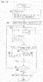
actuators 53 to 55 of theparallel link mechanism 1, will be described.Fig. 12 shows a calculation flowchart and calculation formulas for calculating the posture (bend angle θ, turning angle ϕ) of the distal-end-side link hub 3 on the basis of three-dimensional orthogonal coordinates (XYZ plane coordinates). The calculation in this flowchart is performed through convergence calculation by the method of least squares. - As shown in the following expression (1), where the distance between target coordinates T (x, y, z) and an origin O' of a plane at a height Z is denoted by r, r is calculated from the x, y coordinates of the target coordinates T.
[Math 2]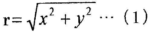
- Where the distance between the link spherical surface centers is denoted by d, the height from a reference plane to the proximal-end-side link spherical surface center is denoted by h, and the height of the target coordinates T is denoted by z, a height h' (see
Fig. 13 ) from the rotation center of the proximal-end-side link hub 2 to the target coordinates T is represented by expression (2).
[Math 3]
- Here, d and h are fixed values determined by link dimensions and device dimensions. Using the above expression (2), the distance between O' and the target coordinates T is calculated as r' by an expression relevant to θ as shown by expression (3). Therefore, the bend angle θ is obtained by searching for the bend θ that minimizes the difference between r (calculated from x, y of target coordinates T) and r' (calculated from bend angle θ) as shown in expression (4).
[Math 4]

- Using the above expressions, the value of θ that minimizes dr is searched for.
- The range of θ is 0° to less than 90°, and the maximum angle varies depending on the specifications of the link.
- The calculation flowchart shown in
Fig. 12 will be described. - First, r is calculated from expression (1) (step S1). Secondly, as initial setting for the calculation process, the present repetition number j is reset to zero, and an initial set value θ' for searching for the bend angle θ, and a searching repetition number N, are set. For example, θ' is set to be half the maximum bend angle. As the repetition number N increases, accuracy of the bend angle θ finally obtained increases, but the processing time for the calculation is prolonged. An optimum value of N is determined on the basis of the relationship between accuracy of the bend angle θ and the acceptable processing time.
- Then, with θ set as θ = θ', h', r ', and dr are calculated by expression (1) (step S2).
- In addition, here, θ' is set as θ'= θ'/2 (step S3).
- Thereafter, in step S4, determination as to dr is performed. If 0 < dr is satisfied, θ is set as θ = θ + θ' (step S5). If 0 > dr is satisfied, θ is set as θ = θ - θ' (step S6). Subsequently, j is incremented as j = j + 1 (step S7). If 0 = dr is satisfied, a solution Ansθ is set as θ = θ (step S9).
- In step S8, if the present repetition number j has not reached the set repetition number N yet, the process returns to step S3. This processing flow is repeated until the repetition number N is reached, and the finally obtained Ansθ is the calculated bend angle θ. After the bend angle is calculated, the turning angle is calculated as shown in expressions (5) and (6).
[Math 5]

- From the bend angle θ and the turning angle ϕ calculated as described above, a target distal end posture is determined. As described above, calculating the bend angle θ by performing search in order from the neighborhood of the present coordinate position as a reference through convergence calculation by the method of least squares, leads to decrease in the number of times of calculations.
- From the bend angle θ and the turning angle ϕ calculated as described above, a movement amount (hereinafter, referred to as "rotation angle") βn (n: 1 to 3) for operating each actuator 53 to 55 of the
parallel link mechanism 1 can be calculated as follows. The rotation angle βn is shown inFig. 13 which shows the sameparallel link mechanism 1 as that shown inFig. 7 , and several values necessary for the description are shown therein. The rotation angle βn is calculated by reversely converting the following expression (8), for example. The reverse conversion refers to conversion in which the rotation angle βn is calculated from the bend angle θ and the turning angle ϕ. The bend angle θ and the turning angle ϕ are mutually related with the rotation angle βn, and therefore, one value can be derived from the other values.
- Here, γ is the angle between the connection end axis of the
center link member 7 rotatably connected to the proximal-end-sideend link member 5, and the connection end axis of thecenter link member 7 rotatably connected to the distal-end-sideend link member 6. In addition, δn is a circumferential-direction separation angle of each proximal-end-sideend link member 5 relative to the proximal-end-sideend link member 5 as a reference. - It is noted that the rotation angle βn may be calculated by reversely converting expression (8) when necessary, or a table (not shown) indicating the relationship between the distal end position posture and the rotation angle βn may be prepared in advance.
- The movement speed will be described.
- The movement speed of the
parallel link mechanism 1 alone will be described. For the purpose of simplification, the description will be given using a plan view shown inFig. 14 . As shown inFig. 14 , in the operation in which theend effector 29 traces the points on the flat work surface S at a specified target movement speed V, the orthogonal coordinates at the n-th point are defined as (Xn, Yn), the orthogonal coordinates at the (n-1)-th point are defined as (Xn-1, Yn-1), and the movement amounts on β1 axis, β2 axis, and β3 axis from the (n-1)-th point to the n-th point are defined as Δβ1, Δβ2, Δβ3. Then, movement speeds V1n, V2n, V3n on the respective axes at the time of moving to the n-th point are represented by the following expression.
- In the case of combining the three axes (β1 axis, β2 axis, β3 axis) of the
parallel link mechanism 1, and thelinear motion mechanism 31, a combined speed Vn" when theend effector 29 moves along the points on the flat work surface S at a constant speed of V specified, will be described. Here, it is assumed that there is no movement in the Z-axis direction. As in the case ofFig. 14 , regarding the orthogonal coordinates of the target workpiece W, the orthogonal coordinates at the n-th point are defined as (Xn, Yn), and the orthogonal coordinates at the (n-1)-th point are defined as (Xn-1, Yn-1). Where the movement amounts on β1 axis, β2 axis, β3 axis, X axis, and Y axis from the (n-1)-th point to the n-th point are defined as Δβ1, Δβ2, Δβ3, Δx, and Δy, respectively, movement speeds V1n", V2n", V3n", Vxn", and Vyn" on the respective axes at the time of moving to the n-th point are represented by the following expression. The movement speeds on β1 axis, β2 axis, and β3 axis are movement speeds of the rotation angles.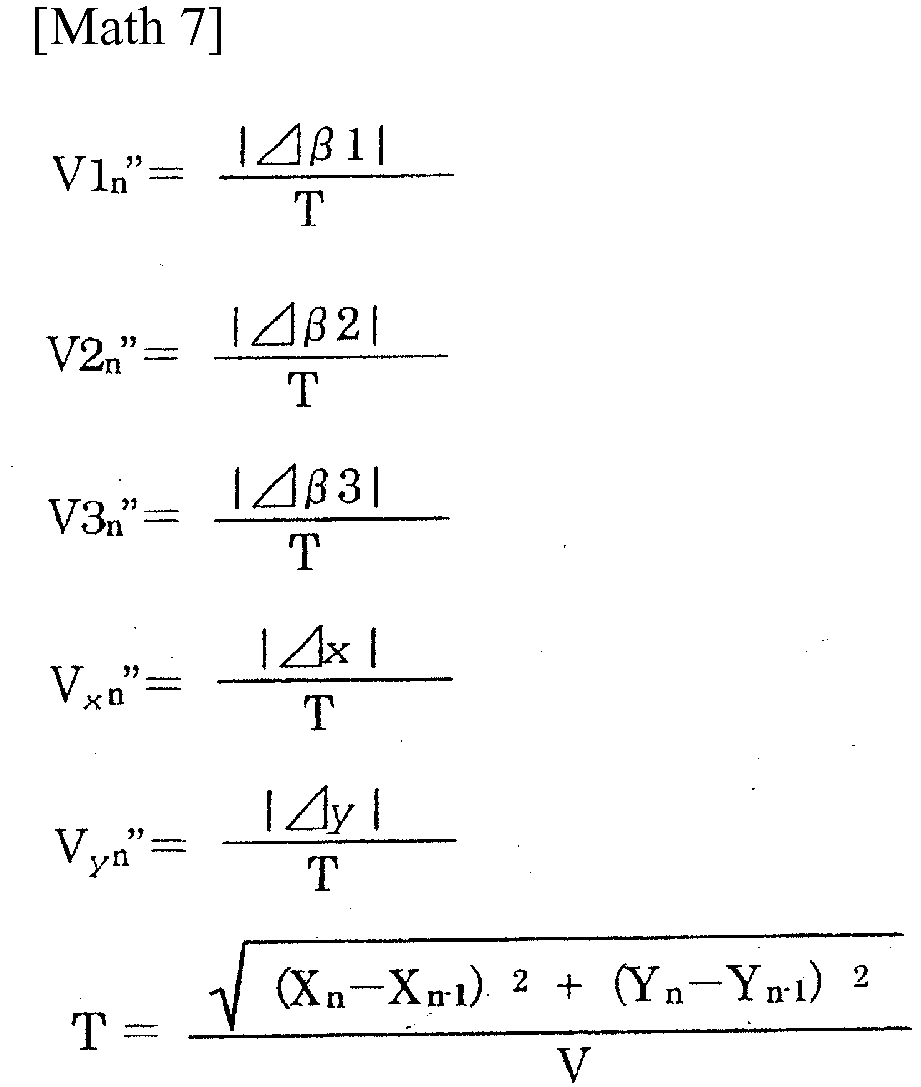
- As described above, the
control device 61 and the control method for the link actuation device according to the present embodiment allow theend effector 29 to perform working on the boundary surface B having a sharp angle on the surface of the target workpiece W, while moving at a substantially constant speed at the boundary surface B, and thus make it possible to perform working without generating unevenness on the boundary surface B. - Although the embodiments for carrying out the present invention have been described, the embodiments disclosed herein are illustrative in all aspects and not restrictive. The scope of the present invention is indicated by the claims, rather than by the above description, and is intended to include any modifications within the scope and meaning equivalent to the claims.
-
- 1
- parallel link mechanism
- 2
- proximal-end-side link hub
- 3
- distal-end-side link hub
- 4
- link mechanism
- 29
- end effector
- 31
- linear motion mechanism
- 32
- mount
- 33
- X stage
- 34
- XY stage
- 35 to 37
- actuator
- 39
- work table
- 41
- link actuation device
- 53 to 55
- actuator
- 61
- control device
- 66
- controller
- 67
- area division unit
- 68
- straight area operation command generation unit
- 69
- corner area operation command unit
- 70
- operation command storage
- L
- line
- S
- flat work surface
- W
- target workpiece
Claims (9)
- A control device for a link actuation device, the control device controlling the link actuation device in which a parallel link mechanism and a linear motion mechanism are combined and which performs working by causing an end effector to continuously act along a line extending over a boundary surface at a corner on a flat work surface of a target workpiece,
the parallel link mechanism having a structure in which a distal-end-side link hub, to which the end effector is mounted, is connected to a proximal-end-side link hub via three or more link mechanisms such that a posture of the distal-end-side link hub is changeable relative to the proximal-end-side link hub, and the parallel link mechanism including a plurality of actuators for changing the posture of the distal-end-side link hub,
the linear motion mechanism having a function of linearly moving in two-axis directions or three-axis directions orthogonal to each other by being driven by actuators, and the linear motion mechanism being provided so as to move the proximal-end-side link hub of the parallel link mechanism or move the target workpiece,
the control device comprising:a line storage configured to store the line as line segment data;an operation command generator configured to generate an operation command for operating the parallel link mechanism and the linear motion mechanism, on the basis of the stored line; anda controller configured to control the actuators of the linear motion mechanism and the parallel link mechanism in accordance with the generated operation command, whereinthe operation command generator includes:an area division unit configured to divide the line on the flat work surface into a straight area and a corner area, using the boundary surface as a reference, in accordance with a predetermined rule;a straight area operation command generation unit configured to generate a command for operating only the linear motion mechanism while keeping the posture of the parallel link mechanism fixed, in the straight area; anda corner area operation command generation unit configured to generate a command so that an acting point of the end effector passes on the boundary surface at a substantially constant speed by the linear motion mechanism and the parallel link mechanism performing coordinated operations in the corner area. - The control device for the link actuation device as claimed in claim 1, wherein the corner area operation command generation unit is configured to:to divide a path from a start point to an end point of the corner area into a specified number of sections by passing points;to calculate a movement amount of each actuator composing the parallel link mechanism and a movement amount of the linear motion mechanism in each divided section;to calculate a movement speed of each actuator in each section on the basis of the movement amount of the actuator of the section and a movement period in the section determined by a specified target movement speed and a distance of the section; andto generate the command so as to continuously position each actuator without acceleration or deceleration, in each divided section.
- The control device for the link actuation device as claimed in claim 2, wherein
the area division unit calculates a size of the corner area, on the basis of a speed limit of the linear motion mechanism and a movement speed of the linear motion mechanism calculated from each divided passing point and the specified target movement speed in the corner area operation command generation unit. - The control device for the link actuation device as claimed in claim 2, wherein
the area division unit includes a table indicating a relationship between a size of the corner area and a specified target movement speed, and calculates the size of the corner area from the target movement speed by using the table. - The control device for the link actuation device as claimed in any one claims 2 to 4, wherein
the operation command generator calculates settings for all the sections in the corner area before the link actuation device actually operates, and stores the settings into an operation command storage, and
the controller performs control by reading the settings corresponding to the sections from the operation command storage, at a time of operating the link actuation device. - The control device for the link actuation device as claimed in any one claims 1 to 5, wherein
the flat work surface to be worked by the end effector is an outer peripheral surface of a rectangular parallelepiped. - The control device for the link actuation device as claimed in any one claims 1 to 5, wherein
the flat work surface to be worked by the end effector is an inner peripheral surface of a rectangular parallelepiped. - A control method for a link actuation device, the control method controlling the link actuation device in which a parallel link mechanism and a linear motion mechanism are combined and which performs working by causing an end effector to continuously act along a line extending over a boundary surface at a corner on a flat work surface of a target workpiece,
the parallel link mechanism having a structure in which a distal-end-side link hub, to which the end effector is mounted, is connected to a proximal-end-side link hub via three or more link mechanisms such that a posture of the distal-end-side link hub is changeable relative to the proximal-end-side link hub, and the parallel link mechanism including a plurality of actuators for changing the posture of the distal-end-side link hub,
the linear motion mechanism having a function of linearly moving in two-axis directions or three-axis directions orthogonal to each other by being driven by actuators, and the linear motion mechanism being provided so as to move the proximal-end-side link hub of the parallel link mechanism or move the target workpiece,
the control method comprising:dividing the line on the flat work surface into a straight area and a corner area, using the boundary surface as a reference, in accordance with a predetermined rule;operating only the linear motion mechanism while keeping the posture of the parallel link mechanism fixed, in the straight area; andperforming operation so that an acting point of the end effector passes on the boundary surface at a substantially constant speed by the linear motion mechanism and the parallel link mechanism performing coordinated operations in the corner area. - The control method for the link actuation device as claimed in claim 8, further comprising:storing the line as line segment data;generating an operation command for operating the parallel link mechanism and the linear motion mechanism, on the basis of the stored line; andcontrolling the actuators of the linear motion mechanism and the parallel link mechanism in accordance with the generated operation command.
Applications Claiming Priority (2)
| Application Number | Priority Date | Filing Date | Title |
|---|---|---|---|
| JP2017033520A JP6800044B2 (en) | 2017-02-24 | 2017-02-24 | Link activator control device and control method |
| PCT/JP2018/006044 WO2018155444A1 (en) | 2017-02-24 | 2018-02-20 | Link operating device control device and control method |
Publications (3)
| Publication Number | Publication Date |
|---|---|
| EP3587041A1 true EP3587041A1 (en) | 2020-01-01 |
| EP3587041A4 EP3587041A4 (en) | 2020-12-23 |
| EP3587041B1 EP3587041B1 (en) | 2024-03-27 |
Family
ID=63253159
Family Applications (1)
| Application Number | Title | Priority Date | Filing Date |
|---|---|---|---|
| EP18757063.5A Active EP3587041B1 (en) | 2017-02-24 | 2018-02-20 | Link operating device control device and control method |
Country Status (5)
| Country | Link |
|---|---|
| US (1) | US11130229B2 (en) |
| EP (1) | EP3587041B1 (en) |
| JP (1) | JP6800044B2 (en) |
| CN (1) | CN110325326B (en) |
| WO (1) | WO2018155444A1 (en) |
Families Citing this family (5)
| Publication number | Priority date | Publication date | Assignee | Title |
|---|---|---|---|---|
| JP6719956B2 (en) * | 2016-04-20 | 2020-07-08 | Ntn株式会社 | Dual arm actuator |
| CN111093912B (en) * | 2017-09-08 | 2023-02-17 | Ntn株式会社 | Working device with parallel linkage mechanism |
| JP7579119B2 (en) * | 2020-11-20 | 2024-11-07 | Ntn株式会社 | Working Equipment |
| JP7666199B2 (en) * | 2021-07-30 | 2025-04-22 | セイコーエプソン株式会社 | Method for controlling robot system and robot system |
| JP2024011613A (en) * | 2022-07-15 | 2024-01-25 | 日鉄エンジニアリング株式会社 | control system |
Family Cites Families (18)
| Publication number | Priority date | Publication date | Assignee | Title |
|---|---|---|---|---|
| US5057758A (en) * | 1989-03-20 | 1991-10-15 | Hewlett-Packard Company | Passive payload for a cartridge handling system |
| US6330837B1 (en) * | 1997-08-28 | 2001-12-18 | Microdexterity Systems, Inc. | Parallel mechanism |
| JP2002096170A (en) * | 2000-09-19 | 2002-04-02 | Daihen Corp | Amendment method of automatic sensing process in automatic programming of arc welding robot |
| US6840127B2 (en) * | 2003-02-05 | 2005-01-11 | Michael Julius Moran | Tendon link mechanism with six degrees of freedom |
| JP2005144627A (en) * | 2003-11-18 | 2005-06-09 | Ntn Corp | Link operating device |
| DE602005026204D1 (en) * | 2004-10-21 | 2011-03-17 | Panasonic Corp | WELDING SYSTEM AND FIELD ELECTRODE WELDING PROCESS |
| WO2008108289A1 (en) * | 2007-03-01 | 2008-09-12 | Tokyo Institute Of Technology | Maneuvering system having inner force sense presenting function |
| US8897916B2 (en) * | 2007-03-01 | 2014-11-25 | Tokyo Institute Of Technology | Maneuvering system having inner force sense presenting function |
| CN101544020B (en) * | 2009-04-15 | 2011-05-11 | 上海中技桩业股份有限公司 | Preparation method for prestressed high-strength concrete pile |
| CN105269557B (en) * | 2012-03-23 | 2017-06-23 | Ntn株式会社 | Link actuation device |
| JP6324033B2 (en) * | 2013-11-22 | 2018-05-16 | Ntn株式会社 | Link actuator |
| JP6250372B2 (en) * | 2013-11-22 | 2017-12-20 | Ntn株式会社 | Automatic welding machine |
| JP6271288B2 (en) * | 2014-02-20 | 2018-01-31 | Ntn株式会社 | Control device and control method for link actuator |
| JP6482767B2 (en) * | 2014-03-27 | 2019-03-13 | Ntn株式会社 | Coating device |
| JP6453066B2 (en) * | 2014-12-05 | 2019-01-16 | Ntn株式会社 | Control method of link actuator |
| US9827678B1 (en) * | 2016-05-16 | 2017-11-28 | X Development Llc | Kinematic design for robotic arm |
| CN106425195B (en) * | 2016-08-29 | 2018-01-26 | 芜湖银星汽车零部件有限公司 | A kind of industrial welding robot |
| US10737817B2 (en) * | 2016-09-26 | 2020-08-11 | Yaskawa America, Inc. | Method, apparatus, and system for robotic article handling |
-
2017
- 2017-02-24 JP JP2017033520A patent/JP6800044B2/en active Active
-
2018
- 2018-02-20 WO PCT/JP2018/006044 patent/WO2018155444A1/en not_active Ceased
- 2018-02-20 CN CN201880013323.0A patent/CN110325326B/en active Active
- 2018-02-20 EP EP18757063.5A patent/EP3587041B1/en active Active
-
2019
- 2019-08-20 US US16/545,626 patent/US11130229B2/en active Active
Also Published As
| Publication number | Publication date |
|---|---|
| JP6800044B2 (en) | 2020-12-16 |
| US20190366535A1 (en) | 2019-12-05 |
| CN110325326A (en) | 2019-10-11 |
| JP2018138323A (en) | 2018-09-06 |
| WO2018155444A1 (en) | 2018-08-30 |
| CN110325326B (en) | 2022-11-01 |
| EP3587041B1 (en) | 2024-03-27 |
| US11130229B2 (en) | 2021-09-28 |
| EP3587041A4 (en) | 2020-12-23 |
Similar Documents
| Publication | Publication Date | Title |
|---|---|---|
| US11130229B2 (en) | Link operating device control device and control method | |
| EP3109010B1 (en) | Device and method for controlling link actuation device | |
| JP5426719B2 (en) | Robot system motion simulation device | |
| JP6453066B2 (en) | Control method of link actuator | |
| JP5374616B1 (en) | Tool path display device for displaying tool vectors of machine tools | |
| Farkhatdinov et al. | A preliminary experimental study on haptic teleoperation of mobile robot with variable force feedback gain | |
| JP5818987B2 (en) | Grooving method, machine tool control device, and tool path generation device | |
| JP6771288B2 (en) | Welding equipment and control method of welding equipment | |
| JP6145130B2 (en) | Trajectory display device that displays the trajectory of the tool axis | |
| CN105320059B (en) | The control device of servomotor | |
| JP2012152884A (en) | Machine tool control system | |
| WO2017043420A1 (en) | Composite work device using link operating device | |
| JP7140508B2 (en) | WORKING DEVICE USING PARALLEL LINK MECHANISM AND CONTROL METHOD THEREOF | |
| CN104999463B (en) | A kind of redundant mechanical arm motion control method based on configuration plane | |
| JP5792226B2 (en) | Inverse kinematic solution for multi-joint link mechanism and teaching data creation device using this inverse kinematic solution | |
| EP2845676B1 (en) | Program creating device for wire electric discharge machine | |
| JP4961447B2 (en) | NC machining equipment | |
| WO2016084685A1 (en) | Work apparatus using parallel link mechanism | |
| JP3710075B2 (en) | Weaving control device for welding robot | |
| Jeon et al. | Motion Control of Two Welding Mobile Robot with Seam Tracking Sensor | |
| CN118984762A (en) | Control devices for industrial equipment | |
| JPH06110534A (en) | Position control method for machine tools | |
| US11994835B2 (en) | Apparatus, controller, and method for generating image data of movement path of industrial machine | |
| JPH0683416A (en) | Robot controller with small figure processing unit | |
| Acikgoz et al. | Dynamic movement primitives and force feedback: Teleoperation in precision grinding process |
Legal Events
| Date | Code | Title | Description |
|---|---|---|---|
| STAA | Information on the status of an ep patent application or granted ep patent |
Free format text: STATUS: THE INTERNATIONAL PUBLICATION HAS BEEN MADE |
|
| PUAI | Public reference made under article 153(3) epc to a published international application that has entered the european phase |
Free format text: ORIGINAL CODE: 0009012 |
|
| STAA | Information on the status of an ep patent application or granted ep patent |
Free format text: STATUS: REQUEST FOR EXAMINATION WAS MADE |
|
| 17P | Request for examination filed |
Effective date: 20190816 |
|
| AK | Designated contracting states |
Kind code of ref document: A1 Designated state(s): AL AT BE BG CH CY CZ DE DK EE ES FI FR GB GR HR HU IE IS IT LI LT LU LV MC MK MT NL NO PL PT RO RS SE SI SK SM TR |
|
| AX | Request for extension of the european patent |
Extension state: BA ME |
|
| DAV | Request for validation of the european patent (deleted) | ||
| DAX | Request for extension of the european patent (deleted) | ||
| A4 | Supplementary search report drawn up and despatched |
Effective date: 20201123 |
|
| RIC1 | Information provided on ipc code assigned before grant |
Ipc: B25J 11/00 20060101ALI20201117BHEP Ipc: B25J 9/10 20060101AFI20201117BHEP Ipc: G05B 19/4093 20060101ALI20201117BHEP Ipc: B25J 9/00 20060101ALI20201117BHEP Ipc: B25J 9/16 20060101ALI20201117BHEP |
|
| STAA | Information on the status of an ep patent application or granted ep patent |
Free format text: STATUS: EXAMINATION IS IN PROGRESS |
|
| 17Q | First examination report despatched |
Effective date: 20220502 |
|
| REG | Reference to a national code |
Ref country code: DE Ref country code: DE Ref legal event code: R079 Ref document number: 602018067174 Country of ref document: DE Free format text: PREVIOUS MAIN CLASS: B25J0009100000 Ipc: B25J0005020000 |
|
| RIC1 | Information provided on ipc code assigned before grant |
Ipc: B25J 9/00 20060101ALI20230716BHEP Ipc: G05B 19/4093 20060101ALI20230716BHEP Ipc: B25J 9/16 20060101ALI20230716BHEP Ipc: B25J 5/02 20060101AFI20230716BHEP |
|
| GRAP | Despatch of communication of intention to grant a patent |
Free format text: ORIGINAL CODE: EPIDOSNIGR1 |
|
| STAA | Information on the status of an ep patent application or granted ep patent |
Free format text: STATUS: GRANT OF PATENT IS INTENDED |
|
| INTG | Intention to grant announced |
Effective date: 20230913 |
|
| GRAS | Grant fee paid |
Free format text: ORIGINAL CODE: EPIDOSNIGR3 |
|
| GRAA | (expected) grant |
Free format text: ORIGINAL CODE: 0009210 |
|
| STAA | Information on the status of an ep patent application or granted ep patent |
Free format text: STATUS: THE PATENT HAS BEEN GRANTED |
|
| AK | Designated contracting states |
Kind code of ref document: B1 Designated state(s): AL AT BE BG CH CY CZ DE DK EE ES FI FR GB GR HR HU IE IS IT LI LT LU LV MC MK MT NL NO PL PT RO RS SE SI SK SM TR |
|
| REG | Reference to a national code |
Ref country code: GB Ref legal event code: FG4D |
|
| REG | Reference to a national code |
Ref country code: CH Ref legal event code: EP |
|
| REG | Reference to a national code |
Ref country code: DE Ref legal event code: R096 Ref document number: 602018067174 Country of ref document: DE |
|
| REG | Reference to a national code |
Ref country code: IE Ref legal event code: FG4D |
|
| PG25 | Lapsed in a contracting state [announced via postgrant information from national office to epo] |
Ref country code: LT Free format text: LAPSE BECAUSE OF FAILURE TO SUBMIT A TRANSLATION OF THE DESCRIPTION OR TO PAY THE FEE WITHIN THE PRESCRIBED TIME-LIMIT Effective date: 20240327 |
|
| REG | Reference to a national code |
Ref country code: LT Ref legal event code: MG9D |
|
| PG25 | Lapsed in a contracting state [announced via postgrant information from national office to epo] |
Ref country code: GR Free format text: LAPSE BECAUSE OF FAILURE TO SUBMIT A TRANSLATION OF THE DESCRIPTION OR TO PAY THE FEE WITHIN THE PRESCRIBED TIME-LIMIT Effective date: 20240628 |
|
| PG25 | Lapsed in a contracting state [announced via postgrant information from national office to epo] |
Ref country code: RS Free format text: LAPSE BECAUSE OF FAILURE TO SUBMIT A TRANSLATION OF THE DESCRIPTION OR TO PAY THE FEE WITHIN THE PRESCRIBED TIME-LIMIT Effective date: 20240627 Ref country code: HR Free format text: LAPSE BECAUSE OF FAILURE TO SUBMIT A TRANSLATION OF THE DESCRIPTION OR TO PAY THE FEE WITHIN THE PRESCRIBED TIME-LIMIT Effective date: 20240327 |
|
| PG25 | Lapsed in a contracting state [announced via postgrant information from national office to epo] |
Ref country code: RS Free format text: LAPSE BECAUSE OF FAILURE TO SUBMIT A TRANSLATION OF THE DESCRIPTION OR TO PAY THE FEE WITHIN THE PRESCRIBED TIME-LIMIT Effective date: 20240627 Ref country code: NO Free format text: LAPSE BECAUSE OF FAILURE TO SUBMIT A TRANSLATION OF THE DESCRIPTION OR TO PAY THE FEE WITHIN THE PRESCRIBED TIME-LIMIT Effective date: 20240627 Ref country code: LT Free format text: LAPSE BECAUSE OF FAILURE TO SUBMIT A TRANSLATION OF THE DESCRIPTION OR TO PAY THE FEE WITHIN THE PRESCRIBED TIME-LIMIT Effective date: 20240327 Ref country code: HR Free format text: LAPSE BECAUSE OF FAILURE TO SUBMIT A TRANSLATION OF THE DESCRIPTION OR TO PAY THE FEE WITHIN THE PRESCRIBED TIME-LIMIT Effective date: 20240327 Ref country code: GR Free format text: LAPSE BECAUSE OF FAILURE TO SUBMIT A TRANSLATION OF THE DESCRIPTION OR TO PAY THE FEE WITHIN THE PRESCRIBED TIME-LIMIT Effective date: 20240628 Ref country code: FI Free format text: LAPSE BECAUSE OF FAILURE TO SUBMIT A TRANSLATION OF THE DESCRIPTION OR TO PAY THE FEE WITHIN THE PRESCRIBED TIME-LIMIT Effective date: 20240327 Ref country code: BG Free format text: LAPSE BECAUSE OF FAILURE TO SUBMIT A TRANSLATION OF THE DESCRIPTION OR TO PAY THE FEE WITHIN THE PRESCRIBED TIME-LIMIT Effective date: 20240327 |
|
| REG | Reference to a national code |
Ref country code: NL Ref legal event code: MP Effective date: 20240327 |
|
| PG25 | Lapsed in a contracting state [announced via postgrant information from national office to epo] |
Ref country code: SE Free format text: LAPSE BECAUSE OF FAILURE TO SUBMIT A TRANSLATION OF THE DESCRIPTION OR TO PAY THE FEE WITHIN THE PRESCRIBED TIME-LIMIT Effective date: 20240327 Ref country code: LV Free format text: LAPSE BECAUSE OF FAILURE TO SUBMIT A TRANSLATION OF THE DESCRIPTION OR TO PAY THE FEE WITHIN THE PRESCRIBED TIME-LIMIT Effective date: 20240327 |
|
| PG25 | Lapsed in a contracting state [announced via postgrant information from national office to epo] |
Ref country code: NL Free format text: LAPSE BECAUSE OF FAILURE TO SUBMIT A TRANSLATION OF THE DESCRIPTION OR TO PAY THE FEE WITHIN THE PRESCRIBED TIME-LIMIT Effective date: 20240327 |
|
| REG | Reference to a national code |
Ref country code: AT Ref legal event code: MK05 Ref document number: 1669476 Country of ref document: AT Kind code of ref document: T Effective date: 20240327 |
|
| PG25 | Lapsed in a contracting state [announced via postgrant information from national office to epo] |
Ref country code: NL Free format text: LAPSE BECAUSE OF FAILURE TO SUBMIT A TRANSLATION OF THE DESCRIPTION OR TO PAY THE FEE WITHIN THE PRESCRIBED TIME-LIMIT Effective date: 20240327 |
|
| PG25 | Lapsed in a contracting state [announced via postgrant information from national office to epo] |
Ref country code: IS Free format text: LAPSE BECAUSE OF FAILURE TO SUBMIT A TRANSLATION OF THE DESCRIPTION OR TO PAY THE FEE WITHIN THE PRESCRIBED TIME-LIMIT Effective date: 20240727 |
|
| PG25 | Lapsed in a contracting state [announced via postgrant information from national office to epo] |
Ref country code: PT Free format text: LAPSE BECAUSE OF FAILURE TO SUBMIT A TRANSLATION OF THE DESCRIPTION OR TO PAY THE FEE WITHIN THE PRESCRIBED TIME-LIMIT Effective date: 20240729 Ref country code: SM Free format text: LAPSE BECAUSE OF FAILURE TO SUBMIT A TRANSLATION OF THE DESCRIPTION OR TO PAY THE FEE WITHIN THE PRESCRIBED TIME-LIMIT Effective date: 20240327 |
|
| PG25 | Lapsed in a contracting state [announced via postgrant information from national office to epo] |
Ref country code: ES Free format text: LAPSE BECAUSE OF FAILURE TO SUBMIT A TRANSLATION OF THE DESCRIPTION OR TO PAY THE FEE WITHIN THE PRESCRIBED TIME-LIMIT Effective date: 20240327 |
|
| PG25 | Lapsed in a contracting state [announced via postgrant information from national office to epo] |
Ref country code: CZ Free format text: LAPSE BECAUSE OF FAILURE TO SUBMIT A TRANSLATION OF THE DESCRIPTION OR TO PAY THE FEE WITHIN THE PRESCRIBED TIME-LIMIT Effective date: 20240327 Ref country code: EE Free format text: LAPSE BECAUSE OF FAILURE TO SUBMIT A TRANSLATION OF THE DESCRIPTION OR TO PAY THE FEE WITHIN THE PRESCRIBED TIME-LIMIT Effective date: 20240327 |
|
| PG25 | Lapsed in a contracting state [announced via postgrant information from national office to epo] |
Ref country code: AT Free format text: LAPSE BECAUSE OF FAILURE TO SUBMIT A TRANSLATION OF THE DESCRIPTION OR TO PAY THE FEE WITHIN THE PRESCRIBED TIME-LIMIT Effective date: 20240327 |
|
| PG25 | Lapsed in a contracting state [announced via postgrant information from national office to epo] |
Ref country code: PL Free format text: LAPSE BECAUSE OF FAILURE TO SUBMIT A TRANSLATION OF THE DESCRIPTION OR TO PAY THE FEE WITHIN THE PRESCRIBED TIME-LIMIT Effective date: 20240327 |
|
| PG25 | Lapsed in a contracting state [announced via postgrant information from national office to epo] |
Ref country code: SK Free format text: LAPSE BECAUSE OF FAILURE TO SUBMIT A TRANSLATION OF THE DESCRIPTION OR TO PAY THE FEE WITHIN THE PRESCRIBED TIME-LIMIT Effective date: 20240327 |
|
| PG25 | Lapsed in a contracting state [announced via postgrant information from national office to epo] |
Ref country code: SM Free format text: LAPSE BECAUSE OF FAILURE TO SUBMIT A TRANSLATION OF THE DESCRIPTION OR TO PAY THE FEE WITHIN THE PRESCRIBED TIME-LIMIT Effective date: 20240327 Ref country code: SK Free format text: LAPSE BECAUSE OF FAILURE TO SUBMIT A TRANSLATION OF THE DESCRIPTION OR TO PAY THE FEE WITHIN THE PRESCRIBED TIME-LIMIT Effective date: 20240327 Ref country code: RO Free format text: LAPSE BECAUSE OF FAILURE TO SUBMIT A TRANSLATION OF THE DESCRIPTION OR TO PAY THE FEE WITHIN THE PRESCRIBED TIME-LIMIT Effective date: 20240327 Ref country code: PT Free format text: LAPSE BECAUSE OF FAILURE TO SUBMIT A TRANSLATION OF THE DESCRIPTION OR TO PAY THE FEE WITHIN THE PRESCRIBED TIME-LIMIT Effective date: 20240729 Ref country code: PL Free format text: LAPSE BECAUSE OF FAILURE TO SUBMIT A TRANSLATION OF THE DESCRIPTION OR TO PAY THE FEE WITHIN THE PRESCRIBED TIME-LIMIT Effective date: 20240327 Ref country code: IS Free format text: LAPSE BECAUSE OF FAILURE TO SUBMIT A TRANSLATION OF THE DESCRIPTION OR TO PAY THE FEE WITHIN THE PRESCRIBED TIME-LIMIT Effective date: 20240727 Ref country code: ES Free format text: LAPSE BECAUSE OF FAILURE TO SUBMIT A TRANSLATION OF THE DESCRIPTION OR TO PAY THE FEE WITHIN THE PRESCRIBED TIME-LIMIT Effective date: 20240327 Ref country code: EE Free format text: LAPSE BECAUSE OF FAILURE TO SUBMIT A TRANSLATION OF THE DESCRIPTION OR TO PAY THE FEE WITHIN THE PRESCRIBED TIME-LIMIT Effective date: 20240327 Ref country code: CZ Free format text: LAPSE BECAUSE OF FAILURE TO SUBMIT A TRANSLATION OF THE DESCRIPTION OR TO PAY THE FEE WITHIN THE PRESCRIBED TIME-LIMIT Effective date: 20240327 Ref country code: AT Free format text: LAPSE BECAUSE OF FAILURE TO SUBMIT A TRANSLATION OF THE DESCRIPTION OR TO PAY THE FEE WITHIN THE PRESCRIBED TIME-LIMIT Effective date: 20240327 |
|
| PG25 | Lapsed in a contracting state [announced via postgrant information from national office to epo] |
Ref country code: IT Free format text: LAPSE BECAUSE OF FAILURE TO SUBMIT A TRANSLATION OF THE DESCRIPTION OR TO PAY THE FEE WITHIN THE PRESCRIBED TIME-LIMIT Effective date: 20240327 |
|
| PG25 | Lapsed in a contracting state [announced via postgrant information from national office to epo] |
Ref country code: IT Free format text: LAPSE BECAUSE OF FAILURE TO SUBMIT A TRANSLATION OF THE DESCRIPTION OR TO PAY THE FEE WITHIN THE PRESCRIBED TIME-LIMIT Effective date: 20240327 |
|
| REG | Reference to a national code |
Ref country code: DE Ref legal event code: R097 Ref document number: 602018067174 Country of ref document: DE |
|
| PG25 | Lapsed in a contracting state [announced via postgrant information from national office to epo] |
Ref country code: DK Free format text: LAPSE BECAUSE OF FAILURE TO SUBMIT A TRANSLATION OF THE DESCRIPTION OR TO PAY THE FEE WITHIN THE PRESCRIBED TIME-LIMIT Effective date: 20240327 |
|
| PG25 | Lapsed in a contracting state [announced via postgrant information from national office to epo] |
Ref country code: DK Free format text: LAPSE BECAUSE OF FAILURE TO SUBMIT A TRANSLATION OF THE DESCRIPTION OR TO PAY THE FEE WITHIN THE PRESCRIBED TIME-LIMIT Effective date: 20240327 |
|
| PLBE | No opposition filed within time limit |
Free format text: ORIGINAL CODE: 0009261 |
|
| STAA | Information on the status of an ep patent application or granted ep patent |
Free format text: STATUS: NO OPPOSITION FILED WITHIN TIME LIMIT |
|
| 26N | No opposition filed |
Effective date: 20250103 |
|
| PG25 | Lapsed in a contracting state [announced via postgrant information from national office to epo] |
Ref country code: SI Free format text: LAPSE BECAUSE OF FAILURE TO SUBMIT A TRANSLATION OF THE DESCRIPTION OR TO PAY THE FEE WITHIN THE PRESCRIBED TIME-LIMIT Effective date: 20240327 |
|
| PG25 | Lapsed in a contracting state [announced via postgrant information from national office to epo] |
Ref country code: MC Free format text: LAPSE BECAUSE OF FAILURE TO SUBMIT A TRANSLATION OF THE DESCRIPTION OR TO PAY THE FEE WITHIN THE PRESCRIBED TIME-LIMIT Effective date: 20240327 |
|
| REG | Reference to a national code |
Ref country code: CH Ref legal event code: PL |
|
| PG25 | Lapsed in a contracting state [announced via postgrant information from national office to epo] |
Ref country code: LU Free format text: LAPSE BECAUSE OF NON-PAYMENT OF DUE FEES Effective date: 20250220 |
|
| PG25 | Lapsed in a contracting state [announced via postgrant information from national office to epo] |
Ref country code: CH Free format text: LAPSE BECAUSE OF NON-PAYMENT OF DUE FEES Effective date: 20250228 |
|
| GBPC | Gb: european patent ceased through non-payment of renewal fee |
Effective date: 20250220 |
|
| REG | Reference to a national code |
Ref country code: BE Ref legal event code: MM Effective date: 20250228 |
|
| PG25 | Lapsed in a contracting state [announced via postgrant information from national office to epo] |
Ref country code: GB Free format text: LAPSE BECAUSE OF NON-PAYMENT OF DUE FEES Effective date: 20250220 |
|
| PGFP | Annual fee paid to national office [announced via postgrant information from national office to epo] |
Ref country code: FR Payment date: 20251231 Year of fee payment: 9 |
|
| PG25 | Lapsed in a contracting state [announced via postgrant information from national office to epo] |
Ref country code: BE Free format text: LAPSE BECAUSE OF NON-PAYMENT OF DUE FEES Effective date: 20250228 |
|
| PG25 | Lapsed in a contracting state [announced via postgrant information from national office to epo] |
Ref country code: IE Free format text: LAPSE BECAUSE OF NON-PAYMENT OF DUE FEES Effective date: 20250220 |
|
| PGFP | Annual fee paid to national office [announced via postgrant information from national office to epo] |
Ref country code: DE Payment date: 20251230 Year of fee payment: 9 |