EP3587023A1 - Cover for a laser processing head - Google Patents
Cover for a laser processing head Download PDFInfo
- Publication number
- EP3587023A1 EP3587023A1 EP19174771.6A EP19174771A EP3587023A1 EP 3587023 A1 EP3587023 A1 EP 3587023A1 EP 19174771 A EP19174771 A EP 19174771A EP 3587023 A1 EP3587023 A1 EP 3587023A1
- Authority
- EP
- European Patent Office
- Prior art keywords
- shell member
- nozzle
- mount
- shell
- pivot
- Prior art date
- Legal status (The legal status is an assumption and is not a legal conclusion. Google has not performed a legal analysis and makes no representation as to the accuracy of the status listed.)
- Granted
Links
Images


Classifications
-
- B—PERFORMING OPERATIONS; TRANSPORTING
- B23—MACHINE TOOLS; METAL-WORKING NOT OTHERWISE PROVIDED FOR
- B23K—SOLDERING OR UNSOLDERING; WELDING; CLADDING OR PLATING BY SOLDERING OR WELDING; CUTTING BY APPLYING HEAT LOCALLY, e.g. FLAME CUTTING; WORKING BY LASER BEAM
- B23K26/00—Working by laser beam, e.g. welding, cutting or boring
- B23K26/14—Working by laser beam, e.g. welding, cutting or boring using a fluid stream, e.g. a jet of gas, in conjunction with the laser beam; Nozzles therefor
- B23K26/1462—Nozzles; Features related to nozzles
-
- B—PERFORMING OPERATIONS; TRANSPORTING
- B23—MACHINE TOOLS; METAL-WORKING NOT OTHERWISE PROVIDED FOR
- B23K—SOLDERING OR UNSOLDERING; WELDING; CLADDING OR PLATING BY SOLDERING OR WELDING; CUTTING BY APPLYING HEAT LOCALLY, e.g. FLAME CUTTING; WORKING BY LASER BEAM
- B23K26/00—Working by laser beam, e.g. welding, cutting or boring
- B23K26/14—Working by laser beam, e.g. welding, cutting or boring using a fluid stream, e.g. a jet of gas, in conjunction with the laser beam; Nozzles therefor
- B23K26/1462—Nozzles; Features related to nozzles
- B23K26/1488—Means for protecting nozzles, e.g. the tip surface
-
- B—PERFORMING OPERATIONS; TRANSPORTING
- B23—MACHINE TOOLS; METAL-WORKING NOT OTHERWISE PROVIDED FOR
- B23K—SOLDERING OR UNSOLDERING; WELDING; CLADDING OR PLATING BY SOLDERING OR WELDING; CUTTING BY APPLYING HEAT LOCALLY, e.g. FLAME CUTTING; WORKING BY LASER BEAM
- B23K26/00—Working by laser beam, e.g. welding, cutting or boring
- B23K26/352—Working by laser beam, e.g. welding, cutting or boring for surface treatment
- B23K26/354—Working by laser beam, e.g. welding, cutting or boring for surface treatment by melting
-
- B—PERFORMING OPERATIONS; TRANSPORTING
- B23—MACHINE TOOLS; METAL-WORKING NOT OTHERWISE PROVIDED FOR
- B23K—SOLDERING OR UNSOLDERING; WELDING; CLADDING OR PLATING BY SOLDERING OR WELDING; CUTTING BY APPLYING HEAT LOCALLY, e.g. FLAME CUTTING; WORKING BY LASER BEAM
- B23K26/00—Working by laser beam, e.g. welding, cutting or boring
- B23K26/70—Auxiliary operations or equipment
Definitions
- the present invention relates to a cover for a nozzle of a drill and, in particular, to a clamshell-like cover for a nozzle of a laser drill.
- the material removed can splatter back onto the nozzle of the laser.
- the slag can then cool and solidify on the nozzle. Over time, the slag can build up on the nozzle and either needs to be removed from the nozzle (through chemical or mechanical means) or the nozzle needs to be replaced.
- Each of these solutions requires time and expense as the laser ceases operation during the repair.
- a nozzle cover for a laser drill includes a mount, a first shell member, and a second shell member.
- the mount has a first opening centered about a drill axis through which a nozzle can extend.
- the first shell member extends along the drill axis and has a first end attached to the mount at a first pivot and a second end with a first notch.
- the second shell member extends along the drill axis and has a first end attached to the mount at a second pivot and a second end with a second notch.
- the first shell member and the second shell member are configured to pivot between a closed position in which the first shell member and the second shell member form a hollow interior portion coaxial with the drill axis to at least partially enclose the nozzle and an open position in which the second end of the first shell member is distant from the second end of the second shell member to expose the nozzle.
- a laser drill includes a nozzle and a casing.
- the nozzle has a neck at a top end and a tip at a bottom end from which a laser is configured to extend.
- the casing includes a mount attached to the neck of the nozzle and having a first pivot and a second pivot, a first half shell having a first end attached to the mount at the first pivot and a second end with a first half slot, and a second half shell having a first end attached to the mount at the second pivot and a second end with a second half slot.
- the first half shell is configured to pivot about the first pivot and the second half shell is configured to pivot about the second pivot between a closed position in which the casing surrounds at least a portion of the nozzle and an open position in which the second end of the first half shell and the second end of the second half shell are distant from one another.
- a nozzle cover for a laser drill includes a mount for attaching the nozzle cover to a nozzle of the laser drill and shell members that form a clamshell-like casing around the nozzle to protect the nozzle from slag that otherwise would splatter the nozzle during operation of the laser drill.
- the shell members rotate about pivot points on the mount between a closed position in which the shell members surround/enclose the nozzle to protect the nozzle and an open position in which the two shell members are rotated away from one another to expose the nozzle and allow access to the nozzle for maintenance.
- the nozzle can be configured to have two shell members (as shown in the disclosed embodiment) or more than two shell members that pivot between the open position and the closed position. Further, the shell members can include mating features that are configured to mate with one another to securely hold the shell members adjacent one another in the closed position while also being disengageable to allow for the shell members to pivot into the open position.
- FIG. 1A is a perspective view of a laser drill with a nozzle protected by a nozzle cover
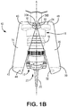
- FIG. 1B is a perspective view of the laser drill with the nozzle cover opened
- FIG. 1C is a perspective view of the nozzle cover in isolation
- FIG. 1D is a top view of the nozzle cover
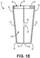
- FIG. 1E is a side cross-sectional view of the nozzle cover.
- Laser drill 10 includes nozzle 12 and nozzle cover 14.
- Nozzle 12 extends along drill axis A and includes neck 16 at top end 18 and tip 20 at bottom end 22.
- Nozzle cover 14 (also called a casing) includes mount 24 with first opening 26, second opening 28, first pivot 30A, second pivot 30B, and pins 32.
- Nozzle cover 14 further includes first shell member 34, second shell member 36, and hollow interior portion 38.
- First shell member 34 includes first end 40, second end 42, first notch 44, and first mating feature 46
- second shell member 36 includes first end 48, second end 50, second notch 52, and second mating feature 54.
- Laser drill 10 produces laser L that extends downward from tip 20 of nozzle 12.
- Laser drill 10 is configured to be used in a variety of applications, including drilling holes in metallic materials and/or alloys.
- Laser drill 10 includes nozzle 12, which extends along drill axis A and is at an end of laser drill 10 from which laser L extends.
- Nozzle 12 is attached to other components of laser drill 10 by neck 16 at top end 18.
- Laser L which is used for drilling, extends downward through tip 20, which is an elongated component at bottom end 22 of nozzle 12.
- Neck 16 and tip 20 can be one continuous and monolithic component, or neck 16 and tip 20 can be multiple pieces fastened together.
- Neck 16 is shown as a substantially cylindrical-shaped portion with a variety of stair-step features, while tip 20 is shown as a frusticonical-shaped elongated portion extending away from neck 16 downward along drill axis A.
- Other embodiments of laser drill 10 can include a nozzle with other configurations suitable to produce and/or focus laser L for drilling.
- Nozzle 12 can have any size and shape because nozzle cover 14 can be sized, shaped, and oriented to accommodate any size and shape of nozzle 12.
- the material removed (i.e., slag) during the drilling by laser L extending out from tip 20 of nozzle 12 can splatter onto laser drill 10 and, in particular, onto nozzle 12.
- nozzle cover 14 is utilized to protect nozzle 12 from the slag to ensure nozzle 12 is not damaged and remains operational.
- Nozzle cover 14 is a protective casing that, when in the closed position, surrounds the entirety of neck 16 and at least a portion of tip 20.
- Mount 24 of nozzle cover 14 attaches nozzle cover 14 to nozzle 12 and/or other components of laser drill 10, while first shell member 34 and second shell member 36 are configured to extend away from mount 24 to surround nozzle 12.
- Nozzle cover 14 can be constructed from any material(s) suitable for protecting nozzle 12 from slag, such as a polymer material to which the slag has difficulty binding to and attaching. Additionally, nozzle cover 14 can be constructed from a material that is opaque, translucent, or transparent (as shown) depending on the material used and the need to see nozzle 12 during operation of laser drill 10.
- nozzle cover 14 can have other configurations suitable for enclosing nozzle 12 when nozzle cover 14 is in the closed position.
- mount 24 includes first opening 26 (centered about drill axis A) and is annular in shape to encircle neck 16 at top end 18 of neck 16.
- Mount 24 can be any size, shape, and/or configuration suitable to attach nozzle cover 14 to laser drill 10 while providing a support structure to which first shell member 34 and second shell member 36 can attach and pivot.
- Mount 24 can be attached to nozzle 12 and/or another component of laser drill 10 by any type of fastener or by another mechanical means. While shown as a circular aperture in the disclosed embodiment, first opening 26 can have any shape necessary to accommodate and attach to nozzle 12. Further, mount 24 can be separable into at least two pieces to allow for installation onto laser drill 10 without the need for nozzle cover 14 to slide onto laser drill 10.
- Mount 24 includes second opening 28 adjacent first opening 26 through which cables and/or other components of laser drill 10 can extend to communicate with nozzle 12 (or for another purpose). While shown as a substantially square aperture in the disclosed embodiment, second opening 28 can have any shape necessary to accommodate the cables and/or other components of laser drill 10.
- Mount 24 also includes first pivot 30A and second pivot 30B, which extend through mount 24 perpendicular to drill axis A.
- First pivot 30A can include attachment points where first shell member 34 attaches to mount 24 and pivots between the open position and the closed position.
- second pivot 30B can include attachment points where second shell member 34 attaches to mount 24 and pivots between the open position and the closed position.
- First pivot 30A and second pivot 30B can be in close proximity to one another or distant from one another depending on the configuration of first shell member 34, second shell member 36, and mount 24. Extending into mount 24 along first pivot 30A can be pins 32, which are configured to secure first shell member 34 to mount 24 while allowing first shell member 34 to pivot.
- pins 32 can extend into mount 24 along second pivot 30B to secure second shell member 36 to mount 24 while allowing second shell member 36 to pivot.
- Pins 32 can be any sized, shaped, and/or oriented fasteners suitable to secure shell members 34 and 36 to mount 24. As shown, the disclosed embodiment includes four pins: two for each of first shell member 34 and second shell member 36.
- First shell member 34 and second shell member 36 (also called first half shell and second half shell, respectively) form the protective covering that encloses nozzle 12 when nozzle cover 14 is in the closed position.
- First shell member 34 and second shell member 36 can be identical to one another except for first mating feature 46 and second mating feature 54, which may have different configurations.
- First shell member 34 and second shell member 36 collectively form a hollow frusticonical shell (as shown in the disclosed embodiment), a hollow cylindrical shell, or another casing configuration that includes hollow interior portion 38 within which nozzle 12 is located when first shell member 34 and second shell member 36 are in the closed position.
- first shell member 34 and second shell member 36 are centered about drill axis A, while in the open position, first shell member 34 and second shell member 36 are pivoted outward about first pivot 30A and second pivot 30B, respectively, such that second end 42 of first shell member 34 is distant from second end 50 of second shell member 36.
- first end 40 of first shell member 34 is attached to mount 24 at first pivot 30A, while first end 48 of second shell member 36 is attached to mount 24 at second pivot 30B. Distant from mount 24 is second end 42 of first shell member 34 and second end 50 of second shell member 36. As shown in FIG. 1B , when in the open position, second end 42 of first shell member 34 is distant from second end 50 of first shell member 36 because both first shell member 34 and second shell member 36 have pivoted away from each other to allow access to nozzle 12 within hollow interior portion 38.
- First shell member 34 includes first notch 44 at second end 42, while second shell member 36 includes second notch 52 at second end 50.
- First notch 44 and second notch 52 are each cut-outs that collectively form an aperture in second end 42 (of first shell member 34) and second end 50 (of second shell member 36) through which tip 20 of nozzle 12 can extend.
- Each of first notch 44 and second notch 52 can be a semicircular shape (to collectively form a circular aperture when nozzle cover 14 is in the closed position) or another shape to provide the aperture through which tip 20 and/or laser L can extend.
- tip 20 of nozzle 12 can extend out of the aperture created by first notch 44 of first shell member 34 and second notch 52 of second shell member 34.
- nozzle 12 and/or nozzle cover 14 can be configured such that the entirety of nozzle 12 is enclosed within hollow interior portion 38 when nozzle cover 14 is in the closed position and only laser L extends out during operation.
- First shell member 34 can include first mating feature 46, while second shell member 36 can include second mating feature 54.
- First mating feature 46 and second mating feature 54 are configured to mate with one another to securely hold second end 42 of first shell member 34 adjacent second end 50 of second shell member 36 so that nozzle cover 14 remains in the closed position while also allowing for disengagement so that first shell member 34 and second shell member 36 can pivot into the open position.
- first mating feature 46 can be a tab with second mating feature 54 being a slot. The tab can be configured to be radially outward from the slot and extend into the slot to press fit and hold the tab adjacent the slot.
- first mating feature 46 and second mating feature 54 can have other configurations suitable to allow for engagement (to securely hold nozzle cover 14 in the closed position) and disengagement (to allow for nozzle cover 14 to pivot into the open position). Additionally, first shell member 34 and second shell member 36 can include multiple mating features, or other embodiments do not need to include mating features.
- nozzle cover 14 can includes more than two shell members 34 and 36 that pivot about mount 24 at additional and/or differently configured pivots between the open and closed position.
- Nozzle cover 14 for laser drill 10 includes mount 24 for attaching nozzle cover 14 to nozzle 12 (and/or other components of laser drill 10).
- Nozzle cover 14 also includes shell members 34 and 36 that form a clamshell-like casing around nozzle 12 to protect nozzle 12 from slag that would otherwise splatter nozzle 12 during operation of laser drill 10.
- Shell members 34 and 36 pivot/rotate about pivots 30A and 30B, respectively, on mount 24 between the closed position in which shell members 34 and 36 surround/enclose nozzle 12 to protect nozzle 12 and the open position in which shell members 34 and 36 are rotated away from one another to expose nozzle 12 and allow access to nozzle 12 for maintenance.
- Nozzle 12 can be configured to have two shell members 34 and 36 (as shown) or more than two shell members that pivot between the open position and the closed position. Further, shell members 34 and 36 can include mating features 46 and 54 that are configured to mate with one another to securely hold shell members 34 and 36 adjacent one another in the closed position while also being disengageable to allow for shell members 34 and 36 to pivot into the open position.
- a nozzle cover for a laser drill includes a mount, a first shell member, and a second shell member.
- the mount has a first opening centered about a drill axis through which a nozzle can extend.
- the first shell member extends along the drill axis and has a first end attached to the mount at a first pivot and a second end with a first notch.
- the second shell member extends along the drill axis and has a first end attached to the mount at a second pivot and a second end with a second notch.
- the first shell member and the second shell member are configured to pivot between a closed position in which the first shell member and the second shell member form a hollow interior portion coaxial with the drill axis to at least partially enclose the nozzle and an open position in which the second end of the first shell member is distant from the second end of the second shell member to expose the nozzle.
- nozzle cover of the preceding paragraph can optionally include, additionally and/or alternatively, any one or more of the following features, configurations, and/or additional components:
- the first notch is semicircular and the second notch is semicircular and adjacent to the first notch when the nozzle cover is in the closed position.
- the first shell member and the second shell member each form half of a hollow cylindrical shell.
- the first shell member and the second shell member each form half of a hollow frusticonical shell.
- the mount is separable into at least two pieces.
- the mount includes a second opening configured to allow cables to extend through the mount adjacent to the nozzle.
- the mount is annular in shape.
- the first shell member includes a first mating feature and the second shell member includes a second mating feature configured to mate with the first mating feature to securely hold the second shell member adjacent the first shell member.
- the first mating feature is a slot and the second mating feature is a tab configured to extend into the slot.
- the first shell member and the second shell member are constructed from a polymer material.
- a laser drill assembly includes the nozzle extending along the drill axis and having a neck at a top to which the mount attaches and a tip at a bottom from which a laser is configured to extend and the nozzle cover disclosed above.
- the tip is elongated and extends along the drill axis through the first notch and the second notch when the nozzle cover is in the closed position.
- a laser drill includes a nozzle and a casing.
- the nozzle has a neck at a top end and a tip at a bottom end from which a laser is configured to extend.
- the casing includes a mount attached to the neck of the nozzle and having a first pivot and a second pivot, a first half shell having a first end attached to the mount at the first pivot and a second end with a first half slot, and a second half shell having a first end attached to the mount at the second pivot and a second end with a second half slot.
- the first half shell is configured to pivot about the first pivot and the second half shell is configured to pivot about the second pivot between a closed position in which the casing surrounds at least a portion of the nozzle and an open position in which the second end of the first half shell and the second end of the second half shell are distant from one another.
- the laser drill of the preceding paragraph can optionally include, additionally and/or alternatively, any one or more of the following features, configurations, and/or additional components:
- the tip of the nozzle extends through the first half slot and second half slot when the casing is in the closed position.
- the first half shell and the second half shell collectively form a hollow frusticonical shape.
- the mount is annular in shape and encircles the top end of the nozzle.
- the mount is separable into at least two pieces.
- the mount includes a passage configured to allow cables of the laser drill to extend through the mount to attach to the neck of the nozzle.
- the first half shell includes a first mating feature and the second half shell includes a second mating feature configured to mate with the first mating feature to securely hold the first half shell adjacent to the second half shell.
Landscapes
- Engineering & Computer Science (AREA)
- Physics & Mathematics (AREA)
- Optics & Photonics (AREA)
- Plasma & Fusion (AREA)
- Mechanical Engineering (AREA)
- Laser Beam Processing (AREA)
- Lasers (AREA)
- Processing Of Stones Or Stones Resemblance Materials (AREA)
Abstract
Description
- The present invention relates to a cover for a nozzle of a drill and, in particular, to a clamshell-like cover for a nozzle of a laser drill.
- When using a laser to melt a material, such as a metallic material and/or alloy, to form holes and other openings, the material removed (called the slag) can splatter back onto the nozzle of the laser. The slag can then cool and solidify on the nozzle. Over time, the slag can build up on the nozzle and either needs to be removed from the nozzle (through chemical or mechanical means) or the nozzle needs to be replaced. Each of these solutions requires time and expense as the laser ceases operation during the repair.
- A nozzle cover for a laser drill includes a mount, a first shell member, and a second shell member. The mount has a first opening centered about a drill axis through which a nozzle can extend. The first shell member extends along the drill axis and has a first end attached to the mount at a first pivot and a second end with a first notch. The second shell member extends along the drill axis and has a first end attached to the mount at a second pivot and a second end with a second notch. The first shell member and the second shell member are configured to pivot between a closed position in which the first shell member and the second shell member form a hollow interior portion coaxial with the drill axis to at least partially enclose the nozzle and an open position in which the second end of the first shell member is distant from the second end of the second shell member to expose the nozzle.
- A laser drill includes a nozzle and a casing. The nozzle has a neck at a top end and a tip at a bottom end from which a laser is configured to extend. The casing includes a mount attached to the neck of the nozzle and having a first pivot and a second pivot, a first half shell having a first end attached to the mount at the first pivot and a second end with a first half slot, and a second half shell having a first end attached to the mount at the second pivot and a second end with a second half slot. The first half shell is configured to pivot about the first pivot and the second half shell is configured to pivot about the second pivot between a closed position in which the casing surrounds at least a portion of the nozzle and an open position in which the second end of the first half shell and the second end of the second half shell are distant from one another.
-
-
FIG. 1A is a perspective view of a laser drill with a nozzle protected by a cover. -
FIG. 1B is a perspective view of the laser drill with the cover opened. -
FIG. 1C is a perspective view of the cover in isolation. -
FIG. 1D is a top view of the cover. -
FIG. 1E is a side cross-sectional view of the cover. - A nozzle cover for a laser drill includes a mount for attaching the nozzle cover to a nozzle of the laser drill and shell members that form a clamshell-like casing around the nozzle to protect the nozzle from slag that otherwise would splatter the nozzle during operation of the laser drill. The shell members rotate about pivot points on the mount between a closed position in which the shell members surround/enclose the nozzle to protect the nozzle and an open position in which the two shell members are rotated away from one another to expose the nozzle and allow access to the nozzle for maintenance. The nozzle can be configured to have two shell members (as shown in the disclosed embodiment) or more than two shell members that pivot between the open position and the closed position. Further, the shell members can include mating features that are configured to mate with one another to securely hold the shell members adjacent one another in the closed position while also being disengageable to allow for the shell members to pivot into the open position.
-
FIG. 1A is a perspective view of a laser drill with a nozzle protected by a nozzle cover,FIG. 1B is a perspective view of the laser drill with the nozzle cover opened,FIG. 1C is a perspective view of the nozzle cover in isolation,FIG. 1D is a top view of the nozzle cover, andFIG. 1E is a side cross-sectional view of the nozzle cover. -
Laser drill 10 includesnozzle 12 andnozzle cover 14.Nozzle 12 extends along drill axis A and includesneck 16 attop end 18 andtip 20 atbottom end 22. Nozzle cover 14 (also called a casing) includesmount 24 with first opening 26, second opening 28,first pivot 30A,second pivot 30B, andpins 32.Nozzle cover 14 further includesfirst shell member 34,second shell member 36, and hollowinterior portion 38.First shell member 34 includesfirst end 40,second end 42,first notch 44, andfirst mating feature 46, andsecond shell member 36 includesfirst end 48,second end 50,second notch 52, andsecond mating feature 54.Laser drill 10 produces laser L that extends downward fromtip 20 ofnozzle 12. -
Laser drill 10 is configured to be used in a variety of applications, including drilling holes in metallic materials and/or alloys.Laser drill 10 includesnozzle 12, which extends along drill axis A and is at an end oflaser drill 10 from which laser L extends.Nozzle 12 is attached to other components oflaser drill 10 byneck 16 attop end 18. Laser L, which is used for drilling, extends downward throughtip 20, which is an elongated component atbottom end 22 ofnozzle 12.Neck 16 andtip 20 can be one continuous and monolithic component, orneck 16 andtip 20 can be multiple pieces fastened together.Neck 16 is shown as a substantially cylindrical-shaped portion with a variety of stair-step features, whiletip 20 is shown as a frusticonical-shaped elongated portion extending away fromneck 16 downward along drill axis A. Other embodiments oflaser drill 10 can include a nozzle with other configurations suitable to produce and/or focus laser L for drilling.Nozzle 12 can have any size and shape becausenozzle cover 14 can be sized, shaped, and oriented to accommodate any size and shape ofnozzle 12. When in operation, the material removed (i.e., slag) during the drilling by laser L extending out fromtip 20 ofnozzle 12 can splatter ontolaser drill 10 and, in particular, ontonozzle 12. Thus,nozzle cover 14 is utilized to protectnozzle 12 from the slag to ensurenozzle 12 is not damaged and remains operational. -
Nozzle cover 14 is a protective casing that, when in the closed position, surrounds the entirety ofneck 16 and at least a portion oftip 20.Mount 24 ofnozzle cover 14 attachesnozzle cover 14 tonozzle 12 and/or other components oflaser drill 10, whilefirst shell member 34 andsecond shell member 36 are configured to extend away frommount 24 to surroundnozzle 12.Nozzle cover 14 can be constructed from any material(s) suitable for protectingnozzle 12 from slag, such as a polymer material to which the slag has difficulty binding to and attaching. Additionally,nozzle cover 14 can be constructed from a material that is opaque, translucent, or transparent (as shown) depending on the material used and the need to seenozzle 12 during operation oflaser drill 10. While shown withfirst shell member 34 andsecond shell member 36 forming a hollow cylindrical shape (e.g., a hollow frusticonical shape),nozzle cover 14 can have other configurations suitable for enclosingnozzle 12 whennozzle cover 14 is in the closed position. - As shown in
FIGS. 1C-1E ,mount 24 includes first opening 26 (centered about drill axis A) and is annular in shape toencircle neck 16 attop end 18 ofneck 16. Mount 24 can be any size, shape, and/or configuration suitable to attachnozzle cover 14 tolaser drill 10 while providing a support structure to whichfirst shell member 34 andsecond shell member 36 can attach and pivot. Mount 24 can be attached tonozzle 12 and/or another component oflaser drill 10 by any type of fastener or by another mechanical means. While shown as a circular aperture in the disclosed embodiment,first opening 26 can have any shape necessary to accommodate and attach tonozzle 12. Further,mount 24 can be separable into at least two pieces to allow for installation ontolaser drill 10 without the need fornozzle cover 14 to slide ontolaser drill 10.Mount 24 includessecond opening 28 adjacentfirst opening 26 through which cables and/or other components oflaser drill 10 can extend to communicate with nozzle 12 (or for another purpose). While shown as a substantially square aperture in the disclosed embodiment,second opening 28 can have any shape necessary to accommodate the cables and/or other components oflaser drill 10. -
Mount 24 also includesfirst pivot 30A andsecond pivot 30B, which extend throughmount 24 perpendicular to drill axis A.First pivot 30A can include attachment points wherefirst shell member 34 attaches to mount 24 and pivots between the open position and the closed position. Similarly,second pivot 30B can include attachment points wheresecond shell member 34 attaches to mount 24 and pivots between the open position and the closed position.First pivot 30A andsecond pivot 30B can be in close proximity to one another or distant from one another depending on the configuration offirst shell member 34,second shell member 36, and mount 24. Extending intomount 24 alongfirst pivot 30A can be pins 32, which are configured to securefirst shell member 34 to mount 24 while allowingfirst shell member 34 to pivot. Further,similar pins 32 can extend intomount 24 alongsecond pivot 30B to securesecond shell member 36 to mount 24 while allowingsecond shell member 36 to pivot.Pins 32 can be any sized, shaped, and/or oriented fasteners suitable to secureshell members first shell member 34 andsecond shell member 36. -
First shell member 34 and second shell member 36 (also called first half shell and second half shell, respectively) form the protective covering that enclosesnozzle 12 when nozzle cover 14 is in the closed position.First shell member 34 andsecond shell member 36 can be identical to one another except forfirst mating feature 46 andsecond mating feature 54, which may have different configurations.First shell member 34 andsecond shell member 36 collectively form a hollow frusticonical shell (as shown in the disclosed embodiment), a hollow cylindrical shell, or another casing configuration that includes hollowinterior portion 38 within whichnozzle 12 is located whenfirst shell member 34 andsecond shell member 36 are in the closed position. In the closed position,first shell member 34 andsecond shell member 36 are centered about drill axis A, while in the open position,first shell member 34 andsecond shell member 36 are pivoted outward aboutfirst pivot 30A andsecond pivot 30B, respectively, such thatsecond end 42 offirst shell member 34 is distant fromsecond end 50 ofsecond shell member 36. - As shown in
FIGS. 1C and 1D ,first end 40 offirst shell member 34 is attached to mount 24 atfirst pivot 30A, whilefirst end 48 ofsecond shell member 36 is attached to mount 24 atsecond pivot 30B. Distant frommount 24 issecond end 42 offirst shell member 34 andsecond end 50 ofsecond shell member 36. As shown inFIG. 1B , when in the open position,second end 42 offirst shell member 34 is distant fromsecond end 50 offirst shell member 36 because bothfirst shell member 34 andsecond shell member 36 have pivoted away from each other to allow access tonozzle 12 within hollowinterior portion 38. -
First shell member 34 includesfirst notch 44 atsecond end 42, whilesecond shell member 36 includessecond notch 52 atsecond end 50.First notch 44 andsecond notch 52 are each cut-outs that collectively form an aperture in second end 42 (of first shell member 34) and second end 50 (of second shell member 36) through whichtip 20 ofnozzle 12 can extend. Each offirst notch 44 andsecond notch 52 can be a semicircular shape (to collectively form a circular aperture when nozzle cover 14 is in the closed position) or another shape to provide the aperture through whichtip 20 and/or laser L can extend. When in the closed position, tip 20 ofnozzle 12 can extend out of the aperture created byfirst notch 44 offirst shell member 34 andsecond notch 52 ofsecond shell member 34. Alternately,nozzle 12 and/ornozzle cover 14 can be configured such that the entirety ofnozzle 12 is enclosed within hollowinterior portion 38 when nozzle cover 14 is in the closed position and only laser L extends out during operation. -
First shell member 34 can includefirst mating feature 46, whilesecond shell member 36 can includesecond mating feature 54.First mating feature 46 andsecond mating feature 54 are configured to mate with one another to securely holdsecond end 42 offirst shell member 34 adjacentsecond end 50 ofsecond shell member 36 so that nozzle cover 14 remains in the closed position while also allowing for disengagement so thatfirst shell member 34 andsecond shell member 36 can pivot into the open position. As shown inFIGS. 1C and1E ,first mating feature 46 can be a tab withsecond mating feature 54 being a slot. The tab can be configured to be radially outward from the slot and extend into the slot to press fit and hold the tab adjacent the slot. While shown as a tab and slot arrangement,first mating feature 46 andsecond mating feature 54 can have other configurations suitable to allow for engagement (to securely holdnozzle cover 14 in the closed position) and disengagement (to allow fornozzle cover 14 to pivot into the open position). Additionally,first shell member 34 andsecond shell member 36 can include multiple mating features, or other embodiments do not need to include mating features. - While shown as only having two
shell members nozzle cover 14 can includes more than twoshell members mount 24 at additional and/or differently configured pivots between the open and closed position. -
Nozzle cover 14 forlaser drill 10 includesmount 24 for attachingnozzle cover 14 to nozzle 12 (and/or other components of laser drill 10).Nozzle cover 14 also includesshell members nozzle 12 to protectnozzle 12 from slag that would otherwise splatternozzle 12 during operation oflaser drill 10.Shell members pivots mount 24 between the closed position in which shellmembers nozzle 12 to protectnozzle 12 and the open position in which shellmembers nozzle 12 and allow access tonozzle 12 for maintenance.Nozzle 12 can be configured to have twoshell members 34 and 36 (as shown) or more than two shell members that pivot between the open position and the closed position. Further,shell members shell members shell members - The following are non-exclusive descriptions of possible embodiments of the present invention.
- A nozzle cover for a laser drill includes a mount, a first shell member, and a second shell member. The mount has a first opening centered about a drill axis through which a nozzle can extend. The first shell member extends along the drill axis and has a first end attached to the mount at a first pivot and a second end with a first notch. The second shell member extends along the drill axis and has a first end attached to the mount at a second pivot and a second end with a second notch. The first shell member and the second shell member are configured to pivot between a closed position in which the first shell member and the second shell member form a hollow interior portion coaxial with the drill axis to at least partially enclose the nozzle and an open position in which the second end of the first shell member is distant from the second end of the second shell member to expose the nozzle.
- The nozzle cover of the preceding paragraph can optionally include, additionally and/or alternatively, any one or more of the following features, configurations, and/or additional components:
- The first notch is semicircular and the second notch is semicircular and adjacent to the first notch when the nozzle cover is in the closed position.
- The first shell member and the second shell member each form half of a hollow cylindrical shell.
- The first shell member and the second shell member each form half of a hollow frusticonical shell.
- The mount is separable into at least two pieces.
- The mount includes a second opening configured to allow cables to extend through the mount adjacent to the nozzle.
- The mount is annular in shape.
- The first shell member includes a first mating feature and the second shell member includes a second mating feature configured to mate with the first mating feature to securely hold the second shell member adjacent the first shell member.
- The first mating feature is a slot and the second mating feature is a tab configured to extend into the slot.
- The first shell member and the second shell member are constructed from a polymer material.
- A laser drill assembly includes the nozzle extending along the drill axis and having a neck at a top to which the mount attaches and a tip at a bottom from which a laser is configured to extend and the nozzle cover disclosed above.
- The tip is elongated and extends along the drill axis through the first notch and the second notch when the nozzle cover is in the closed position.
- A laser drill includes a nozzle and a casing. The nozzle has a neck at a top end and a tip at a bottom end from which a laser is configured to extend. The casing includes a mount attached to the neck of the nozzle and having a first pivot and a second pivot, a first half shell having a first end attached to the mount at the first pivot and a second end with a first half slot, and a second half shell having a first end attached to the mount at the second pivot and a second end with a second half slot. The first half shell is configured to pivot about the first pivot and the second half shell is configured to pivot about the second pivot between a closed position in which the casing surrounds at least a portion of the nozzle and an open position in which the second end of the first half shell and the second end of the second half shell are distant from one another.
- The laser drill of the preceding paragraph can optionally include, additionally and/or alternatively, any one or more of the following features, configurations, and/or additional components:
- The tip of the nozzle extends through the first half slot and second half slot when the casing is in the closed position.
- The first half shell and the second half shell collectively form a hollow frusticonical shape.
- The mount is annular in shape and encircles the top end of the nozzle.
- The mount is separable into at least two pieces.
- The mount includes a passage configured to allow cables of the laser drill to extend through the mount to attach to the neck of the nozzle.
- The first half shell includes a first mating feature and the second half shell includes a second mating feature configured to mate with the first mating feature to securely hold the first half shell adjacent to the second half shell.
- A first pin and a second pin that each extend through the first half shell and into the mount along the first pivot and a third pin and a fourth pin that each extend through the second half shell and into the mount along the second pivot.
- While the invention has been described with reference to an exemplary embodiment(s), it will be understood by those skilled in the art that various changes may be made and equivalents may be substituted for elements thereof without departing from the scope of the invention. In addition, many modifications may be made to adapt a particular situation or material to the teachings of the invention without departing from the essential scope thereof. Therefore, it is intended that the invention not be limited to the particular embodiment(s) disclosed, but that the invention will include all embodiments falling within the scope of the appended claims.
Claims (15)
- A nozzle cover (14) for a laser drill (10), the nozzle cover (14) comprising:a mount (24) with a first opening centered about a drill axis through which a nozzle (12) can extend;a first shell member (34) extending along the drill axis, the first shell member (34) having a first end attached to the mount (24) at a first pivot (30A) and a second end with a first notch; anda second shell member (36) extending along the drill axis, the second shell member (36) having a first end attached to the mount (24) at a second pivot (30B) and a second end with a second notch,wherein the first shell member (34) and the second shell member (36) are configured to pivot between a closed position in which the first shell member (34) and the second shell member (36) form a hollow interior portion coaxial with the drill axis to at least partially enclose the nozzle (12) and an open position in which the second end of the first shell member (34) is distant from the second end of the second shell member (36) to expose the nozzle (12).
- The nozzle cover (14) of claim 1, wherein the first notch is semicircular and the second notch is semicircular and adjacent to the first notch when the nozzle cover (14) is in the closed position.
- The nozzle cover (14) of claim 1 or 2, wherein the first shell member (34) and the second shell member (36) each form half of a hollow cylindrical shell.
- The nozzle cover (14) of any preceding claim, wherein the first shell member (34) and the second shell member (36) each form half of a hollow frusticonical shell.
- The nozzle cover (14) of any preceding claim, wherein the mount (24) is separable into at least two pieces.
- The nozzle cover (14) of any preceding claim, wherein the mount (24) includes a second opening configured to allow cables to extend through the mount (24) adjacent to the nozzle (12).
- The nozzle cover (14) of any preceding claim, wherein the mount (24) is annular in shape and optionally encircles the top end of the nozzle (12).
- The nozzle cover (14) of any preceding claim, wherein the first shell member (34) includes a first mating feature (46) and the second shell member (36) includes a second mating feature (54) configured to mate with the first mating feature (46) to securely hold the second shell member (36) adjacent the first shell member (34).
- The nozzle cover (14) of claim 8, wherein the first mating feature (46) is a slot and the second mating feature (54) is a tab configured to extend into the slot.
- The nozzle cover (14) of any preceding claim, wherein the first shell member (34) and the second shell member (36) are constructed from a polymer material.
- The nozzle cover of any preceding claim, further comprising:a first pin and a second pin that each extend through the first shell member (34) and into the mount (24) along the first pivot (30A); anda third pin and a fourth pin that each extend through the second shell member (36) and into the mount (24) along the second pivot (30B).
- A laser drill assembly comprising the nozzle cover (14) of any preceding claim, further comprising:the nozzle (12) extending along the drill axis and having a neck (16) at a top to which the mount (24) attaches and a tip (20) at a bottom from which a laser is configured to extend.
- The laser drill assembly of claim 12, wherein the tip (20) is elongated and extends along the drill axis through the first notch and the second notch when the nozzle cover (14) is in the closed position.
- A laser drill comprising:a nozzle having a neck at a top end and a tip at a bottom end from which a laser is configured to extend; anda casing comprising:a mount attached to the neck of the nozzle and having a first pivot and a second pivot;a first half shell having a first end attached to the mount at the first pivot and a second end with a first half slot; anda second half shell having a first end attached to the mount at the second pivot and a second end with a second half slot,wherein the first half shell pivots about the first pivot and the second half shell pivots about the second pivot between a closed position in which the casing surrounds at least a portion of the nozzle and an open position in which the second end of the first half shell and the second end of the second half shell are distant from one another.
- The laser drill of claim 14, wherein the mount includes a passage configured to allow cables of the laser drill to extend through the mount to attach to the neck of the nozzle.
Applications Claiming Priority (1)
| Application Number | Priority Date | Filing Date | Title |
|---|---|---|---|
| US15/982,597 US11141816B2 (en) | 2018-05-17 | 2018-05-17 | Nozzle cover |
Publications (2)
| Publication Number | Publication Date |
|---|---|
| EP3587023A1 true EP3587023A1 (en) | 2020-01-01 |
| EP3587023B1 EP3587023B1 (en) | 2022-06-29 |
Family
ID=66589248
Family Applications (1)
| Application Number | Title | Priority Date | Filing Date |
|---|---|---|---|
| EP19174771.6A Active EP3587023B1 (en) | 2018-05-17 | 2019-05-15 | Cover for a laser processing head |
Country Status (2)
| Country | Link |
|---|---|
| US (1) | US11141816B2 (en) |
| EP (1) | EP3587023B1 (en) |
Citations (2)
| Publication number | Priority date | Publication date | Assignee | Title |
|---|---|---|---|---|
| US20130330144A1 (en) * | 2011-03-04 | 2013-12-12 | Kraussmaffei Technologies Gmbh | Device for the extraction, parallel to the process, of processing products arising during the processing of a workpiece |
| CN105364324A (en) * | 2015-11-30 | 2016-03-02 | 苏州市汇峰机械设备有限公司 | Protection device for cutting machine nose |
Family Cites Families (8)
| Publication number | Priority date | Publication date | Assignee | Title |
|---|---|---|---|---|
| EP1652614B1 (en) * | 2004-10-30 | 2009-09-23 | Trumpf Werkzeugmaschinen GmbH + Co. KG | Holding tool for a processing head in a laser processing machine with several anti-colliding elements having means for adjusting the loosening load |
| US8151458B2 (en) | 2008-02-21 | 2012-04-10 | United Technologies Corporation | Non-metallic cover for a fixture |
| US20120085738A1 (en) * | 2009-06-12 | 2012-04-12 | Roger Blaine Trivette | Laser nozzle tip |
| US9427288B1 (en) * | 2013-01-16 | 2016-08-30 | Joseph Chenger | Containment shield for surgical instruments |
| JP2016132032A (en) * | 2015-01-22 | 2016-07-25 | 株式会社デンソー | Hole opening processing device |
| GB201502379D0 (en) | 2015-02-13 | 2015-04-01 | Rolls Royce Plc | An apparatus and a method of machining a shape through a component |
| US10987129B2 (en) * | 2015-09-04 | 2021-04-27 | Medos International Sarl | Multi-shield spinal access system |
| US10335900B2 (en) | 2016-03-03 | 2019-07-02 | General Electric Company | Protective shield for liquid guided laser cutting tools |
-
2018
- 2018-05-17 US US15/982,597 patent/US11141816B2/en active Active
-
2019
- 2019-05-15 EP EP19174771.6A patent/EP3587023B1/en active Active
Patent Citations (2)
| Publication number | Priority date | Publication date | Assignee | Title |
|---|---|---|---|---|
| US20130330144A1 (en) * | 2011-03-04 | 2013-12-12 | Kraussmaffei Technologies Gmbh | Device for the extraction, parallel to the process, of processing products arising during the processing of a workpiece |
| CN105364324A (en) * | 2015-11-30 | 2016-03-02 | 苏州市汇峰机械设备有限公司 | Protection device for cutting machine nose |
Also Published As
| Publication number | Publication date |
|---|---|
| US20190351508A1 (en) | 2019-11-21 |
| US11141816B2 (en) | 2021-10-12 |
| EP3587023B1 (en) | 2022-06-29 |
Similar Documents
| Publication | Publication Date | Title |
|---|---|---|
| US6710249B1 (en) | Wire separator | |
| US20190366562A1 (en) | Cable harness management module and a robot | |
| US10175562B2 (en) | Support and connection unit for cameras | |
| EP3282529B1 (en) | Cable management assembly and cable management device thereof | |
| US11141816B2 (en) | Nozzle cover | |
| KR20170065500A (en) | Protection devices for gamma radiography | |
| US6857884B2 (en) | Cover for jack hole | |
| US11217401B2 (en) | Explosion proof pressure resistant housing | |
| US4937405A (en) | Vacuum switch chamber | |
| WO2001081865A3 (en) | Snap fit magnetic shields for laser gyroscopes | |
| TW201707292A (en) | Protective cover for a connector | |
| KR200481494Y1 (en) | motor overload protective equipment | |
| KR102058849B1 (en) | Clip-type cable holder and cable fixing device including the same | |
| EP2724957B1 (en) | Container closure system | |
| JPH03153908A (en) | Lock mechanism | |
| GB2274931A (en) | Watch case | |
| CN205452220U (en) | Safeties and have this safeties's car | |
| CN109563962B (en) | Protective cover | |
| US3037154A (en) | Enclosure | |
| JP2006081276A (en) | Electric connection box | |
| FR3070340B1 (en) | GLOVE BOX LOCKING MECHANISM | |
| JP6309277B2 (en) | Electrical junction box | |
| US20160099558A1 (en) | Apparatus and method for preventing intrusion into splice closure | |
| CN107968391A (en) | A kind of Surge Protector for realizing quick assembling | |
| EP3200296B1 (en) | Portable power distribution assembly |
Legal Events
| Date | Code | Title | Description |
|---|---|---|---|
| PUAI | Public reference made under article 153(3) epc to a published international application that has entered the european phase |
Free format text: ORIGINAL CODE: 0009012 |
|
| STAA | Information on the status of an ep patent application or granted ep patent |
Free format text: STATUS: THE APPLICATION HAS BEEN PUBLISHED |
|
| AK | Designated contracting states |
Kind code of ref document: A1 Designated state(s): AL AT BE BG CH CY CZ DE DK EE ES FI FR GB GR HR HU IE IS IT LI LT LU LV MC MK MT NL NO PL PT RO RS SE SI SK SM TR |
|
| AX | Request for extension of the european patent |
Extension state: BA ME |
|
| STAA | Information on the status of an ep patent application or granted ep patent |
Free format text: STATUS: REQUEST FOR EXAMINATION WAS MADE |
|
| 17P | Request for examination filed |
Effective date: 20200701 |
|
| RBV | Designated contracting states (corrected) |
Designated state(s): AL AT BE BG CH CY CZ DE DK EE ES FI FR GB GR HR HU IE IS IT LI LT LU LV MC MK MT NL NO PL PT RO RS SE SI SK SM TR |
|
| RAP1 | Party data changed (applicant data changed or rights of an application transferred) |
Owner name: RAYTHEON TECHNOLOGIES CORPORATION |
|
| STAA | Information on the status of an ep patent application or granted ep patent |
Free format text: STATUS: EXAMINATION IS IN PROGRESS |
|
| 17Q | First examination report despatched |
Effective date: 20210329 |
|
| GRAP | Despatch of communication of intention to grant a patent |
Free format text: ORIGINAL CODE: EPIDOSNIGR1 |
|
| STAA | Information on the status of an ep patent application or granted ep patent |
Free format text: STATUS: GRANT OF PATENT IS INTENDED |
|
| INTG | Intention to grant announced |
Effective date: 20211206 |
|
| GRAS | Grant fee paid |
Free format text: ORIGINAL CODE: EPIDOSNIGR3 |
|
| GRAA | (expected) grant |
Free format text: ORIGINAL CODE: 0009210 |
|
| STAA | Information on the status of an ep patent application or granted ep patent |
Free format text: STATUS: THE PATENT HAS BEEN GRANTED |
|
| AK | Designated contracting states |
Kind code of ref document: B1 Designated state(s): AL AT BE BG CH CY CZ DE DK EE ES FI FR GB GR HR HU IE IS IT LI LT LU LV MC MK MT NL NO PL PT RO RS SE SI SK SM TR |
|
| REG | Reference to a national code |
Ref country code: CH Ref legal event code: EP |
|
| REG | Reference to a national code |
Ref country code: DE Ref legal event code: R096 Ref document number: 602019016335 Country of ref document: DE |
|
| REG | Reference to a national code |
Ref country code: AT Ref legal event code: REF Ref document number: 1500997 Country of ref document: AT Kind code of ref document: T Effective date: 20220715 |
|
| REG | Reference to a national code |
Ref country code: IE Ref legal event code: FG4D |
|
| REG | Reference to a national code |
Ref country code: LT Ref legal event code: MG9D |
|
| PG25 | Lapsed in a contracting state [announced via postgrant information from national office to epo] |
Ref country code: SE Free format text: LAPSE BECAUSE OF FAILURE TO SUBMIT A TRANSLATION OF THE DESCRIPTION OR TO PAY THE FEE WITHIN THE PRESCRIBED TIME-LIMIT Effective date: 20220629 Ref country code: NO Free format text: LAPSE BECAUSE OF FAILURE TO SUBMIT A TRANSLATION OF THE DESCRIPTION OR TO PAY THE FEE WITHIN THE PRESCRIBED TIME-LIMIT Effective date: 20220929 Ref country code: LT Free format text: LAPSE BECAUSE OF FAILURE TO SUBMIT A TRANSLATION OF THE DESCRIPTION OR TO PAY THE FEE WITHIN THE PRESCRIBED TIME-LIMIT Effective date: 20220629 Ref country code: HR Free format text: LAPSE BECAUSE OF FAILURE TO SUBMIT A TRANSLATION OF THE DESCRIPTION OR TO PAY THE FEE WITHIN THE PRESCRIBED TIME-LIMIT Effective date: 20220629 Ref country code: GR Free format text: LAPSE BECAUSE OF FAILURE TO SUBMIT A TRANSLATION OF THE DESCRIPTION OR TO PAY THE FEE WITHIN THE PRESCRIBED TIME-LIMIT Effective date: 20220930 Ref country code: FI Free format text: LAPSE BECAUSE OF FAILURE TO SUBMIT A TRANSLATION OF THE DESCRIPTION OR TO PAY THE FEE WITHIN THE PRESCRIBED TIME-LIMIT Effective date: 20220629 Ref country code: BG Free format text: LAPSE BECAUSE OF FAILURE TO SUBMIT A TRANSLATION OF THE DESCRIPTION OR TO PAY THE FEE WITHIN THE PRESCRIBED TIME-LIMIT Effective date: 20220929 |
|
| REG | Reference to a national code |
Ref country code: NL Ref legal event code: MP Effective date: 20220629 |
|
| REG | Reference to a national code |
Ref country code: AT Ref legal event code: MK05 Ref document number: 1500997 Country of ref document: AT Kind code of ref document: T Effective date: 20220629 |
|
| PG25 | Lapsed in a contracting state [announced via postgrant information from national office to epo] |
Ref country code: RS Free format text: LAPSE BECAUSE OF FAILURE TO SUBMIT A TRANSLATION OF THE DESCRIPTION OR TO PAY THE FEE WITHIN THE PRESCRIBED TIME-LIMIT Effective date: 20220629 Ref country code: LV Free format text: LAPSE BECAUSE OF FAILURE TO SUBMIT A TRANSLATION OF THE DESCRIPTION OR TO PAY THE FEE WITHIN THE PRESCRIBED TIME-LIMIT Effective date: 20220629 |
|
| PG25 | Lapsed in a contracting state [announced via postgrant information from national office to epo] |
Ref country code: NL Free format text: LAPSE BECAUSE OF FAILURE TO SUBMIT A TRANSLATION OF THE DESCRIPTION OR TO PAY THE FEE WITHIN THE PRESCRIBED TIME-LIMIT Effective date: 20220629 |
|
| PG25 | Lapsed in a contracting state [announced via postgrant information from national office to epo] |
Ref country code: SM Free format text: LAPSE BECAUSE OF FAILURE TO SUBMIT A TRANSLATION OF THE DESCRIPTION OR TO PAY THE FEE WITHIN THE PRESCRIBED TIME-LIMIT Effective date: 20220629 Ref country code: SK Free format text: LAPSE BECAUSE OF FAILURE TO SUBMIT A TRANSLATION OF THE DESCRIPTION OR TO PAY THE FEE WITHIN THE PRESCRIBED TIME-LIMIT Effective date: 20220629 Ref country code: RO Free format text: LAPSE BECAUSE OF FAILURE TO SUBMIT A TRANSLATION OF THE DESCRIPTION OR TO PAY THE FEE WITHIN THE PRESCRIBED TIME-LIMIT Effective date: 20220629 Ref country code: PT Free format text: LAPSE BECAUSE OF FAILURE TO SUBMIT A TRANSLATION OF THE DESCRIPTION OR TO PAY THE FEE WITHIN THE PRESCRIBED TIME-LIMIT Effective date: 20221031 Ref country code: ES Free format text: LAPSE BECAUSE OF FAILURE TO SUBMIT A TRANSLATION OF THE DESCRIPTION OR TO PAY THE FEE WITHIN THE PRESCRIBED TIME-LIMIT Effective date: 20220629 Ref country code: EE Free format text: LAPSE BECAUSE OF FAILURE TO SUBMIT A TRANSLATION OF THE DESCRIPTION OR TO PAY THE FEE WITHIN THE PRESCRIBED TIME-LIMIT Effective date: 20220629 Ref country code: AT Free format text: LAPSE BECAUSE OF FAILURE TO SUBMIT A TRANSLATION OF THE DESCRIPTION OR TO PAY THE FEE WITHIN THE PRESCRIBED TIME-LIMIT Effective date: 20220629 |
|
| PG25 | Lapsed in a contracting state [announced via postgrant information from national office to epo] |
Ref country code: PL Free format text: LAPSE BECAUSE OF FAILURE TO SUBMIT A TRANSLATION OF THE DESCRIPTION OR TO PAY THE FEE WITHIN THE PRESCRIBED TIME-LIMIT Effective date: 20220629 Ref country code: IS Free format text: LAPSE BECAUSE OF FAILURE TO SUBMIT A TRANSLATION OF THE DESCRIPTION OR TO PAY THE FEE WITHIN THE PRESCRIBED TIME-LIMIT Effective date: 20221029 |
|
| REG | Reference to a national code |
Ref country code: DE Ref legal event code: R097 Ref document number: 602019016335 Country of ref document: DE |
|
| PG25 | Lapsed in a contracting state [announced via postgrant information from national office to epo] |
Ref country code: AL Free format text: LAPSE BECAUSE OF FAILURE TO SUBMIT A TRANSLATION OF THE DESCRIPTION OR TO PAY THE FEE WITHIN THE PRESCRIBED TIME-LIMIT Effective date: 20220629 |
|
| PG25 | Lapsed in a contracting state [announced via postgrant information from national office to epo] |
Ref country code: DK Free format text: LAPSE BECAUSE OF FAILURE TO SUBMIT A TRANSLATION OF THE DESCRIPTION OR TO PAY THE FEE WITHIN THE PRESCRIBED TIME-LIMIT Effective date: 20220629 Ref country code: CZ Free format text: LAPSE BECAUSE OF FAILURE TO SUBMIT A TRANSLATION OF THE DESCRIPTION OR TO PAY THE FEE WITHIN THE PRESCRIBED TIME-LIMIT Effective date: 20220629 |
|
| PLBE | No opposition filed within time limit |
Free format text: ORIGINAL CODE: 0009261 |
|
| STAA | Information on the status of an ep patent application or granted ep patent |
Free format text: STATUS: NO OPPOSITION FILED WITHIN TIME LIMIT |
|
| 26N | No opposition filed |
Effective date: 20230330 |
|
| P01 | Opt-out of the competence of the unified patent court (upc) registered |
Effective date: 20230521 |
|
| PG25 | Lapsed in a contracting state [announced via postgrant information from national office to epo] |
Ref country code: SI Free format text: LAPSE BECAUSE OF FAILURE TO SUBMIT A TRANSLATION OF THE DESCRIPTION OR TO PAY THE FEE WITHIN THE PRESCRIBED TIME-LIMIT Effective date: 20220629 |
|
| REG | Reference to a national code |
Ref country code: CH Ref legal event code: PL |
|
| PG25 | Lapsed in a contracting state [announced via postgrant information from national office to epo] |
Ref country code: MC Free format text: LAPSE BECAUSE OF FAILURE TO SUBMIT A TRANSLATION OF THE DESCRIPTION OR TO PAY THE FEE WITHIN THE PRESCRIBED TIME-LIMIT Effective date: 20220629 |
|
| REG | Reference to a national code |
Ref country code: BE Ref legal event code: MM Effective date: 20230531 |
|
| PG25 | Lapsed in a contracting state [announced via postgrant information from national office to epo] |
Ref country code: MC Free format text: LAPSE BECAUSE OF FAILURE TO SUBMIT A TRANSLATION OF THE DESCRIPTION OR TO PAY THE FEE WITHIN THE PRESCRIBED TIME-LIMIT Effective date: 20220629 Ref country code: LU Free format text: LAPSE BECAUSE OF NON-PAYMENT OF DUE FEES Effective date: 20230515 Ref country code: LI Free format text: LAPSE BECAUSE OF NON-PAYMENT OF DUE FEES Effective date: 20230531 Ref country code: IT Free format text: LAPSE BECAUSE OF FAILURE TO SUBMIT A TRANSLATION OF THE DESCRIPTION OR TO PAY THE FEE WITHIN THE PRESCRIBED TIME-LIMIT Effective date: 20220629 Ref country code: CH Free format text: LAPSE BECAUSE OF NON-PAYMENT OF DUE FEES Effective date: 20230531 |
|
| REG | Reference to a national code |
Ref country code: IE Ref legal event code: MM4A |
|
| PG25 | Lapsed in a contracting state [announced via postgrant information from national office to epo] |
Ref country code: IE Free format text: LAPSE BECAUSE OF NON-PAYMENT OF DUE FEES Effective date: 20230515 |
|
| PG25 | Lapsed in a contracting state [announced via postgrant information from national office to epo] |
Ref country code: IE Free format text: LAPSE BECAUSE OF NON-PAYMENT OF DUE FEES Effective date: 20230515 |
|
| PG25 | Lapsed in a contracting state [announced via postgrant information from national office to epo] |
Ref country code: BE Free format text: LAPSE BECAUSE OF NON-PAYMENT OF DUE FEES Effective date: 20230531 |
|
| PG25 | Lapsed in a contracting state [announced via postgrant information from national office to epo] |
Ref country code: BG Free format text: LAPSE BECAUSE OF FAILURE TO SUBMIT A TRANSLATION OF THE DESCRIPTION OR TO PAY THE FEE WITHIN THE PRESCRIBED TIME-LIMIT Effective date: 20220629 |
|
| PG25 | Lapsed in a contracting state [announced via postgrant information from national office to epo] |
Ref country code: BG Free format text: LAPSE BECAUSE OF FAILURE TO SUBMIT A TRANSLATION OF THE DESCRIPTION OR TO PAY THE FEE WITHIN THE PRESCRIBED TIME-LIMIT Effective date: 20220629 |
|
| PGFP | Annual fee paid to national office [announced via postgrant information from national office to epo] |
Ref country code: DE Payment date: 20250423 Year of fee payment: 7 |
|
| PGFP | Annual fee paid to national office [announced via postgrant information from national office to epo] |
Ref country code: GB Payment date: 20250423 Year of fee payment: 7 |
|
| PGFP | Annual fee paid to national office [announced via postgrant information from national office to epo] |
Ref country code: FR Payment date: 20250423 Year of fee payment: 7 |
|
| PG25 | Lapsed in a contracting state [announced via postgrant information from national office to epo] |
Ref country code: CY Free format text: LAPSE BECAUSE OF FAILURE TO SUBMIT A TRANSLATION OF THE DESCRIPTION OR TO PAY THE FEE WITHIN THE PRESCRIBED TIME-LIMIT; INVALID AB INITIO Effective date: 20190515 |
|
| PG25 | Lapsed in a contracting state [announced via postgrant information from national office to epo] |
Ref country code: HU Free format text: LAPSE BECAUSE OF FAILURE TO SUBMIT A TRANSLATION OF THE DESCRIPTION OR TO PAY THE FEE WITHIN THE PRESCRIBED TIME-LIMIT; INVALID AB INITIO Effective date: 20190515 |
|
| REG | Reference to a national code |
Ref country code: DE Ref legal event code: R081 Ref document number: 602019016335 Country of ref document: DE Owner name: RTX CORPORATION (N.D.GES.D. STAATES DELAWARE),, US Free format text: FORMER OWNER: RAYTHEON TECHNOLOGIES CORPORATION, FARMINGTON, CT, US |
|
| PG25 | Lapsed in a contracting state [announced via postgrant information from national office to epo] |
Ref country code: TR Free format text: LAPSE BECAUSE OF FAILURE TO SUBMIT A TRANSLATION OF THE DESCRIPTION OR TO PAY THE FEE WITHIN THE PRESCRIBED TIME-LIMIT Effective date: 20220629 |