EP3587014A1 - Hard tip band-saw blade - Google Patents
Hard tip band-saw blade Download PDFInfo
- Publication number
- EP3587014A1 EP3587014A1 EP18756795.3A EP18756795A EP3587014A1 EP 3587014 A1 EP3587014 A1 EP 3587014A1 EP 18756795 A EP18756795 A EP 18756795A EP 3587014 A1 EP3587014 A1 EP 3587014A1
- Authority
- EP
- European Patent Office
- Prior art keywords
- tooth
- hard tip
- sawtooth
- saw blade
- following
- Prior art date
- Legal status (The legal status is an assumption and is not a legal conclusion. Google has not performed a legal analysis and makes no representation as to the accuracy of the status listed.)
- Granted
Links
Images





Classifications
-
- B—PERFORMING OPERATIONS; TRANSPORTING
- B23—MACHINE TOOLS; METAL-WORKING NOT OTHERWISE PROVIDED FOR
- B23D—PLANING; SLOTTING; SHEARING; BROACHING; SAWING; FILING; SCRAPING; LIKE OPERATIONS FOR WORKING METAL BY REMOVING MATERIAL, NOT OTHERWISE PROVIDED FOR
- B23D61/00—Tools for sawing machines or sawing devices; Clamping devices for these tools
- B23D61/12—Straight saw blades; Strap saw blades
- B23D61/121—Types of set; Variable teeth, e.g. variable in height or gullet depth; Varying pitch; Details of gullet
- B23D61/1216—Repeating pattern of groups having three or more teeth
-
- B—PERFORMING OPERATIONS; TRANSPORTING
- B23—MACHINE TOOLS; METAL-WORKING NOT OTHERWISE PROVIDED FOR
- B23D—PLANING; SLOTTING; SHEARING; BROACHING; SAWING; FILING; SCRAPING; LIKE OPERATIONS FOR WORKING METAL BY REMOVING MATERIAL, NOT OTHERWISE PROVIDED FOR
- B23D61/00—Tools for sawing machines or sawing devices; Clamping devices for these tools
- B23D61/12—Straight saw blades; Strap saw blades
- B23D61/127—Straight saw blades; Strap saw blades of special material
-
- B—PERFORMING OPERATIONS; TRANSPORTING
- B23—MACHINE TOOLS; METAL-WORKING NOT OTHERWISE PROVIDED FOR
- B23D—PLANING; SLOTTING; SHEARING; BROACHING; SAWING; FILING; SCRAPING; LIKE OPERATIONS FOR WORKING METAL BY REMOVING MATERIAL, NOT OTHERWISE PROVIDED FOR
- B23D61/00—Tools for sawing machines or sawing devices; Clamping devices for these tools
- B23D61/12—Straight saw blades; Strap saw blades
- B23D61/14—Straight saw blades; Strap saw blades with inserted saw teeth, i.e. the teeth being individually inserted
Definitions
- the present invention relates to a hard tip band-saw blade used when a band saw carries out a sawing process (cutting process) on a workpiece (metal work) and having a hard tip made of hard material on the tooth top side of each sawtooth.
- the hard tip band-saw blade has, on the tooth top side of each sawtooth (cutting tooth), a hard tip made of hard material such as cemented carbide .
- Typical hard tip band-saw blades that can be mentioned are the following two type of hard tip band-saw blades.
- a first prior-art hard tip band-saw blade includes alternating sawtooth groups each being a combination of a plurality of sawteeth.
- the plurality of sawteeth in each sawtooth group include a leading tooth and a following tooth.
- the leading tooth is formed in a left-right symmetrical shape.
- a chamfer corner chamfer
- the leading tooth is a bevel tooth that is one of left-right symmetrical sawteeth.
- the following tooth is arranged to follow the leading tooth.
- the tooth height size thereof is set to be smaller than the tooth height size of the leading tooth.
- the following tooth is formed in a left-right symmetrical shape that widens toward a tooth top edge (tooth top ridge line) side like a plectrum (trapezoid or dovetail (dove tail shape)).
- the following tooth is a plectrum tooth (trapezoidal tooth or dovetailed tooth (dove tail shaped tooth)) that is one of the left-right symmetrical sawteeth (refer to Comparison Example 1 to be explained later).
- each tooth top corner part of the hard tip of the following tooth most outwardly protrudes in a left-right direction.
- the following tooth is a finishing tooth to finish a cut face of a workpiece.
- the second prior-art hard tip band-saw blade includes alternating sawtooth groups each being a combination of a plurality of sawteeth.
- the plurality of sawteeth in each sawtooth group include a leading tooth, a first following tooth, and a second following tooth.
- the leading tooth is formed in a left-right symmetrical shape. At a tooth top corner part on each of the left and right sides of a hard tip of the leading tooth, a chamfer is formed.
- the leading tooth is a bevel tooth that is one of the left-right symmetrical sawteeth.
- the first following tooth is arranged to follow the leading tooth.
- the tooth height size thereof is set to be smaller than the tooth height size of the leading tooth.
- the first following tooth is formed like a plectrum (trapezoid or dovetail (dove tail shape)) that widens toward a tooth top edge side. At a tooth top corner part on a left/right first side of a hard tip thereof, a chamfer is formed.
- the first following tooth is a one-side plectrum tooth (set tooth or one-side dovetailed tooth) that is one of left-right asymmetrical sawteeth.
- the second following tooth is arranged to follow the first following tooth.
- the tooth height size thereof is set to be the same as the tooth height size of the first following tooth.
- the second following tooth is formed like a plectrum (trapezoid or dovetail) that widens toward a tooth top edge side. At a tooth top corner part on a left/right second side of a heart tip thereof, a chamfer is formed.
- the second following tooth is a one-side plectrum tooth (set tooth or one-side dovetailed tooth) that is one of the left-right asymmetrical sawteeth (refer to Comparison Example 2 to be explained later).
- a tooth top corner part on a left/right second side of the hard tip of the first following tooth and a tooth top corner part on a left/right first side of the hard tip of the second following tooth most outwardly protrude in the left-right direction.
- the first following tooth and second following tooth are finishing teeth to finish a cut face of a workpiece.
- Patent Literatures 1 to 3 related arts concerning the hard tip band-saw blades are shown in Patent Literatures 1 to 3.
- the hard tip of the following tooth is in a state of being restricted in the left-right direction by a cut groove of the workpiece.
- the crooked cut in a workpiece is a phenomenon caused by a bend of the hard tip band-saw blade depending on material of the workpiece or the worn state, feed rate, cutting rate, and the like of the hard tip band-saw blade, to make a cut face of the workpiece spherical or slanted.
- the crooked cut of a workpiece results in providing an unacceptable product due to an inferior cut face accuracy of the workpiece or damaging the hard tip band-saw blade.
- a hard tip band-saw blade used when carrying out a cutting process on a workpiece that is mainly made of soft metal such as aluminum alloy (hereinafter referred to as a soft metal cutting hard tip band-saw blade, if necessary) has a reduced number of finishing teeth in each sawtooth group.
- the soft metal cutting hard tip band-saw blade more depends on the hardness (softness) and material of a workpiece than the cutting amount (work amount) borne by a single sawtooth. Namely, the soft metal cutting hard tip band-saw blade is inappropriate to cut a workpiece made of hard metal such as steel.
- the present invention has been made in consideration of the above-mentioned circumstances and an object thereof is to provide a hard tip band-saw blade having novel configuration capable of solving the above-mentioned problems.
- the hard tip band-saw blade used when carrying out a sawing process (cutting process) on a workpiece includes alternating sawtooth groups each being a combination of a plurality of sawteeth (cutting teeth) with each sawtooth being provided with a hard tip of hard material on a tooth top side of the sawtooth, wherein each sawtooth group is formed from two sawtooth subgroups, the first sawtooth subgroup has a plurality of sawteeth that include a first leading tooth (first bevel tooth) formed in a left-right symmetrical shape and having a chamfer (corner chamfer) at a tooth top corner part on each of left and right sides of the hard tip and a first following tooth (plectrum tooth or dovetailed tooth (dove tail shaped tooth)) arranged to follow the first leading tooth, set to be smaller than the first leading tooth in tooth height size, and formed in a left-right symmetrical shape that widens toward a tooth top edge
- the first sawtooth subgroup includes the first leading tooth and first following tooth of the above-mentioned configurations and corresponds to the sawtooth group of the first prior-art hard tip band-saw blade.
- the second sawtooth subgroup includes the second leading tooth, second following tooth, and third following tooth of the above-mentioned configurations and corresponds to the sawtooth group of the second prior-art hard tip band-saw blade.
- the hard tip of the first leading tooth, the hard tip of the first following tooth, and the hard tip of the second leading tooth each have a left-right symmetrical shape.
- the third following tooth elastically deforms in a left/right first side direction
- the tooth top corner part on the left/right first side of the hard tip of the third following tooth receives cutting resistance in the left/right direction
- the second following tooth elastically deforms in a left/right second direction.
- the first sawtooth subgroup includes a first middle tooth (first middle bevel tooth) arranged in the middle between the first leading tooth and the first following tooth, set to be smaller than the first leading tooth and larger than the first following tooth in tooth height size, formed in a left-right symmetrical shape, and having a chamfer at a tooth top corner part on each of left and right sides of the hard tip and the second sawtooth subgroup includes a second middle tooth (second middle bevel tooth) arranged in the middle between the second leading tooth and the second following tooth, set to be the same as the first middle tooth in tooth height size, formed in a left-right symmetrical shape, and having a chamfer at a tooth top corner part on each of left and right sides of the hard tip.
- first middle tooth first middle bevel tooth
- the first middle tooth and second middle tooth each have a left-right symmetrical shape. This improves the ratio of the number of left-right symmetrical sawteeth to the total number of sawteeth in each sawtooth group, thereby improving straight motion of the hard tip band-saw blade.
- first middle tooth and second middle tooth are bevel teeth, and therefore, a cutting amount (work amount) by the bevel teeth can be distributed among them in a cut groove depth direction of a workpiece.
- the "left-right” direction is, in a state that the cutting edge (tooth top) of a hard tip band-saw blade is oriented downward, a left-right direction seen from a saw blade forwarding direction (a direction to move forward the hard tip band-saw blade).
- the "left/right first side” is any one of left and right sides.
- the “left/right second side” is an opposite side of the left/right first side. If the left/right first side is the right side, the left/right second side is the left side, and if the left/right first side is the left side, the left/right second side is the right side.
- the "leading” means ahead when seen from the saw blade forwarding direction and the “following” means hind when seen from the saw blade forwarding direction.
- the "saw blade center line” is a line passing through a left-right directional center of the hard tip band-saw blade.
- the "tooth height size” is a dimension from a virtual reference line (not shown in the drawings) extending along a saw back in a body of the hard tip band-saw blade to a tooth top, where the larger the tooth height size, the longer the distance from the saw back to the tooth top and the smaller the tooth height size, the shorter the distance from the saw back to the saw top.
- “L” indicates the left direction
- "R” the right direction
- “F” the saw blade forwarding direction.
- a hard tip band-saw blade 10 is a cutting tool used when carrying out a sawing process (cutting process) by a band saw on a workpiece (metal work) made of hard metal such as steel.
- the hard tip band-saw blade 10 is endlessly structured and a body (main body) of the hard tip band-saw blade 10 is made of alloy steel of high toughness.
- the hard tip band-saw blade 10 has alternating sawtooth groups 12 each being a combination (sawtooth pattern) of a plurality of sawteeth (cutting teeth).
- Each of the sawtooth groups 12 includes two sawtooth subgroups 14 and 16 each being a combination of a plurality of sawteeth.
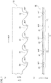
- the first sawtooth subgroup 14 contains a plurality of sawteeth including a first leading tooth 18 and a first following tooth 20.
- the second sawtooth subgroup 16 contains a plurality of sawteeth including a second leading tooth 22, a second following tooth 24, and a third following tooth 26.
- each of the sawtooth groups 12 contains five sawteeth.
- the first leading tooth 18 has, on its tooth top side, a hard tip 18T made of cemented carbide (hard material called cemented carbide containing, for example, tungsten carbide or cobalt).
- the first following tooth 20 has, on its tooth top side, a hard tip 20T made of cemented carbide
- the second leading tooth 22 has, on its tooth top side, a hard tip 22T made of cemented carbide
- the second following tooth 24 has, on its tooth top side, a hard tip 24T made of cemented carbide.
- the third following tooth 26 has, on its tooth top side, a hard tip 26T made of cemented carbide.
- the cemented carbide may additionally contain titanium carbide and the like.
- other hard material such as cermet containing tungsten carbide and the like may be used to form the hard tip 18T and the like.
- the first leading tooth 18 is, as mentioned above, one of the sawteeth that form the first sawtooth subgroup 14 and is a sawtooth to form a cut groove G of a groove width S in the workpiece W. Further, the first leading tooth 18 (the hard tip 18T of the first leading tooth 18) is formed in a left-right symmetrical shape with respect to a saw blade center line M. At a tooth top corner part on each of left and right sides of the hard tip 18T of the first leading tooth 18, a chamfer (corner chamfer) 18Tc is formed.
- the first leading tooth 18 is a first bevel tooth that is one of left-right symmetrical sawteeth.
- a chamfer angle ⁇ 1 of the chamfer 18Tc of the hard tip 18T of the first leading tooth 18 with respect to a tooth top edge (tooth top ridge line) 18Tt is set to, as an example, 40 to 50 degrees.
- the first following tooth 20 is, as mentioned above, one of the sawteeth that constitute the first sawtooth subgroup 14 and is arranged to follow the first leading tooth 18.
- the first following tooth 20 is a sawtooth to expand the cutting groove G of the workpiece W to a groove width P.
- the tooth height size of the first following tooth 20 is set to be smaller than the tooth height size of the first leading tooth 18.
- the first following tooth 20 (the hard tip 20T of the first following tooth 20) is formed like a plectrum (trapezoid or dovetail (dove tail shape)) enlarging toward a tooth top edge 20Tt and is formed in a left-right symmetrical shape with respect to the saw blade center line M.
- a plectrum trapezoid or dovetail (dove tail shape)
- the first following tooth 20 is a plectrum tooth or a dovetailed tooth (dove tail shaped tooth) that is one of the left-right symmetrical sawteeth.
- Each tooth top corner part of the hard tip 20T of the first following tooth 20 is a protruding part (protruding edge part) B that outwardly protrudes in the left-right direction with respect to the chamfer 18Tc of the hard tip 18T of the first leading tooth 18.
- the second leading tooth 22 is, as mentioned above, one of the sawteeth that constitute the second sawtooth subgroup 16 and is a sawtooth to form the cut groove G of the groove width S in the workpiece W.
- the tooth height size of the second leading tooth 22 is set to be the same as the tooth height size of the first leading tooth 18. Further, the second leading tooth 22 (the hard tip 22T of the second leading tooth 22) is formed in a left-right symmetrical shape with respect to the saw blade center line M.
- a chamfer (corner chamfer) 22Tc is formed.
- the second leading tooth 22 is a second bevel tooth that is one of the left-right symmetrical sawteeth.
- a chamfer angle ⁇ 2 of the chamfer 22Tc of the hard tip 22T of the second leading tooth 22 with respect to a tooth top edge 22Tt is set to be equal to the chamfer angle ⁇ 1 of the chamfer 18Tc of the hard tip 18T of the first leading tooth 18 with respect to the tooth top edge (tooth top ridge line) 18Tt.
- the hard tip 22T of the second leading tooth 22 is formed in the same shape as the hard tip 18T of the first leading tooth 18.
- the second following tooth 24 is, as mentioned above, one of the sawteeth that constitute the second sawtooth subgroup 16 and is arranged to follow the second leading tooth 22.
- the second following tooth 24 is a sawtooth that cooperates with the third following tooth 26 to expand the cut groove G to the groove width P.
- the tooth height size of the second following tooth 24 is set to be the same as the tooth height size of the first following tooth 20.
- the second following tooth 24 (the hard tip 24T of the second following tooth 24) is formed like a plectrum that widens toward a tooth top edge 24Tt.
- a chamfer (corner chamfer) 24Tc is formed.
- the second following tooth 24 is a one-side plectrum tooth (set tooth or one-side dovetailed tooth) that is one of left-right asymmetrical sawteeth.
- a chamfer angle ⁇ 3 of the chamfer 24Tc of the second following tooth 24 with respect to the tooth top edge 24Tt is set to be smaller than the chamfer angle ⁇ 2 of the second leading tooth 22 and is set to, as an example, 20 to 40 degrees.
- a tooth top corner part on the left side of the hard tip 24T of the second following tooth 24 is a protruding part B that outwardly protrudes in the left-right direction with respect to the chamfer 22Tc of the hard tip 22T of the second leading tooth 22.
- the third following tooth 26 is, as mentioned above, one of the sawteeth that constitute the second sawtooth subgroup 16 and is arranged to follow the second following tooth 24.
- the third following tooth 26 is a sawtooth that cooperates with the second following tooth 24 to expand the cut groove G of the workpiece W to the groove width P.
- the tooth height size of the third following tooth 26 is set to be the same as the tooth height size of the first following tooth 20.
- the third following tooth 26 (the hard tip 26T of the third following tooth 26) is formed like a plectrum that widens toward a tooth top edge 26Tt.
- a chamfer (corner chamfer) 26Tc is formed at a tooth top corner part on the left side of the hard tip 26T of the third following tooth 26, a chamfer (corner chamfer) 26Tc is formed.
- the third following tooth 26 is a one-side plectrum tooth (set tooth or one-side dovetailed tooth) that is one of the left-right asymmetrical
- a chamfer angle ⁇ 4 of the chamfer 26Tc of the hard tip 26T of the third following tooth 26 with respect to the tooth top edge 26Tt is set to be the same as the chamfer angle ⁇ 3 of the chamfer 24Tc of the hard tip 24T of the second following tooth 24 with respect to the tooth top edge 24Tt.
- a tooth top corner part on the right side of the hard tip 26T of the third following tooth 26 is a protruding part B that outwardly protrudes in the left-right direction with respect to the chamfer 22Tc of the hard tip 22T of the second leading tooth 22.
- a chamfer (not shown) may be formed at the tooth top corner part on the left side of the hard tip 24T of the second following tooth 24.
- a chamfer (not shown) is formed at the tooth top corner part on the right side of the hard tip 26T of the third following tooth 26.
- Each tooth top corner part of the hard tip 20T of the first following tooth 20, the tooth top corner part on the left side of the hard tip 24T of the second following tooth 24, and the tooth top corner part on the right side of the hard tip 26T of the third following tooth 26 each most outwardly protrude in the left-right direction.
- outer ends 20Te in the left-right direction of the tooth top edge (tooth top ridge line) 20Tt of the hard tip 20T of the first following tooth 20, an outer end (left end) 24Te in the left-right direction of the tooth top edge 24Tt of the hard tip 24T of the second following tooth 24, and an outer end (right end) 26Te in the left-right direction of the tooth top edge 26Tt of the hard tip 26T of the third following tooth 26 each are positioned most outwardly in the left-right direction.
- the first following tooth 20, second following tooth 24, and third following tooth 26 are finishing teeth to finish a cut face of the workpiece W.
- the hard tips of the sawteeth that cut a center part (part corresponding to the groove width S) in a groove width direction of the cut groove G of the workpiece W are the hard tip 18T of the first leading tooth 18 and the hard tip 22T of the second leading tooth 22.
- the hard tips of the sawteeth that cut a left end part (part corresponding to a groove width of (P - S) / 2 on the left side) in the groove width direction of the cut groove G of the workpiece W are the hard tip 20T of the first following tooth 20 and the hard tip 24T of the second following tooth 24.
- each of the sawtooth groups 12 includes the same number of and a plurality of (two) sawteeth to cut the respective groove width sections of the cut groove G of the workpiece W.
- the hard tip band-saw blade 10 When the band saw is driven, the hard tip band-saw blade 10 cyclically runs in the saw blade forwarding direction, and at the same time, the hard tip band-saw blade 10 moves in a cutting direction (a direction to approach the workpiece W). Then, in a cutting area of the workpiece W by the band saw, the first leading tooth 18 forms the cut groove G of the groove width S in the workpiece W and the first following tooth 20 widens the cut groove G of the workpiece W to the groove width P. Also, in the cutting area of the workpiece W by the band saw, the second leading tooth 22 forms the cut groove G of the groove width S and the second following tooth 24 and third following tooth 26 widen the cut groove G of the workpiece W to the groove width P.
- the actions mentioned above are continuously carried out so that the first following tooth 20, second following tooth 24, and third following tooth 26 finish a cut face of the workpiece W.
- the hard tip band-saw blade 10 is able to carry out a required sawing process (cutting process) on the workpiece W.
- the first sawtooth subgroup 14 includes the first leading tooth 18 and first following tooth 20 of the above-mentioned configurations and corresponds to the sawtooth group of the first prior-art hard tip band-saw blade.
- the second sawtooth subgroup 16 includes the second leading tooth 22, second following tooth 24, and third following tooth 26 of the above-mentioned configurations and corresponds to the sawtooth group of the second prior-art hard tip band-saw blade.
- the first leading tooth 18, first following tooth 20, and second leading tooth 22 each are left-right symmetrical sawteeth. This heightens the ratio of the number of left-right symmetrical sawteeth to the total number of sawteeth in each sawtooth group 12.
- the second following tooth 24 and the body (the body of the hard tip band-saw blade 10) elastically deforms in the right direction.
- the tooth top corner part on the right side of the hard tip 26T of the third following tooth 26 receives left-right directional cutting resistance
- the third following tooth 26 and the body elastically deforms in the left direction.
- the second following tooth 24, third following tooth 26, and body elastically deform while keeping a balanced state in the left-right direction.
- the left-right directional elastic deformations of the second following tooth 24, third following tooth 26, and body absorb the manufacturing errors, thereby keeping straight movement of the hard tip band-saw blade 10. In addition, it sufficiently prevents the tooth breakage of the second following tooth 24 and third following tooth 26.
- each of the sawtooth groups 12 has the same number of and a plurality of sawteeth to cut the respective sections in the groove width direction of the cut groove G in the workpiece W. This results in distributing cutting resistance acting on the sawteeth over the sawteeth in each sawtooth group 12 and equalizing work amount of the sawteeth in each sawtooth group 12.
- the first embodiment is able to sufficiently suppress a crooked cut or the like by the hard tip band-saw blade 10 and improve the cut face accuracy of a workpiece W and the service life of the hard tip band-saw blade 10.
- it is able to distribute cutting resistance among the sawteeth in each of the sawtooth groups 12 and substantially equalize work amount of the sawteeth in each sawtooth group 12, thereby further improving the service life of the hard tip band-saw blade 10.
- a hard tip band-saw blade 28 according to the second embodiment has a configuration similar to that of the hard tip band-saw blade 10 according to the first embodiment (refer to Fig. 1(a)(b) ).
- a hard tip band-saw blade 28 in the configuration of the hard tip band-saw blade 28, only part differing from the hard tip band-saw blade 10 will be explained.
- those corresponding to the structural elements of the hard tip band-saw blade 10 are represented with the same reference marks in the drawings.
- the hard tip band-saw blade 28 has alternating sawtooth groups 30 each being a combination (sawtooth pattern) of a plurality of sawteeth (cutting teeth).
- Each of the sawtooth groups 30 includes two sawtooth subgroups 32 and 34 each being a combination of a plurality of sawteeth.
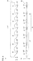
- the first sawtooth subgroup 32 includes as the plurality of sawteeth, unlike the first sawtooth subgroup 14 of the hard tip band-saw blade 10 (refer to Fig. 1(a),(b) ), a first leading tooth 18 and a first following tooth 20, and in addition, a first middle tooth 36.
- the second sawtooth subgroup 34 includes as the plurality of sawteeth, unlike the second sawtooth subgroup 16 of the hard tip band-saw blade 10 (refer to Fig. 1(a)(b) ), a second leading tooth 22, a second following tooth 24, and a third following tooth 26, and in addition, a second middle tooth 38.
- each of the sawtooth groups 30 includes seven sawteeth.
- the first middle tooth 36 has, on its tooth top side, a hard tip 36T made of cemented carbide (hard material called cemented carbide containing, for example, tungsten carbide or cobalt) .
- the second middle tooth 38 has, on its tooth top side, a hard tip 38T made of cemented carbide.
- the cemented carbide may additionally contain titanium carbide or the like.
- other hard material such as cermet containing tungsten carbide or the like may be employed as a material to form the hard tip 36T and the like.
- the first middle tooth 36 is, as mentioned above, one of the sawteeth that form the first sawtooth subgroup 32 and is arranged between the first leading tooth 18 and the first following tooth 20.
- the first middle tooth 36 is a sawtooth to widen a cut groove G in a workpiece W to a groove width K.
- the tooth height size of the first middle tooth 36 is set to be smaller than the tooth height size of the first leading tooth 18 and larger than the tooth height size of the first following tooth 20.
- the first middle tooth 36 (the hard tip 36T of the first middle tooth 36) is formed in a left-right symmetrical shape with respect to a saw blade center line M.
- a chamfer (corner chamfer) 36Tc is formed.
- the first middle tooth 36 is a first middle bevel tooth that is one of left-right symmetrical sawteeth.
- a chamfer angle ⁇ 5 of the chamfer 36Tc of the hard tip 36T of the first middle tooth 36 with respect to a tooth top edge (tooth top ridge line) 36Tt is set to be the same as that of the chamfer 18Tc of the hard tip 18T of the first leading tooth 18 with respect to the tooth top edge 18Tt.
- the second middle tooth 38 is, as mentioned above, one of the sawteeth that form the second sawtooth subgroup 34 and is arranged between the second leading tooth 22 and the second following tooth 24.
- the second middle tooth 38 is a sawtooth to widen the cut groove G in the workpiece W to a groove width K.
- the tooth height size of the second middle tooth 38 is set to be the same as the tooth height size of the first middle tooth 36.
- the second middle tooth 38 (the hard tip 38T of the second middle tooth 38) is formed in a left-right symmetrical shape with respect to the saw blade center line M.
- a chamfer (corner chamfer) 38Tc is formed at a tooth top corner part on each of left and right sides of the hard tip 38T of the second middle tooth 38.
- the second middle tooth 38 is a second middle bevel tooth that is one of left-right symmetrical sawteeth.
- a chamfer angle ⁇ 6 of the chamfer 38Tc with respect to a tooth top edge 38Tt of the hard tip 38T of the second middle tooth 38 is set to be the same as that of the chamfer 36Tc with respect to the tooth top edge 36Tt of the hard tip 36T of the first middle tooth 36.
- the hard tip 38T of the second middle tooth 38 is formed in the same shape as the hard tip 36T of the first middle tooth 36.
- Sawtooth hard tips to cut a center part (part corresponding to the groove width S) in a groove width direction of the cut groove G of the workpiece W are the hard tip 18T of the first leading tooth 18 and the hard tip 22T of the second leading tooth 22.
- Sawtooth hard tips to cut left and right sides (sections each corresponding to a groove width of (K - S) / 2) of the center part in the groove width direction of the cut groove G of the workpiece W are the hard tip 36T of the first middle tooth 36 and the hard tip 38T of the second middle tooth 38.
- Sawtooth hard tips to cut a left end section (a section corresponding to a left groove width (P - K) / 2) in the groove width direction of the cut groove G of the workpiece W are the hard tip 20T of the first following tooth 20 and the hard tip 24T of the second following tooth 24.
- Sawtooth hard tips to cut a right end section (a section corresponding to a right groove width of (P - K) / 2) in the groove width direction of the cut groove G of the workpiece W are the hard tip 20T of the first following tooth 20 and the hard tip 26T of the third following tooth 26.
- the numbers of sawteeth to cut the respective sections in the groove width direction of the cut groove G of the workpiece W in each of the sawtooth groups 30 are equal to one another and each are plural (two).
- the hard tip band-saw blade 28 When the band saw is driven, the hard tip band-saw blade 28 cyclically runs in the saw blade forwarding direction, and at the same time, the hard tip band-saw blade 28 moves in a cutting direction (a direction to approach the workpiece W). Then, in a cutting area of the workpiece W by the band saw, the first leading tooth 18 forms the cut groove G of the groove width S in the workpiece W, the first middle tooth 36 widens the cut groove G of the workpiece W to the groove width K, and the first following tooth 20 widens the cut groove G of the workpiece W to the groove width P.
- the second leading tooth 22 forms the cut groove G of the groove width S in the workpiece W
- the second middle tooth 38 widens the cut groove G of the workpiece W to the groove width K
- the second following tooth 24 and third following tooth 26 widen the cut groove G of the workpiece W to the groove width P.
- the first sawtooth subgroup 32 includes the first leading tooth 18 and first following tooth 20 of the above-mentioned configurations and corresponds to the sawtooth group of the first prior-art hard tip band-saw blade.
- the second sawtooth subgroup 34 includes the second leading tooth 22, second following tooth 24, and third following tooth 26 of the above-mentioned configurations and corresponds to the sawtooth group of the second prior-art hard tip band-saw blade.
- the first leading tooth 18, first middle tooth 36, first following tooth 20, second middle tooth 38, and second leading tooth 22 each are left-right symmetrical sawteeth. This increases the ratio of the number of left-right symmetrical sawteeth to the total number of sawteeth in each of the sawtooth groups 30, thereby improving straight movement of the hard tip band-saw blade 28.
- each of the sawtooth groups 30 has the same number of and a plurality of sawteeth to cut the respective sections in the groove width direction of the cut groove G of the workpiece W. This results in distributing cutting resistance acting on the sawteeth over the sawteeth in each sawtooth group 30 and equalizing work amount of the sawteeth in each sawtooth group 30.
- first middle tooth 36 and second middle tooth 38 each are bevel teeth so that cutting amount (work amount) in a depth direction of the cut groove G of the workpiece W can be distributed among the bevel teeth.
- the first leading tooth 18, which is a left-right symmetrical plectrum tooth involves accuracy variations due to manufacturing errors
- a hard tip band-saw blade 40 according to the third embodiment is configured similar to the hard tip band-saw blade 28 according to the second embodiment (refer to Fig. 4(a)(b) ).
- the configuration of the hard tip band-saw blade 40 only part differing from the hard tip band-saw blade 28 will be explained.
- those corresponding to the structural elements of the hard tip band-saw blade 28 are represented with the same reference marks in the drawings.
- the hard tip band-saw blade 40 has alternating sawtooth groups 42 each being a combination (sawtooth pattern) of a plurality of sawteeth (cutting teeth).
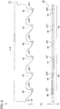
- Each of the sawtooth groups 42 includes, unlike each of the sawtooth groups 30 of the hard tip band-saw blade 28 (refer to Fig. 4(a)(b) ), two first sawtooth subgroups 32 and one second sawtooth subgroup 34.
- each sawtooth group 42 is configured to have 10 sawteeth.
- L indicates a left direction
- R a right direction
- F a saw blade forwarding direction
- a hard tip band-saw blade 44 of the comparison example 1 is a cutting tool corresponding to the first prior-arm hard tip band-saw blade and has alternating sawtooth groups 46 each being a combination of a plurality of sawteeth.
- the structure of the hard tip band-saw blade 44 will briefly be explained.
- Each of the sawtooth groups 46 includes, as the plurality of sawteeth, a leading tooth 48 and a following tooth 50.
- each sawtooth group 46 is formed with two sawteeth.
- the leading tooth 48 has, on its tooth top side, a hard tip 48T made of cemented carbide and is configured like the first leading tooth 18 in the first sawtooth subgroup 14 of the hard tip band-saw blade 10 (refer to Fig. 1(a)(b) ).
- the following tooth 50 has, on its tooth top side, a hard tip 50T made of cemented carbide and is configured like the first following tooth 20 in the first sawtooth subgroup 14 of the hard tip band-saw blade 10 (refer to Fig. 1(a)(b) ).
- a hard tip band-saw blade 52 of the comparison example 2 is a cutting tool corresponding to the second prior-art hard tip band-saw blade and has alternating sawtooth groups 54 each being a combination of a plurality of sawteeth.
- the structure of the hard tip band-saw blade 52 will briefly be explained.
- Each of the sawtooth groups 54 includes, as the plurality of sawteeth, a leading tooth 56, a first following tooth 58, and a second following tooth 60.
- each sawtooth group 54 is formed with three sawteeth.
- the leading tooth 56 has, on its tooth top side, a hard tip 56T made of cemented carbide and is configured like the second leading tooth 22 in the second sawtooth subgroup 16 of the hard tip band-saw blade 10 (refer to Fig. 1(a)(b) ).
- the first following tooth 58 has, on its tooth top side, a hard tip 58T made of cemented carbide and is configured like the second following tooth 24 in the second sawtooth subgroup 16 of the hard tip band-saw blade 10 (refer to Fig. 1(a)(b) ).
- the second following tooth 60 has, on its tooth top side, a hard tip 60T made of cemented carbide and is configured like the third following tooth 26 in the second sawtooth subgroup 16 of the hard tip band-saw blade 10 (refer to Fig. 1(a)(b) ).
- the hard tip band-saw blade 10 according to the first embodiment is experimentally made as the embodiment product 1, the hard tip band-saw blade 28 according to the second embodiment as the embodiment product 2, and the hard tip band-saw blade 40 according to the third embodiment as the embodiment product 3.
- the hard tip band-saw blade 44 according to the comparison example 1 is experimentally made as the comparison product 1 and the hard tip band-saw blade 52 according to the comparison example 2 as the comparison product 2.
- the embodiment products 1 to 3 and comparison products 1 and 2 each are made to have a base-tooth-shape rake angle of 10 degrees, a base-tooth-shape clearance angle of 20 degrees, a band width of 41 mm, a band thickness of 1.3 mm, a band length of 4715 mm, and a pitch of 1.8/2 P.
- the cemented carbide tip of each of the embodiment products 1 to 3 and comparison products 1 and 2 is made of cemented carbide corresponding to K20.
- a cutting test is carried out on a workpiece made of alloy tool steel (SKD61) having a diameter of 250 mm.
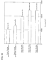
- cut areas (cumulative cut areas) of the workpiece using the embodiment products 1 to 3 and comparison products 1 and 2 are summarized in Fig. 10 .
- relationships between the number of cuts and a crooked cut amount by the embodiment products 1 to 3 and comparison products 1 and 2 are summarized in Fig. 11 .
- crooked cuts in the workpiece increase when the cut area exceeds 50000 cm2 and the hard tip band-saw blades reach their service lives.
- the embodiment product 1 it is confirmed that crooked cuts in the workpiece are sufficiently suppressed until the cut area reaches around 100000 cm2 and a stable cutting ability is demonstrated.
- the embodiment products 2 and 3 it is confirmed that crooked cuts in the workpiece do not increase even when the cut area exceeds 100000 cm2 and crooked cuts in the workpiece are more sufficiently suppressed than the case of using the embodiment product 1.
- the hard tip band-saw blade has reached its service life if the crooked cut amount in the workpiece becomes 1.0 mm or greater.
- a surface roughness (arithmetic mean roughness) Ra of a cut face of the workpiece is 12 ⁇ m to 14 ⁇ m.
- the surface roughness Ra of a cut face of the workpiece at the time of service life of the hard tip band-saw blade is about 15 ⁇ m.
- the surface roughness Ra of a cut face of the workpiece at the time when the cut area reaches to 40000 cm2 is 8 ⁇ m to 9 ⁇ m.
- the surface roughness Ra of a cut face of the workpiece at the time of service life of the hard tip band-saw blade is 10 ⁇ m or lower.
- the surface roughness Ra of a cut face of the workpiece at the time when the cut area reaches to 100000 cm2 is 8 ⁇ m to 9 ⁇ m.
- the inventors of this application obtain a first knowledge that forming a sawtooth group with a first sawtooth subgroup corresponding to the sawtooth group of the first prior-art hard band-saw blade and a second sawtooth subgroup corresponding to the sawtooth group of the second prior-art hard band-saw blade is able to sufficiently suppress a crooked cut in a workpiece made of hard metal such as steel, and at the same time, improve a cut face accuracy of the workpiece.
- the inventors of this application obtain a second knowledge that arranging, as a middle tooth, a left-right symmetrical sawtooth between a first leading tooth and a first following tooth in the first sawtooth subgroup, as well as between a second leading tooth and a second following tooth in the second sawtooth subgroup more sufficiently suppresses a crooked cut in a workpiece made of hard metal, and at the same time, more improves a cut face accuracy of the workpiece.
- straight movement of the hard tip band-saw blade can be maintained even if the first following tooth, which is a left-right symmetrical plectrum tooth, involves accuracy variations due to manufacturing errors.
- the first following tooth which is a left-right symmetrical plectrum tooth
- a crooked cut or the like in a workpiece can sufficiently be suppressed to improve a cut face accuracy of the workpiece and the service life of the hard tip band-saw blade.
Landscapes
- Engineering & Computer Science (AREA)
- Mechanical Engineering (AREA)
- Sawing (AREA)
Abstract
Description
- The present invention relates to a hard tip band-saw blade used when a band saw carries out a sawing process (cutting process) on a workpiece (metal work) and having a hard tip made of hard material on the tooth top side of each sawtooth.
- In recent years, hard tip band-saw blades of excellent cutting ability are more widely used than bimetal band-saw blades having a body made of strengthened alloy steel and a cutting part made of high-speed tool steel.
- The hard tip band-saw blade has, on the tooth top side of each sawtooth (cutting tooth), a hard tip made of hard material such as cemented carbide .
- Typical hard tip band-saw blades that can be mentioned are the following two type of hard tip band-saw blades.
- A first prior-art hard tip band-saw blade includes alternating sawtooth groups each being a combination of a plurality of sawteeth. The plurality of sawteeth in each sawtooth group include a leading tooth and a following tooth.
- The leading tooth is formed in a left-right symmetrical shape. At a tooth top corner part on each of the left and right sides of a hard tip of the leading tooth, a chamfer (corner chamfer) is formed. Namely, the leading tooth is a bevel tooth that is one of left-right symmetrical sawteeth.
- The following tooth is arranged to follow the leading tooth. The tooth height size thereof is set to be smaller than the tooth height size of the leading tooth. The following tooth is formed in a left-right symmetrical shape that widens toward a tooth top edge (tooth top ridge line) side like a plectrum (trapezoid or dovetail (dove tail shape)).
- In other words, the following tooth is a plectrum tooth (trapezoidal tooth or dovetailed tooth (dove tail shaped tooth)) that is one of the left-right symmetrical sawteeth (refer to Comparison Example 1 to be explained later).
- Here, in the first hard tip band-saw blade, each tooth top corner part of the hard tip of the following tooth most outwardly protrudes in a left-right direction. Namely, in each sawtooth group, the following tooth is a finishing tooth to finish a cut face of a workpiece.
- The second prior-art hard tip band-saw blade includes alternating sawtooth groups each being a combination of a plurality of sawteeth.
- The plurality of sawteeth in each sawtooth group include a leading tooth, a first following tooth, and a second following tooth.
- The leading tooth is formed in a left-right symmetrical shape. At a tooth top corner part on each of the left and right sides of a hard tip of the leading tooth, a chamfer is formed. In other words, the leading tooth is a bevel tooth that is one of the left-right symmetrical sawteeth.
- The first following tooth is arranged to follow the leading tooth. The tooth height size thereof is set to be smaller than the tooth height size of the leading tooth. The first following tooth is formed like a plectrum (trapezoid or dovetail (dove tail shape)) that widens toward a tooth top edge side. At a tooth top corner part on a left/right first side of a hard tip thereof, a chamfer is formed.
- In other words, the first following tooth is a one-side plectrum tooth (set tooth or one-side dovetailed tooth) that is one of left-right asymmetrical sawteeth.
- The second following tooth is arranged to follow the first following tooth. The tooth height size thereof is set to be the same as the tooth height size of the first following tooth. The second following tooth is formed like a plectrum (trapezoid or dovetail) that widens toward a tooth top edge side. At a tooth top corner part on a left/right second side of a hart tip thereof, a chamfer is formed.
- In other words, the second following tooth is a one-side plectrum tooth (set tooth or one-side dovetailed tooth) that is one of the left-right asymmetrical sawteeth (refer to Comparison Example 2 to be explained later).
- Here, in the second hard tip band-saw blade, a tooth top corner part on a left/right second side of the hard tip of the first following tooth and a tooth top corner part on a left/right first side of the hard tip of the second following tooth most outwardly protrude in the left-right direction. Namely, in each sawtooth group, the first following tooth and second following tooth are finishing teeth to finish a cut face of a workpiece.
- In addition, related arts concerning the hard tip band-saw blades are shown in
Patent Literatures 1 to 3. -
- Patent Literature 1: Japanese Patent Publication No.
3370166 - Patent Literature 2: Japanese Unexamined Patent Application Publication No.
2000-263327 - Patent Literature 3: Japanese Unexamined Patent Application Publication No.
2014-176956 - By the way, in the first prior-art hard tip band-saw blade that is conducting a cutting process of a workpiece of hard metal such as steel, the hard tip of the following tooth is in a state of being restricted in the left-right direction by a cut groove of the workpiece.
- Due to this, if the following tooth that is a left-right symmetrical plectrum tooth involves accuracy (left-right symmetry) variations due to manufacturing errors, cutting resistance in the left-right direction will vary to easily cause a crooked cut in the workpiece or a tooth chipping of the hard tip band-saw blade. This causes a problem that it is hard to improve a cut face accuracy of the workpiece or a service life of the hard tip band-saw blade.
- Here, the crooked cut in a workpiece is a phenomenon caused by a bend of the hard tip band-saw blade depending on material of the workpiece or the worn state, feed rate, cutting rate, and the like of the hard tip band-saw blade, to make a cut face of the workpiece spherical or slanted. The crooked cut of a workpiece results in providing an unacceptable product due to an inferior cut face accuracy of the workpiece or damaging the hard tip band-saw blade.
- Further, according to the second prior-art hard tip band-saw blade, when the tooth top corner part on the left/right second side of the hard tip of the first following tooth and the tooth top corner part on the left/right first side of the hard tip of the second following tooth receive cutting resistance in the left-right direction, elastic deforming force is applied to the body and tooth bottom of the hard tip band-saw blade. This results in enlarging vibrations (variations) of the first following tooth or second following tooth in the left-right direction to lower a cut face accuracy of the workpiece or cause a body breakage of the hard tip band-saw blade.
- A hard tip band-saw blade used when carrying out a cutting process on a workpiece that is mainly made of soft metal such as aluminum alloy (hereinafter referred to as a soft metal cutting hard tip band-saw blade, if necessary) has a reduced number of finishing teeth in each sawtooth group.
- This is because the cutting ability of the soft metal cutting hard tip band-saw blade more depends on the hardness (softness) and material of a workpiece than the cutting amount (work amount) borne by a single sawtooth. Namely, the soft metal cutting hard tip band-saw blade is inappropriate to cut a workpiece made of hard metal such as steel.
- The present invention has been made in consideration of the above-mentioned circumstances and an object thereof is to provide a hard tip band-saw blade having novel configuration capable of solving the above-mentioned problems.
- According to a first aspect of the present invention, the hard tip band-saw blade used when carrying out a sawing process (cutting process) on a workpiece includes alternating sawtooth groups each being a combination of a plurality of sawteeth (cutting teeth) with each sawtooth being provided with a hard tip of hard material on a tooth top side of the sawtooth, wherein each sawtooth group is formed from two sawtooth subgroups, the first sawtooth subgroup has a plurality of sawteeth that include a first leading tooth (first bevel tooth) formed in a left-right symmetrical shape and having a chamfer (corner chamfer) at a tooth top corner part on each of left and right sides of the hard tip and a first following tooth (plectrum tooth or dovetailed tooth (dove tail shaped tooth)) arranged to follow the first leading tooth, set to be smaller than the first leading tooth in tooth height size, and formed in a left-right symmetrical shape that widens toward a tooth top edge (tooth top ridge line) side like a plectrum (trapezoid or dovetail (dove tail shape)), the second sawtooth subgroup has a plurality of sawteeth that include a second leading tooth (second bevel tooth) set to be the same as the first leading tooth in tooth height size, formed in a left-right symmetrical shape, and having a chamfer (corner chamfer) at a tooth top corner part on each of left and right sides of the hard tip, a second following tooth (one-side plectrum tooth or one-side dovetailed tooth) arranged to follow the second leading tooth, set to be the same as the first following tooth in tooth height size, formed to widen toward a tooth top edge side like a plectrum (trapezoid or dovetail (dove tail shape)), and having a chamfer (corner chamfer) at a tooth top corner part on a left/right first side of the hard tip, and a third following tooth (one-side plectrum tooth or one-side dovetailed tooth) arranged to follow the second following tooth, set to be the same as the first following tooth in tooth height size, formed to widen toward a tooth top edge side like a plectrum (trapezoid or dovetail (dove tail shape)), and having a corner chamfer at a tooth top corner part on a left/right second side of the hard tip, and each tooth top corner part of the hard tip of the first following tooth, the tooth top corner part on the left/right second side of the hard tip of the second following tooth, and the tooth top corner part on the left/right first side of the hard tip of the third following tooth most outwardly protrude in a left-right direction.
- According to the first aspect of the present invention, the first sawtooth subgroup includes the first leading tooth and first following tooth of the above-mentioned configurations and corresponds to the sawtooth group of the first prior-art hard tip band-saw blade. The second sawtooth subgroup includes the second leading tooth, second following tooth, and third following tooth of the above-mentioned configurations and corresponds to the sawtooth group of the second prior-art hard tip band-saw blade. The hard tip of the first leading tooth, the hard tip of the first following tooth, and the hard tip of the second leading tooth each have a left-right symmetrical shape. These configurations heightens the ratio of the number of left-right symmetrical sawteeth to the total number of sawteeth in each sawtooth group, to improve straight movement of the hard tip band-saw blade.
- When the tooth top corner part on the left/right second side of the second following tooth receives cutting resistance in the left-right direction, the third following tooth elastically deforms in a left/right first side direction, and when the tooth top corner part on the left/right first side of the hard tip of the third following tooth receives cutting resistance in the left/right direction, the second following tooth elastically deforms in a left/right second direction. With this, even if the first following tooth that is the left-right symmetrical plectrum tooth involves accuracy (left-right symmetry) variations due to manufacturing errors, the elastic deformations of the second following tooth and third following tooth in the left-right direction absorb the manufacturing errors, thereby maintaining straight movement of the hard tip band-saw blade.
- According to a second aspect of the present invention, in addition to the configurations of the first aspect of the present invention, the first sawtooth subgroup includes a first middle tooth (first middle bevel tooth) arranged in the middle between the first leading tooth and the first following tooth, set to be smaller than the first leading tooth and larger than the first following tooth in tooth height size, formed in a left-right symmetrical shape, and having a chamfer at a tooth top corner part on each of left and right sides of the hard tip and the second sawtooth subgroup includes a second middle tooth (second middle bevel tooth) arranged in the middle between the second leading tooth and the second following tooth, set to be the same as the first middle tooth in tooth height size, formed in a left-right symmetrical shape, and having a chamfer at a tooth top corner part on each of left and right sides of the hard tip.
- According to the second aspect of the present invention, the first middle tooth and second middle tooth each have a left-right symmetrical shape. This improves the ratio of the number of left-right symmetrical sawteeth to the total number of sawteeth in each sawtooth group, thereby improving straight motion of the hard tip band-saw blade.
- In addition to the first leading tooth and second leading tooth, the first middle tooth and second middle tooth are bevel teeth, and therefore, a cutting amount (work amount) by the bevel teeth can be distributed among them in a cut groove depth direction of a workpiece.
-
- [
Fig. 1] Fig. 1 is a diagram showing a hard tip band-saw blade according to a first embodiment, in which (a) shows a left side face of a part of the hard tip band-saw blade and (b) shows the part of the hard tip band-saw blade seen from a cutting edge side (tooth top side). - [
Fig. 2] Fig. 2 is a diagram showing the hard tip band-saw blade according to the first embodiment, in which (a) is a diagram showing a first leading tooth of the hard tip band-saw blade seen from a saw blade forwarding direction, (b) is a diagram showing a first following tooth of the hard tip band-saw blade seen from the saw blade forwarding direction, (c) is a diagram showing a second leading tooth of the hard tip band-saw blade seen from the saw blade forwarding direction, (d) is a diagram showing a second following tooth of the hard tip band-saw blade seen from the saw blade forwarding direction, and (e) is a diagram showing a third following tooth of the hard tip band-saw blade seen from the saw blade forwarding direction. - [
Fig. 3] Fig. 3 is an enlarged diagram showing the first leading tooth and the like of the hard tip band-saw blade according to the first embodiment seen from the saw blade forwarding direction and a state of carrying out a cutting process on a workpiece. - [
Fig. 4] Fig. 4 is a diagram showing a hard tip band-saw blade according to a second embodiment, in which (a) shows a left side face of a part of the hard tip band-saw blade and (b) shows the part of the hard tip band-saw blade seen from a cutting edge side (tooth top side). - [
Fig. 5] Fig. 5 is a diagram showing the hard tip band-saw blade according to the second embodiment, in which (a) is a diagram showing a first leading tooth of the hard tip band-saw blade seen from a saw blade forwarding direction, (b) is a diagram showing a first middle tooth of the hard tip band-saw blade seen from the saw blade forwarding direction, (c) is a diagram showing a first following tooth of the hard tip band-saw blade seen from the saw blade forwarding direction, (d) is a diagram showing a second leading tooth of the hard tip band-saw blade seen from the saw blade forwarding direction, (e) is a diagram showing a second middle tooth of the hard tip band-saw blade seen from the saw blade forwarding direction, (f) is a diagram showing a second following tooth of the hard tip band-saw blade seen from the saw blade forwarding direction, and (g) is a diagram showing a third following tooth of the hard tip band-saw blade seen from the saw blade forwarding direction. - [
Fig. 6] Fig. 6 is an enlarged diagram showing the first leading tooth and the like of the hard tip band-saw blade according to the second embodiment seen from the saw blade forwarding direction and a state of carrying out a cutting process on a workpiece. - [
Fig. 7] Fig. 7 is a diagram showing a hard tip band-saw blade according to a third embodiment, in which (a) shows a left side face of a part of the hard tip band-saw blade and (b) shows the part of the hard tip band-saw blade seen from a cutting edge side (tooth top side). - [
Fig. 8] Fig. 8 is a diagram showing a hard tip band-saw blade according to a comparison example 1, in which (a) shows a left side face of a part of the hard tip band-saw blade and (b) shows the part of the hard tip band-saw blade seen from a cutting edge side (tooth top side). - [
Fig. 9] Fig. 9 is a diagram showing a hard tip band-saw blade according to a comparison example 2, in which (a) shows a left side face of a part of the hard tip band-saw blade and (b) shows the part of the hard tip band-saw blade seen from a cutting edge side (tooth top side). - [
Fig. 10] Fig. 10 is a graph showing workpiece cut areas (cumulative cut areas) as a result of cutting test carried out onembodiment products 1 to 3 andcomparison products - [
Fig. 11] Fig. 11 is a graph showing a relationship between the number of cuts and a crooked cut amount of workpiece as a result of cutting test carried out on theembodiment products 1 to 3 andcomparison products - Hereinafter, embodiments (first to third embodiments) of the present invention will be explained with reference to the drawings.
- In the specification and claims of this application, the "left-right" direction is, in a state that the cutting edge (tooth top) of a hard tip band-saw blade is oriented downward, a left-right direction seen from a saw blade forwarding direction (a direction to move forward the hard tip band-saw blade). The "left/right first side" is any one of left and right sides. The "left/right second side" is an opposite side of the left/right first side. If the left/right first side is the right side, the left/right second side is the left side, and if the left/right first side is the left side, the left/right second side is the right side. The "leading" means ahead when seen from the saw blade forwarding direction and the "following" means hind when seen from the saw blade forwarding direction. The "saw blade center line" is a line passing through a left-right directional center of the hard tip band-saw blade.
- The "tooth height size" is a dimension from a virtual reference line (not shown in the drawings) extending along a saw back in a body of the hard tip band-saw blade to a tooth top, where the larger the tooth height size, the longer the distance from the saw back to the tooth top and the smaller the tooth height size, the shorter the distance from the saw back to the saw top. In the drawings, "L" indicates the left direction, "R" the right direction, and "F" the saw blade forwarding direction.
- As shown in
Fig. 1(a)(b) to Fig. 3 , a hard tip band-saw blade 10 according to the first embodiment is a cutting tool used when carrying out a sawing process (cutting process) by a band saw on a workpiece (metal work) made of hard metal such as steel. - The hard tip band-
saw blade 10 is endlessly structured and a body (main body) of the hard tip band-saw blade 10 is made of alloy steel of high toughness. - The hard tip band-
saw blade 10 has alternatingsawtooth groups 12 each being a combination (sawtooth pattern) of a plurality of sawteeth (cutting teeth). Each of thesawtooth groups 12 includes twosawtooth subgroups - The first
sawtooth subgroup 14 contains a plurality of sawteeth including a first leadingtooth 18 and a first followingtooth 20. The secondsawtooth subgroup 16 contains a plurality of sawteeth including a second leadingtooth 22, a second followingtooth 24, and a third followingtooth 26. In other words, each of thesawtooth groups 12 contains five sawteeth. - Here, the first leading
tooth 18 has, on its tooth top side, ahard tip 18T made of cemented carbide (hard material called cemented carbide containing, for example, tungsten carbide or cobalt). Similarly, the first followingtooth 20 has, on its tooth top side, ahard tip 20T made of cemented carbide, the second leadingtooth 22 has, on its tooth top side, ahard tip 22T made of cemented carbide, and the second followingtooth 24 has, on its tooth top side, ahard tip 24T made of cemented carbide. - The third following
tooth 26 has, on its tooth top side, ahard tip 26T made of cemented carbide. The cemented carbide may additionally contain titanium carbide and the like. Instead of using the cemented carbide as a material for forming thehard tip 18T and the like, other hard material such as cermet containing tungsten carbide and the like may be used to form thehard tip 18T and the like. - Next, structures of the first leading
tooth 18, first followingtooth 20, second leadingtooth 22, second followingtooth 24, and third followingtooth 26 will be explained in detail. - As shown in
Fig. 1 to Fig. 3 , the first leadingtooth 18 is, as mentioned above, one of the sawteeth that form the firstsawtooth subgroup 14 and is a sawtooth to form a cut groove G of a groove width S in the workpiece W. Further, the first leading tooth 18 (thehard tip 18T of the first leading tooth 18) is formed in a left-right symmetrical shape with respect to a saw blade center line M. At a tooth top corner part on each of left and right sides of thehard tip 18T of the first leadingtooth 18, a chamfer (corner chamfer) 18Tc is formed. - In other words, the first leading
tooth 18 is a first bevel tooth that is one of left-right symmetrical sawteeth. A chamfer angle θ1 of the chamfer 18Tc of thehard tip 18T of the first leadingtooth 18 with respect to a tooth top edge (tooth top ridge line) 18Tt is set to, as an example, 40 to 50 degrees. - The first following
tooth 20 is, as mentioned above, one of the sawteeth that constitute the firstsawtooth subgroup 14 and is arranged to follow the first leadingtooth 18. The first followingtooth 20 is a sawtooth to expand the cutting groove G of the workpiece W to a groove width P. The tooth height size of the first followingtooth 20 is set to be smaller than the tooth height size of the first leadingtooth 18. - Further, the first following tooth 20 (the
hard tip 20T of the first following tooth 20) is formed like a plectrum (trapezoid or dovetail (dove tail shape)) enlarging toward a tooth top edge 20Tt and is formed in a left-right symmetrical shape with respect to the saw blade center line M. - In other words, the first following
tooth 20 is a plectrum tooth or a dovetailed tooth (dove tail shaped tooth) that is one of the left-right symmetrical sawteeth. Each tooth top corner part of thehard tip 20T of the first followingtooth 20 is a protruding part (protruding edge part) B that outwardly protrudes in the left-right direction with respect to the chamfer 18Tc of thehard tip 18T of the first leadingtooth 18. - The second
leading tooth 22 is, as mentioned above, one of the sawteeth that constitute the secondsawtooth subgroup 16 and is a sawtooth to form the cut groove G of the groove width S in the workpiece W. The tooth height size of the second leadingtooth 22 is set to be the same as the tooth height size of the first leadingtooth 18. Further, the second leading tooth 22 (thehard tip 22T of the second leading tooth 22) is formed in a left-right symmetrical shape with respect to the saw blade center line M. - At a tooth top corner part on each of the left and right sides of the
hard tip 22T of the second leadingtooth 22, a chamfer (corner chamfer) 22Tc is formed. In other words, the second leadingtooth 22 is a second bevel tooth that is one of the left-right symmetrical sawteeth. A chamfer angle θ2 of the chamfer 22Tc of thehard tip 22T of the second leadingtooth 22 with respect to a tooth top edge 22Tt is set to be equal to the chamfer angle θ1 of the chamfer 18Tc of thehard tip 18T of the first leadingtooth 18 with respect to the tooth top edge (tooth top ridge line) 18Tt. In other words, thehard tip 22T of the second leadingtooth 22 is formed in the same shape as thehard tip 18T of the first leadingtooth 18. - The second following
tooth 24 is, as mentioned above, one of the sawteeth that constitute the secondsawtooth subgroup 16 and is arranged to follow the second leadingtooth 22. The second followingtooth 24 is a sawtooth that cooperates with the third followingtooth 26 to expand the cut groove G to the groove width P. The tooth height size of the second followingtooth 24 is set to be the same as the tooth height size of the first followingtooth 20. - Further, the second following tooth 24 (the
hard tip 24T of the second following tooth 24) is formed like a plectrum that widens toward a tooth top edge 24Tt. At a tooth top corner part on the right side of thehard tip 24T of the second followingtooth 24, a chamfer (corner chamfer) 24Tc is formed. In other words, the second followingtooth 24 is a one-side plectrum tooth (set tooth or one-side dovetailed tooth) that is one of left-right asymmetrical sawteeth. - A chamfer angle θ3 of the chamfer 24Tc of the second following
tooth 24 with respect to the tooth top edge 24Tt is set to be smaller than the chamfer angle θ2 of the second leadingtooth 22 and is set to, as an example, 20 to 40 degrees. Further, a tooth top corner part on the left side of thehard tip 24T of the second followingtooth 24 is a protruding part B that outwardly protrudes in the left-right direction with respect to the chamfer 22Tc of thehard tip 22T of the second leadingtooth 22. - The third following
tooth 26 is, as mentioned above, one of the sawteeth that constitute the secondsawtooth subgroup 16 and is arranged to follow the second followingtooth 24. The third followingtooth 26 is a sawtooth that cooperates with the second followingtooth 24 to expand the cut groove G of the workpiece W to the groove width P. The tooth height size of the third followingtooth 26 is set to be the same as the tooth height size of the first followingtooth 20. Further, the third following tooth 26 (thehard tip 26T of the third following tooth 26) is formed like a plectrum that widens toward a tooth top edge 26Tt. At a tooth top corner part on the left side of thehard tip 26T of the third followingtooth 26, a chamfer (corner chamfer) 26Tc is formed. In other words, the third followingtooth 26 is a one-side plectrum tooth (set tooth or one-side dovetailed tooth) that is one of the left-right asymmetrical sawteeth. - A chamfer angle θ4 of the chamfer 26Tc of the
hard tip 26T of the third followingtooth 26 with respect to the tooth top edge 26Tt is set to be the same as the chamfer angle θ3 of the chamfer 24Tc of thehard tip 24T of the second followingtooth 24 with respect to the tooth top edge 24Tt. Further, a tooth top corner part on the right side of thehard tip 26T of the third followingtooth 26 is a protruding part B that outwardly protrudes in the left-right direction with respect to the chamfer 22Tc of thehard tip 22T of the second leadingtooth 22. - By the way, instead of forming the chamfer 24Tc at the tooth top corner part on the right side of the
hard tip 24T of the second followingtooth 24, a chamfer (not shown) may be formed at the tooth top corner part on the left side of thehard tip 24T of the second followingtooth 24. In this case, instead of forming the chamfer 26Tc at the tooth top corner part on the left side of thehard tip 26T of the third followingtooth 26, a chamfer (not shown) is formed at the tooth top corner part on the right side of thehard tip 26T of the third followingtooth 26. - Each tooth top corner part of the
hard tip 20T of the first followingtooth 20, the tooth top corner part on the left side of thehard tip 24T of the second followingtooth 24, and the tooth top corner part on the right side of thehard tip 26T of the third followingtooth 26 each most outwardly protrude in the left-right direction. In other words, outer ends 20Te in the left-right direction of the tooth top edge (tooth top ridge line) 20Tt of thehard tip 20T of the first followingtooth 20, an outer end (left end) 24Te in the left-right direction of the tooth top edge 24Tt of thehard tip 24T of the second followingtooth 24, and an outer end (right end) 26Te in the left-right direction of the tooth top edge 26Tt of thehard tip 26T of the third followingtooth 26 each are positioned most outwardly in the left-right direction. - Namely, in each of the
sawtooth groups 12, the first followingtooth 20, second followingtooth 24, and third followingtooth 26 are finishing teeth to finish a cut face of the workpiece W. - The hard tips of the sawteeth that cut a center part (part corresponding to the groove width S) in a groove width direction of the cut groove G of the workpiece W are the
hard tip 18T of the first leadingtooth 18 and thehard tip 22T of the second leadingtooth 22. The hard tips of the sawteeth that cut a left end part (part corresponding to a groove width of (P - S) / 2 on the left side) in the groove width direction of the cut groove G of the workpiece W are thehard tip 20T of the first followingtooth 20 and thehard tip 24T of the second followingtooth 24. The hard tips of the sawteeth that cut a right end part (part corresponding to a groove width of (P - S) / 2 on the right side) in the groove width direction of the cut groove G of the workpiece W are thehard tip 20T of the first followingtooth 20 and thehard tip 26T of the third followingtooth 26. In other words, with the cut groove G to be formed in the workpiece W being divided into three sections in the groove width direction, each of thesawtooth groups 12 includes the same number of and a plurality of (two) sawteeth to cut the respective groove width sections of the cut groove G of the workpiece W. - Next, operation and effect of the first embodiment will be explained.
- When the band saw is driven, the hard tip band-
saw blade 10 cyclically runs in the saw blade forwarding direction, and at the same time, the hard tip band-saw blade 10 moves in a cutting direction (a direction to approach the workpiece W). Then, in a cutting area of the workpiece W by the band saw, the first leadingtooth 18 forms the cut groove G of the groove width S in the workpiece W and the first followingtooth 20 widens the cut groove G of the workpiece W to the groove width P. Also, in the cutting area of the workpiece W by the band saw, the second leadingtooth 22 forms the cut groove G of the groove width S and the second followingtooth 24 and third followingtooth 26 widen the cut groove G of the workpiece W to the groove width P. The actions mentioned above are continuously carried out so that the first followingtooth 20, second followingtooth 24, and third followingtooth 26 finish a cut face of the workpiece W. With this, the hard tip band-saw blade 10 is able to carry out a required sawing process (cutting process) on the workpiece W. - The first
sawtooth subgroup 14 includes the first leadingtooth 18 and first followingtooth 20 of the above-mentioned configurations and corresponds to the sawtooth group of the first prior-art hard tip band-saw blade. The secondsawtooth subgroup 16 includes the second leadingtooth 22, second followingtooth 24, and third followingtooth 26 of the above-mentioned configurations and corresponds to the sawtooth group of the second prior-art hard tip band-saw blade. Among them, the first leadingtooth 18, first followingtooth 20, and second leadingtooth 22 each are left-right symmetrical sawteeth. This heightens the ratio of the number of left-right symmetrical sawteeth to the total number of sawteeth in eachsawtooth group 12. - When the tooth top corner part on the left side of the
hard tip 24T of the second followingtooth 24 receives left-right directional cutting resistance, the second followingtooth 24 and the body (the body of the hard tip band-saw blade 10) elastically deforms in the right direction. When the tooth top corner part on the right side of thehard tip 26T of the third followingtooth 26 receives left-right directional cutting resistance, the third followingtooth 26 and the body elastically deforms in the left direction. In other words, the second followingtooth 24, third followingtooth 26, and body elastically deform while keeping a balanced state in the left-right direction. With this, even if the first leadingtooth 18, which is a left-right symmetrical plectrum tooth, involves accuracy (left-right symmetry) variations due to manufacturing errors, the left-right directional elastic deformations of the second followingtooth 24, third followingtooth 26, and body absorb the manufacturing errors, thereby keeping straight movement of the hard tip band-saw blade 10. In addition, it sufficiently prevents the tooth breakage of the second followingtooth 24 and third followingtooth 26. - With the cut groove G formed in the workpiece W being divided into three sections in the groove width direction, each of the
sawtooth groups 12 has the same number of and a plurality of sawteeth to cut the respective sections in the groove width direction of the cut groove G in the workpiece W. This results in distributing cutting resistance acting on the sawteeth over the sawteeth in eachsawtooth group 12 and equalizing work amount of the sawteeth in eachsawtooth group 12. - In this way, according to the first embodiment, even if the first leading
tooth 18, which is a left-right symmetrical plectrum tooth, involves accuracy variations due to manufacturing errors, it is possible to maintain straight movement of the hard tip band-saw blade 10. As a result, the first embodiment is able to sufficiently suppress a crooked cut or the like by the hard tip band-saw blade 10 and improve the cut face accuracy of a workpiece W and the service life of the hard tip band-saw blade 10. In particular, it is able to distribute cutting resistance among the sawteeth in each of thesawtooth groups 12 and substantially equalize work amount of the sawteeth in eachsawtooth group 12, thereby further improving the service life of the hard tip band-saw blade 10. - As shown in
Fig. 4(a)(b) to Fig. 6 , a hard tip band-saw blade 28 according to the second embodiment has a configuration similar to that of the hard tip band-saw blade 10 according to the first embodiment (refer toFig. 1(a)(b) ). Hereunder, in the configuration of the hard tip band-saw blade 28, only part differing from the hard tip band-saw blade 10 will be explained. Among a plurality of structural elements of the hard tip band-saw blade 28, those corresponding to the structural elements of the hard tip band-saw blade 10 are represented with the same reference marks in the drawings. - The hard tip band-
saw blade 28 has alternatingsawtooth groups 30 each being a combination (sawtooth pattern) of a plurality of sawteeth (cutting teeth). Each of thesawtooth groups 30 includes twosawtooth subgroups sawtooth subgroup 32 includes as the plurality of sawteeth, unlike the firstsawtooth subgroup 14 of the hard tip band-saw blade 10 (refer toFig. 1(a),(b) ), a first leadingtooth 18 and a first followingtooth 20, and in addition, a firstmiddle tooth 36. The secondsawtooth subgroup 34 includes as the plurality of sawteeth, unlike the secondsawtooth subgroup 16 of the hard tip band-saw blade 10 (refer toFig. 1(a)(b) ), a second leadingtooth 22, a second followingtooth 24, and a third followingtooth 26, and in addition, a secondmiddle tooth 38. In other words, each of thesawtooth groups 30 includes seven sawteeth. - Here, the first
middle tooth 36 has, on its tooth top side, ahard tip 36T made of cemented carbide (hard material called cemented carbide containing, for example, tungsten carbide or cobalt) . The secondmiddle tooth 38 has, on its tooth top side, ahard tip 38T made of cemented carbide. The cemented carbide may additionally contain titanium carbide or the like. Instead of employing the cemented carbide as a material to form thehard tip 36T and the like, other hard material such as cermet containing tungsten carbide or the like may be employed as a material to form thehard tip 36T and the like. - The first
middle tooth 36 is, as mentioned above, one of the sawteeth that form the firstsawtooth subgroup 32 and is arranged between the first leadingtooth 18 and the first followingtooth 20. The firstmiddle tooth 36 is a sawtooth to widen a cut groove G in a workpiece W to a groove width K. The tooth height size of the firstmiddle tooth 36 is set to be smaller than the tooth height size of the first leadingtooth 18 and larger than the tooth height size of the first followingtooth 20. Further, the first middle tooth 36 (thehard tip 36T of the first middle tooth 36) is formed in a left-right symmetrical shape with respect to a saw blade center line M. At a tooth top corner part on each of left and right sides of thehard tip 36T of the firstmiddle tooth 36, a chamfer (corner chamfer) 36Tc is formed. In other words, the firstmiddle tooth 36 is a first middle bevel tooth that is one of left-right symmetrical sawteeth. A chamfer angle θ5 of the chamfer 36Tc of thehard tip 36T of the firstmiddle tooth 36 with respect to a tooth top edge (tooth top ridge line) 36Tt is set to be the same as that of the chamfer 18Tc of thehard tip 18T of the first leadingtooth 18 with respect to the tooth top edge 18Tt. - The second
middle tooth 38 is, as mentioned above, one of the sawteeth that form the secondsawtooth subgroup 34 and is arranged between the second leadingtooth 22 and the second followingtooth 24. The secondmiddle tooth 38 is a sawtooth to widen the cut groove G in the workpiece W to a groove width K. The tooth height size of the secondmiddle tooth 38 is set to be the same as the tooth height size of the firstmiddle tooth 36. Further, the second middle tooth 38 (thehard tip 38T of the second middle tooth 38) is formed in a left-right symmetrical shape with respect to the saw blade center line M. At a tooth top corner part on each of left and right sides of thehard tip 38T of the secondmiddle tooth 38, a chamfer (corner chamfer) 38Tc is formed. In other words, the secondmiddle tooth 38 is a second middle bevel tooth that is one of left-right symmetrical sawteeth. A chamfer angle θ6 of the chamfer 38Tc with respect to a tooth top edge 38Tt of thehard tip 38T of the secondmiddle tooth 38 is set to be the same as that of the chamfer 36Tc with respect to the tooth top edge 36Tt of thehard tip 36T of the firstmiddle tooth 36. In other words, thehard tip 38T of the secondmiddle tooth 38 is formed in the same shape as thehard tip 36T of the firstmiddle tooth 36. - Sawtooth hard tips to cut a center part (part corresponding to the groove width S) in a groove width direction of the cut groove G of the workpiece W are the
hard tip 18T of the first leadingtooth 18 and thehard tip 22T of the second leadingtooth 22. Sawtooth hard tips to cut left and right sides (sections each corresponding to a groove width of (K - S) / 2) of the center part in the groove width direction of the cut groove G of the workpiece W are thehard tip 36T of the firstmiddle tooth 36 and thehard tip 38T of the secondmiddle tooth 38. Sawtooth hard tips to cut a left end section (a section corresponding to a left groove width (P - K) / 2) in the groove width direction of the cut groove G of the workpiece W are thehard tip 20T of the first followingtooth 20 and thehard tip 24T of the second followingtooth 24. Sawtooth hard tips to cut a right end section (a section corresponding to a right groove width of (P - K) / 2) in the groove width direction of the cut groove G of the workpiece W are thehard tip 20T of the first followingtooth 20 and thehard tip 26T of the third followingtooth 26. In other words, with the cut groove G formed in the workpiece W being divided into the five sections in the groove width direction, the numbers of sawteeth to cut the respective sections in the groove width direction of the cut groove G of the workpiece W in each of thesawtooth groups 30 are equal to one another and each are plural (two). - Next, operation and effect of the second embodiment will be explained.
- When the band saw is driven, the hard tip band-
saw blade 28 cyclically runs in the saw blade forwarding direction, and at the same time, the hard tip band-saw blade 28 moves in a cutting direction (a direction to approach the workpiece W). Then, in a cutting area of the workpiece W by the band saw, the first leadingtooth 18 forms the cut groove G of the groove width S in the workpiece W, the firstmiddle tooth 36 widens the cut groove G of the workpiece W to the groove width K, and the first followingtooth 20 widens the cut groove G of the workpiece W to the groove width P. Also, in the cutting area of the workpiece W by the band saw, the second leadingtooth 22 forms the cut groove G of the groove width S in the workpiece W, the secondmiddle tooth 38 widens the cut groove G of the workpiece W to the groove width K, and the second followingtooth 24 and third followingtooth 26 widen the cut groove G of the workpiece W to the groove width P. Thereafter, the actions mentioned above are continuously carried out so that the first followingtooth 20, second followingtooth 24, and third followingtooth 26 finish a cut face of the workpiece W. With this, the hard tip band-saw blade 28 is able to carry out a required sawing process (cutting process) on the workpiece W. - The first
sawtooth subgroup 32 includes the first leadingtooth 18 and first followingtooth 20 of the above-mentioned configurations and corresponds to the sawtooth group of the first prior-art hard tip band-saw blade. Further, the secondsawtooth subgroup 34 includes the second leadingtooth 22, second followingtooth 24, and third followingtooth 26 of the above-mentioned configurations and corresponds to the sawtooth group of the second prior-art hard tip band-saw blade. The first leadingtooth 18, firstmiddle tooth 36, first followingtooth 20, secondmiddle tooth 38, and second leadingtooth 22 each are left-right symmetrical sawteeth. This increases the ratio of the number of left-right symmetrical sawteeth to the total number of sawteeth in each of thesawtooth groups 30, thereby improving straight movement of the hard tip band-saw blade 28. - Similar to the operation of the first embodiment, accuracy (left-right symmetry) variations due to manufacturing errors of the first following
tooth 20 that is a left-right symmetrical plectrum tooth can be absorbed by left-right directional elastic deformations of the second followingtooth 24 and third followingtooth 26, to maintain straight movement of the hard tip band-saw blade 28. In addition, it sufficiently prevents tooth breakage of the second followingtooth 24 and third followingtooth 26. - With the cut groove G formed in the workpiece W being divided into five sections in the groove width direction, each of the
sawtooth groups 30 has the same number of and a plurality of sawteeth to cut the respective sections in the groove width direction of the cut groove G of the workpiece W. This results in distributing cutting resistance acting on the sawteeth over the sawteeth in eachsawtooth group 30 and equalizing work amount of the sawteeth in eachsawtooth group 30. - In addition to the first leading
tooth 18 and second leadingtooth 22, the firstmiddle tooth 36 and secondmiddle tooth 38 each are bevel teeth so that cutting amount (work amount) in a depth direction of the cut groove G of the workpiece W can be distributed among the bevel teeth. - In this way, according to the second embodiment, even if the first leading
tooth 18, which is a left-right symmetrical plectrum tooth, involves accuracy variations due to manufacturing errors, it is possible to sufficiently suppress a crooked cut by the hard tip band-saw blade 28 to further elongate the service life of the hard tip band-saw blade 28 and further improve a cut face accuracy of the workpiece. In particular, it is possible to distribute cutting resistance among the sawteeth in eachsawtooth group 30, nearly equalize work amount of the sawteeth in eachsawtooth group 30, and distribute cutting amount (work amount) in the depth direction of the cut groove G of the workpiece W among the respective bevel teeth, thereby further improving the service life of the hard tip band-saw blade 28. - As shown in
Fig. 7(a)(b) , a hard tip band-saw blade 40 according to the third embodiment is configured similar to the hard tip band-saw blade 28 according to the second embodiment (refer toFig. 4(a)(b) ). Hereunder, in the configuration of the hard tip band-saw blade 40, only part differing from the hard tip band-saw blade 28 will be explained. Among a plurality of structural elements of the hard tip band-saw blade 40, those corresponding to the structural elements of the hard tip band-saw blade 28 are represented with the same reference marks in the drawings. - The hard tip band-
saw blade 40 has alternatingsawtooth groups 42 each being a combination (sawtooth pattern) of a plurality of sawteeth (cutting teeth). Each of thesawtooth groups 42 includes, unlike each of thesawtooth groups 30 of the hard tip band-saw blade 28 (refer toFig. 4(a)(b) ), two firstsawtooth subgroups 32 and one secondsawtooth subgroup 34. In other words, eachsawtooth group 42 is configured to have 10 sawteeth. - According to the third embodiment, operation and effect are similar to those of the second embodiment.
- The present invention is not limited to the above-mentioned embodiments and is achievable in various forms through proper modifications. The scope of rights covered by the present invention is not limited to the above-mentioned embodiments.
- Practical examples (comparison examples 1 and 2,
embodiment products 1 to 3, andcomparison products 1 and 2) and a cutting test will be explained with reference to the drawings. - In the drawings, "L" indicates a left direction, "R" a right direction, and "F" a saw blade forwarding direction.
- As shown in
Fig. 8(a)(b) , a hard tip band-saw blade 44 of the comparison example 1 is a cutting tool corresponding to the first prior-arm hard tip band-saw blade and has alternatingsawtooth groups 46 each being a combination of a plurality of sawteeth. Hereunder, the structure of the hard tip band-saw blade 44 will briefly be explained. - Each of the
sawtooth groups 46 includes, as the plurality of sawteeth, a leadingtooth 48 and a followingtooth 50. In other words, eachsawtooth group 46 is formed with two sawteeth. Here, the leadingtooth 48 has, on its tooth top side, ahard tip 48T made of cemented carbide and is configured like the first leadingtooth 18 in the firstsawtooth subgroup 14 of the hard tip band-saw blade 10 (refer toFig. 1(a)(b) ). The followingtooth 50 has, on its tooth top side, ahard tip 50T made of cemented carbide and is configured like the first followingtooth 20 in the firstsawtooth subgroup 14 of the hard tip band-saw blade 10 (refer toFig. 1(a)(b) ). - As shown in
Fig. 9(a)(b) , a hard tip band-saw blade 52 of the comparison example 2 is a cutting tool corresponding to the second prior-art hard tip band-saw blade and has alternatingsawtooth groups 54 each being a combination of a plurality of sawteeth. Hereunder, the structure of the hard tip band-saw blade 52 will briefly be explained. - Each of the
sawtooth groups 54 includes, as the plurality of sawteeth, a leadingtooth 56, a first followingtooth 58, and a second followingtooth 60. In other words, eachsawtooth group 54 is formed with three sawteeth. Here, the leadingtooth 56 has, on its tooth top side, ahard tip 56T made of cemented carbide and is configured like the second leadingtooth 22 in the secondsawtooth subgroup 16 of the hard tip band-saw blade 10 (refer toFig. 1(a)(b) ). The first followingtooth 58 has, on its tooth top side, ahard tip 58T made of cemented carbide and is configured like the second followingtooth 24 in the secondsawtooth subgroup 16 of the hard tip band-saw blade 10 (refer toFig. 1(a)(b) ). The second followingtooth 60 has, on its tooth top side, ahard tip 60T made of cemented carbide and is configured like the third followingtooth 26 in the secondsawtooth subgroup 16 of the hard tip band-saw blade 10 (refer toFig. 1(a)(b) ). - The hard tip band-
saw blade 10 according to the first embodiment is experimentally made as theembodiment product 1, the hard tip band-saw blade 28 according to the second embodiment as theembodiment product 2, and the hard tip band-saw blade 40 according to the third embodiment as the embodiment product 3. The hard tip band-saw blade 44 according to the comparison example 1 is experimentally made as thecomparison product 1 and the hard tip band-saw blade 52 according to the comparison example 2 as thecomparison product 2. Theembodiment products 1 to 3 andcomparison products embodiment products 1 to 3 andcomparison products - With the use of the
embodiment products 1 to 3 andcomparison products - As a result of the cutting test, cut areas (cumulative cut areas) of the workpiece using the
embodiment products 1 to 3 andcomparison products Fig. 10 . Also, as a result of the cutting test, relationships between the number of cuts and a crooked cut amount by theembodiment products 1 to 3 andcomparison products Fig. 11 . - Namely, in the case of using the
comparison products embodiment product 1, it is confirmed that crooked cuts in the workpiece are sufficiently suppressed until the cut area reaches around 100000 cm2 and a stable cutting ability is demonstrated. In the case of using theembodiment products 2 and 3, it is confirmed that crooked cuts in the workpiece do not increase even when the cut area exceeds 100000 cm2 and crooked cuts in the workpiece are more sufficiently suppressed than the case of using theembodiment product 1. In the cutting test, it is considered that the hard tip band-saw blade has reached its service life if the crooked cut amount in the workpiece becomes 1.0 mm or greater. - An observation result of cut faces of the workpiece during the cutting test is as mentioned below.
- Namely, in the case of using the
comparison products comparison products embodiment product 1, it is confirmed that the surface roughness Ra of a cut face of the workpiece at the time of service life of the hard tip band-saw blade is 10 µm or lower. In the case of using theembodiment products 2 and 3, it is confirmed that the surface roughness Ra of a cut face of the workpiece at the time when the cut area reaches to 100000 cm2 is 8 µm to 9 µm. - From the above-mentioned cutting test result, it is clarified that the case of using the
embodiment product 1, compared to the case of using thecomparison products embodiment products 2 and 3, compared to the case of using thecomparison products - Namely, the inventors of this application obtain a first knowledge that forming a sawtooth group with a first sawtooth subgroup corresponding to the sawtooth group of the first prior-art hard band-saw blade and a second sawtooth subgroup corresponding to the sawtooth group of the second prior-art hard band-saw blade is able to sufficiently suppress a crooked cut in a workpiece made of hard metal such as steel, and at the same time, improve a cut face accuracy of the workpiece. Also the inventors of this application obtain a second knowledge that arranging, as a middle tooth, a left-right symmetrical sawtooth between a first leading tooth and a first following tooth in the first sawtooth subgroup, as well as between a second leading tooth and a second following tooth in the second sawtooth subgroup more sufficiently suppresses a crooked cut in a workpiece made of hard metal, and at the same time, more improves a cut face accuracy of the workpiece.
- According to the present invention, straight movement of the hard tip band-saw blade can be maintained even if the first following tooth, which is a left-right symmetrical plectrum tooth, involves accuracy variations due to manufacturing errors. As a result, according to the present invention, a crooked cut or the like in a workpiece can sufficiently be suppressed to improve a cut face accuracy of the workpiece and the service life of the hard tip band-saw blade.
Claims (6)
- A hard tip band-saw blade used when carrying out a cutting process on a workpiece including alternating sawtooth groups each being a combination of a plurality of sawteeth with each sawtooth being provided with a hard tip of hard material on a tooth top side of the sawtooth, wherein
each sawtooth group is formed from a first sawtooth subgroup and a second sawtooth subgroup,
the first sawtooth subgroup has a plurality of sawteeth that includea first leading tooth in which the hard tip is formed in a left-right symmetrical shape and having a chamfer at a tooth top corner part on each of left and right sides of the hard tip anda first following tooth arranged to follow the first leading tooth, set to be smaller than the first leading tooth in tooth height size, and the hard tip is formed in a left-right symmetrical shape that widens toward a tooth top edge side like a plectrum,the second sawtooth subgroup has a plurality of sawteeth that includea second leading tooth set to be the same as the first leading tooth in tooth height size, formed in a left-right symmetrical shape, and having a chamfer at a tooth top corner part on each of left and right sides of the hard tip,a second following tooth arranged to follow the second leading tooth, set to be the same as the first following tooth in tooth height size, formed to widen toward a tooth top edge side like a plectrum, and having a chamfer at a tooth top corner part on a left/right first side of the hard tip, anda third following tooth arranged to follow the second following tooth, set to be the same as the first following tooth in tooth height size, formed to widen toward a tooth top edge side like a plectrum, and having a corner chamfer at a tooth top corner part on a left/right second side of the hard tip, andeach tooth top corner part of the hard tip of the first following tooth, the tooth top corner part on the left/right second side of the hard tip of the second following tooth, and the tooth top corner part on the left/right first side of the hard tip of the third following tooth most outwardly protrude in a left-right direction. - The hard tip band-saw blade according to claim 1, wherein the first sawtooth subgroup includes a first middle tooth arranged in the middle between the first leading tooth and the first following tooth, set to be smaller than the first leading tooth and larger than the first following tooth in tooth height size, formed in a left-right symmetrical shape, and having a chamfer at a tooth top corner part on each of left and right sides of the hard tip and
the second sawtooth subgroup includes a second middle tooth arranged in the middle between the second leading tooth and the second following tooth, set to be the same as the first middle tooth in tooth height size, formed in a left-right symmetrical shape, and having a chamfer at a tooth top corner part on each of left and right sides of the hard tip. - The hard tip band-saw blade according to one of claim 1 and claim 2, wherein each tooth top corner part of the hard tip of the first following tooth is a protruding part that outwardly protrudes in the left-right direction with respect to the chamfer of the hard tip of the first leading tooth, a tooth top corner part on the left-right side of the hard tip of the second following tooth is a protruding part that outwardly protrudes in the left-right direction with respect to the chamfer of the hard tip of the second leading tooth, and a tooth top corner part on the left-right side of the hard tip of the third following tooth is a protruding part that outwardly protrudes in the left-right direction with respect to the chamfer of the hard tip of the second leading tooth.
- The hard tip band-saw blade according to one of claim 1 and claim 2, wherein with the cut groove to be formed in the workpiece being divided into a plurality of sections in the groove width direction, each of the sawtooth groups includes the same number of and a plurality of sawteeth to cut the respective groove width sections of the cut groove of the workpiece.
- The hard tip band-saw blade according to one of claim 1 and claim 2, wherein the first sawtooth subgroup and the second sawtooth subgroup in each of the sawtooth groups are one number of sawtooth subgroup.
- The hard tip band-saw blade according to one of claim 1 and claim 2, wherein the first sawtooth subgroup in each of the sawtooth groups is two number of sawtooth subgroups and the second sawtooth subgroup in each of the sawtooth groups is one number of sawtooth subgroup.
Applications Claiming Priority (2)
| Application Number | Priority Date | Filing Date | Title |
|---|---|---|---|
| JP2017033754A JP6337169B1 (en) | 2017-02-24 | 2017-02-24 | Hard insert band saw blade |
| PCT/JP2018/006164 WO2018155479A1 (en) | 2017-02-24 | 2018-02-21 | Hard tip band-saw blade |
Publications (3)
| Publication Number | Publication Date |
|---|---|
| EP3587014A1 true EP3587014A1 (en) | 2020-01-01 |
| EP3587014A4 EP3587014A4 (en) | 2020-02-19 |
| EP3587014B1 EP3587014B1 (en) | 2020-09-09 |
Family
ID=62487547
Family Applications (1)
| Application Number | Title | Priority Date | Filing Date |
|---|---|---|---|
| EP18756795.3A Active EP3587014B1 (en) | 2017-02-24 | 2018-02-21 | Hard tip band-saw blade |
Country Status (4)
| Country | Link |
|---|---|
| US (1) | US10821531B2 (en) |
| EP (1) | EP3587014B1 (en) |
| JP (1) | JP6337169B1 (en) |
| WO (1) | WO2018155479A1 (en) |
Families Citing this family (4)
| Publication number | Priority date | Publication date | Assignee | Title |
|---|---|---|---|---|
| JP6578412B1 (en) * | 2018-06-08 | 2019-09-18 | 株式会社アマダホールディングス | Manufacturing method and manufacturing apparatus for annular band saw blade |
| CN114728349B (en) * | 2019-11-14 | 2025-07-08 | 米沃奇电动工具公司 | Hole saw with large carbide overhang |
| CN111715941A (en) * | 2020-05-28 | 2020-09-29 | 新昌县智超邦金属材料科学技术研究院 | A bimetallic grinding band saw blade |
| US11986890B2 (en) * | 2022-02-07 | 2024-05-21 | The M.K. Morse Company | Carbide tip hole saw |
Family Cites Families (36)
| Publication number | Priority date | Publication date | Assignee | Title |
|---|---|---|---|---|
| US3576200A (en) * | 1969-02-26 | 1971-04-27 | Heinemann Saw Corp | Circular saw |
| CA1277573C (en) * | 1985-04-03 | 1990-12-11 | Sumio Yoshida | Saw blade |
| US4784033A (en) * | 1986-01-22 | 1988-11-15 | Milford Products Corporation | Triple chip ground carbide tip bandsaw blade with ductile filler |
| US5477763A (en) * | 1993-01-12 | 1995-12-26 | Wikus-Sagenfabrik, Wilhelm H. Kullmann | Saw blade |
| DE4300622C2 (en) * | 1993-01-13 | 1995-05-18 | Kullmann Wikus Saegenfab | Saw blade with a basic body and unrestricted teeth |
| WO1996027470A1 (en) * | 1995-03-08 | 1996-09-12 | Amada Company, Limited | Saw blade |
| US5832803A (en) * | 1996-08-21 | 1998-11-10 | Sandvik Ab | Tooth structure of a bandsaw blade |
| WO1998045076A1 (en) * | 1997-04-04 | 1998-10-15 | Handschuh & Scheider Gmbh | Saw blade |
| DE19739074B4 (en) * | 1997-09-08 | 2005-07-07 | WIKUS-Sägenfabrik Wilhelm H. Kullmann GmbH & Co. KG | Saw blade and method for its production |
| JP2000263327A (en) | 1999-01-11 | 2000-09-26 | Amada Co Ltd | Band saw blade |
| US6520722B2 (en) * | 1999-07-21 | 2003-02-18 | Simonds Industries, Inc. | Asymmetrical cutting tool tooth form |
| US7036417B2 (en) * | 2001-11-13 | 2006-05-02 | William George Alton | Bandsaw blade with cutting extensions |
| DE10202770B4 (en) * | 2002-01-25 | 2006-06-14 | Stahlwerk Ergste Westig Gmbh | Bimetal bandsaw |
| AU2003271157A1 (en) * | 2002-10-10 | 2004-05-04 | Amada Company, Limited | Saw blade |
| JP2004338083A (en) * | 2003-04-25 | 2004-12-02 | Kapman Ab | Band saw blade |
| JP2005059124A (en) * | 2003-08-08 | 2005-03-10 | Tenryu Saw Mfg Co Ltd | Rotary saw |
| US7131365B2 (en) * | 2003-09-16 | 2006-11-07 | Irwin Industrial Tool Company | Multi-chip facet cutting saw blade and related method |
| JP2005305639A (en) * | 2004-04-16 | 2005-11-04 | Kapman Ab | Band saw tooth and method of manufacturing band saw tooth |
| JP5173336B2 (en) * | 2007-09-14 | 2013-04-03 | 株式会社アマダ | Saw blade |
| JP5173670B2 (en) * | 2008-08-20 | 2013-04-03 | 株式会社アマダ | Saw blade and manufacturing method thereof |
| JP5600473B2 (en) * | 2009-05-12 | 2014-10-01 | 株式会社アマダ | Band saw blade |
| DE102009027896B4 (en) * | 2009-07-21 | 2011-09-22 | WIKUS-Sägenfabrik Wilhelm H. Kullmann GmbH & Co. KG | Saw blade with teeth with a chip forming element |
| JP5584046B2 (en) * | 2010-08-10 | 2014-09-03 | 株式会社アマダ | Band saw blade manufacturing method |
| AT510911B1 (en) * | 2010-11-18 | 2013-03-15 | Fill Gmbh | BAND SAW BLADE |
| DE102011050168B4 (en) * | 2011-05-06 | 2014-12-31 | WIKUS-Sägenfabrik Wilhelm H. Kullmann GmbH & Co. KG | Saw blade for sawing hollow and shaped profiles |
| JP5903345B2 (en) * | 2012-07-17 | 2016-04-13 | 株式会社アマダホールディングス | Optimum arrangement method of each tooth of saw blade and saw blade |
| JP6349090B2 (en) * | 2013-02-14 | 2018-06-27 | 株式会社アマダホールディングス | Saw blade |
| US10906111B2 (en) * | 2013-07-29 | 2021-02-02 | The M.K. Morse Company | Method of using a cutting blade |
| WO2015105789A1 (en) * | 2014-01-09 | 2015-07-16 | Simonds International L.L.C. | Saw blade having compound angled tips |
| US20160008899A1 (en) * | 2014-07-14 | 2016-01-14 | Roy A. Hunter | Variable Pitch Blade |
| US10625353B2 (en) * | 2015-09-01 | 2020-04-21 | Wood-Mizer, Llc | Wood cutting band saw blade having reduced kerf dust |
| DE102015116747B3 (en) * | 2015-10-02 | 2017-03-30 | WIKUS-Sägenfabrik Wilhelm H. Kullmann GmbH & Co. KG | Saw blade with a chip breaker tooth |
| JP6247679B2 (en) * | 2015-12-10 | 2017-12-13 | 株式会社アマダホールディングス | Band saw blade manufacturing method and band saw blade |
| US10926343B2 (en) * | 2016-04-19 | 2021-02-23 | The M. K. Morse Company | Ground set saw blade |
| US10279408B2 (en) * | 2016-04-19 | 2019-05-07 | The M. K. Morse Company | Ground set saw blade |
| US10537951B2 (en) * | 2017-08-16 | 2020-01-21 | Black & Decker Inc. | Band saw blade for cutting structural workpieces |
-
2017
- 2017-02-24 JP JP2017033754A patent/JP6337169B1/en active Active
-
2018
- 2018-02-21 EP EP18756795.3A patent/EP3587014B1/en active Active
- 2018-02-21 US US16/482,849 patent/US10821531B2/en active Active
- 2018-02-21 WO PCT/JP2018/006164 patent/WO2018155479A1/en not_active Ceased
Also Published As
| Publication number | Publication date |
|---|---|
| US20200009669A1 (en) | 2020-01-09 |
| US10821531B2 (en) | 2020-11-03 |
| JP6337169B1 (en) | 2018-06-06 |
| JP2018138325A (en) | 2018-09-06 |
| WO2018155479A1 (en) | 2018-08-30 |
| EP3587014B1 (en) | 2020-09-09 |
| EP3587014A4 (en) | 2020-02-19 |
Similar Documents
| Publication | Publication Date | Title |
|---|---|---|
| EP3587014B1 (en) | Hard tip band-saw blade | |
| JP4603550B2 (en) | Cutting insert for high speed feed face milling | |
| KR101798695B1 (en) | Cutting insert | |
| JP5950223B2 (en) | Cutting tools | |
| US20140212229A1 (en) | Double-sided cutting insert for milling | |
| EP2188085B1 (en) | Cutting insert | |
| CN104972149B (en) | The cutting tip of chip-breaking performance enhancing | |
| JP5825358B2 (en) | Cutting insert clamping mechanism, cutting tool, cutting insert and clamp member | |
| SE505158C2 (en) | Saw blades with recurring groups of teeth | |
| JP2002505626A (en) | Improved band saw | |
| KR102327958B1 (en) | turning insert | |
| JP6788032B2 (en) | Rotating tool | |
| WO2012144240A1 (en) | Milling tool | |
| KR102464805B1 (en) | Cutting insert with split cutting edge with leading and trailing part cutting edges | |
| CN116887938A (en) | Cutting inserts and indexable insert cutting tools | |
| KR101192490B1 (en) | The cutting insert | |
| JP2014030882A (en) | Cutting tool | |
| JP6251550B2 (en) | Saw blade and cutting method of material to be cut using saw blade | |
| CN110709201A (en) | End mill and method for manufacturing cut product | |
| JP6527897B2 (en) | Hard tip band saw blade | |
| JP5769531B2 (en) | Cutting tips and cutting tools | |
| JP2020104221A (en) | Cutting insert for skiving processing and cutting edge replaceable cutting tool | |
| JP5317662B2 (en) | Cutting tips and milling cutters | |
| WO2020189336A1 (en) | Cutting insert, cutting tool, and method for manufacturing cut workpiece | |
| JP6004301B2 (en) | Cutting insert and cutting edge exchangeable rotary cutting tool |
Legal Events
| Date | Code | Title | Description |
|---|---|---|---|
| STAA | Information on the status of an ep patent application or granted ep patent |
Free format text: STATUS: THE INTERNATIONAL PUBLICATION HAS BEEN MADE |
|
| PUAI | Public reference made under article 153(3) epc to a published international application that has entered the european phase |
Free format text: ORIGINAL CODE: 0009012 |
|
| STAA | Information on the status of an ep patent application or granted ep patent |
Free format text: STATUS: REQUEST FOR EXAMINATION WAS MADE |
|
| 17P | Request for examination filed |
Effective date: 20190919 |
|
| AK | Designated contracting states |
Kind code of ref document: A1 Designated state(s): AL AT BE BG CH CY CZ DE DK EE ES FI FR GB GR HR HU IE IS IT LI LT LU LV MC MK MT NL NO PL PT RO RS SE SI SK SM TR |
|
| AX | Request for extension of the european patent |
Extension state: BA ME |
|
| A4 | Supplementary search report drawn up and despatched |
Effective date: 20200121 |
|
| RIC1 | Information provided on ipc code assigned before grant |
Ipc: B23D 61/14 20060101ALI20200115BHEP Ipc: B23D 61/12 20060101AFI20200115BHEP |
|
| GRAP | Despatch of communication of intention to grant a patent |
Free format text: ORIGINAL CODE: EPIDOSNIGR1 |
|
| STAA | Information on the status of an ep patent application or granted ep patent |
Free format text: STATUS: GRANT OF PATENT IS INTENDED |
|
| RIC1 | Information provided on ipc code assigned before grant |
Ipc: B23D 61/12 20060101AFI20200420BHEP Ipc: B23D 61/14 20060101ALI20200420BHEP |
|
| DAV | Request for validation of the european patent (deleted) | ||
| DAX | Request for extension of the european patent (deleted) | ||
| INTG | Intention to grant announced |
Effective date: 20200511 |
|
| GRAS | Grant fee paid |
Free format text: ORIGINAL CODE: EPIDOSNIGR3 |
|
| GRAA | (expected) grant |
Free format text: ORIGINAL CODE: 0009210 |
|
| STAA | Information on the status of an ep patent application or granted ep patent |
Free format text: STATUS: THE PATENT HAS BEEN GRANTED |
|
| AK | Designated contracting states |
Kind code of ref document: B1 Designated state(s): AL AT BE BG CH CY CZ DE DK EE ES FI FR GB GR HR HU IE IS IT LI LT LU LV MC MK MT NL NO PL PT RO RS SE SI SK SM TR |
|
| REG | Reference to a national code |
Ref country code: GB Ref legal event code: FG4D |
|
| REG | Reference to a national code |
Ref country code: AT Ref legal event code: REF Ref document number: 1310952 Country of ref document: AT Kind code of ref document: T Effective date: 20200915 Ref country code: CH Ref legal event code: EP |
|
| REG | Reference to a national code |
Ref country code: DE Ref legal event code: R096 Ref document number: 602018007736 Country of ref document: DE |
|
| REG | Reference to a national code |
Ref country code: IE Ref legal event code: FG4D |
|
| REG | Reference to a national code |
Ref country code: LT Ref legal event code: MG4D |
|
| PG25 | Lapsed in a contracting state [announced via postgrant information from national office to epo] |
Ref country code: HR Free format text: LAPSE BECAUSE OF FAILURE TO SUBMIT A TRANSLATION OF THE DESCRIPTION OR TO PAY THE FEE WITHIN THE PRESCRIBED TIME-LIMIT Effective date: 20200909 Ref country code: SE Free format text: LAPSE BECAUSE OF FAILURE TO SUBMIT A TRANSLATION OF THE DESCRIPTION OR TO PAY THE FEE WITHIN THE PRESCRIBED TIME-LIMIT Effective date: 20200909 Ref country code: BG Free format text: LAPSE BECAUSE OF FAILURE TO SUBMIT A TRANSLATION OF THE DESCRIPTION OR TO PAY THE FEE WITHIN THE PRESCRIBED TIME-LIMIT Effective date: 20201209 Ref country code: NO Free format text: LAPSE BECAUSE OF FAILURE TO SUBMIT A TRANSLATION OF THE DESCRIPTION OR TO PAY THE FEE WITHIN THE PRESCRIBED TIME-LIMIT Effective date: 20201209 Ref country code: FI Free format text: LAPSE BECAUSE OF FAILURE TO SUBMIT A TRANSLATION OF THE DESCRIPTION OR TO PAY THE FEE WITHIN THE PRESCRIBED TIME-LIMIT Effective date: 20200909 Ref country code: LT Free format text: LAPSE BECAUSE OF FAILURE TO SUBMIT A TRANSLATION OF THE DESCRIPTION OR TO PAY THE FEE WITHIN THE PRESCRIBED TIME-LIMIT Effective date: 20200909 Ref country code: GR Free format text: LAPSE BECAUSE OF FAILURE TO SUBMIT A TRANSLATION OF THE DESCRIPTION OR TO PAY THE FEE WITHIN THE PRESCRIBED TIME-LIMIT Effective date: 20201210 |
|
| REG | Reference to a national code |
Ref country code: AT Ref legal event code: MK05 Ref document number: 1310952 Country of ref document: AT Kind code of ref document: T Effective date: 20200909 |
|
| REG | Reference to a national code |
Ref country code: NL Ref legal event code: MP Effective date: 20200909 |
|
| PG25 | Lapsed in a contracting state [announced via postgrant information from national office to epo] |
Ref country code: LV Free format text: LAPSE BECAUSE OF FAILURE TO SUBMIT A TRANSLATION OF THE DESCRIPTION OR TO PAY THE FEE WITHIN THE PRESCRIBED TIME-LIMIT Effective date: 20200909 Ref country code: RS Free format text: LAPSE BECAUSE OF FAILURE TO SUBMIT A TRANSLATION OF THE DESCRIPTION OR TO PAY THE FEE WITHIN THE PRESCRIBED TIME-LIMIT Effective date: 20200909 Ref country code: PL Free format text: LAPSE BECAUSE OF FAILURE TO SUBMIT A TRANSLATION OF THE DESCRIPTION OR TO PAY THE FEE WITHIN THE PRESCRIBED TIME-LIMIT Effective date: 20200909 |
|
| PG25 | Lapsed in a contracting state [announced via postgrant information from national office to epo] |
Ref country code: EE Free format text: LAPSE BECAUSE OF FAILURE TO SUBMIT A TRANSLATION OF THE DESCRIPTION OR TO PAY THE FEE WITHIN THE PRESCRIBED TIME-LIMIT Effective date: 20200909 Ref country code: CZ Free format text: LAPSE BECAUSE OF FAILURE TO SUBMIT A TRANSLATION OF THE DESCRIPTION OR TO PAY THE FEE WITHIN THE PRESCRIBED TIME-LIMIT Effective date: 20200909 Ref country code: RO Free format text: LAPSE BECAUSE OF FAILURE TO SUBMIT A TRANSLATION OF THE DESCRIPTION OR TO PAY THE FEE WITHIN THE PRESCRIBED TIME-LIMIT Effective date: 20200909 Ref country code: PT Free format text: LAPSE BECAUSE OF FAILURE TO SUBMIT A TRANSLATION OF THE DESCRIPTION OR TO PAY THE FEE WITHIN THE PRESCRIBED TIME-LIMIT Effective date: 20210111 Ref country code: SM Free format text: LAPSE BECAUSE OF FAILURE TO SUBMIT A TRANSLATION OF THE DESCRIPTION OR TO PAY THE FEE WITHIN THE PRESCRIBED TIME-LIMIT Effective date: 20200909 |
|
| PG25 | Lapsed in a contracting state [announced via postgrant information from national office to epo] |
Ref country code: ES Free format text: LAPSE BECAUSE OF FAILURE TO SUBMIT A TRANSLATION OF THE DESCRIPTION OR TO PAY THE FEE WITHIN THE PRESCRIBED TIME-LIMIT Effective date: 20200909 Ref country code: AT Free format text: LAPSE BECAUSE OF FAILURE TO SUBMIT A TRANSLATION OF THE DESCRIPTION OR TO PAY THE FEE WITHIN THE PRESCRIBED TIME-LIMIT Effective date: 20200909 Ref country code: AL Free format text: LAPSE BECAUSE OF FAILURE TO SUBMIT A TRANSLATION OF THE DESCRIPTION OR TO PAY THE FEE WITHIN THE PRESCRIBED TIME-LIMIT Effective date: 20200909 Ref country code: IS Free format text: LAPSE BECAUSE OF FAILURE TO SUBMIT A TRANSLATION OF THE DESCRIPTION OR TO PAY THE FEE WITHIN THE PRESCRIBED TIME-LIMIT Effective date: 20210109 |
|
| REG | Reference to a national code |
Ref country code: DE Ref legal event code: R097 Ref document number: 602018007736 Country of ref document: DE |
|
| PG25 | Lapsed in a contracting state [announced via postgrant information from national office to epo] |
Ref country code: SK Free format text: LAPSE BECAUSE OF FAILURE TO SUBMIT A TRANSLATION OF THE DESCRIPTION OR TO PAY THE FEE WITHIN THE PRESCRIBED TIME-LIMIT Effective date: 20200909 |
|
| PLBE | No opposition filed within time limit |
Free format text: ORIGINAL CODE: 0009261 |
|
| STAA | Information on the status of an ep patent application or granted ep patent |
Free format text: STATUS: NO OPPOSITION FILED WITHIN TIME LIMIT |
|
| 26N | No opposition filed |
Effective date: 20210610 |
|
| PG25 | Lapsed in a contracting state [announced via postgrant information from national office to epo] |
Ref country code: DK Free format text: LAPSE BECAUSE OF FAILURE TO SUBMIT A TRANSLATION OF THE DESCRIPTION OR TO PAY THE FEE WITHIN THE PRESCRIBED TIME-LIMIT Effective date: 20200909 |
|
| PG25 | Lapsed in a contracting state [announced via postgrant information from national office to epo] |
Ref country code: MC Free format text: LAPSE BECAUSE OF FAILURE TO SUBMIT A TRANSLATION OF THE DESCRIPTION OR TO PAY THE FEE WITHIN THE PRESCRIBED TIME-LIMIT Effective date: 20200909 |
|
| REG | Reference to a national code |
Ref country code: BE Ref legal event code: MM Effective date: 20210228 |
|
| PG25 | Lapsed in a contracting state [announced via postgrant information from national office to epo] |
Ref country code: CH Free format text: LAPSE BECAUSE OF NON-PAYMENT OF DUE FEES Effective date: 20210228 Ref country code: LU Free format text: LAPSE BECAUSE OF NON-PAYMENT OF DUE FEES Effective date: 20210221 Ref country code: IT Free format text: LAPSE BECAUSE OF FAILURE TO SUBMIT A TRANSLATION OF THE DESCRIPTION OR TO PAY THE FEE WITHIN THE PRESCRIBED TIME-LIMIT Effective date: 20200909 Ref country code: LI Free format text: LAPSE BECAUSE OF NON-PAYMENT OF DUE FEES Effective date: 20210228 |
|
| PG25 | Lapsed in a contracting state [announced via postgrant information from national office to epo] |
Ref country code: IE Free format text: LAPSE BECAUSE OF NON-PAYMENT OF DUE FEES Effective date: 20210221 |
|
| PG25 | Lapsed in a contracting state [announced via postgrant information from national office to epo] |
Ref country code: BE Free format text: LAPSE BECAUSE OF NON-PAYMENT OF DUE FEES Effective date: 20210228 |
|
| P01 | Opt-out of the competence of the unified patent court (upc) registered |
Effective date: 20230428 |
|
| PG25 | Lapsed in a contracting state [announced via postgrant information from national office to epo] |
Ref country code: NL Free format text: LAPSE BECAUSE OF NON-PAYMENT OF DUE FEES Effective date: 20200923 Ref country code: CY Free format text: LAPSE BECAUSE OF FAILURE TO SUBMIT A TRANSLATION OF THE DESCRIPTION OR TO PAY THE FEE WITHIN THE PRESCRIBED TIME-LIMIT Effective date: 20200909 |
|
| PG25 | Lapsed in a contracting state [announced via postgrant information from national office to epo] |
Ref country code: HU Free format text: LAPSE BECAUSE OF FAILURE TO SUBMIT A TRANSLATION OF THE DESCRIPTION OR TO PAY THE FEE WITHIN THE PRESCRIBED TIME-LIMIT; INVALID AB INITIO Effective date: 20180221 |
|
| PG25 | Lapsed in a contracting state [announced via postgrant information from national office to epo] |
Ref country code: SI Free format text: LAPSE BECAUSE OF FAILURE TO SUBMIT A TRANSLATION OF THE DESCRIPTION OR TO PAY THE FEE WITHIN THE PRESCRIBED TIME-LIMIT Effective date: 20200909 |
|
| PG25 | Lapsed in a contracting state [announced via postgrant information from national office to epo] |
Ref country code: MK Free format text: LAPSE BECAUSE OF FAILURE TO SUBMIT A TRANSLATION OF THE DESCRIPTION OR TO PAY THE FEE WITHIN THE PRESCRIBED TIME-LIMIT Effective date: 20200909 |
|
| PG25 | Lapsed in a contracting state [announced via postgrant information from national office to epo] |
Ref country code: TR Free format text: LAPSE BECAUSE OF FAILURE TO SUBMIT A TRANSLATION OF THE DESCRIPTION OR TO PAY THE FEE WITHIN THE PRESCRIBED TIME-LIMIT Effective date: 20200909 |
|
| PG25 | Lapsed in a contracting state [announced via postgrant information from national office to epo] |
Ref country code: MT Free format text: LAPSE BECAUSE OF FAILURE TO SUBMIT A TRANSLATION OF THE DESCRIPTION OR TO PAY THE FEE WITHIN THE PRESCRIBED TIME-LIMIT Effective date: 20200909 |
|
| PGFP | Annual fee paid to national office [announced via postgrant information from national office to epo] |
Ref country code: GB Payment date: 20260219 Year of fee payment: 9 |
|
| PGFP | Annual fee paid to national office [announced via postgrant information from national office to epo] |
Ref country code: DE Payment date: 20260218 Year of fee payment: 9 |
|
| PGFP | Annual fee paid to national office [announced via postgrant information from national office to epo] |
Ref country code: FR Payment date: 20260218 Year of fee payment: 9 |