EP3586935A1 - Electronic device with a three-dimensional transformable display - Google Patents
Electronic device with a three-dimensional transformable display Download PDFInfo
- Publication number
- EP3586935A1 EP3586935A1 EP18756842.3A EP18756842A EP3586935A1 EP 3586935 A1 EP3586935 A1 EP 3586935A1 EP 18756842 A EP18756842 A EP 18756842A EP 3586935 A1 EP3586935 A1 EP 3586935A1
- Authority
- EP
- European Patent Office
- Prior art keywords
- peripheral
- electronic device
- magnets
- peripheral element
- elements
- Prior art date
- Legal status (The legal status is an assumption and is not a legal conclusion. Google has not performed a legal analysis and makes no representation as to the accuracy of the status listed.)
- Granted
Links
Images




Classifications
-
- A—HUMAN NECESSITIES
- A63—SPORTS; GAMES; AMUSEMENTS
- A63F—CARD, BOARD, OR ROULETTE GAMES; INDOOR GAMES USING SMALL MOVING PLAYING BODIES; VIDEO GAMES; GAMES NOT OTHERWISE PROVIDED FOR
- A63F13/00—Video games, i.e. games using an electronically generated display having two or more dimensions
- A63F13/90—Constructional details or arrangements of video game devices not provided for in groups A63F13/20 or A63F13/25, e.g. housing, wiring, connections or cabinets
-
- A—HUMAN NECESSITIES
- A63—SPORTS; GAMES; AMUSEMENTS
- A63F—CARD, BOARD, OR ROULETTE GAMES; INDOOR GAMES USING SMALL MOVING PLAYING BODIES; VIDEO GAMES; GAMES NOT OTHERWISE PROVIDED FOR
- A63F13/00—Video games, i.e. games using an electronically generated display having two or more dimensions
- A63F13/90—Constructional details or arrangements of video game devices not provided for in groups A63F13/20 or A63F13/25, e.g. housing, wiring, connections or cabinets
- A63F13/92—Video game devices specially adapted to be hand-held while playing
-
- A—HUMAN NECESSITIES
- A63—SPORTS; GAMES; AMUSEMENTS
- A63F—CARD, BOARD, OR ROULETTE GAMES; INDOOR GAMES USING SMALL MOVING PLAYING BODIES; VIDEO GAMES; GAMES NOT OTHERWISE PROVIDED FOR
- A63F9/00—Games not otherwise provided for
- A63F9/06—Patience; Other games for self-amusement
- A63F9/08—Puzzles provided with elements movable in relation, i.e. movably connected, to each other
- A63F9/0826—Three-dimensional puzzles with slidable or rotatable elements or groups of elements, the main configuration remaining unchanged, e.g. Rubik's cube
-
- A—HUMAN NECESSITIES
- A63—SPORTS; GAMES; AMUSEMENTS
- A63F—CARD, BOARD, OR ROULETTE GAMES; INDOOR GAMES USING SMALL MOVING PLAYING BODIES; VIDEO GAMES; GAMES NOT OTHERWISE PROVIDED FOR
- A63F9/00—Games not otherwise provided for
- A63F9/06—Patience; Other games for self-amusement
- A63F9/08—Puzzles provided with elements movable in relation, i.e. movably connected, to each other
- A63F9/0826—Three-dimensional puzzles with slidable or rotatable elements or groups of elements, the main configuration remaining unchanged, e.g. Rubik's cube
- A63F9/0834—Three-dimensional puzzles with slidable or rotatable elements or groups of elements, the main configuration remaining unchanged, e.g. Rubik's cube comprising only two layers, e.g. with eight elements
-
- A—HUMAN NECESSITIES
- A63—SPORTS; GAMES; AMUSEMENTS
- A63F—CARD, BOARD, OR ROULETTE GAMES; INDOOR GAMES USING SMALL MOVING PLAYING BODIES; VIDEO GAMES; GAMES NOT OTHERWISE PROVIDED FOR
- A63F9/00—Games not otherwise provided for
- A63F9/06—Patience; Other games for self-amusement
- A63F9/08—Puzzles provided with elements movable in relation, i.e. movably connected, to each other
- A63F9/0826—Three-dimensional puzzles with slidable or rotatable elements or groups of elements, the main configuration remaining unchanged, e.g. Rubik's cube
- A63F9/0838—Three-dimensional puzzles with slidable or rotatable elements or groups of elements, the main configuration remaining unchanged, e.g. Rubik's cube with an element, e.g. invisible core, staying permanently in a central position having the function of central retaining spider and with groups of elements rotatable about at least three axes intersecting in one point
- A63F9/0842—Three-dimensional puzzles with slidable or rotatable elements or groups of elements, the main configuration remaining unchanged, e.g. Rubik's cube with an element, e.g. invisible core, staying permanently in a central position having the function of central retaining spider and with groups of elements rotatable about at least three axes intersecting in one point each group consisting of again a central element and a plurality of additional elements rotatable about three orthogonal axes at both ends, the additional elements being rotatable about at least two axes, e.g. Rubik's cube
-
- A—HUMAN NECESSITIES
- A63—SPORTS; GAMES; AMUSEMENTS
- A63H—TOYS, e.g. TOPS, DOLLS, HOOPS OR BUILDING BLOCKS
- A63H33/00—Other toys
- A63H33/04—Building blocks, strips, or similar building parts
- A63H33/042—Mechanical, electrical, optical, pneumatic or hydraulic arrangements; Motors
-
- A—HUMAN NECESSITIES
- A63—SPORTS; GAMES; AMUSEMENTS
- A63H—TOYS, e.g. TOPS, DOLLS, HOOPS OR BUILDING BLOCKS
- A63H33/00—Other toys
- A63H33/04—Building blocks, strips, or similar building parts
- A63H33/046—Building blocks, strips, or similar building parts comprising magnetic interaction means, e.g. holding together by magnetic attraction
-
- G—PHYSICS
- G06—COMPUTING OR CALCULATING; COUNTING
- G06F—ELECTRIC DIGITAL DATA PROCESSING
- G06F1/00—Details not covered by groups G06F3/00 - G06F13/00 and G06F21/00
- G06F1/16—Constructional details or arrangements
- G06F1/1601—Constructional details related to the housing of computer displays, e.g. of CRT monitors, of flat displays
-
- G—PHYSICS
- G06—COMPUTING OR CALCULATING; COUNTING
- G06F—ELECTRIC DIGITAL DATA PROCESSING
- G06F1/00—Details not covered by groups G06F3/00 - G06F13/00 and G06F21/00
- G06F1/16—Constructional details or arrangements
- G06F1/1613—Constructional details or arrangements for portable computers
-
- G—PHYSICS
- G06—COMPUTING OR CALCULATING; COUNTING
- G06F—ELECTRIC DIGITAL DATA PROCESSING
- G06F1/00—Details not covered by groups G06F3/00 - G06F13/00 and G06F21/00
- G06F1/16—Constructional details or arrangements
- G06F1/1613—Constructional details or arrangements for portable computers
- G06F1/1633—Constructional details or arrangements of portable computers not specific to the type of enclosures covered by groups G06F1/1615 - G06F1/1626
- G06F1/1637—Details related to the display arrangement, including those related to the mounting of the display in the housing
- G06F1/1647—Details related to the display arrangement, including those related to the mounting of the display in the housing including at least an additional display
-
- G—PHYSICS
- G06—COMPUTING OR CALCULATING; COUNTING
- G06F—ELECTRIC DIGITAL DATA PROCESSING
- G06F1/00—Details not covered by groups G06F3/00 - G06F13/00 and G06F21/00
- G06F1/16—Constructional details or arrangements
- G06F1/1613—Constructional details or arrangements for portable computers
- G06F1/1633—Constructional details or arrangements of portable computers not specific to the type of enclosures covered by groups G06F1/1615 - G06F1/1626
- G06F1/1637—Details related to the display arrangement, including those related to the mounting of the display in the housing
- G06F1/1647—Details related to the display arrangement, including those related to the mounting of the display in the housing including at least an additional display
- G06F1/1649—Details related to the display arrangement, including those related to the mounting of the display in the housing including at least an additional display the additional display being independently orientable, e.g. for presenting information to a second user
-
- G—PHYSICS
- G06—COMPUTING OR CALCULATING; COUNTING
- G06F—ELECTRIC DIGITAL DATA PROCESSING
- G06F1/00—Details not covered by groups G06F3/00 - G06F13/00 and G06F21/00
- G06F1/16—Constructional details or arrangements
- G06F1/1613—Constructional details or arrangements for portable computers
- G06F1/1633—Constructional details or arrangements of portable computers not specific to the type of enclosures covered by groups G06F1/1615 - G06F1/1626
- G06F1/1675—Miscellaneous details related to the relative movement between the different enclosures or enclosure parts
- G06F1/1683—Miscellaneous details related to the relative movement between the different enclosures or enclosure parts for the transmission of signal or power between the different housings, e.g. details of wired or wireless communication, passage of cabling
-
- G—PHYSICS
- G09—EDUCATION; CRYPTOGRAPHY; DISPLAY; ADVERTISING; SEALS
- G09F—DISPLAYING; ADVERTISING; SIGNS; LABELS OR NAME-PLATES; SEALS
- G09F19/00—Advertising or display means not otherwise provided for
- G09F19/02—Advertising or display means not otherwise provided for incorporating moving display members
-
- G—PHYSICS
- G09—EDUCATION; CRYPTOGRAPHY; DISPLAY; ADVERTISING; SEALS
- G09F—DISPLAYING; ADVERTISING; SIGNS; LABELS OR NAME-PLATES; SEALS
- G09F9/00—Indicating arrangements for variable information in which the information is built-up on a support by selection or combination of individual elements
- G09F9/30—Indicating arrangements for variable information in which the information is built-up on a support by selection or combination of individual elements in which the desired character or characters are formed by combining individual elements
- G09F9/37—Indicating arrangements for variable information in which the information is built-up on a support by selection or combination of individual elements in which the desired character or characters are formed by combining individual elements being movable elements
- G09F9/375—Indicating arrangements for variable information in which the information is built-up on a support by selection or combination of individual elements in which the desired character or characters are formed by combining individual elements being movable elements the position of the elements being controlled by the application of a magnetic field
-
- A—HUMAN NECESSITIES
- A63—SPORTS; GAMES; AMUSEMENTS
- A63F—CARD, BOARD, OR ROULETTE GAMES; INDOOR GAMES USING SMALL MOVING PLAYING BODIES; VIDEO GAMES; GAMES NOT OTHERWISE PROVIDED FOR
- A63F13/00—Video games, i.e. games using an electronically generated display having two or more dimensions
-
- A—HUMAN NECESSITIES
- A63—SPORTS; GAMES; AMUSEMENTS
- A63F—CARD, BOARD, OR ROULETTE GAMES; INDOOR GAMES USING SMALL MOVING PLAYING BODIES; VIDEO GAMES; GAMES NOT OTHERWISE PROVIDED FOR
- A63F9/00—Games not otherwise provided for
- A63F9/24—Games using electronic circuits not otherwise provided for
- A63F2009/2448—Output devices
- A63F2009/245—Output devices visual
- A63F2009/2457—Display screens, e.g. monitors, video displays
-
- A—HUMAN NECESSITIES
- A63—SPORTS; GAMES; AMUSEMENTS
- A63F—CARD, BOARD, OR ROULETTE GAMES; INDOOR GAMES USING SMALL MOVING PLAYING BODIES; VIDEO GAMES; GAMES NOT OTHERWISE PROVIDED FOR
- A63F9/00—Games not otherwise provided for
- A63F9/24—Games using electronic circuits not otherwise provided for
- A63F2009/2483—Other characteristics
- A63F2009/2492—Power supply
-
- H—ELECTRICITY
- H01—ELECTRIC ELEMENTS
- H01R—ELECTRICALLY-CONDUCTIVE CONNECTIONS; STRUCTURAL ASSOCIATIONS OF A PLURALITY OF MUTUALLY-INSULATED ELECTRICAL CONNECTING ELEMENTS; COUPLING DEVICES; CURRENT COLLECTORS
- H01R11/00—Individual connecting elements providing two or more spaced connecting locations for conductive members which are, or may be, thereby interconnected, e.g. end pieces for wires or cables supported by the wire or cable and having means for facilitating electrical connection to some other wire, terminal, or conductive member, blocks of binding posts
- H01R11/11—End pieces or tapping pieces for wires, supported by the wire and for facilitating electrical connection to some other wire, terminal or conductive member
- H01R11/30—End pieces held in contact by a magnet
-
- H—ELECTRICITY
- H01—ELECTRIC ELEMENTS
- H01R—ELECTRICALLY-CONDUCTIVE CONNECTIONS; STRUCTURAL ASSOCIATIONS OF A PLURALITY OF MUTUALLY-INSULATED ELECTRICAL CONNECTING ELEMENTS; COUPLING DEVICES; CURRENT COLLECTORS
- H01R13/00—Details of coupling devices of the kinds covered by groups H01R12/70 or H01R24/00 - H01R33/00
- H01R13/02—Contact members
- H01R13/22—Contacts for co-operating by abutting
- H01R13/24—Contacts for co-operating by abutting resilient; resiliently-mounted
- H01R13/2464—Contacts for co-operating by abutting resilient; resiliently-mounted characterized by the contact point
- H01R13/2478—Contacts for co-operating by abutting resilient; resiliently-mounted characterized by the contact point spherical
-
- H—ELECTRICITY
- H01—ELECTRIC ELEMENTS
- H01R—ELECTRICALLY-CONDUCTIVE CONNECTIONS; STRUCTURAL ASSOCIATIONS OF A PLURALITY OF MUTUALLY-INSULATED ELECTRICAL CONNECTING ELEMENTS; COUPLING DEVICES; CURRENT COLLECTORS
- H01R35/00—Flexible or turnable line connectors, i.e. the rotation angle being limited
Definitions
- the invention falls in the category of electronic devices equipped with a three-dimensional display, which includes one central element, around which several peripheral elements are located, each having flat faces and being able to move with respect to and rotate about the central element, and each peripheral element has at least one display on an external face of the element and contact groups on the internal faces of the above-mentioned element, and the device is equipped with a microprocessor connected to a power supply installed inside the above-mentioned element and can be used for educational and data visualization purposes.
- the background of the invention includes a known electronic device with a three-dimensional transformable display, which includes one central element, around which several peripheral elements are located, each having flat faces and being able to move with respect to and rotate about the central element, and each peripheral element has at least one display on an external face of the element and contact groups on the internal faces of the above-mentioned element, and the device has a microprocessor connected to a power supply located inside the above-mentioned element, see the specification of US Patent No. 8465356 B2 published on June 18, 2013 .
- the drawback of that device is that all its peripheral elements are linked to the central one by means of axes, as in well-known Rubik's Cube puzzle, which makes the device subject to wear.
- that device contains only one microprocessor (or as few as possible), and becomes entirely inoperative, if the processor or a processor-display connector fails. In exactly the same way, it has a single power supply installed in the central element, and, when the power supply discharges, the device also stops operating until the power supply is recharged.
- this device is used as an educational or gaming tool, and information about relative positioning of the device elements is required, the device needs a gyroscope and an accelerometer. These are additional elements, which complicate the structure and may fail as well. All this affects negatively the reliability and lifetime of the device.
- the problem of the invention background is wearing of the elements of the device during operation, as well as its low reliability.
- the main purpose of the invention is to propose an electronic device with a three-dimensional transformable display allowing one to increase reliability and lifetime of the device, which is the engineering problem to be solved.
- each peripheral element is equipped with its own microprocessor connected with the own power supply.
- the processor and power supply are located inside this peripheral element, and the contact groups of the element are formed by magnets, which are manufacture in such a way as to ensure the possibility of holding the adjacent peripheral elements together, while transmitting electric signals between the elements at the same time.
- magnets are made as balls, which are located in spherical seats and can rotate about their centers.
- This advantageous feature allows the magnets to rotate individually and match their spatial orientation with the required polarity, thus ensuring their interaction with the magnets of another element.
- Another option of the invention is a structure, in which magnets are made as balls fixed on the contact groups with collars that hold the magnets in place, while letting them rotate about their centers.
- This advantageous feature provides the magnets with an alternative possibility to rotate individually and match their spatial orientation with the polarity required for interaction with the magnets of another element.
- the electronic device with a three-dimensional transformable display includes the central element (1) and several peripheral elements (2) located around it, which have flat faces (21) and are made so that they can move with respect to and rotate about central element 1.
- Each peripheral element 2 has at least one display (3) on the external face (211) of the element and contact groups (4) located on the internal faces (212) of this peripheral element.
- Each peripheral element 2 has its own microprocessor (5) connected to the own power supply (6).
- Microprocessor 5 and power supply 6 are located inside peripheral element 2, and contact groups 4 of peripheral element 2 are formed by magnets 41, which make it possible to hold adjacent peripheral elements together, while transmitting electric signals between the elements at the same time.
- magnets 41 can act as four electric connectors, of which the first one is the grounding connector, the second is the +5 V voltage one, and the third and fourth are serial ports for data reception and transmission.
- connector options may differ, specifically, some of them can be magnetic, while the others, nonmagnetic.
- Data exchange connections can use different data protocols, not only serial ones.
- the number of contacts can be different.
- Magnets 41 can be made as balls which are set in spherical seats 42 and can rotate about their centers.
- Figure 5 shows schematically the direction of the magnetic field (the arrow with letters N and S). It is seen that magnetic balls are oriented freely. As soon as such a magnetic ball is approached by another magnet installed in another peripheral element, the both balls turn in spherical seats 42 interacting with each other, and their opposite poles are attracted and hold individual elements together. Since the magnets are made of current-conducting materials, electric currents can run from one element to another. The formed electric circuit allows transmitting electric voltage and data between peripheral elements.
- the grounding connector can be connected to the central element without magnets or in direct connection.
- the magnet diameter is slightly less than the diameter of spherical seats 42, i.e., the formed gap allows magnet 41 to move forward towards the matching element, which eliminates the problem of unstable gaps between peripheral elements.
- spherical seats 42 can be replaced with special fixing elements, e.g., collars 43, which let the magnet rotate freely, while fixing it on the peripheral element (see Fig. 6 ).
- the device can have any shape, preferably that of a three-dimensional polyhedron, a typical representative of this class being a parallelepiped, preferably a cube.
- the device can consist of different amounts of peripheral elements.
- peripheral elements can have different amounts of displays, since there can be variants, where all peripheral elements are identical, as in the 2x2x2 case, or, as in the 3x3x3 case, the peripheral elements are not identical, but are subdivided into corner elements (with three displays each) and side elements (with two displays). Correspondingly, such peripheral elements can have different amounts of internal faces.
- peripheral elements can have additional electric components, including audio sources, microphones, and LEDs.
- each peripheral element is an autonomous individual device. Being magnetically connected to similar peripheral elements via contact magnets, such elements are synchronized and can operate as an integral system, displaying a common image.
- one integral electronic device which can display either one common image on a set of individual displays, or several different individual images, for example, one image per element face.
- An important feature of such an electronic device is its mobility, i.e., the ability of individual peripheral elements to change their positions and be fixed in new positions with the general shape of the entire device being retained (in the general case, even the general shape can be transformed).
- Magnets of the adjacent elements When individual peripheral elements move, the magnets of the adjacent elements are detached and reconnected in new positions. Magnets and magnetic connectors hold the structure in a certain position, but also ensure transmission of voltages and interface signals between elements by creating an electric circuit for the interaction of peripheral elements.
- the central element installed in the center of the structure can be made as, e.g., a steel ball (in the general case, the shape and material of the central element can be different). It acts as an internal support for peripheral elements rotating about it.
- Magnets which are fixed rigidly, and magnets, which can rotate freely, can be used simultaneously.
- fixed magnets can be used to ensure magnetic connection with the central ball.
- the electronic device with a three-dimensional transformable display can be implemented in practice by a specialist in the corresponding field and, being implemented, ensures realization of the stated purpose, which allows one to conclude that the "industrial applicability" criterion is complied with for this invention.
- a 2x2x2 prototype of the electronic device with a three-dimensional transformable display has been manufactured and has a central ball with eight identical peripheral elements surrounding it. Each of the peripheral elements has three displays.
- this invention achieves the stated goal, namely, improvement of reliability and lifetime of the device.
- this application discloses the following possible specifications of the device, which were added at the moment of submission of the international application and were not disclosed in the priority application, namely, an option of the invention, where magnets are covered with protective current-conducting plates made of a non-magnetic material, which act as contacts.
- the above-mentioned plate covers it on the outside and ensures high-quality connection by reducing the number of contacting surfaces in a pair from three (as in Fig. 6 ) to one.
- the plate itself acts as a conductor, while the magnetic ball is but a self-orienting magnet.
- protective current-conducting plates are made of brass.
- the choice of the specific material for manufacture of the current-conducting plate is determined by the above-specified advantageous characteristic.
- Another option of the invention is where the magnets on the inside of the peripheral element are limited by a ferromagnetic conductor connected to the peripheral element.
- the ferromagnetic conductor will be located at one of the poles of the magnetic ball. This point ensures the strongest magnetic attraction and, therefore, the best possible contact. This is one of the longest-lasting design options.
- this option ensures the following advantage: it lets magnetic ball 41 orient itself freely, while plate 44 covers it on the outside, thus reducing the number of contact surfaces from three (as in Fig. 6 ) to one and improving quality of the connection.
- the plate (44) itself acts as a conductor, and ball 41 is required only as a self-orienting magnet.
- Figure 9 shows that ferromagnetic conductor 45 is located on the side opposite to ball 41.
- the options in Fig. 8 and Fig. 9 are better from the viewpoint of their consumer performance, as compared to the option shown in Fig. 6 .
- the option in Fig. 8 has a better quality of the electric contact, and the option in Fig. 9 has a longer lifetime due to the fact that plate 44 is subject to wearing.
Landscapes
- Engineering & Computer Science (AREA)
- Theoretical Computer Science (AREA)
- Multimedia (AREA)
- Computer Hardware Design (AREA)
- Physics & Mathematics (AREA)
- General Physics & Mathematics (AREA)
- General Engineering & Computer Science (AREA)
- Human Computer Interaction (AREA)
- Business, Economics & Management (AREA)
- Accounting & Taxation (AREA)
- Marketing (AREA)
- Computer Networks & Wireless Communication (AREA)
- Devices For Indicating Variable Information By Combining Individual Elements (AREA)
- Toys (AREA)
- Electrochromic Elements, Electrophoresis, Or Variable Reflection Or Absorption Elements (AREA)
Abstract
Description
- The invention falls in the category of electronic devices equipped with a three-dimensional display, which includes one central element, around which several peripheral elements are located, each having flat faces and being able to move with respect to and rotate about the central element, and each peripheral element has at least one display on an external face of the element and contact groups on the internal faces of the above-mentioned element, and the device is equipped with a microprocessor connected to a power supply installed inside the above-mentioned element and can be used for educational and data visualization purposes.
- The following terms are used in this description:
- the transformable display is a display that consists of individual, smaller-size displays capable of shifting their positions relative to each other;
- a peripheral element is an element that, by contrast to the central element, is located at the external side of the device and is always visible;
- an external face of a peripheral element is a flat surface on a peripheral element, which faces the user;
- an internal face of a peripheral element is a flat surface on a peripheral element, which faces the central element and is turned away from the user.
- Currently, there exists a great variety of electronic devices equipped with displays. They can be used for various purposes, in particular, presentation of graphical data, education and entertainment, including puzzle applications.
- For example, the background of the invention includes a known electronic device with a three-dimensional transformable display, which includes one central element, around which several peripheral elements are located, each having flat faces and being able to move with respect to and rotate about the central element, and each peripheral element has at least one display on an external face of the element and contact groups on the internal faces of the above-mentioned element, and the device has a microprocessor connected to a power supply located inside the above-mentioned element, see the specification of
US Patent No. 8465356 B2 published on June 18, 2013 - In its technical essence, that device is nearest to the claimed invention, and in the patent specification herein, the difference from that device will be described.
- The drawback of that device is that all its peripheral elements are linked to the central one by means of axes, as in well-known Rubik's Cube puzzle, which makes the device subject to wear. Moreover, that device contains only one microprocessor (or as few as possible), and becomes entirely inoperative, if the processor or a processor-display connector fails. In exactly the same way, it has a single power supply installed in the central element, and, when the power supply discharges, the device also stops operating until the power supply is recharged.
- Additionally, it should be noted that if this device is used as an educational or gaming tool, and information about relative positioning of the device elements is required, the device needs a gyroscope and an accelerometer. These are additional elements, which complicate the structure and may fail as well. All this affects negatively the reliability and lifetime of the device.
- Furthermore, operation of this device requires data exchange between device elements, which are equipped with display units. This also adds to the mechanical complexity of the structure and increases the possibility of failures of contact groups, and there should be quite a few contact groups to ensure parallel data transmission, otherwise the speed of device operation will be low due to serial data exchange via a small number of connections.
- Thus, the problem of the invention background is wearing of the elements of the device during operation, as well as its low reliability.
- The main purpose of the invention is to propose an electronic device with a three-dimensional transformable display allowing one to increase reliability and lifetime of the device, which is the engineering problem to be solved.
- To achieve this goal, each peripheral element is equipped with its own microprocessor connected with the own power supply. The processor and power supply are located inside this peripheral element, and the contact groups of the element are formed by magnets, which are manufacture in such a way as to ensure the possibility of holding the adjacent peripheral elements together, while transmitting electric signals between the elements at the same time.
- Due to these advantageous options, a new possibility is opened up, one to make a device without any axes or wearing movable parts, being a structure that consists of individual stationary elements connected together only due to the action of the magnetic force.
- There is an option of the invention, where magnets are made as balls, which are located in spherical seats and can rotate about their centers.
- This advantageous feature allows the magnets to rotate individually and match their spatial orientation with the required polarity, thus ensuring their interaction with the magnets of another element.
- Another option of the invention is a structure, in which magnets are made as balls fixed on the contact groups with collars that hold the magnets in place, while letting them rotate about their centers.
- This advantageous feature provides the magnets with an alternative possibility to rotate individually and match their spatial orientation with the polarity required for interaction with the magnets of another element.
- The cumulative evidence of the proposed invention is unknown in the background of the invention for similar-purpose devices. This makes it possible to conclude that the novelty criterion is complied with for this invention. The use of magnets to not only hold structural elements together, but transmit electric signals as well, with correct automatic orientation of the magnetic poles shows that this solution is unobvious to an expert in the field, which, in its turn, demonstrates that the "level of invention" criterion is complied with for this invention as well.
- Other distinctive features and advantages of this invention appear clearly in the description presented for the sake of illustration and being not restrictive, with references to the drawings enclosed, where:
-
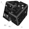
Figure 1 shows the general view of the electronic device with a three-dimensional transformable display (2x2x2 option, static mode), according to the invention; -
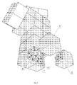
Figure 2 shows the general view of the electronic device with a three-dimensional transformable display (2x2x2 option, transformation (repositioning) mode), according to the invention; -
Figure 3 shows the general view of the electronic device with a three-dimensional transformable display (2x2x2 option) with a sectional cut showing the central element, according to the invention; -
Figure 4 shows the general view of one peripheral element of the electronic device, according to the invention; -
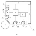
Figure 5 shows the functional scheme of one peripheral element of the electronic device, according to the invention; -
Figure 6 shows the sectional view of the connector of a peripheral element of the electronic device, according to the invention; -
Figure 7 shows the general view of a possible variant of implementation of the electronic device, according to the invention. - According to
Figs. 1-7 , the electronic device with a three-dimensional transformable display includes the central element (1) and several peripheral elements (2) located around it, which have flat faces (21) and are made so that they can move with respect to and rotate aboutcentral element 1. - Each
peripheral element 2 has at least one display (3) on the external face (211) of the element and contact groups (4) located on the internal faces (212) of this peripheral element. - Each
peripheral element 2 has its own microprocessor (5) connected to the own power supply (6). Microprocessor 5 andpower supply 6 are located insideperipheral element 2, andcontact groups 4 ofperipheral element 2 are formed bymagnets 41, which make it possible to hold adjacent peripheral elements together, while transmitting electric signals between the elements at the same time. - For example,
magnets 41 can act as four electric connectors, of which the first one is the grounding connector, the second is the +5 V voltage one, and the third and fourth are serial ports for data reception and transmission. In this example of the contact group implementation, connector options may differ, specifically, some of them can be magnetic, while the others, nonmagnetic. Data exchange connections can use different data protocols, not only serial ones. - In the general case, the number of contacts can be different.
-
Magnets 41 can be made as balls which are set inspherical seats 42 and can rotate about their centers. -
Figure 5 shows schematically the direction of the magnetic field (the arrow with letters N and S). It is seen that magnetic balls are oriented freely. As soon as such a magnetic ball is approached by another magnet installed in another peripheral element, the both balls turn inspherical seats 42 interacting with each other, and their opposite poles are attracted and hold individual elements together. Since the magnets are made of current-conducting materials, electric currents can run from one element to another. The formed electric circuit allows transmitting electric voltage and data between peripheral elements. - In the general case, the grounding connector can be connected to the central element without magnets or in direct connection.
- It should be emphasized that the magnet diameter is slightly less than the diameter of
spherical seats 42, i.e., the formed gap allowsmagnet 41 to move forward towards the matching element, which eliminates the problem of unstable gaps between peripheral elements. - In the general case,
spherical seats 42 can be replaced with special fixing elements, e.g.,collars 43, which let the magnet rotate freely, while fixing it on the peripheral element (seeFig. 6 ). - Generally, the device can have any shape, preferably that of a three-dimensional polyhedron, a typical representative of this class being a parallelepiped, preferably a cube. The device can consist of different amounts of peripheral elements.
- The main variants of the general form of the assembled device are as follows:
- 2x2x2 cube (eight peripheral elements);
- 3x3x3 cube (twenty-six peripheral elements);
- 4x4x4 cube (fifty-six peripheral elements);
- parallelepiped with different amounts of peripheral elements (2x2x3, 2x3x3, etc.);
- prisms having complicated shapes;
- polyhedrons with trapezoidal faces.
- Different variants can have different amounts of displays, since there can be variants, where all peripheral elements are identical, as in the 2x2x2 case, or, as in the 3x3x3 case, the peripheral elements are not identical, but are subdivided into corner elements (with three displays each) and side elements (with two displays). Correspondingly, such peripheral elements can have different amounts of internal faces.
- In the general case, peripheral elements can have additional electric components, including audio sources, microphones, and LEDs.
- The example of operation of the electronic device with a three-dimensional transformable, which is presented here, is exhaustive allowing for the fact, however, that it does not restrict possible application of the invention.
- A microprocessor and a power supply (rechargeable battery) are installed in each peripheral element and connected to displays on the external faces of the element. Thus, each peripheral element is an autonomous individual device. Being magnetically connected to similar peripheral elements via contact magnets, such elements are synchronized and can operate as an integral system, displaying a common image.
- Therefore, it is possible to assemble one integral electronic device, which can display either one common image on a set of individual displays, or several different individual images, for example, one image per element face.
- An important feature of such an electronic device is its mobility, i.e., the ability of individual peripheral elements to change their positions and be fixed in new positions with the general shape of the entire device being retained (in the general case, even the general shape can be transformed).
- When individual peripheral elements move, the magnets of the adjacent elements are detached and reconnected in new positions. Magnets and magnetic connectors hold the structure in a certain position, but also ensure transmission of voltages and interface signals between elements by creating an electric circuit for the interaction of peripheral elements.
- The central element installed in the center of the structure can be made as, e.g., a steel ball (in the general case, the shape and material of the central element can be different). It acts as an internal support for peripheral elements rotating about it.
- In the state, when an internal face of one peripheral element moves closely to a similar internal face of another peripheral element, the ball magnets affected by the magnetic field of the approaching contact group rotate and are attracted to each other according to their polarity (S N/N S), thus forming electric circuits. The situation, when identical poles of the ball magnets face each other (S S/N N), is impossible, since the balls are not fixed rigidly and can rotate in their seats.
- Magnets, which are fixed rigidly, and magnets, which can rotate freely, can be used simultaneously. In this case, fixed magnets can be used to ensure magnetic connection with the central ball.
- The electronic device with a three-dimensional transformable display can be implemented in practice by a specialist in the corresponding field and, being implemented, ensures realization of the stated purpose, which allows one to conclude that the "industrial applicability" criterion is complied with for this invention.
- In accordance with the proposed invention, a 2x2x2 prototype of the electronic device with a three-dimensional transformable display has been manufactured and has a central ball with eight identical peripheral elements surrounding it. Each of the peripheral elements has three displays.
- Tests of the prototype of the electronic device with a three-dimensional transformable display have showed that:
- it lets individual peripheral elements move easily;
- it ensures reliable mechanical connection of peripheral elements; and
- it ensures reliable electric connection of peripheral elements.
- Thus, this invention achieves the stated goal, namely, improvement of reliability and lifetime of the device.
- An additional useful technological result of the proposed invention is that it can be used:
- 1. as a new gaming space, which is attractive due to its novelty;
- 2. as a tool to develop spatial intelligence and cognitive skills of the gamer;
- 3. as a new digital desktop instrument that can display notifications about new e-mails, instant messages, information about currency rates, share prices, weather forecasts, movie times in local theaters, etc.
- 4. as a device that can display different information to different users (e.g., the situation, when a customer and a corporate employee are negotiating at the table and see opposite faces of the device).
- Additionally, this application discloses the following possible specifications of the device, which were added at the moment of submission of the international application and were not disclosed in the priority application, namely, an option of the invention, where magnets are covered with protective current-conducting plates made of a non-magnetic material, which act as contacts.
- Due to this advantageous option, there appears an alternative that lets a magnetic ball get oriented freely. In this case, the above-mentioned plate covers it on the outside and ensures high-quality connection by reducing the number of contacting surfaces in a pair from three (as in
Fig. 6 ) to one. The plate itself acts as a conductor, while the magnetic ball is but a self-orienting magnet. - There is a possible option to the invention, where protective current-conducting plates are made of brass.
- The choice of the specific material for manufacture of the current-conducting plate is determined by the above-specified advantageous characteristic.
- Another option of the invention is where the magnets on the inside of the peripheral element are limited by a ferromagnetic conductor connected to the peripheral element.
- Due to this advantageous option, a possibility appears that at the contact instant, the ferromagnetic conductor will be located at one of the poles of the magnetic ball. This point ensures the strongest magnetic attraction and, therefore, the best possible contact. This is one of the longest-lasting design options.
- Additionally, the description is supplemented with two new figures:
-
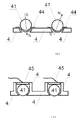
Figure 8 is a sectional drawing of the connector of a peripheral element of the electronic device for the option, where magnets are covered with protective current-conducting plates of non-magnetic materials that act as contacts, in accordance with the invention; and -
Figure 9 is a sectional drawing of the connector of a peripheral element of the electronic device for the option, where magnets on the inside of the peripheral elements are limited by a ferromagnetic conductor connected to the peripheral element, according to the invention. - The notations in the Figures are:
- 44 is the current-conducting plate of a non-magnetic material, and
- 45 is a ferromagnetic conductor.
- It is seen in
Fig. 8 that this option ensures the following advantage: it letsmagnetic ball 41 orient itself freely, whileplate 44 covers it on the outside, thus reducing the number of contact surfaces from three (as inFig. 6 ) to one and improving quality of the connection. The plate (44) itself acts as a conductor, andball 41 is required only as a self-orienting magnet. -
Figure 9 shows thatferromagnetic conductor 45 is located on the side opposite toball 41. An advantage of this option is that at the instant of the contact,ferromagnetic conductor 45 will be located at one of the poles ofmagnetic ball 41. At this point, the strongest magnetic attraction and, therefore, the best possible contact are ensured. - The options in
Fig. 8 and Fig. 9 are better from the viewpoint of their consumer performance, as compared to the option shown inFig. 6 . The option inFig. 8 has a better quality of the electric contact, and the option inFig. 9 has a longer lifetime due to the fact thatplate 44 is subject to wearing.
Claims (7)
- An electronic device with a three-dimensional transformable display, which includes one central element, around which several peripheral elements are located, each having flat faces and being movable with respect to, and rotatable about, the central element, and each peripheral element having at least one display on an external face of that peripheral element, and contact groups on internal faces of the peripheral element, the electronic device characterized in that: each peripheral element has its own microprocessor connected to its own power supply, and the microprocessor and the power supply are installed inside the peripheral element, wherein the contact groups in the peripheral element are formed from magnets, which are manufactured in such a way as to ensure the possibility of holding adjacent peripheral elements together, while transmitting simultaneously electrical signals there between.
- The electronic device according to claim 1, characterized in that: the magnets are made as balls installed in seats and capable of rotating about their centers.
- The electronic device according to claim 1, characterized in that: the seats are spherical.
- The electronic device according to claim 2, characterized in that: the magnets are fixed on the contact groups with collars that hold the magnets, capable of rotating about their centers, in place.
- The electronic device according to claim 2, characterized in that: the magnets are covered with protective current-conducting plates of a non-magnetic material, which act as contacts.
- The electronic device according to claim 5, characterized in that: the protective current-conducting plates are made of brass.
- The electronic device according to claim 2, characterized in that: the magnets on the internal side of the peripheral element are limited by a ferromagnetic conductor connected with a peripheral element.
Applications Claiming Priority (2)
| Application Number | Priority Date | Filing Date | Title |
|---|---|---|---|
| RU2017106039A RU2644313C1 (en) | 2017-02-23 | 2017-02-23 | Electronic device with volumetric transformable display |
| PCT/RU2018/050016 WO2018156055A1 (en) | 2017-02-23 | 2018-02-15 | Electronic device with a three-dimensional transformable display |
Publications (3)
| Publication Number | Publication Date |
|---|---|
| EP3586935A1 true EP3586935A1 (en) | 2020-01-01 |
| EP3586935A4 EP3586935A4 (en) | 2021-01-20 |
| EP3586935B1 EP3586935B1 (en) | 2025-08-20 |
Family
ID=61173824
Family Applications (1)
| Application Number | Title | Priority Date | Filing Date |
|---|---|---|---|
| EP18756842.3A Active EP3586935B1 (en) | 2017-02-23 | 2018-02-15 | Electronic device with a three-dimensional transformable display |
Country Status (9)
| Country | Link |
|---|---|
| EP (1) | EP3586935B1 (en) |
| JP (2) | JP6942382B2 (en) |
| KR (2) | KR102339889B1 (en) |
| CN (1) | CN108712923B (en) |
| AU (2) | AU2018225026B2 (en) |
| CA (1) | CA3092094A1 (en) |
| ES (1) | ES3047687T3 (en) |
| RU (1) | RU2644313C1 (en) |
| WO (1) | WO2018156055A1 (en) |
Cited By (1)
| Publication number | Priority date | Publication date | Assignee | Title |
|---|---|---|---|---|
| US12691375B2 (en) | 2023-08-01 | 2026-07-28 | Nintendo Co., Ltd. | Game controller |
Families Citing this family (8)
| Publication number | Priority date | Publication date | Assignee | Title |
|---|---|---|---|---|
| RU2720884C1 (en) * | 2019-07-09 | 2020-05-13 | Кубиос Инк. | Electrical connector and electrical connection |
| RU194656U1 (en) * | 2019-07-24 | 2019-12-18 | Хуэйчжи Цзян | CUBE PUZZLE |
| RU2723664C1 (en) * | 2020-01-06 | 2020-06-17 | Илья Викторович Осипов | Electronic device with volumetric transformable display (versions) |
| US20220118354A1 (en) * | 2020-10-21 | 2022-04-21 | IIya V. Osipov | 3-D Puzzle with moving sectors |
| EP4094814A1 (en) * | 2021-05-26 | 2022-11-30 | Guangzhou Ganyuan Intelligent Technology Co., Ltd. | Magnetic levitation magic cube |
| RU2762371C1 (en) * | 2021-06-01 | 2021-12-20 | Илья Викторович Осипов | Volumetric magnetic puzzle with mobile sectors |
| CN113318423B (en) * | 2021-06-15 | 2024-03-22 | 浙江大学台州研究院 | Wen creates magic cube that benefits intelligence |
| CN121443362A (en) * | 2023-08-01 | 2026-01-30 | 任天堂株式会社 | Game consoles and game systems |
Family Cites Families (23)
| Publication number | Priority date | Publication date | Assignee | Title |
|---|---|---|---|---|
| US3655201A (en) * | 1970-03-04 | 1972-04-11 | Moleculon Res Corp | Pattern forming puzzle and method with pieces rotatable in groups |
| SU1697863A1 (en) * | 1989-03-30 | 1991-12-15 | Самарское Производственное Объединение "Завод Им.Масленникова" | Volumetric puzzle-game |
| JPH07101647B2 (en) * | 1993-04-12 | 1995-11-01 | 株式会社マグエックス | Adsorbent |
| ITMI20040822A1 (en) * | 2004-04-27 | 2004-07-27 | Vincentelli Claudio | SYSTEM OF MODULAR BLOCKS WITH MAGNETIC CONNECTION FRAME |
| NZ536138A (en) * | 2004-10-22 | 2007-06-29 | Mark Stolten | A three-dimensional puzzle having magnetic interactions between a core and plural pieces |
| WO2007046056A2 (en) * | 2005-10-20 | 2007-04-26 | Koninklijke Philips Electronics N.V. | Game with programmable light emitting segments |
| WO2008046126A1 (en) * | 2006-10-18 | 2008-04-24 | Steven Titmuss | Puzzle apparatus |
| US8087671B2 (en) * | 2008-12-03 | 2012-01-03 | Pantazis Constantine Houlis | Spatial puzzle apparatus |
| CN104115335A (en) * | 2009-02-02 | 2014-10-22 | 艾派克斯技术股份有限公司 | Flexible magnetic interconnects |
| RU2403946C1 (en) * | 2009-03-16 | 2010-11-20 | Кирилл Владимирович Дьяковский | Volume brainteaser |
| GB2478591A (en) * | 2010-03-12 | 2011-09-14 | Gideon Cube-Sherman | Articulated sub-units |
| US8465356B2 (en) * | 2010-11-22 | 2013-06-18 | Gonzalez Rosendo | Display puzzle |
| US20120258436A1 (en) * | 2011-04-08 | 2012-10-11 | Case Western Reserve University | Automated assessment of cognitive, fine-motor, and memory skills |
| WO2013066901A1 (en) * | 2011-10-31 | 2013-05-10 | Modular Robotics Incorporated | Modular kinematic construction kit |
| TWI465670B (en) * | 2012-05-17 | 2014-12-21 | Lattice Energy Technology Corp | Illuminable building block |
| EP2800020B1 (en) * | 2013-04-30 | 2020-11-04 | Dassault Systèmes | A computer-implemented method for manipulating three-dimensional modeled objects of an assembly in a three-dimensional scene. |
| KR20160083948A (en) * | 2013-11-13 | 2016-07-12 | 나노포트 테크놀로지 인크. | Magnetic connectors |
| CN203634799U (en) * | 2013-11-20 | 2014-06-11 | 安徽省科普产品工程研究中心有限责任公司 | Electronic magic cube |
| RU2556489C2 (en) * | 2014-05-07 | 2015-07-10 | Сергей Владимирович Мурашев | Board game - puzzles |
| JP2017116893A (en) * | 2015-12-26 | 2017-06-29 | 株式会社村田製作所 | Stereo image display device |
| CN106110651B (en) * | 2016-08-12 | 2017-11-21 | 佛山市计客创新科技有限公司 | Intelligent magic cube and its sensing axle centre structure, the clocking method used |
| WO2018075714A1 (en) * | 2016-10-20 | 2018-04-26 | Osipov Ilya | Electrical connector |
| CN107665080B (en) * | 2017-09-27 | 2021-04-13 | 北京小米移动软件有限公司 | Information processing method and intelligent Rubik's cube |
-
2017
- 2017-02-23 RU RU2017106039A patent/RU2644313C1/en active
-
2018
- 2018-02-15 CN CN201880000510.5A patent/CN108712923B/en active Active
- 2018-02-15 AU AU2018225026A patent/AU2018225026B2/en not_active Ceased
- 2018-02-15 JP JP2019567222A patent/JP6942382B2/en active Active
- 2018-02-15 KR KR1020197024861A patent/KR102339889B1/en active Active
- 2018-02-15 WO PCT/RU2018/050016 patent/WO2018156055A1/en not_active Ceased
- 2018-02-15 EP EP18756842.3A patent/EP3586935B1/en active Active
- 2018-02-15 CA CA3092094A patent/CA3092094A1/en not_active Abandoned
- 2018-02-15 ES ES18756842T patent/ES3047687T3/en active Active
- 2018-02-15 KR KR1020217040485A patent/KR102385609B1/en active Active
-
2021
- 2021-09-01 JP JP2021142554A patent/JP7105513B2/en active Active
- 2021-10-28 AU AU2021257999A patent/AU2021257999A1/en not_active Abandoned
Cited By (1)
| Publication number | Priority date | Publication date | Assignee | Title |
|---|---|---|---|---|
| US12691375B2 (en) | 2023-08-01 | 2026-07-28 | Nintendo Co., Ltd. | Game controller |
Also Published As
| Publication number | Publication date |
|---|---|
| KR20190109488A (en) | 2019-09-25 |
| JP2022003391A (en) | 2022-01-11 |
| CA3092094A1 (en) | 2018-08-30 |
| EP3586935A4 (en) | 2021-01-20 |
| KR102385609B1 (en) | 2022-04-12 |
| JP7105513B2 (en) | 2022-07-25 |
| JP2020514009A (en) | 2020-05-21 |
| KR20210156842A (en) | 2021-12-27 |
| CN108712923B (en) | 2021-10-15 |
| RU2644313C1 (en) | 2018-02-08 |
| AU2018225026A1 (en) | 2019-10-17 |
| WO2018156055A1 (en) | 2018-08-30 |
| ES3047687T3 (en) | 2025-12-04 |
| AU2018225026B2 (en) | 2021-08-05 |
| KR102339889B1 (en) | 2021-12-16 |
| JP6942382B2 (en) | 2021-09-29 |
| EP3586935B1 (en) | 2025-08-20 |
| AU2021257999A1 (en) | 2021-11-25 |
| CN108712923A (en) | 2018-10-26 |
Similar Documents
| Publication | Publication Date | Title |
|---|---|---|
| EP3586935B1 (en) | Electronic device with a three-dimensional transformable display | |
| US11819767B2 (en) | Electronic device with a transformable multi-planar segmented display | |
| KR102280400B1 (en) | electrical connector | |
| US11510324B2 (en) | Electronic device with a volumetric transformable display | |
| CN105723566A (en) | Magnetic connectors | |
| HK40021174A (en) | Electronic device with a three-dimensional transformable display | |
| HK40021174B (en) | Electronic device with a three-dimensional transformable display | |
| HK1262768A1 (en) | Electronic device with a three-dimensional transformable display | |
| JP2010113956A (en) | Connector | |
| HK40004731A (en) | Electrical connector | |
| HK40004731B (en) | Electrical connector |
Legal Events
| Date | Code | Title | Description |
|---|---|---|---|
| STAA | Information on the status of an ep patent application or granted ep patent |
Free format text: STATUS: THE INTERNATIONAL PUBLICATION HAS BEEN MADE |
|
| PUAI | Public reference made under article 153(3) epc to a published international application that has entered the european phase |
Free format text: ORIGINAL CODE: 0009012 |
|
| STAA | Information on the status of an ep patent application or granted ep patent |
Free format text: STATUS: REQUEST FOR EXAMINATION WAS MADE |
|
| 17P | Request for examination filed |
Effective date: 20190918 |
|
| AK | Designated contracting states |
Kind code of ref document: A1 Designated state(s): AL AT BE BG CH CY CZ DE DK EE ES FI FR GB GR HR HU IE IS IT LI LT LU LV MC MK MT NL NO PL PT RO RS SE SI SK SM TR |
|
| AX | Request for extension of the european patent |
Extension state: BA ME |
|
| DAV | Request for validation of the european patent (deleted) | ||
| DAX | Request for extension of the european patent (deleted) | ||
| REG | Reference to a national code |
Ref country code: HK Ref legal event code: DE Ref document number: 40021174 Country of ref document: HK |
|
| A4 | Supplementary search report drawn up and despatched |
Effective date: 20201217 |
|
| RIC1 | Information provided on ipc code assigned before grant |
Ipc: H04B 5/00 20060101ALI20201211BHEP Ipc: A63F 13/90 20140101ALI20201211BHEP Ipc: H01R 13/22 20060101ALI20201211BHEP Ipc: H01R 13/62 20060101ALI20201211BHEP Ipc: A63H 33/04 20060101ALI20201211BHEP Ipc: A63F 9/08 20060101AFI20201211BHEP Ipc: A63F 13/92 20140101ALI20201211BHEP Ipc: G06F 1/16 20060101ALI20201211BHEP Ipc: H01R 11/30 20060101ALI20201211BHEP |
|
| GRAP | Despatch of communication of intention to grant a patent |
Free format text: ORIGINAL CODE: EPIDOSNIGR1 |
|
| STAA | Information on the status of an ep patent application or granted ep patent |
Free format text: STATUS: GRANT OF PATENT IS INTENDED |
|
| INTG | Intention to grant announced |
Effective date: 20250515 |
|
| GRAS | Grant fee paid |
Free format text: ORIGINAL CODE: EPIDOSNIGR3 |
|
| GRAA | (expected) grant |
Free format text: ORIGINAL CODE: 0009210 |
|
| STAA | Information on the status of an ep patent application or granted ep patent |
Free format text: STATUS: THE PATENT HAS BEEN GRANTED |
|
| AK | Designated contracting states |
Kind code of ref document: B1 Designated state(s): AL AT BE BG CH CY CZ DE DK EE ES FI FR GB GR HR HU IE IS IT LI LT LU LV MC MK MT NL NO PL PT RO RS SE SI SK SM TR |
|
| REG | Reference to a national code |
Ref country code: GB Ref legal event code: FG4D |
|
| RIN1 | Information on inventor provided before grant (corrected) |
Inventor name: OSIPOV, ILYA VIKTOROVICH |
|
| REG | Reference to a national code |
Ref country code: CH Ref legal event code: EP |
|
| REG | Reference to a national code |
Ref country code: IE Ref legal event code: FG4D |
|
| REG | Reference to a national code |
Ref country code: DE Ref legal event code: R096 Ref document number: 602018084765 Country of ref document: DE |
|
| REG | Reference to a national code |
Ref country code: ES Ref legal event code: FG2A Ref document number: 3047687 Country of ref document: ES Kind code of ref document: T3 Effective date: 20251204 |
|
| REG | Reference to a national code |
Ref country code: NL Ref legal event code: MP Effective date: 20250820 |
|
| PG25 | Lapsed in a contracting state [announced via postgrant information from national office to epo] |
Ref country code: IS Free format text: LAPSE BECAUSE OF FAILURE TO SUBMIT A TRANSLATION OF THE DESCRIPTION OR TO PAY THE FEE WITHIN THE PRESCRIBED TIME-LIMIT Effective date: 20251220 |
|
| PGFP | Annual fee paid to national office [announced via postgrant information from national office to epo] |
Ref country code: GB Payment date: 20251205 Year of fee payment: 9 |
|
| PG25 | Lapsed in a contracting state [announced via postgrant information from national office to epo] |
Ref country code: NO Free format text: LAPSE BECAUSE OF FAILURE TO SUBMIT A TRANSLATION OF THE DESCRIPTION OR TO PAY THE FEE WITHIN THE PRESCRIBED TIME-LIMIT Effective date: 20251120 |
|
| REG | Reference to a national code |
Ref country code: LT Ref legal event code: MG9D |
|
| PG25 | Lapsed in a contracting state [announced via postgrant information from national office to epo] |
Ref country code: PT Free format text: LAPSE BECAUSE OF FAILURE TO SUBMIT A TRANSLATION OF THE DESCRIPTION OR TO PAY THE FEE WITHIN THE PRESCRIBED TIME-LIMIT Effective date: 20251222 |
|
| PG25 | Lapsed in a contracting state [announced via postgrant information from national office to epo] |
Ref country code: FI Free format text: LAPSE BECAUSE OF FAILURE TO SUBMIT A TRANSLATION OF THE DESCRIPTION OR TO PAY THE FEE WITHIN THE PRESCRIBED TIME-LIMIT Effective date: 20250820 |
|
| PG25 | Lapsed in a contracting state [announced via postgrant information from national office to epo] |
Ref country code: NL Free format text: LAPSE BECAUSE OF FAILURE TO SUBMIT A TRANSLATION OF THE DESCRIPTION OR TO PAY THE FEE WITHIN THE PRESCRIBED TIME-LIMIT Effective date: 20250820 Ref country code: HR Free format text: LAPSE BECAUSE OF FAILURE TO SUBMIT A TRANSLATION OF THE DESCRIPTION OR TO PAY THE FEE WITHIN THE PRESCRIBED TIME-LIMIT Effective date: 20250820 |
|
| PGFP | Annual fee paid to national office [announced via postgrant information from national office to epo] |
Ref country code: FR Payment date: 20251202 Year of fee payment: 9 |
|
| PG25 | Lapsed in a contracting state [announced via postgrant information from national office to epo] |
Ref country code: GR Free format text: LAPSE BECAUSE OF FAILURE TO SUBMIT A TRANSLATION OF THE DESCRIPTION OR TO PAY THE FEE WITHIN THE PRESCRIBED TIME-LIMIT Effective date: 20251121 |
|
| PG25 | Lapsed in a contracting state [announced via postgrant information from national office to epo] |
Ref country code: SE Free format text: LAPSE BECAUSE OF FAILURE TO SUBMIT A TRANSLATION OF THE DESCRIPTION OR TO PAY THE FEE WITHIN THE PRESCRIBED TIME-LIMIT Effective date: 20250820 |
|
| PG25 | Lapsed in a contracting state [announced via postgrant information from national office to epo] |
Ref country code: LV Free format text: LAPSE BECAUSE OF FAILURE TO SUBMIT A TRANSLATION OF THE DESCRIPTION OR TO PAY THE FEE WITHIN THE PRESCRIBED TIME-LIMIT Effective date: 20250820 |
|
| PG25 | Lapsed in a contracting state [announced via postgrant information from national office to epo] |
Ref country code: BG Free format text: LAPSE BECAUSE OF FAILURE TO SUBMIT A TRANSLATION OF THE DESCRIPTION OR TO PAY THE FEE WITHIN THE PRESCRIBED TIME-LIMIT Effective date: 20250820 Ref country code: PL Free format text: LAPSE BECAUSE OF FAILURE TO SUBMIT A TRANSLATION OF THE DESCRIPTION OR TO PAY THE FEE WITHIN THE PRESCRIBED TIME-LIMIT Effective date: 20250820 |
|
| PG25 | Lapsed in a contracting state [announced via postgrant information from national office to epo] |
Ref country code: RS Free format text: LAPSE BECAUSE OF FAILURE TO SUBMIT A TRANSLATION OF THE DESCRIPTION OR TO PAY THE FEE WITHIN THE PRESCRIBED TIME-LIMIT Effective date: 20251120 |
|
| REG | Reference to a national code |
Ref country code: AT Ref legal event code: MK05 Ref document number: 1826721 Country of ref document: AT Kind code of ref document: T Effective date: 20250820 |
|
| PG25 | Lapsed in a contracting state [announced via postgrant information from national office to epo] |
Ref country code: SM Free format text: LAPSE BECAUSE OF FAILURE TO SUBMIT A TRANSLATION OF THE DESCRIPTION OR TO PAY THE FEE WITHIN THE PRESCRIBED TIME-LIMIT Effective date: 20250820 |
|
| PGFP | Annual fee paid to national office [announced via postgrant information from national office to epo] |
Ref country code: ES Payment date: 20260302 Year of fee payment: 9 |
|
| PG25 | Lapsed in a contracting state [announced via postgrant information from national office to epo] |
Ref country code: DK Free format text: LAPSE BECAUSE OF FAILURE TO SUBMIT A TRANSLATION OF THE DESCRIPTION OR TO PAY THE FEE WITHIN THE PRESCRIBED TIME-LIMIT Effective date: 20250820 |
|
| PGFP | Annual fee paid to national office [announced via postgrant information from national office to epo] |
Ref country code: DE Payment date: 20251203 Year of fee payment: 9 |
|
| PG25 | Lapsed in a contracting state [announced via postgrant information from national office to epo] |
Ref country code: AT Free format text: LAPSE BECAUSE OF FAILURE TO SUBMIT A TRANSLATION OF THE DESCRIPTION OR TO PAY THE FEE WITHIN THE PRESCRIBED TIME-LIMIT Effective date: 20250820 |
|
| PGFP | Annual fee paid to national office [announced via postgrant information from national office to epo] |
Ref country code: IT Payment date: 20251203 Year of fee payment: 9 |
|
| PG25 | Lapsed in a contracting state [announced via postgrant information from national office to epo] |
Ref country code: CZ Free format text: LAPSE BECAUSE OF FAILURE TO SUBMIT A TRANSLATION OF THE DESCRIPTION OR TO PAY THE FEE WITHIN THE PRESCRIBED TIME-LIMIT Effective date: 20250820 |
|
| PG25 | Lapsed in a contracting state [announced via postgrant information from national office to epo] |
Ref country code: EE Free format text: LAPSE BECAUSE OF FAILURE TO SUBMIT A TRANSLATION OF THE DESCRIPTION OR TO PAY THE FEE WITHIN THE PRESCRIBED TIME-LIMIT Effective date: 20250820 Ref country code: SK Free format text: LAPSE BECAUSE OF FAILURE TO SUBMIT A TRANSLATION OF THE DESCRIPTION OR TO PAY THE FEE WITHIN THE PRESCRIBED TIME-LIMIT Effective date: 20250820 |
|
| REG | Reference to a national code |
Ref country code: DE Ref legal event code: R097 Ref document number: 602018084765 Country of ref document: DE |
|
| PLBE | No opposition filed within time limit |
Free format text: ORIGINAL CODE: 0009261 |
|
| STAA | Information on the status of an ep patent application or granted ep patent |
Free format text: STATUS: NO OPPOSITION FILED WITHIN TIME LIMIT |
|
| PG25 | Lapsed in a contracting state [announced via postgrant information from national office to epo] |
Ref country code: LT Free format text: LAPSE BECAUSE OF FAILURE TO SUBMIT A TRANSLATION OF THE DESCRIPTION OR TO PAY THE FEE WITHIN THE PRESCRIBED TIME-LIMIT Effective date: 20250820 |
|
| REG | Reference to a national code |
Ref country code: CH Ref legal event code: L10 Free format text: ST27 STATUS EVENT CODE: U-0-0-L10-L00 (AS PROVIDED BY THE NATIONAL OFFICE) Effective date: 20260701 |
|
| 26N | No opposition filed |
Effective date: 20260521 |