EP3586776A1 - Medical instrument for percutaneous release procedures - Google Patents
Medical instrument for percutaneous release procedures Download PDFInfo
- Publication number
- EP3586776A1 EP3586776A1 EP18206119.2A EP18206119A EP3586776A1 EP 3586776 A1 EP3586776 A1 EP 3586776A1 EP 18206119 A EP18206119 A EP 18206119A EP 3586776 A1 EP3586776 A1 EP 3586776A1
- Authority
- EP
- European Patent Office
- Prior art keywords
- medical instrument
- rod member
- elongated rod
- bevelled
- resp
- Prior art date
- Legal status (The legal status is an assumption and is not a legal conclusion. Google has not performed a legal analysis and makes no representation as to the accuracy of the status listed.)
- Withdrawn
Links
- 238000000034 method Methods 0.000 title claims abstract description 25
- 238000005520 cutting process Methods 0.000 claims abstract description 34
- 210000003141 lower extremity Anatomy 0.000 claims abstract description 8
- 210000001364 upper extremity Anatomy 0.000 claims abstract description 8
- 230000001747 exhibiting effect Effects 0.000 claims abstract description 4
- 238000004049 embossing Methods 0.000 claims description 7
- 210000003414 extremity Anatomy 0.000 claims description 5
- 238000010330 laser marking Methods 0.000 claims description 4
- 239000007787 solid Substances 0.000 claims description 4
- 210000001519 tissue Anatomy 0.000 description 13
- 208000003295 carpal tunnel syndrome Diseases 0.000 description 5
- 208000011580 syndromic disease Diseases 0.000 description 5
- 238000001356 surgical procedure Methods 0.000 description 4
- 238000003780 insertion Methods 0.000 description 3
- 230000037431 insertion Effects 0.000 description 3
- 239000000523 sample Substances 0.000 description 3
- 238000004026 adhesive bonding Methods 0.000 description 2
- 238000002592 echocardiography Methods 0.000 description 2
- 230000003902 lesion Effects 0.000 description 2
- 210000004872 soft tissue Anatomy 0.000 description 2
- 230000000007 visual effect Effects 0.000 description 2
- 208000002472 Morton Neuroma Diseases 0.000 description 1
- 230000003444 anaesthetic effect Effects 0.000 description 1
- 230000000740 bleeding effect Effects 0.000 description 1
- 210000004204 blood vessel Anatomy 0.000 description 1
- 238000010276 construction Methods 0.000 description 1
- 230000001419 dependent effect Effects 0.000 description 1
- 238000009826 distribution Methods 0.000 description 1
- 230000000694 effects Effects 0.000 description 1
- 238000003384 imaging method Methods 0.000 description 1
- 238000001802 infusion Methods 0.000 description 1
- 238000001990 intravenous administration Methods 0.000 description 1
- 238000002324 minimally invasive surgery Methods 0.000 description 1
- 238000012986 modification Methods 0.000 description 1
- 230000004048 modification Effects 0.000 description 1
- 230000035515 penetration Effects 0.000 description 1
- 231100000241 scar Toxicity 0.000 description 1
- 239000012815 thermoplastic material Substances 0.000 description 1
- 238000011144 upstream manufacturing Methods 0.000 description 1
Images


Classifications
-
- A—HUMAN NECESSITIES
- A61—MEDICAL OR VETERINARY SCIENCE; HYGIENE
- A61B—DIAGNOSIS; SURGERY; IDENTIFICATION
- A61B17/00—Surgical instruments, devices or methods, e.g. tourniquets
- A61B17/32—Surgical cutting instruments
- A61B17/320016—Endoscopic cutting instruments, e.g. arthroscopes, resectoscopes
- A61B17/320036—Endoscopic cutting instruments, e.g. arthroscopes, resectoscopes adapted for use within the carpal tunnel
-
- A—HUMAN NECESSITIES
- A61—MEDICAL OR VETERINARY SCIENCE; HYGIENE
- A61B—DIAGNOSIS; SURGERY; IDENTIFICATION
- A61B17/00—Surgical instruments, devices or methods, e.g. tourniquets
- A61B17/00234—Surgical instruments, devices or methods, e.g. tourniquets for minimally invasive surgery
- A61B2017/00292—Surgical instruments, devices or methods, e.g. tourniquets for minimally invasive surgery mounted on or guided by flexible, e.g. catheter-like, means
- A61B2017/003—Steerable
- A61B2017/00305—Constructional details of the flexible means
- A61B2017/00314—Separate linked members
-
- A—HUMAN NECESSITIES
- A61—MEDICAL OR VETERINARY SCIENCE; HYGIENE
- A61B—DIAGNOSIS; SURGERY; IDENTIFICATION
- A61B17/00—Surgical instruments, devices or methods, e.g. tourniquets
- A61B2017/0042—Surgical instruments, devices or methods, e.g. tourniquets with special provisions for gripping
- A61B2017/00455—Orientation indicators, e.g. recess on the handle
-
- A—HUMAN NECESSITIES
- A61—MEDICAL OR VETERINARY SCIENCE; HYGIENE
- A61B—DIAGNOSIS; SURGERY; IDENTIFICATION
- A61B90/00—Instruments, implements or accessories specially adapted for surgery or diagnosis and not covered by any of the groups A61B1/00 - A61B50/00, e.g. for luxation treatment or for protecting wound edges
- A61B90/08—Accessories or related features not otherwise provided for
- A61B2090/0801—Prevention of accidental cutting or pricking
- A61B2090/08021—Prevention of accidental cutting or pricking of the patient or his organs
-
- A—HUMAN NECESSITIES
- A61—MEDICAL OR VETERINARY SCIENCE; HYGIENE
- A61B—DIAGNOSIS; SURGERY; IDENTIFICATION
- A61B90/00—Instruments, implements or accessories specially adapted for surgery or diagnosis and not covered by any of the groups A61B1/00 - A61B50/00, e.g. for luxation treatment or for protecting wound edges
- A61B90/39—Markers, e.g. radio-opaque or breast lesions markers
- A61B2090/3925—Markers, e.g. radio-opaque or breast lesions markers ultrasonic
-
- A—HUMAN NECESSITIES
- A61—MEDICAL OR VETERINARY SCIENCE; HYGIENE
- A61B—DIAGNOSIS; SURGERY; IDENTIFICATION
- A61B90/00—Instruments, implements or accessories specially adapted for surgery or diagnosis and not covered by any of the groups A61B1/00 - A61B50/00, e.g. for luxation treatment or for protecting wound edges
- A61B90/39—Markers, e.g. radio-opaque or breast lesions markers
- A61B2090/3937—Visible markers
Definitions
- the present invention generally relates to a medical instrument for percutaneous release procedures, especially percutaneous release procedures on upper or lower limbs, such as but not limited to percutaneous carpal tunnel release or percutaneous A1 pulley release.
- Carpal tunnel syndrome (CTS) and trigger finger syndrome (TFS) can conveniently be treated by percutaneous release procedures. These minimally invasive procedures are typically carried out using simple puncture needles or more complex hook knives or push knives. Such medical instruments are also used for other minimally invasive release procedures on upper or lower limbs, such as for the treatment of Morton's neuroma, tarsal tunnel release, de Quervain syndrome, epicondylalgy, shoulder surgery, and similar release procedures.
- a general aim of the invention is to provide an improved medical instrument for percutaneous release procedures, especially percutaneous release procedures on upper or lower limbs, such as percutaneous carpal tunnel release or percutaneous A1 pulley release, as well as other percutaneous release procedures used in the treatment of the conditions or syndromes listed in the background of the present invention.
- a medical instrument for percutaneous release procedures comprising a handle portion designed to allow handling, orientation and manipulation of the medical instrument by a surgeon and an elongated rod member secured to the handle portion and extending substantially within a defined plane.
- a first portion of the elongated rod member extends substantially along a first direction within the defined plane away from the handle portion, and a second portion of the elongated rod member, downstream of the first portion, is curved and/or bent within the defined plane.
- a free end of the elongated rod member, at a terminal end of the second portion, is shaped as a bevelled end exhibiting a bevelled surface, which bevelled end is designed to act as a cutting device to severe tissue, said bevelled surface being inclined with respect to the defined plane.
- an angle of inclination of a plane comprising the bevelled surface with respect to the defined plane is of the order of 10° to 40°. Even more preferably, the angle of inclination is of the order of 15° to 30°.
- an end section of the elongated rod member extends substantially perpendicularly to the first direction.
- the end section of the elongated rod member may in particular extend along a second direction that forms an angle with respect to the first direction that is comprised between 80° and 120°.
- the first portion of the elongated rod member is a substantially rectilinear section.
- the second portion includes at least one curved section extending over an angle that exceeds 30°.
- the second portion includes a single curved section extending over an angle that exceeds 60° and a radius of curvature of the curved section is preferably of the order of 30 to 45 mm.
- an end section of the elongated rod member, at the terminal end of the second portion may in particular extend along a second direction perpendicularly to the first direction.
- the second portion includes multiple, especially three, curved sections each extending over an angle that does not exceed 40°.
- the multiple curved sections may in particular be separated by substantially rectilinear sections having a length of the order of 15 to 25 mm.
- the elongated rod member is provided with a plurality of markings, such as embossings, designed to be distinguishable under sonography. These markings are preferably distributed over the second portion of the elongated rod member.
- the bevelled end exhibits at least two bevelled surfaces with distinct angles of inclination.
- the at least two bevelled surfaces facilitate location and orientation of the terminal end of the medical instrument under sonography as the bevelled surfaces will generate different sonographic echoes or signatures due to the distinct angles of inclination.
- a leading edge of the bevelled end, at a distal extremity of the bevelled end, is provided with at least one side bevel defining a cutting edge.
- the handle portion of the medical instrument may be provided with a visible marking, such as a laser marking, which visible marking is preferably provided on an inner face of the handle portion which is oriented in a same direction as the second portion of the elongated rod member.
- a visible marking such as a laser marking
- a cross-sectional area of the elongated rod member does not exceed 5 mm 2 .
- a diameter of the elongated rod member may in particular be of the order of 1 to 2 mm.
- the elongated rod member has a substantially circular cross-section.
- the elongated rod member may furthermore be solid and non-hollow.
- the medical instrument of the invention is used for the purpose of performing percutaneous release procedures, the percutaneous release procedures being performed under the assistance of a sonography.
- the medical instrument may in particular be a medical instrument in accordance with claim 8 or 9, the plurality of markings or the at least two bevelled surfaces being exploited for the purpose of orienting the medical instrument during the percutaneous release procedures.
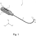
- FIG. 1 there is shown a first embodiment of a medical instrument, designated by reference numeral 1, in accordance with the present invention, which first embodiment is particularly suited for percutaneous carpal tunnel release in the treatment of the carpal tunnel syndrome (CTS).
- CTS carpal tunnel syndrome
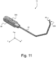
- FIG. 11 to 20 there is shown another embodiment of a medical instrument, designated by reference numeral 10, in accordance with the present invention, which other embodiment is particularly suited for percutaneous A1 pulley release in the treatment of the trigger finger syndrome (TFS).
- a variant of this second embodiment, designated by reference numeral 10*, is further shown in Figures 28 to 31 .
- a handle portion 2, resp. 20, designed to allow handling, orientation and manipulation of the medical instrument by a surgeon and an elongated rod member 5, 50, 5*, resp. 50*, secured to the handle portion 2, resp. 20, and extending substantially within a defined plane, designated by reference P0.
- this defined plane P0 is assumed to be a vertical plane parallel to the vertical plane formed by the y and z axes.
- a first portion of the elongated rod member 5, 50, 5*, resp. 50* extends substantially along a first direction a1, resp. a1', within the defined plane P0 away from the handle portion 2, resp. 20, namely parallel to the y axis.
- This first portion can especially be a substantially rectilinear section.
- a second portion of the elongated rod member 5, 50, 5*, resp. 50*, downstream of the first portion is curved and/or bent within the defined plane P0.
- 50A*, of the second portion is shaped as a bevelled end 6, 60, 6*, resp. 60*, exhibiting a bevelled surface 6A (see Figures 5 and 6 ), 60A (see Figures 14 to 16 ), 6A* (see Figures 25 to 27 ), resp. 60A* (see Figures 29 to 31 ).
- This bevelled end 6, 60, 6*, resp. 60* is designed to act as a cutting device to severe tissue, the bevelled surface 6A,.60A, 6A*, resp. 60A*, being inclined with respect to the defined plane P0.
- the angle of inclination ⁇ 1, ⁇ 2, ⁇ 1*, resp. ⁇ 2*, of a plane P, P', P*, resp. P**, comprising the bevelled surface 6A (see Figure 6 ), 60A (see Figure 16 ), 6A* (see Figure 27 ), resp. 60A* (see Figure 31 ) with respect to the defined plane P0 is of the order of 10° to 40°, even more preferably of the order of 15° to 30°.
- angles of inclination ⁇ 1, ⁇ 2 and ⁇ 2* are each of the order of 30°
- angle of inclination ⁇ 1* is of the order of 15°.
- Figures 21A-B and 22A-D show a configuration of a bevelled end 600, at a terminal end 500A of an elongated rod member 500 of a medical instrument in accordance with another embodiment of the present invention. This configuration is especially applicable in the context of the aforementioned medical instruments as shown in Figures 1 to 20 .
- the bevelled end 600 shown in Figures 21A-B and 22A-D exhibits at least two bevelled surfaces 600A, 610A having distinct angles of inclination ⁇ 3 and ⁇ 4 with respect to the defined plane P0 (references P" and P"' here designating the relevant planes comprising the bevelled surfaces 600A, 610A, respectively).
- This configuration is particularly advantageous for the purpose of locating and orienting the terminal end 500A of the medical instrument under sonography as the bevelled surfaces 600A, 610A will generate different sonographic echoes or signatures due to the distinct angles of inclination ⁇ 3, ⁇ 4.
- the angle of inclination ⁇ 3 of the plane P" comprising the bevelled surface 600A with respect to the defined plane P0 is of the order of 15° and the angle of inclination ⁇ 4 of the plane P"' comprising the bevelled surface 610A with respect to the defined plane P0 is of the order of 30°.
- Figures 21A-B and 22A-D further illustrate another advantageous feature in accordance with a further embodiment of the invention, which feature is likewise applicable in the context of the aforementioned medical instruments as shown in Figures 1 to 20 , independently of the number of bevelled surfaces.
- a leading edge of the bevelled end 600, at a distal extremity of the bevelled end 600 is provided with at least one side bevel 615A, 615B defining a corresponding cutting edge 620A, 620B.
- two side bevels 615A and 615B are provided at the leading edge of the bevelled end 600, leading to the definition of two corresponding cutting edges 620A and 620B.
- the provision of the side bevels 615A, 615B leads to sharper cutting edges 620A, 620B, improving the ability to cut through tissues. It shall be appreciated that only one side bevel could be provided on one or the other side of the bevelled end 600, rather than on both sides as illustrated.
- the side bevels 615A, 615B are angled with respect to the longitudinal axis of the terminal end 500A of the elongated rod member 500 and form an angle ⁇ 1 of the order of 50°.
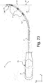
- a similar feature is embodied in the variant shown in Figures 23 to 27 , where a leading edge of the bevelled end 6*, at a distal extremity of the bevelled end 6*, is provided with at least one side bevel 615A*, 615B* defining a corresponding cutting edge 620A*, 620B* (see Figure 26 ).
- two side bevels 615A* and 615B* are likewise provided at the leading edge of the bevelled end 6*, leading to the definition of two corresponding cutting edges 620A* and 620B*.
- side bevels 615A*, 615B* similarly leads to sharper cutting edges 620A*, 620B*, improving the ability to cut through tissues.
- the side bevels 615A*, 615B* are likewise angled with respect to the longitudinal axis of the terminal end 5A* of the elongated rod member 5* and form an angle ⁇ 1* of the order of 50°.
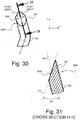
- Figures 28 to 31 illustrate yet another embodiment of the aforementioned feature, where a leading edge of the bevelled end 60*, at a distal extremity of the bevelled end 60*, is provided with at least one side bevel 615A**, 615B** defining a corresponding cutting edge 620A**, 620B** (see Figure 30 ).
- two side bevels 615A** and 615B** are once again provided at the leading edge of the bevelled end 60*, leading to the definition of two corresponding cutting edges 620A** and 620B**.
- the side bevels 615A** and 615B** are more pronounced, leading to a more angular configuration of the resulting cutting edges 620A**, 620B**, which likewise improves the ability to cut through tissues.
- the side bevels 615A**, 615B**, and resulting cutting edges 620A**, 620B** are angled with respect to the longitudinal axis of the terminal end 50A* of the elongated rod member 50* and form an angle ⁇ 2* of the order of 90° in this other example.
- parts of the curved or bent second portion of the elongated rod member 5, 50, 5*, resp. 50* can especially be exploited during surgery as a fulcrum to facilitate severance of the desired tissue.
- parts of the curved or bent second portion can suitably be used to bear on underlying tissues or onto an additional instrument inserted for that very purpose, thereby providing support for manipulation of the medical instrument during the severance operation.
- the medical instrument of the invention advantageously exhibits a minimal cross-section that in essence corresponds to the cross-section of the elongated rod member, which greatly facilitates penetration through the tissues, with minimal interference both during insertion of the medical instrument in the area to be treated and during withdrawal thereof.
- the limited cross-sectional area of the elongated member (which by way of preference does not exceed 5 mm 2 ) is such that surgery can be carried out in a truly percutaneous manner without this necessitating any incision at the point of entry of the medical instrument, but merely a puncture, which therefore heals without any noticeable scar for the patient, much like an intravenous infusion.
- the medical instrument of the invention is of simple construction and is therefore economical to produce.
- an end section of the elongated rod member 5, resp. 5*, at the terminal end 5A, resp. 5A*, of the second portion extends substantially perpendicularly to the first direction a1, namely along a second direction a2 that is parallel to the z axis.
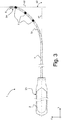
- angle ⁇ 2 depicted in Figures 3 and 23 is substantially 90°.
- the second portion of the elongated rod member 5, resp. 5* includes a single curved section 5a, resp. 5a*, extending over an angle ⁇ 1 (see Figure 2 which applies by analogy to the variant of Figures 23 to 27 ) that exceeds 60° and a radius of curvature R1 of the curved section 5a, resp. 5a*, is of the order of 30 to 45 mm.
- angle ⁇ 1 and radius of curvature R1 can be selected to equal approximately 68° and 37 mm, respectively, which values are not to be considered as limiting the scope of the invention.
- the illustrated arc shape allows the instrument to be introduced under or against the structure to be released into the sonography field without any interference between the handle portion of the instrument and the sonography probe all over the procedure. This shape also allows to withdraw the instrument without risk of causing involuntary lesion to surrounding soft tissue.
- a length L0 of handle portion 2 along the y axis can be of the order of 50 mm, while an overall length L1 of elongated rod member 5, resp. 5*, along the y axis can be of the order of 90 mm.
- a length L2 of the end section, along the z axis, at the terminal end 5A, resp. 5A* of elongated rod member 5, resp. 5*, can be of the order of 5 mm (or more).
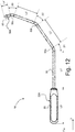
- the second portion of the elongated rod member 50, resp. 50* includes a multiplicity of, namely three, curved sections 50a, 50b, 50c, resp. 50a*, 50b*, 50c*, each extending over an angle ⁇ 1, ⁇ 2, resp. ⁇ 3 (see Figure 12 which applies by analogy to the variant of Figures 28 to 31 ) that does not exceed 40°.
- angles ⁇ 1, ⁇ 2, and ⁇ 3 can be selected to equal approximately 35°, which value is once again not to be considered as limiting the scope of the invention.
- the three curved sections 50a, 50b, 50c, resp. 50a*, 50b*, 50c* are separated by two substantially rectilinear sections having a length L2', resp. L3' of the order of 15 to 25 mm.
- lengths L2' and L3' are respectively of 22 mm and 17 mm.
- a length L0' of handle portion 20 along the y axis can be of the order of 28 mm, while a length L1' of the first, rectilinear portion of elongated rod member 50, resp. 50*, can be of the order of 30 mm.
- a length L4' of the end section, at the terminal end 50A, resp. 50A*, of elongated rod member 50, resp. 50*, can likewise be of the order of 5 mm (or less). In the variant of Figures 28 to 31 , such length L4' can for instance be reduced to approximately 2 to 3 mm.
- 50A* of the second portion, likewise extends along the second direction a2' substantially perpendicularly to the first direction a1', however with an angle ⁇ 4, as depicted in Figures 13 and 28 , that is of approximately 105° in the present instance.
- the illustrated angled shape similarly allows the instrument to be introduced under or against the structure to be released into the sonography field without any interference between the handle portion of the instrument and the sonography probe all over the procedure.
- This shape likewise also allows to withdraw the instrument without risk of causing involuntary lesion to surrounding soft tissue.
- the elongated rod member is provided with a plurality of markings that are designed to be distinguishable under sonography.
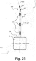
- markings are illustrated for instance in Figures 2 to 5 , 13 , 23 to 25 , 28 and 29 , and are identified by reference numerals 7, 70, 7* and 70*, respectively.
- These markings 7, 70, 7*, resp. 70* can in particular be embossings and can conveniently be distributed over the second portion of the elongated rod member 5, 50, 5*, resp. 50*, thus allowing the surgeon to precisely monitor the position of the medical instrument when performing percutaneous release procedures under the assistance of a sonography. Alignment of the markings 7, 70, 7*, resp.
- the sonography field with respect to the sonography probe in particular allows to ensure a proper and precise orientation of the medical instrument in the area to be treated.
- This visual assistance could furthermore include the superimposition of a virtual representation of the medical instrument on the sonographic imaging, if need be.
- the dimensions and/or distribution of the markings 7*, resp. 70*, along the elongated rod member 5*, resp. 50* could be non-uniform, to facilitate identification of the relevant orientation of the medical instrument under sonography.
- a visible marking 3 (such as a laser marking) may be provided on the handle portion 2 to likewise identify an orientation of the medical instrument when performing surgery.
- This visible marking 3 may in particular be provided on an inner face 2A of the handle portion 2 which is oriented in a same direction as the second portion of the elongated rod member 5, resp. 5*.
- a similar visible marking may be provided on the inner face 20A of the handle portion 20 of medical instrument 10, resp. 10*.
- the elongated rod member 5, 50, 500, 5*, resp. 50* has a substantially circular cross-section.
- a diameter of the elongated rod member 5, 50, 500, 5*, resp. 50* may in particular be of the order of 1 to 2 mm.
- the elongated rod member 5, 50, 500, 5*, resp. 50* is shown as being solid and non-hollow.
- a hollow rod member instead, which would provide for the ability to detect a possible bleeding through the relevant rod cavity, in case of damage to a blood vessel, and/or to inject a local anaesthetic using a dedicated syringe inserted in the relevant rod cavity.
- the use of a solid and non-hollow rod member however remains particularly advantageous in that the medical instrument is simpler and more cost-efficient to produce.
- the medical instrument of the invention can in particular be used for the purpose of performing percutaneous release procedures on upper or lower limbs, especially under the assistance of a sonography. Other uses could however be contemplated.
- each bevelled surface is substantially planar or exhibits a slight curvature, be it slightly concave or convex.
- the plane of the bevelled surface can generally be defined as a plane that best approximates the bevelled surface.
- the medical instrument of the invention could be specifically designed for single use.
- the handle portion could be specifically designed to melt in case of resterilization, for instance by using a thermoplastic material.
Abstract
A medical instrument (1) for percutaneous release procedures, especially on upper or lower limbs, such as percutaneous carpal tunnel release or percutaneous A1 pulley release. The medical instrument (1) comprises a handle portion (2) designed to allow handling, orientation and manipulation of the medical instrument (1) and an elongated rod member (5) secured to the handle portion (2) and extending within a defined plane (P0). A first portion of the elongated rod member (5) extends along a first direction (a1) within the defined plane (P0) away from the handle portion (2), and a second portion of the elongated rod member (5), downstream of the first portion, is curved and/or bent within the defined plane (P0). A free end of the elongated rod member (5), at a terminal end (5A) of the second portion, is shaped as a bevelled end (6) exhibiting a bevelled surface (6A), which bevelled end (6) is designed to act as a cutting device to severe tissue, the bevelled surface (6A) being inclined with respect to the defined plane (P0).
Description
- The present invention generally relates to a medical instrument for percutaneous release procedures, especially percutaneous release procedures on upper or lower limbs, such as but not limited to percutaneous carpal tunnel release or percutaneous A1 pulley release.
- Carpal tunnel syndrome (CTS) and trigger finger syndrome (TFS) can conveniently be treated by percutaneous release procedures. These minimally invasive procedures are typically carried out using simple puncture needles or more complex hook knives or push knives. Such medical instruments are also used for other minimally invasive release procedures on upper or lower limbs, such as for the treatment of Morton's neuroma, tarsal tunnel release, de Quervain syndrome, epicondylalgy, shoulder surgery, and similar release procedures.
- While these medical instruments may be reasonably satisfactory, there remains a need for an improved solution.
- A general aim of the invention is to provide an improved medical instrument for percutaneous release procedures, especially percutaneous release procedures on upper or lower limbs, such as percutaneous carpal tunnel release or percutaneous A1 pulley release, as well as other percutaneous release procedures used in the treatment of the conditions or syndromes listed in the background of the present invention.
- This general aim is achieved thanks to the solution defined in
claim 1, namely a medical instrument for percutaneous release procedures, comprising a handle portion designed to allow handling, orientation and manipulation of the medical instrument by a surgeon and an elongated rod member secured to the handle portion and extending substantially within a defined plane. A first portion of the elongated rod member extends substantially along a first direction within the defined plane away from the handle portion, and a second portion of the elongated rod member, downstream of the first portion, is curved and/or bent within the defined plane. Furthermore, a free end of the elongated rod member, at a terminal end of the second portion, is shaped as a bevelled end exhibiting a bevelled surface, which bevelled end is designed to act as a cutting device to severe tissue, said bevelled surface being inclined with respect to the defined plane. - Advantageous embodiments of the invention form the subject-matter of the dependent claims and are discussed below.
- According to a preferred embodiment of the invention, an angle of inclination of a plane comprising the bevelled surface with respect to the defined plane is of the order of 10° to 40°. Even more preferably, the angle of inclination is of the order of 15° to 30°.
- Advantageously, an end section of the elongated rod member, at the terminal end of the second portion, extends substantially perpendicularly to the first direction. The end section of the elongated rod member may in particular extend along a second direction that forms an angle with respect to the first direction that is comprised between 80° and 120°.
- By way of preference, the first portion of the elongated rod member is a substantially rectilinear section.
- According to an embodiment of the invention, the second portion includes at least one curved section extending over an angle that exceeds 30°. In accordance with a first variant of this embodiment, the second portion includes a single curved section extending over an angle that exceeds 60° and a radius of curvature of the curved section is preferably of the order of 30 to 45 mm. In this context, an end section of the elongated rod member, at the terminal end of the second portion, may in particular extend along a second direction perpendicularly to the first direction. In accordance with a second variant of this embodiment, the second portion includes multiple, especially three, curved sections each extending over an angle that does not exceed 40°. In this context, the multiple curved sections may in particular be separated by substantially rectilinear sections having a length of the order of 15 to 25 mm.
- According to a particularly advantageous embodiment of the invention, the elongated rod member is provided with a plurality of markings, such as embossings, designed to be distinguishable under sonography. These markings are preferably distributed over the second portion of the elongated rod member.
- According to yet another advantageous embodiment of the invention, the bevelled end exhibits at least two bevelled surfaces with distinct angles of inclination. In a manner similar to the aforementioned markings, the at least two bevelled surfaces facilitate location and orientation of the terminal end of the medical instrument under sonography as the bevelled surfaces will generate different sonographic echoes or signatures due to the distinct angles of inclination.
- According to a further embodiment of the invention, a leading edge of the bevelled end, at a distal extremity of the bevelled end, is provided with at least one side bevel defining a cutting edge.
- Advantageously, the handle portion of the medical instrument may be provided with a visible marking, such as a laser marking, which visible marking is preferably provided on an inner face of the handle portion which is oriented in a same direction as the second portion of the elongated rod member.
- By way of preference, a cross-sectional area of the elongated rod member does not exceed 5 mm2. A diameter of the elongated rod member may in particular be of the order of 1 to 2 mm.
- According to a particularly preferred embodiment of the invention, the elongated rod member has a substantially circular cross-section. The elongated rod member may furthermore be solid and non-hollow.
- Also claimed in the use of the medical instrument of the invention for the purpose of performing percutaneous release procedures on upper or lower limbs, especially for the purpose of performing percutaneous carpal tunnel release or for the purpose of performing percutaneous A1 pulley release.
- By way of preference, the medical instrument of the invention is used for the purpose of performing percutaneous release procedures, the percutaneous release procedures being performed under the assistance of a sonography. In this context, the medical instrument may in particular be a medical instrument in accordance with
claim 8 or 9, the plurality of markings or the at least two bevelled surfaces being exploited for the purpose of orienting the medical instrument during the percutaneous release procedures. - Other features and advantages of the present invention will appear more clearly from reading the following detailed description of embodiments of the invention which are presented solely by way of non-restrictive examples and illustrated by the attached drawings in which:
-
Figure 1 is a perspective view of a medical instrument in accordance with a first embodiment of the invention, which medical instrument is particularly suited for percutaneous carpal tunnel release in the treatment of the carpal tunnel syndrome; -
Figure 2 is a side view of the medical instrument ofFigure 1 as seen along the x axis of a Cartesian coordinate system x-y-z as reproduced inFigure 1 , with the elongated rod member of the medical instrument extending substantially within a defined plane that is parallel to the vertical plane formed by the y and z axes; -
Figure 3 is another side view of the medical instrument ofFigure 1 as seen along the x axis; -
Figure 4 is a top view of the medical instrument ofFigure 1 as seen along the z axis; -
Figure 5 is a rear view of the medical instrument ofFigure 1 as seen along the y axis; -
Figure 6 is an enlarged view of a terminal end of the medical instrument ofFigure 1 as identified by detail A inFigure 5 ; -
Figure 7 is a perspective view of a handle portion of the medical instrument ofFigure 1 ; -
Figure 8 is a side view of the handle portion ofFigure 7 where a visible marking is provided; -
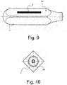
Figure 9 is another side view of the handle portion ofFigure 7 taken from a different perspective; -
Figure 10 is a front view of the handle portion ofFigure 7 where the handle portion is secured to the elongated rod member of the medical instrument; -
Figure 11 is a perspective view of a medical instrument in accordance with another embodiment of the invention, which medical instrument is particularly suited for percutaneous A1 pulley release in the treatment of the trigger finger syndrome; -
Figure 12 is a side view of the medical instrument ofFigure 11 as seen along the x axis of a Cartesian coordinate system x-y-z as reproduced inFigure 11 , with the elongated rod member of the medical instrument extending substantially within a defined plane that is parallel to the vertical plane formed by the y and z axes; -
Figure 13 is another side view of the medical instrument ofFigure 11 as seen along the x axis; -
Figure 14 is a front view of the medical instrument ofFigure 11 as seen along the y axis; -
Figure 15 is an enlarged view of a terminal end of the medical instrument ofFigure 11 as identified by detail B inFigure 13 ; -
Figure 16 is a cross-sectional view of the terminal end of the medical instrument ofFigure 11 as taken along sectional plane C-C reproduced inFigure 15 ; -
Figure 17 is a perspective view of a handle portion of the medical instrument ofFigure 11 ; -
Figure 18 is a side view of the handle portion ofFigure 17 ; -
Figure 19 is another side view of the handle portion ofFigure 17 taken from a different perspective; -
Figure 20 is a front view of the handle portion ofFigure 17 where the handle portion is secured to the elongated rod member of the medical instrument; -
Figure 21A is a top view of a terminal end of a medical instrument showing a configuration of the bevelled end of the medical instrument in accordance with another embodiment of the present invention, which configuration is also applicable in the context of the medical instruments ofFigures 1 to 20 ; -
Figure 21B is a side view showing the configuration of the bevelled end of the medical instrument ofFigure 21A ; -
Figure 22A is a cross-sectional view of the terminal end of the elongated rod member of the medical instrument ofFigures 21A and 21B as taken along sectional plane D-D reproduced inFigures 21A and 21B , upstream of the bevelled end; -
Figure 22B is a cross-sectional view of the terminal end of the elongated rod member of the medical instrument ofFigures 21A and 21B as taken along sectional plane E-E reproduced inFigures 21A and 21B passing through a first portion of the bevelled end; -
Figure 22C is a cross-sectional view of the terminal end of the elongated rod member of the medical instrument ofFigures 21A and 21B as taken along sectional plane F-F reproduced inFigures 21A and 21B passing through a second portion of the bevelled end; -
Figure 22D is a front view of the terminal end of the elongated rod member of the medical instrument ofFigures 21A and 21B ; -
Figure 23 is a side view of a variant of the medical instrument ofFigures 1 to 10 as seen along the x axis of a Cartesian coordinate system x-y-z, with the elongated rod member of the medical instrument extending substantially within a defined plane that is parallel to the vertical plane formed by the y and z axes; -
Figure 24 is a top view of the medical instrument ofFigure 23 as seen along the z axis; -
Figure 25 is a rear view of the medical instrument ofFigure 23 as seen along the y axis; -
Figure 26 is an enlarged view of a terminal end of the medical instrument ofFigure 23 as seen along the x axis; -
Figure 27 is a cross-sectional view of the terminal end of the medical instrument ofFigure 23 as taken along sectional plane G-G reproduced inFigure 26 ; -
Figure 28 is a side view of a variant of the medical instrument ofFigure 11 to 20 as seen along the x axis of a Cartesian coordinate system x-y-z, with the elongated rod member of the medical instrument extending substantially within a defined plane that is parallel to the vertical plane formed by the y and z axes; -
Figure 29 is a front view of the medical instrument ofFigure 28 as seen along the y axis; -
Figure 30 is an enlarged view of a terminal end of the medical instrument ofFigure 28 as seen along the x axis; and -
Figure 31 is a cross-sectional view of the terminal end of the medical instrument ofFigure 28 as taken along sectional plane H-H reproduced inFigure 30 . - The present invention will be described in relation to various illustrative embodiments. It shall be understood that the scope of the invention encompasses all combinations and sub-combinations of the features of the medical instruments disclosed herein.
- As described herein, when two or more parts or components are described as being connected, attached, secured or coupled to one another, they can be so connected, attached, secured or coupled directly to each other or through one or more intermediary parts.
- Referring to
Figures 1 to 10 , there is shown a first embodiment of a medical instrument, designated byreference numeral 1, in accordance with the present invention, which first embodiment is particularly suited for percutaneous carpal tunnel release in the treatment of the carpal tunnel syndrome (CTS). A variant of this first embodiment, designated byreference numeral 1*, is further shown inFigures 23 to 27 . - Referring to
Figures 11 to 20 , there is shown another embodiment of a medical instrument, designated byreference numeral 10, in accordance with the present invention, which other embodiment is particularly suited for percutaneous A1 pulley release in the treatment of the trigger finger syndrome (TFS). A variant of this second embodiment, designated byreference numeral 10*, is further shown inFigures 28 to 31 . - All embodiments share a number of common features, including a
handle portion 2, resp. 20, designed to allow handling, orientation and manipulation of the medical instrument by a surgeon and anelongated rod member handle portion 2, resp. 20, and extending substantially within a defined plane, designated by reference P0. Referring to the Cartesian coordinate system x-y-z reproduced in the drawings, this defined plane P0 is assumed to be a vertical plane parallel to the vertical plane formed by the y and z axes. - As shown in the illustrations (see especially
Figures 3 ,13 ,23 and28 ), a first portion of theelongated rod member handle portion 2, resp. 20, namely parallel to the y axis. This first portion can especially be a substantially rectilinear section. In addition, a second portion of theelongated rod member elongated rod member terminal end bevelled end bevelled surface 6A (seeFigures 5 and6 ), 60A (seeFigures 14 to 16 ), 6A* (seeFigures 25 to 27 ), resp. 60A* (seeFigures 29 to 31 ). Thisbevelled end bevelled surface 6A,.60A, 6A*, resp. 60A*, being inclined with respect to the defined plane P0. - By way of preference, the angle of inclination θ1, θ2, θ1*, resp. θ2*, of a plane P, P', P*, resp. P**, comprising the
bevelled surface 6A (seeFigure 6 ), 60A (seeFigure 16 ), 6A* (seeFigure 27 ), resp. 60A* (seeFigure 31 ) with respect to the defined plane P0 is of the order of 10° to 40°, even more preferably of the order of 15° to 30°. In the examples ofFigures 1 to 20 and28 to 31 , angles of inclination θ1, θ2 and θ2* are each of the order of 30°, whereas in the example ofFigures 23 to 27 , angle of inclination θ1* is of the order of 15°. -
Figures 21A-B and22A-D show a configuration of abevelled end 600, at aterminal end 500A of anelongated rod member 500 of a medical instrument in accordance with another embodiment of the present invention. This configuration is especially applicable in the context of the aforementioned medical instruments as shown inFigures 1 to 20 . - In contrast to the embodiments shown in
Figures 1 to 20 where thebevelled end 6, resp. 60, exhibits a singlebevelled surface 6A, resp. 60A, thebevelled end 600 shown inFigures 21A-B and22A-D exhibits at least twobevelled surfaces terminal end 500A of the medical instrument under sonography as the bevelled surfaces 600A, 610A will generate different sonographic echoes or signatures due to the distinct angles of inclination θ3, θ4. - In the context of the configuration shown in
Figures 21A-B and22A-D , the angle of inclination θ3 of the plane P" comprising thebevelled surface 600A with respect to the defined plane P0 is of the order of 15° and the angle of inclination θ4 of the plane P"' comprising thebevelled surface 610A with respect to the defined plane P0 is of the order of 30°. -
Figures 21A-B and22A-D further illustrate another advantageous feature in accordance with a further embodiment of the invention, which feature is likewise applicable in the context of the aforementioned medical instruments as shown inFigures 1 to 20 , independently of the number of bevelled surfaces. As shown inFigures 21A-B and22A-D , a leading edge of thebevelled end 600, at a distal extremity of thebevelled end 600, is provided with at least oneside bevel corresponding cutting edge Figures 21A-B and22A-D , twoside bevels bevelled end 600, leading to the definition of twocorresponding cutting edges Figure 22C , the provision of the side bevels 615A, 615B leads tosharper cutting edges bevelled end 600, rather than on both sides as illustrated. - In the illustrations of
Figures 21A-B and22A-D , the side bevels 615A, 615B are angled with respect to the longitudinal axis of theterminal end 500A of theelongated rod member 500 and form an angle γ1 of the order of 50°. - A similar feature is embodied in the variant shown in
Figures 23 to 27 , where a leading edge of thebevelled end 6*, at a distal extremity of thebevelled end 6*, is provided with at least oneside bevel 615A*, 615B* defining acorresponding cutting edge 620A*, 620B* (seeFigure 26 ). In the example ofFigures 23 to 27 , twoside bevels 615A* and 615B* are likewise provided at the leading edge of thebevelled end 6*, leading to the definition of twocorresponding cutting edges 620A* and 620B*. The provision of the side bevels 615A*, 615B* similarly leads tosharper cutting edges 620A*, 620B*, improving the ability to cut through tissues. The side bevels 615A*, 615B* are likewise angled with respect to the longitudinal axis of theterminal end 5A* of theelongated rod member 5* and form an angle γ1* of the order of 50°. -
Figures 28 to 31 illustrate yet another embodiment of the aforementioned feature, where a leading edge of thebevelled end 60*, at a distal extremity of thebevelled end 60*, is provided with at least oneside bevel 615A**, 615B** defining acorresponding cutting edge 620A**, 620B** (seeFigure 30 ). In the example ofFigures 28 to 31 , twoside bevels 615A** and 615B** are once again provided at the leading edge of thebevelled end 60*, leading to the definition of twocorresponding cutting edges 620A** and 620B**. In contrast to the previous examples, the side bevels 615A** and 615B** are more pronounced, leading to a more angular configuration of the resultingcutting edges 620A**, 620B**, which likewise improves the ability to cut through tissues. The side bevels 615A**, 615B**, and resultingcutting edges 620A**, 620B** are angled with respect to the longitudinal axis of theterminal end 50A* of theelongated rod member 50* and form an angle γ2* of the order of 90° in this other example. - Turning back to the illustrations of
Figures 1 to 20 and23 to 31 , parts of the curved or bent second portion of theelongated rod member - It will also be appreciated that the medical instrument of the invention advantageously exhibits a minimal cross-section that in essence corresponds to the cross-section of the elongated rod member, which greatly facilitates penetration through the tissues, with minimal interference both during insertion of the medical instrument in the area to be treated and during withdrawal thereof. Furthermore, the limited cross-sectional area of the elongated member (which by way of preference does not exceed 5 mm2) is such that surgery can be carried out in a truly percutaneous manner without this necessitating any incision at the point of entry of the medical instrument, but merely a puncture, which therefore heals without any noticeable scar for the patient, much like an intravenous infusion.
- As this will be appreciated from reading further the following description, the medical instrument of the invention is of simple construction and is therefore economical to produce.
- Referring more particularly to the first embodiment of
Figures 1 to 10 and the variant ofFigures 23 to 27 , one can note that an end section of theelongated rod member 5, resp. 5*, at theterminal end 5A, resp. 5A*, of the second portion, extends substantially perpendicularly to the first direction a1, namely along a second direction a2 that is parallel to the z axis. In other words, angle α2 depicted inFigures 3 and23 is substantially 90°. - According to this first embodiment, and the variant thereof, the second portion of the
elongated rod member 5, resp. 5*, includes a singlecurved section 5a, resp. 5a*, extending over an angle α1 (seeFigure 2 which applies by analogy to the variant ofFigures 23 to 27 ) that exceeds 60° and a radius of curvature R1 of thecurved section 5a, resp. 5a*, is of the order of 30 to 45 mm. By way of illustration, angle α1 and radius of curvature R1 can be selected to equal approximately 68° and 37 mm, respectively, which values are not to be considered as limiting the scope of the invention. In this instance, it may be appreciated that the end section of theelongated rod member 5, resp. 5*, at theterminal end 5A, resp. 5A*, of the second portion, is bent with respect to the end of thecurved section 5a, resp. 5a*, by an angle of approximately 30°, so that the end section extends substantially perpendicularly to the first direction a1. - The illustrated arc shape allows the instrument to be introduced under or against the structure to be released into the sonography field without any interference between the handle portion of the instrument and the sonography probe all over the procedure. This shape also allows to withdraw the instrument without risk of causing involuntary lesion to surrounding soft tissue.
- By way of further illustration, a length L0 of
handle portion 2 along the y axis can be of the order of 50 mm, while an overall length L1 ofelongated rod member 5, resp. 5*, along the y axis can be of the order of 90 mm. A length L2 of the end section, along the z axis, at theterminal end 5A, resp. 5A* ofelongated rod member 5, resp. 5*, can be of the order of 5 mm (or more). - Referring more particularly to the other embodiments of
Figures 11 to 20 and28 to 31 , one can note that the second portion of theelongated rod member 50, resp. 50*, includes a multiplicity of, namely three,curved sections Figure 12 which applies by analogy to the variant ofFigures 28 to 31 ) that does not exceed 40°. By way of illustration, angles β1, β2, and β3 can be selected to equal approximately 35°, which value is once again not to be considered as limiting the scope of the invention. - In accordance with this other embodiment, the three
curved sections - By way of further illustration, a length L0' of
handle portion 20 along the y axis can be of the order of 28 mm, while a length L1' of the first, rectilinear portion ofelongated rod member 50, resp. 50*, can be of the order of 30 mm. A length L4' of the end section, at theterminal end 50A, resp. 50A*, ofelongated rod member 50, resp. 50*, can likewise be of the order of 5 mm (or less). In the variant ofFigures 28 to 31 , such length L4' can for instance be reduced to approximately 2 to 3 mm. In this second embodiment, the end section of theelongated rod member 50, resp. 50*, at theterminal end 50A, resp. 50A*, of the second portion, likewise extends along the second direction a2' substantially perpendicularly to the first direction a1', however with an angle β4, as depicted inFigures 13 and28 , that is of approximately 105° in the present instance. - The illustrated angled shape similarly allows the instrument to be introduced under or against the structure to be released into the sonography field without any interference between the handle portion of the instrument and the sonography probe all over the procedure. This shape likewise also allows to withdraw the instrument without risk of causing involuntary lesion to surrounding soft tissue.
- By way of preference, the elongated rod member is provided with a plurality of markings that are designed to be distinguishable under sonography. Such markings are illustrated for instance in
Figures 2 to 5 ,13 ,23 to 25 ,28 and29 , and are identified byreference numerals markings elongated rod member markings relevant markings - By way of preference, as schematically illustrated in
Figures 23 to 25 ,28 and29 , the dimensions and/or distribution of themarkings 7*, resp. 70*, along theelongated rod member 5*, resp. 50*, could be non-uniform, to facilitate identification of the relevant orientation of the medical instrument under sonography. - Advantageously, as illustrated in
Figures 1 to 10 (see alsoFigures 23 to 27 ), a visible marking 3 (such as a laser marking) may be provided on thehandle portion 2 to likewise identify an orientation of the medical instrument when performing surgery. Thisvisible marking 3 may in particular be provided on aninner face 2A of thehandle portion 2 which is oriented in a same direction as the second portion of theelongated rod member 5, resp. 5*. While not specifically illustrated inFigures 11 to 20 and28 to 31 , a similar visible marking may be provided on theinner face 20A of thehandle portion 20 ofmedical instrument 10, resp. 10*. - By way of preference, the
elongated rod member elongated rod member - In the illustrations of
Figures 1 to 31 , one may appreciate that theelongated rod member - The medical instrument of the invention can in particular be used for the purpose of performing percutaneous release procedures on upper or lower limbs, especially under the assistance of a sonography. Other uses could however be contemplated.
- Various modifications and/or improvements may be made to the above-described embodiments without departing from the scope of the invention as defined by the annexed claims. In particular, while embodiments of the invention have been described for the purpose of carrying out percutaneous carpal tunnel release and percutaneous A1 pulley release, the invention is generally applicable to any percutaneous release procedure, be it on upper or lower limbs, or other parts of the body, such as the neck or spine.
- Furthermore, while the embodiments show medical instruments where the bevelled end exhibits one or more strictly planar bevelled surfaces, the claims shall be construed as encompassing all variants where each bevelled surface is substantially planar or exhibits a slight curvature, be it slightly concave or convex. By way of convention, the plane of the bevelled surface can generally be defined as a plane that best approximates the bevelled surface.
- The medical instrument of the invention could be specifically designed for single use. In that respect, and in order to prevent reuse of the medical instrument, the handle portion could be specifically designed to melt in case of resterilization, for instance by using a thermoplastic material.
-
- 1
- medical instrument according to the invention (first embodiment)
- 2
- handle portion of
medical instrument 1, resp. 1* - 2A
- inner face of
handle portion 2 - 2B
- mounting hole provided on
handle portion 2 for securing theelongated rod member 5, resp. 5* (e.g. by mechanical press-in insertion and/or glueing) - 3
- marking (e.g. laser marking) on
inner face 2A ofhandle portion 2 - 5
- elongated rod member of
medical instrument 1 extending within defined plane P0 - 5a
- (single) curved section of
elongated rod member 5 - 5A
- terminal end of (second portion of)
elongated rod member 5 - 6
- bevelled end, at
terminal end 5A ofelongated rod member 5, designed to act as a cutting device to severe tissue - 6A
- bevelled surface of
bevelled end 6 - 7
- markings (e.g. embossings) provided along
elongated rod member 5 designed to be distinguishable under sonography - 1*
- medical instrument according to the invention (variant of first embodiment)
- 5*
- elongated rod member of
medical instrument 1* extending within defined plane P0 - 5a*
- (single) curved section of
elongated rod member 5* - 5A*
- terminal end of (second portion of)
elongated rod member 5* - 6*
- bevelled end, at
terminal end 5A* ofelongated rod member 5*, designed to act as a cutting device to severe tissue - 6A*
- bevelled surface of
bevelled end 6* - 7*
- markings (e.g. embossings) provided along
elongated rod member 5* designed to be distinguishable under sonography - L0
- length of
handle portion 2 along the y axis - L1
- overall length of
elongated rod member 5 along the y axis - L2
- length of end section at
terminal end 5A ofelongated rod member 5 along the z axis - R1
- radius of curvature of
curved section 5a, resp. 5a* - a1
- general direction of extension of first portion of
elongated rod member 5, resp. 5* ("first direction") - a2
- general direction of extension of end section at
terminal end 5A, resp. 5A* ofelongated member 5, resp. 5* ("second direction") - α1
- angle of
curved section 5a, resp. 5a* - α2
- total angle of curvature of
elongated rod member 5, resp. 5* / angle formed between first and second directions a1 and a2 (e.g. ∼ 90°) - θ1
- angle of bevelled
surface 6A with respect to defined plane P0 - α1*
- angle of bevelled
surface 6A* with respect to defined plane P0 - 10
- medical instrument according to the invention (second embodiment)
- 20
- handle portion of
medical instrument 10, resp. 10* - 20A
- inner face of
handle portion 20 - 20B
- mounting hole provided on
handle portion 20 for securing theelongated rod member 50, resp. 50* (e.g. by mechanical press-in insertion and/or glueing) - 50
- elongated rod member of
medical instrument 10 extending within defined plane P0 - 50a
- (first) curved section of
elongated rod member 50 - 50b
- (second) curved section of
elongated rod member 50 - 50c
- (third) curved section of
elongated rod member 50 - 50A
- terminal end of (second portion of)
elongated rod member 50 - 60
- bevelled end, at
terminal end 50A ofelongated rod member 50, designed to act as a cutting device to severe tissue - 60A
- bevelled surface of
bevelled end 60 - 70
- markings (e.g. embossings) provided along
elongated rod member 50 designed to be distinguishable under sonography - 10*
- medical instrument according to the invention (variant of second embodiment)
- 50*
- elongated rod member of
medical instrument 10* extending within defined plane P0 - 50a*
- (first) curved section of
elongated rod member 50* - 50b*
- (second) curved section of
elongated rod member 50* - 50c*
- (third) curved section of
elongated rod member 50* - 50A*
- terminal end of (second portion of)
elongated rod member 50* - 60*
- bevelled end, at
terminal end 50A* ofelongated rod member 50*, designed to act as a cutting device to severe tissue - 60A*
- bevelled surface of
bevelled end 60* - 70*
- markings (e.g. embossings) provided along
elongated rod member 50* designed to be distinguishable under sonography - L0'
- length of
handle portion 20 along the y axis - L1'
- length of first portion of
elongated rod member 50, resp. 50* along the y axis - L2'
- length of rectilinear section between first and second
curved sections - L3'
- length of rectilinear section between second and third
curved sections - L4'
- length of end section at
terminal end 50A, resp. 50A* ofelongated rod member 50, resp. 50* - a1'
- general direction of extension of first portion of
elongated rod member 50, resp. 50* ("first direction") - a2'
- general direction of extension of end section at
terminal end 50A, resp. 50A* ofelongated member 50, resp. 50* ("second direction") - β1
- angle of first
curved section 50a, resp. 50a* - β2
- angle of second
curved section 50b, resp. 50b* - β3
- angle of third
curved section 50c, resp. 50c* - β4
- total angle of curvature of
elongated rod member 50, resp. 50* / angle formed between first and second directions a1' and a2' (e.g. ∼ 105°) - θ2
- angle of
bevelled surface 60A with respect to defined plane P0 - θ2*
- angle of
bevelled surface 60A* with respect to defined plane P0 - 500
- elongated rod member of medical instrument extending within defined plane P0
- 500A
- terminal end of (second portion of)
elongated rod member 500 - 600
- bevelled end, at
terminal end 500A ofelongated rod member 500, designed to act as a cutting device to severe tissue - 600A
- (first) bevelled surface of
bevelled end 600 - 610A
- (second) bevelled surface of
bevelled end 600 - 615A
- (first) side bevel provided on leading edge of
bevelled end 600 and defining a corresponding (first) cuttingedge 620A - 615B
- (second) side bevel provided on leading edge of
bevelled end 600 and defining a corresponding (second) cuttingedge 620B - 620A
- (first) cutting edge at leading edge of
bevelled end 600 - 620B
- (second) cutting edge at leading edge of
bevelled end 600 - γ1
- angle formed by
side bevels - θ3
- angle of
bevelled surface 600A with respect to defined plane P0 - θ4
- angle of
bevelled surface 610A with respect to defined plane P0 - 615A*
- (first) side bevel provided on leading edge of
bevelled end 6* and defining a corresponding (first) cuttingedge 620A* - 615B*
- (second) side bevel provided on leading edge of
bevelled end 6* and defining a corresponding (second) cuttingedge 620B* - 620A*
- (first) cutting edge at leading edge of
bevelled end 6* - 620B*
- (second) cutting edge at leading edge of
bevelled end 6* - γ1*
- angle formed by
side bevels 615A*, 615B* - 615A**
- (first) side bevel provided on leading edge of
bevelled end 60* and defining a corresponding (first) cuttingedge 620A** - 615B**
- (second) side bevel provided on leading edge of
bevelled end 60* and defining a corresponding (second) cuttingedge 620B** - 620A**
- (first) cutting edge at leading edge of
bevelled end 60* - 620B**
- (second) cutting edge at leading edge of
bevelled end 60* - γ2*
- angle formed by cutting
edges 620A**, 620B** - x, y, z
- Cartesian coordinate system
- P0
- defined plane in which the
elongated rod member - P
- plane of bevelled
surface 6A - P'
- plane of
bevelled surface 60A - P"
- plane of
bevelled surface 600A - P"'
- plane of
bevelled surface 610A - P*
- plane of bevelled
surface 6A* - P**
- plane of
bevelled surface 60A*
Claims (15)
- A medical instrument (1; 10; 1*; 10*) for percutaneous release procedures, comprising a handle portion (2; 20) designed to allow handling, orientation and manipulation of the medical instrument (1; 10; 1*; 10*) by a surgeon and an elongated rod member (5; 50; 500; 5*; 50*) secured to the handle portion (2; 20) and extending substantially within a defined plane (P0),
wherein a first portion of the elongated rod member (5; 50; 500; 5*; 50*) extends substantially along a first direction (a1; a1') within the defined plane (P0) away from the handle portion (2; 20),
wherein a second portion of the elongated rod member (5; 50; 500; 5*; 50*), downstream of the first portion, is curved and/or bent within the defined plane (P0),
and wherein a free end of the elongated rod member (5; 50; 500; 5*; 50*), at a terminal end (5A; 50A; 500A; 5A*; 50A*) of the second portion, is shaped as a bevelled end (6; 60; 600; 6*; 60*) exhibiting a bevelled surface (6A; 60A; 600A, 610A; 6A*; 60A*), which bevelled end (6; 60; 600; 6*; 60*) is designed to act as a cutting device to severe tissue, said bevelled surface (6A; 60A; 600A, 610A; 6A*; 60A*) being inclined with respect to the defined plane (P0). - The medical instrument (1; 10; 1*; 10*) according to claim 1, wherein an angle of inclination (θ1; θ2; θ3, θ4; θ1*; θ2*) of a plane (P; P'; P", P"'; P*; P**) comprising the bevelled surface (6A; 60A; 600A, 610A; 6A*; 60A*) with respect to the defined plane (P0) is of the order of 10° to 40°, preferably of the order of 15° to 30°.
- The medical instrument (1; 10; 1*; 10*) according to claim 1 or 2, wherein an end section of the elongated rod member (5; 50; 500; 5*; 50*), at the terminal end (5A; 50A; 500A; 5A*; 50A*) of the second portion, extends substantially perpendicularly to the first direction (a1; a1'),
and wherein the end section of the elongated rod member (5; 50; 500; 5*; 50*) preferably extends along a second direction (a2; a2') that forms an angle (α2; β4) with respect to the first direction (a1; a1') that is comprised between 80° and 120°. - The medical instrument (1; 10; 1*; 10*) according to any one of the preceding claims, wherein the first portion of the elongated rod member (5; 50; 500; 5*; 50*) is a substantially rectilinear section.
- The medical instrument (1; 10; 1*; 10*) according to any one of the preceding claims, wherein the second portion includes at least one curved section (5a; 50a, 50b, 50c; 5a*; 50a*, 50b*, 50c*) extending over an angle (α1; β1, β2, β3) that exceeds 30°.
- The medical instrument (1; 1*) according to claim 5, wherein the second portion includes a single curved section (5a; 5a*) extending over an angle (a1) that exceeds 60° and wherein a radius of curvature (R1) of the curved section (5a; 5a*) is preferably of the order of 30 to 45 mm,
and wherein an end section of the elongated rod member (5; 5*), at the terminal end (5A; 5A*) of the second portion, preferably extends along a second direction (a2) perpendicularly to the first direction (a1). - The medical instrument (10; 10*) according to claim 5, wherein the second portion includes multiple, especially three, curved sections (50a, 50b, 50c; 50a*, 50b*, 50c*) each extending over an angle (β1, β2, β3) that does not exceed 40°,
and wherein the multiple curved sections (50a, 50b, 50c; 50a*, 50b*, 50c*) are preferably separated by substantially rectilinear sections having a length (L2', L3') of the order of 15 to 25 mm. - The medical instrument (1; 10; 1*; 10*) according to any one of the preceding claims, wherein the elongated rod member (5; 50; 500; 5*; 50*) is provided with a plurality of markings (7; 70; 7*; 70*), such as embossings, designed to be distinguishable under sonography,
and wherein the markings (7; 70; 7*; 70*) are preferably distributed over the second portion of the elongated rod member (5; 50; 500; 5*; 50*). - The medical instrument according to any one of the preceding claims, wherein the bevelled end (600) exhibits at least two bevelled surfaces (600A, 610A) with distinct angles of inclination (θ3, θ4).
- The medical instrument (1*; 10*) according to any one of the preceding claims, wherein a leading edge of the bevelled end (600; 6*; 60*), at a distal extremity of the bevelled end (600; 6*; 60*), is provided with at least one side bevel (615A, 615B; 615A*; 615B*; 615A**, 615B**) defining a cutting edge (620A, 620B; 620A*, 620B*; 620A**, 620B**).
- The medical instrument (1; 10; 1*; 10*) according to any one of the preceding claims, wherein the handle portion (2; 20) is provided with a visible marking (3), such as a laser marking,
and wherein the visible marking (3) is preferably provided on an inner face (2A; 20A) of the handle portion (2; 20) which is oriented in a same direction as the second portion of the elongated rod member (5; 50; 500; 5*; 50*). - The medical instrument (1; 10; 1*; 10*) according to any one of the preceding claims, wherein a cross-sectional area of the elongated rod member (5; 50; 500; 5*; 50*) does not exceed 5 mm2 and wherein a diameter of the elongated rod member (5; 50; 500; 5*; 50*) is preferably of the order of 1 to 2 mm.
- The medical instrument (1; 10; 1*; 10*) according to any one of the preceding claims, wherein the elongated rod member (5; 50; 500; 5*; 50*) has a substantially circular cross-section and/or wherein the elongated rod member (5; 50; 500; 5*; 50*) is solid and non-hollow.
- Use of the medical instrument (1; 10; 1*; 10*) of any one of the preceding claims, for the purpose of performing percutaneous release procedures on upper or lower limbs, especially for the purpose of performing percutaneous carpal tunnel release or for the purpose of performing percutaneous A1 pulley release.
- Use of the medical instrument (1; 10; 1*; 10*) of any one of claims 1 to 13, for the purpose of performing percutaneous release procedures, wherein the percutaneous release procedures are performed under the assistance of a sonography,
and wherein the medical instrument (1; 10; 1*; 10*) is preferably a medical instrument (1; 10; 1*; 10*) in accordance with claim 8 or 9, the plurality of markings (7; 70; 7*; 70*) or the at least two bevelled surfaces (600A, 610A) being exploited for the purpose of orienting the medical instrument (1; 10; 1*; 10*) during the percutaneous release procedures.
Priority Applications (7)
| Application Number | Priority Date | Filing Date | Title |
|---|---|---|---|
| JP2020572397A JP7411236B2 (en) | 2018-06-29 | 2019-07-01 | Medical instruments for percutaneous open procedures |
| PCT/IB2019/055552 WO2020003263A1 (en) | 2018-06-29 | 2019-07-01 | Medical instrument for percutaneous release procedures |
| AU2019293657A AU2019293657A1 (en) | 2018-06-29 | 2019-07-01 | Medical instrument for percutaneous release procedures |
| CA3104846A CA3104846A1 (en) | 2018-06-29 | 2019-07-01 | Medical instrument for percutaneous release procedures |
| EP19736822.8A EP3813693B1 (en) | 2018-06-29 | 2019-07-01 | Medical instrument for percutaneous release procedures |
| CN201980056807.8A CN112638294A (en) | 2018-06-29 | 2019-07-01 | Medical device for percutaneous debonding procedures |
| US17/256,363 US20210369293A1 (en) | 2018-06-29 | 2019-07-01 | Medical instrument for percutaneous release procedures |
Applications Claiming Priority (1)
| Application Number | Priority Date | Filing Date | Title |
|---|---|---|---|
| EP18180894 | 2018-06-29 |
Publications (1)
| Publication Number | Publication Date |
|---|---|
| EP3586776A1 true EP3586776A1 (en) | 2020-01-01 |
Family
ID=62837782
Family Applications (2)
| Application Number | Title | Priority Date | Filing Date |
|---|---|---|---|
| EP18206119.2A Withdrawn EP3586776A1 (en) | 2018-06-29 | 2018-11-14 | Medical instrument for percutaneous release procedures |
| EP19736822.8A Active EP3813693B1 (en) | 2018-06-29 | 2019-07-01 | Medical instrument for percutaneous release procedures |
Family Applications After (1)
| Application Number | Title | Priority Date | Filing Date |
|---|---|---|---|
| EP19736822.8A Active EP3813693B1 (en) | 2018-06-29 | 2019-07-01 | Medical instrument for percutaneous release procedures |
Country Status (7)
| Country | Link |
|---|---|
| US (1) | US20210369293A1 (en) |
| EP (2) | EP3586776A1 (en) |
| JP (1) | JP7411236B2 (en) |
| CN (1) | CN112638294A (en) |
| AU (1) | AU2019293657A1 (en) |
| CA (1) | CA3104846A1 (en) |
| WO (1) | WO2020003263A1 (en) |
Cited By (1)
| Publication number | Priority date | Publication date | Assignee | Title |
|---|---|---|---|---|
| EP4176831A1 (en) * | 2021-11-07 | 2023-05-10 | Spirecut Sa | Medical instrument, in particular for percutaneous surgical/medical procedures |
Families Citing this family (3)
| Publication number | Priority date | Publication date | Assignee | Title |
|---|---|---|---|---|
| WO2020146458A1 (en) | 2019-01-11 | 2020-07-16 | Mayo Foundation For Medical Education And Research | Micro-invasive surgical device and methods of use |
| KR102539274B1 (en) * | 2020-12-23 | 2023-06-02 | 건양대학교산학협력단 | Safty cuved tunneler for chemoport insertion |
| IT202100032843A1 (en) * | 2021-12-28 | 2023-06-28 | Paul Douglas Paterson | Surgical cutting tool |
Citations (3)
| Publication number | Priority date | Publication date | Assignee | Title |
|---|---|---|---|---|
| US5029573A (en) * | 1990-03-30 | 1991-07-09 | Chow James C | System for endoscopic surgery |
| US5507800A (en) * | 1993-05-14 | 1996-04-16 | Strickland; James W. | Carpal tunnel tome and carpal tunnel release surgery |
| US8603124B1 (en) * | 2010-11-23 | 2013-12-10 | Robert Hatch | Modified surgical scalpel with polyurethane mated sheath for ultrasound assisted carpal tunnel surgery |
Family Cites Families (19)
| Publication number | Priority date | Publication date | Assignee | Title |
|---|---|---|---|---|
| US4955894A (en) * | 1984-10-30 | 1990-09-11 | Alcon Laboratories, Inc. | Posterior capsulotomy knife |
| US5282816A (en) * | 1991-09-20 | 1994-02-01 | Milres Corporation | Apparatus for subligamentous endoscopic transverse carpal ligament release surgery |
| US5222977A (en) * | 1992-02-21 | 1993-06-29 | Esser Rene D | Surgical needle with an adjustable eye |
| US5431153A (en) * | 1993-06-11 | 1995-07-11 | Lee; Hans | Surgical apparatus for assisting in the release of the carpal tunnel |
| US5411510A (en) * | 1993-07-06 | 1995-05-02 | Fugo; Richard J. | Surgical blade and method for ocular surgery |
| US5782850A (en) | 1994-10-12 | 1998-07-21 | Ro; Man Tack | Method for treating trigger finger, and medical instrument therefor |
| JP3914634B2 (en) * | 1998-04-23 | 2007-05-16 | 泉工医科工業株式会社 | Carpal tunnel opening procedure |
| US6019774A (en) * | 1998-12-10 | 2000-02-01 | Kinetikos Medical Incorporated | Carpal tunnel release apparatus and method |
| US7835784B2 (en) * | 2005-09-21 | 2010-11-16 | Medtronic Navigation, Inc. | Method and apparatus for positioning a reference frame |
| US8753364B2 (en) * | 2009-08-07 | 2014-06-17 | Thayer Intellectual Property, Inc. | Systems and methods for treatment of compressed nerves |
| US8840631B2 (en) * | 2009-10-29 | 2014-09-23 | Cook Medical Technologies Llc | Compartment syndrome treatment method and surgical instrument for same |
| JP5595522B2 (en) | 2010-01-14 | 2014-09-24 | サージカル イノベーション ヘルスケア カンパニー リミテッド | Surgical system |
| WO2015009763A1 (en) * | 2013-07-19 | 2015-01-22 | Ouroboros Medical, Inc. | An anti-clogging device for a vacuum-assisted, tissue removal system |
| US9610436B2 (en) * | 2013-11-12 | 2017-04-04 | Medtronic, Inc. | Implant tools with attachment feature and multi-positional sheath and implant techniques utilizing such tools |
| US10314605B2 (en) * | 2014-07-08 | 2019-06-11 | Benvenue Medical, Inc. | Apparatus and methods for disrupting intervertebral disc tissue |
| US9592071B2 (en) | 2014-10-27 | 2017-03-14 | J. Lee Berger | Grooved director with instrument guide |
| EP3393382A4 (en) * | 2015-12-23 | 2019-09-04 | The Regents of The University of Colorado, A Body Corporate | An ophthalmic knife and methods of use |
| WO2017176800A1 (en) * | 2016-04-04 | 2017-10-12 | HILTON, Kellen Arlen | Subcutaneous cutting device |
| CN207654202U (en) * | 2017-03-23 | 2018-07-27 | 柳松 | A kind of needle knife for treating stenosing tendon synovitis of flexor |
-
2018
- 2018-11-14 EP EP18206119.2A patent/EP3586776A1/en not_active Withdrawn
-
2019
- 2019-07-01 EP EP19736822.8A patent/EP3813693B1/en active Active
- 2019-07-01 JP JP2020572397A patent/JP7411236B2/en active Active
- 2019-07-01 US US17/256,363 patent/US20210369293A1/en active Pending
- 2019-07-01 CN CN201980056807.8A patent/CN112638294A/en active Pending
- 2019-07-01 CA CA3104846A patent/CA3104846A1/en active Pending
- 2019-07-01 WO PCT/IB2019/055552 patent/WO2020003263A1/en unknown
- 2019-07-01 AU AU2019293657A patent/AU2019293657A1/en active Pending
Patent Citations (3)
| Publication number | Priority date | Publication date | Assignee | Title |
|---|---|---|---|---|
| US5029573A (en) * | 1990-03-30 | 1991-07-09 | Chow James C | System for endoscopic surgery |
| US5507800A (en) * | 1993-05-14 | 1996-04-16 | Strickland; James W. | Carpal tunnel tome and carpal tunnel release surgery |
| US8603124B1 (en) * | 2010-11-23 | 2013-12-10 | Robert Hatch | Modified surgical scalpel with polyurethane mated sheath for ultrasound assisted carpal tunnel surgery |
Cited By (2)
| Publication number | Priority date | Publication date | Assignee | Title |
|---|---|---|---|---|
| EP4176831A1 (en) * | 2021-11-07 | 2023-05-10 | Spirecut Sa | Medical instrument, in particular for percutaneous surgical/medical procedures |
| WO2023079439A1 (en) * | 2021-11-07 | 2023-05-11 | Spirecut SA | Medical instrument, in particular for percutaneous surgical/medical procedures |
Also Published As
| Publication number | Publication date |
|---|---|
| US20210369293A1 (en) | 2021-12-02 |
| JP2021529586A (en) | 2021-11-04 |
| CN112638294A (en) | 2021-04-09 |
| CA3104846A1 (en) | 2020-01-02 |
| AU2019293657A1 (en) | 2021-01-28 |
| EP3813693C0 (en) | 2024-01-17 |
| JP7411236B2 (en) | 2024-01-11 |
| EP3813693B1 (en) | 2024-01-17 |
| EP3813693A1 (en) | 2021-05-05 |
| WO2020003263A1 (en) | 2020-01-02 |
Similar Documents
| Publication | Publication Date | Title |
|---|---|---|
| EP3586776A1 (en) | Medical instrument for percutaneous release procedures | |
| US10918410B2 (en) | Endoscopic surgical blade and use thereof | |
| US10433862B2 (en) | Slotted clear cannula | |
| US11357531B2 (en) | Carpal tunnel release systems and methods | |
| EP3415100B1 (en) | Surgical retractor | |
| US20110028830A1 (en) | Device for guiding an invasive medical instrument | |
| US20120123460A1 (en) | Trocar | |
| US11033691B2 (en) | Medical puncture needle | |
| WO2012096746A1 (en) | Endoscopic surgical blade and use thereof | |
| US7264626B2 (en) | Blood vessel knife | |
| CN109803595B (en) | Surgical knife for nose | |
| EP4176831A1 (en) | Medical instrument, in particular for percutaneous surgical/medical procedures | |
| US11517667B2 (en) | Puncture needle | |
| EP1247541B1 (en) | Needle with guide means | |
| JP7221928B2 (en) | puncture needle | |
| US20170065774A1 (en) | Surgery needle support member | |
| WO2004016184A1 (en) | Curved trocar for thoracoscopy | |
| CN210644075U (en) | Cartilage forceps with needle and hole | |
| US20200390491A1 (en) | Cannulas for radio frequency ablation | |
| WO2020066400A1 (en) | Puncture needle | |
| WO2019244355A1 (en) | Cannula | |
| JP6077510B2 (en) | Puncture needle guide | |
| JP2018143630A (en) | Puncture needle |
Legal Events
| Date | Code | Title | Description |
|---|---|---|---|
| PUAI | Public reference made under article 153(3) epc to a published international application that has entered the european phase |
Free format text: ORIGINAL CODE: 0009012 |
|
| STAA | Information on the status of an ep patent application or granted ep patent |
Free format text: STATUS: THE APPLICATION HAS BEEN PUBLISHED |
|
| AK | Designated contracting states |
Kind code of ref document: A1 Designated state(s): AL AT BE BG CH CY CZ DE DK EE ES FI FR GB GR HR HU IE IS IT LI LT LU LV MC MK MT NL NO PL PT RO RS SE SI SK SM TR |
|
| AX | Request for extension of the european patent |
Extension state: BA ME |
|
| STAA | Information on the status of an ep patent application or granted ep patent |
Free format text: STATUS: THE APPLICATION IS DEEMED TO BE WITHDRAWN |
|
| 18D | Application deemed to be withdrawn |
Effective date: 20200702 |