EP3586432B1 - Method of forming stators for downhole motors - Google Patents
Method of forming stators for downhole motors Download PDFInfo
- Publication number
- EP3586432B1 EP3586432B1 EP18758288.7A EP18758288A EP3586432B1 EP 3586432 B1 EP3586432 B1 EP 3586432B1 EP 18758288 A EP18758288 A EP 18758288A EP 3586432 B1 EP3586432 B1 EP 3586432B1
- Authority
- EP
- European Patent Office
- Prior art keywords
- tubular member
- outer tubular
- inner tubular
- stator
- positioning
- Prior art date
- Legal status (The legal status is an assumption and is not a legal conclusion. Google has not performed a legal analysis and makes no representation as to the accuracy of the status listed.)
- Active
Links
Images




Classifications
-
- E—FIXED CONSTRUCTIONS
- E21—EARTH OR ROCK DRILLING; MINING
- E21B—EARTH OR ROCK DRILLING; OBTAINING OIL, GAS, WATER, SOLUBLE OR MELTABLE MATERIALS OR A SLURRY OF MINERALS FROM WELLS
- E21B4/00—Drives for drilling, used in the borehole
- E21B4/02—Fluid rotary type drives
-
- B—PERFORMING OPERATIONS; TRANSPORTING
- B21—MECHANICAL METAL-WORKING WITHOUT ESSENTIALLY REMOVING MATERIAL; PUNCHING METAL
- B21C—MANUFACTURE OF METAL SHEETS, WIRE, RODS, TUBES, PROFILES OR LIKE SEMI-MANUFACTURED PRODUCTS OTHERWISE THAN BY ROLLING; AUXILIARY OPERATIONS USED IN CONNECTION WITH METAL-WORKING WITHOUT ESSENTIALLY REMOVING MATERIAL
- B21C37/00—Manufacture of metal sheets, rods, wire, tubes, profiles or like semi-manufactured products, not otherwise provided for; Manufacture of tubes of special shape
- B21C37/06—Manufacture of metal sheets, rods, wire, tubes, profiles or like semi-manufactured products, not otherwise provided for; Manufacture of tubes of special shape of tubes or metal hoses; Combined procedures for making tubes, e.g. for making multi-wall tubes
- B21C37/15—Making tubes of special shape; Making tube fittings
- B21C37/20—Making helical or similar guides in or on tubes without removing material, e.g. by drawing same over mandrels, by pushing same through dies ; Making tubes with angled walls, ribbed tubes or tubes with decorated walls
- B21C37/207—Making helical or similar guides in or on tubes without removing material, e.g. by drawing same over mandrels, by pushing same through dies ; Making tubes with angled walls, ribbed tubes or tubes with decorated walls with helical guides
-
- F—MECHANICAL ENGINEERING; LIGHTING; HEATING; WEAPONS; BLASTING
- F04—POSITIVE - DISPLACEMENT MACHINES FOR LIQUIDS; PUMPS FOR LIQUIDS OR ELASTIC FLUIDS
- F04C—ROTARY-PISTON, OR OSCILLATING-PISTON, POSITIVE-DISPLACEMENT MACHINES FOR LIQUIDS; ROTARY-PISTON, OR OSCILLATING-PISTON, POSITIVE-DISPLACEMENT PUMPS
- F04C2/00—Rotary-piston machines or pumps
- F04C2/08—Rotary-piston machines or pumps of intermeshing-engagement type, i.e. with engagement of co-operating members similar to that of toothed gearing
- F04C2/10—Rotary-piston machines or pumps of intermeshing-engagement type, i.e. with engagement of co-operating members similar to that of toothed gearing of internal-axis type with the outer member having more teeth or tooth-equivalents, e.g. rollers, than the inner member
- F04C2/107—Rotary-piston machines or pumps of intermeshing-engagement type, i.e. with engagement of co-operating members similar to that of toothed gearing of internal-axis type with the outer member having more teeth or tooth-equivalents, e.g. rollers, than the inner member with helical teeth
-
- F—MECHANICAL ENGINEERING; LIGHTING; HEATING; WEAPONS; BLASTING
- F04—POSITIVE - DISPLACEMENT MACHINES FOR LIQUIDS; PUMPS FOR LIQUIDS OR ELASTIC FLUIDS
- F04C—ROTARY-PISTON, OR OSCILLATING-PISTON, POSITIVE-DISPLACEMENT MACHINES FOR LIQUIDS; ROTARY-PISTON, OR OSCILLATING-PISTON, POSITIVE-DISPLACEMENT PUMPS
- F04C2/00—Rotary-piston machines or pumps
- F04C2/08—Rotary-piston machines or pumps of intermeshing-engagement type, i.e. with engagement of co-operating members similar to that of toothed gearing
- F04C2/10—Rotary-piston machines or pumps of intermeshing-engagement type, i.e. with engagement of co-operating members similar to that of toothed gearing of internal-axis type with the outer member having more teeth or tooth-equivalents, e.g. rollers, than the inner member
- F04C2/107—Rotary-piston machines or pumps of intermeshing-engagement type, i.e. with engagement of co-operating members similar to that of toothed gearing of internal-axis type with the outer member having more teeth or tooth-equivalents, e.g. rollers, than the inner member with helical teeth
- F04C2/1071—Rotary-piston machines or pumps of intermeshing-engagement type, i.e. with engagement of co-operating members similar to that of toothed gearing of internal-axis type with the outer member having more teeth or tooth-equivalents, e.g. rollers, than the inner member with helical teeth the inner and outer member having a different number of threads and one of the two being made of elastic materials, e.g. Moineau type
- F04C2/1073—Rotary-piston machines or pumps of intermeshing-engagement type, i.e. with engagement of co-operating members similar to that of toothed gearing of internal-axis type with the outer member having more teeth or tooth-equivalents, e.g. rollers, than the inner member with helical teeth the inner and outer member having a different number of threads and one of the two being made of elastic materials, e.g. Moineau type where one member is stationary while the other member rotates and orbits
- F04C2/1075—Construction of the stationary member
-
- H—ELECTRICITY
- H02—GENERATION; CONVERSION OR DISTRIBUTION OF ELECTRIC POWER
- H02K—DYNAMO-ELECTRIC MACHINES
- H02K15/00—Processes or apparatus specially adapted for manufacturing, assembling, maintaining or repairing of dynamo-electric machines
- H02K15/02—Processes or apparatus specially adapted for manufacturing, assembling, maintaining or repairing of dynamo-electric machines of stator or rotor bodies
-
- F—MECHANICAL ENGINEERING; LIGHTING; HEATING; WEAPONS; BLASTING
- F04—POSITIVE - DISPLACEMENT MACHINES FOR LIQUIDS; PUMPS FOR LIQUIDS OR ELASTIC FLUIDS
- F04C—ROTARY-PISTON, OR OSCILLATING-PISTON, POSITIVE-DISPLACEMENT MACHINES FOR LIQUIDS; ROTARY-PISTON, OR OSCILLATING-PISTON, POSITIVE-DISPLACEMENT PUMPS
- F04C2230/00—Manufacture
- F04C2230/20—Manufacture essentially without removing material
-
- F—MECHANICAL ENGINEERING; LIGHTING; HEATING; WEAPONS; BLASTING
- F04—POSITIVE - DISPLACEMENT MACHINES FOR LIQUIDS; PUMPS FOR LIQUIDS OR ELASTIC FLUIDS
- F04C—ROTARY-PISTON, OR OSCILLATING-PISTON, POSITIVE-DISPLACEMENT MACHINES FOR LIQUIDS; ROTARY-PISTON, OR OSCILLATING-PISTON, POSITIVE-DISPLACEMENT PUMPS
- F04C2230/00—Manufacture
- F04C2230/20—Manufacture essentially without removing material
- F04C2230/26—Manufacture essentially without removing material by rolling
-
- Y—GENERAL TAGGING OF NEW TECHNOLOGICAL DEVELOPMENTS; GENERAL TAGGING OF CROSS-SECTIONAL TECHNOLOGIES SPANNING OVER SEVERAL SECTIONS OF THE IPC; TECHNICAL SUBJECTS COVERED BY FORMER USPC CROSS-REFERENCE ART COLLECTIONS [XRACs] AND DIGESTS
- Y10—TECHNICAL SUBJECTS COVERED BY FORMER USPC
- Y10T—TECHNICAL SUBJECTS COVERED BY FORMER US CLASSIFICATION
- Y10T29/00—Metal working
- Y10T29/49—Method of mechanical manufacture
- Y10T29/49229—Prime mover or fluid pump making
- Y10T29/49236—Fluid pump or compressor making
- Y10T29/49242—Screw or gear type, e.g., Moineau type
Definitions
- Downhole operations often include a downhole string that extends from an uphole system into a formation.
- the uphole system may include a platform, pumps, and other systems that support resource exploration, development, and extraction.
- a drill bit is guided through the formation to form a well bore.
- the drill bit may be driven directly from the platform or both directly and indirectly through a flow of downhole fluid, which may take the form of drilling mud passing through a motor.
- a motor such as a downhole motor, includes a stator housing having a plurality of lobes and a rotor having another plurality of lobes.
- the stator is rotated by the downhole string and the rotor by the flow of fluid.
- the number of lobes on the rotor is one fewer than the number of lobes on the stator. In this manner, the flow of fluid drives the rotor eccentrically while the motor drives the drill bit concentrically.
- the stator housing may be made by installing a mandrel having a selected outer profile within a tubular member. Force application members are urged against the tubular member with a selected pressure. Internal surfaces of the tubular member take on the selected outer profile.
- Stator housings may also be formed by pouring molten metal over a mandrel having a selected outer profile.
- US 2004/0126257 discloses a method of making a Moineau type gear stator.
- US 7517202 discloses a progressing cavity stator and a method fabricating such a stator.
- US 6543132 discloses methods of forming mud motors.
- a downhole motor in accordance with an exemplary embodiment, is illustrated generally at 10 in FIGs. 1A and 1B .
- Downhole motor 10 may take the form of a positive displacement motor, following the Moineau Principle, having a power section 12 ( FIG. 1A ) operatively coupled to a bearing assembly 14 ( FIG. 1B ). That is, downhole motor 10 may take the form of a Moineau system configured for use in a downhole environment.
- Power section 12 includes an elongated composite metal housing 16 that defines a stator 18.
- stator 18 may be formed with multiple layers of material as will be detailed below.
- Stator 18 includes an interior 20 having a selected inner contour in the form of a helically lobed inner surface 22 that may be defined by an elastomeric layer 24 or by a pre-contoured metal housing. It is to be understood that in the case of a pre-contoured metal housing, helically lobed inner surface 22 may be covered by an elastomeric material, a non-elastomeric material, referred to as a lined stator, or remain uncovered depending upon operating conditions of downhole motor 10.
- Downhole motor 10 also includes a rotor 28 arranged in interior 20.
- Rotor 28 includes a helically lobed outer surface 30 that engages with helically lobed inner surface 22 of stator 18.
- Helically lobed outer surface 30 includes one less lobe than helically lobed inner surface 22.
- Rotor 28 includes a first end portion 32, a second end portion 33, and an intermediate portion 34.
- rotor 28 with helically lobed outer surface 30 rotates within stator 18 with helically lobed inner surface 22 to form a plurality of axial fluid chambers or cavities 40 which may be filled with pressurized drilling fluid 37 flowing through interior 20 in a direction 43 from an uphole end 44 toward a downhole end 46 of stator 18.
- Bearing assembly 14 illustrated in FIG. 1B includes a flexible shaft 50 coupled to a rotatable drive shaft 52 which carries a bit box 54. It is to be understood that additional components (not shown) may be arranged between power section 12 and bearing assembly 14. Bit box 54 may operatively connect to a drill bit (not shown).
- composite metal housing 16 which defines stator 18 includes an outer tubular member 60 formed from a first material (not separately labeled) operatively connected with an inner tubular member 62 formed from a second material (also not separately labeled) that may be distinct from the first material.
- the term "composite" should be understood to describe that stator 18 may be formed from multiple layers of material.
- Inner tubular member 62 may be connected to outer tubular member 60 through various processes as will be discussed more fully below.
- inner tubular member 62 may extend an entire longitudinal length of outer tubular member 60. However, it is to be understood that inner tubular member 62 may extend over only a portion of outer tubular member 60.
- Inner tubular member 62 is shown to include the helically lobed inner surface 22. It should be understood however that helically lobed inner surface 22 may extend into outer tubular member 60.
- the first material forming outer tubular member 60 includes selected material properties such as strength properties, chemical resistance, corrosion resistance, and/or brittleness, selected to support drilling loads and conditions associated with downhole environments.
- the second material forming inner tubular member 62 may be selected for other desirable material properties.
- the second material may be selected to include particular surface properties with respect to mechanical, material and chemical properties, e.g. friction, roughness, hardness, and/or brittleness, heat conductivity, ductility, electrical conductivity, wear resistance and chemical resistance or chemical reactivity.
- the second material may include a low coefficient of friction.
- the term "low coefficient of friction" should be understood to mean a material that allows rotor 28 to rotate within stator 18 with limited wear. The use of a low coefficient of friction material may preclude a need for an inner layer in composite metal housing 16.
- the second material may be selected for improved bonding properties with an elastomeric material if used for as an inner layer, a non-elastomeric material if used for an inner layer, or another material having other desirable properties.
- desirable materials for inner tubular member 62 may include Copper and copper alloys, Molybdenum and Molybdenum alloys, Nickel and Nickel alloys, steel with various properties (corrosion resistive, hardenable, temperable), duplex steel, materials that are suitable for chemical and/or electro-chemical etching to create a specific surface roughness.
- the second material may be softer and more flowable in order to easier form lobes with high accuracy.
- outer tubular member 60 and inner tubular member 62 may possess similar radial thicknesses. In accordance with another aspect of an exemplary embodiment, outer tubular member 60 and inner tubular member 62 may possess different radial thicknesses. In accordance with another aspect of an exemplary embodiment, outer tubular member 60 may be formed with a radial thickness that is greater than a radial thickness of inner tubular member 62. Conversely, inner tubular member 62 may be formed with a radial thickness that is greater than a radial thickness of outer tubular member 60.
- various methods may be used to position an inner layer (not shown) also referred to as a lining, or to finish inner surface 22 of inner tubular member 62 such as, for example, physical vapor deposition (PVD), chemical vapor deposition (CVD), injection molding, a plasma spray process, spray coating, chemical deposition, nitriding, carburizing, plasma polymer coating, nitro-carburizing, boriding/boronizing, thermo-set process, baking process, aging.
- PVD physical vapor deposition
- CVD chemical vapor deposition
- injection molding a plasma spray process, spray coating, chemical deposition, nitriding, carburizing, plasma polymer coating, nitro-carburizing, boriding/boronizing, thermo-set process, baking process, aging.
- a plasma spray process spray coating
- chemical deposition nitriding
- carburizing plasma polymer coating
- nitro-carburizing boriding/boronizing
- thermo-set process baking process
- aging elasto
- FIG. 3 depicts a short stroke rolling process 110.
- Outer tubular member 60 is positioned about inner tubular member 62.
- a rigid mandrel 132 is arranged in interior 20 of inner tubular member 62.
- rigid mandrel 132 may take the form of a contour forming member.
- Rigid mandrel 132 includes a first end 134, a second end 135, and an intermediate portion 136.
- Intermediate portion 136 includes a contoured outer surface 138 defining a selected contour that corresponds to helically lobed inner surface 22.
- contoured outer surface 138 may vary depending upon a desired shape, form, and/or geometry of helically lobed inner surface 22.
- Rigid mandrel 132 defines an axis of rotation 139 for composite metal housing 16.
- Inner and outer tubular members 62 and 60 are positioned between a first force application member, depicted as a first roller 140 and a second forced application member depicted as a second roller 141.
- a first force application member depicted as a first roller 140
- a second forced application member depicted as a second roller 141.
- roller 140 includes a roller die 143 that strokes or reciprocates over outer tubular member 60 in a direction shown by arrow 145.
- Rollers 140 and 141 urge outer tubular member 60 radially inwardly toward inner tubular member 62. Both outer and inner tubular members 60 and 62 are urged radially inwardly toward rigid mandrel 132 applying a compressive force.
- rigid mandrel 132 may be tapered from first end 134 to second end 135 with the second end having an outer dimension (not separately labeled) that is less than an outer dimension (also not separately labeled) of first end 134.
- the taper facilitates easy removal of the rigid mandrel 132 from composite metal housing 16.
- Roller 140 incudes a caliper section 148 that defines a travel depth of roller die 143 toward outer tubular member 60 and inner tubular member 62.
- a clearance 150 between roller die 143 and an outer surface 153 or roller die 143 increases along a stroke path 154 defined between a first end section 155 and a second end section 156.
- rollers 140 and 141 urge against outer tubular member 60 and reciprocate along stroke path 154 along an axis of movement 160.
- Roller die 143 travels to greater depths along stroke path 154 applying a compressive force.
- composite metal housing 16 rotates about an axis 162 as shown by arrow 163.
- inner tubular member 62 takes on a shape corresponding to contoured outer surface 138 of rigid mandrel 132 forming helically lobed inner surface 22.
- compressive forces applied by rollers 140 and 141 compress outer tubular member 60 onto inner tubular member 62.
- rigid mandrel 132 may not have a contoured outer surface and may be used only to compress outer tubular member 60 and inner tubular member 62 without forming an inner contoured surface.
- outer tubular member 60 and/or inner tubular member 62 may comprises multiple material layers that be connected through an application of compressional forces to form composite metal housing 16 of stator 18.
- other connecting methods such as adhesion, forging, cold welding, hot welding, chemical connection, a mechanical connection like a form fit, may be employed to join outer tubular member 60 and inner tubular member 62.
- form fit should be understood to describe an interlocking of at least two connecting partners. As a result, the connecting partners cannot detach themselves without or during intermittent force transmission.
- heat may be applied to further enhance connecting characteristics (cold rolled) (hot rolled).
- Cold may be temperatures up to around 100 Centigrade, intermediate temperatures maybe from around 100 Centigrade to 600 Centigrade, hot temperatures may be from 900 Centigrade and above.
- roller 172 includes a roller die 177 having a stroke path 180 that is longer than stroke path 154 ( FIG. 3 ). Stroke path 180 extends between a first end 182 and a second end 183.
- rollers 172 and 173 urge against outer tubular member 60 applying a compressive force and reciprocate along stroke path 180 along an axis of movement 185.
- Roller 177 travels to greater depths along stroke path 180.
- composite metal housing 16 FIG. 2
- inner tubular member 62 takes on a shape corresponding to contoured outer surface 138 of rigid mandrel 132 forming helically lobed inner surface 22 ( FIG. 1A ).
- compressive forces applied by rollers 172 and 173 compress outer tubular member 60 onto inner tubular member 62.
- FIG. 5 wherein like reference numbers represent corresponding parts in the respective views in describing a rolling process 190 employing a first force application member shown as a first roller 192, a second force application member shown as a second roller 193, and a third force application member shown as a third roller 194 which rotate about a corresponding central axis (not separately labeled) in a direction identified by arrows 196a-196c.
- a rigid mandrel 200 having a contoured outer surface 202 is arranged in interior (not separately labeled) of inner tubular member 62.
- rollers 192-194 rotate and are urged radially inwardly in a direction identified by arrows 206a-206c applying a compressive force to outer tubular member 60 and inner tubular member 62.
- outer and inner tubulars members 60 and 62 rotate in a direction identified by arrow 209 opposite first, second, and third rollers 192, 193, and 194.
- inner tubular member 62 takes on a shape corresponding to contoured outer surface 202 of rigid mandrel 200 forming helically lobed inner surface 22.
- compressive forces applied by rollers 192-194 compress outer tubular member 60 onto inner tubular member 62.
- Rotary swaging process 212 employs a plurality of force application members shown in the form of swaging devices or conforming blocks 214a, 214b, 214c, and 214d arranged about outer tubular member 60 and inner tubular member 62.
- Each conforming block 214a-214d includes a corresponding concave inner surface 216a-216d.
- Conforming blocks 214a-214d are urged radially inwardly in a direction identified by corresponding arrows 218a-218d applying a compressive force to outer tubular member 60 and inner tubular member 62.
- a rigid mandrel 224 having a contoured outer surface 226 is arranged within interior 20 of inner tubular member 62.
- conforming blocks 214a-214d are urged radially inwardly.
- outer and inner tubulars 60 and 62 of composite metal housing 16 rotate in a direction identified by arrow 228.
- inner tubular member 62 takes on a shape corresponding to contoured outer surface 226 of rigid mandrel 224 forming helically lobed inner surface 22 such as shown in FIG. 2 .
- compressive forces applied by conforming blocks 214a-214d force outer tubular member 60 onto inner tubular member 62 forming a connection.
- one or more channels may be formed in helically lobed inner surface 22.
- Channels 250 may promote cooling of downhole motor 10.
- composite metal housing 16 forming stator 18 may include one or more channels and/or passages that may serve as conduits for electrical cabling, hydraulic lines, and the like.
- Channels 250 may be achieved by placing a third material which could take the form of a massive material (not shown) in between outer tubular member 60 and inner tubular member 62 prior to forming helically lobed inner surface 22.
- the massive material may later be dissolved by one of a variety of known processes such as by heating, etching, applying a chemical, a subtractive a machining method or the like such as shown in FIG. 7 .
- the massive material may take the form of a round bar member, a non-round bar member, a folded bar member and/or a non-folded bar member.
- composite metal housing 16 forming stator 18 may be formed by any of the above described methods and/or other suitable processes.
- the use of different materials to form composite metal housing 16 provides better strength characteristics as well as enhances wear and corrosion resistance.
- outer tubular member 60 may be formed from a first material having desired strength characteristics while inner tubular member 62 may be formed from a second material suitable for a selected forming operation.
- the second material may also be selected for desired finishing characteristics including hard facing, corrosion protection without compromising other desired properties such as strength and formability.
- outer tubular member 60 may be pre-contoured.
- the method described herein is employed to form a stator of a progressive cavity motor, the method may also be employed to form other stators, such as a stator for a progressive cavity pump following the Moineau principle.
Landscapes
- Engineering & Computer Science (AREA)
- Mechanical Engineering (AREA)
- Mining & Mineral Resources (AREA)
- Geology (AREA)
- Life Sciences & Earth Sciences (AREA)
- General Engineering & Computer Science (AREA)
- General Life Sciences & Earth Sciences (AREA)
- Fluid Mechanics (AREA)
- Environmental & Geological Engineering (AREA)
- Physics & Mathematics (AREA)
- Geochemistry & Mineralogy (AREA)
- Manufacturing & Machinery (AREA)
- Power Engineering (AREA)
- Shafts, Cranks, Connecting Bars, And Related Bearings (AREA)
- Manufacture Of Motors, Generators (AREA)
- Forging (AREA)
- Connection Of Motors, Electrical Generators, Mechanical Devices, And The Like (AREA)
- Motor Or Generator Frames (AREA)
Description
- Downhole operations often include a downhole string that extends from an uphole system into a formation. The uphole system may include a platform, pumps, and other systems that support resource exploration, development, and extraction. During resource exploration operations, a drill bit is guided through the formation to form a well bore. The drill bit may be driven directly from the platform or both directly and indirectly through a flow of downhole fluid, which may take the form of drilling mud passing through a motor.
- A motor, such as a downhole motor, includes a stator housing having a plurality of lobes and a rotor having another plurality of lobes. The stator is rotated by the downhole string and the rotor by the flow of fluid. The number of lobes on the rotor is one fewer than the number of lobes on the stator. In this manner, the flow of fluid drives the rotor eccentrically while the motor drives the drill bit concentrically. The stator housing may be made by installing a mandrel having a selected outer profile within a tubular member. Force application members are urged against the tubular member with a selected pressure. Internal surfaces of the tubular member take on the selected outer profile. Stator housings may also be formed by pouring molten metal over a mandrel having a selected outer profile.
US 2004/0126257 discloses a method of making a Moineau type gear stator.US 7517202 discloses a progressing cavity stator and a method fabricating such a stator.US 6543132 discloses methods of forming mud motors. - In one aspect, there is provided a method of making a stator as claimed in claim 1.
- Referring now to the drawings wherein like elements are numbered alike in the several Figures:
-
FIG. 1A depicts a cross-sectional view of a power section of a downhole motor including a metal housing, formed in accordance with an exemplary embodiment; -
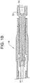
FIG. 1B depicts a cross-sectional view of a bearing assembly the downhole motor ofFIG. 1A , formed in accordance with an exemplary embodiment; -
FIG. 2 depicts an axial end view of the stator, in accordance with an aspect of an exemplary embodiment; -
FIG. 3 depicts an elevational view of a rotary system for making the composite metal housing, in accordance with an exemplary embodiment; -
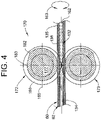
FIG. 4 depicts an elevational view of a rotary system for making the composite metal housing, in accordance with another aspect of an exemplary embodiment; -
FIG. 5 depicts an elevational view of a rotary system for making the composite metal housing, in accordance with yet another aspect of an exemplary embodiment; -
FIG. 6 depicts a swaging process for making the composite metal housing, in accordance with still yet another aspect of an exemplary embodiment; and -
FIG. 7 depicts a partial cut-away view of a metal housing formed in accordance with an aspect of an exemplary embodiment. - A downhole motor, in accordance with an exemplary embodiment, is illustrated generally at 10 in
FIGs. 1A and1B .Downhole motor 10 may take the form of a positive displacement motor, following the Moineau Principle, having a power section 12 (FIG. 1A ) operatively coupled to a bearing assembly 14 (FIG. 1B ). That is,downhole motor 10 may take the form of a Moineau system configured for use in a downhole environment.Power section 12 includes an elongatedcomposite metal housing 16 that defines astator 18. The term "composite" should be understood to describe thatstator 18 may be formed with multiple layers of material as will be detailed below.Stator 18 includes an interior 20 having a selected inner contour in the form of a helically lobedinner surface 22 that may be defined by anelastomeric layer 24 or by a pre-contoured metal housing. It is to be understood that in the case of a pre-contoured metal housing, helically lobedinner surface 22 may be covered by an elastomeric material, a non-elastomeric material, referred to as a lined stator, or remain uncovered depending upon operating conditions ofdownhole motor 10. -
Downhole motor 10 also includes arotor 28 arranged ininterior 20.Rotor 28 includes a helically lobedouter surface 30 that engages with helically lobedinner surface 22 ofstator 18. Helically lobedouter surface 30 includes one less lobe than helically lobedinner surface 22.Rotor 28 includes afirst end portion 32, asecond end portion 33, and anintermediate portion 34. - In operation,
rotor 28 with helically lobedouter surface 30 rotates withinstator 18 with helically lobedinner surface 22 to form a plurality of axial fluid chambers orcavities 40 which may be filled withpressurized drilling fluid 37 flowing through interior 20 in adirection 43 from anuphole end 44 toward adownhole end 46 ofstator 18.Bearing assembly 14 illustrated inFIG. 1B includes aflexible shaft 50 coupled to arotatable drive shaft 52 which carries abit box 54. It is to be understood that additional components (not shown) may be arranged betweenpower section 12 and bearingassembly 14.Bit box 54 may operatively connect to a drill bit (not shown). - In accordance with an exemplary aspect illustrated in
FIG. 2 ,composite metal housing 16 which definesstator 18 includes an outertubular member 60 formed from a first material (not separately labeled) operatively connected with an innertubular member 62 formed from a second material (also not separately labeled) that may be distinct from the first material. The term "composite" should be understood to describe thatstator 18 may be formed from multiple layers of material. Innertubular member 62 may be connected to outertubular member 60 through various processes as will be discussed more fully below. In accordance with an aspect of an exemplary embodiment, innertubular member 62 may extend an entire longitudinal length of outertubular member 60. However, it is to be understood that innertubular member 62 may extend over only a portion of outertubular member 60. Innertubular member 62 is shown to include the helically lobedinner surface 22. It should be understood however that helically lobedinner surface 22 may extend into outertubular member 60. - In accordance with an aspect of an exemplary embodiment, the first material forming outer
tubular member 60 includes selected material properties such as strength properties, chemical resistance, corrosion resistance, and/or brittleness, selected to support drilling loads and conditions associated with downhole environments. - In accordance with another aspect of an exemplary embodiment, the second material forming inner
tubular member 62 may be selected for other desirable material properties. For example, the second material may be selected to include particular surface properties with respect to mechanical, material and chemical properties, e.g. friction, roughness, hardness, and/or brittleness, heat conductivity, ductility, electrical conductivity, wear resistance and chemical resistance or chemical reactivity. For example, the second material may include a low coefficient of friction. The term "low coefficient of friction" should be understood to mean a material that allowsrotor 28 to rotate withinstator 18 with limited wear. The use of a low coefficient of friction material may preclude a need for an inner layer incomposite metal housing 16. - In another example, the second material may be selected for improved bonding properties with an elastomeric material if used for as an inner layer, a non-elastomeric material if used for an inner layer, or another material having other desirable properties. Examples of desirable materials for inner
tubular member 62 may include Copper and copper alloys, Molybdenum and Molybdenum alloys, Nickel and Nickel alloys, steel with various properties (corrosion resistive, hardenable, temperable), duplex steel, materials that are suitable for chemical and/or electro-chemical etching to create a specific surface roughness. In another example, the second material may be softer and more flowable in order to easier form lobes with high accuracy. - In accordance with an aspect of an exemplary embodiment, outer
tubular member 60 and innertubular member 62 may possess similar radial thicknesses. In accordance with another aspect of an exemplary embodiment, outertubular member 60 and innertubular member 62 may possess different radial thicknesses. In accordance with another aspect of an exemplary embodiment, outertubular member 60 may be formed with a radial thickness that is greater than a radial thickness of innertubular member 62. Conversely,inner tubular member 62 may be formed with a radial thickness that is greater than a radial thickness of outertubular member 60. - In accordance with another aspect of an exemplary embodiment, various methods may be used to position an inner layer (not shown) also referred to as a lining, or to finish
inner surface 22 of innertubular member 62 such as, for example, physical vapor deposition (PVD), chemical vapor deposition (CVD), injection molding, a plasma spray process, spray coating, chemical deposition, nitriding, carburizing, plasma polymer coating, nitro-carburizing, boriding/boronizing, thermo-set process, baking process, aging. Examples of desirable materials for inner layers may include elastomeric material, thermo-plastic material, metallic material, ceramic material, chrome, graphite, diamond-like carbon (DLC) and alternative suitable materials. - Reference will now follow to
FIGS. 3-6 in describing various processes for formingcomposite metal housing 16.FIG. 3 depicts a shortstroke rolling process 110. Outertubular member 60 is positioned aboutinner tubular member 62. Arigid mandrel 132 is arranged ininterior 20 of innertubular member 62. In accordance with an aspect of an exemplary embodiment,rigid mandrel 132 may take the form of a contour forming member.Rigid mandrel 132 includes afirst end 134, asecond end 135, and anintermediate portion 136.Intermediate portion 136 includes a contouredouter surface 138 defining a selected contour that corresponds to helically lobedinner surface 22. The particular shape, form, and/or overall geometry of contouredouter surface 138 may vary depending upon a desired shape, form, and/or geometry of helically lobedinner surface 22.Rigid mandrel 132 defines an axis ofrotation 139 forcomposite metal housing 16. - Inner and outer
tubular members first roller 140 and a second forced application member depicted as asecond roller 141. As eachroller roller 140 with an understanding thatroller 141 may include a similar structure.Roller 140 includes a roller die 143 that strokes or reciprocates over outertubular member 60 in a direction shown byarrow 145.Rollers tubular member 60 radially inwardly toward innertubular member 62. Both outer and innertubular members rigid mandrel 132 applying a compressive force. By way of non-limiting embodimentrigid mandrel 132 may be tapered fromfirst end 134 tosecond end 135 with the second end having an outer dimension (not separately labeled) that is less than an outer dimension (also not separately labeled) offirst end 134. The taper facilitates easy removal of therigid mandrel 132 fromcomposite metal housing 16. -
Roller 140 incudes acaliper section 148 that defines a travel depth of roller die 143 toward outertubular member 60 and innertubular member 62. Aclearance 150 between roller die 143 and anouter surface 153 or roller die 143 increases along astroke path 154 defined between afirst end section 155 and asecond end section 156. In operation,rollers tubular member 60 and reciprocate alongstroke path 154 along an axis ofmovement 160. Roller die 143 travels to greater depths alongstroke path 154 applying a compressive force. At the same time,composite metal housing 16 rotates about anaxis 162 as shown byarrow 163. As the process continues,inner tubular member 62 takes on a shape corresponding to contouredouter surface 138 ofrigid mandrel 132 forming helically lobedinner surface 22. In addition to forming helically lobedinner surface 22, compressive forces applied byrollers tubular member 60 onto innertubular member 62. In another embodimentrigid mandrel 132 may not have a contoured outer surface and may be used only to compress outertubular member 60 and innertubular member 62 without forming an inner contoured surface. - In accordance with another aspect of an exemplary embodiment, outer
tubular member 60 and/or innertubular member 62 may comprises multiple material layers that be connected through an application of compressional forces to formcomposite metal housing 16 ofstator 18. Alternatively, in other examples not falling under the scope of the claims, in lieu of compressive forces, other connecting methods such as adhesion, forging, cold welding, hot welding, chemical connection, a mechanical connection like a form fit, may be employed to join outertubular member 60 and innertubular member 62. The term "form fit" should be understood to describe an interlocking of at least two connecting partners. As a result, the connecting partners cannot detach themselves without or during intermittent force transmission. Thus, in the case of a form-fit or "form locking connection" of one connecting partner, the other connecting partner is in the way. Further, when applying compressive forces, heat may be applied to further enhance connecting characteristics (cold rolled) (hot rolled). Cold may be temperatures up to around 100 Centigrade, intermediate temperatures maybe from around 100 Centigrade to 600 Centigrade, hot temperatures may be from 900 Centigrade and above. - Reference will now follow to
FIG. 4 , wherein like reference numbers represent corresponding parts in the respective views in describing a longstroke rolling process 170 employing a first force application member shown as afirst roller 172 and a second force application member shown as asecond roller 173. As eachroller roller 172 with an understanding thatroller 173 may include similar structure.Roller 172 includes a roller die 177 having astroke path 180 that is longer than stroke path 154 (FIG. 3 ).Stroke path 180 extends between afirst end 182 and asecond end 183. - In operation, two rollers, e.g.,
rollers tubular member 60 applying a compressive force and reciprocate alongstroke path 180 along an axis ofmovement 185. Roller 177 travels to greater depths alongstroke path 180. At the same time, composite metal housing 16 (FIG. 2 ) rotates aboutaxis 162 as shown byarrow 163 inFIG. 4 . As the process continues,inner tubular member 62 takes on a shape corresponding to contouredouter surface 138 ofrigid mandrel 132 forming helically lobed inner surface 22 (FIG. 1A ). In addition to forming helically lobedinner surface 22, compressive forces applied byrollers tubular member 60 onto innertubular member 62. - Reference will now follow to
FIG. 5 , wherein like reference numbers represent corresponding parts in the respective views in describing arolling process 190 employing a first force application member shown as afirst roller 192, a second force application member shown as asecond roller 193, and a third force application member shown as athird roller 194 which rotate about a corresponding central axis (not separately labeled) in a direction identified byarrows 196a-196c. Arigid mandrel 200 having a contouredouter surface 202 is arranged in interior (not separately labeled) of innertubular member 62. In operation, rollers 192-194 rotate and are urged radially inwardly in a direction identified byarrows 206a-206c applying a compressive force to outertubular member 60 and innertubular member 62. At the same time, outer andinner tubulars members arrow 209 opposite first, second, andthird rollers inner tubular member 62 takes on a shape corresponding to contouredouter surface 202 ofrigid mandrel 200 forming helically lobedinner surface 22. In addition to forming helically lobedinner surface 22, compressive forces applied by rollers 192-194 compress outertubular member 60 onto innertubular member 62. - Reference will now follow to
FIG. 6 wherein like reference numbers represent corresponding parts in the respective views in describing arotary swaging process 212.Rotary swaging process 212 employs a plurality of force application members shown in the form of swaging devices or conformingblocks tubular member 60 and innertubular member 62. Each conformingblock 214a-214d includes a corresponding concaveinner surface 216a-216d. Conformingblocks 214a-214d are urged radially inwardly in a direction identified by correspondingarrows 218a-218d applying a compressive force to outertubular member 60 and innertubular member 62. Arigid mandrel 224 having a contouredouter surface 226 is arranged withininterior 20 of innertubular member 62. - In operation, conforming
blocks 214a-214d are urged radially inwardly. At the same time, outer andinner tubulars composite metal housing 16 rotate in a direction identified byarrow 228. As the process continues,inner tubular member 62 takes on a shape corresponding to contouredouter surface 226 ofrigid mandrel 224 forming helically lobedinner surface 22 such as shown inFIG. 2 . In addition to forming helically lobedinner surface 22, compressive forces applied by conformingblocks 214a-214d force outertubular member 60 onto innertubular member 62 forming a connection. - Once
composite metal housing 16 of stator 18 (FIG. 1A ) is formed, one or more channels, one of which is indicated at 250 inFIG. 7 may be formed in helically lobedinner surface 22.Channels 250 may promote cooling ofdownhole motor 10. Additionally, it is understood thatcomposite metal housing 16 formingstator 18 may include one or more channels and/or passages that may serve as conduits for electrical cabling, hydraulic lines, and the like.Channels 250 may be achieved by placing a third material which could take the form of a massive material (not shown) in between outertubular member 60 and innertubular member 62 prior to forming helically lobedinner surface 22. The massive material may later be dissolved by one of a variety of known processes such as by heating, etching, applying a chemical, a subtractive a machining method or the like such as shown inFIG. 7 . By non-limiting example the massive material may take the form of a round bar member, a non-round bar member, a folded bar member and/or a non-folded bar member. - It is also to be understood that
composite metal housing 16 formingstator 18 may be formed by any of the above described methods and/or other suitable processes. The use of different materials to formcomposite metal housing 16 provides better strength characteristics as well as enhances wear and corrosion resistance. For example, outertubular member 60 may be formed from a first material having desired strength characteristics while innertubular member 62 may be formed from a second material suitable for a selected forming operation. The second material may also be selected for desired finishing characteristics including hard facing, corrosion protection without compromising other desired properties such as strength and formability. - It should be understood that additional layers (not shown) may exist between outer
tubular member 60 and innertubular member 62 that promote connecting inner and outer tubulars and/or provide a desired heat barrier, electrical insulating layer, material diffusion layer, or the like. Such an intermediate layer may cover all or a portion of the inner surface of outertubular member 60. Further, it is to be understood that outertubular member 60 may be pre-contoured. - Although, the method described herein is employed to form a stator of a progressive cavity motor, the method may also be employed to form other stators, such as a stator for a progressive cavity pump following the Moineau principle.
Claims (15)
- A method of making a stator (18) comprising:positioning an inner tubular member (62) having an inner surface (22) within an outer tubular member (60);and installing a rigid mandrel (132) within the inner tubular member (62);the method characterised by applying a compressive force to the inner tubular member (62) and the outer tubular member (60), the compressive force causing the inner tubular member to be connected to the outer tubular member.
- The method of claim 1, wherein both the inner tubular member (62) and the outer tubular member (60) comprise metallic materials.
- The method of claim 1, wherein positioning the inner tubular member (62) within the outer tubular member (60) includes positioning an inner tubular member (62) formed from a first material in an outer tubular member (60) formed from a second material that is distinct from the first material.
- The method of claim 3, wherein the first material is more pliable than the second material.
- The method of claim 3, further comprising:positioning a third material between the inner tubular member (62) and the outer tubular member (60); andforming, with the third material, one or more channels (250) between the inner tubular member (62) and the outer tubular member (60).
- The method of claim 1, wherein installing the rigid mandrel (132) includes installing a member having a selected contour within the inner tubular member (62).
- The method of claim 6, wherein applying the compressive force includes forming the selected contour on the inner surface (22) of the inner tubular member (62).
- The method of claim 7, further comprising: positioning an inner layer on the selected contour formed on the inner surface (22) of the inner tubular member (62), optionally wherein positioning the inner layer includes bonding the inner layer to the selected contour.
- The method of claim 1, wherein applying the compressive force includes compressing the outer tubular member (60) between at least two rollers (140).
- The method of claim 9, wherein compressing the outer tubular member (60) between at least two rollers (140) includes shifting the rollers (140) along the outer tubular member (60).
- A downhole motor comprising a stator formed by the method of claim 1 configured for use in a downhole environment wherein:the inner tubular member (62) comprising a first metallic material having an outer surface (30) and a helically lobed inner surface (22) integrally formed with the inner tubular member (62); andthe outer tubular member (60) comprising a second metallic material that is different from the first metallic material, the inner tubular member (62) and the outer tubular member (60) forming a stator (18) of a Moineau system.
- The downhole motor according to claim 11, wherein the first metallic material is more pliable than the second metallic material.
- The downhole motor according to claim 11, further comprising: one or more channels extending between the inner tubular member and the outer tubular member.
- The downhole motor according to claim 11, further comprising: an inner layer provided on the helically lobed inner surface.
- The downhole motor according to claim 14, wherein the inner layer comprises an elastomeric material.
Applications Claiming Priority (2)
| Application Number | Priority Date | Filing Date | Title |
|---|---|---|---|
| US15/437,612 US10920493B2 (en) | 2017-02-21 | 2017-02-21 | Method of forming stators for downhole motors |
| PCT/US2018/018292 WO2018156411A1 (en) | 2017-02-21 | 2018-02-15 | Method of forming stators for downhole motors |
Publications (3)
| Publication Number | Publication Date |
|---|---|
| EP3586432A1 EP3586432A1 (en) | 2020-01-01 |
| EP3586432A4 EP3586432A4 (en) | 2020-11-25 |
| EP3586432B1 true EP3586432B1 (en) | 2022-10-26 |
Family
ID=63166476
Family Applications (1)
| Application Number | Title | Priority Date | Filing Date |
|---|---|---|---|
| EP18758288.7A Active EP3586432B1 (en) | 2017-02-21 | 2018-02-15 | Method of forming stators for downhole motors |
Country Status (6)
| Country | Link |
|---|---|
| US (2) | US10920493B2 (en) |
| EP (1) | EP3586432B1 (en) |
| CN (1) | CN110326196B (en) |
| CA (1) | CA3053778C (en) |
| RU (1) | RU2723681C1 (en) |
| WO (1) | WO2018156411A1 (en) |
Families Citing this family (10)
| Publication number | Priority date | Publication date | Assignee | Title |
|---|---|---|---|---|
| US10920493B2 (en) * | 2017-02-21 | 2021-02-16 | Baker Hughes, A Ge Company, Llc | Method of forming stators for downhole motors |
| US11225837B2 (en) * | 2019-12-31 | 2022-01-18 | Cnpc Chuanqing Drilling Engineering Company Limited | Dual-speed dual—core enhanced drilling equipment |
| EP4171934A4 (en) | 2020-06-30 | 2024-07-31 | Services Pétroliers Schlumberger | Over mandrel extrusion for composite pcp stator |
| WO2022026572A1 (en) | 2020-07-31 | 2022-02-03 | Baker Hughes Oilfield Operations Llc | Metal felt and brush structures as sealing elements in metal-metal mud motors |
| WO2023129130A1 (en) * | 2021-12-28 | 2023-07-06 | Halliburton Energy Services, Inc. | Cold spraying a coating onto a rotor in a downhole motor assembly |
| EP4587682A4 (en) * | 2022-10-12 | 2025-08-06 | Services Petroliers Schlumberger | PUMP STATOR BINDING LAYER |
| CN116201728B (en) * | 2022-12-22 | 2024-02-13 | 华创机器人制造有限公司 | Special screw pump for submersible screw pump oil extraction machine and manufacturing method |
| WO2024147932A1 (en) * | 2023-01-03 | 2024-07-11 | Schlumberger Technology Corporation | Anisotropic stator reinforcement lining |
| WO2024147933A1 (en) * | 2023-01-03 | 2024-07-11 | Schlumberger Technology Corporation | Intervening reinforcement lining for a mud motor |
| US20260062999A1 (en) * | 2024-08-28 | 2026-03-05 | Thru Tubing Solutions, Inc. | Downhole fluid motor and associated methods |
Family Cites Families (20)
| Publication number | Priority date | Publication date | Assignee | Title |
|---|---|---|---|---|
| US6461128B2 (en) | 1996-04-24 | 2002-10-08 | Steven M. Wood | Progressive cavity helical device |
| CN2339741Y (en) * | 1997-11-15 | 1999-09-22 | 符达良 | Long-service-life turbine driller without rubber elements |
| EP1040275B1 (en) | 1997-12-18 | 2003-09-10 | Baker Hughes Incorporated | Method of making stators for moineau pumps |
| FR2826407B1 (en) * | 2001-06-21 | 2004-04-16 | Pcm Pompes | SPRAY PUMP STATOR AND PROCESS FOR ITS MANUFACTURE |
| US6881045B2 (en) | 2003-06-19 | 2005-04-19 | Robbins & Myers Energy Systems, L.P. | Progressive cavity pump/motor |
| US7517202B2 (en) | 2005-01-12 | 2009-04-14 | Smith International, Inc. | Multiple elastomer layer progressing cavity stators |
| US7312544B2 (en) * | 2005-02-15 | 2007-12-25 | General Electric Company | Fluid transfer device and method for conveying fluid to a rotating member |
| CA2673720C (en) * | 2007-01-24 | 2013-04-16 | Halliburton Energy Services, Inc. | Electroformed stator tube for a progressing cavity apparatus |
| CN101307674B (en) * | 2007-05-14 | 2010-12-15 | 伍成林 | Long life spiral transduction apparatus |
| US7950914B2 (en) * | 2007-06-05 | 2011-05-31 | Smith International, Inc. | Braze or solder reinforced Moineau stator |
| US8197241B2 (en) * | 2007-12-18 | 2012-06-12 | Schlumberger Technology Corporation | Nanocomposite Moineau device |
| US20100038142A1 (en) * | 2007-12-18 | 2010-02-18 | Halliburton Energy Services, Inc. | Apparatus and method for high temperature drilling operations |
| US7941906B2 (en) * | 2007-12-31 | 2011-05-17 | Schlumberger Technology Corporation | Progressive cavity apparatus with transducer and methods of forming and use |
| US20110116961A1 (en) * | 2009-11-13 | 2011-05-19 | Hossein Akbari | Stators for downhole motors, methods for fabricating the same, and downhole motors incorporating the same |
| CN102447363A (en) * | 2010-09-30 | 2012-05-09 | 艾默生电气公司 | Line-start permanent-magnet brushless motor with aluminum windings |
| JP2013167415A (en) * | 2012-02-16 | 2013-08-29 | Kawasaki New Energy Manufacturing Co Ltd | Stirling cycle engine |
| KR101422483B1 (en) | 2012-12-21 | 2014-07-23 | 삼성중공업 주식회사 | Method for mining high viscosity oil |
| US9112398B2 (en) * | 2013-06-25 | 2015-08-18 | Baker Hughes Incorporated | Nitrogen- and ceramic-surface-treated components for downhole motors and related methods |
| GB2542003B (en) * | 2014-06-27 | 2020-12-16 | Halliburton Energy Services Inc | Measuring micro stalls and stick slips in mud motors using fiber optic sensors |
| US10920493B2 (en) | 2017-02-21 | 2021-02-16 | Baker Hughes, A Ge Company, Llc | Method of forming stators for downhole motors |
-
2017
- 2017-02-21 US US15/437,612 patent/US10920493B2/en active Active
-
2018
- 2018-02-15 CA CA3053778A patent/CA3053778C/en active Active
- 2018-02-15 CN CN201880013126.9A patent/CN110326196B/en active Active
- 2018-02-15 RU RU2019126679A patent/RU2723681C1/en active
- 2018-02-15 WO PCT/US2018/018292 patent/WO2018156411A1/en not_active Ceased
- 2018-02-15 EP EP18758288.7A patent/EP3586432B1/en active Active
-
2021
- 2021-01-06 US US17/142,519 patent/US11319753B2/en active Active
Also Published As
| Publication number | Publication date |
|---|---|
| WO2018156411A1 (en) | 2018-08-30 |
| US20180238114A1 (en) | 2018-08-23 |
| CA3053778C (en) | 2023-01-17 |
| CA3053778A1 (en) | 2018-08-30 |
| CN110326196B (en) | 2021-06-18 |
| EP3586432A4 (en) | 2020-11-25 |
| US10920493B2 (en) | 2021-02-16 |
| CN110326196A (en) | 2019-10-11 |
| EP3586432A1 (en) | 2020-01-01 |
| RU2723681C1 (en) | 2020-06-17 |
| US20210148171A1 (en) | 2021-05-20 |
| US11319753B2 (en) | 2022-05-03 |
Similar Documents
| Publication | Publication Date | Title |
|---|---|---|
| US11319753B2 (en) | Method of forming stators for downhole motors | |
| US6543132B1 (en) | Methods of making mud motors | |
| EP1095218B1 (en) | Internally profiled stator tube | |
| CN103890304B (en) | Downhole motors and pumps with asymmetric lobes | |
| EP1333151A2 (en) | Liner of optimized thickness for positive displacement drilling motors | |
| US9393648B2 (en) | Undercut stator for a positive displacment motor | |
| US9909365B2 (en) | Downhole tools having mechanical joints with enhanced surfaces | |
| EP3066287B1 (en) | Hydraulic tools, drilling systems including hydraulic tools, and methods of using hydraulic tools | |
| US8776916B2 (en) | Drilling motors with elastically deformable lobes | |
| JP7714815B2 (en) | Hard seal ring with sliding surface, sliding seal device and manufacturing method | |
| US20100006342A1 (en) | Method of making wellbore moineau devices | |
| US11739592B2 (en) | Downhole motor or pump with stator manufactured with cold spray | |
| CA2409054C (en) | Method of forming a moineau stator and a moineau stator | |
| US20260063000A1 (en) | Progressive cavity assembly and associated methods | |
| EP3499038B1 (en) | Stator and rotor profile for improved power section performance and reliability | |
| US20260071621A1 (en) | Progressive cavity fluid pump and associated methods | |
| US20260062999A1 (en) | Downhole fluid motor and associated methods | |
| CA3283445A1 (en) | Downhole fluid motor and associated methods |
Legal Events
| Date | Code | Title | Description |
|---|---|---|---|
| STAA | Information on the status of an ep patent application or granted ep patent |
Free format text: STATUS: THE INTERNATIONAL PUBLICATION HAS BEEN MADE |
|
| PUAI | Public reference made under article 153(3) epc to a published international application that has entered the european phase |
Free format text: ORIGINAL CODE: 0009012 |
|
| STAA | Information on the status of an ep patent application or granted ep patent |
Free format text: STATUS: REQUEST FOR EXAMINATION WAS MADE |
|
| 17P | Request for examination filed |
Effective date: 20190919 |
|
| AK | Designated contracting states |
Kind code of ref document: A1 Designated state(s): AL AT BE BG CH CY CZ DE DK EE ES FI FR GB GR HR HU IE IS IT LI LT LU LV MC MK MT NL NO PL PT RO RS SE SI SK SM TR |
|
| AX | Request for extension of the european patent |
Extension state: BA ME |
|
| DAV | Request for validation of the european patent (deleted) | ||
| DAX | Request for extension of the european patent (deleted) | ||
| A4 | Supplementary search report drawn up and despatched |
Effective date: 20201026 |
|
| RIC1 | Information provided on ipc code assigned before grant |
Ipc: H02K 15/02 20060101AFI20201020BHEP |
|
| GRAP | Despatch of communication of intention to grant a patent |
Free format text: ORIGINAL CODE: EPIDOSNIGR1 |
|
| STAA | Information on the status of an ep patent application or granted ep patent |
Free format text: STATUS: GRANT OF PATENT IS INTENDED |
|
| INTG | Intention to grant announced |
Effective date: 20211029 |
|
| GRAJ | Information related to disapproval of communication of intention to grant by the applicant or resumption of examination proceedings by the epo deleted |
Free format text: ORIGINAL CODE: EPIDOSDIGR1 |
|
| STAA | Information on the status of an ep patent application or granted ep patent |
Free format text: STATUS: REQUEST FOR EXAMINATION WAS MADE |
|
| INTC | Intention to grant announced (deleted) | ||
| GRAP | Despatch of communication of intention to grant a patent |
Free format text: ORIGINAL CODE: EPIDOSNIGR1 |
|
| STAA | Information on the status of an ep patent application or granted ep patent |
Free format text: STATUS: GRANT OF PATENT IS INTENDED |
|
| INTG | Intention to grant announced |
Effective date: 20220425 |
|
| GRAS | Grant fee paid |
Free format text: ORIGINAL CODE: EPIDOSNIGR3 |
|
| GRAA | (expected) grant |
Free format text: ORIGINAL CODE: 0009210 |
|
| STAA | Information on the status of an ep patent application or granted ep patent |
Free format text: STATUS: THE PATENT HAS BEEN GRANTED |
|
| RAP3 | Party data changed (applicant data changed or rights of an application transferred) |
Owner name: BAKER HUGHES HOLDINGS LLC |
|
| AK | Designated contracting states |
Kind code of ref document: B1 Designated state(s): AL AT BE BG CH CY CZ DE DK EE ES FI FR GB GR HR HU IE IS IT LI LT LU LV MC MK MT NL NO PL PT RO RS SE SI SK SM TR |
|
| REG | Reference to a national code |
Ref country code: GB Ref legal event code: FG4D |
|
| REG | Reference to a national code |
Ref country code: CH Ref legal event code: EP |
|
| REG | Reference to a national code |
Ref country code: AT Ref legal event code: REF Ref document number: 1527789 Country of ref document: AT Kind code of ref document: T Effective date: 20221115 |
|
| REG | Reference to a national code |
Ref country code: DE Ref legal event code: R096 Ref document number: 602018042274 Country of ref document: DE |
|
| REG | Reference to a national code |
Ref country code: IE Ref legal event code: FG4D |
|
| REG | Reference to a national code |
Ref country code: NO Ref legal event code: T2 Effective date: 20221026 |
|
| REG | Reference to a national code |
Ref country code: LT Ref legal event code: MG9D |
|
| REG | Reference to a national code |
Ref country code: NL Ref legal event code: MP Effective date: 20221026 |
|
| REG | Reference to a national code |
Ref country code: AT Ref legal event code: MK05 Ref document number: 1527789 Country of ref document: AT Kind code of ref document: T Effective date: 20221026 |
|
| PG25 | Lapsed in a contracting state [announced via postgrant information from national office to epo] |
Ref country code: NL Free format text: LAPSE BECAUSE OF FAILURE TO SUBMIT A TRANSLATION OF THE DESCRIPTION OR TO PAY THE FEE WITHIN THE PRESCRIBED TIME-LIMIT Effective date: 20221026 |
|
| PG25 | Lapsed in a contracting state [announced via postgrant information from national office to epo] |
Ref country code: SE Free format text: LAPSE BECAUSE OF FAILURE TO SUBMIT A TRANSLATION OF THE DESCRIPTION OR TO PAY THE FEE WITHIN THE PRESCRIBED TIME-LIMIT Effective date: 20221026 Ref country code: PT Free format text: LAPSE BECAUSE OF FAILURE TO SUBMIT A TRANSLATION OF THE DESCRIPTION OR TO PAY THE FEE WITHIN THE PRESCRIBED TIME-LIMIT Effective date: 20230227 Ref country code: LT Free format text: LAPSE BECAUSE OF FAILURE TO SUBMIT A TRANSLATION OF THE DESCRIPTION OR TO PAY THE FEE WITHIN THE PRESCRIBED TIME-LIMIT Effective date: 20221026 Ref country code: FI Free format text: LAPSE BECAUSE OF FAILURE TO SUBMIT A TRANSLATION OF THE DESCRIPTION OR TO PAY THE FEE WITHIN THE PRESCRIBED TIME-LIMIT Effective date: 20221026 Ref country code: ES Free format text: LAPSE BECAUSE OF FAILURE TO SUBMIT A TRANSLATION OF THE DESCRIPTION OR TO PAY THE FEE WITHIN THE PRESCRIBED TIME-LIMIT Effective date: 20221026 Ref country code: AT Free format text: LAPSE BECAUSE OF FAILURE TO SUBMIT A TRANSLATION OF THE DESCRIPTION OR TO PAY THE FEE WITHIN THE PRESCRIBED TIME-LIMIT Effective date: 20221026 |
|
| PG25 | Lapsed in a contracting state [announced via postgrant information from national office to epo] |
Ref country code: RS Free format text: LAPSE BECAUSE OF FAILURE TO SUBMIT A TRANSLATION OF THE DESCRIPTION OR TO PAY THE FEE WITHIN THE PRESCRIBED TIME-LIMIT Effective date: 20221026 Ref country code: PL Free format text: LAPSE BECAUSE OF FAILURE TO SUBMIT A TRANSLATION OF THE DESCRIPTION OR TO PAY THE FEE WITHIN THE PRESCRIBED TIME-LIMIT Effective date: 20221026 Ref country code: LV Free format text: LAPSE BECAUSE OF FAILURE TO SUBMIT A TRANSLATION OF THE DESCRIPTION OR TO PAY THE FEE WITHIN THE PRESCRIBED TIME-LIMIT Effective date: 20221026 Ref country code: IS Free format text: LAPSE BECAUSE OF FAILURE TO SUBMIT A TRANSLATION OF THE DESCRIPTION OR TO PAY THE FEE WITHIN THE PRESCRIBED TIME-LIMIT Effective date: 20230226 Ref country code: HR Free format text: LAPSE BECAUSE OF FAILURE TO SUBMIT A TRANSLATION OF THE DESCRIPTION OR TO PAY THE FEE WITHIN THE PRESCRIBED TIME-LIMIT Effective date: 20221026 Ref country code: GR Free format text: LAPSE BECAUSE OF FAILURE TO SUBMIT A TRANSLATION OF THE DESCRIPTION OR TO PAY THE FEE WITHIN THE PRESCRIBED TIME-LIMIT Effective date: 20230127 |
|
| P01 | Opt-out of the competence of the unified patent court (upc) registered |
Effective date: 20230526 |
|
| REG | Reference to a national code |
Ref country code: DE Ref legal event code: R097 Ref document number: 602018042274 Country of ref document: DE |
|
| PG25 | Lapsed in a contracting state [announced via postgrant information from national office to epo] |
Ref country code: SM Free format text: LAPSE BECAUSE OF FAILURE TO SUBMIT A TRANSLATION OF THE DESCRIPTION OR TO PAY THE FEE WITHIN THE PRESCRIBED TIME-LIMIT Effective date: 20221026 Ref country code: RO Free format text: LAPSE BECAUSE OF FAILURE TO SUBMIT A TRANSLATION OF THE DESCRIPTION OR TO PAY THE FEE WITHIN THE PRESCRIBED TIME-LIMIT Effective date: 20221026 Ref country code: EE Free format text: LAPSE BECAUSE OF FAILURE TO SUBMIT A TRANSLATION OF THE DESCRIPTION OR TO PAY THE FEE WITHIN THE PRESCRIBED TIME-LIMIT Effective date: 20221026 Ref country code: DK Free format text: LAPSE BECAUSE OF FAILURE TO SUBMIT A TRANSLATION OF THE DESCRIPTION OR TO PAY THE FEE WITHIN THE PRESCRIBED TIME-LIMIT Effective date: 20221026 Ref country code: CZ Free format text: LAPSE BECAUSE OF FAILURE TO SUBMIT A TRANSLATION OF THE DESCRIPTION OR TO PAY THE FEE WITHIN THE PRESCRIBED TIME-LIMIT Effective date: 20221026 |
|
| PG25 | Lapsed in a contracting state [announced via postgrant information from national office to epo] |
Ref country code: SK Free format text: LAPSE BECAUSE OF FAILURE TO SUBMIT A TRANSLATION OF THE DESCRIPTION OR TO PAY THE FEE WITHIN THE PRESCRIBED TIME-LIMIT Effective date: 20221026 Ref country code: AL Free format text: LAPSE BECAUSE OF FAILURE TO SUBMIT A TRANSLATION OF THE DESCRIPTION OR TO PAY THE FEE WITHIN THE PRESCRIBED TIME-LIMIT Effective date: 20221026 |
|
| PLBE | No opposition filed within time limit |
Free format text: ORIGINAL CODE: 0009261 |
|
| REG | Reference to a national code |
Ref country code: DE Ref legal event code: R119 Ref document number: 602018042274 Country of ref document: DE |
|
| STAA | Information on the status of an ep patent application or granted ep patent |
Free format text: STATUS: NO OPPOSITION FILED WITHIN TIME LIMIT |
|
| PG25 | Lapsed in a contracting state [announced via postgrant information from national office to epo] |
Ref country code: MC Free format text: LAPSE BECAUSE OF FAILURE TO SUBMIT A TRANSLATION OF THE DESCRIPTION OR TO PAY THE FEE WITHIN THE PRESCRIBED TIME-LIMIT Effective date: 20221026 |
|
| REG | Reference to a national code |
Ref country code: CH Ref legal event code: PL |
|
| 26N | No opposition filed |
Effective date: 20230727 |
|
| REG | Reference to a national code |
Ref country code: BE Ref legal event code: MM Effective date: 20230228 |
|
| PG25 | Lapsed in a contracting state [announced via postgrant information from national office to epo] |
Ref country code: LU Free format text: LAPSE BECAUSE OF NON-PAYMENT OF DUE FEES Effective date: 20230215 Ref country code: LI Free format text: LAPSE BECAUSE OF NON-PAYMENT OF DUE FEES Effective date: 20230228 Ref country code: CH Free format text: LAPSE BECAUSE OF NON-PAYMENT OF DUE FEES Effective date: 20230228 |
|
| PG25 | Lapsed in a contracting state [announced via postgrant information from national office to epo] |
Ref country code: SI Free format text: LAPSE BECAUSE OF FAILURE TO SUBMIT A TRANSLATION OF THE DESCRIPTION OR TO PAY THE FEE WITHIN THE PRESCRIBED TIME-LIMIT Effective date: 20221026 |
|
| REG | Reference to a national code |
Ref country code: IE Ref legal event code: MM4A |
|
| PG25 | Lapsed in a contracting state [announced via postgrant information from national office to epo] |
Ref country code: IE Free format text: LAPSE BECAUSE OF NON-PAYMENT OF DUE FEES Effective date: 20230215 Ref country code: FR Free format text: LAPSE BECAUSE OF NON-PAYMENT OF DUE FEES Effective date: 20230228 Ref country code: DE Free format text: LAPSE BECAUSE OF NON-PAYMENT OF DUE FEES Effective date: 20230901 |
|
| PG25 | Lapsed in a contracting state [announced via postgrant information from national office to epo] |
Ref country code: BE Free format text: LAPSE BECAUSE OF NON-PAYMENT OF DUE FEES Effective date: 20230228 |
|
| PG25 | Lapsed in a contracting state [announced via postgrant information from national office to epo] |
Ref country code: IT Free format text: LAPSE BECAUSE OF FAILURE TO SUBMIT A TRANSLATION OF THE DESCRIPTION OR TO PAY THE FEE WITHIN THE PRESCRIBED TIME-LIMIT Effective date: 20221026 |
|
| PG25 | Lapsed in a contracting state [announced via postgrant information from national office to epo] |
Ref country code: BG Free format text: LAPSE BECAUSE OF FAILURE TO SUBMIT A TRANSLATION OF THE DESCRIPTION OR TO PAY THE FEE WITHIN THE PRESCRIBED TIME-LIMIT Effective date: 20221026 |
|
| PG25 | Lapsed in a contracting state [announced via postgrant information from national office to epo] |
Ref country code: BG Free format text: LAPSE BECAUSE OF FAILURE TO SUBMIT A TRANSLATION OF THE DESCRIPTION OR TO PAY THE FEE WITHIN THE PRESCRIBED TIME-LIMIT Effective date: 20221026 |
|
| PG25 | Lapsed in a contracting state [announced via postgrant information from national office to epo] |
Ref country code: CY Free format text: LAPSE BECAUSE OF FAILURE TO SUBMIT A TRANSLATION OF THE DESCRIPTION OR TO PAY THE FEE WITHIN THE PRESCRIBED TIME-LIMIT; INVALID AB INITIO Effective date: 20180215 |
|
| PG25 | Lapsed in a contracting state [announced via postgrant information from national office to epo] |
Ref country code: HU Free format text: LAPSE BECAUSE OF FAILURE TO SUBMIT A TRANSLATION OF THE DESCRIPTION OR TO PAY THE FEE WITHIN THE PRESCRIBED TIME-LIMIT; INVALID AB INITIO Effective date: 20180215 |
|
| PG25 | Lapsed in a contracting state [announced via postgrant information from national office to epo] |
Ref country code: TR Free format text: LAPSE BECAUSE OF FAILURE TO SUBMIT A TRANSLATION OF THE DESCRIPTION OR TO PAY THE FEE WITHIN THE PRESCRIBED TIME-LIMIT Effective date: 20221026 |
|
| PGFP | Annual fee paid to national office [announced via postgrant information from national office to epo] |
Ref country code: GB Payment date: 20260122 Year of fee payment: 9 |
|
| PGFP | Annual fee paid to national office [announced via postgrant information from national office to epo] |
Ref country code: NO Payment date: 20260123 Year of fee payment: 9 |