EP3586149B1 - Pump assembly having a controller including a circuit board and 3d rotary sensor for detecting rotation of its pump - Google Patents
Pump assembly having a controller including a circuit board and 3d rotary sensor for detecting rotation of its pump Download PDFInfo
- Publication number
- EP3586149B1 EP3586149B1 EP18758395.0A EP18758395A EP3586149B1 EP 3586149 B1 EP3586149 B1 EP 3586149B1 EP 18758395 A EP18758395 A EP 18758395A EP 3586149 B1 EP3586149 B1 EP 3586149B1
- Authority
- EP
- European Patent Office
- Prior art keywords
- pump
- drive shaft
- electric motor
- controller
- rotary sensor
- Prior art date
- Legal status (The legal status is an assumption and is not a legal conclusion. Google has not performed a legal analysis and makes no representation as to the accuracy of the status listed.)
- Active
Links
Images



Classifications
-
- F—MECHANICAL ENGINEERING; LIGHTING; HEATING; WEAPONS; BLASTING
- F04—POSITIVE - DISPLACEMENT MACHINES FOR LIQUIDS; PUMPS FOR LIQUIDS OR ELASTIC FLUIDS
- F04C—ROTARY-PISTON, OR OSCILLATING-PISTON, POSITIVE-DISPLACEMENT MACHINES FOR LIQUIDS; ROTARY-PISTON, OR OSCILLATING-PISTON, POSITIVE-DISPLACEMENT PUMPS
- F04C14/00—Control of, monitoring of, or safety arrangements for, machines, pumps or pumping installations
- F04C14/08—Control of, monitoring of, or safety arrangements for, machines, pumps or pumping installations characterised by varying the rotational speed
-
- G—PHYSICS
- G01—MEASURING; TESTING
- G01P—MEASURING LINEAR OR ANGULAR SPEED, ACCELERATION, DECELERATION, OR SHOCK; INDICATING PRESENCE, ABSENCE, OR DIRECTION, OF MOVEMENT
- G01P3/00—Measuring linear or angular speed; Measuring differences of linear or angular speeds
- G01P3/42—Devices characterised by the use of electric or magnetic means
- G01P3/44—Devices characterised by the use of electric or magnetic means for measuring angular speed
- G01P3/48—Devices characterised by the use of electric or magnetic means for measuring angular speed by measuring frequency of generated current or voltage
- G01P3/481—Devices characterised by the use of electric or magnetic means for measuring angular speed by measuring frequency of generated current or voltage of pulse signals
- G01P3/487—Devices characterised by the use of electric or magnetic means for measuring angular speed by measuring frequency of generated current or voltage of pulse signals delivered by rotating magnets
-
- F—MECHANICAL ENGINEERING; LIGHTING; HEATING; WEAPONS; BLASTING
- F04—POSITIVE - DISPLACEMENT MACHINES FOR LIQUIDS; PUMPS FOR LIQUIDS OR ELASTIC FLUIDS
- F04B—POSITIVE-DISPLACEMENT MACHINES FOR LIQUIDS; PUMPS
- F04B49/00—Control, e.g. of pump delivery, or pump pressure of, or safety measures for, machines, pumps, or pumping installations, not otherwise provided for, or of interest apart from, groups F04B1/00 - F04B47/00
- F04B49/06—Control using electricity
-
- F—MECHANICAL ENGINEERING; LIGHTING; HEATING; WEAPONS; BLASTING
- F04—POSITIVE - DISPLACEMENT MACHINES FOR LIQUIDS; PUMPS FOR LIQUIDS OR ELASTIC FLUIDS
- F04B—POSITIVE-DISPLACEMENT MACHINES FOR LIQUIDS; PUMPS
- F04B49/00—Control, e.g. of pump delivery, or pump pressure of, or safety measures for, machines, pumps, or pumping installations, not otherwise provided for, or of interest apart from, groups F04B1/00 - F04B47/00
- F04B49/20—Control, e.g. of pump delivery, or pump pressure of, or safety measures for, machines, pumps, or pumping installations, not otherwise provided for, or of interest apart from, groups F04B1/00 - F04B47/00 by changing the driving speed
-
- F—MECHANICAL ENGINEERING; LIGHTING; HEATING; WEAPONS; BLASTING
- F04—POSITIVE - DISPLACEMENT MACHINES FOR LIQUIDS; PUMPS FOR LIQUIDS OR ELASTIC FLUIDS
- F04C—ROTARY-PISTON, OR OSCILLATING-PISTON, POSITIVE-DISPLACEMENT MACHINES FOR LIQUIDS; ROTARY-PISTON, OR OSCILLATING-PISTON, POSITIVE-DISPLACEMENT PUMPS
- F04C15/00—Component parts, details or accessories of machines, pumps or pumping installations, not provided for in groups F04C2/00 - F04C14/00
- F04C15/0057—Driving elements, brakes, couplings, transmission specially adapted for machines or pumps
- F04C15/008—Prime movers
-
- F—MECHANICAL ENGINEERING; LIGHTING; HEATING; WEAPONS; BLASTING
- F04—POSITIVE - DISPLACEMENT MACHINES FOR LIQUIDS; PUMPS FOR LIQUIDS OR ELASTIC FLUIDS
- F04C—ROTARY-PISTON, OR OSCILLATING-PISTON, POSITIVE-DISPLACEMENT MACHINES FOR LIQUIDS; ROTARY-PISTON, OR OSCILLATING-PISTON, POSITIVE-DISPLACEMENT PUMPS
- F04C2/00—Rotary-piston machines or pumps
- F04C2/08—Rotary-piston machines or pumps of intermeshing-engagement type, i.e. with engagement of co-operating members similar to that of toothed gearing
- F04C2/10—Rotary-piston machines or pumps of intermeshing-engagement type, i.e. with engagement of co-operating members similar to that of toothed gearing of internal-axis type with the outer member having more teeth or tooth-equivalents, e.g. rollers, than the inner member
- F04C2/102—Rotary-piston machines or pumps of intermeshing-engagement type, i.e. with engagement of co-operating members similar to that of toothed gearing of internal-axis type with the outer member having more teeth or tooth-equivalents, e.g. rollers, than the inner member the two members rotating simultaneously around their respective axes
-
- F—MECHANICAL ENGINEERING; LIGHTING; HEATING; WEAPONS; BLASTING
- F04—POSITIVE - DISPLACEMENT MACHINES FOR LIQUIDS; PUMPS FOR LIQUIDS OR ELASTIC FLUIDS
- F04C—ROTARY-PISTON, OR OSCILLATING-PISTON, POSITIVE-DISPLACEMENT MACHINES FOR LIQUIDS; ROTARY-PISTON, OR OSCILLATING-PISTON, POSITIVE-DISPLACEMENT PUMPS
- F04C2/00—Rotary-piston machines or pumps
- F04C2/08—Rotary-piston machines or pumps of intermeshing-engagement type, i.e. with engagement of co-operating members similar to that of toothed gearing
- F04C2/10—Rotary-piston machines or pumps of intermeshing-engagement type, i.e. with engagement of co-operating members similar to that of toothed gearing of internal-axis type with the outer member having more teeth or tooth-equivalents, e.g. rollers, than the inner member
-
- F—MECHANICAL ENGINEERING; LIGHTING; HEATING; WEAPONS; BLASTING
- F04—POSITIVE - DISPLACEMENT MACHINES FOR LIQUIDS; PUMPS FOR LIQUIDS OR ELASTIC FLUIDS
- F04C—ROTARY-PISTON, OR OSCILLATING-PISTON, POSITIVE-DISPLACEMENT MACHINES FOR LIQUIDS; ROTARY-PISTON, OR OSCILLATING-PISTON, POSITIVE-DISPLACEMENT PUMPS
- F04C2/00—Rotary-piston machines or pumps
- F04C2/30—Rotary-piston machines or pumps having the characteristics covered by two or more groups F04C2/02, F04C2/08, F04C2/22, F04C2/24 or having the characteristics covered by one of these groups together with some other type of movement between co-operating members
- F04C2/34—Rotary-piston machines or pumps having the characteristics covered by two or more groups F04C2/02, F04C2/08, F04C2/22, F04C2/24 or having the characteristics covered by one of these groups together with some other type of movement between co-operating members having the movement defined in groups F04C2/08 or F04C2/22 and relative reciprocation between the co-operating members
- F04C2/344—Rotary-piston machines or pumps having the characteristics covered by two or more groups F04C2/02, F04C2/08, F04C2/22, F04C2/24 or having the characteristics covered by one of these groups together with some other type of movement between co-operating members having the movement defined in groups F04C2/08 or F04C2/22 and relative reciprocation between the co-operating members with vanes reciprocating with respect to the inner member
-
- F—MECHANICAL ENGINEERING; LIGHTING; HEATING; WEAPONS; BLASTING
- F04—POSITIVE - DISPLACEMENT MACHINES FOR LIQUIDS; PUMPS FOR LIQUIDS OR ELASTIC FLUIDS
- F04C—ROTARY-PISTON, OR OSCILLATING-PISTON, POSITIVE-DISPLACEMENT MACHINES FOR LIQUIDS; ROTARY-PISTON, OR OSCILLATING-PISTON, POSITIVE-DISPLACEMENT PUMPS
- F04C2240/00—Components
- F04C2240/30—Casings or housings
-
- F—MECHANICAL ENGINEERING; LIGHTING; HEATING; WEAPONS; BLASTING
- F04—POSITIVE - DISPLACEMENT MACHINES FOR LIQUIDS; PUMPS FOR LIQUIDS OR ELASTIC FLUIDS
- F04C—ROTARY-PISTON, OR OSCILLATING-PISTON, POSITIVE-DISPLACEMENT MACHINES FOR LIQUIDS; ROTARY-PISTON, OR OSCILLATING-PISTON, POSITIVE-DISPLACEMENT PUMPS
- F04C2240/00—Components
- F04C2240/40—Electric motor
-
- F—MECHANICAL ENGINEERING; LIGHTING; HEATING; WEAPONS; BLASTING
- F04—POSITIVE - DISPLACEMENT MACHINES FOR LIQUIDS; PUMPS FOR LIQUIDS OR ELASTIC FLUIDS
- F04C—ROTARY-PISTON, OR OSCILLATING-PISTON, POSITIVE-DISPLACEMENT MACHINES FOR LIQUIDS; ROTARY-PISTON, OR OSCILLATING-PISTON, POSITIVE-DISPLACEMENT PUMPS
- F04C2240/00—Components
- F04C2240/60—Shafts
-
- F—MECHANICAL ENGINEERING; LIGHTING; HEATING; WEAPONS; BLASTING
- F04—POSITIVE - DISPLACEMENT MACHINES FOR LIQUIDS; PUMPS FOR LIQUIDS OR ELASTIC FLUIDS
- F04C—ROTARY-PISTON, OR OSCILLATING-PISTON, POSITIVE-DISPLACEMENT MACHINES FOR LIQUIDS; ROTARY-PISTON, OR OSCILLATING-PISTON, POSITIVE-DISPLACEMENT PUMPS
- F04C2240/00—Components
- F04C2240/80—Other components
- F04C2240/808—Electronic circuits (e.g. inverters) installed inside the machine
-
- F—MECHANICAL ENGINEERING; LIGHTING; HEATING; WEAPONS; BLASTING
- F04—POSITIVE - DISPLACEMENT MACHINES FOR LIQUIDS; PUMPS FOR LIQUIDS OR ELASTIC FLUIDS
- F04C—ROTARY-PISTON, OR OSCILLATING-PISTON, POSITIVE-DISPLACEMENT MACHINES FOR LIQUIDS; ROTARY-PISTON, OR OSCILLATING-PISTON, POSITIVE-DISPLACEMENT PUMPS
- F04C2270/00—Control; Monitoring or safety arrangements
- F04C2270/05—Speed
- F04C2270/052—Speed angular
- F04C2270/0525—Controlled or regulated
-
- G—PHYSICS
- G01—MEASURING; TESTING
- G01P—MEASURING LINEAR OR ANGULAR SPEED, ACCELERATION, DECELERATION, OR SHOCK; INDICATING PRESENCE, ABSENCE, OR DIRECTION, OF MOVEMENT
- G01P3/00—Measuring linear or angular speed; Measuring differences of linear or angular speeds
- G01P3/42—Devices characterised by the use of electric or magnetic means
- G01P3/44—Devices characterised by the use of electric or magnetic means for measuring angular speed
Definitions
- the present disclosure is generally related to a pump for providing pressurized fluid to a system. More specifically, the pump is associated with powertrain and is provided in an assembly with controller board(s).
- FIG. 1 shows an example of a pump assembly 100 with a pump 102, motor 104, and controller 106 in axial alignment.
- US Patent App. No. 2015/0316062 describes a pump assembly that includes an electric motor and different selectable pump covers, and is suitable for mounting within a transmission fluid reservoir for transferring automatic transmission fluid (ATF).
- the pump assembly includes a stator housing having a cylindrical cavity for receiving ATF contained in the transmission fluid reservoir.
- US Patent No. 5,197,865 describes a pump assembly that includes a pump head that is coupled to a permanent magnet rotor.
- WO 2017/025201 relates to devices, for example a gear pump, for pumping fluids and methods of using the aforesaid devices to pump fluids.
- the controller includes a printed circuit board (PCB) that runs in the axial direction (along the y-axis of FIG. 1 ) of the pump.
- the PCB 108 may be provided in the housing of the controller 106. This PCB can contain the main controller.
- the PCB 108 is oriented in the axial direction of the pump assembly so that its main face 112 faces in the radial direction.
- a rotary sensor 114 sometimes is used to detect (indirectly) rotational speed of the motor/pump elements. This detection or sensing is typically done via mounting the sensor 114 on a second circuit board.
- a typical approach of mounting a second PCB 116 - shown in the form of a 1-D shaft position sensing PCB - is in a perpendicular direction relative to the PCB 108.
- the rotary sensor(s) that are used are typically 1-D or 2-D sensors, they can only detect rotation of objects (e.g., shafts, magnets, etc.) parallel to the sensor's main face. As such, the main (front) face of the sensor 114 needs to face the rotating pump part(s) (including the motor and drive shaft), thus resulting in the fact that the second PCB 116 including sensor 114 must be perpendicular to the PCB 108.
- the invention provides a pump assembly (10) comprising: a pump (22) having a pump housing (24), the pump (22) having an inlet for receiving input fluid and a pump outlet for outputting pressurized fluid, and a drive shaft (32) for driving parts of the pump (22) to pressurize the input fluid for output from the pump housing;an electric motor (28) configured to drive the drive shaft of the pump; a controller (26) configured to drive the drive shaft (32) of the pump (22), the controller (26) comprising a circuit board having a first side for mounting electrical components thereon, the circuit board being oriented in an axial direction of the pump (22) so that its first side faces in a radial direction; a magnet (50) fixedly attached on a rotatable element of either the pump (22) or the electric motor (28) for rotation therewith;a 3D rotary sensor (44) mounted on the first side of the circuit board, the 3D rotary sensor (44) comprising a front face positioned parallel to the first side of the circuit board such that the front face of the 3D rotary sensor
- the invention also provides a method for detecting rotary motion of a pump (22) in such a pump assembly (10), the method comprising:
- a 3D rotary sensor for detecting rotary motion of a pump (directly or indirectly).
- a 3D rotary sensor is defined as a monolithic, integrated circuit (IC) sensor that is configured to detect motion on 3 axes - i.e., x, y, and z axes, as generally represented in FIG. 2 and FIG. 3 .
- the 3D rotary sensor may be used with a magnet, and, since such a sensor is sensitive to magnetic flux density that is parallel to and perpendicular to the IC sensor mounting face, determinations (e.g., motion or rotation readings) of perpendicularly mounted magnets may be detected.
- FIG. 3 illustrates a pump assembly 10, in accordance with an embodiment herein, with its housings and components positioned longitudinally along an axis A (in the Y-direction, or along the Y-axis).
- the axis A is the axis in which the drive shaft (e.g., drive shaft 32 of the pump 22) of the pump assembly 10 is configured to rotate and drive the parts (pump, motor, etc.) therein.
- the pump assembly 10 may include a number of housings and/or casings that are assembled or fastened together, or may include a single housing that contains the herein disclosed parts and/or housings and casings therein.
- the pump assembly 10 includes an assembly inlet 14-1 for inputting fluid, such as a lubricant (e.g., oil or transmission fluid), and an assembly outlet 16-1 for outputting fluid, i.e., fluid that is pressurized by a pump 22 contained therein.
- a lubricant e.g., oil or transmission fluid
- the direction of flow into the assembly inlet and from the assembly outlet may be perpendicular to an overall axial length of the pump assembly 10.
- the inlet 14-1 and/or the outlet 16-1 may either or both be positioned in and along Z-axis.
- the fluid enters the pump assembly 10 through the assembly inlet and is guided through an inlet passage 14A, shown in FIG. 4 , defined by an inlet pipe to the pump 22.
- the inlet pipe has an axial length and is fluidly connected to the pump 22 via an inlet thereof. Pressurized fluid from the pump 22 is output via an output passage 16A, also shown in FIG. 4 , defined by an outlet pipe and through the assembly outlet 16.
- the outlet pipe has an axial length and may be parallel to the inlet pipe, for example, in one embodiment.
- the inlet pipe and outlet pipe are fluidly connected to the pump 22.
- the pump 22 is encased by a pump hydraulic housing 24, also referred to herein as a pump casing 24.
- the pump casing 24 may be integrally formed with the inlet pipe and outlet pipe.
- the pump casing 24 encloses the functional pump parts therein and may be shaped to accommodate its pumping parts as well as an outlet passage for directing output flow towards the outlet passage defined in the outlet pipe.
- the inlet and outlet pipes associated with the pump 22 in the assembly 10 may be formed from metal, plastic, or any other suitable material.
- the length of the inlet pipe 14A and/or outlet pipe 16A is not intended to be limiting.
- lightweight aluminum or plastic may be used for at least part of the length of the pipes.
- the length(s) of the pipe(s) may be adjusted to accommodate other parts associated with the pump, e.g., such as a pressure relief valve, which are not specifically illustrated here.
- the type of pump 22 and its parts provided in the pump assembly 10 is not limited.
- the pump 22 has a gerotor drive, wherein an inner rotor is rotatable driven by the drive shaft 32 to in turn rotatable drive an outer rotor.
- the inner rotor is fixedly secured to the shaft 32 for rotation about axis A with the drive shaft 32.
- the outer rotor 52 is rotatably received in the pump parts housing.
- rotation of the inner rotor also rotates the outer rotor via their intermeshed teeth to pressurize the input fluid received in areas between the complimentary parts for output from the pump 22, and thus such details are not described here.
- the pump 22 is a variable vane pump that includes a number of vanes therein, a rotor, and a control slide that rotates or pivots about a pin within the housing between a first slide position and a second slide position to adjust displacement of the pump through the outlet.
- the drive shaft may be configured to drive the rotor of the pump, for example.
- the pump 22 is associated with a powertrain and is provided in the assembly 10 with controller board(s).
- the pump assembly 10 may supply pressurized fluid to a transmission and/or an engine of an automotive vehicle, for example.
- the powertrain refers to the components that generate power.
- An associated powertrain may include simply the engine and transmission, in accordance with an embodiment.
- the associated powertrain may include additional parts - e.g., drive shafts, gears, differential - in addition to the engine and transmission.
- the associated powertrain may include an electric motor and controller. Accordingly, one of ordinary skill in the art should understand additional parts or components that may be included with a powertrain, and thus the above noted examples should not be limiting.
- At least one controller 26 is housed in a controller housing portion 18 or module of the pump assembly 10.
- the pump 22 and an electric motor 28 are axially aligned with the controller 26 on axis A; in one embodiment, as shown in FIGS. 3 and 4 , the pump 22 and controller 26 are provided on opposing axial sides of the motor 28. More specifically, as shown in the cross-sectional view of FIG. 3 , for example, the pump 22 and its housing 24 (described below) are provided on one side (e.g., a right side as shown in FIG. 3 ) of the motor 28 and its casing 30 and the controller 26 and its housing 18 are provided on an opposite axial side (e.g., a left side as shown in FIG.
- the motor 28 may be flanked by the controller 26 and pump 22 (and thus, their housings are arranged in the same manner).
- the illustrated arrangement of FIG. 3 is not intended to be limiting, however.
- the pump housing 24, the motor casing 30, and the controller housing portion 18 are connected together within the pump assembly 10.
- a drive shaft 32 connects the electric motor 28 to the pump 22.
- the drive shaft 32 is driven about axis A by the electric motor 28 to drive the components of the pump 22.
- the controller 26 controls and thus drives the electric motor 28 to drive the shaft 32.
- the controller 26 (in particular, its 3D rotary sensor) may be positioned, in one embodiment, and configured to detect rotation of the motor shaft (which may or may not be the same as drive shaft 32 of the motor 28).
- FIGS. 3 and 4 generally shows the drive shaft 32 as being a single shaft that extends from the electric motor 28 and to the pump 22, such that the shaft 32 that is designed to drive the parts is the same shaft.
- the electric motor 28 may have its own motor drive shaft configured to be driven about an axis, and still connected to the pump 22.
- the electric motor 28 may be configured to drive the (separate) drive shaft of the pump 22 via the motor drive shaft.
- the electric motor 28 includes a rotor 34 and a stator 36 (see FIG. 4 ).
- the rotor 34 is connected to the shaft 32 is contained within the casing 30 along with the stator 36.
- the motor casing 30 is generally cylindrical and the stator 36 may be fixed thereto.
- the pump 22, motor 28, and controller 26, and their respective housings may be secured together in the pump assembly 10 via connectors, fasteners, bolts, and the like, which is generally known in the art.
- the controller 26 of assembly 10 is configured to operate or drive the electric motor 28 (e.g., control a magnetic field of the stator 36 of the motor 28), to thus control and drive the pump 22.
- the controller 26 includes an electronic control unit, or ECU.
- the ECU includes a circuit board 40 - or PCB (printed circuit board) - mounted within housing 18, shown here positioned longitudinally (in the Y-direction) along axis A.
- the PCB may be provided in the housing portion 18 of the controller. This PCB may contain the main controller, for example.
- the PCB / circuit board 40 has a first face 42 (or first side) and a second face 43 (or second side), the second face 43 being on an opposite side of the first face 42.
- Each side 42, 43 is represented in the Figures as having an elongated, substantially flat surface, that is configured to receive or connect with a number of electrical and/or sensing components ( FIGS.
- both faces and flat surfaces of the PCB (40) may be positioned to extend in the longitudinal / Y-direction of the pump assembly 10.
- the circuit board 40 is oriented in an axial (Y) direction of the axis A of the pump assembly 10, so that its first face 42 faces upwardly (as shown in FIG. 5 and 6 ) in a radial direction (from or relative to axis A).
- a longitudinal portion, surface, or face of the circuit board / PCB 40 is axially aligned with the drive shaft 32 on the same axis (axis A).
- a number of components may be mounted on the circuit board 40 for communicating information such that the ECU/controller 26 may control the pump assembly components.
- Positioning of the circuit board 40 in the longitudinal direction (along axis A) and in axial alignment with the shaft (shaft 32 and pump drive shaft, and other components) in the housing 18 as shown in FIGS. 3 and 4 results in the components occupying less area in the assembly and allows for improved cooling efficiency of the electrical components contained therein.
- the ECU also includes a 3D rotary sensor 44.
- the 3D sensor 44 When the 3D sensor 44 is positioned on the circuit board 40, it allows the ECU to determine, measure, or sense features in all three axes (as described previously).
- a face of the 3D rotary sensor 44 is positioned such that it is parallel with a face of the PCB / circuit board 40 when the sensor 44 is mounted thereon for sensing and detecting and placed in the pump assembly 10.
- the 3D rotary sensor 44 is mounted on the first face 42 of the circuit board 40. That is, in one embodiment, a face of the 3D sensor face is parallel to the top face 42 of the PCB / circuit board 40.
- the 3D rotary sensor 44 may be mounted in a similar orientation on a bottom the second face 43 or side of the PCB / circuit board 40. Accordingly, instead of being limited to sensing in a single axis (x-axis) or the axial direction or along the x-y axis, the positioning of the 3D rotary sensor 44 in the pump assembly 10 (such as shown in FIG. 5 or FIG. 7 ) enables reading in the y-z or x-z axis, or combination of both, along with readings using the x-y axis.
- an angular position of the object may be measured or sensed even though the 3D rotary sensor 44 (or its body) is positioned on the circuit board 40.
- the 3D rotary sensor 44 itself has a front face 46 that is positioned parallel to the first face 42 of the circuit board 40 when it is mounted thereon, such that the front face 46 also faces the radial direction (see, e.g., FIG. 5 ).
- the 3D rotary sensor 44 is configured to detect at least motion parallel to its front face 46 and motion in a plane perpendicular to its front face 46, including rotary motion of the pump, for output to the controller 26 during use of the pump assembly 10. Because the sensor 44 is capable of sensing movement in the plane perpendicular to it, it can sense the rotary motion of the motor/ pump elements next to it (y-z) even in this orientation.
- the 3D rotary sensor 44 is designed to detect motor shaft rotation, i.e., rotation of the drive shaft 32.
- the drive shaft 32 has a magnet 50 fixedly attached on or near its end such that the magnet 50 rotates with the drive shaft 32 about axis A.
- the ECU may act as a field oriented controller that detects a magnetic field from the magnet 50.
- the 3D rotary sensor 44 is positioned on the circuit board 40 relative to the magnet 50 so that the magnetic field therefrom is detected, thus resulting in the ability to determine, via the controller components / ECU, the shaft's angular position (and thus its rotational speed). For example, as shown in FIG.
- the 3D rotary sensor 44 may be provided in the form of a sensor chip that may be mounted near or at an end of the circuit board 40 on its face 42 and proximal to the motor 28, so that the sensor 44 is positioned closer to the motor 28, drive shaft 32, and magnet 50 associated therewith. Providing the 3D rotary sensor 44 near or at the end of the circuit board 40 allows for closer positioning relative to the motor / drive shaft / magnet and thus more accurate reading(s).
- Limiting the distance between the 3D rotary sensor 44 and the magnet 50 within the housings/assembly may contribute to greater accuracy with regards to determining the rotary speed of the pump.
- the sensor 44 is positioned between approximately 2 mm - approximately 4 mm (both inclusive) away from or relative to the magnet 50.
- such distances are only exemplary and not intended to be limiting.
- the senor 44 may be positioned in any number of places on the circuit board 40, including on its opposite face (face 43).
- the magnet 50 may be a dipole magnet mounted on the shaft 32 and positioned such that it faces the controller housing 18.
- the 3D rotary sensor is configured to detect rotation of the dipole magnet via its magnetic field, so that it may be used by the controller for determining the rotary motion of the drive shaft (via algorithms / calculations).
- the sensor 44 may sense any type of magnet moving in its surrounding environment and is not intended to be limited to the noted example.
- the sensor 44 may be used to sense a magnet mounted on a shaft or another element associated with the pump 22 itself.
- the herein disclosed assembly provides a method for sensing rotary motion of a pump in a pump assembly by using a 3D rotary sensor. Based on the readings from sensor 44 and calculations determined by the ECU, parts of the pump assembly 10 may be controlled via controller 26.
- the electric motor 28 is driven using the controller 26, i.e., the controller 26 drives the drive shaft 32 and the motor 28.
- driving the drive shaft 32 results in driving the pump 22.
- Fluid is input through the assembly inlet of the pump assembly and into the inlet of the pump 22.
- the input fluid is pressurized using the pump 22.
- the 3D rotary sensor detects rotary motion of the pump 22 via detecting motion of the magnet / motor / drive shaft.
- the detections or readings from the sensor 44 are used by the ECU / controller 26 to determine any adjustments for the pump assembly 10.
- the speed of the electric motor 28 is controlled based on the detection by the 3D rotary sensor 44.
- the pressurized fluid from the pump 22 is discharged through the assembly outlet.
- parts of the pump 22 may be controlled based on the detection and sensing by 3D rotary sensor 44; that is, the 3D rotary sensor 44 and PCB / controller may be positioned adjacent to and relative to the pump (and its drive shaft), and configured for detection corresponding to the pump.
- FIG. 6 shows an example of an arrangement of a pump assembly 10A that may include controller 26A provided in a housing 18A that is flanked by a motor 28A and a pump 22A, each in their respective casing and housings, 30A and 24A.
- the pump assembly 10A may have similar components as previously noted above in the embodiments described with reference to FIGS. 2-5 , and thus all of these features are not necessarily repeated here.
- the pump assembly 10A includes an assembly inlet (not shown) for inputting fluid, such as a lubricant (e.g., oil or transmission fluid), and an assembly outlet (not shown) for outputting fluid, i.e., fluid that is pressurized by pump 22A contained therein.
- a lubricant e.g., oil or transmission fluid
- the direction of flow into the assembly inlet and from the assembly outlet may be perpendicular to an overall axial length of the pump assembly 10.
- the inlet and/or the outlet may either or both be positioned in and along Z-axis.
- FIG. 7 is a detailed view of a circuit board 40A of an ECU of at least one controller 26A mounted relative to pump 22A, such as in the pump assembly 10A of FIG. 6 , in accordance with another embodiment of this disclosure.
- the controller 26 in particular, its 3D rotary sensor
- the pump 22A is positioned and is configured to control and/or drive the pump 22A (e.g., via detection rotation of the pump drive shaft, which may or may not be the same as the motor drive shaft).
- the pump 22A may be contained a separate housing 24A for housing its components (e.g., pump drive shaft, vanes/rotors/gears, control slide, etc.) therein, such as shown in FIG. 6 .
- the circuit board 40A may be contained in a housing 18A (see FIG. 6 ) or enclosure that is part of, or connected to (e.g., via fasteners or bolts), the housing of the pump 22A.
- a motor 28A may be provided on an opposite side of the pump 22A, such as shown in FIG. 6 , for example, in a motor casing 30A. Accordingly, in one embodiment, the pump assembly 10A may include the pump 22A being flanked on either of its side by the controller 26 and motor 28A.
- the illustrated arrangement of FIG. 6 is not intended to be limiting, however.
- the PCB / circuit board 40A of controller 26A has a first face 42 (or first side) and a second face 43 (or second side that is opposite to the first face 42) for mounting electrical components thereon, each side having a substantially flat surface.
- the circuit board 40A is oriented in an axial direction (in the Y-direction) of the axis A2 of the pump assembly 10, so that its first face 42 faces upwardly in a radial direction (from or relative to axis A2). Both faces and flat surfaces of the PCB may be positioned to extend in the longitudinal / Y-direction of the pump assembly 10A.
- a longitudinal portion, surface, or face of the circuit board / PCB 40A is axially aligned with the drive shaft 32A on the same axis (axis A).
- the 3D rotary sensor 44 may be mounted on the first face 42 (or second face 43) of the circuit board 40A.
- a front face 46 of the sensor 44 is positioned parallel to the relative face of the circuit board 40A when it is mounted thereon, such that the front face 46 also faces the radial direction.
- the orientation of the circuit board 40A may be relative to a drive shaft 32A of the pump itself 22A, so that the pump shaft rotation/speed of the drive shaft 32A of the pump 22A may be determined via the 3D sensor 44 and the controller.
- the 3D rotary sensor 44 may detect pump shaft rotation using a magnet 50A (e.g., a dipole magnet) that is fixedly attached on or near the end of the drive shaft 32A such that the magnet 50A rotates with the drive shaft 32A about axis A2.
- the ECU may act as a field oriented controller that detects a magnetic field from the magnet 50A.
- the 3D rotary sensor 44 enables reading in the y-z or x-z axis, or combination of both, along with readings using the x-y axis.
- the 3D rotary sensor 44 is configured to detect at least motion parallel to its front face 46 and motion in a plane perpendicular to its front face 46, including rotary motion of the pump, for output to the controller 26 during use of the pump.
- the sensor 44 is capable of sensing movement in the plane perpendicular to it, it can sense the rotary motion of the pump elements next to it (y-z) in this orientation. Accordingly, an angular position of the object (e.g., drive shaft 32A) may be measured or sensed even though the 3D rotary sensor 44 (or its body) is positioned on the circuit board 40.
- the controller or ECU may be configured to sense drive shaft 32A features (rotation, speed) and control the operation or rotation of the drive shaft 32A of the pump 22A.
- the 3D rotary sensor need not be limited to positioning adjacent the drive shaft 32A.
- the ECU / controller and sensor 44 associated with pump 22A may be used to sense a position of a control slide within pump 22A and/or change (e.g., reduce) a position of the control slide, resulting in a change in output of pressurized fluid.
- the readings from sensor 44 may be used by controller /ECU to control any number of parts of the pump 22A.
- the herein disclosed assembly provides a method for sensing rotary motion of a pump on more than one axis by using a 3D rotary sensor and a controller (ECU).
- the controller is an ECU that includes a printed circuit board (PCB) that runs in the axial direction (along the y-axis) of the pump and/or pump assembly. Fluid is input through the inlet of the pump 22A. The input fluid is pressurized using the pump 22A.
- the 3D rotary sensor detects rotary motion of the pump 22A via detecting motion of the magnet 50A / drive shaft. Based on the readings from sensor 44 and calculations determined by the ECU, parts of the pump 22A may be controlled via controller.
- the drive shaft 32A of the pump 22A is driven using the controller.
- the controller may alter a position of the slide within the pump housing such that displacement through the pump outlet is altered.
- the pressurized fluid from the pump 22A is discharged through its outlet.
- the type of pump 22A in FIGS. 6 and 7 and its parts provided in the pump assembly 10 is not limited.
- the pump 22A has a gerotor drive with an inner rotor and an outer rotor.
- the inner rotor is fixedly secured to the shaft 32 for rotation about axis A with the drive shaft 32.
- the pump 22A is a variable vane pump that includes a number of vanes therein, a rotor, and a control slide that rotates or pivots about a pin within the housing between a first slide position and a second slide position to adjust displacement of the pump through the outlet.
- the drive shaft 32A may be configured to drive the rotor of the pump, for example.
- the distance between the 3D rotary sensor 44 and the magnet 50A may contribute to greater accuracy with regards to determining the rotary speed of the pump.
- the sensor 44 is positioned between approximately 2 mm - approximately 4 mm (both inclusive) away from or relative to the magnet 50A.
- such distances are only exemplary and not intended to be limiting.
- circuit board 40 and 3D rotary sensor 44 in the illustrated embodiments eliminates previous multi-board connection risks and provide smaller overall packaging with regards to the controller portion.
- the 3D rotary sensor 44 also provides greater freedom of choice for its orientation on the PCB / circuit board 40 (as opposed to its face 46 being directly mounted in front of a shaft). It also allows for increased design flexibility with regards to the parts of the pump assembly and mounting relative to the shaft/magnet being detected.
- the 3D rotary sensor provides an increased advantage of detecting motion relative to a third axis. In particular, although detection in the axial direction (e.g., y-axis) is relatively or generally zero, the 3D rotary sensor allows for detection in the X and Z axes for determining rotary movement of the pump.
- using the 3D rotary sensor maintains / allows for optimal cooling of the circuit board and controller parts. It allows for the circuit board 40 to maintain its orientation such that it is positioned axially within the housing, with the 3D sensor thereon, so that thermal heat sinking is maximized. Mounting the 3D sensor on a side of the circuit board still allows detection of motion in the three axes. Further, mounting of the 3D sensor on a side of the circuit board reduces, if not provides limited to no risk of damage to the chip/sensor itself, including its exposure to heat (as compared to traditional mountings that require perpendicular mountings directly in front of and adjacent to the detected object).
- the electrical components can be developed independent of pump construction. Moreover, costs are lowered since additional sensor(s), an additional circuit board, wiring, and assembly (time) which are typically provided in conventional systems, are either reduced or eliminated in the herein disclosed pump assembly 10.
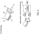
- FIG. 2 is a schematic view of exemplary parts which may be used for sensor 44 in the disclosed pump assembly 10.
- the 3D rotary sensor 44 is a monolithic sensor sensitive to the magnetically flux density applied orthogonally and parallel to its surface, thus providing the capability of sensing magnetic flux density in three (3) directions: x, y, and z, without contact.
- the sensor 44 may sense any magnet moving its in surroundings by measuring and processing the three spatial components of the magnetic flux density vector.
- the signal processing of the ⁇ C / microcontroller (which corresponds to PCB / controller 40) shown in FIG. 2 may be designed to acquire SIN and COS analog information via the 3D rotary sensor 44.
- the controller 40 may be is designed to process any signal corrections for sensitivity mismatch and offset to compensate non-ideal magnetic field angle components, for example, in accordance with an embodiment.
- An angular position calculation (e.g., arctangent interpolation) may be performed and translated to a digital output signal (a kHz PWM signal) for measurement by a demo board and/or processing by an application module or other controller associated with the pump assembly 10.
- this schematic illustration is exemplary only and should be understood to be an non-limiting embodiment for processing using the disclosed 3D rotary sensor 44 and controller 40.
- the controller 26 (and optionally its PCB / board 40) may include other components including, but not limited to, integrated LIN inductors and other sensors (e.g., temperature sensor) mounted thereon.
- the controller 26 may be electrically coupled to a power source (e.g., battery) via a local interconnect network (LIN) bus interface, for example.
- LIN local interconnect network
- positive and negative power connectors may be also overmolded into the controller cover.
- 3D rotary sensor as disclosed herein allows for use of a single controller circuit board for detection relating to the operation of the pump and rotation of a relative shaft (as opposed to using two or more circuit boards that are mounted perpendicularly relative to one another, as described previously, to detect motion of a shaft).
- controller boards may be used in the assembly or associated with the pump for controlling operation thereof.
- the 3D rotary sensor 44 as described above and illustrated in in the embodiments of FIGS. 3-5 is designed detect motion associated with the magnet 50 / drive shaft 32 / motor 28 in the pump assembly 10, it should be noted that, depending on the positioning and alignment of the controller 26, motor 28, and pump 22 in the assembly 10, the ECU may detect or sense features associated with other parts of the assembly, including parts of the pump 22. For example, if the assembly includes a controller flanked by a motor and a pump, such as shown in FIGS. 6-7 , then the 3D rotary sensor of the ECU can be positioned to detect rotation of the pump shaft (which may or may not be the same as drive shaft 32 of the motor 28), or the drive shaft of the motor 28.
- a plane across the first face 42 of the PCB / circuit board 40 and/or 40A is positioned in alignment with axis A and/or A2 of the drive shaft(s) of the motor and/or pump.
- the PCB is placed within housing 18 and/or 18A such that it is parallel to the axis A and/or A2 of the drive shaft of the pump (which may be drive shaft 32, 32A, or another shaft that is driven by that shaft).
Landscapes
- Engineering & Computer Science (AREA)
- Mechanical Engineering (AREA)
- General Engineering & Computer Science (AREA)
- Physics & Mathematics (AREA)
- General Physics & Mathematics (AREA)
- Details And Applications Of Rotary Liquid Pumps (AREA)
- Rotary Pumps (AREA)
- Details Of Reciprocating Pumps (AREA)
- Structures Of Non-Positive Displacement Pumps (AREA)
Description
- This application claims priority to provisional patent application
62/462,078, filed on February 22, 2017 - The present disclosure is generally related to a pump for providing pressurized fluid to a system. More specifically, the pump is associated with powertrain and is provided in an assembly with controller board(s).
- It is known, in some cases, to provide a dedicated electrical motor and a controller (with a circuit board and other electrical components) for operation of a fluid pump.
FIG. 1 shows an example of apump assembly 100 with apump 102,motor 104, andcontroller 106 in axial alignment. For example,US Patent App. No. 2015/0316062 describes a pump assembly that includes an electric motor and different selectable pump covers, and is suitable for mounting within a transmission fluid reservoir for transferring automatic transmission fluid (ATF). The pump assembly includes a stator housing having a cylindrical cavity for receiving ATF contained in the transmission fluid reservoir.US Patent No. 5,197,865 describes a pump assembly that includes a pump head that is coupled to a permanent magnet rotor.WO 2017/025201 relates to devices, for example a gear pump, for pumping fluids and methods of using the aforesaid devices to pump fluids. - Typically, the controller includes a printed circuit board (PCB) that runs in the axial direction (along the y-axis of
FIG. 1 ) of the pump. For example, the PCB 108 may be provided in the housing of thecontroller 106. This PCB can contain the main controller. Typically, thePCB 108 is oriented in the axial direction of the pump assembly so that itsmain face 112 faces in the radial direction. - In addition to the
PCB 108, arotary sensor 114 sometimes is used to detect (indirectly) rotational speed of the motor/pump elements. This detection or sensing is typically done via mounting thesensor 114 on a second circuit board. A typical approach of mounting a second PCB 116 - shown in the form of a 1-D shaft position sensing PCB - is in a perpendicular direction relative to thePCB 108. Because the rotary sensor(s) that are used are typically 1-D or 2-D sensors, they can only detect rotation of objects (e.g., shafts, magnets, etc.) parallel to the sensor's main face. As such, the main (front) face of thesensor 114 needs to face the rotating pump part(s) (including the motor and drive shaft), thus resulting in the fact that thesecond PCB 116 includingsensor 114 must be perpendicular to thePCB 108. - As such, many pumps have the disadvantage of requiring two circuit boards in their design. This requires connection between the two boards, increasing cooling and functioning risk as well as cost.
- The invention provides a pump assembly (10) comprising: a pump (22) having a pump housing (24), the pump (22) having an inlet for receiving input fluid and a pump outlet for outputting pressurized fluid, and a drive shaft (32) for driving parts of the pump (22) to pressurize the input fluid for output from the pump housing;an electric motor (28) configured to drive the drive shaft of the pump;a controller (26) configured to drive the drive shaft (32) of the pump (22), the controller (26) comprising a circuit board having a first side for mounting electrical components thereon, the circuit board being oriented in an axial direction of the pump (22) so that its first side faces in a radial direction;a magnet (50) fixedly attached on a rotatable element of either the pump (22) or the electric motor (28) for rotation therewith;a 3D rotary sensor (44) mounted on the first side of the circuit board, the 3D rotary sensor (44) comprising a front face positioned parallel to the first side of the circuit board such that the front face of the 3D rotary sensor (44) also faces in the radial direction, the 3D rotary sensor (44) configured to detect both (a) motion parallel to its front face and (b) motion in a plane perpendicular to its front face, including rotary motion of the pump (22), for output to the controller (26),wherein the 3D rotary sensor (44) is positioned in proximity to the magnet (50) to detect rotary motion thereof in the plane perpendicular to the front face of the 3D rotary sensor (44) such that an angular position of the rotatable element is determined.
- The invention also provides a method for detecting rotary motion of a pump (22) in such a pump assembly (10), the method comprising:
- driving the drive shaft (32);
- inputting fluid into the inlet of the pump (22);
- pressurizing input fluid using the pump (22);
- detecting, via the 3D rotary sensor (44), rotary motion of the drive shaft of the pump (22);
- controlling, using the controller (26), the pump output based on the detection from the 3D rotary sensor (44); and
- discharging the pressurized fluid through the pump outlet.
- Other aspects, features, and advantages of the present disclosure will become apparent from the following detailed description, the accompanying drawings, and the appended claims.
-
-
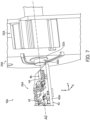
FIG. 1 shows an example of a pump assembly using perpendicularly positioned controller boards according to the prior art. -
FIG. 2 is a schematic drawing of signal processing and features associated with a 3-D rotary sensor, used with a circuit board in the controller portion of disclosed embodiments herein. -
FIG. 3 is a cross-sectional view of a pump assembly, in accordance with one embodiment. -
FIG. 4 is a detailed cross-sectional view of the pump assembly ofFIG. 3 , showing an axially mounted circuit board and 3D sensor in its controller portion/housing, adjacent a motor. -
FIG. 5 is a detailed view of the circuit board and motor of the pump assembly ofFIG. 3 , in accordance with an embodiment, showing a schematic of the relative positioning of the components when using a sensor to sense features of the motor. -
FIG. 6 is a cross-sectional view of a pump assembly, in accordance with another embodiment. -
FIG. 7 is a detailed view of a circuit board and a pump provided in a pump assembly, such as the assembly ofFIG. 6 , showing a schematic of the relative positioning of the components when using a 3D sensor to sense features of a pump and its shaft. - The location, direction, and use of the term "side" herein and throughout this disclosure with reference to the
controller 26, circuit board, 3D sensor, and any of the components of thepump assembly 10 are not intended to be limiting, and it should be understood that such features could also be referred to as a top, bottom, upper, lower, first, second, etc. in this disclosure. The location, direction, and corresponding terms are simply for explanatory purposes with reference to the Figures of the illustrated embodiment. - As noted in greater detail below, numerous embodiments as disclosed herein employ the use of a 3D rotary sensor for detecting rotary motion of a pump (directly or indirectly). Throughout this disclosure, a 3D rotary sensor is defined as a monolithic, integrated circuit (IC) sensor that is configured to detect motion on 3 axes - i.e., x, y, and z axes, as generally represented in
FIG. 2 andFIG. 3 . In the described embodiments, the 3D rotary sensor may be used with a magnet, and, since such a sensor is sensitive to magnetic flux density that is parallel to and perpendicular to the IC sensor mounting face, determinations (e.g., motion or rotation readings) of perpendicularly mounted magnets may be detected. -
FIG. 3 illustrates apump assembly 10, in accordance with an embodiment herein, with its housings and components positioned longitudinally along an axis A (in the Y-direction, or along the Y-axis). The axis A is the axis in which the drive shaft (e.g.,drive shaft 32 of the pump 22) of thepump assembly 10 is configured to rotate and drive the parts (pump, motor, etc.) therein. Thepump assembly 10 may include a number of housings and/or casings that are assembled or fastened together, or may include a single housing that contains the herein disclosed parts and/or housings and casings therein. Thepump assembly 10 includes an assembly inlet 14-1 for inputting fluid, such as a lubricant (e.g., oil or transmission fluid), and an assembly outlet 16-1 for outputting fluid, i.e., fluid that is pressurized by apump 22 contained therein. In an embodiment, the direction of flow into the assembly inlet and from the assembly outlet may be perpendicular to an overall axial length of thepump assembly 10. For example, the inlet 14-1 and/or the outlet 16-1 may either or both be positioned in and along Z-axis. The fluid enters thepump assembly 10 through the assembly inlet and is guided through aninlet passage 14A, shown inFIG. 4 , defined by an inlet pipe to thepump 22. The inlet pipe has an axial length and is fluidly connected to thepump 22 via an inlet thereof. Pressurized fluid from thepump 22 is output via anoutput passage 16A, also shown inFIG. 4 , defined by an outlet pipe and through theassembly outlet 16. The outlet pipe has an axial length and may be parallel to the inlet pipe, for example, in one embodiment. - The inlet pipe and outlet pipe are fluidly connected to the
pump 22. Thepump 22 is encased by a pumphydraulic housing 24, also referred to herein as apump casing 24. In accordance with an embodiment, thepump casing 24 may be integrally formed with the inlet pipe and outlet pipe. Thepump casing 24 encloses the functional pump parts therein and may be shaped to accommodate its pumping parts as well as an outlet passage for directing output flow towards the outlet passage defined in the outlet pipe. - The inlet and outlet pipes associated with the
pump 22 in theassembly 10 may be formed from metal, plastic, or any other suitable material. The length of theinlet pipe 14A and/oroutlet pipe 16A is not intended to be limiting. In an embodiment, lightweight aluminum or plastic may be used for at least part of the length of the pipes. Moreover, the length(s) of the pipe(s) may be adjusted to accommodate other parts associated with the pump, e.g., such as a pressure relief valve, which are not specifically illustrated here. - The type of
pump 22 and its parts provided in thepump assembly 10 is not limited. In accordance with an embodiment, thepump 22 has a gerotor drive, wherein an inner rotor is rotatable driven by thedrive shaft 32 to in turn rotatable drive an outer rotor. The inner rotor is fixedly secured to theshaft 32 for rotation about axis A with thedrive shaft 32. The outer rotor 52 is rotatably received in the pump parts housing. As is understood by one of ordinary skill in the art, rotation of the inner rotor also rotates the outer rotor via their intermeshed teeth to pressurize the input fluid received in areas between the complimentary parts for output from thepump 22, and thus such details are not described here. In another embodiment, thepump 22 is a variable vane pump that includes a number of vanes therein, a rotor, and a control slide that rotates or pivots about a pin within the housing between a first slide position and a second slide position to adjust displacement of the pump through the outlet. The drive shaft may be configured to drive the rotor of the pump, for example. - The
pump 22 is associated with a powertrain and is provided in theassembly 10 with controller board(s). Thepump assembly 10 may supply pressurized fluid to a transmission and/or an engine of an automotive vehicle, for example. The powertrain refers to the components that generate power. An associated powertrain may include simply the engine and transmission, in accordance with an embodiment. In another embodiment, the associated powertrain may include additional parts - e.g., drive shafts, gears, differential - in addition to the engine and transmission. In yet another embodiment, the associated powertrain may include an electric motor and controller. Accordingly, one of ordinary skill in the art should understand additional parts or components that may be included with a powertrain, and thus the above noted examples should not be limiting. - In the
pump assembly 10, at least onecontroller 26 is housed in acontroller housing portion 18 or module of thepump assembly 10. Thepump 22 and anelectric motor 28 are axially aligned with thecontroller 26 on axis A; in one embodiment, as shown inFIGS. 3 and4 , thepump 22 andcontroller 26 are provided on opposing axial sides of themotor 28. More specifically, as shown in the cross-sectional view ofFIG. 3 , for example, thepump 22 and its housing 24 (described below) are provided on one side (e.g., a right side as shown inFIG. 3 ) of themotor 28 and itscasing 30 and thecontroller 26 and itshousing 18 are provided on an opposite axial side (e.g., a left side as shown inFIG. 3 ) of themotor 28 and itscasing 30. In accordance with an embodiment, then, themotor 28 may be flanked by thecontroller 26 and pump 22 (and thus, their housings are arranged in the same manner). The illustrated arrangement ofFIG. 3 is not intended to be limiting, however. In an embodiment, thepump housing 24, themotor casing 30, and thecontroller housing portion 18 are connected together within thepump assembly 10. Inside thepump assembly 10, adrive shaft 32 connects theelectric motor 28 to thepump 22. Thedrive shaft 32 is driven about axis A by theelectric motor 28 to drive the components of thepump 22. Thecontroller 26 controls and thus drives theelectric motor 28 to drive theshaft 32. Further, as described in greater detail below, the controller 26 (in particular, its 3D rotary sensor) may be positioned, in one embodiment, and configured to detect rotation of the motor shaft (which may or may not be the same asdrive shaft 32 of the motor 28). - The illustrated embodiment of
FIGS. 3 and4 generally shows thedrive shaft 32 as being a single shaft that extends from theelectric motor 28 and to thepump 22, such that theshaft 32 that is designed to drive the parts is the same shaft. However, in accordance with an embodiment, theelectric motor 28 may have its own motor drive shaft configured to be driven about an axis, and still connected to thepump 22. Theelectric motor 28 may be configured to drive the (separate) drive shaft of thepump 22 via the motor drive shaft. - The
electric motor 28 includes arotor 34 and a stator 36 (seeFIG. 4 ). Therotor 34 is connected to theshaft 32 is contained within thecasing 30 along with thestator 36. Themotor casing 30 is generally cylindrical and thestator 36 may be fixed thereto. - The
pump 22,motor 28, andcontroller 26, and their respective housings, may be secured together in thepump assembly 10 via connectors, fasteners, bolts, and the like, which is generally known in the art. - The
controller 26 ofassembly 10 is configured to operate or drive the electric motor 28 (e.g., control a magnetic field of thestator 36 of the motor 28), to thus control and drive thepump 22. As shown inFIGS. 3-4 , thecontroller 26 includes an electronic control unit, or ECU. - The ECU includes a circuit board 40 - or PCB (printed circuit board) - mounted within
housing 18, shown here positioned longitudinally (in the Y-direction) along axis A. The PCB may be provided in thehousing portion 18 of the controller. This PCB may contain the main controller, for example. The PCB /circuit board 40 has a first face 42 (or first side) and a second face 43 (or second side), thesecond face 43 being on an opposite side of thefirst face 42. Eachside FIGS. 3 ,4 , and5 show multiple components provided on eitherface pump assembly 10. In the illustrated embodiment, thecircuit board 40 is oriented in an axial (Y) direction of the axis A of thepump assembly 10, so that itsfirst face 42 faces upwardly (as shown inFIG. 5 and6 ) in a radial direction (from or relative to axis A). In an embodiment, a longitudinal portion, surface, or face of the circuit board /PCB 40 is axially aligned with thedrive shaft 32 on the same axis (axis A). As is generally known in the art, a number of components (sensors and the like) may be mounted on thecircuit board 40 for communicating information such that the ECU/controller 26 may control the pump assembly components. Positioning of thecircuit board 40 in the longitudinal direction (along axis A) and in axial alignment with the shaft (shaft 32 and pump drive shaft, and other components) in thehousing 18 as shown inFIGS. 3 and4 results in the components occupying less area in the assembly and allows for improved cooling efficiency of the electrical components contained therein. - In accordance with an embodiment herein, the ECU also includes a
3D rotary sensor 44. When the3D sensor 44 is positioned on thecircuit board 40, it allows the ECU to determine, measure, or sense features in all three axes (as described previously). A face of the3D rotary sensor 44 is positioned such that it is parallel with a face of the PCB /circuit board 40 when thesensor 44 is mounted thereon for sensing and detecting and placed in thepump assembly 10. In the illustrated embodiment, the3D rotary sensor 44 is mounted on thefirst face 42 of thecircuit board 40. That is, in one embodiment, a face of the 3D sensor face is parallel to thetop face 42 of the PCB /circuit board 40. However, in another embodiment, the3D rotary sensor 44 may be mounted in a similar orientation on a bottom thesecond face 43 or side of the PCB /circuit board 40. Accordingly, instead of being limited to sensing in a single axis (x-axis) or the axial direction or along the x-y axis, the positioning of the3D rotary sensor 44 in the pump assembly 10 (such as shown inFIG. 5 orFIG. 7 ) enables reading in the y-z or x-z axis, or combination of both, along with readings using the x-y axis. Accordingly, as described herein, an angular position of the object (e.g., driveshaft 32 or motor shaft) may be measured or sensed even though the 3D rotary sensor 44 (or its body) is positioned on thecircuit board 40. The3D rotary sensor 44 itself has afront face 46 that is positioned parallel to thefirst face 42 of thecircuit board 40 when it is mounted thereon, such that thefront face 46 also faces the radial direction (see, e.g.,FIG. 5 ). In this embodiment, the3D rotary sensor 44 is configured to detect at least motion parallel to itsfront face 46 and motion in a plane perpendicular to itsfront face 46, including rotary motion of the pump, for output to thecontroller 26 during use of thepump assembly 10. Because thesensor 44 is capable of sensing movement in the plane perpendicular to it, it can sense the rotary motion of the motor/ pump elements next to it (y-z) even in this orientation. - In accordance with the illustrated embodiment of the
pump assembly 10, the3D rotary sensor 44 is designed to detect motor shaft rotation, i.e., rotation of thedrive shaft 32. To detect angular position of the shaft, in one embodiment, thedrive shaft 32 has amagnet 50 fixedly attached on or near its end such that themagnet 50 rotates with thedrive shaft 32 about axis A. Thus, the ECU may act as a field oriented controller that detects a magnetic field from themagnet 50. More specifically, the3D rotary sensor 44 is positioned on thecircuit board 40 relative to themagnet 50 so that the magnetic field therefrom is detected, thus resulting in the ability to determine, via the controller components / ECU, the shaft's angular position (and thus its rotational speed). For example, as shown inFIG. 5 , the3D rotary sensor 44 may be provided in the form of a sensor chip that may be mounted near or at an end of thecircuit board 40 on itsface 42 and proximal to themotor 28, so that thesensor 44 is positioned closer to themotor 28,drive shaft 32, andmagnet 50 associated therewith. Providing the3D rotary sensor 44 near or at the end of thecircuit board 40 allows for closer positioning relative to the motor / drive shaft / magnet and thus more accurate reading(s). - Limiting the distance between the
3D rotary sensor 44 and themagnet 50 within the housings/assembly may contribute to greater accuracy with regards to determining the rotary speed of the pump. In an embodiment, thesensor 44 is positioned between approximately 2 mm - approximately 4 mm (both inclusive) away from or relative to themagnet 50. Of course, such distances are only exemplary and not intended to be limiting. - Specifically, it should be noted that the illustrated embodiment is not intended to be limiting. The
sensor 44 may be positioned in any number of places on thecircuit board 40, including on its opposite face (face 43). - The
magnet 50 may be a dipole magnet mounted on theshaft 32 and positioned such that it faces thecontroller housing 18. As such, the 3D rotary sensor is configured to detect rotation of the dipole magnet via its magnetic field, so that it may be used by the controller for determining the rotary motion of the drive shaft (via algorithms / calculations). However, thesensor 44 may sense any type of magnet moving in its surrounding environment and is not intended to be limited to the noted example. Moreover, as further explained below, thesensor 44 may be used to sense a magnet mounted on a shaft or another element associated with thepump 22 itself. - Accordingly, the herein disclosed assembly provides a method for sensing rotary motion of a pump in a pump assembly by using a 3D rotary sensor. Based on the readings from
sensor 44 and calculations determined by the ECU, parts of thepump assembly 10 may be controlled viacontroller 26. In one embodiment, during operation, theelectric motor 28 is driven using thecontroller 26, i.e., thecontroller 26 drives thedrive shaft 32 and themotor 28. In the illustrated embodiment, driving thedrive shaft 32 results in driving thepump 22. Fluid is input through the assembly inlet of the pump assembly and into the inlet of thepump 22. The input fluid is pressurized using thepump 22. As the pump operates, the 3D rotary sensor detects rotary motion of thepump 22 via detecting motion of the magnet / motor / drive shaft. The detections or readings from thesensor 44 are used by the ECU /controller 26 to determine any adjustments for thepump assembly 10. In one embodiment, the speed of theelectric motor 28 is controlled based on the detection by the3D rotary sensor 44. The pressurized fluid from thepump 22 is discharged through the assembly outlet. - In another embodiment, parts of the
pump 22 may be controlled based on the detection and sensing by3D rotary sensor 44; that is, the3D rotary sensor 44 and PCB / controller may be positioned adjacent to and relative to the pump (and its drive shaft), and configured for detection corresponding to the pump.FIG. 6 shows an example of an arrangement of apump assembly 10A that may includecontroller 26A provided in ahousing 18A that is flanked by amotor 28A and apump 22A, each in their respective casing and housings, 30A and 24A. Thepump assembly 10A may have similar components as previously noted above in the embodiments described with reference toFIGS. 2-5 , and thus all of these features are not necessarily repeated here. Still, it should be understood that such features described with reference to pumpassembly 10 inFIGS. 2-5 may be included in theassembly 10A. For example, thepump assembly 10A includes an assembly inlet (not shown) for inputting fluid, such as a lubricant (e.g., oil or transmission fluid), and an assembly outlet (not shown) for outputting fluid, i.e., fluid that is pressurized bypump 22A contained therein. In an embodiment, the direction of flow into the assembly inlet and from the assembly outlet may be perpendicular to an overall axial length of thepump assembly 10. For example, the inlet and/or the outlet may either or both be positioned in and along Z-axis. -
FIG. 7 is a detailed view of acircuit board 40A of an ECU of at least onecontroller 26A mounted relative to pump 22A, such as in thepump assembly 10A ofFIG. 6 , in accordance with another embodiment of this disclosure. Here, the controller 26 (in particular, its 3D rotary sensor) is positioned and is configured to control and/or drive thepump 22A (e.g., via detection rotation of the pump drive shaft, which may or may not be the same as the motor drive shaft). Although the housings for the controller/circuit board and pump are not explicitly shown here, it should be understood that thepump 22A may be contained aseparate housing 24A for housing its components (e.g., pump drive shaft, vanes/rotors/gears, control slide, etc.) therein, such as shown inFIG. 6 . Similarly, thecircuit board 40A may be contained in ahousing 18A (seeFIG. 6 ) or enclosure that is part of, or connected to (e.g., via fasteners or bolts), the housing of thepump 22A. - A
motor 28A may be provided on an opposite side of thepump 22A, such as shown inFIG. 6 , for example, in amotor casing 30A. Accordingly, in one embodiment, thepump assembly 10A may include thepump 22A being flanked on either of its side by thecontroller 26 andmotor 28A. The illustrated arrangement ofFIG. 6 is not intended to be limiting, however. - Like the previously described embodiment, the PCB /
circuit board 40A ofcontroller 26A has a first face 42 (or first side) and a second face 43 (or second side that is opposite to the first face 42) for mounting electrical components thereon, each side having a substantially flat surface. In the illustrated embodiment, thecircuit board 40A is oriented in an axial direction (in the Y-direction) of the axis A2 of thepump assembly 10, so that itsfirst face 42 faces upwardly in a radial direction (from or relative to axis A2). Both faces and flat surfaces of the PCB may be positioned to extend in the longitudinal / Y-direction of thepump assembly 10A. Again, positioning thecircuit board 40 in the longitudinal direction (axis A, or Y-direction or Y-axis) and in axial alignment with theshaft 32A of thepump 22A as schematically represented inFIG. 7 results in the components occupying less area and allows for improved cooling efficiency of the electrical components. In an embodiment, a longitudinal portion, surface, or face of the circuit board /PCB 40A is axially aligned with thedrive shaft 32A on the same axis (axis A). The3D rotary sensor 44 may be mounted on the first face 42 (or second face 43) of thecircuit board 40A. Afront face 46 of thesensor 44 is positioned parallel to the relative face of thecircuit board 40A when it is mounted thereon, such that thefront face 46 also faces the radial direction. - As previously discussed, in accordance with an embodiment, the orientation of the
circuit board 40A may be relative to adrive shaft 32A of the pump itself 22A, so that the pump shaft rotation/speed of thedrive shaft 32A of thepump 22A may be determined via the3D sensor 44 and the controller. The3D rotary sensor 44 may detect pump shaft rotation using amagnet 50A (e.g., a dipole magnet) that is fixedly attached on or near the end of thedrive shaft 32A such that themagnet 50A rotates with thedrive shaft 32A about axis A2. Thus, the ECU may act as a field oriented controller that detects a magnetic field from themagnet 50A. Accordingly, the3D rotary sensor 44 enables reading in the y-z or x-z axis, or combination of both, along with readings using the x-y axis. In this embodiment, the3D rotary sensor 44 is configured to detect at least motion parallel to itsfront face 46 and motion in a plane perpendicular to itsfront face 46, including rotary motion of the pump, for output to thecontroller 26 during use of the pump. - Because the
sensor 44 is capable of sensing movement in the plane perpendicular to it, it can sense the rotary motion of the pump elements next to it (y-z) in this orientation. Accordingly, an angular position of the object (e.g., driveshaft 32A) may be measured or sensed even though the 3D rotary sensor 44 (or its body) is positioned on thecircuit board 40. In the illustrated embodiment, the controller or ECU may be configured to sensedrive shaft 32A features (rotation, speed) and control the operation or rotation of thedrive shaft 32A of thepump 22A. However, the 3D rotary sensor need not be limited to positioning adjacent thedrive shaft 32A. For example, in another embodiment, the ECU / controller andsensor 44 associated withpump 22A may be used to sense a position of a control slide withinpump 22A and/or change (e.g., reduce) a position of the control slide, resulting in a change in output of pressurized fluid. Thus, it should be understood that the readings fromsensor 44 may be used by controller /ECU to control any number of parts of thepump 22A. - Accordingly, the herein disclosed assembly provides a method for sensing rotary motion of a pump on more than one axis by using a 3D rotary sensor and a controller (ECU). The controller is an ECU that includes a printed circuit board (PCB) that runs in the axial direction (along the y-axis) of the pump and/or pump assembly. Fluid is input through the inlet of the
pump 22A. The input fluid is pressurized using thepump 22A. As the pump operates, the 3D rotary sensor detects rotary motion of thepump 22A via detecting motion of themagnet 50A / drive shaft. Based on the readings fromsensor 44 and calculations determined by the ECU, parts of thepump 22A may be controlled via controller. In one embodiment, during operation, thedrive shaft 32A of thepump 22A is driven using the controller. In another embodiment, the controller may alter a position of the slide within the pump housing such that displacement through the pump outlet is altered. The pressurized fluid from thepump 22A is discharged through its outlet. - The type of
pump 22A inFIGS. 6 and7 and its parts provided in thepump assembly 10 is not limited. In accordance with an embodiment, thepump 22A has a gerotor drive with an inner rotor and an outer rotor. The inner rotor is fixedly secured to theshaft 32 for rotation about axis A with thedrive shaft 32. In another embodiment, thepump 22A is a variable vane pump that includes a number of vanes therein, a rotor, and a control slide that rotates or pivots about a pin within the housing between a first slide position and a second slide position to adjust displacement of the pump through the outlet. Thedrive shaft 32A may be configured to drive the rotor of the pump, for example. - Also, it is again noted that limiting the distance between the
3D rotary sensor 44 and themagnet 50A may contribute to greater accuracy with regards to determining the rotary speed of the pump. In an embodiment, thesensor 44 is positioned between approximately 2 mm - approximately 4 mm (both inclusive) away from or relative to themagnet 50A. Of course, such distances are only exemplary and not intended to be limiting. - The herein disclosed combination of
circuit board 40 and3D rotary sensor 44 in the illustrated embodiments eliminates previous multi-board connection risks and provide smaller overall packaging with regards to the controller portion. The3D rotary sensor 44 also provides greater freedom of choice for its orientation on the PCB / circuit board 40 (as opposed to itsface 46 being directly mounted in front of a shaft). It also allows for increased design flexibility with regards to the parts of the pump assembly and mounting relative to the shaft/magnet being detected. The 3D rotary sensor provides an increased advantage of detecting motion relative to a third axis. In particular, although detection in the axial direction (e.g., y-axis) is relatively or generally zero, the 3D rotary sensor allows for detection in the X and Z axes for determining rotary movement of the pump. - Additionally, using the 3D rotary sensor maintains / allows for optimal cooling of the circuit board and controller parts. It allows for the
circuit board 40 to maintain its orientation such that it is positioned axially within the housing, with the 3D sensor thereon, so that thermal heat sinking is maximized. Mounting the 3D sensor on a side of the circuit board still allows detection of motion in the three axes. Further, mounting of the 3D sensor on a side of the circuit board reduces, if not provides limited to no risk of damage to the chip/sensor itself, including its exposure to heat (as compared to traditional mountings that require perpendicular mountings directly in front of and adjacent to the detected object). - The electrical components can be developed independent of pump construction. Moreover, costs are lowered since additional sensor(s), an additional circuit board, wiring, and assembly (time) which are typically provided in conventional systems, are either reduced or eliminated in the herein disclosed
pump assembly 10. - The type and manufacturer of the
3D rotary sensor 44 are not intended to be limiting.FIG. 2 is a schematic view of exemplary parts which may be used forsensor 44 in the disclosedpump assembly 10. In an embodiment, the3D rotary sensor 44 is a monolithic sensor sensitive to the magnetically flux density applied orthogonally and parallel to its surface, thus providing the capability of sensing magnetic flux density in three (3) directions: x, y, and z, without contact. Thesensor 44 may sense any magnet moving its in surroundings by measuring and processing the three spatial components of the magnetic flux density vector. - In an embodiment, the signal processing of the µC / microcontroller (which corresponds to PCB / controller 40) shown in
FIG. 2 may be designed to acquire SIN and COS analog information via the3D rotary sensor 44. Thecontroller 40 may be is designed to process any signal corrections for sensitivity mismatch and offset to compensate non-ideal magnetic field angle components, for example, in accordance with an embodiment. An angular position calculation (e.g., arctangent interpolation) may be performed and translated to a digital output signal (a kHz PWM signal) for measurement by a demo board and/or processing by an application module or other controller associated with thepump assembly 10. Of course, this schematic illustration is exemplary only and should be understood to be an non-limiting embodiment for processing using the disclosed3D rotary sensor 44 andcontroller 40. - The controller 26 (and optionally its PCB / board 40) may include other components including, but not limited to, integrated LIN inductors and other sensors (e.g., temperature sensor) mounted thereon. The
controller 26 may be electrically coupled to a power source (e.g., battery) via a local interconnect network (LIN) bus interface, for example. In addition, conventionally, positive and negative power connectors may be also overmolded into the controller cover. - Use of the 3D rotary sensor as disclosed herein allows for use of a single controller circuit board for detection relating to the operation of the pump and rotation of a relative shaft (as opposed to using two or more circuit boards that are mounted perpendicularly relative to one another, as described previously, to detect motion of a shaft). However, it should be understood that other controller boards may be used in the assembly or associated with the pump for controlling operation thereof.
- In addition, although the
3D rotary sensor 44 as described above and illustrated in in the embodiments ofFIGS. 3-5 is designed detect motion associated with themagnet 50 /drive shaft 32 /motor 28 in thepump assembly 10, it should be noted that, depending on the positioning and alignment of thecontroller 26,motor 28, and pump 22 in theassembly 10, the ECU may detect or sense features associated with other parts of the assembly, including parts of thepump 22. For example, if the assembly includes a controller flanked by a motor and a pump, such as shown inFIGS. 6-7 , then the 3D rotary sensor of the ECU can be positioned to detect rotation of the pump shaft (which may or may not be the same asdrive shaft 32 of the motor 28), or the drive shaft of themotor 28. - In some embodiments, a plane across the
first face 42 of the PCB /circuit board 40 and/or 40A is positioned in alignment with axis A and/or A2 of the drive shaft(s) of the motor and/or pump. In an embodiment, the PCB is placed withinhousing 18 and/or 18A such that it is parallel to the axis A and/or A2 of the drive shaft of the pump (which may be driveshaft - While the principles of the disclosure have been made clear in the illustrative embodiments set forth above, it will be apparent to those skilled in the art that various modifications may be made to the structure, arrangement, proportion, elements, materials, and components used in the practice of the disclosure.
- It will thus be seen that the features of this disclosure have been fully and effectively accomplished. It will be realized, however, that the foregoing preferred specific embodiments have been shown and described for the purpose of illustrating the functional and structural principles of this disclosure and are subject to change. Therefore, this disclosure includes all modifications encompassed within the spirit scope of the following claims.
Claims (16)
- A pump assembly (10) comprising:a pump (22) having a pump housing (24), the pump (22) having an inlet for receiving input fluid and a pump outlet for outputting pressurized fluid, and a drive shaft (32) for driving parts of the pump (22) to pressurize the input fluid for output from the pump housing;an electric motor (28) configured to drive the drive shaft of the pump;a controller (26) configured to drive the drive shaft (32) of the pump (22), the controller (26) comprising a circuit board having a first side for mounting electrical components thereon, the circuit board being oriented in an axial direction of the pump (22) so that its first side faces in a radial direction;a magnet (50) fixedly attached on a rotatable element of either the pump (22) or the electric motor (28) for rotation therewith;a 3D rotary sensor (44) mounted on the first side of the circuit board, the 3D rotary sensor (44) comprising a front face positioned parallel to the first side of the circuit board such that the front face of the 3D rotary sensor (44) also faces in the radial direction, the 3D rotary sensor (44) configured to detect both (a) motion parallel to its front face and (b) motion in a plane perpendicular to its front face, including rotary motion of the pump (22), for output to the controller (26),wherein the 3D rotary sensor (44) is positioned in proximity to the magnet (50) to detect rotary motion thereof in the plane perpendicular to the front face of the 3D rotary sensor (44) such that an angular position of the rotatable element is determined.
- The pump assembly (10) according to claim 1, further comprising a motor drive shaft for the electric motor (28), the electric motor (28) being connected to the pump (22), the motor drive shaft being configured to be driven about an axis, and wherein the electric motor (28) is configured to drive the drive shaft of the pump (22) via the motor drive shaft.
- The pump assembly (10) according to claim 2, wherein the motor drive shaft of the electric motor (28) and the drive shaft (32) of the pump (22) are the same in that a single shaft extends from the electric motor to the pump (22) for rotation about the axis, and wherein the axis for the single shaft is parallel with the circuit board.
- The pump assembly (10) according to claim 1, wherein the 3D rotary sensor is configured to detect rotary motion of the drive shaft (32) of the pump (22), and wherein the controller is configured to adjust a speed at which the drive shaft of the pump (22) is driven based on the detection.
- The pump assembly (10) according to claim 1, wherein the magnet is a dipole magnet, wherein the drive shaft (32) of the pump (22) has the dipole magnet mounted thereon, and wherein the 3D rotary sensor is configured to detect rotation of the dipole magnet such that the controller determines rotary motion of the drive shaft of the pump (22) based on the detected rotation.
- The pump assembly (10) according to claim 1, further comprising:an assembly inlet for inputting fluid, wherein the pump (22) receives input fluid from the assembly inlet;an assembly outlet for outputting fluid;the electric motor being contained within a motor casing;a motor drive shaft connecting the electric motor to the pump (22), the motor drive shaft being configured to be driven about an axis by the electric motor for driving parts of the pump (22) to pressurize the input fluid for output from the pump housing;the controller being configured to drive the electric motor (38), wherein the pump (22) and the electric motor (38) are axially aligned with the controller
andan outlet passage communicating the pump outlet with the assembly outlet to discharge the pressurized fluid. - The pump assembly (10) according to claim 2 or claim 6, wherein the magnet is a dipole magnet, wherein the motor drive shaft has the dipole magnet mounted thereon, wherein the 3D rotary sensor is mounted near or at an end of the circuit board and proximal to the electric motor so that the 3D rotary sensor is positioned closer to the electric motor, drive shaft, and dipole magnet associated therewith, and wherein the 3D rotary sensor (44) is configured to detect rotation of the dipole magnet such that the controller determines rotary motion of the motor drive shaft based on the detected rotation, and wherein the controller is configured to adjust speed for driving the motor drive shaft based on the detection.
- The pump assembly (10) according to claim 1 or claim 6, wherein the electric motor (28) is flanked by the controller and the pump (22) in the pump assembly (10).
- The pump assembly (10) according to claim 1 or claim 6, wherein the pump (22) is flanked by the controller (26) and the electric motor (28) in the pump assembly (10).
- A method for detecting rotary motion of a pump (22) in the pump assembly (10) of claim 1 or claim 6, the method comprising:driving the drive shaft (32);inputting fluid into the inlet of the pump (22);pressurizing input fluid using the pump (22);detecting, via the 3D rotary sensor (44), rotary motion of the drive shaft of the pump (22);controlling, using the controller (26), the pump output based on the detection from the 3D rotary sensor (44); anddischarging the pressurized fluid through the pump outlet.
- The method according to claim 10, wherein the magnet is a dipole magnet, wherein the pump assembly (10) further comprises the dipole magnet mounted on the drive shaft of the pump (22), and wherein the detecting via 3D rotary sensor (44) comprises detecting rotation of the dipole magnet such that the controller determines rotary motion of the drive shaft based on the detected rotation.
- The method according to claim 10, the method further comprising:driving the electric motor (28) using the controller (26), anddriving the motor drive shaft;wherein the detecting via 3D rotary sensor (44) comprises detect rotation of the motor drive shaft such that the controller determines rotary motion of the pump (22) based on the detected rotation.
- The method according to claim 12, wherein the motor drive shaft of the electric motor (28) and the drive shaft (32) of the pump (22) are the same in that a single shaft extends from the electric motor to the pump for rotation about the axis, and wherein the axis for the single shaft is parallel with the circuit board.
- The method according to claim 10, wherein the controlling of the pump output comprises adjusting a speed at which the drive shaft (32) of the pump (22) is driven based on the detecting via the 3D rotary sensor (44).
- The method according to claim 12, wherein the magnet (50) is a dipole magnet, wherein the motor drive shaft of the electric motor (28) has the dipole magnet mounted thereon, wherein the 3D rotary sensor (44) is mounted near or at an end of the circuit board and proximal to the electric motor (28) so that the 3D rotary sensor (44) is positioned closer to the electric motor (28), drive shaft, and dipole magnet associated therewith, and wherein the 3D rotary sensor (44) is configured to detect rotation of the dipole magnet such that the controller (26) determines rotary motion of the motor drive shaft of the electric motor (28) based on the detected rotation.
- The method according to claim 12, wherein the controlling of the pump output comprises adjusting a speed at which the motor drive shaft of the electric motor (28) is driven based on the detecting via the 3D rotary sensor (44).
Applications Claiming Priority (2)
| Application Number | Priority Date | Filing Date | Title |
|---|---|---|---|
| US201762462078P | 2017-02-22 | 2017-02-22 | |
| PCT/IB2018/051078 WO2018154464A1 (en) | 2017-02-22 | 2018-02-21 | Pump assembly having a controller including a circuit board and 3d rotary sensor for detecting rotation of its pump |
Publications (3)
| Publication Number | Publication Date |
|---|---|
| EP3586149A1 EP3586149A1 (en) | 2020-01-01 |
| EP3586149A4 EP3586149A4 (en) | 2020-11-18 |
| EP3586149B1 true EP3586149B1 (en) | 2023-07-26 |
Family
ID=63167669
Family Applications (1)
| Application Number | Title | Priority Date | Filing Date |
|---|---|---|---|
| EP18758395.0A Active EP3586149B1 (en) | 2017-02-22 | 2018-02-21 | Pump assembly having a controller including a circuit board and 3d rotary sensor for detecting rotation of its pump |
Country Status (8)
| Country | Link |
|---|---|
| US (2) | US20180238924A1 (en) |
| EP (1) | EP3586149B1 (en) |
| JP (1) | JP6898457B2 (en) |
| KR (2) | KR102354656B1 (en) |
| CN (1) | CN110476069B (en) |
| CA (1) | CA3053733C (en) |
| MX (1) | MX2019009959A (en) |
| WO (1) | WO2018154464A1 (en) |
Families Citing this family (6)
| Publication number | Priority date | Publication date | Assignee | Title |
|---|---|---|---|---|
| DE102017122804A1 (en) * | 2017-09-29 | 2019-04-04 | Fresenius Medical Care Deutschland Gmbh | Medical pump drive, pump and blood treatment device |
| CN111237209B (en) * | 2020-02-17 | 2021-08-03 | 苏州欣皓信息技术有限公司 | Water pump rotating wheel stability monitoring method and device, electronic equipment and storage medium |
| JP7585010B2 (en) * | 2020-12-01 | 2024-11-18 | 株式会社前川製作所 | Refrigeration System |
| US11680565B2 (en) * | 2021-02-08 | 2023-06-20 | Schaeffler Technologies AG & Co. KG | Motor-pump system |
| US12486841B2 (en) * | 2022-07-08 | 2025-12-02 | Blue-White Industries, Ltd. | Pivotable pump head |
| CN115479005A (en) * | 2022-09-03 | 2022-12-16 | 深圳市梯子数据有限公司 | Portable device for switching working modes |
Family Cites Families (27)
| Publication number | Priority date | Publication date | Assignee | Title |
|---|---|---|---|---|
| US5197865A (en) * | 1990-10-16 | 1993-03-30 | Micropump Corporation | Integral electronically commutated drive system |
| JPH05248363A (en) * | 1992-03-03 | 1993-09-24 | Kayaba Ind Co Ltd | Rotary pump drive |
| JP3619687B2 (en) * | 1998-11-18 | 2005-02-09 | アルプス電気株式会社 | Rotation type sensor |
| JP2000291557A (en) | 1999-04-07 | 2000-10-17 | Sanden Corp | Electric compressor |
| US6607360B2 (en) * | 2001-07-17 | 2003-08-19 | Itt Industries Flojet | Constant pressure pump controller system |
| US7188021B2 (en) * | 2004-10-25 | 2007-03-06 | Litens Automotive Partnership | Angular position sensor-based engine controller system |
| US7269992B2 (en) * | 2005-06-15 | 2007-09-18 | Honeywell International Inc. | Magnet orientation and calibration for small package turbocharger speed sensor |
| JP4992395B2 (en) * | 2006-11-27 | 2012-08-08 | 株式会社豊田自動織機 | Electric compressor |
| US10677617B2 (en) * | 2007-05-30 | 2020-06-09 | Infineon Technologies Ag | Shaft-integrated angle sensing device |
| JP5531186B2 (en) * | 2008-12-18 | 2014-06-25 | サンデン株式会社 | Drive circuit integrated electric compressor |
| CN102097912B (en) | 2009-12-11 | 2015-01-28 | 德昌电机(深圳)有限公司 | Permanent magnet motor |
| CN102593997B (en) | 2011-01-07 | 2016-08-03 | 德昌电机(深圳)有限公司 | Motor |
| CN102200540B (en) * | 2011-02-17 | 2013-09-11 | 爱德利科技股份有限公司 | Detection module for rotating spindle |
| DE102012200092A1 (en) * | 2012-01-04 | 2013-07-04 | Robert Bosch Gmbh | Sensor device for non-contact detection of a rotational property of a rotatable object |
| US9007054B2 (en) * | 2012-04-04 | 2015-04-14 | Allegro Microsystems, Llc | Angle sensor with misalignment detection and correction |
| GB2505226A (en) | 2012-08-23 | 2014-02-26 | Melexis Technologies Nv | Arrangement, method and sensor for measuring an absolute angular position using a multi-pole magnet |
| CN202886044U (en) * | 2012-09-29 | 2013-04-17 | 黄山华讯电子科技有限公司 | Integrated wireless detector for load, torque and rotational speed of rod pumped well with screw pump |
| US10590935B2 (en) * | 2012-10-29 | 2020-03-17 | Pierburg Pump Technology Gmbh | Automotive electric liquid pump |
| JP6049650B2 (en) * | 2014-03-11 | 2016-12-21 | 旭化成エレクトロニクス株式会社 | Non-contact rotation angle sensor |
| US9297346B2 (en) * | 2014-03-17 | 2016-03-29 | Ford Global Technologies, Llc | Camshaft position determination |
| US10087927B2 (en) * | 2014-05-01 | 2018-10-02 | Ghsp, Inc. | Electric motor with flux collector |
| US10087932B2 (en) | 2014-11-19 | 2018-10-02 | American Axle & Manufacturing, Inc. | G-rotor pump assembly |
| JP6472678B2 (en) | 2015-02-19 | 2019-02-20 | 日立オートモティブシステムズ株式会社 | Electric oil pump |
| JP6596884B2 (en) | 2015-03-31 | 2019-10-30 | 日本電産株式会社 | motor |
| JP6590535B2 (en) * | 2015-05-29 | 2019-10-16 | 日本電産トーソク株式会社 | Pump device |
| GB2541031B (en) * | 2015-08-07 | 2017-09-06 | Magpumps Ltd | Gear pump for pumping fluid |
| DE202015105244U1 (en) * | 2015-10-05 | 2017-01-09 | Ebm-Papst St. Georgen Gmbh & Co. Kg | Pump-motor unit |
-
2018
- 2018-02-21 MX MX2019009959A patent/MX2019009959A/en unknown
- 2018-02-21 JP JP2019543884A patent/JP6898457B2/en active Active
- 2018-02-21 WO PCT/IB2018/051078 patent/WO2018154464A1/en not_active Ceased
- 2018-02-21 CN CN201880019614.0A patent/CN110476069B/en active Active
- 2018-02-21 US US15/901,416 patent/US20180238924A1/en not_active Abandoned
- 2018-02-21 CA CA3053733A patent/CA3053733C/en active Active
- 2018-02-21 KR KR1020197027633A patent/KR102354656B1/en active Active
- 2018-02-21 KR KR1020227001758A patent/KR102460051B1/en active Active
- 2018-02-21 EP EP18758395.0A patent/EP3586149B1/en active Active
- 2018-02-21 US US16/485,650 patent/US11796555B2/en active Active
Also Published As
| Publication number | Publication date |
|---|---|
| WO2018154464A1 (en) | 2018-08-30 |
| KR20190121343A (en) | 2019-10-25 |
| JP6898457B2 (en) | 2021-07-07 |
| EP3586149A4 (en) | 2020-11-18 |
| US20220299021A1 (en) | 2022-09-22 |
| JP2020508411A (en) | 2020-03-19 |
| US11796555B2 (en) | 2023-10-24 |
| EP3586149A1 (en) | 2020-01-01 |
| CA3053733C (en) | 2023-01-10 |
| KR102460051B1 (en) | 2022-10-27 |
| MX2019009959A (en) | 2019-11-05 |
| CA3053733A1 (en) | 2018-08-30 |
| KR20220013007A (en) | 2022-02-04 |
| KR102354656B1 (en) | 2022-01-24 |
| US20180238924A1 (en) | 2018-08-23 |
| CN110476069B (en) | 2022-04-29 |
| CN110476069A (en) | 2019-11-19 |
Similar Documents
| Publication | Publication Date | Title |
|---|---|---|
| CA3053733C (en) | Pump assembly having a controller including a circuit board and 3d rotary sensor for detecting rotation of its pump | |
| US7095198B1 (en) | Speed sensor for a power sensor module | |
| EP2264406B1 (en) | Motor-driven throttle valve device with inductive throttle sensor | |
| JP4531379B2 (en) | Sensor for variable displacement pump | |
| JP6793124B2 (en) | Clutch actuator | |
| US20160061637A1 (en) | Integrated angle sensing device | |
| JP2003289648A (en) | Electronic control actuator | |
| CN102570722B (en) | There is the EPS motor of steering angle sensor | |
| WO2007132062A1 (en) | Oval gear meter | |
| US20250277488A1 (en) | Thermistor flow path | |
| EP3448742B1 (en) | Angular rotation sensor system | |
| CN114543846A (en) | Encoder units, drives and robots | |
| CN107078669B (en) | Automatic filling control technology | |
| US7469575B2 (en) | Sensing rotation of an engine component relative to an engine body using a starter ring | |
| JP6432463B2 (en) | Valve unit | |
| CN111284560B (en) | Steering position rotation sensor fitting | |
| CN223230990U (en) | Integrated motor cover structure | |
| CN222457775U (en) | Compressor and rotation position detection mechanism thereof, thermal management system and vehicle | |
| JP7561797B2 (en) | Magnetic field detection device, magnetic sensor module, electric control device, motor and transmission | |
| US20240218873A1 (en) | Split output port for pump with internal temperature measurement device | |
| KR102264315B1 (en) | Multi-turn Absolute Torque Angle Sensor Module | |
| JP6561808B2 (en) | Electronic equipment | |
| CN120418543A (en) | Positive displacement machine with speed sensor |
Legal Events
| Date | Code | Title | Description |
|---|---|---|---|
| STAA | Information on the status of an ep patent application or granted ep patent |
Free format text: STATUS: THE INTERNATIONAL PUBLICATION HAS BEEN MADE |
|
| PUAI | Public reference made under article 153(3) epc to a published international application that has entered the european phase |
Free format text: ORIGINAL CODE: 0009012 |
|
| STAA | Information on the status of an ep patent application or granted ep patent |
Free format text: STATUS: REQUEST FOR EXAMINATION WAS MADE |
|
| 17P | Request for examination filed |
Effective date: 20190905 |
|
| AK | Designated contracting states |
Kind code of ref document: A1 Designated state(s): AL AT BE BG CH CY CZ DE DK EE ES FI FR GB GR HR HU IE IS IT LI LT LU LV MC MK MT NL NO PL PT RO RS SE SI SK SM TR |
|
| AX | Request for extension of the european patent |
Extension state: BA ME |
|
| DAV | Request for validation of the european patent (deleted) | ||
| DAX | Request for extension of the european patent (deleted) | ||
| A4 | Supplementary search report drawn up and despatched |
Effective date: 20201015 |
|
| RIC1 | Information provided on ipc code assigned before grant |
Ipc: F04B 49/20 20060101ALI20201009BHEP Ipc: H02K 7/14 20060101ALI20201009BHEP Ipc: H02K 11/21 20160101ALI20201009BHEP Ipc: F04D 15/00 20060101ALI20201009BHEP Ipc: F04C 14/08 20060101ALI20201009BHEP Ipc: G01P 3/00 20060101ALI20201009BHEP Ipc: G01P 13/00 20060101AFI20201009BHEP Ipc: G01P 3/487 20060101ALI20201009BHEP |
|
| RIN1 | Information on inventor provided before grant (corrected) |
Inventor name: WANG, LIPING |
|
| GRAP | Despatch of communication of intention to grant a patent |
Free format text: ORIGINAL CODE: EPIDOSNIGR1 |
|
| STAA | Information on the status of an ep patent application or granted ep patent |
Free format text: STATUS: GRANT OF PATENT IS INTENDED |
|
| INTG | Intention to grant announced |
Effective date: 20230213 |
|
| GRAS | Grant fee paid |
Free format text: ORIGINAL CODE: EPIDOSNIGR3 |
|
| GRAA | (expected) grant |
Free format text: ORIGINAL CODE: 0009210 |
|
| STAA | Information on the status of an ep patent application or granted ep patent |
Free format text: STATUS: THE PATENT HAS BEEN GRANTED |
|
| AK | Designated contracting states |
Kind code of ref document: B1 Designated state(s): AL AT BE BG CH CY CZ DE DK EE ES FI FR GB GR HR HU IE IS IT LI LT LU LV MC MK MT NL NO PL PT RO RS SE SI SK SM TR |
|
| REG | Reference to a national code |
Ref country code: CH Ref legal event code: EP |
|
| P01 | Opt-out of the competence of the unified patent court (upc) registered |
Effective date: 20230628 |
|
| REG | Reference to a national code |
Ref country code: IE Ref legal event code: FG4D |
|
| REG | Reference to a national code |
Ref country code: DE Ref legal event code: R096 Ref document number: 602018054078 Country of ref document: DE |
|
| REG | Reference to a national code |
Ref country code: GB Ref legal event code: 746 Effective date: 20231012 |
|
| REG | Reference to a national code |
Ref country code: LT Ref legal event code: MG9D |
|
| REG | Reference to a national code |
Ref country code: NL Ref legal event code: MP Effective date: 20230726 |
|
| REG | Reference to a national code |
Ref country code: AT Ref legal event code: MK05 Ref document number: 1592511 Country of ref document: AT Kind code of ref document: T Effective date: 20230726 |
|
| PG25 | Lapsed in a contracting state [announced via postgrant information from national office to epo] |
Ref country code: NL Free format text: LAPSE BECAUSE OF FAILURE TO SUBMIT A TRANSLATION OF THE DESCRIPTION OR TO PAY THE FEE WITHIN THE PRESCRIBED TIME-LIMIT Effective date: 20230726 |
|
| PG25 | Lapsed in a contracting state [announced via postgrant information from national office to epo] |
Ref country code: GR Free format text: LAPSE BECAUSE OF FAILURE TO SUBMIT A TRANSLATION OF THE DESCRIPTION OR TO PAY THE FEE WITHIN THE PRESCRIBED TIME-LIMIT Effective date: 20231027 |
|
| PG25 | Lapsed in a contracting state [announced via postgrant information from national office to epo] |
Ref country code: IS Free format text: LAPSE BECAUSE OF FAILURE TO SUBMIT A TRANSLATION OF THE DESCRIPTION OR TO PAY THE FEE WITHIN THE PRESCRIBED TIME-LIMIT Effective date: 20231126 |
|
| PG25 | Lapsed in a contracting state [announced via postgrant information from national office to epo] |
Ref country code: SE Free format text: LAPSE BECAUSE OF FAILURE TO SUBMIT A TRANSLATION OF THE DESCRIPTION OR TO PAY THE FEE WITHIN THE PRESCRIBED TIME-LIMIT Effective date: 20230726 Ref country code: RS Free format text: LAPSE BECAUSE OF FAILURE TO SUBMIT A TRANSLATION OF THE DESCRIPTION OR TO PAY THE FEE WITHIN THE PRESCRIBED TIME-LIMIT Effective date: 20230726 Ref country code: PT Free format text: LAPSE BECAUSE OF FAILURE TO SUBMIT A TRANSLATION OF THE DESCRIPTION OR TO PAY THE FEE WITHIN THE PRESCRIBED TIME-LIMIT Effective date: 20231127 Ref country code: NO Free format text: LAPSE BECAUSE OF FAILURE TO SUBMIT A TRANSLATION OF THE DESCRIPTION OR TO PAY THE FEE WITHIN THE PRESCRIBED TIME-LIMIT Effective date: 20231026 Ref country code: LV Free format text: LAPSE BECAUSE OF FAILURE TO SUBMIT A TRANSLATION OF THE DESCRIPTION OR TO PAY THE FEE WITHIN THE PRESCRIBED TIME-LIMIT Effective date: 20230726 Ref country code: LT Free format text: LAPSE BECAUSE OF FAILURE TO SUBMIT A TRANSLATION OF THE DESCRIPTION OR TO PAY THE FEE WITHIN THE PRESCRIBED TIME-LIMIT Effective date: 20230726 Ref country code: IS Free format text: LAPSE BECAUSE OF FAILURE TO SUBMIT A TRANSLATION OF THE DESCRIPTION OR TO PAY THE FEE WITHIN THE PRESCRIBED TIME-LIMIT Effective date: 20231126 Ref country code: HR Free format text: LAPSE BECAUSE OF FAILURE TO SUBMIT A TRANSLATION OF THE DESCRIPTION OR TO PAY THE FEE WITHIN THE PRESCRIBED TIME-LIMIT Effective date: 20230726 Ref country code: GR Free format text: LAPSE BECAUSE OF FAILURE TO SUBMIT A TRANSLATION OF THE DESCRIPTION OR TO PAY THE FEE WITHIN THE PRESCRIBED TIME-LIMIT Effective date: 20231027 Ref country code: FI Free format text: LAPSE BECAUSE OF FAILURE TO SUBMIT A TRANSLATION OF THE DESCRIPTION OR TO PAY THE FEE WITHIN THE PRESCRIBED TIME-LIMIT Effective date: 20230726 Ref country code: AT Free format text: LAPSE BECAUSE OF FAILURE TO SUBMIT A TRANSLATION OF THE DESCRIPTION OR TO PAY THE FEE WITHIN THE PRESCRIBED TIME-LIMIT Effective date: 20230726 |
|
| PG25 | Lapsed in a contracting state [announced via postgrant information from national office to epo] |
Ref country code: PL Free format text: LAPSE BECAUSE OF FAILURE TO SUBMIT A TRANSLATION OF THE DESCRIPTION OR TO PAY THE FEE WITHIN THE PRESCRIBED TIME-LIMIT Effective date: 20230726 |
|
| PG25 | Lapsed in a contracting state [announced via postgrant information from national office to epo] |
Ref country code: ES Free format text: LAPSE BECAUSE OF FAILURE TO SUBMIT A TRANSLATION OF THE DESCRIPTION OR TO PAY THE FEE WITHIN THE PRESCRIBED TIME-LIMIT Effective date: 20230726 |
|
| REG | Reference to a national code |
Ref country code: DE Ref legal event code: R097 Ref document number: 602018054078 Country of ref document: DE |
|
| PG25 | Lapsed in a contracting state [announced via postgrant information from national office to epo] |
Ref country code: SM Free format text: LAPSE BECAUSE OF FAILURE TO SUBMIT A TRANSLATION OF THE DESCRIPTION OR TO PAY THE FEE WITHIN THE PRESCRIBED TIME-LIMIT Effective date: 20230726 Ref country code: RO Free format text: LAPSE BECAUSE OF FAILURE TO SUBMIT A TRANSLATION OF THE DESCRIPTION OR TO PAY THE FEE WITHIN THE PRESCRIBED TIME-LIMIT Effective date: 20230726 Ref country code: ES Free format text: LAPSE BECAUSE OF FAILURE TO SUBMIT A TRANSLATION OF THE DESCRIPTION OR TO PAY THE FEE WITHIN THE PRESCRIBED TIME-LIMIT Effective date: 20230726 Ref country code: EE Free format text: LAPSE BECAUSE OF FAILURE TO SUBMIT A TRANSLATION OF THE DESCRIPTION OR TO PAY THE FEE WITHIN THE PRESCRIBED TIME-LIMIT Effective date: 20230726 Ref country code: DK Free format text: LAPSE BECAUSE OF FAILURE TO SUBMIT A TRANSLATION OF THE DESCRIPTION OR TO PAY THE FEE WITHIN THE PRESCRIBED TIME-LIMIT Effective date: 20230726 Ref country code: CZ Free format text: LAPSE BECAUSE OF FAILURE TO SUBMIT A TRANSLATION OF THE DESCRIPTION OR TO PAY THE FEE WITHIN THE PRESCRIBED TIME-LIMIT Effective date: 20230726 Ref country code: SK Free format text: LAPSE BECAUSE OF FAILURE TO SUBMIT A TRANSLATION OF THE DESCRIPTION OR TO PAY THE FEE WITHIN THE PRESCRIBED TIME-LIMIT Effective date: 20230726 |
|
| PLBE | No opposition filed within time limit |
Free format text: ORIGINAL CODE: 0009261 |
|
| STAA | Information on the status of an ep patent application or granted ep patent |
Free format text: STATUS: NO OPPOSITION FILED WITHIN TIME LIMIT |
|
| 26N | No opposition filed |
Effective date: 20240429 |
|
| PG25 | Lapsed in a contracting state [announced via postgrant information from national office to epo] |
Ref country code: SI Free format text: LAPSE BECAUSE OF FAILURE TO SUBMIT A TRANSLATION OF THE DESCRIPTION OR TO PAY THE FEE WITHIN THE PRESCRIBED TIME-LIMIT Effective date: 20230726 |
|
| PG25 | Lapsed in a contracting state [announced via postgrant information from national office to epo] |
Ref country code: MC Free format text: LAPSE BECAUSE OF FAILURE TO SUBMIT A TRANSLATION OF THE DESCRIPTION OR TO PAY THE FEE WITHIN THE PRESCRIBED TIME-LIMIT Effective date: 20230726 |
|
| REG | Reference to a national code |
Ref country code: CH Ref legal event code: PL |
|
| PG25 | Lapsed in a contracting state [announced via postgrant information from national office to epo] |
Ref country code: LU Free format text: LAPSE BECAUSE OF NON-PAYMENT OF DUE FEES Effective date: 20240221 |
|
| PG25 | Lapsed in a contracting state [announced via postgrant information from national office to epo] |
Ref country code: CH Free format text: LAPSE BECAUSE OF NON-PAYMENT OF DUE FEES Effective date: 20240229 |
|
| PG25 | Lapsed in a contracting state [announced via postgrant information from national office to epo] |
Ref country code: LU Free format text: LAPSE BECAUSE OF NON-PAYMENT OF DUE FEES Effective date: 20240221 Ref country code: CH Free format text: LAPSE BECAUSE OF NON-PAYMENT OF DUE FEES Effective date: 20240229 |
|
| PG25 | Lapsed in a contracting state [announced via postgrant information from national office to epo] |
Ref country code: BG Free format text: LAPSE BECAUSE OF FAILURE TO SUBMIT A TRANSLATION OF THE DESCRIPTION OR TO PAY THE FEE WITHIN THE PRESCRIBED TIME-LIMIT Effective date: 20230726 |
|
| PG25 | Lapsed in a contracting state [announced via postgrant information from national office to epo] |
Ref country code: BG Free format text: LAPSE BECAUSE OF FAILURE TO SUBMIT A TRANSLATION OF THE DESCRIPTION OR TO PAY THE FEE WITHIN THE PRESCRIBED TIME-LIMIT Effective date: 20230726 |
|
| REG | Reference to a national code |
Ref country code: BE Ref legal event code: MM Effective date: 20240229 |
|
| PG25 | Lapsed in a contracting state [announced via postgrant information from national office to epo] |
Ref country code: BE Free format text: LAPSE BECAUSE OF NON-PAYMENT OF DUE FEES Effective date: 20240229 |
|
| PG25 | Lapsed in a contracting state [announced via postgrant information from national office to epo] |
Ref country code: IE Free format text: LAPSE BECAUSE OF NON-PAYMENT OF DUE FEES Effective date: 20240221 |
|
| PG25 | Lapsed in a contracting state [announced via postgrant information from national office to epo] |
Ref country code: IE Free format text: LAPSE BECAUSE OF NON-PAYMENT OF DUE FEES Effective date: 20240221 Ref country code: BE Free format text: LAPSE BECAUSE OF NON-PAYMENT OF DUE FEES Effective date: 20240229 |
|
| PG25 | Lapsed in a contracting state [announced via postgrant information from national office to epo] |
Ref country code: CY Free format text: LAPSE BECAUSE OF FAILURE TO SUBMIT A TRANSLATION OF THE DESCRIPTION OR TO PAY THE FEE WITHIN THE PRESCRIBED TIME-LIMIT; INVALID AB INITIO Effective date: 20180221 |
|
| PG25 | Lapsed in a contracting state [announced via postgrant information from national office to epo] |
Ref country code: HU Free format text: LAPSE BECAUSE OF FAILURE TO SUBMIT A TRANSLATION OF THE DESCRIPTION OR TO PAY THE FEE WITHIN THE PRESCRIBED TIME-LIMIT; INVALID AB INITIO Effective date: 20180221 |
|
| PG25 | Lapsed in a contracting state [announced via postgrant information from national office to epo] |
Ref country code: TR Free format text: LAPSE BECAUSE OF FAILURE TO SUBMIT A TRANSLATION OF THE DESCRIPTION OR TO PAY THE FEE WITHIN THE PRESCRIBED TIME-LIMIT Effective date: 20230726 |
|
| PGFP | Annual fee paid to national office [announced via postgrant information from national office to epo] |
Ref country code: GB Payment date: 20260223 Year of fee payment: 9 |
|
| PGFP | Annual fee paid to national office [announced via postgrant information from national office to epo] |
Ref country code: DE Payment date: 20260220 Year of fee payment: 9 |
|
| PGFP | Annual fee paid to national office [announced via postgrant information from national office to epo] |
Ref country code: IT Payment date: 20260220 Year of fee payment: 9 |
|
| PGFP | Annual fee paid to national office [announced via postgrant information from national office to epo] |
Ref country code: FR Payment date: 20260224 Year of fee payment: 9 |