EP3585675B1 - A control assembly for power steering - Google Patents
A control assembly for power steering Download PDFInfo
- Publication number
- EP3585675B1 EP3585675B1 EP18710233.0A EP18710233A EP3585675B1 EP 3585675 B1 EP3585675 B1 EP 3585675B1 EP 18710233 A EP18710233 A EP 18710233A EP 3585675 B1 EP3585675 B1 EP 3585675B1
- Authority
- EP
- European Patent Office
- Prior art keywords
- control sleeve
- shaft
- sleeve
- pin
- chamber
- Prior art date
- Legal status (The legal status is an assumption and is not a legal conclusion. Google has not performed a legal analysis and makes no representation as to the accuracy of the status listed.)
- Active
Links
Images



Classifications
-
- B—PERFORMING OPERATIONS; TRANSPORTING
- B62—LAND VEHICLES FOR TRAVELLING OTHERWISE THAN ON RAILS
- B62D—MOTOR VEHICLES; TRAILERS
- B62D5/00—Power-assisted or power-driven steering
- B62D5/06—Power-assisted or power-driven steering fluid, i.e. using a pressurised fluid for most or all the force required for steering a vehicle
- B62D5/08—Power-assisted or power-driven steering fluid, i.e. using a pressurised fluid for most or all the force required for steering a vehicle characterised by type of steering valve used
- B62D5/083—Rotary valves
-
- B—PERFORMING OPERATIONS; TRANSPORTING
- B62—LAND VEHICLES FOR TRAVELLING OTHERWISE THAN ON RAILS
- B62D—MOTOR VEHICLES; TRAILERS
- B62D5/00—Power-assisted or power-driven steering
- B62D5/06—Power-assisted or power-driven steering fluid, i.e. using a pressurised fluid for most or all the force required for steering a vehicle
- B62D5/065—Power-assisted or power-driven steering fluid, i.e. using a pressurised fluid for most or all the force required for steering a vehicle characterised by specially adapted means for varying pressurised fluid supply based on need, e.g. on-demand, variable assist
-
- B—PERFORMING OPERATIONS; TRANSPORTING
- B62—LAND VEHICLES FOR TRAVELLING OTHERWISE THAN ON RAILS
- B62D—MOTOR VEHICLES; TRAILERS
- B62D6/00—Arrangements for automatically controlling steering depending on driving conditions sensed and responded to, e.g. control circuits
- B62D6/08—Arrangements for automatically controlling steering depending on driving conditions sensed and responded to, e.g. control circuits responsive only to driver input torque
Definitions
- the present disclosure is generally related to a control assembly for power steering.
- Power steering or assist steering systems are implemented for reducing the amount of human effort required to turn the steering wheel of an automobile.
- these systems utilize hydraulic lines to add supplementary steering force to a steering gear by way of hydraulic fluid via a hydraulic pressure cylinder.
- This supplementary steering force is typically turned off and on by a control assembly that includes a shaft disposed within and rotatable relative to a valve sleeve.
- the shaft extends between a torsion bar and a steering gear and conveys rotational movement between the steering wheel and a steering gear. In operation the shaft must be slightly rotated before the control assembly allows the supplementary steering force to be applied.
- the torsion bar applies a rotational resistance on the shaft which typically requires a certain amount of human input on the steering wheel to move the steering wheel from its current position in order to rotate the shaft and turn on the supplementary steering force.
- the supplementary steering force multiplies the human effort making it easier to turn the steering wheel.
- these systems measure the amount of torque applied by the human effort and provide correlational force. While these systems provide a significant improvement over steering configurations without power or assist systems, they still ultimately require a certain amount of human input for overcoming the initial rotational resistance of the torsion bar required to activate the supplemental force.
- the subject invention provides a control assembly for power steering in an automobile which comprises a valve assembly that includes a valve sleeve defining a cavity and a shaft that extends through the cavity.
- the shaft is rotatable on an axis of rotation relative to the valve sleeve in a first rotational direction and a second rotational direction.
- the shaft When installed in an automobile, the shaft extends from a torsion bar and for conveying rotational movement between a steering column and a steering gear.
- the valve assembly includes a first hydraulic circuit interchangeable from an unassisted condition to an assisted condition. In the unassisted condition, the torsion bar applies a rotational resistance that prevents rotation of the shaft and corresponding turning of a driving wheel.
- the shaft must be slightly rotated to switch to the assisted condition wherein the first hydraulic circuit hydraulically actuates steering of the automobile. More particularly, the shaft must be rotated in either the first or second rotational directions a circumferential actuating distance.
- the hydraulic actuation assists in steering the automobile via a hydraulic pressure cylinder in a direction dependent upon the rotation of the shaft.
- first hydraulic circuit applies the force required to convey rotational movement between the steering column and a steering gear once the shaft is slightly rotated.
- the control assembly further includes an actuator having a second hydraulic circuit that is interchangeable from an unengaged condition to an engaged condition to apply a circumferential hydraulic force on the shaft that overcomes the rotational resistance of the torsion bar to rotate the shaft in either the first or the second rotational direction the circumferential actuating distance.
- the first hydraulic circuit actuates the hydraulic pressure cylinder thereby supplying the supplemental steering force of the assisted condition thus modulating and possibly eliminating the requirement of human input.
- the second hydraulic circuit does not apply hydraulic force on the shaft and thus the control assembly is free to operate in a traditional manner.
- Example embodiments will now be described more fully with reference to the accompanying drawings.
- the subject embodiments are directed to a control assembly for power steering.
- the example embodiments are only provided so that this disclosure will be thorough, and will fully convey the scope to those who are skilled in the art. Numerous specific details are set forth such as examples of specific components, devices, and methods, to provide a thorough understanding of embodiments of the present disclosure. It will be apparent to those skilled in the art that specific details need not be employed, that example embodiments may be embodied in many different forms and that neither should be construed to limit the scope of the disclosure. In some example embodiments, well-known processes, well-known device structures, and well-known technologies are not described in detail.
- a control assembly 20 in accordance with the subject disclosure is intended for overcoming a rotational resistance associated with conventional power steering systems, namely the rotational resistance required to activate supplementary steering force.
- This supplementary steering force often times only available when a steering wheel is in a non-rotated position.
- the control assembly 20 provides a valve assembly 22 that includes a valve sleeve 24 defining a cavity 52 and a shaft 26 disposed on an axis of rotation A.
- the shaft 26 is disposed in and extends axially through the cavity 52 and is rotatable relative to the valve sleeve 24 from a non-rotated position in a first rotational direction 30 and a second rotational direction 32, i.e., clockwise and counterclockwise.
- the shaft 26 When installed in an automobile, the shaft 26 extends from a torsion bar 62 and conveys rotational movement between a steering column and a steering gear.
- the torsion bar 62 applies a rotational resistance on the shaft 26 preventing rotation until application of torque force which has traditionally required human input via turning of a steering wheel.
- the valve assembly 22 includes first hydraulic circuit 76 interchangeable from an unassisted condition 36 to an assisted condition 34.
- the shaft 26 In the unassisted condition 36, the shaft 26 is subject to the rotational resistance from the torsion bar 62 which prevents rotation of the shaft 26. This rotational resistance is traditionally overcome by a driver turning a steering wheel.
- the first hydraulic circuit 76 changes to the assisted condition 34, wherein the first hydraulic circuit 76 hydraulically actuates steering of the automobile via a hydraulic pressure cylinder 64.
- the shaft 26 is rotated in either the first or second rotational directions 30, 32 a circumferential actuating distance D from the non-rotated position or current position of the steering wheel.
- the non-rotated position of the shaft 26 can be associated with a non-rotated position of a steering wheel.
- the assisted condition 34 provides supplementary steering force which eases or eliminates the effort required to convey rotational movement from the steering wheel and steering column to a steering gear in order to steer the automobile.
- the valve assembly 22 includes an actuator 38 that overcomes the rotational resistance of the torsion bar 62.
- the actuator 38 includes a second hydraulic circuit 86 that is interchangeable from an unengaged condition 42 to an engaged condition 40 that overcomes the rotational resistance of the torsion bar 62 in the unassisted condition 36 by applying circumferential hydraulic force on the shaft 26.
- the circumferential hydraulic force rotates the shaft 26 in either the first or second rotational directions 30, 32 (i.e., clockwise or counterclockwise) the circumferential actuating distance D thereby initiating the assisted condition 34.
- the second hydraulic circuit 86 does not affect the shaft 26.
- the valve sleeve 24 includes a wall 44 extending in a parallel relationship to the axis of rotation A between a first end 46 and a second end 48.
- the wall 44 of the valve sleeve 24 includes an interior surface 50 outlining the cavity 52 and defining a plurality of slots 54 circumferentially spaced apart by ribs 56.
- the slots 54 each extend in a parallel relationship to the axis of rotation A and expand radially outwardly from the interior surface 50.
- Each of these slots 54 includes a slot center axis B and the slots 54 extend symmetrically from the slot center axis B.
- the shaft 26 extends along the axis of rotation A between an input end 58 and an output end 60.
- the shaft 26 is disposed through the cavity 52 with the input end 58 extending axially outwardly from the first end 46 of the valve sleeve 24 and the output end 60 extending axially outwardly from the second end 48 of the valve sleeve 24.
- the torsion bar 62 is in communication with a drive column and extends from the input end 58 of the shaft 26 communicating rotational input from the drive column.
- the shaft 26 defines an exterior shaft surface 66 having a circular cross-section defining a plurality of notches 68 circumferentially spaced apart by guides 70 adjacent to the output end 60.
- the notches 68 each extend about the axis of rotation A and expand radially inwardly.
- the guides 70 include guide side walls 72 that extend radially outwardly from the notches 68 to a guide top surface 74.
- Each of the guide top surfaces 74 include a top surface central axis C and each of the guide top surfaces 74 extend symmetrically from the top surface central axis C.
- each of the top surface central axes C of the shaft 26 are disposed in circumferential alignment with a respective one of the slot central axis B in the unassisted condition 36.
- each of the top surface central axes B are circumferentially spaced from respective one of the slot central axis C in the first rotational direction 30 or the second rotational direction 32 the circumferential actuating distance D in the assisted condition 34 as a result of being urged by the actuator 38.
- the first hydraulic circuit 76 includes a plurality of input assist channels 78 each extending through the wall 44 and one of the ribs 56 of the valve sleeve 24.
- the first hydraulic circuit 76 further includes a plurality of output assist channels 80 with each one of the output assist channels 80 extending through the wall 44 from one of the slots 54 of the valve sleeve 24.
- hydraulic fluid flows freely through all of the output assist channels 80 and thus the hydraulic pressure cylinder 64 is unaffected.
- only select output assist channels 80 may convey the hydraulic pressure.
- Figure 3B illustrates rotation of the shaft 26 in one extreme circumferential distance, however as this circumferential distance changes, the ratio of hydraulic pressure conveyed between individual output assist channels 80 is metered.
- the select output assist channels 80 thus convey fluid to the hydraulic pressure cylinder 64 in the assisted condition 34 in a direction dependent on which select output assist channels 80 convey the hydraulic fluid.
- the control assembly 20 includes at least one hydraulic fluid source 82 providing fluid to the first hydraulic circuit 76.
- the control assembly 20 further includes at least one pressure module 84 pressurizing the first hydraulic circuit 76.
- the second hydraulic circuit 86 of the actuator 38 includes a first actuator channel 88, a second actuator channel 90, and a hydraulic chamber 92.
- a pin 94 divides the hydraulic chamber 92 into a first sub-chamber 96 in fluid communication with the first actuator channel 88 and a second sub-chamber 98 in fluid communication with the second actuator channel 90.
- the pin 94 is urged into the other of the first and second sub-chambers 96, 98. Movement of the pin 94, overcoming the rotational resistance of the torsion bar 62 moves the shaft 26 relative to the valve sleeve 24 the circumferential actuating distance D thus placing the first hydraulic circuit 76 of the valve assembly 22 in the assisted condition 34.
- the second hydraulic circuit 86 is also in fluid communication with the at least one hydraulic fluid source 82 which provides fluid to at least the second hydraulic circuit 86.
- a three-way valve 100 is in selectable fluid communication between the at least one hydraulic fluid source 82 and the first actuator channel 88 and the second actuator channel 90.
- the at least one pressure module 84 pressurizes the second hydraulic circuit 86 and directs fluid towards the three-way valve 100 from the at least one hydraulic fluid source 82.
- An electric control unit 102 is in electric communication with the at least one pressure module 84 and the three-way valve 100 for selectively moving the actuator 38 between the engaged condition 40 and the unengaged condition 42.
- the wall 44 of the valve sleeve 24 includes an exterior surface 104 having a circular cross-section that defines a plurality of grooves 105 expanding radially inwardly.
- Each of the input assist channels 78 and each of the output assist channels 80 extend though the exterior surface 104 of the wall 44 of the valve sleeve 24 from one of the grooves 105.
- a plurality of ring seals 106 are impermeably disposed over and extend at least partially into the grooves 105.
- the first hydraulic circuit 76 and the second hydraulic circuit 86 of the control assembly 20 are in fluid communication with each other and the at least one pressure module 84 includes only a singular pressure module 84 that pressurizes both of the first hydraulic circuit 76 and the second hydraulic circuit 86.
- the first hydraulic circuit 76 and the second hydraulic circuit 86 of the control assembly 20' are not in fluid communication with each other and the at least one pressure module 84 includes two pressure modules 84 with one pressure module 84 pressurizing the first hydraulic circuit 76 and the other pressure module 84 pressurizing the second hydraulic circuit 86.
- the at least one pressure module 84 can include an electric pump.
- the actuator 38 of valve assembly 22 includes a control sleeve 108 having an annular shape attached to the shaft 26 for conjoint rotation with the shaft 26.
- the control sleeve 108 includes an at least one control sleeve aperture 132 extending radially inwardly therethrough.
- the shaft 26 includes at least one shaft aperture 134 extending radially inwardly corresponding to the control sleeve apertures 132.
- a plurality of fasteners 110 extend through the at least one control sleeve aperture 132 and into at least one shaft aperture 134 for attachment between the shaft 26 and the control sleeve 108.
- control sleeve 108 could be incorporated in several existing shafts by way of providing shaft apertures 134.
- the pin 94 extends axially from the control sleeve 108 and the first end 46 of the valve sleeve 24 defines the hydraulic chamber 92.
- the pin 94 extends axially from the control sleeve 108 and into the hydraulic chamber 92 and movement of the pin 94 between sub-chambers 96, 98 moves the control sleeve 108 and shaft 26 relative to the valve assembly 22.
- the first actuator channel 88 and the second actuator channel 90 are at least partially disposed within the valve sleeve 24 from one of the grooves 105 and extend into respective sub-chambers 96, 98.
- the actuator 38' of valve assembly 22' includes a control sleeve 108' having an annular shape attached to the shaft 26 for conjoint rotation with the shaft 26.
- a plurality of fasteners 110 extend through the control sleeve 108' into the shaft 26 for attachment between the shaft 26 and the control sleeve 108' as in the previous embodiment.
- the control sleeve 108' defines at least one control sleeve groove 112 extending circumferentially about the control sleeve 108'.
- a ring seal 106 is disposed over and at least partially in the at least one control sleeve groove 112 for sealing the groove 112.
- the pin 94 extends axially from the valve sleeve 24 and the control sleeve 108 defines the hydraulic chamber 92.
- the first actuator channel 88 is at least partially disposed in the valve sleeve 24 and the second actuator channel 90 is at least partially disposed within the control sleeve 108 from the control sleeve groove 112 for providing fluid to respective sub-chambers 96, 98.
- the actuator 38" of valve assembly 22" is now assembled such that the pin 94 is disposed on the shaft 26 and extends radially outwardly.
- the interior wall 44 of the valve sleeve 24 defines the hydraulic chamber 92.
- a housing 28 surrounds the valve sleeve 24 over the hydraulic chamber 92 for providing hydraulic fluid therein. Accordingly, the pin 94 is aligned with the hydraulic chamber 92 and extends radially outwardly into the hydraulic chamber 92.
- the first actuator channel 88 and the second actuator channel 90 are both at least partially disposed within the valve sleeve 24 from one of the grooves 105 and a housing 28 for providing fluid to respective sub-chambers 96, 98.
- the actuator 38''' of the valve assembly 22''' includes the input side of the shaft 26 defining a plurality of helical teeth 116 extending helically about the axis of rotation A.
- a control sleeve 108''' having an annular shape includes an interior control sleeve surface 118 that defines a plurality of driving teeth 120 engaged with the helical teeth 116.
- the control sleeve 108''' further includes an outer control sleeve surface 122 defining a control sleeve guide 140 extending circumferentially around the control sleeve 108"'.
- the pin 94 defines a pin guide 136 that corresponds with the control sleeve guide 140 and extends circumferentially around the pin 94.
- the pin 94 is disposed in a spaced relationship from the control sleeve 108 and extends in a parallel relationship to the axis of rotation A.
- the housing 28 surrounds the control sleeve 108 and defines the hydraulic chamber 92 that defines a passage 144 which extends radially inwardly between the hydraulic chamber 92 and the control sleeve 108 thus exposing the control sleeve 108 to the pin 94 disposed in the hydraulic chamber 92.
- a spring ring 128 defines an annular shape disposed within the control sleeve guide 140 that extends through the passage 144 into the pin guide 136 for connecting the pin 94 and the control sleeve 108 for conjoint axial movement. During axial movement, the control sleeve 108 is free to rotate with respect to the pin 94.
- the pin 94 includes pin seals 146 disposed on either side of the pin guide 136 for preventing hydraulic fluid from exiting the passage 144 form the hydraulic chamber 92.
- the control sleeve 108 moves axially along the axis of rotation A in a first axial direction 124 and a second axial direction 126 in response to pressure accumulating in the first and second hydraulic sub-chambers 96, 98.
- the axial movement of the shaft 26 rotationally drives the driving teeth 120 which results in corresponding rotation of the shaft 26.
- the resulting rotation of the shaft 26 is in the first rotational direction 30 and the second rotational direction 32 relative to the first axial direction 124 and the second axial direction 126, respectively.
- a hydraulic chamber plug 130 allows installation of the pin 94 and impermeably seals the hydraulic chamber 92.
- the valve sleeve 24 defines a dowel 138 and the control sleeve 108 defines a dowel hole 142 which engages with one another resulting in conjoint rotational movement between the valve sleeve 24 and the control sleeve 108.
- axial movement of the pin 94 rotates the control sleeve 108 and the valve sleeve 24 between the engaged position 40 and the unengaged position 42.
- the first actuator channel 88 and the second actuator channel 90 are at least partially disposed within the housing 28 for providing fluid to respective sub-chambers 96, 98.
Landscapes
- Engineering & Computer Science (AREA)
- Chemical & Material Sciences (AREA)
- Combustion & Propulsion (AREA)
- Transportation (AREA)
- Mechanical Engineering (AREA)
- Power Steering Mechanism (AREA)
Description
- This PCT Patent Application claims the benefit of and priority to
U.S. Provisional Patent Application Serial No. 62/462,403 filed February 23, 2017 - The present disclosure is generally related to a control assembly for power steering.
- This section provides background information related to the present disclosure which is not necessarily prior art.
- Power steering or assist steering systems are implemented for reducing the amount of human effort required to turn the steering wheel of an automobile. Traditionally, these systems utilize hydraulic lines to add supplementary steering force to a steering gear by way of hydraulic fluid via a hydraulic pressure cylinder. This supplementary steering force is typically turned off and on by a control assembly that includes a shaft disposed within and rotatable relative to a valve sleeve. In these systems, the shaft extends between a torsion bar and a steering gear and conveys rotational movement between the steering wheel and a steering gear. In operation the shaft must be slightly rotated before the control assembly allows the supplementary steering force to be applied. The torsion bar applies a rotational resistance on the shaft which typically requires a certain amount of human input on the steering wheel to move the steering wheel from its current position in order to rotate the shaft and turn on the supplementary steering force. To this extent, once the rotational resistance is overcome by the human input and the shaft is slightly rotated, the supplementary steering force multiplies the human effort making it easier to turn the steering wheel. Generally, these systems measure the amount of torque applied by the human effort and provide correlational force. While these systems provide a significant improvement over steering configurations without power or assist systems, they still ultimately require a certain amount of human input for overcoming the initial rotational resistance of the torsion bar required to activate the supplemental force. This amount of required human input can vary drastically as a result of both the speed at which the automobile travels and the weight carried by the automobile. It is therefore desirable to add additional assistance to reduce or completely eliminate the human input required for overcoming sometimes inconsistent rotational resistances in order to initiate the supplementary steering force. Moreover, in applications where steering is autonomous and human effort is unneeded or unwanted, applications which bypass the human element are particularly advantageous. It is thus necessary to further advance the art which has traditionally required a certain amount of human input before application of supplementary steering force. A valve assembly for a power steering system has been disclosed in
US 2014/271309 A1 according to the preamble of claim 1. - The subject invention provides a control assembly for power steering in an automobile which comprises a valve assembly that includes a valve sleeve defining a cavity and a shaft that extends through the cavity. The shaft is rotatable on an axis of rotation relative to the valve sleeve in a first rotational direction and a second rotational direction. When installed in an automobile, the shaft extends from a torsion bar and for conveying rotational movement between a steering column and a steering gear. The valve assembly includes a first hydraulic circuit interchangeable from an unassisted condition to an assisted condition. In the unassisted condition, the torsion bar applies a rotational resistance that prevents rotation of the shaft and corresponding turning of a driving wheel. The shaft must be slightly rotated to switch to the assisted condition wherein the first hydraulic circuit hydraulically actuates steering of the automobile. More particularly, the shaft must be rotated in either the first or second rotational directions a circumferential actuating distance. The hydraulic actuation assists in steering the automobile via a hydraulic pressure cylinder in a direction dependent upon the rotation of the shaft. In other words, first hydraulic circuit applies the force required to convey rotational movement between the steering column and a steering gear once the shaft is slightly rotated. The control assembly further includes an actuator having a second hydraulic circuit that is interchangeable from an unengaged condition to an engaged condition to apply a circumferential hydraulic force on the shaft that overcomes the rotational resistance of the torsion bar to rotate the shaft in either the first or the second rotational direction the circumferential actuating distance. As a result of the rotational movement of the shaft, the first hydraulic circuit actuates the hydraulic pressure cylinder thereby supplying the supplemental steering force of the assisted condition thus modulating and possibly eliminating the requirement of human input. In the unengaged condition, the second hydraulic circuit does not apply hydraulic force on the shaft and thus the control assembly is free to operate in a traditional manner.
- The drawings described herein are for illustrative purposes only of selected embodiments and are not intended to limit the scope of the present invention. The inventive concepts associated with the present disclosure will be more readily understood by reference to the following description in combination with the accompanying drawings wherein:
-
Figure 1 is a perspective view of a valve assembly in accordance with a first embodiment of the invention. -
Figure 2 is an exploded view of the valve assembly illustrating a valve sleeve and a shaft. -
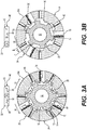
Figure 3A is a sectional view taken along line "AA" ofFigure 1 illustrating the valve assembly in an unassisted condition and an actuator in an unengaged condition. -
Figure 3B is a sectional view taken along line "AA" ofFigure 1 illustrating the valve assembly in an assisted condition and the actuator in an engaged condition. -
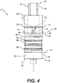
Figure 4 is a side view of a valve assembly in accordance with a second embodiment of the subject disclosure. -
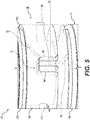
Figure 5 is a close up of an actuator of the valve sleeve presented inFigure 4 . -
Figure 6 is a perspective view of a valve assembly in accordance with a third embodiment of the subject disclosure. -
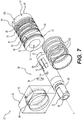
Figure 7 is an exploded view of the valve sleeve presented inFigure 6 illustrating the components of the valve assembly. -
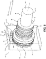
Figure 8 is a perspective view a valve sleeve in accordance with a fourth embodiment of the subject disclosure. -
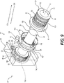
Figure 9 is an exploded view of the valve assembly presented inFigure 8 illustrating a shaft and a control sleeve each having helical teeth. -
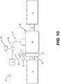
Figure 10 is a schematic view of a control assembly with a first hydraulic circuit and a second hydraulic circuit in fluid communication in accordance with one arrangement of the subject disclosure. -
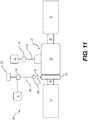
Figure 11 is a schematic view of the control assembly with a separated first hydraulic circuit and second hydraulic circuit in accordance with another arrangement of the subject disclosure. - Example embodiments will now be described more fully with reference to the accompanying drawings. In general, the subject embodiments are directed to a control assembly for power steering. However, the example embodiments are only provided so that this disclosure will be thorough, and will fully convey the scope to those who are skilled in the art. Numerous specific details are set forth such as examples of specific components, devices, and methods, to provide a thorough understanding of embodiments of the present disclosure. It will be apparent to those skilled in the art that specific details need not be employed, that example embodiments may be embodied in many different forms and that neither should be construed to limit the scope of the disclosure. In some example embodiments, well-known processes, well-known device structures, and well-known technologies are not described in detail.
- Referring to the Figures, wherein like numerals indicate corresponding parts throughout the several views, a
control assembly 20 in accordance with the subject disclosure is intended for overcoming a rotational resistance associated with conventional power steering systems, namely the rotational resistance required to activate supplementary steering force. This supplementary steering force often times only available when a steering wheel is in a non-rotated position. - Generally referring to
Figures 1-11 , thecontrol assembly 20 provides avalve assembly 22 that includes avalve sleeve 24 defining acavity 52 and ashaft 26 disposed on an axis of rotation A. Theshaft 26 is disposed in and extends axially through thecavity 52 and is rotatable relative to thevalve sleeve 24 from a non-rotated position in a firstrotational direction 30 and a secondrotational direction 32, i.e., clockwise and counterclockwise. When installed in an automobile, theshaft 26 extends from atorsion bar 62 and conveys rotational movement between a steering column and a steering gear. Thetorsion bar 62 applies a rotational resistance on theshaft 26 preventing rotation until application of torque force which has traditionally required human input via turning of a steering wheel. - The
valve assembly 22 includes firsthydraulic circuit 76 interchangeable from anunassisted condition 36 to an assistedcondition 34. In theunassisted condition 36, theshaft 26 is subject to the rotational resistance from thetorsion bar 62 which prevents rotation of theshaft 26. This rotational resistance is traditionally overcome by a driver turning a steering wheel. Once the rotational resistance of theshaft 26 is overcome, the firsthydraulic circuit 76 changes to the assistedcondition 34, wherein the firsthydraulic circuit 76 hydraulically actuates steering of the automobile via ahydraulic pressure cylinder 64. To overcome the rotational resistance of thetorsion bar 62, theshaft 26 is rotated in either the first or secondrotational directions 30, 32 a circumferential actuating distance D from the non-rotated position or current position of the steering wheel. The non-rotated position of theshaft 26 can be associated with a non-rotated position of a steering wheel. Thus, once theshaft 26 is rotated, the assistedcondition 34 provides supplementary steering force which eases or eliminates the effort required to convey rotational movement from the steering wheel and steering column to a steering gear in order to steer the automobile. To modulate or possibly eliminate the human input requirement to overcome the rotational resistance, thevalve assembly 22 includes anactuator 38 that overcomes the rotational resistance of thetorsion bar 62. To accomplish overcoming the rotational resistance, theactuator 38 includes a secondhydraulic circuit 86 that is interchangeable from anunengaged condition 42 to an engagedcondition 40 that overcomes the rotational resistance of thetorsion bar 62 in theunassisted condition 36 by applying circumferential hydraulic force on theshaft 26. The circumferential hydraulic force rotates theshaft 26 in either the first or secondrotational directions 30, 32 (i.e., clockwise or counterclockwise) the circumferential actuating distance D thereby initiating the assistedcondition 34. In theunengaged condition 42, the secondhydraulic circuit 86 does not affect theshaft 26. - As best illustrated in
Figures 3A and 3B , thevalve sleeve 24 includes awall 44 extending in a parallel relationship to the axis of rotation A between afirst end 46 and asecond end 48. Thewall 44 of thevalve sleeve 24 includes aninterior surface 50 outlining thecavity 52 and defining a plurality ofslots 54 circumferentially spaced apart byribs 56. Theslots 54 each extend in a parallel relationship to the axis of rotation A and expand radially outwardly from theinterior surface 50. Each of theseslots 54 includes a slot center axis B and theslots 54 extend symmetrically from the slot center axis B. - The
shaft 26 extends along the axis of rotation A between aninput end 58 and anoutput end 60. Theshaft 26 is disposed through thecavity 52 with theinput end 58 extending axially outwardly from thefirst end 46 of thevalve sleeve 24 and theoutput end 60 extending axially outwardly from thesecond end 48 of thevalve sleeve 24. Thetorsion bar 62 is in communication with a drive column and extends from theinput end 58 of theshaft 26 communicating rotational input from the drive column. As best illustrated inFigures 3A and 3B , theshaft 26 defines anexterior shaft surface 66 having a circular cross-section defining a plurality ofnotches 68 circumferentially spaced apart byguides 70 adjacent to theoutput end 60. Thenotches 68 each extend about the axis of rotation A and expand radially inwardly. Theguides 70 includeguide side walls 72 that extend radially outwardly from thenotches 68 to a guidetop surface 74. Each of the guide top surfaces 74 include a top surface central axis C and each of the guide top surfaces 74 extend symmetrically from the top surface central axis C. - As illustrated in
Figures 3A , each of the top surface central axes C of theshaft 26 are disposed in circumferential alignment with a respective one of the slot central axis B in theunassisted condition 36. As illustrated inFigure 3B , each of the top surface central axes B are circumferentially spaced from respective one of the slot central axis C in the firstrotational direction 30 or the secondrotational direction 32 the circumferential actuating distance D in the assistedcondition 34 as a result of being urged by theactuator 38. - Still referring to
Figures 3A and 3B , the firsthydraulic circuit 76 includes a plurality of input assistchannels 78 each extending through thewall 44 and one of theribs 56 of thevalve sleeve 24. The firsthydraulic circuit 76 further includes a plurality of output assistchannels 80 with each one of the output assistchannels 80 extending through thewall 44 from one of theslots 54 of thevalve sleeve 24. In the unassisted condition illustrated inFigure 3A , hydraulic fluid flows freely through all of the output assistchannels 80 and thus thehydraulic pressure cylinder 64 is unaffected. However, as seen inFigure 3B depending on which direction theshaft 26 is rotated, only select output assistchannels 80 may convey the hydraulic pressure.Figure 3B illustrates rotation of theshaft 26 in one extreme circumferential distance, however as this circumferential distance changes, the ratio of hydraulic pressure conveyed between individual output assistchannels 80 is metered. The select output assistchannels 80 thus convey fluid to thehydraulic pressure cylinder 64 in the assistedcondition 34 in a direction dependent on which select output assistchannels 80 convey the hydraulic fluid. As best illustrated inFigures 10 and11 , thecontrol assembly 20 includes at least onehydraulic fluid source 82 providing fluid to the firsthydraulic circuit 76. Thecontrol assembly 20 further includes at least onepressure module 84 pressurizing the firsthydraulic circuit 76. - The second
hydraulic circuit 86 of theactuator 38 includes afirst actuator channel 88, asecond actuator channel 90, and ahydraulic chamber 92. Apin 94 divides thehydraulic chamber 92 into a first sub-chamber 96 in fluid communication with thefirst actuator channel 88 and asecond sub-chamber 98 in fluid communication with thesecond actuator channel 90. When one of the first or second sub-chambers 96, 98 is pressurized thepin 94 is urged into the other of the first and second sub-chambers 96, 98. Movement of thepin 94, overcoming the rotational resistance of thetorsion bar 62 moves theshaft 26 relative to thevalve sleeve 24 the circumferential actuating distance D thus placing the firsthydraulic circuit 76 of thevalve assembly 22 in the assistedcondition 34. - As best illustrated in
Figures 10 and11 , the secondhydraulic circuit 86 is also in fluid communication with the at least onehydraulic fluid source 82 which provides fluid to at least the secondhydraulic circuit 86. A three-way valve 100 is in selectable fluid communication between the at least onehydraulic fluid source 82 and thefirst actuator channel 88 and thesecond actuator channel 90. The at least onepressure module 84 pressurizes the secondhydraulic circuit 86 and directs fluid towards the three-way valve 100 from the at least onehydraulic fluid source 82. Anelectric control unit 102 is in electric communication with the at least onepressure module 84 and the three-way valve 100 for selectively moving theactuator 38 between theengaged condition 40 and theunengaged condition 42. - The
wall 44 of thevalve sleeve 24 includes anexterior surface 104 having a circular cross-section that defines a plurality ofgrooves 105 expanding radially inwardly. Each of the input assistchannels 78 and each of the output assistchannels 80 extend though theexterior surface 104 of thewall 44 of thevalve sleeve 24 from one of thegrooves 105. A plurality of ring seals 106 are impermeably disposed over and extend at least partially into thegrooves 105. In one arrangement illustrated inFigure 10 , the firsthydraulic circuit 76 and the secondhydraulic circuit 86 of thecontrol assembly 20 are in fluid communication with each other and the at least onepressure module 84 includes only asingular pressure module 84 that pressurizes both of the firsthydraulic circuit 76 and the secondhydraulic circuit 86. In an alternative arrangement illustrated inFigure 11 , the firsthydraulic circuit 76 and the secondhydraulic circuit 86 of the control assembly 20' are not in fluid communication with each other and the at least onepressure module 84 includes twopressure modules 84 with onepressure module 84 pressurizing the firsthydraulic circuit 76 and theother pressure module 84 pressurizing the secondhydraulic circuit 86. In either of these arrangements, the at least onepressure module 84 can include an electric pump. - Referring now specifically to the embodiment illustrated in
Figures 1 and2 , theactuator 38 ofvalve assembly 22 includes acontrol sleeve 108 having an annular shape attached to theshaft 26 for conjoint rotation with theshaft 26. Thecontrol sleeve 108 includes an at least onecontrol sleeve aperture 132 extending radially inwardly therethrough. Theshaft 26 includes at least oneshaft aperture 134 extending radially inwardly corresponding to thecontrol sleeve apertures 132. A plurality offasteners 110 extend through the at least onecontrol sleeve aperture 132 and into at least oneshaft aperture 134 for attachment between theshaft 26 and thecontrol sleeve 108. Thus thecontrol sleeve 108 could be incorporated in several existing shafts by way of providingshaft apertures 134. Thepin 94 extends axially from thecontrol sleeve 108 and thefirst end 46 of thevalve sleeve 24 defines thehydraulic chamber 92. As such, when assembled thepin 94 extends axially from thecontrol sleeve 108 and into thehydraulic chamber 92 and movement of thepin 94 between sub-chambers 96, 98 moves thecontrol sleeve 108 andshaft 26 relative to thevalve assembly 22. Thefirst actuator channel 88 and thesecond actuator channel 90 are at least partially disposed within thevalve sleeve 24 from one of thegrooves 105 and extend intorespective sub-chambers - With reference to the embodiment illustrated in
Figures 4 and5 , the actuator 38' ofvalve assembly 22' includes a control sleeve 108' having an annular shape attached to theshaft 26 for conjoint rotation with theshaft 26. A plurality offasteners 110 extend through the control sleeve 108' into theshaft 26 for attachment between theshaft 26 and the control sleeve 108' as in the previous embodiment. The control sleeve 108' defines at least onecontrol sleeve groove 112 extending circumferentially about the control sleeve 108'. Aring seal 106 is disposed over and at least partially in the at least onecontrol sleeve groove 112 for sealing thegroove 112. In this embodiment, thepin 94 extends axially from thevalve sleeve 24 and thecontrol sleeve 108 defines thehydraulic chamber 92. As best illustrated inFigure 5 , thefirst actuator channel 88 is at least partially disposed in thevalve sleeve 24 and thesecond actuator channel 90 is at least partially disposed within thecontrol sleeve 108 from thecontrol sleeve groove 112 for providing fluid torespective sub-chambers - Looking to the embodiment illustrated in
Figures 6 and7 , theactuator 38" ofvalve assembly 22" is now assembled such that thepin 94 is disposed on theshaft 26 and extends radially outwardly. Theinterior wall 44 of thevalve sleeve 24 defines thehydraulic chamber 92. Ahousing 28 surrounds thevalve sleeve 24 over thehydraulic chamber 92 for providing hydraulic fluid therein. Accordingly, thepin 94 is aligned with thehydraulic chamber 92 and extends radially outwardly into thehydraulic chamber 92. Thefirst actuator channel 88 and thesecond actuator channel 90 are both at least partially disposed within thevalve sleeve 24 from one of thegrooves 105 and ahousing 28 for providing fluid torespective sub-chambers - Referring to the embodiment illustrated in
Figures 8 and9 , the actuator 38''' of thevalve assembly 22''' includes the input side of theshaft 26 defining a plurality ofhelical teeth 116 extending helically about the axis of rotation A. A control sleeve 108''' having an annular shape includes an interiorcontrol sleeve surface 118 that defines a plurality of drivingteeth 120 engaged with thehelical teeth 116. The control sleeve 108''' further includes an outercontrol sleeve surface 122 defining acontrol sleeve guide 140 extending circumferentially around thecontrol sleeve 108"'. Thepin 94 defines apin guide 136 that corresponds with thecontrol sleeve guide 140 and extends circumferentially around thepin 94. Thepin 94 is disposed in a spaced relationship from thecontrol sleeve 108 and extends in a parallel relationship to the axis of rotation A. - Still referring to the embodiment illustrated in
Figures 8 and9 , thehousing 28 surrounds thecontrol sleeve 108 and defines thehydraulic chamber 92 that defines apassage 144 which extends radially inwardly between thehydraulic chamber 92 and thecontrol sleeve 108 thus exposing thecontrol sleeve 108 to thepin 94 disposed in thehydraulic chamber 92. Aspring ring 128 defines an annular shape disposed within thecontrol sleeve guide 140 that extends through thepassage 144 into thepin guide 136 for connecting thepin 94 and thecontrol sleeve 108 for conjoint axial movement. During axial movement, thecontrol sleeve 108 is free to rotate with respect to thepin 94. Thepin 94 includes pin seals 146 disposed on either side of thepin guide 136 for preventing hydraulic fluid from exiting thepassage 144 form thehydraulic chamber 92. Thecontrol sleeve 108 moves axially along the axis of rotation A in a firstaxial direction 124 and a secondaxial direction 126 in response to pressure accumulating in the first and secondhydraulic sub-chambers shaft 26 rotationally drives the drivingteeth 120 which results in corresponding rotation of theshaft 26. The resulting rotation of theshaft 26 is in the firstrotational direction 30 and the secondrotational direction 32 relative to the firstaxial direction 124 and the secondaxial direction 126, respectively. Once the rotation in eitherrotational direction condition 40. Ahydraulic chamber plug 130 allows installation of thepin 94 and impermeably seals thehydraulic chamber 92. Thevalve sleeve 24 defines adowel 138 and thecontrol sleeve 108 defines adowel hole 142 which engages with one another resulting in conjoint rotational movement between thevalve sleeve 24 and thecontrol sleeve 108. As such, axial movement of thepin 94 rotates thecontrol sleeve 108 and thevalve sleeve 24 between the engagedposition 40 and theunengaged position 42. Thefirst actuator channel 88 and thesecond actuator channel 90 are at least partially disposed within thehousing 28 for providing fluid torespective sub-chambers - It should be appreciated that the foregoing description of the embodiments has been provided for purposes of illustration. In other words, the subject disclosure it is not intended to be exhaustive or to limit the disclosure. Individual elements or features of a particular embodiment are generally not limited to that particular embodiment, but, where applicable, are interchangeable and can be used in a selected embodiment, even if not specifically shown or described. The same may also be varies in many ways.
Claims (14)
- A valve assembly for a power steering system conveying an input between a torsion bar and a steering gear comprising:a valve sleeve (24) defining a cavity (52);a shaft (26) extending through said cavity and being rotatable relative to said valve sleeve (24) about an axis in a first rotational direction and a second rotational direction for conveying rotational movement from the torsion bar to the steering gear and the torsion bar for attachment to said shaft to provide rotational resistance on said shaft;a first hydraulic circuit (76) interchangeable from an unassisted condition (36) to an assisted condition (34) in response to said shaft (26) being rotated in either said first or second rotational directions a circumferential actuating distance to hydraulically actuate the steering gear; an actuator (38) including a second hydraulic circuit (86) interchangeable from an unengaged condition (42) to an engaged condition (40) to apply a circumferential hydraulic force on said shaft to overcome a rotational resistance of the torsion bar and effectuate rotation of said shaft said circumferential actuating distance in either of said first or said second rotational directions for initiating said assisted condition of said first hydraulic circuit characterised bysaid second hydraulic circuit (86) including a hydraulic chamber (92); andsaid actuator (38) including a pin (94) dividing said hydraulic chamber into a first sub-chamber (96) and a second sub-chamber (98);wherein a hydraulic pressure applied in said first sub-chamber (96) overcomes said rotational resistance and urges said pin into said second sub-chamber (98) to rotate said shaft relative to said valve sleeve in said first rotational direction by said circumferential actuating distance to place the first hydraulic circuit (76) in said assisted condition; andwherein a hydraulic pressure applied in said second sub-chamber (98) overcomes said rotational resistance and urges said pin into said first sub-chamber to rotate said shaft relative to said valve sleeve in said second rotational direction by said circumferential actuating distance to place the first hydraulic circuit (76) in said assisted condition.
- The valve assembly as set forth in Claim 1 wherein said second hydraulic circuit (86) includes a first actuator channel (88) disposed in fluid communication with said first sub-chamber for establishing said hydraulic pressure in said first sub-chamber and urging said pin towards said second sub-chamber and a second actuator channel (90) disposed in fluid communication with said second sub-chamber for establishing said hydraulic pressure in said second sub-chamber and urging said pin into said first sub-chamber.
- The valve assembly as set forth in Claim 1 further comprising:said actuator including a control sleeve coupled to said shaft for conjoint rotation with said shaft,said valve sleeve extending from a first end disposed adjacent to said control sleeve to a second end,said first end of said valve sleeve defining said hydraulic chamber, andsaid pin extending axially from said control sleeve and into said hydraulic chamber.
- The valve assembly as set forth in Claim 3, wherein said control sleeve includes at least one control sleeve aperture extending radially inwardly therethrough and said shaft includes at least one shaft aperture extending radially inwardly and at least one fastener extending through said apertures for attachment between said shaft and said control sleeve.
- The valve assembly as set forth in Claim 2, further comprising:said actuator including a control sleeve defining said hydraulic chamber andattached to said shaft for conjoint rotation with said shaft,said valve sleeve extending from a first end disposed adjacent to said control sleeve to a second end; andsaid pin extending axially from said first end of said valve sleeve and into said hydraulic chamber.
- The valve assembly as set forth in Claim 5, wherein said control sleeve defines at least one control sleeve groove extending circumferentially about the control sleeve and said first actuator channel and said second actuator channel entering said control sleeve groove.
- The valve assembly as set forth in Claim 6, further comprising a ring seal disposed over and at least partially in said at least one control sleeve groove for sealing said groove.
- The valve assembly as set forth in Claim 2, wherein said actuator ing said shaft including said pin extending radially outwardly and said valve sleeve including an interior wall delimiting said cavity and defining said hydraulic chamber.
- The valve assembly as set forth in Claim 8, further comprising a housing surrounding at least part of said valve sleeve and said first actuator channel and said second actuator channel being at least partially disposed within said housing for transferring hydraulic fluid to said valve sleeve.
- The valve assembly as set forth in Claim 2, wherein an input side of said shaft defines a plurality of helical teeth extending helically about said axis of rotation and said actuator includes a control sleeve including an interior control sleeve surface defining a plurality of driving teeth engaged with said helical teeth.
- The valve assembly as set forth in Claim 10, wherein a housing surrounds said control sleeve and defines said hydraulic chamber including a passage extending radially inwardly from said hydraulic chamber to said control sleeve.
- The valve assembly as set forth in Claim 11, wherein said pin defines a pin guide extending circumferentially around said pin and said control sleeve defines a control sleeve guide extending circumferentially around said control sleeve and said actuator includes a spring ring disposed within said control sleeve guide through said passage and into said pin guide for connecting said pin and said control sleeve for conjoint axial movement while said control sleeve is free to rotate with respect to said pin.
- The valve assembly as set forth in Claim 12, wherein said pin includes pin seals disposed on either side of said pin guide for preventing hydraulic fluid from exiting said passage from said hydraulic chamber.
- The valve assembly as set forth in Claim 10, wherein said control sleeve defines a dowel hole and said valve sleeve includes a dowel disposed within said dowel hole for establishing rotational engagement between said valve sleeve and said control sleeve and wherein conjoint axial movement of said pin and said control sleeve rotates said control sleeve and said valve sleeve between said engaged position and said unengaged position.
Applications Claiming Priority (2)
| Application Number | Priority Date | Filing Date | Title |
|---|---|---|---|
| US201762462403P | 2017-02-23 | 2017-02-23 | |
| PCT/US2018/019509 WO2018156947A1 (en) | 2017-02-23 | 2018-02-23 | A control assembly for power steering |
Publications (2)
| Publication Number | Publication Date |
|---|---|
| EP3585675A1 EP3585675A1 (en) | 2020-01-01 |
| EP3585675B1 true EP3585675B1 (en) | 2021-03-24 |
Family
ID=61617141
Family Applications (1)
| Application Number | Title | Priority Date | Filing Date |
|---|---|---|---|
| EP18710233.0A Active EP3585675B1 (en) | 2017-02-23 | 2018-02-23 | A control assembly for power steering |
Country Status (5)
| Country | Link |
|---|---|
| US (1) | US10604178B2 (en) |
| EP (1) | EP3585675B1 (en) |
| CN (1) | CN110914139A (en) |
| BR (1) | BR112019017519A2 (en) |
| WO (1) | WO2018156947A1 (en) |
Families Citing this family (2)
| Publication number | Priority date | Publication date | Assignee | Title |
|---|---|---|---|---|
| US11592072B2 (en) * | 2020-06-05 | 2023-02-28 | The Boeing Company | Dynamic load damping apparatus |
| DE102021127521A1 (en) | 2021-10-22 | 2023-04-27 | Voith Patent Gmbh | Control power steering pump |
Family Cites Families (34)
| Publication number | Priority date | Publication date | Assignee | Title |
|---|---|---|---|---|
| US2519574A (en) | 1944-02-28 | 1950-08-22 | James W F Holl | Rotary fluid valve |
| US2739830A (en) | 1951-02-23 | 1956-03-27 | Dodge Mfg Corp | Shaft collars |
| US3223123A (en) | 1963-05-27 | 1965-12-14 | Sun Oil Co | Multifunction valve for chromatography |
| GB1034349A (en) | 1964-09-18 | 1966-06-29 | Hydrosteer Ltd | Improvements relating to power assisted steering or like gear |
| US3360932A (en) * | 1966-05-05 | 1968-01-02 | Int Harvester Co | Rotary emittance valve |
| US4194531A (en) | 1976-07-09 | 1980-03-25 | Bishop Arthur E | Rotary valves |
| US4169515A (en) * | 1978-02-23 | 1979-10-02 | The Bendix Corporation | Power steering device |
| US4428399A (en) | 1980-09-17 | 1984-01-31 | Jidosha Kiki Co., Ltd. | Power steering apparatus |
| US4385898A (en) | 1981-04-09 | 1983-05-31 | The Bendix Corporation | Hydraulic control apparatus |
| US4516471A (en) | 1981-12-28 | 1985-05-14 | Ford Motor Company | Power steering valve with chamfered lands |
| EP0083490A3 (en) * | 1981-12-31 | 1984-05-02 | Adwest Engineering Limited | Rotary valve for a power assisted steering mechanism |
| US4454801A (en) * | 1982-05-07 | 1984-06-19 | General Motors Corporation | Power steering gear and open center rotary valve therefor |
| GB2165502B (en) | 1984-10-12 | 1987-10-14 | Trw Cam Gears Ltd | A power-assisted steering gear |
| FR2575989B1 (en) | 1984-12-26 | 1989-08-04 | Nippon Seiko Kk | STEERING FORCE CONTROL DEVICE FOR POWER ASSISTED STEERING SYSTEM |
| US5267588A (en) | 1985-03-26 | 1993-12-07 | Bishop Arthur E | Rotary valve |
| JP2962721B2 (en) * | 1986-02-01 | 1999-10-12 | ツァーンラートファブリーク、フリードリッヒスハーフェン、アクチエンゲゼルシャフト | Car steering valve |
| GB2188888B (en) | 1986-04-14 | 1989-12-06 | Trw Cam Gears Ltd | A rotary valve assembly and a method of assembling a rotary valve |
| US4819545A (en) | 1987-07-28 | 1989-04-11 | Trw Inc. | Power steering system |
| US5230273A (en) * | 1990-07-25 | 1993-07-27 | Trw Inc. | Apparatus for controlling fluid flow to a power steering actuator |
| DE69208261T2 (en) | 1991-10-29 | 1996-08-22 | Trw Steering & Suspension Aust | ROTARY VALVE FOR HYDRAULIC POWER STEERING |
| DE4138885A1 (en) | 1991-11-27 | 1993-06-03 | Zahnradfabrik Friedrichshafen | Power-assisted steering for car - has valve with spindle operated by steering wheel connected by torsion bar to output element |
| DE4219978A1 (en) * | 1992-06-19 | 1993-12-23 | Zahnradfabrik Friedrichshafen | Rotary slide valve for power steering systems of motor vehicles |
| US5873243A (en) * | 1996-10-10 | 1999-02-23 | Eaton Corporation | Torque generator steering device |
| DE20218733U1 (en) | 2002-12-03 | 2003-04-17 | TRW Fahrwerksysteme GmbH & Co KG, 40547 Düsseldorf | Hydraulic power steering valve |
| US7152627B2 (en) * | 2004-04-05 | 2006-12-26 | R. H. Sheppard Co., Inc. | Control valve for a hydraulic power steering system |
| DE202004011804U1 (en) | 2004-07-28 | 2004-12-02 | Trw Automotive Gmbh | Hydraulic power steering valve with steering torque overlay |
| US20060021224A1 (en) | 2004-07-29 | 2006-02-02 | Stoll Richard A | Method for forming a valve assembly |
| US7364006B2 (en) * | 2005-05-05 | 2008-04-29 | Delphi Technologies, Inc. | Steering system with leads and pulls compensation |
| JP2008037192A (en) * | 2006-08-03 | 2008-02-21 | Hitachi Ltd | Power steering device |
| US7819217B2 (en) * | 2005-12-23 | 2010-10-26 | Hitachi, Ltd. | Power steering apparatus, method of controlling the same and method of assembling the same |
| JP4784828B2 (en) | 2006-06-13 | 2011-10-05 | 株式会社ジェイテクト | Vehicle steering system |
| JP5001102B2 (en) * | 2007-09-18 | 2012-08-15 | 日立オートモティブシステムズ株式会社 | Power steering device |
| CN100590335C (en) * | 2008-03-14 | 2010-02-17 | 上海彭浦机器厂有限公司 | a steering valve |
| US9512838B2 (en) * | 2013-03-15 | 2016-12-06 | Eaton Corporation | Torque-generating steering device |
-
2018
- 2018-02-23 CN CN201880025442.8A patent/CN110914139A/en active Pending
- 2018-02-23 US US15/903,906 patent/US10604178B2/en active Active
- 2018-02-23 WO PCT/US2018/019509 patent/WO2018156947A1/en not_active Ceased
- 2018-02-23 BR BR112019017519-9A patent/BR112019017519A2/en not_active Application Discontinuation
- 2018-02-23 EP EP18710233.0A patent/EP3585675B1/en active Active
Non-Patent Citations (1)
| Title |
|---|
| None * |
Also Published As
| Publication number | Publication date |
|---|---|
| CN110914139A (en) | 2020-03-24 |
| EP3585675A1 (en) | 2020-01-01 |
| US20180237060A1 (en) | 2018-08-23 |
| US10604178B2 (en) | 2020-03-31 |
| BR112019017519A2 (en) | 2020-03-31 |
| WO2018156947A1 (en) | 2018-08-30 |
Similar Documents
| Publication | Publication Date | Title |
|---|---|---|
| US5845736A (en) | Power steering for motor vehicles | |
| EP0302267A2 (en) | Power steering system | |
| US3746045A (en) | Servo valves | |
| US10604178B2 (en) | Control assembly for power steering | |
| JPH0679895B2 (en) | Hydraulically operated steering device | |
| EP0067572A2 (en) | A power assisted steering gear assembly | |
| GB2314054A (en) | Reaction arrangement and centering device in a steering servo valve | |
| JP2019151152A (en) | Steering gear | |
| US10421485B2 (en) | Steering system having a pressure sensor | |
| US10196082B2 (en) | Power steering apparatus | |
| US9512838B2 (en) | Torque-generating steering device | |
| US8251098B2 (en) | Slide vane for hydraulic power steering | |
| AU743793B2 (en) | Rotary slide valve for power assisted steering of motor vehicles | |
| JPS5914642B2 (en) | hydraulic torque booster | |
| US6363833B1 (en) | Piston for hydraulic power assist rack and pinion steering system | |
| US20130139900A1 (en) | Power Assisted Manual Valve System | |
| US6296018B1 (en) | Rack and pinion steering system | |
| JPS60110571A (en) | Power-operated steering device | |
| US6052900A (en) | Method of assembling a power steering control valve | |
| US6237331B1 (en) | Hydraulic steering arrangement | |
| US6182786B1 (en) | Hydraulic steering device | |
| US4206827A (en) | Steering gears | |
| KR20160014800A (en) | Steer by wire system | |
| KR102149910B1 (en) | Plug assembly in motor driven power steering system for vehicles | |
| JPH11255135A (en) | Device for controlling hydraulic fluid |
Legal Events
| Date | Code | Title | Description |
|---|---|---|---|
| STAA | Information on the status of an ep patent application or granted ep patent |
Free format text: STATUS: UNKNOWN |
|
| STAA | Information on the status of an ep patent application or granted ep patent |
Free format text: STATUS: THE INTERNATIONAL PUBLICATION HAS BEEN MADE |
|
| PUAI | Public reference made under article 153(3) epc to a published international application that has entered the european phase |
Free format text: ORIGINAL CODE: 0009012 |
|
| STAA | Information on the status of an ep patent application or granted ep patent |
Free format text: STATUS: REQUEST FOR EXAMINATION WAS MADE |
|
| 17P | Request for examination filed |
Effective date: 20190813 |
|
| AK | Designated contracting states |
Kind code of ref document: A1 Designated state(s): AL AT BE BG CH CY CZ DE DK EE ES FI FR GB GR HR HU IE IS IT LI LT LU LV MC MK MT NL NO PL PT RO RS SE SI SK SM TR |
|
| AX | Request for extension of the european patent |
Extension state: BA ME |
|
| DAV | Request for validation of the european patent (deleted) | ||
| DAX | Request for extension of the european patent (deleted) | ||
| GRAP | Despatch of communication of intention to grant a patent |
Free format text: ORIGINAL CODE: EPIDOSNIGR1 |
|
| STAA | Information on the status of an ep patent application or granted ep patent |
Free format text: STATUS: GRANT OF PATENT IS INTENDED |
|
| INTG | Intention to grant announced |
Effective date: 20201019 |
|
| GRAS | Grant fee paid |
Free format text: ORIGINAL CODE: EPIDOSNIGR3 |
|
| GRAA | (expected) grant |
Free format text: ORIGINAL CODE: 0009210 |
|
| STAA | Information on the status of an ep patent application or granted ep patent |
Free format text: STATUS: THE PATENT HAS BEEN GRANTED |
|
| AK | Designated contracting states |
Kind code of ref document: B1 Designated state(s): AL AT BE BG CH CY CZ DE DK EE ES FI FR GB GR HR HU IE IS IT LI LT LU LV MC MK MT NL NO PL PT RO RS SE SI SK SM TR |
|
| REG | Reference to a national code |
Ref country code: GB Ref legal event code: FG4D |
|
| REG | Reference to a national code |
Ref country code: CH Ref legal event code: EP |
|
| REG | Reference to a national code |
Ref country code: IE Ref legal event code: FG4D |
|
| REG | Reference to a national code |
Ref country code: AT Ref legal event code: REF Ref document number: 1374213 Country of ref document: AT Kind code of ref document: T Effective date: 20210415 Ref country code: DE Ref legal event code: R096 Ref document number: 602018014379 Country of ref document: DE |
|
| REG | Reference to a national code |
Ref country code: LT Ref legal event code: MG9D |
|
| PG25 | Lapsed in a contracting state [announced via postgrant information from national office to epo] |
Ref country code: HR Free format text: LAPSE BECAUSE OF FAILURE TO SUBMIT A TRANSLATION OF THE DESCRIPTION OR TO PAY THE FEE WITHIN THE PRESCRIBED TIME-LIMIT Effective date: 20210324 Ref country code: FI Free format text: LAPSE BECAUSE OF FAILURE TO SUBMIT A TRANSLATION OF THE DESCRIPTION OR TO PAY THE FEE WITHIN THE PRESCRIBED TIME-LIMIT Effective date: 20210324 Ref country code: GR Free format text: LAPSE BECAUSE OF FAILURE TO SUBMIT A TRANSLATION OF THE DESCRIPTION OR TO PAY THE FEE WITHIN THE PRESCRIBED TIME-LIMIT Effective date: 20210625 Ref country code: BG Free format text: LAPSE BECAUSE OF FAILURE TO SUBMIT A TRANSLATION OF THE DESCRIPTION OR TO PAY THE FEE WITHIN THE PRESCRIBED TIME-LIMIT Effective date: 20210624 Ref country code: NO Free format text: LAPSE BECAUSE OF FAILURE TO SUBMIT A TRANSLATION OF THE DESCRIPTION OR TO PAY THE FEE WITHIN THE PRESCRIBED TIME-LIMIT Effective date: 20210624 |
|
| PG25 | Lapsed in a contracting state [announced via postgrant information from national office to epo] |
Ref country code: LV Free format text: LAPSE BECAUSE OF FAILURE TO SUBMIT A TRANSLATION OF THE DESCRIPTION OR TO PAY THE FEE WITHIN THE PRESCRIBED TIME-LIMIT Effective date: 20210324 Ref country code: RS Free format text: LAPSE BECAUSE OF FAILURE TO SUBMIT A TRANSLATION OF THE DESCRIPTION OR TO PAY THE FEE WITHIN THE PRESCRIBED TIME-LIMIT Effective date: 20210324 Ref country code: SE Free format text: LAPSE BECAUSE OF FAILURE TO SUBMIT A TRANSLATION OF THE DESCRIPTION OR TO PAY THE FEE WITHIN THE PRESCRIBED TIME-LIMIT Effective date: 20210324 |
|
| REG | Reference to a national code |
Ref country code: NL Ref legal event code: MP Effective date: 20210324 |
|
| REG | Reference to a national code |
Ref country code: AT Ref legal event code: MK05 Ref document number: 1374213 Country of ref document: AT Kind code of ref document: T Effective date: 20210324 |
|
| PG25 | Lapsed in a contracting state [announced via postgrant information from national office to epo] |
Ref country code: NL Free format text: LAPSE BECAUSE OF FAILURE TO SUBMIT A TRANSLATION OF THE DESCRIPTION OR TO PAY THE FEE WITHIN THE PRESCRIBED TIME-LIMIT Effective date: 20210324 |
|
| PG25 | Lapsed in a contracting state [announced via postgrant information from national office to epo] |
Ref country code: CZ Free format text: LAPSE BECAUSE OF FAILURE TO SUBMIT A TRANSLATION OF THE DESCRIPTION OR TO PAY THE FEE WITHIN THE PRESCRIBED TIME-LIMIT Effective date: 20210324 Ref country code: EE Free format text: LAPSE BECAUSE OF FAILURE TO SUBMIT A TRANSLATION OF THE DESCRIPTION OR TO PAY THE FEE WITHIN THE PRESCRIBED TIME-LIMIT Effective date: 20210324 Ref country code: LT Free format text: LAPSE BECAUSE OF FAILURE TO SUBMIT A TRANSLATION OF THE DESCRIPTION OR TO PAY THE FEE WITHIN THE PRESCRIBED TIME-LIMIT Effective date: 20210324 Ref country code: SM Free format text: LAPSE BECAUSE OF FAILURE TO SUBMIT A TRANSLATION OF THE DESCRIPTION OR TO PAY THE FEE WITHIN THE PRESCRIBED TIME-LIMIT Effective date: 20210324 Ref country code: AT Free format text: LAPSE BECAUSE OF FAILURE TO SUBMIT A TRANSLATION OF THE DESCRIPTION OR TO PAY THE FEE WITHIN THE PRESCRIBED TIME-LIMIT Effective date: 20210324 |
|
| PG25 | Lapsed in a contracting state [announced via postgrant information from national office to epo] |
Ref country code: IS Free format text: LAPSE BECAUSE OF FAILURE TO SUBMIT A TRANSLATION OF THE DESCRIPTION OR TO PAY THE FEE WITHIN THE PRESCRIBED TIME-LIMIT Effective date: 20210724 Ref country code: PL Free format text: LAPSE BECAUSE OF FAILURE TO SUBMIT A TRANSLATION OF THE DESCRIPTION OR TO PAY THE FEE WITHIN THE PRESCRIBED TIME-LIMIT Effective date: 20210324 Ref country code: RO Free format text: LAPSE BECAUSE OF FAILURE TO SUBMIT A TRANSLATION OF THE DESCRIPTION OR TO PAY THE FEE WITHIN THE PRESCRIBED TIME-LIMIT Effective date: 20210324 Ref country code: PT Free format text: LAPSE BECAUSE OF FAILURE TO SUBMIT A TRANSLATION OF THE DESCRIPTION OR TO PAY THE FEE WITHIN THE PRESCRIBED TIME-LIMIT Effective date: 20210726 Ref country code: SK Free format text: LAPSE BECAUSE OF FAILURE TO SUBMIT A TRANSLATION OF THE DESCRIPTION OR TO PAY THE FEE WITHIN THE PRESCRIBED TIME-LIMIT Effective date: 20210324 |
|
| REG | Reference to a national code |
Ref country code: DE Ref legal event code: R097 Ref document number: 602018014379 Country of ref document: DE |
|
| PG25 | Lapsed in a contracting state [announced via postgrant information from national office to epo] |
Ref country code: DK Free format text: LAPSE BECAUSE OF FAILURE TO SUBMIT A TRANSLATION OF THE DESCRIPTION OR TO PAY THE FEE WITHIN THE PRESCRIBED TIME-LIMIT Effective date: 20210324 Ref country code: AL Free format text: LAPSE BECAUSE OF FAILURE TO SUBMIT A TRANSLATION OF THE DESCRIPTION OR TO PAY THE FEE WITHIN THE PRESCRIBED TIME-LIMIT Effective date: 20210324 Ref country code: ES Free format text: LAPSE BECAUSE OF FAILURE TO SUBMIT A TRANSLATION OF THE DESCRIPTION OR TO PAY THE FEE WITHIN THE PRESCRIBED TIME-LIMIT Effective date: 20210324 |
|
| PLBE | No opposition filed within time limit |
Free format text: ORIGINAL CODE: 0009261 |
|
| STAA | Information on the status of an ep patent application or granted ep patent |
Free format text: STATUS: NO OPPOSITION FILED WITHIN TIME LIMIT |
|
| PG25 | Lapsed in a contracting state [announced via postgrant information from national office to epo] |
Ref country code: SI Free format text: LAPSE BECAUSE OF FAILURE TO SUBMIT A TRANSLATION OF THE DESCRIPTION OR TO PAY THE FEE WITHIN THE PRESCRIBED TIME-LIMIT Effective date: 20210324 |
|
| 26N | No opposition filed |
Effective date: 20220104 |
|
| PG25 | Lapsed in a contracting state [announced via postgrant information from national office to epo] |
Ref country code: IS Free format text: LAPSE BECAUSE OF FAILURE TO SUBMIT A TRANSLATION OF THE DESCRIPTION OR TO PAY THE FEE WITHIN THE PRESCRIBED TIME-LIMIT Effective date: 20210724 |
|
| PG25 | Lapsed in a contracting state [announced via postgrant information from national office to epo] |
Ref country code: MC Free format text: LAPSE BECAUSE OF FAILURE TO SUBMIT A TRANSLATION OF THE DESCRIPTION OR TO PAY THE FEE WITHIN THE PRESCRIBED TIME-LIMIT Effective date: 20210324 |
|
| REG | Reference to a national code |
Ref country code: CH Ref legal event code: PL |
|
| REG | Reference to a national code |
Ref country code: BE Ref legal event code: MM Effective date: 20220228 |
|
| PG25 | Lapsed in a contracting state [announced via postgrant information from national office to epo] |
Ref country code: LU Free format text: LAPSE BECAUSE OF NON-PAYMENT OF DUE FEES Effective date: 20220223 |
|
| PG25 | Lapsed in a contracting state [announced via postgrant information from national office to epo] |
Ref country code: FR Free format text: LAPSE BECAUSE OF NON-PAYMENT OF DUE FEES Effective date: 20220228 |
|
| PG25 | Lapsed in a contracting state [announced via postgrant information from national office to epo] |
Ref country code: LI Free format text: LAPSE BECAUSE OF NON-PAYMENT OF DUE FEES Effective date: 20220228 Ref country code: IT Free format text: LAPSE BECAUSE OF FAILURE TO SUBMIT A TRANSLATION OF THE DESCRIPTION OR TO PAY THE FEE WITHIN THE PRESCRIBED TIME-LIMIT Effective date: 20210324 Ref country code: IE Free format text: LAPSE BECAUSE OF NON-PAYMENT OF DUE FEES Effective date: 20220223 Ref country code: CH Free format text: LAPSE BECAUSE OF NON-PAYMENT OF DUE FEES Effective date: 20220228 |
|
| PG25 | Lapsed in a contracting state [announced via postgrant information from national office to epo] |
Ref country code: BE Free format text: LAPSE BECAUSE OF NON-PAYMENT OF DUE FEES Effective date: 20220228 |
|
| PG25 | Lapsed in a contracting state [announced via postgrant information from national office to epo] |
Ref country code: MK Free format text: LAPSE BECAUSE OF FAILURE TO SUBMIT A TRANSLATION OF THE DESCRIPTION OR TO PAY THE FEE WITHIN THE PRESCRIBED TIME-LIMIT Effective date: 20210324 Ref country code: CY Free format text: LAPSE BECAUSE OF FAILURE TO SUBMIT A TRANSLATION OF THE DESCRIPTION OR TO PAY THE FEE WITHIN THE PRESCRIBED TIME-LIMIT Effective date: 20210324 |
|
| PG25 | Lapsed in a contracting state [announced via postgrant information from national office to epo] |
Ref country code: HU Free format text: LAPSE BECAUSE OF FAILURE TO SUBMIT A TRANSLATION OF THE DESCRIPTION OR TO PAY THE FEE WITHIN THE PRESCRIBED TIME-LIMIT; INVALID AB INITIO Effective date: 20180223 |
|
| PG25 | Lapsed in a contracting state [announced via postgrant information from national office to epo] |
Ref country code: MT Free format text: LAPSE BECAUSE OF FAILURE TO SUBMIT A TRANSLATION OF THE DESCRIPTION OR TO PAY THE FEE WITHIN THE PRESCRIBED TIME-LIMIT Effective date: 20210324 |
|
| PG25 | Lapsed in a contracting state [announced via postgrant information from national office to epo] |
Ref country code: TR Free format text: LAPSE BECAUSE OF FAILURE TO SUBMIT A TRANSLATION OF THE DESCRIPTION OR TO PAY THE FEE WITHIN THE PRESCRIBED TIME-LIMIT Effective date: 20210324 |
|
| PGFP | Annual fee paid to national office [announced via postgrant information from national office to epo] |
Ref country code: GB Payment date: 20260227 Year of fee payment: 9 |
|
| PGFP | Annual fee paid to national office [announced via postgrant information from national office to epo] |
Ref country code: DE Payment date: 20260227 Year of fee payment: 9 |