EP3585316B1 - Hip implant system - Google Patents
Hip implant system Download PDFInfo
- Publication number
- EP3585316B1 EP3585316B1 EP18709870.2A EP18709870A EP3585316B1 EP 3585316 B1 EP3585316 B1 EP 3585316B1 EP 18709870 A EP18709870 A EP 18709870A EP 3585316 B1 EP3585316 B1 EP 3585316B1
- Authority
- EP
- European Patent Office
- Prior art keywords
- section
- proximal
- stem
- distal
- inner cavity
- Prior art date
- Legal status (The legal status is an assumption and is not a legal conclusion. Google has not performed a legal analysis and makes no representation as to the accuracy of the status listed.)
- Active
Links
Images












Classifications
-
- A—HUMAN NECESSITIES
- A61—MEDICAL OR VETERINARY SCIENCE; HYGIENE
- A61F—FILTERS IMPLANTABLE INTO BLOOD VESSELS; PROSTHESES; DEVICES PROVIDING PATENCY TO, OR PREVENTING COLLAPSING OF, TUBULAR STRUCTURES OF THE BODY, e.g. STENTS; ORTHOPAEDIC, NURSING OR CONTRACEPTIVE DEVICES; FOMENTATION; TREATMENT OR PROTECTION OF EYES OR EARS; BANDAGES, DRESSINGS OR ABSORBENT PADS; FIRST-AID KITS
- A61F2/00—Filters implantable into blood vessels; Prostheses, i.e. artificial substitutes or replacements for parts of the body; Appliances for connecting them with the body; Devices providing patency to, or preventing collapsing of, tubular structures of the body, e.g. stents
- A61F2/02—Prostheses implantable into the body
- A61F2/30—Joints
- A61F2/32—Joints for the hip
- A61F2/36—Femoral heads ; Femoral endoprostheses
- A61F2/3662—Femoral shafts
- A61F2/367—Proximal or metaphyseal parts of shafts
-
- A—HUMAN NECESSITIES
- A61—MEDICAL OR VETERINARY SCIENCE; HYGIENE
- A61F—FILTERS IMPLANTABLE INTO BLOOD VESSELS; PROSTHESES; DEVICES PROVIDING PATENCY TO, OR PREVENTING COLLAPSING OF, TUBULAR STRUCTURES OF THE BODY, e.g. STENTS; ORTHOPAEDIC, NURSING OR CONTRACEPTIVE DEVICES; FOMENTATION; TREATMENT OR PROTECTION OF EYES OR EARS; BANDAGES, DRESSINGS OR ABSORBENT PADS; FIRST-AID KITS
- A61F2/00—Filters implantable into blood vessels; Prostheses, i.e. artificial substitutes or replacements for parts of the body; Appliances for connecting them with the body; Devices providing patency to, or preventing collapsing of, tubular structures of the body, e.g. stents
- A61F2/02—Prostheses implantable into the body
- A61F2/30—Joints
- A61F2/32—Joints for the hip
- A61F2/36—Femoral heads ; Femoral endoprostheses
- A61F2/3607—Femoral heads ; Femoral endoprostheses including proximal or total replacement of the femur
-
- A—HUMAN NECESSITIES
- A61—MEDICAL OR VETERINARY SCIENCE; HYGIENE
- A61F—FILTERS IMPLANTABLE INTO BLOOD VESSELS; PROSTHESES; DEVICES PROVIDING PATENCY TO, OR PREVENTING COLLAPSING OF, TUBULAR STRUCTURES OF THE BODY, e.g. STENTS; ORTHOPAEDIC, NURSING OR CONTRACEPTIVE DEVICES; FOMENTATION; TREATMENT OR PROTECTION OF EYES OR EARS; BANDAGES, DRESSINGS OR ABSORBENT PADS; FIRST-AID KITS
- A61F2/00—Filters implantable into blood vessels; Prostheses, i.e. artificial substitutes or replacements for parts of the body; Appliances for connecting them with the body; Devices providing patency to, or preventing collapsing of, tubular structures of the body, e.g. stents
- A61F2/02—Prostheses implantable into the body
- A61F2/30—Joints
- A61F2/32—Joints for the hip
- A61F2/36—Femoral heads ; Femoral endoprostheses
- A61F2/3609—Femoral heads or necks; Connections of endoprosthetic heads or necks to endoprosthetic femoral shafts
-
- A—HUMAN NECESSITIES
- A61—MEDICAL OR VETERINARY SCIENCE; HYGIENE
- A61F—FILTERS IMPLANTABLE INTO BLOOD VESSELS; PROSTHESES; DEVICES PROVIDING PATENCY TO, OR PREVENTING COLLAPSING OF, TUBULAR STRUCTURES OF THE BODY, e.g. STENTS; ORTHOPAEDIC, NURSING OR CONTRACEPTIVE DEVICES; FOMENTATION; TREATMENT OR PROTECTION OF EYES OR EARS; BANDAGES, DRESSINGS OR ABSORBENT PADS; FIRST-AID KITS
- A61F2/00—Filters implantable into blood vessels; Prostheses, i.e. artificial substitutes or replacements for parts of the body; Appliances for connecting them with the body; Devices providing patency to, or preventing collapsing of, tubular structures of the body, e.g. stents
- A61F2/02—Prostheses implantable into the body
- A61F2/30—Joints
- A61F2/32—Joints for the hip
- A61F2/36—Femoral heads ; Femoral endoprostheses
- A61F2/3662—Femoral shafts
- A61F2/3676—Distal or diaphyseal parts of shafts
-
- A—HUMAN NECESSITIES
- A61—MEDICAL OR VETERINARY SCIENCE; HYGIENE
- A61B—DIAGNOSIS; SURGERY; IDENTIFICATION
- A61B17/00—Surgical instruments, devices or methods
- A61B17/56—Surgical instruments or methods for treatment of bones or joints; Devices specially adapted therefor
- A61B17/58—Surgical instruments or methods for treatment of bones or joints; Devices specially adapted therefor for osteosynthesis, e.g. bone plates, screws or setting implements
- A61B17/68—Internal fixation devices, including fasteners and spinal fixators, even if a part thereof projects from the skin
- A61B17/84—Fasteners therefor or fasteners being internal fixation devices
- A61B17/842—Flexible wires, bands or straps
-
- A—HUMAN NECESSITIES
- A61—MEDICAL OR VETERINARY SCIENCE; HYGIENE
- A61F—FILTERS IMPLANTABLE INTO BLOOD VESSELS; PROSTHESES; DEVICES PROVIDING PATENCY TO, OR PREVENTING COLLAPSING OF, TUBULAR STRUCTURES OF THE BODY, e.g. STENTS; ORTHOPAEDIC, NURSING OR CONTRACEPTIVE DEVICES; FOMENTATION; TREATMENT OR PROTECTION OF EYES OR EARS; BANDAGES, DRESSINGS OR ABSORBENT PADS; FIRST-AID KITS
- A61F2/00—Filters implantable into blood vessels; Prostheses, i.e. artificial substitutes or replacements for parts of the body; Appliances for connecting them with the body; Devices providing patency to, or preventing collapsing of, tubular structures of the body, e.g. stents
- A61F2/02—Prostheses implantable into the body
- A61F2/30—Joints
- A61F2/30721—Accessories
- A61F2/30734—Modular inserts, sleeves or augments, e.g. placed on proximal part of stem for fixation purposes or wedges for bridging a bone defect
-
- A—HUMAN NECESSITIES
- A61—MEDICAL OR VETERINARY SCIENCE; HYGIENE
- A61F—FILTERS IMPLANTABLE INTO BLOOD VESSELS; PROSTHESES; DEVICES PROVIDING PATENCY TO, OR PREVENTING COLLAPSING OF, TUBULAR STRUCTURES OF THE BODY, e.g. STENTS; ORTHOPAEDIC, NURSING OR CONTRACEPTIVE DEVICES; FOMENTATION; TREATMENT OR PROTECTION OF EYES OR EARS; BANDAGES, DRESSINGS OR ABSORBENT PADS; FIRST-AID KITS
- A61F2/00—Filters implantable into blood vessels; Prostheses, i.e. artificial substitutes or replacements for parts of the body; Appliances for connecting them with the body; Devices providing patency to, or preventing collapsing of, tubular structures of the body, e.g. stents
- A61F2/02—Prostheses implantable into the body
- A61F2/30—Joints
- A61F2002/30001—Additional features of subject-matter classified in A61F2/28, A61F2/30 and subgroups thereof
- A61F2002/30316—The prosthesis having different structural features at different locations within the same prosthesis; Connections between prosthetic parts; Special structural features of bone or joint prostheses not otherwise provided for
- A61F2002/30329—Connections or couplings between prosthetic parts, e.g. between modular parts; Connecting elements
- A61F2002/30331—Connections or couplings between prosthetic parts, e.g. between modular parts; Connecting elements made by longitudinally pushing a protrusion into a complementarily-shaped recess, e.g. held by friction fit
- A61F2002/30332—Conically- or frustoconically-shaped protrusion and recess
-
- A—HUMAN NECESSITIES
- A61—MEDICAL OR VETERINARY SCIENCE; HYGIENE
- A61F—FILTERS IMPLANTABLE INTO BLOOD VESSELS; PROSTHESES; DEVICES PROVIDING PATENCY TO, OR PREVENTING COLLAPSING OF, TUBULAR STRUCTURES OF THE BODY, e.g. STENTS; ORTHOPAEDIC, NURSING OR CONTRACEPTIVE DEVICES; FOMENTATION; TREATMENT OR PROTECTION OF EYES OR EARS; BANDAGES, DRESSINGS OR ABSORBENT PADS; FIRST-AID KITS
- A61F2/00—Filters implantable into blood vessels; Prostheses, i.e. artificial substitutes or replacements for parts of the body; Appliances for connecting them with the body; Devices providing patency to, or preventing collapsing of, tubular structures of the body, e.g. stents
- A61F2/02—Prostheses implantable into the body
- A61F2/30—Joints
- A61F2002/30001—Additional features of subject-matter classified in A61F2/28, A61F2/30 and subgroups thereof
- A61F2002/30316—The prosthesis having different structural features at different locations within the same prosthesis; Connections between prosthetic parts; Special structural features of bone or joint prostheses not otherwise provided for
- A61F2002/30329—Connections or couplings between prosthetic parts, e.g. between modular parts; Connecting elements
- A61F2002/30405—Connections or couplings between prosthetic parts, e.g. between modular parts; Connecting elements made by screwing complementary threads machined on the parts themselves
-
- A—HUMAN NECESSITIES
- A61—MEDICAL OR VETERINARY SCIENCE; HYGIENE
- A61F—FILTERS IMPLANTABLE INTO BLOOD VESSELS; PROSTHESES; DEVICES PROVIDING PATENCY TO, OR PREVENTING COLLAPSING OF, TUBULAR STRUCTURES OF THE BODY, e.g. STENTS; ORTHOPAEDIC, NURSING OR CONTRACEPTIVE DEVICES; FOMENTATION; TREATMENT OR PROTECTION OF EYES OR EARS; BANDAGES, DRESSINGS OR ABSORBENT PADS; FIRST-AID KITS
- A61F2/00—Filters implantable into blood vessels; Prostheses, i.e. artificial substitutes or replacements for parts of the body; Appliances for connecting them with the body; Devices providing patency to, or preventing collapsing of, tubular structures of the body, e.g. stents
- A61F2/02—Prostheses implantable into the body
- A61F2/30—Joints
- A61F2002/30001—Additional features of subject-matter classified in A61F2/28, A61F2/30 and subgroups thereof
- A61F2002/30316—The prosthesis having different structural features at different locations within the same prosthesis; Connections between prosthetic parts; Special structural features of bone or joint prostheses not otherwise provided for
- A61F2002/30329—Connections or couplings between prosthetic parts, e.g. between modular parts; Connecting elements
- A61F2002/30433—Connections or couplings between prosthetic parts, e.g. between modular parts; Connecting elements using additional screws, bolts, dowels, rivets or washers e.g. connecting screws
-
- A—HUMAN NECESSITIES
- A61—MEDICAL OR VETERINARY SCIENCE; HYGIENE
- A61F—FILTERS IMPLANTABLE INTO BLOOD VESSELS; PROSTHESES; DEVICES PROVIDING PATENCY TO, OR PREVENTING COLLAPSING OF, TUBULAR STRUCTURES OF THE BODY, e.g. STENTS; ORTHOPAEDIC, NURSING OR CONTRACEPTIVE DEVICES; FOMENTATION; TREATMENT OR PROTECTION OF EYES OR EARS; BANDAGES, DRESSINGS OR ABSORBENT PADS; FIRST-AID KITS
- A61F2/00—Filters implantable into blood vessels; Prostheses, i.e. artificial substitutes or replacements for parts of the body; Appliances for connecting them with the body; Devices providing patency to, or preventing collapsing of, tubular structures of the body, e.g. stents
- A61F2/02—Prostheses implantable into the body
- A61F2/30—Joints
- A61F2002/30001—Additional features of subject-matter classified in A61F2/28, A61F2/30 and subgroups thereof
- A61F2002/30316—The prosthesis having different structural features at different locations within the same prosthesis; Connections between prosthetic parts; Special structural features of bone or joint prostheses not otherwise provided for
- A61F2002/30329—Connections or couplings between prosthetic parts, e.g. between modular parts; Connecting elements
- A61F2002/30476—Connections or couplings between prosthetic parts, e.g. between modular parts; Connecting elements locked by an additional locking mechanism
- A61F2002/30495—Connections or couplings between prosthetic parts, e.g. between modular parts; Connecting elements locked by an additional locking mechanism using a locking ring
-
- A—HUMAN NECESSITIES
- A61—MEDICAL OR VETERINARY SCIENCE; HYGIENE
- A61F—FILTERS IMPLANTABLE INTO BLOOD VESSELS; PROSTHESES; DEVICES PROVIDING PATENCY TO, OR PREVENTING COLLAPSING OF, TUBULAR STRUCTURES OF THE BODY, e.g. STENTS; ORTHOPAEDIC, NURSING OR CONTRACEPTIVE DEVICES; FOMENTATION; TREATMENT OR PROTECTION OF EYES OR EARS; BANDAGES, DRESSINGS OR ABSORBENT PADS; FIRST-AID KITS
- A61F2/00—Filters implantable into blood vessels; Prostheses, i.e. artificial substitutes or replacements for parts of the body; Appliances for connecting them with the body; Devices providing patency to, or preventing collapsing of, tubular structures of the body, e.g. stents
- A61F2/02—Prostheses implantable into the body
- A61F2/30—Joints
- A61F2002/30001—Additional features of subject-matter classified in A61F2/28, A61F2/30 and subgroups thereof
- A61F2002/30316—The prosthesis having different structural features at different locations within the same prosthesis; Connections between prosthetic parts; Special structural features of bone or joint prostheses not otherwise provided for
- A61F2002/30329—Connections or couplings between prosthetic parts, e.g. between modular parts; Connecting elements
- A61F2002/30476—Connections or couplings between prosthetic parts, e.g. between modular parts; Connecting elements locked by an additional locking mechanism
- A61F2002/30507—Connections or couplings between prosthetic parts, e.g. between modular parts; Connecting elements locked by an additional locking mechanism using a threaded locking member, e.g. a locking screw or a set screw
-
- A—HUMAN NECESSITIES
- A61—MEDICAL OR VETERINARY SCIENCE; HYGIENE
- A61F—FILTERS IMPLANTABLE INTO BLOOD VESSELS; PROSTHESES; DEVICES PROVIDING PATENCY TO, OR PREVENTING COLLAPSING OF, TUBULAR STRUCTURES OF THE BODY, e.g. STENTS; ORTHOPAEDIC, NURSING OR CONTRACEPTIVE DEVICES; FOMENTATION; TREATMENT OR PROTECTION OF EYES OR EARS; BANDAGES, DRESSINGS OR ABSORBENT PADS; FIRST-AID KITS
- A61F2/00—Filters implantable into blood vessels; Prostheses, i.e. artificial substitutes or replacements for parts of the body; Appliances for connecting them with the body; Devices providing patency to, or preventing collapsing of, tubular structures of the body, e.g. stents
- A61F2/02—Prostheses implantable into the body
- A61F2/30—Joints
- A61F2002/30001—Additional features of subject-matter classified in A61F2/28, A61F2/30 and subgroups thereof
- A61F2002/30316—The prosthesis having different structural features at different locations within the same prosthesis; Connections between prosthetic parts; Special structural features of bone or joint prostheses not otherwise provided for
- A61F2002/30535—Special structural features of bone or joint prostheses not otherwise provided for
- A61F2002/30594—Special structural features of bone or joint prostheses not otherwise provided for slotted, e.g. radial or meridian slot ending in a polar aperture, non-polar slots, horizontal or arcuate slots
-
- A—HUMAN NECESSITIES
- A61—MEDICAL OR VETERINARY SCIENCE; HYGIENE
- A61F—FILTERS IMPLANTABLE INTO BLOOD VESSELS; PROSTHESES; DEVICES PROVIDING PATENCY TO, OR PREVENTING COLLAPSING OF, TUBULAR STRUCTURES OF THE BODY, e.g. STENTS; ORTHOPAEDIC, NURSING OR CONTRACEPTIVE DEVICES; FOMENTATION; TREATMENT OR PROTECTION OF EYES OR EARS; BANDAGES, DRESSINGS OR ABSORBENT PADS; FIRST-AID KITS
- A61F2/00—Filters implantable into blood vessels; Prostheses, i.e. artificial substitutes or replacements for parts of the body; Appliances for connecting them with the body; Devices providing patency to, or preventing collapsing of, tubular structures of the body, e.g. stents
- A61F2/02—Prostheses implantable into the body
- A61F2/30—Joints
- A61F2002/30001—Additional features of subject-matter classified in A61F2/28, A61F2/30 and subgroups thereof
- A61F2002/30316—The prosthesis having different structural features at different locations within the same prosthesis; Connections between prosthetic parts; Special structural features of bone or joint prostheses not otherwise provided for
- A61F2002/30535—Special structural features of bone or joint prostheses not otherwise provided for
- A61F2002/30604—Special structural features of bone or joint prostheses not otherwise provided for modular
-
- A—HUMAN NECESSITIES
- A61—MEDICAL OR VETERINARY SCIENCE; HYGIENE
- A61F—FILTERS IMPLANTABLE INTO BLOOD VESSELS; PROSTHESES; DEVICES PROVIDING PATENCY TO, OR PREVENTING COLLAPSING OF, TUBULAR STRUCTURES OF THE BODY, e.g. STENTS; ORTHOPAEDIC, NURSING OR CONTRACEPTIVE DEVICES; FOMENTATION; TREATMENT OR PROTECTION OF EYES OR EARS; BANDAGES, DRESSINGS OR ABSORBENT PADS; FIRST-AID KITS
- A61F2/00—Filters implantable into blood vessels; Prostheses, i.e. artificial substitutes or replacements for parts of the body; Appliances for connecting them with the body; Devices providing patency to, or preventing collapsing of, tubular structures of the body, e.g. stents
- A61F2/02—Prostheses implantable into the body
- A61F2/30—Joints
- A61F2/30767—Special external or bone-contacting surface, e.g. coating for improving bone ingrowth
- A61F2/30771—Special external or bone-contacting surface, e.g. coating for improving bone ingrowth applied in original prostheses, e.g. holes or grooves
- A61F2002/30878—Special external or bone-contacting surface, e.g. coating for improving bone ingrowth applied in original prostheses, e.g. holes or grooves with non-sharp protrusions, for instance contacting the bone for anchoring, e.g. keels, pegs, pins, posts, shanks, stems, struts
- A61F2002/30879—Ribs
- A61F2002/30881—Circumferential ribs, flanges or fins
-
- A—HUMAN NECESSITIES
- A61—MEDICAL OR VETERINARY SCIENCE; HYGIENE
- A61F—FILTERS IMPLANTABLE INTO BLOOD VESSELS; PROSTHESES; DEVICES PROVIDING PATENCY TO, OR PREVENTING COLLAPSING OF, TUBULAR STRUCTURES OF THE BODY, e.g. STENTS; ORTHOPAEDIC, NURSING OR CONTRACEPTIVE DEVICES; FOMENTATION; TREATMENT OR PROTECTION OF EYES OR EARS; BANDAGES, DRESSINGS OR ABSORBENT PADS; FIRST-AID KITS
- A61F2/00—Filters implantable into blood vessels; Prostheses, i.e. artificial substitutes or replacements for parts of the body; Appliances for connecting them with the body; Devices providing patency to, or preventing collapsing of, tubular structures of the body, e.g. stents
- A61F2/02—Prostheses implantable into the body
- A61F2/30—Joints
- A61F2/30767—Special external or bone-contacting surface, e.g. coating for improving bone ingrowth
- A61F2/30771—Special external or bone-contacting surface, e.g. coating for improving bone ingrowth applied in original prostheses, e.g. holes or grooves
- A61F2002/30878—Special external or bone-contacting surface, e.g. coating for improving bone ingrowth applied in original prostheses, e.g. holes or grooves with non-sharp protrusions, for instance contacting the bone for anchoring, e.g. keels, pegs, pins, posts, shanks, stems, struts
- A61F2002/30884—Fins or wings, e.g. longitudinal wings for preventing rotation within the bone cavity
-
- A—HUMAN NECESSITIES
- A61—MEDICAL OR VETERINARY SCIENCE; HYGIENE
- A61F—FILTERS IMPLANTABLE INTO BLOOD VESSELS; PROSTHESES; DEVICES PROVIDING PATENCY TO, OR PREVENTING COLLAPSING OF, TUBULAR STRUCTURES OF THE BODY, e.g. STENTS; ORTHOPAEDIC, NURSING OR CONTRACEPTIVE DEVICES; FOMENTATION; TREATMENT OR PROTECTION OF EYES OR EARS; BANDAGES, DRESSINGS OR ABSORBENT PADS; FIRST-AID KITS
- A61F2/00—Filters implantable into blood vessels; Prostheses, i.e. artificial substitutes or replacements for parts of the body; Appliances for connecting them with the body; Devices providing patency to, or preventing collapsing of, tubular structures of the body, e.g. stents
- A61F2/02—Prostheses implantable into the body
- A61F2/30—Joints
- A61F2/32—Joints for the hip
- A61F2/36—Femoral heads ; Femoral endoprostheses
- A61F2/3609—Femoral heads or necks; Connections of endoprosthetic heads or necks to endoprosthetic femoral shafts
- A61F2002/3625—Necks
- A61F2002/3647—Necks pierced with a longitudinal bore
-
- A—HUMAN NECESSITIES
- A61—MEDICAL OR VETERINARY SCIENCE; HYGIENE
- A61F—FILTERS IMPLANTABLE INTO BLOOD VESSELS; PROSTHESES; DEVICES PROVIDING PATENCY TO, OR PREVENTING COLLAPSING OF, TUBULAR STRUCTURES OF THE BODY, e.g. STENTS; ORTHOPAEDIC, NURSING OR CONTRACEPTIVE DEVICES; FOMENTATION; TREATMENT OR PROTECTION OF EYES OR EARS; BANDAGES, DRESSINGS OR ABSORBENT PADS; FIRST-AID KITS
- A61F2/00—Filters implantable into blood vessels; Prostheses, i.e. artificial substitutes or replacements for parts of the body; Appliances for connecting them with the body; Devices providing patency to, or preventing collapsing of, tubular structures of the body, e.g. stents
- A61F2/02—Prostheses implantable into the body
- A61F2/30—Joints
- A61F2/32—Joints for the hip
- A61F2/36—Femoral heads ; Femoral endoprostheses
- A61F2/3609—Femoral heads or necks; Connections of endoprosthetic heads or necks to endoprosthetic femoral shafts
- A61F2002/3652—Connections of necks to shafts
-
- A—HUMAN NECESSITIES
- A61—MEDICAL OR VETERINARY SCIENCE; HYGIENE
- A61F—FILTERS IMPLANTABLE INTO BLOOD VESSELS; PROSTHESES; DEVICES PROVIDING PATENCY TO, OR PREVENTING COLLAPSING OF, TUBULAR STRUCTURES OF THE BODY, e.g. STENTS; ORTHOPAEDIC, NURSING OR CONTRACEPTIVE DEVICES; FOMENTATION; TREATMENT OR PROTECTION OF EYES OR EARS; BANDAGES, DRESSINGS OR ABSORBENT PADS; FIRST-AID KITS
- A61F2/00—Filters implantable into blood vessels; Prostheses, i.e. artificial substitutes or replacements for parts of the body; Appliances for connecting them with the body; Devices providing patency to, or preventing collapsing of, tubular structures of the body, e.g. stents
- A61F2/02—Prostheses implantable into the body
- A61F2/30—Joints
- A61F2/32—Joints for the hip
- A61F2/36—Femoral heads ; Femoral endoprostheses
- A61F2/3662—Femoral shafts
- A61F2002/3678—Geometrical features
- A61F2002/3686—Geometrical features bent
-
- A—HUMAN NECESSITIES
- A61—MEDICAL OR VETERINARY SCIENCE; HYGIENE
- A61F—FILTERS IMPLANTABLE INTO BLOOD VESSELS; PROSTHESES; DEVICES PROVIDING PATENCY TO, OR PREVENTING COLLAPSING OF, TUBULAR STRUCTURES OF THE BODY, e.g. STENTS; ORTHOPAEDIC, NURSING OR CONTRACEPTIVE DEVICES; FOMENTATION; TREATMENT OR PROTECTION OF EYES OR EARS; BANDAGES, DRESSINGS OR ABSORBENT PADS; FIRST-AID KITS
- A61F2310/00—Prostheses classified in A61F2/28 or A61F2/30 - A61F2/44 being constructed from or coated with a particular material
- A61F2310/00005—The prosthesis being constructed from a particular material
- A61F2310/00011—Metals or alloys
- A61F2310/00017—Iron- or Fe-based alloys, e.g. stainless steel
-
- A—HUMAN NECESSITIES
- A61—MEDICAL OR VETERINARY SCIENCE; HYGIENE
- A61F—FILTERS IMPLANTABLE INTO BLOOD VESSELS; PROSTHESES; DEVICES PROVIDING PATENCY TO, OR PREVENTING COLLAPSING OF, TUBULAR STRUCTURES OF THE BODY, e.g. STENTS; ORTHOPAEDIC, NURSING OR CONTRACEPTIVE DEVICES; FOMENTATION; TREATMENT OR PROTECTION OF EYES OR EARS; BANDAGES, DRESSINGS OR ABSORBENT PADS; FIRST-AID KITS
- A61F2310/00—Prostheses classified in A61F2/28 or A61F2/30 - A61F2/44 being constructed from or coated with a particular material
- A61F2310/00005—The prosthesis being constructed from a particular material
- A61F2310/00011—Metals or alloys
- A61F2310/00023—Titanium or titanium-based alloys, e.g. Ti-Ni alloys
-
- A—HUMAN NECESSITIES
- A61—MEDICAL OR VETERINARY SCIENCE; HYGIENE
- A61F—FILTERS IMPLANTABLE INTO BLOOD VESSELS; PROSTHESES; DEVICES PROVIDING PATENCY TO, OR PREVENTING COLLAPSING OF, TUBULAR STRUCTURES OF THE BODY, e.g. STENTS; ORTHOPAEDIC, NURSING OR CONTRACEPTIVE DEVICES; FOMENTATION; TREATMENT OR PROTECTION OF EYES OR EARS; BANDAGES, DRESSINGS OR ABSORBENT PADS; FIRST-AID KITS
- A61F2310/00—Prostheses classified in A61F2/28 or A61F2/30 - A61F2/44 being constructed from or coated with a particular material
- A61F2310/00005—The prosthesis being constructed from a particular material
- A61F2310/00011—Metals or alloys
- A61F2310/00029—Cobalt-based alloys, e.g. Co-Cr alloys or Vitallium
Definitions
- This invention generally relates to prosthetic implants for both primary and revision hip applications. More specifically, this invention generally relates to systems of prosthetic implants, for example, systems that may include a stem, a proximal body, and a fastener, such as disclosed in document FR 2983061 A .
- a damaged hip joint can cause pain and decreased mobility and may necessitate hip replacement surgery.
- Hip replacement surgery involves removal of at least part of a hip joint and replacement with a prosthetic implant.
- a partial hip replacement surgery, or hemiarthroplasty the femoral head of a damaged hip joint is removed and replaced with a prosthetic implant.
- both the femoral head and the acetabulum of the damaged hip joint are replaced.
- revision total hip replacement surgery it is common practice to remove the primary implants due to wear & tear, loosening infection or leg length discrepancies with primary surgery.
- the remaining proximal femur is carefully machined (refined) to accept revision implant components.
- Modular, tapered revision stems (Wagner-style) have begun the popular implant choice as it accommodates diaphysis fixation while accommodating proximal stem-trunnion position via modular adjustments.
- a prosthetic implant for hip replacement surgery can include a femoral stem component, a femoral head component, and, in instances of total hip replacement, an acetabular component.
- the femoral head component connects to the femoral stem component and can be secured to the femur by introduction of the femoral stem component into a femoral canal after the head and neck of the femur have been removed and the femoral canal has been reamed.
- the femoral head component is positioned to engage the acetabulum or, in instances of total hip replacement, the acetabular component that is attached to the acetabulum following removal of undesired portions.
- the size of the femoral canal even when reamed, it limited by it structure, where enlarging it too much weakens the walls of the femur surrounding the femoral canal. Improvements on the structure of femoral stem component are desired to help alleviate the amount of reaming of the femoral canal.
- the distal stem can include a plurality of ridges disposed on the exterior surface of the stem body.
- the distal end of the stem body can include a partially rounded distal tip including a front section and a rear section, the front and rear sections separated by a coronal plane extending through the stem body from a proximal end of the stem body to the distal end of the stem body, wherein the rear section of the distal tip is characterized by a partially spherical shape, wherein the front section of the distal tip includes an anterior relief having an elongated face having a rounded distal edge, wherein at least a portion of the anterior relief is configured to taper towards the distal end at a greater angle than a segment of the stem body immediately proximal to the anterior relief.
- the exterior surface of the proximal body includes at least one groove configured to receive poly cabling (such a groove may be referred to herein as a "cable groove” for ease of reference).
- the cable groove is useful, for example, as a structure to hold poly cabling that is wrapped around the proximal body and also around a portion of a patient's body so that the poly cabling does not move along the surface of the proximal body.
- poly cabling may be wrapped around the proximal body and the patient's femur, and the cable groove receives a portion of the poly cabling in the groove to secure the poly cabling from moving along a smooth, hard and curved surface of the proximal body.
- Some examples may include a single groove, where other embodiments may include 2, 3, 4, 5 or more cable grooves.
- the cable groove is structured as an indentation (or channel) on a portion of the surface of the proximal body, having a selected depth and width to allow one or more cables to be placed in the cable groove.
- the at least one groove is at least 0.01mm deep and at least 0.01mm wide, although in many applications the at least one groove is much larger, for example, in the range of about 0.1mm to 0.8mm (wide and/or deep).
- the grooves are normal to medial calcar surface or angles.
- each groove is sized to receive two kinamed poly cables of 1.5mm (0.0625 inches) in diameter.
- the at least one groove is 0.5mm (0.20 inches) deep and wide.
- the second inner cavity is configured to receive the threaded body of the fastener, wherein the interior surface of the proximal body at the second inner cavity includes a threaded section configured to mate with a threaded bolt of a taper breaker.
- the longitudinal axis of the stem body is positioned at a non-zero angle to the longitudinal axis of the tapered trunnion.
- the distal stem may include a plurality of ridges disposed on the exterior surface of the stem body.
- the distal end of the stem body includes a partially rounded distal tip having a front section and a rear section, the front and rear sections being separated by a coronal plane extending through the stem body from a proximal end of the stem body to the distal end of the stem body.
- the rear section of the distal tip may be characterized by a partially spherical shape, wherein the front section of the distal tip includes an anterior relief, the anterior relief having an elongated face having a rounded distal edge.
- At least a portion of the anterior relief may be configured to taper towards the distal end at a greater angle than a segment of the stem body immediately proximal to the anterior relief.
- an exterior surface of the proximal body includes at least one groove configured to receive poly cabling.
- the longitudinal axis of the stem body is positioned at a non-zero angle to the longitudinal axis of the tapered trunnion.
- FIG. 1 depicts an example of a hip implant system 100, in accordance with some embodiments.
- the illustrated hip implant system 100 includes an elongated distal stem 102 (sometimes referred to herein as “distal stem” for ease of reference), a proximal body 104, a fastener 106, and a femoral head 101.
- Reference to a "hip implant system” as used herein generally refers to at least two components, for example, a hip implant system as referred to herein may include the proximal body 104 and the elongated distal stem 102. In another example, a hip implant system as referred to herein may include the proximal body 104, the elongated distal stem 102, and the fastener 106.
- the hip implant system 100 can be configured for placement in the human body as part of a partial or total hip replacement surgery to replace at least part of a damaged hip joint.
- the distal stem 102 can securably engage the proximal body 104. To facilitate engagement, the proximal end of the distal stem 102 can be received within a distal end 156 of the proximal body 104, as described further herein.
- the fastener 106 can secure the distal stem 102 to the proximal body 104.
- the fastener 106 can extend through a proximal end 154 of the proximal body 104 to engage a proximal end of the distal stem 102, as described further herein, for example, in reference to Figures 6-8C .
- the distal stem 102 is configured to be introduced into a femoral canal of a femur.
- a neck portion 108 of the proximal body 104 can be securably engaged to the femoral head 101 which can be received in an acetabulum of the hip or in a prosthetic acetabular component.
- the acetabular component can be an acetabular cup.
- the acetabular cup can be a single-piece acetabular cup or a modular acetabular cup.
- a modular acetabular cup can include a shell and a liner (not shown).
- the femoral head 101 can be a component of an acetabular system, such as the X-alt TM acetabular system, the Biolox ® delta acetabular system, or the FMP ® acetabular system, each manufactured by DJO Global, Inc.
- the hip implant system 100 is configured to perform one or more functions of the hip joint, and can provide increased mobility and reduced pain in a patient suffering from hip joint damage, such as that resulting from osteoarthritis.
- Figures 2-5C depict the distal stem 102 in accordance with certain embodiments.
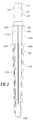
- Figures 2 , 3A , and 3B depict a front view, a top view, and a top perspective view, respectively, of the distal stem 102.
- the distal stem 102 includes a tapered trunnion 110 and stem body 105.
- Figure 4 depicts a cross-sectional view of the tapered trunnion 110.
- the tapered trunnion 110 includes a proximal end 114, a distal end 116, and a longitudinal axis 113 (illustrated by a dashed line) extending therebetween.
- the tapered trunnion 110 also includes an inner cavity 120.
- the inner cavity 120 is defined by an interior surface 122 of the tapered trunnion 110.
- the inner cavity 120 extends from an opening 124 at the proximal end 114 of the tapered trunnion 110 at least partially toward the distal end 116 of the tapered trunnion 110 through at least a portion of the tapered trunnion 110.
- the interior surface 122 of the tapered trunnion 110 includes a threaded portion 126 having one or more threads or grooves for receiving the fastener 106.
- the tapered trunnion 110 further includes an exterior surface section 130 near the proximal end of the tapered trunnion 110 configured to be received by the proximal body 104.
- the exterior surface section 130 is sized and/or shaped to securably engage the proximal body 104.
- the exterior surface section 130 can be substantially cylindrical.
- the stem body 105 includes first body section 112a and a second body section 112b.
- the second body section 112b includes a proximal end 132a, a distal end 132b, and a longitudinal axis 115a (illustrated by a dashed line) extending therebetween.
- the second body section 112b extends distally from the distal end 116 of the tapered trunnion 110.
- the longitudinal axis of the second body section 112b is aligned with or generally aligned with the longitudinal axis of the tapered trunnion 110.
- the first body section 112a includes a proximal end 134a, a distal end 134b, and a longitudinal axis 115b (illustrated by a dashed line) extending therebetween.
- the first body section 112a extends distally from the distal end 132b of the second body section 112b.
- the stem body 105 can be shaped and/or sized to allow the stem body 105 to be received within a femoral canal of various sizes for different patients.
- the second body section 112b can have a generally uniform cross-section along the axis 115a. In some embodiments, the second body section 112b can be generally cylindrical.
- the stem body 105 can have a length of 120mm, 130mm, 170mm, 210mm, or any other suitable size for implantation into the femoral canal. Some examples of these sized stem bodies are described in reference to Figures 13-16 .
- the first body section 112a can have a length of 120mm or 130mm. In some other examples, the first body section 112a can have a length any other suitable size.
- the first body section 112a may be tapered such that a first circumference or cross-sectional area of the second body section 112a perpendicular to the longitudinal axis 115b of the first body section 112a is smaller than a second circumference or cross-sectional area of the first body section 112a perpendicular to the longitudinal axis positioned proximal to the first circumference or cross sectional area of the first body section 112a.
- the first body section 112a tapers at a 3° angle from the proximal end 134a to the distal end 134b of the first body section 112a.
- the stem body 105 may be fluted having structural features that extend outward (or inward) from a surface of the stem body 105.
- the stem body may include one or more ridges or fins 150 (both being referred to as "fins" for ease of reference) extending longitudinally along the stem body 105.
- fins both being referred to as "fins” for ease of reference
- the fins 150 provide a separation between a surface of the femoral canal and the stem body 105 such that a space is formed, which may allow growth of bone or tissue around the distal stem 102 to help secure the distal stem 102 to the femoral canal.
- only a portion of the body 105 may include one or more fins 150.
- the first body section 112a includes one or more fins 150.
- a second body section 112b having fins 150 and having a total diameter measurement that includes the length of the fins 150 may be structurally weaker than a second body section 112b without fins and having a diameter equivalent to the total diameter measurement diameter measurement of the second body section 112b having fins 150.
- the second body section 112b may be provided without fins 150 in order to provide a smaller diameter of the second body section 112b while maintaining structural stability. Examples of embodiments having a second body section 112b without fins 150 are described with respect to Figures 15A-E below.
- only the second body section 112b includes one or more fins 150.
- one or more fins extend from the proximal end 132a of the second body section 112b to the distal end 134b of the first body section 112a.
- one or more fins extend from a segment of the distal stem 102 that is 25mm distal from the proximal end 114 to the distal end of the first body section 112a.
- the distal stem 102 may not have fins positioned between the proximal end 114 and a segment of the distal stem 102 that is 25mm distal from the proximal end 114.
- the distal stem 102 is sized such that there is an interference of .20mm radially between the fins 112 and the interior surface of the canal.
- the outer most diameter of the fins 150 is larger than the reamed canal, for example by 0.40mm (0.20mm radially).
- the fins 150 can have a fin height beyond the core diameter (the diameter of the stem body at sections that do not include fins 150) of, for example, 0.5mm, 0.68mm, 0.95mm, 1.0mm, 1.5mm, or another suitable height.
- the built-in interference e.g., of 0.20 mm radially affects the height of the distal stem 102 is final depth when fully seated.
- the 0.20mm nominal interference and having tight tolerance controls between the stem and reamer may yield a full seating range of -2.0mm to 4.0mm (that is, a 6.0mm range) where the distal stem 102 may sit below or above the top of the reamed canal, or slightly projecting above of reamed canal.
- the -2.0mm to 4.0mm e.g., a 6.0 mm range
- a tolerance of the distal stem 102 implant and the reamer used for example, providing a worst case of least material and maximum material conditions).
- the core diameter of stem body 105 at or near the proximal end of 134a of the first body section 112a can be 14.5mm, 15.5mm, 16.0mm. 16.5mm, 17.0mm, 17.5mm, 18.0mm, 18.5mm, 19.0mm, 20.0mm, 20.5mm, 21.0mm, 22.0mm, 23.0mm, 24.0mm, 25.0mm, 27.0mm or any other suitable diameter.
- the core diameter of stem body 105 at a point 65mm or about 65mm proximal to the distal end 134b can be 11.2mm, 12.2mm, 12.6mm, 13.6mm, 14.6mm, 15.6mm, 17.6mm, 19.6mm, 21.6mm, 23.6mm or any other suitable diameter.
- the core diameter at a point 11.1mm, 12.4mm, 13.7mm, 15.0mm, 16.3mm, 17.6mm, 18.9mm, 21.4mm, 24.0mm, 26.6mm, or 29.2mm proximal to the distal end 134b of the first body section 112a can be 7.9mm, 9.0mm, 9.0mm, 11.0mm, 12.1mm, 13.2mm, 15.3mm, 17.5mm, 19.6mm, 21.7mm, or any other suitable diameter.
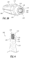
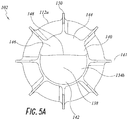
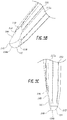
- Figures 5A-C depict a front view, a perspective view, and a side view, respectively of a section of the first body section 112a near the distal end 134b of the first body section 112a in accordance with some embodiments.
- the distal end 134b of the first body section 112a can include a distal tip 138.
- the distal tip 138 can be shaped and/or sized to facilitate introduction into or fit within the femoral canal.
- the distal tip 138 is shaped and/or sized to reduce impact and/or friction with an interior wall of the femoral canal during and/or after introduction of the distal stem 102.
- the distal tip 138 can be partially rounded.
- the distal tip 138 can be partially spherical in shape.
- the distal tip 138 includes a front section 140 and a rear section 142.
- the front section 140 and rear section 142 are separated by a coronal plane 141 (illustrated by a dashed line) extending through the first body section 112a from the proximal end 134a of the first body section 112a (not shown in Figures 4 and 5 ) to the distal end 134b of the first body section 112a.
- the rear section 142 of the distal tip 138 can be characterized by a partially rounded shape.
- the rear section 142 of the distal tip 138 can be partially spherical.
- At least a portion of the rear section 142 is shaped as a quarter sphere.
- a distal segment of the first body section 112a of the distal stem 102 is configured to taper towards the distal end 134b at a greater angle than a segment of the first body section 112a immediately proximal to the distal section.
- the front section 140 of the distal tip 138 includes an anterior relief 144.
- the anterior relief 144 can be shaped and/or sized to facilitate introduction into or fit within the femoral canal.
- the distal tip 138 is shaped and/or sized to reduce impact and/or friction within an interior wall of the femoral canal during and/or after introduction of the distal stem 102 into the femoral canal.
- the anterior relief 144 includes an elongated face 146.
- the elongated face 146 of the anterior relief 144 includes a rounded distal edge 148 at its distal most end.
- the elongated face 146 of the anterior relief 144 can extend to the distal end 134b of the first body section 112a or immediately proximal to the distal end 134b of the first body section 112a. In some embodiments, at least a portion of the anterior relief 144 is configured to taper towards the distal end 134b of the first body section 112a at a greater angle than a segment of the first body section 112a immediately proximal to the anterior relief 144.
- the anterior relief 144 can be any shape suitable for introduction into and residence within the femoral canal.
- the anterior relief 144 can be shaped to conform to the interior surface of the femur defining the femoral canal.
- the elongated face 146 of the anterior relief 144 can be substantially flat.
- the elongated face 146 can be circular, oval-shaped, diamond-shaped, square, triangular, or any other suitable shape.
- the anterior relief 144 is at least partially convex along a cross-section perpendicular to the longitudinal axis of the first body section 112a.
- the anterior relief 144 is at least partially concave along a cross-section perpendicular to the longitudinal axis of the first body section 112a. In some embodiments, the anterior relief 144 is at least partially concave along a cross-section parallel to the longitudinal axis of the first body section 112a. In some embodiments, the anterior relief 144 is at least partially concave along a cross-section parallel to the longitudinal axis of the first body section 112a. In some embodiments, the elongated face 146 of the anterior relief 144 can have a length of 38.1mm, 50.8mm, or any other suitable length.
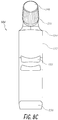
- FIGS. 6-8C depict a front perspective view, a bottom perspective view, and a top perspective view, respectively, of the proximal body 104 in accordance with some embodiments.
- the proximal body 104 includes a connection portion 152 and the neck portion 108.
- the connection portion 152 includes a proximal end 154, a distal end 156, and a longitudinal axis 111 (illustrated by a dotted line) extending therebetween.
- the distal end 156 of the connection portion 152 is configured to engage the proximal end 114 of the tapered trunnion 110 of the distal stem 102.
- connection portion 152 includes a first opening 158 configured to receive the proximal end 114 of the tapered trunnion 110.
- connection portion 152 also includes a second opening 160 at the proximal end 154 of the connection portion 152.
- the second opening 160 is configured to receive the fastener 106.
- connection portion 152 of the proximal body 104 further includes an inner cavity 162 extending between the first opening 158 and the second opening 160.
- the inner cavity 162 is defined by an interior surface 164 of the connection portion 152.
- the interior surface 164 includes one or more interior surface sections defining one or more inner cavity sections.
- the one or more interior surface sections can include one or more different circumferences, diameters, cross-sections, and/or surface features, such as for example, threading, grooves, or textured sections.
- the interior surface 164 of the connection portion 152 includes a first interior surface section 166 defining a first inner cavity section 168 positioned immediately proximal to the first opening 158 of the connection portion 152 of the proximal body 104.
- the first inner cavity section 168 is shaped and/or sized to receive the proximal end 114 of the tapered trunnion 110 of the distal stem 102.
- the first inner cavity section 168 is shaped/and or sized to facilitate mating of the first interior surface section 166 with the exterior surface section 130 of the tapered trunnion 110 of the distal stem 102.
- the first interior surface section 166 is configured to securably engage the exterior surface section 130 of the tapered trunnion 110 of the distal stem 102.
- the first interior surface section 166 can be configured to engage the exterior surface section 130 via an interference fit.
- the first interior surface section 166 and exterior surface section 130 can each include complimentary threaded portions.
- the inner cavity 162 includes a second interior surface section 170 immediately proximal the first interior surface section 166, the second interior surface section 170 defining a second inner cavity section 172.
- the second inner cavity section 172 has a circumference or cross-sectional area smaller than the circumference or cross-sectional area of the first inner cavity section 168. Accordingly, a circumference of the second interior surface section 170 is less than a circumference of the first interior surface section 166.
- a distal end of the second interior surface section 170 defines a lip 174.
- the circumference of the second interior surface section 170 is less than an outer circumference of the proximal end 114 of the tapered trunnion 110 of the distal stem 102.
- the proximal end 114 of the tapered trunnion 110 can be configured to abut the lip 174 defined by the distal end of the second interior surface section 170.
- the second inner cavity section 172 is configured to receive the fastener 106.
- the second inner cavity section 172 is sized and/or shaped to allow passage of at least a portion of the fastener 106 through the second inner cavity section 172 to at least a portion of the first inner cavity section 168.
- the second inner cavity section 172 includes a threaded section 176.
- the threaded section 176 includes one or more threads, grooves or other surface features configured to engage with one or more complimentary threads, grooves, or other surface features of a tool, fastener, or other device inserted into the second opening 160 of the connection portion 152.
- the threaded section 176 is configured to mate with a threaded section of a taper breaker.
- the threaded section 176 can be configured to mate with at least a portion of the threaded section of the fastener 106.
- the inner cavity 162 further includes a third interior surface section 178 extending distally from the second opening 160 and defining a third inner cavity section 180.
- the third interior section 178 can be positioned immediately proximal the second interior surface section 170.
- the third inner cavity section 180 is sized and/or shaped to receive a fastener, a tool, and/or one or more other devices.
- the third inner cavity section 180 is configured to allow for passage of portion of the fastener 106.
- the third inner cavity section 180 has a circumference or cross-sectional area greater than the circumference or cross-sectional area of the second inner cavity section 172. Accordingly, a circumference of the third interior surface section 178 can be greater than the circumference of the first interior surface section 166. In some embodiments, a proximal end of the second interior surface section 170 defines a spherical rim 182. The circumference of the second interior surface section 170 can be less than an outer circumference of at least a portion of the fastener 106.
- the spherical rim 182 defined by the proximal end of the second interior surface section 170 can be configured to abut at least a portion of the fastener 106 when the fastener 106 is inserted into the proximal body 104.
- the spherical rim 182 defined by the proximal end of the second interior surface section 170 can include one or more recesses or other surface features for receiving one or more tools or other devices, such as for example, a taper breaker.
- the second opening 160, third inner cavity section 180, and second inner cavity section 172 are configured to allow for passage of a portion of the fastener 106 so that the fastener 106 can securably mate with the distal stem 102 and to prevent a passage of a portion of the fastener 106 into the second inner cavity section 172 such that the fastener 106 secures the proximal body 104 to distal stem 102.
- the neck portion 108 of the proximal body 104 extends laterally and proximally from a side of the proximal body 104 and comprises a longitudinal axis 107 (illustrated by a dotted line).
- the neck portion 108 can be configured to engage a femoral head.
- the neck portion 108 can include a grooved section 151 having one or more grooves, threads, or other surface features configured to mate with a femoral head, such as femoral head 101.
- the grooved section 151 is configured to mate with a femoral head, such as femoral head 101 via a taper fit.
- the proximal body 104 may include one or more structures that are configured to be a connection place for securing a cable to the proximal body 104.
- the proximal body 104 illustrated in Figure 6 further includes a pair of cable grooves 153 positioned on an edge 103 of the proximal body.
- the cable grooves 153 extend into a portion of the surface 157 of the connection section 152.
- each cable groove 153 may be characterized as running along the generally cylindrical surface 157 of the connection section 152 in a plane that may be substantially normal to the longitudinal axis of the connection section 152.
- Each cable groove 153 can be configured to wrap partially around the exterior of the connection section 152. In some embodiments, each cable groove 153 can wrap around 5%, 10%, 15%, 20%, 25%, 30%, 35%, 40%, 50%, 55%, 60%, 65%, 70%, 75%, 80%, 85%, 90%, 95%, 100%, or any other suitable amount of the circumference of the connection section 152.
- the proximal body 104 can further include one or more cable grooves positioned on an opposite edge of the connection section 152 from the cable grooves 153 (not shown). Each of the cable grooves 153 can be configured to receive poly cabling.
- each of the cable grooves 153 can be configured to hold poly cabling (e.g., polymer cables) that is wrapped around the proximal body 104 and also around a portion of a patient's body so that the poly cabling does not move along the surface of the proximal body 104.
- poly cabling may be wrapped around the proximal body 104 and the patient's femur, and each of the cable grooves 153 receive a portion of the poly cabling in the groove 153 to secure the poly cabling from moving along a smooth, hard and curved surface of the proximal body. While two grooves are shown in Figure 6 , some embodiments may include a single groove, where other embodiments may include three, four, five, or more cable grooves.
- the cable grooves 153 are structured as an indentation (or channel) on a portion of the surface of the proximal body 104, having a selected depth and width to allow one or more cables to be placed in the cable groove.
- the cable grooves 153 are at least 0.01mm deep and at least 0.01mm wide.
- each cable groove 153 can have a different depth and width.
- the cable grooves 153 can have a depth of 0.70mm, 0.79mm, or any other suitable depth.
- the at least one groove is in the range of about 0.1mm to 0.8mm wide and/or about 0.1mm to 0.8mm deep, while in some embodiments the groves have a larger width and/or depth. In some embodiments, the grooves are normal to medial calcar surface or angles. In some embodiments, each groove is sized to receive two kinamed poly cables of 1.5mm (0.0625 inches) in diameter. In some embodiments, the at least one groove is 0.5mm (0.20 inches) deep and wide.
- the second inner cavity is configured to receive the threaded body of the fastener, wherein the interior surface of the proximal body at the second inner cavity includes a threaded section configured to mate with a threaded bolt of a taper breaker.
- the longitudinal axis of the tapered second body section is positioned at a non-zero angle to the longitudinal axis of the tapered trunnion.
- the size of the groove may be related to the size of the cable(s) deemed necessary to use based on the implementation. In some embodiments, the size of the groove can be used for a range of diameters of cables.
- the cable grooves 153 can have a width Wg of 0.76mm (0.03 inches). In some embodiments, the cable grooves 153 may have a depth of 0.76mm (0.03 inches). In most examples, the width Wg of each cable groove is greater than the length of the cable groove 153. In some embodiments, the cable grooves 153 are arranged normal to medial calcar surface or angles. Each cable groove 153 can be configured to receive one, two, three, four, five, or more poly cables. In some embodiments, each cable groove 153 is sized to receive two cables of about 1.58mm (0.0625 inches) diameter. Other sized grooves are also contemplated.
- each groove 153 a width and depth such that the function as a securing place for a cable such that the cable, when arranged to have at least a portion of the cable positioned in the groove, does not move along the proximal body 104 in a first direction 163 or a second direction 165 along the surface of the proximal body 104.
- the cables may be, for example, polymer cables made by Kinamed Inc., or other suitable cables.
- Figure 8D depicts a sectional view of the proximal body 104 including two poly cables 155 positioned within one of the grooves 153.
- Each poly cable 155 may have, for example, a diameter of 0.75mm, 0.76mm, 0.77mm, 0.78mm, 0.79mm, 0.80mm, 1.4mm, 1.5mm, 1.55mm, 1.56mm, 1.57mm, 1.58mm, 1.59mm 1.6mm, or any other suitable diameter.
- a length taken along the longitudinal axis 111 between the distal end 156 of the proximal body 104 and the lateral most point along the longitudinal axis 107 can be 62mm, 72mm, 82mm, or any other suitable length.
- An offset length of the proximal body 104 includes the lateral distance between the longitudinal axis 111 of the connection portion and the lateral most point along the longitudinal axis 107 of the neck portion 108. In some embodiments, the offset length can be 40mm, 45mm, or any other suitable length.
- the connection portion 104 can have a diameter of 20mm at a section distal to the neck portion 108.
- an angle between the longitudinal axis 111 and the longitudinal axis 107 can be 128°, 131°, or any other suitable angle.
- the length of the hip implant system 100 between the distal end 134b and the lateral most point of the neck portion 108 along the longitudinal axis 107 when the proximal body 104 is engaged with the distal stem 102 can be 195mm, 205mm, 215mm, 235mm, 245mm, 255mm, 275mm, 285mm, 295mm, or any other suitable length.
- a taper angle at the junction between the distal stem 102 and proximal body 104 can be 2°, 46', and 45".
- a taper angle at the junction between the neck portion 108 and the femoral head 101 can be 5°, 42' 30".
- Figures 9A and 9B depict a perspective view and a front view, respectively, of the fastener 106.
- the fastener 106 can be a locking bolt.
- the fastener 106 includes a head 184 and a threaded body 186.
- the head 184 may include a spherical portion 185 configured to engage the spherical rim 182 of the proximal body 104.
- the spherical portion 185 can be configured to conform to the shape of the spherical rim 182 in order restrict movement and/or provide stabilization in a lateral direction.
- the threaded body 186 includes distal end 188 having a threaded section 190 having one or more threads, grooves, or other surface features configured to mate with the threaded portion 126 of the interior surface 122 of the tapered trunnion 110 of the distal stem 102.
- the head 184 of the fastener 106 can be configured to be received in the third inner cavity section 180 of the proximal body 104. At least a portion of the head 184 of the fastener 106 can have a circumference or cross-sectional area less than the circumference or cross-sectional area of the third inner cavity section 180.
- At least a portion of the head 184 can have a circumference or cross-sectional area greater than the circumference or cross-sectional area of the second inner cavity section 172 such that spherical portion 185 of the head 184 can abut (or make contact with) the spherical rim 182 defined by the proximal end of the second interior surface section 170 of the connection portion 152 of the proximal body 104 when the fastener 106 is received within the proximal body 104.
- the surface of the spherical portion 185 of the head 184 contacts the surface of the spherical rim 182 to provide a shaped friction surface contact that helps prevent a tightly seated fastener 106 from loosening up over time and aligns and seats the fastener 106 into the proximal body 104.
- the threaded section 190 of the threaded body is configured to mate with the threaded section 190 of the interior surface 122 of the tapered trunnion 110 of the distal stem 102 such that the proximal end 114 of the tapered trunnion 110 of the distal stem 102 abuts the lip 174 defined by the distal end the second interior surface section 170 and a portion of the head 184 of the fastener 106 abuts the spherical rim 182 defined by the proximal end of the second interior surface section 170.
- the fastener can have a length of 65mm, 75mm, 85mm, or any other suitable length.
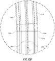
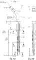
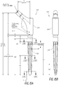
- Figures 10A and 10B depict a side view and a sectional view, respectively, of a distal stem 202 in accordance some embodiments.
- the distal stem 202 can include many of the same or similar features to the distal stem 102, described with respect to Figures 2-5c .
- the distal stem includes a tapered trunnion 210 having a proximal end 214, a distal end 216, and a longitudinal axis 213 (illustrated by a dashed line) extending therebetween.
- the tapered trunnion 210 can further include an inner cavity extending from an opening at the distal end 214 configured to receive a fastener, such as fastener 106.
- the distal stem 202 further includes a stem body 205.
- the stem body 205 includes a first body section 212a and a section body section 212b.
- the second body section 212b includes a proximal end 232a, a distal end 234b, and a longitudinal axis 215a extending therebetween.
- the second body section 212b extends distally from the distal end 216 of the tapered trunnion 210.
- the longitudinal axis 215a of the second body section 212b is aligned with or generally aligned with the longitudinal axis 213 of the tapered trunnion 210.
- the first body section 212a includes a proximal end 234a, a distal end 234b, and a longitudinal axis 215b (illustrated by a dashed line) extending therebetween.
- the first body section 212a extends distally from the distal end 232b of the second body section 212b.
- At least a portion of the first body section 212a is tapered such that a first circumference or cross-sectional area of the first body section 212a perpendicular to the longitudinal axis 215b of the first body section 212a is smaller than a second circumference or cross-sectional area of the first body section 212a perpendicular to the longitudinal axis 215b positioned proximal to the first circumference or cross sectional area.
- the first body section 212a further includes a distal tip 238.
- the distal tip 238 can be generally similar to the distal tip 138, described with respect to Figures 2-5 .
- the distal stem 202 has a "bowed" configuration.
- the longitudinal axis 215b of the first body section 212a is not exactly aligned to the longitudinal axis 215a of the second body section 212b such that the a single longitudinal axis is coincident with the longitudinal axis 215b of the first body section 212a and the longitudinal axis 215a of the second body section 212b. That is, the longitudinal axis 215b of the first body section 212a is positioned at a non-zero angle A to the longitudinal axis 215a of the second body section 212b to facilitate introduction and/or residence of the distal stem 202 into a femoral canal.
- the non-zero angle A can be, for example, a small angle including but not limited to 2 degrees, 3 degrees, 4 degrees, 5 degrees, or any other suitable angle.
- the bowed configuration of the distal stem 202 can reduce impact and/or friction on an interior surface defining the femoral canal by the distal stem 202 during introduction into or residence within the femoral canal.
- the stem body 505 further includes fins 550.
- the fins 550 can be similar, or the same, as the fins 150 described with respect to Figure 2-5 . As shown in Figures 10A and 10B , the fins 550 extend along the first body section 212a and the second body section 212b. However, in some embodiments, the fins may extend along only one of the first body section 212a and the second body section 212b.
- the stem body 205 can have a length of 120mm, 130mm, 170mm, 210mm, or any other suitable size for implantation into the femoral canal.
- the first body section 212a can have a length of 120mm, 130mm, or any other suitable size.
- the core diameter of stem body 205 at or near the proximal end of 234a of the first body section 212a can be 14.5mm, 15.5mm, 16.0mm. 16.5mm, 17.0mm, 17.5mm, 18.0mm, 18.5mm, 19.0mm, 20.0mm, 20.5mm, 21.0mm, 22.0mm, 23.0mm, 24.0mm, 25.0mm, 27.0mm or any other suitable diameter.
- the core diameter of stem body 205 at a point 65mm or about 65mm proximal to the distal end 234b can be 11.2mm, 12.2mm, 12.6mm, 13.6mm, 14.6mm, 15.6mm, 17.6mm, 19.6mm, 21.6mm, 23.6mm or any other suitable diameter.
- the core diameter at a point 11.1mm, 12.4mm, 13.7mm, 15.0mm, 16.3mm, 17.6mm, 18.9mm, 21.4mm, 24.0mm, 26.6mm, or 29.2mm proximal to the distal end 234b of the first body section 212a can be 7.9mm, 9.0mm, 9.0mm, 11.0mm, 12.1mm, 13.2mm, 15.3mm, 17.5mm, 19.6mm, 21.7mm, or any other suitable diameter.
- the first body section 212a tapers at a 3° angle from the proximal end 134a to the distal end 134b of the first body section 212a.
- Figure 11 depicts a cross-sectional view of a section of a hip implant system 300 in accordance with some embodiments.
- the hip implant system 300 includes a proximal body 304, distal stem 302, and a fastener 306.
- the distal stem 302 can include many of the same or similar features to the distal stems 102 and 202.
- Figure 11 shows a portion of a tapered trunnion 310 of the distal stem 302 having a proximal end 314, a distal end (not show), and a longitudinal axis extending therebetween.
- the tapered trunnion 310 includes a first exterior surface portion 330A extending from the proximal end 314 of the tapered trunnion 310 and a second exterior surface portion 330B, immediately distal to the first exterior surface portion 330A.
- the first exterior surface portion 330A includes a threaded section 326 configured to mate with a complementary threaded section of the fastener 306.
- the second exterior surface section 330B can have a circumference greater than that of the first exterior surface section 330A.
- the distal stem 302 further includes a stem body 305 having a third exterior surface portion 330C extending distally from the second exterior surface portion 330B, the third exterior surface portion 330C having a circumference or cross-sectional area greater than that of the second exterior surface portion 330B, such that a proximal end of the third exterior surface portion 330C defines a lip 406.
- the proximal body 304 includes a connection portion 352 and a neck portion 308.
- the connection portion 352 includes a proximal end 354 and a distal end 356.
- the distal end 356 of the connection portion 352 can be configured to engage the proximal end 314 of the tapered trunnion 310 of the distal stem 302.
- the distal end 356 of the connection portion 352 includes a first opening 358 configured to receive the proximal end 314 of the tapered trunnion 310.
- the connection portion 352 further includes a second opening 360 at the proximal end 354 of the connection portion 352.
- the second opening 360 can be configured to receive the fastener 306.
- connection portion 352 of the proximal body 304 further include an inner cavity 362 extending between the first opening 358 and the second opening 360.
- the inner cavity 362 is defined by an interior surface 364 of the connection section 352.
- the inner cavity 362 is configured to receive the first exterior surface portion 330A and at least a portion of the second exterior surface portion 330B of the tapered trunnion 310.
- the circumference or cross-sectional area of the second exterior surface portion 330B of the tapered trunnion 310 can be less than that of the circumference or cross-sectional area of the inner cavity 362.
- the interior surface 364 of the proximal body 304 can be configured to form an interference fit with the second exterior surface portion of the tapered trunnion 310.
- the second opening 360 of the connection portion 352 of the proximal body 304 can be configured to receive a portion of the fastener 306.
- the fastener 306 includes a proximal end 387 and a distal end 388.
- the fastener 306 further includes a mating portion 390.
- the mating portion 390 includes an inner cavity 392 defined by an interior surface 394 of the mating portion 390.
- the inner cavity 392 can extend from the distal end 388 of the fastener 306 at least partially toward the proximal end 387 of the fastener 306.
- the interior surface 394 of the mating portion 390 further includes a threaded section 396 configured to mate with the threaded section 326 of the first exterior surface portion 330A of the tapered trunnion 310 of the distal stem 302.
- An exterior surface 398 of the mating portion 390 of the fastener 306 can have a circumference or cross-sectional area less than the circumference or cross sectional area of the inner cavity 392, such that the mating portion 390 of the fastener 306 can be received within the inner cavity 362 of the proximal body 304.
- the fastener 306 further includes an inclined contact face 400 positioned proximal the mating portion 390.
- the inclined contact face 400 can extend proximally and laterally from the mating portion 390 such that the circumference of at least a portion of the inclined contact face 400 is greater than the circumference of the exterior surface 398 of the mating portion 390.
- the proximal end 354 of the connection portion 352 of the proximal body 304 also includes an inclined mating surface 402 configured to receive the inclined mating surface 400 of the fastener 306.
- the inclined mating surface 402 of the proximal body 304 has a circumference greater than the circumference of the interior surface 394 of the proximal body 304 immediately distal the inclined mating surface 402.
- This configuration allows the inclined mating surface 400 of the fastener 306 to abut the inclined mating surface 402 of the proximal body 304 when the threaded section 396 of the mating portion 390 of the fastener 306 is tightened to the threaded section 326 of first exterior surface portion 330A of the tapered trunnion 310 of the distal stem 302.
- the third exterior surface portion 330C of the tapered trunnion 310 of the distal stem 302 can have a circumference or cross-sectional area greater than that of the interior surface 394 of the proximal body 304, such that the lip 406 is configured to abut the distal end 356 of the proximal body 304 when the threaded section 396 of the mating portion 390 of the fastener 306 is tightened to the threaded section 326 of first exterior surface portion 330A of the tapered trunnion 310 of the distal stem 302.
- Figure 12 depicts a distal stem 502 in accordance some embodiments.
- the distal stem 502 can include many of the same or similar features to the distal stems 102. 202, and 302, described with respect to Figures 2-5 and 10A-11 .
- the distal stem includes a tapered trunnion 510 having a proximal end 514, a distal end 516, and a longitudinal axis 513 (illustrated as a dotted line) extending therebetween.
- the tapered trunnion 510 can further include an inner cavity extending from an opening at the distal end 514 configured to receive a fastener, such as fastener 106.
- the distal stem 502 further includes a stem body 505.
- the stem body 505 includes a proximal end 532, a distal end 534, and a longitudinal axis 515 extending therebetween.
- the stem body 505 extends distally from the distal end 516 of the tapered trunnion 510.
- the longitudinal axis 515 of the stem body 505 is aligned with or generally aligned with the longitudinal axis 513 of the tapered trunnion 510.
- the stem body 505 is tapered such that a first circumference or cross-sectional area of the stem body 505 perpendicular to the longitudinal axis 515 of the stem body 505 is smaller than a second circumference or cross-sectional area of the first body section 512 perpendicular to the longitudinal axis 515 positioned proximal to the first circumference or cross sectional area.
- the stem body 505 further includes a distal tip 538. In various embodiments, the distal tip 538 can be similar, or the same, as the distal tip 138 described with respect to Figures 2-5 .
- the stem body 505 further includes fins 550. In various embodiments, the fins 550 can be similar, or the same, as the fins 150 described with respect to Figure 2-5 .
- the stem body 505 can have a length of 120mm, 130mm, 170mm, 210mm, or any other suitable size for implantation into the femoral canal.
- the core diameter of stem body 505 at or near the proximal end 532 of the stem body 505 can be 14.5mm, 15.5mm, 16.0mm. 16.5mm, 17.0mm, 17.5mm, 18.0mm, 18.5mm, 19.0mm, 20.0mm, 20.5mm, 21.0mm, 22.0mm, 23.0mm, 24.0mm, 25.0mm, 27.0mm or any other suitable diameter.
- the core diameter of stem body 505 at a point 65mm or about 65mm proximal to the distal end 534 can be 11.2mm, 12.2mm, 12.6mm, 13.6mm, 14.6mm, 15.6mm, 17.6mm, 19.6mm, 21.6mm, 23.6mm or any other suitable diameter.
- the core diameter at a point 11.1mm, 12.4mm, 13.7mm, 15.0mm, 16.3mm, 17.6mm, 18.9mm, 21.4mm, 24.0mm, 26.6mm, or 29.2mm proximal to the distal end 234b of the first body section 212a can be 7.9mm, 9.0mm, 9.0mm, 11.0mm, 12.1mm, 13.2mm, 15.3mm, 17.5mm, 19.6mm, 21.7mm, or any other suitable diameter.
- the stem body 505 tapers at a 3° angle from the proximal end 534 to the distal end 534 of the first body section 505.
- Figures 13A-B depict a hip implant system 500 including an embodiment of the proximal body 104 and an embodiment of the distal stem 502.
- Figures 13C-E depict cross-sectional views of the embodiment of the distal stem 502 depicted in Figures 13A-B showing fins 550.
- Figure 13C depicts a cross-section of the distal stem 502 taken along line 13C-13C of Figure 13A .
- Figure 13D depicts a cross-section of the distal stem 502 taken along line 13D-13D of Figure 13A .
- Figure 13E depicts a cross-section of the distal stem 502 taken along line 13E-13Eof Figure 13A .
- Tables 1 and 2 provide example values of a length A of the proximal body 104, an Offset B of the proximal body 104, a Total Length C of the implant system 500, an angle D between the longitudinal axis of the connection portion of the proximal body 104 and the longitudinal axis of the neck portion of the proximal body 104, a length E of a section of the distal stem 502, a diameter K of a section of the tapered trunnion of the distal stem 502, a length L of a section of the distal stem 102, a core diameter G of the distal stem 502 along line 13C-13C, a fin height F of the distal stem 502 along line 13C-13C, a core diameter H of the distal stem 502 along line 13D-13D, a fin height F of the distal stem 502 along line 13D-13D, a core diameter J of the distal stem 502 along line 13E-13E, a fin height F of the distal stem 50
- the length E represents a segment of the distal stem 502 that tapers towards the distal end 534 of the distal stem 502 at a greater angle than the taper of the segment of the distal stem 502 proximal to the segment represented by the length E.
- a first amount (or angle) of taper where the core diameter of the distal stem 502 (at least in one cross-sectional direction) is decreasing at a first rate (e.g., as a function of distance along the distal stem 502).
- the core diameter of the of the distal stem 502 decreases at a second rate (e.g., as a function of distance along the length of the distal stem 502 from line 13C-13C to the distal stem), such that there is two different tapers along the length E of the distal stem 502.
- a second rate e.g., as a function of distance along the length of the distal stem 502 from line 13C-13C to the distal stem
- Other examples may also have more than one taper amount along the distal stem, for example, as illustrated in Figures 14 , 15 and 16 .
- Figures 14A-B depict an example of a hip implant system 100 including an embodiment of the proximal body 104 and an embodiment of the distal stem 102. Figures 14A-B do not show the femoral head 101 of the hip implant system 100.
- Figures 14C-E depict cross-sectional views of the embodiment of the distal stem 102 depicted in Figures 14A-B showing fins 150.
- Figure 14C depicts a cross-section of the distal stem 102 taken along line 14C-14C of Figure 14A .
- Figure 14D depicts a cross-section of the distal stem 102 taken along line 14D-14D of Figure 14A .
- Figure 14E depicts a cross-section of the distal stem 102 taken along line 14E-14E of Figure 14A .
- Tables 3 and 4 provide example values of a length A of the proximal body 104, an Offset B of the proximal body 104, a Total Length C of the proximal body 104 and the distal stem 102 of the implant system 100, an angle D between the longitudinal axis of the connection portion of the proximal body 104 and the longitudinal axis of the neck portion of the proximal body 104, a length E of a section of the distal stem 102, a length K of a section of the distal stem 102, a core diameter G of the distal stem 102 along line 14C-14C, a fin height F of the distal stem 102 along line 14C-14C, a core diameter H of the distal stem 102 along line 14D-14D, a fin height F of the distal stem 102 along line 14D-14D, a core diameter J of the distal stem 102 along line 14E-14E, a fin height F of the distal stem 102 along line 14E-14E,
- the length E represents a segment of the distal stem 102 that tapers towards the distal end of the distal stem 102 at a greater angle than the segment of the distal stem 102 proximal to the segment represented by the length E.
- Table 3 PROXIMAL BODY OFFSET 'A' (mm) 'B' (mm) 'C' (mm) 'D' (deg) 65 STD 62 40 235 131 LAT 45 128 75 STD 72 40 245 131 LAT 45 128 85 STD 82 40 255 131 LAT 45 128 Table 4 Stem Size 'E' (mm) 'F' (mm) 'G' (mm) 9.9 'H' (mm) 'J' (mm) 'K' (mm) 16 ⁇ 170 13.7 1.0 12.6 16.0 38.1 17x170 15.0 1.0 11.0 13.6 17.0 38.1 18 ⁇ 170 16.3 1.5 11.0 13.6 17.0 50.8 19 ⁇ 170 17.6 1.5 12.1 14.6 18.0 50.8 20x
- Figures 15A-B depict an example of a hip implant system 100 including an embodiment of the proximal body 104 and an embodiment of the distal stem 102. Figures 15A-B do not show the femoral head 101 of the hip implant system 100.
- Figures 15C-E depict cross-sectional views of the embodiment of the distal stem 102 depicted in Figures 15A-B showing fins 150.
- Figure 15C depicts a cross-section of the distal stem 102 taken along line 15C-15C of Figure 15A .
- Figure 15D depicts a cross-section of the distal stem 102 taken along line 15D-15D of Figure 15A .
- Figure 15E depicts a cross-section of the distal stem 102 taken along line 15E-15E of Figure 15A .
- Tables 5 and 6 provide example values of a length A of the proximal body 104, an Offset B of the proximal body 104, an angle C between the longitudinal axis of the connection portion of the proximal body 104 and the longitudinal axis of the neck portion of the proximal body 104, a stem length D of the distal stem 102, a total length E of the proximal body 104 and distal stem 102 of the implant system 100, a length F of a section of the distal stem 102, a length M of a section of the distal stem 102, a core diameter G of the distal stem 102 along line 15C-15C, a fin height K of the distal stem 102 along line 15C-15C, a core diameter H of the distal stem 102 along line 15D-15D, a fin height L of the distal stem 102 along line 15D-15D, a core diameter J of the distal stem 102 along line 15E-15E as shown in Figures 15A-E
- the height of the fins 150 can decrease from the distal end of the distal stem 102 towards the proximal end of the distal stem 102.
- the length F represents a segment of the distal stem 102 that tapers towards the distal end of the distal stem 102 at a greater angle than the segment of the distal stem 102 proximal to the segment represented by the length E.
- Figure 16A depicts an example of a hip implant system 200 including an embodiment of the proximal body 104 and an embodiment of the distal stem 202.
- Figures 16B-D depict cross-sectional views of the embodiment of the distal stem 202 depicted in Figure 16A showing fins 250.
- Figure 16B depicts a cross-section of the distal stem 202 taken along line 16B-16B of Figure 16A .
- Figure 16C depicts a cross-section of the distal stem 202 taken along line 16C-16C of Figure 16A .
- Figure 16D depicts a cross-section of the distal stem 202 taken along line 16D-16D of Figure 14A .
- Tables 7 and 8 provide example values of a length A of the proximal body 104, an Offset B of the proximal body 104, a Total Length C of the implant system 200, an angle D between the longitudinal axis of the connection portion of the proximal body 104 and the longitudinal axis of the neck portion of the proximal body 104, a length K of a section of the distal stem 202, a core diameter F of the distal stem 202 along line 16B-16B, a fin height E of the distal stem 202 along line 16B-16B, a core diameter G of the distal stem 202 along line 16C-16C, a fin height E of the distal stem 202 along line 16C-16C, a core diameter H of the distal stem 202 along line 16D-16D, a fin height E of the distal stem 202 along line 16D-16D, as shown in Figures 16A-D .
- the length K represents a segment of the distal stem 202 that tapers towards the distal end of the distal stem 202 at a greater angle than the segment of the distal stem 202 proximal to the segment represented by the length K.
- Table 7 PEOXIMAL BODY OFFSET 'A' (mm) 'B'(mm) 'C' (mm) 'D' (deg) 65 STD 62 40 275 131 LAT 45 128 75 STD 72 40 28 5 131 LAT 45 128 85 STD 82 40 295 131 LAT 45 128 Table 8 Stem Size 'E' (mm) 'F' (mm) 'G' (mm) 'H' (mm) 'J' (mm) 16 ⁇ 210 13.7 1.0 9.9 12.6 16.0 38.1 17 ⁇ 210 15.0 1.0 11.0 13.6 11.0 38.1 18 ⁇ 210 16.3 1.5 11.0 13.6.
- Figure 17 depicts an embodiment of the hip implant system 100 in combination poly cables 155 positioned within a femoral canal.
- Two poly cables 155 are wrapped around each cable groove 153 of the proximal body 104 and around a section of the femur opposite the cable grooves 153.
- the cable grooves 153 can be configured to prevent slippage of the poly cables 155 along the proximal body 104.
- the poly cables 155 can be wrapped around the proximal body 104 and the femur to restrict or prevent relative movement of the proximal body 104 with respect to the femur.
- Figure 18 depicts an embodiment of the hip implant system 500 in combination with a femoral head 101 positioned within a body of patient.
- the distal stem 102 is positioned with a femoral canal of a femur of a right leg of the patient.
- the proximal body 104 is oriented so that the neck of the proximal body 104 extends medially towards an acetabulum on the right side of the pelvis of the patient.
- the outer diameter of the longitudinal fins are larger than the corresponding reamed hole.
- the fins interfere with (that is, extend into or "bite” into) the cortical wall of the reamed bone by an amount equal to or less than the height of the fins.
- at least a portion of the fins extend into the cortical wall by (radially) 0.10mm or less, 0.20mm or less, or up to the amount of the fin height.
- the at least a portion of the fins may extend into the cortical wall by 0.20mm radially (diametrically 0.40mm, that is, 0.20mm per side).
- the hip implant systems described herein can be made of any material suitable for implant into the human body.
- the components of the hip implant systems described herein can be variously sized or shaped, in addition to what is explicitly describe herein, to increase their functionality and/or suitability for hip replacement.
- the length of the distal stem can be 130mm, 170mm, 210mm, less than 130mm, between 130mm to 170mm, between 170mm to 210mm, greater than 210mm, or any other suitable length.
- hip implant systems described herein can be utilized to treat a variety of hip issues including, but not limited to, non-inflammatory degenerative joint disease, including osteoarthritis and avascular necrosis of the natural femoral head, rheumatoid arthritis, functional deformities, femoral fracture, trochanteric fracture, and previously failed surgical attempts.
- non-inflammatory degenerative joint disease including osteoarthritis and avascular necrosis of the natural femoral head, rheumatoid arthritis, functional deformities, femoral fracture, trochanteric fracture, and previously failed surgical attempts.
- An exemplary method of implanting the hip implant systems described herein can include one or more of the following steps.
- the femur of a patient can be reamed until cortical chatter is detected at a depth corresponding to a desired stem length.
- the femur can be reamed sequentially using reamers of increasing size.
- the femoral canal can be evaluated for positioning of an anterior relief of a distal stem of the hip implant system.
- the distal stem of the hip implant system can be inserted into the femoral canal.
- the anterior relief can be positioned to accommodate the shape of an interior wall of the femoral canal.
- a proximal body reamer can be used to remove bone at the medial base of the greater trochanter to facilitate trialing and implanting of a proximal body of the hip implant system.
- a trial proximal body can be secured to the implanted stem.
- the range of motion and stability using the trial proximal body can be assessed. If the trial proximal body provides a desired range of motion and stability, the trial proximal body can be implanted and secured with a fastener. If the trial proximal body does not provide the desired range of motion and stability, the trial proximal body can be removed and replaced with additional proximal bodies until a desired match is found.
- Couple may indicate either an indirect connection or a direct connection.
- first component may be either indirectly connected to the second component or directly connected to the second component.
- plurality denotes two or more. For example, a plurality of components indicates two or more components.
Landscapes
- Health & Medical Sciences (AREA)
- Orthopedic Medicine & Surgery (AREA)
- Cardiology (AREA)
- Oral & Maxillofacial Surgery (AREA)
- Transplantation (AREA)
- Engineering & Computer Science (AREA)
- Biomedical Technology (AREA)
- Heart & Thoracic Surgery (AREA)
- Vascular Medicine (AREA)
- Life Sciences & Earth Sciences (AREA)
- Animal Behavior & Ethology (AREA)
- General Health & Medical Sciences (AREA)
- Public Health (AREA)
- Veterinary Medicine (AREA)
- Prostheses (AREA)
Description
- This invention generally relates to prosthetic implants for both primary and revision hip applications. More specifically, this invention generally relates to systems of prosthetic implants, for example, systems that may include a stem, a proximal body, and a fastener, such as disclosed in document
FR 2983061 A - A damaged hip joint can cause pain and decreased mobility and may necessitate hip replacement surgery. Hip replacement surgery involves removal of at least part of a hip joint and replacement with a prosthetic implant. In a partial hip replacement surgery, or hemiarthroplasty, the femoral head of a damaged hip joint is removed and replaced with a prosthetic implant. In a total hip replacement surgery, both the femoral head and the acetabulum of the damaged hip joint are replaced. With revision total hip replacement surgery, it is common practice to remove the primary implants due to wear & tear, loosening infection or leg length discrepancies with primary surgery. Upon removal of the primary implants the remaining proximal femur is carefully machined (refined) to accept revision implant components. Modular, tapered revision stems (Wagner-style) have begun the popular implant choice as it accommodates diaphysis fixation while accommodating proximal stem-trunnion position via modular adjustments.
- A prosthetic implant for hip replacement surgery can include a femoral stem component, a femoral head component, and, in instances of total hip replacement, an acetabular component. The femoral head component connects to the femoral stem component and can be secured to the femur by introduction of the femoral stem component into a femoral canal after the head and neck of the femur have been removed and the femoral canal has been reamed. The femoral head component is positioned to engage the acetabulum or, in instances of total hip replacement, the acetabular component that is attached to the acetabulum following removal of undesired portions. The size of the femoral canal, even when reamed, it limited by it structure, where enlarging it too much weakens the walls of the femur surrounding the femoral canal. Improvements on the structure of femoral stem component are desired to help alleviate the amount of reaming of the femoral canal.
- The invention is defined in
claim 1 and illustrated in particular infigures 6 to 9 . Several innovations are disclosed herein, each having multiple aspects that can be included in various embodiments of the innovations. - The distal stem can include a plurality of ridges disposed on the exterior surface of the stem body. The distal end of the stem body can include a partially rounded distal tip including a front section and a rear section, the front and rear sections separated by a coronal plane extending through the stem body from a proximal end of the stem body to the distal end of the stem body, wherein the rear section of the distal tip is characterized by a partially spherical shape, wherein the front section of the distal tip includes an anterior relief having an elongated face having a rounded distal edge, wherein at least a portion of the anterior relief is configured to taper towards the distal end at a greater angle than a segment of the stem body immediately proximal to the anterior relief. In some examples, the exterior surface of the proximal body includes at least one groove configured to receive poly cabling (such a groove may be referred to herein as a "cable groove" for ease of reference). The cable groove is useful, for example, as a structure to hold poly cabling that is wrapped around the proximal body and also around a portion of a patient's body so that the poly cabling does not move along the surface of the proximal body. For example, poly cabling may be wrapped around the proximal body and the patient's femur, and the cable groove receives a portion of the poly cabling in the groove to secure the poly cabling from moving along a smooth, hard and curved surface of the proximal body. Some examples may include a single groove, where other embodiments may include 2, 3, 4, 5 or more cable grooves. The cable groove is structured as an indentation (or channel) on a portion of the surface of the proximal body, having a selected depth and width to allow one or more cables to be placed in the cable groove. In some examples, the at least one groove is at least 0.01mm deep and at least 0.01mm wide, although in many applications the at least one groove is much larger, for example, in the range of about 0.1mm to 0.8mm (wide and/or deep). In some examples, the grooves are normal to medial calcar surface or angles. In some examples, each groove is sized to receive two kinamed poly cables of 1.5mm (0.0625 inches) in diameter. In some examples, the at least one groove is 0.5mm (0.20 inches) deep and wide. In some examples, the second inner cavity is configured to receive the threaded body of the fastener, wherein the interior surface of the proximal body at the second inner cavity includes a threaded section configured to mate with a threaded bolt of a taper breaker. In some examples, the longitudinal axis of the stem body is positioned at a non-zero angle to the longitudinal axis of the tapered trunnion.
- In some examples, the distal stem may include a plurality of ridges disposed on the exterior surface of the stem body. In some examples, the distal end of the stem body includes a partially rounded distal tip having a front section and a rear section, the front and rear sections being separated by a coronal plane extending through the stem body from a proximal end of the stem body to the distal end of the stem body. The rear section of the distal tip may be characterized by a partially spherical shape, wherein the front section of the distal tip includes an anterior relief, the anterior relief having an elongated face having a rounded distal edge. At least a portion of the anterior relief may be configured to taper towards the distal end at a greater angle than a segment of the stem body immediately proximal to the anterior relief. In some embodiments, an exterior surface of the proximal body includes at least one groove configured to receive poly cabling. In some embodiments, the longitudinal axis of the stem body is positioned at a non-zero angle to the longitudinal axis of the tapered trunnion.
-
-
Figure 1 depicts a front view of a hip implant system. -
Figure 2 depicts a front view of a distal stem. -
Figure 3A depicts a top view of a distal stem. -
Figure 3B depicts a top perspective view of a distal stem. -
Figure 4 depicts a cross-sectional view of a section of a distal stem. -
Figure 5A depicts a bottom view of a distal stem. -
Figure 5B depicts a front perspective view of a section of a distal stem. -
Figure 5C depicts a side view of a section of a distal stem. -
Figure 6 depicts a front perspective view of a proximal body in accordance with an illustrative embodiment. -
Figure 7 depicts a cross-sectional view of a proximal body in accordance with an illustrative embodiment. -
Figure 8A depicts a bottom perspective view of a proximal body in accordance with an illustrative embodiment. -
Figure 8B depicts a top perspective view of a proximal body in accordance with an illustrative embodiment. -
Figure 8C depicts a side view of a proximal body in accordance with an illustrative embodiment. -
Figure 8D depicts a cross-sectional view of a section of a proximal body in accordance with an illustrative embodiment. -
Figure 9A depicts a perspective view of a fastener in accordance with an illustrative embodiment. -
Figure 9B depicts a front view of a fastener in accordance with an illustrative embodiment. -
Figure 10A depicts a side view of a distal stem. -
Figure 10B depicts a sectional view of an enlarged section of a distal stem. -
Figure 11 depicts a cross-sectional view of a section of a hip implant system. -
Figure 12 depicts front view of a distal stem. -
Figure 13A depicts a front view a hip implant system. -
Figure 13B depicts a side view of a hip implant system. -
Figure 13C depicts a cross-sectional view of a distal stem. -
Figure 13D depicts a cross-sectional view of a distal stem. -
Figure 13E depicts a cross-sectional view of a distal stem. -
Figure 14A depicts a front view a hip implant system. -
Figure 14B depicts a side view of a hip implant system. -
Figure 14C depicts a cross-sectional view of a distal stem. -
Figure 14D depicts a cross-sectional view of a distal stem. -
Figure 14E depicts a cross-sectional view of a distal stem. -
Figure 15A depicts a front view a hip implant system. -
Figure 15B depicts a side view of a hip implant system. -
Figure 15C depicts a cross-sectional view of a distal stem. -
Figure 15D depicts a cross-sectional view of a distal stem. -
Figure 15E depicts a cross-sectional view of a distal stem. -
Figure 16A depicts a front view a hip implant system. -
Figure 16B depicts a cross-sectional view of a distal stem. -
Figure 16C depicts a cross-sectional view of a distal stem. -
Figure 16D depicts a cross-sectional view of a distal stem. -
Figure 17 depicts a front view of a hip implant system positioned within a femur. -
Figure 18 depicts a front view of a hip implant system positioned within a body. - The following detailed description is directed to certain specific embodiments of the invention. However, the invention can be embodied in a multitude of different ways. It should be apparent that the aspects herein may be embodied in a wide variety of forms and that any specific structure, function, or both being disclosed herein is merely representative of one or more embodiments of the invention. An aspect disclosed herein may be implemented independently of any other aspects and that two or more of these aspects may be combined in various ways. For example, an apparatus (e.g., the illustrated embodiments a distal stem or a proximal body) may be implemented, or a method may be practiced, using any number of the aspects set forth herein. In addition, such an apparatus may be implemented or such a method may be practiced using other structure, functionality, or structure and functionality in addition to, or other than one or more of the aspects set forth herein.
-
Figure 1 depicts an example of ahip implant system 100, in accordance with some embodiments. The illustratedhip implant system 100 includes an elongated distal stem 102 (sometimes referred to herein as "distal stem" for ease of reference), aproximal body 104, afastener 106, and afemoral head 101. Reference to a "hip implant system" as used herein generally refers to at least two components, for example, a hip implant system as referred to herein may include theproximal body 104 and the elongateddistal stem 102. In another example, a hip implant system as referred to herein may include theproximal body 104, the elongateddistal stem 102, and thefastener 106. - The
hip implant system 100 can be configured for placement in the human body as part of a partial or total hip replacement surgery to replace at least part of a damaged hip joint. Thedistal stem 102 can securably engage theproximal body 104. To facilitate engagement, the proximal end of thedistal stem 102 can be received within adistal end 156 of theproximal body 104, as described further herein. Thefastener 106 can secure thedistal stem 102 to theproximal body 104. In some embodiments, thefastener 106 can extend through aproximal end 154 of theproximal body 104 to engage a proximal end of thedistal stem 102, as described further herein, for example, in reference toFigures 6-8C . During hip replacement surgery, thedistal stem 102 is configured to be introduced into a femoral canal of a femur. Aneck portion 108 of theproximal body 104 can be securably engaged to thefemoral head 101 which can be received in an acetabulum of the hip or in a prosthetic acetabular component. The acetabular component can be an acetabular cup. The acetabular cup can be a single-piece acetabular cup or a modular acetabular cup. In some embodiments, a modular acetabular cup can include a shell and a liner (not shown). In some embodiments, thefemoral head 101 can be a component of an acetabular system, such as the X-alt™ acetabular system, the Biolox® delta acetabular system, or the FMP® acetabular system, each manufactured by DJO Global, Inc. When implanted, thehip implant system 100 is configured to perform one or more functions of the hip joint, and can provide increased mobility and reduced pain in a patient suffering from hip joint damage, such as that resulting from osteoarthritis. -
Figures 2-5C depict thedistal stem 102 in accordance with certain embodiments.Figures 2 ,3A , and3B depict a front view, a top view, and a top perspective view, respectively, of thedistal stem 102. Thedistal stem 102 includes a taperedtrunnion 110 and stembody 105.Figure 4 depicts a cross-sectional view of the taperedtrunnion 110. The taperedtrunnion 110 includes aproximal end 114, adistal end 116, and a longitudinal axis 113 (illustrated by a dashed line) extending therebetween. The taperedtrunnion 110 also includes aninner cavity 120. Theinner cavity 120 is defined by aninterior surface 122 of the taperedtrunnion 110. Theinner cavity 120 extends from anopening 124 at theproximal end 114 of the taperedtrunnion 110 at least partially toward thedistal end 116 of the taperedtrunnion 110 through at least a portion of the taperedtrunnion 110. In some embodiments, theinterior surface 122 of the taperedtrunnion 110 includes a threadedportion 126 having one or more threads or grooves for receiving thefastener 106. The taperedtrunnion 110 further includes anexterior surface section 130 near the proximal end of the taperedtrunnion 110 configured to be received by theproximal body 104. In some embodiments, theexterior surface section 130 is sized and/or shaped to securably engage theproximal body 104. For example, theexterior surface section 130 can be substantially cylindrical. - The
stem body 105 includesfirst body section 112a and asecond body section 112b. Thesecond body section 112b includes aproximal end 132a, a distal end 132b, and alongitudinal axis 115a (illustrated by a dashed line) extending therebetween. Thesecond body section 112b extends distally from thedistal end 116 of the taperedtrunnion 110. In the embodiment illustrated inFigure 2 , the longitudinal axis of thesecond body section 112b is aligned with or generally aligned with the longitudinal axis of the taperedtrunnion 110. - The
first body section 112a includes aproximal end 134a, adistal end 134b, and alongitudinal axis 115b (illustrated by a dashed line) extending therebetween. Thefirst body section 112a extends distally from the distal end 132b of thesecond body section 112b. - The
stem body 105 can be shaped and/or sized to allow thestem body 105 to be received within a femoral canal of various sizes for different patients. In some embodiments, thesecond body section 112b can have a generally uniform cross-section along theaxis 115a. In some embodiments, thesecond body section 112b can be generally cylindrical. - The
stem body 105 can have a length of 120mm, 130mm, 170mm, 210mm, or any other suitable size for implantation into the femoral canal. Some examples of these sized stem bodies are described in reference toFigures 13-16 . In some embodiments, thefirst body section 112a can have a length of 120mm or 130mm. In some other examples, thefirst body section 112a can have a length any other suitable size. - As illustrated in the example of
Figure 2 , at least a portion of thefirst body section 112a may be tapered such that a first circumference or cross-sectional area of thesecond body section 112a perpendicular to thelongitudinal axis 115b of thefirst body section 112a is smaller than a second circumference or cross-sectional area of thefirst body section 112a perpendicular to the longitudinal axis positioned proximal to the first circumference or cross sectional area of thefirst body section 112a. In some embodiments, thefirst body section 112a tapers at a 3° angle from theproximal end 134a to thedistal end 134b of thefirst body section 112a. - The
stem body 105 may be fluted having structural features that extend outward (or inward) from a surface of thestem body 105. For example, the stem body may include one or more ridges or fins 150 (both being referred to as "fins" for ease of reference) extending longitudinally along thestem body 105. Although it is possible for astem body 105 to have only onefin 150, most embodiments include a plurality offins 150 configured to engage an interior surface of the femoral canal. By engaging the interior surface of the femoral canal, thefins 150 can stabilize thedistal stem 102 within the femoral canal. In addition, thefins 150 provide a separation between a surface of the femoral canal and thestem body 105 such that a space is formed, which may allow growth of bone or tissue around thedistal stem 102 to help secure thedistal stem 102 to the femoral canal. - In some embodiments, only a portion of the
body 105 may include one ormore fins 150. For example, in some embodiments only thefirst body section 112a includes one ormore fins 150. Asecond body section 112b having fins 150 and having a total diameter measurement that includes the length of thefins 150 may be structurally weaker than asecond body section 112b without fins and having a diameter equivalent to the total diameter measurement diameter measurement of thesecond body section 112b having fins 150. In some embodiments, thesecond body section 112b may be provided withoutfins 150 in order to provide a smaller diameter of thesecond body section 112b while maintaining structural stability. Examples of embodiments having asecond body section 112b withoutfins 150 are described with respect toFigures 15A-E below. In some embodiments, only thesecond body section 112b includes one ormore fins 150. In some embodiments, one or more fins extend from theproximal end 132a of thesecond body section 112b to thedistal end 134b of thefirst body section 112a. In some embodiments, one or more fins extend from a segment of thedistal stem 102 that is 25mm distal from theproximal end 114 to the distal end of thefirst body section 112a. In some embodiments, thedistal stem 102 may not have fins positioned between theproximal end 114 and a segment of thedistal stem 102 that is 25mm distal from theproximal end 114. In some embodiments, thedistal stem 102 is sized such that there is an interference of .20mm radially between the fins 112 and the interior surface of the canal. By design, the outer most diameter of thefins 150 is larger than the reamed canal, for example by 0.40mm (0.20mm radially). Thefins 150 can have a fin height beyond the core diameter (the diameter of the stem body at sections that do not include fins 150) of, for example, 0.5mm, 0.68mm, 0.95mm, 1.0mm, 1.5mm, or another suitable height. The built-in interference (e.g., of 0.20 mm radially) affects the height of thedistal stem 102 is final depth when fully seated. For example, the 0.20mm nominal interference and having tight tolerance controls between the stem and reamer may yield a full seating range of -2.0mm to 4.0mm (that is, a 6.0mm range) where thedistal stem 102 may sit below or above the top of the reamed canal, or slightly projecting above of reamed canal. The -2.0mm to 4.0mm (e.g., a 6.0 mm range) relates to a tolerance of thedistal stem 102 implant and the reamer used (for example, providing a worst case of least material and maximum material conditions). - The core diameter of
stem body 105 at or near the proximal end of 134a of thefirst body section 112a (in some embodiments, for example, at a point 120mm or 130mm proximal to thedistal end 134b of thefirst body section 112a) can be 14.5mm, 15.5mm, 16.0mm. 16.5mm, 17.0mm, 17.5mm, 18.0mm, 18.5mm, 19.0mm, 20.0mm, 20.5mm, 21.0mm, 22.0mm, 23.0mm, 24.0mm, 25.0mm, 27.0mm or any other suitable diameter. The core diameter ofstem body 105 at a point 65mm or about 65mm proximal to thedistal end 134b can be 11.2mm, 12.2mm, 12.6mm, 13.6mm, 14.6mm, 15.6mm, 17.6mm, 19.6mm, 21.6mm, 23.6mm or any other suitable diameter. The core diameter at a point 11.1mm, 12.4mm, 13.7mm, 15.0mm, 16.3mm, 17.6mm, 18.9mm, 21.4mm, 24.0mm, 26.6mm, or 29.2mm proximal to thedistal end 134b of thefirst body section 112a can be 7.9mm, 9.0mm, 9.0mm, 11.0mm, 12.1mm, 13.2mm, 15.3mm, 17.5mm, 19.6mm, 21.7mm, or any other suitable diameter. -
Figures 5A-C depict a front view, a perspective view, and a side view, respectively of a section of thefirst body section 112a near thedistal end 134b of thefirst body section 112a in accordance with some embodiments. Thedistal end 134b of thefirst body section 112a can include adistal tip 138. Thedistal tip 138 can be shaped and/or sized to facilitate introduction into or fit within the femoral canal. In some embodiments, thedistal tip 138 is shaped and/or sized to reduce impact and/or friction with an interior wall of the femoral canal during and/or after introduction of thedistal stem 102. In some embodiments, thedistal tip 138 can be partially rounded. For example, thedistal tip 138 can be partially spherical in shape. As shown inFigure 5C , thedistal tip 138 includes afront section 140 and arear section 142. Thefront section 140 andrear section 142 are separated by a coronal plane 141 (illustrated by a dashed line) extending through thefirst body section 112a from theproximal end 134a of thefirst body section 112a (not shown inFigures 4 and5 ) to thedistal end 134b of thefirst body section 112a. Therear section 142 of thedistal tip 138 can be characterized by a partially rounded shape. For example, therear section 142 of thedistal tip 138 can be partially spherical. In some embodiments, at least a portion of therear section 142 is shaped as a quarter sphere. In some embodiments, a distal segment of thefirst body section 112a of thedistal stem 102 is configured to taper towards thedistal end 134b at a greater angle than a segment of thefirst body section 112a immediately proximal to the distal section. - The
front section 140 of thedistal tip 138 includes ananterior relief 144. Theanterior relief 144 can be shaped and/or sized to facilitate introduction into or fit within the femoral canal. In some embodiments, thedistal tip 138 is shaped and/or sized to reduce impact and/or friction within an interior wall of the femoral canal during and/or after introduction of thedistal stem 102 into the femoral canal. Theanterior relief 144 includes anelongated face 146. Theelongated face 146 of theanterior relief 144 includes a roundeddistal edge 148 at its distal most end. Theelongated face 146 of theanterior relief 144 can extend to thedistal end 134b of thefirst body section 112a or immediately proximal to thedistal end 134b of thefirst body section 112a. In some embodiments, at least a portion of theanterior relief 144 is configured to taper towards thedistal end 134b of thefirst body section 112a at a greater angle than a segment of thefirst body section 112a immediately proximal to theanterior relief 144. - The
anterior relief 144 can be any shape suitable for introduction into and residence within the femoral canal. For example, theanterior relief 144 can be shaped to conform to the interior surface of the femur defining the femoral canal. In some embodiments, theelongated face 146 of theanterior relief 144 can be substantially flat. In some embodiments, theelongated face 146 can be circular, oval-shaped, diamond-shaped, square, triangular, or any other suitable shape. In some embodiments, theanterior relief 144 is at least partially convex along a cross-section perpendicular to the longitudinal axis of thefirst body section 112a. In some embodiments, theanterior relief 144 is at least partially concave along a cross-section perpendicular to the longitudinal axis of thefirst body section 112a. In some embodiments, theanterior relief 144 is at least partially concave along a cross-section parallel to the longitudinal axis of thefirst body section 112a. In some embodiments, theanterior relief 144 is at least partially concave along a cross-section parallel to the longitudinal axis of thefirst body section 112a. In some embodiments, theelongated face 146 of theanterior relief 144 can have a length of 38.1mm, 50.8mm, or any other suitable length. -
Figures 6-8C depict a front perspective view, a bottom perspective view, and a top perspective view, respectively, of theproximal body 104 in accordance with some embodiments. Theproximal body 104 includes aconnection portion 152 and theneck portion 108. Theconnection portion 152 includes aproximal end 154, adistal end 156, and a longitudinal axis 111 (illustrated by a dotted line) extending therebetween. Thedistal end 156 of theconnection portion 152 is configured to engage theproximal end 114 of the taperedtrunnion 110 of thedistal stem 102. Thedistal end 156 of theconnection portion 152 includes afirst opening 158 configured to receive theproximal end 114 of the taperedtrunnion 110. Theconnection portion 152 also includes asecond opening 160 at theproximal end 154 of theconnection portion 152. Thesecond opening 160 is configured to receive thefastener 106. - The
connection portion 152 of theproximal body 104 further includes aninner cavity 162 extending between thefirst opening 158 and thesecond opening 160. Theinner cavity 162 is defined by aninterior surface 164 of theconnection portion 152. Theinterior surface 164 includes one or more interior surface sections defining one or more inner cavity sections. The one or more interior surface sections can include one or more different circumferences, diameters, cross-sections, and/or surface features, such as for example, threading, grooves, or textured sections. - With continued reference to
Figures 6-8C , theinterior surface 164 of theconnection portion 152 includes a firstinterior surface section 166 defining a firstinner cavity section 168 positioned immediately proximal to thefirst opening 158 of theconnection portion 152 of theproximal body 104. The firstinner cavity section 168 is shaped and/or sized to receive theproximal end 114 of the taperedtrunnion 110 of thedistal stem 102. The firstinner cavity section 168 is shaped/and or sized to facilitate mating of the firstinterior surface section 166 with theexterior surface section 130 of the taperedtrunnion 110 of thedistal stem 102. In some embodiments, the firstinterior surface section 166 is configured to securably engage theexterior surface section 130 of the taperedtrunnion 110 of thedistal stem 102. For example, the firstinterior surface section 166 can be configured to engage theexterior surface section 130 via an interference fit. In other embodiments, the firstinterior surface section 166 andexterior surface section 130 can each include complimentary threaded portions. - The
inner cavity 162 includes a secondinterior surface section 170 immediately proximal the firstinterior surface section 166, the secondinterior surface section 170 defining a secondinner cavity section 172. The secondinner cavity section 172 has a circumference or cross-sectional area smaller than the circumference or cross-sectional area of the firstinner cavity section 168. Accordingly, a circumference of the secondinterior surface section 170 is less than a circumference of the firstinterior surface section 166. In some embodiments, a distal end of the secondinterior surface section 170 defines alip 174. The circumference of the secondinterior surface section 170 is less than an outer circumference of theproximal end 114 of the taperedtrunnion 110 of thedistal stem 102. In some embodiments, theproximal end 114 of the taperedtrunnion 110 can be configured to abut thelip 174 defined by the distal end of the secondinterior surface section 170. - The second
inner cavity section 172 is configured to receive thefastener 106. The secondinner cavity section 172 is sized and/or shaped to allow passage of at least a portion of thefastener 106 through the secondinner cavity section 172 to at least a portion of the firstinner cavity section 168. - The second
inner cavity section 172 includes a threadedsection 176. The threadedsection 176 includes one or more threads, grooves or other surface features configured to engage with one or more complimentary threads, grooves, or other surface features of a tool, fastener, or other device inserted into thesecond opening 160 of theconnection portion 152. For example, the threadedsection 176 is configured to mate with a threaded section of a taper breaker. In some embodiments, the threadedsection 176 can be configured to mate with at least a portion of the threaded section of thefastener 106. - The
inner cavity 162 further includes a thirdinterior surface section 178 extending distally from thesecond opening 160 and defining a thirdinner cavity section 180. In some embodiments, the thirdinterior section 178 can be positioned immediately proximal the secondinterior surface section 170. The thirdinner cavity section 180 is sized and/or shaped to receive a fastener, a tool, and/or one or more other devices. For example, the thirdinner cavity section 180 is configured to allow for passage of portion of thefastener 106. - In some embodiments, the third
inner cavity section 180 has a circumference or cross-sectional area greater than the circumference or cross-sectional area of the secondinner cavity section 172. Accordingly, a circumference of the thirdinterior surface section 178 can be greater than the circumference of the firstinterior surface section 166. In some embodiments, a proximal end of the secondinterior surface section 170 defines aspherical rim 182. The circumference of the secondinterior surface section 170 can be less than an outer circumference of at least a portion of thefastener 106. In some embodiments, thespherical rim 182 defined by the proximal end of the secondinterior surface section 170 can be configured to abut at least a portion of thefastener 106 when thefastener 106 is inserted into theproximal body 104. In some embodiments thespherical rim 182 defined by the proximal end of the secondinterior surface section 170 can include one or more recesses or other surface features for receiving one or more tools or other devices, such as for example, a taper breaker. - As explained in further detail herein, the
second opening 160, thirdinner cavity section 180, and secondinner cavity section 172 are configured to allow for passage of a portion of thefastener 106 so that thefastener 106 can securably mate with thedistal stem 102 and to prevent a passage of a portion of thefastener 106 into the secondinner cavity section 172 such that thefastener 106 secures theproximal body 104 todistal stem 102. - The
neck portion 108 of theproximal body 104 extends laterally and proximally from a side of theproximal body 104 and comprises a longitudinal axis 107 (illustrated by a dotted line). Theneck portion 108 can be configured to engage a femoral head. In some embodiments, theneck portion 108 can include agrooved section 151 having one or more grooves, threads, or other surface features configured to mate with a femoral head, such asfemoral head 101. In some embodiments, thegrooved section 151 is configured to mate with a femoral head, such asfemoral head 101 via a taper fit. - The
proximal body 104 may include one or more structures that are configured to be a connection place for securing a cable to theproximal body 104. For example, theproximal body 104 illustrated inFigure 6 further includes a pair ofcable grooves 153 positioned on anedge 103 of the proximal body. For example, in the embodiment illustrated inFigure 6 thecable grooves 153 extend into a portion of thesurface 157 of theconnection section 152. In various embodiments there may be onecable groove 153, or a plurality ofcable grooves 153. In some embodiments, eachcable groove 153 may be characterized as running along the generallycylindrical surface 157 of theconnection section 152 in a plane that may be substantially normal to the longitudinal axis of theconnection section 152. Eachcable groove 153 can be configured to wrap partially around the exterior of theconnection section 152. In some embodiments, eachcable groove 153 can wrap around 5%, 10%, 15%, 20%, 25%, 30%, 35%, 40%, 50%, 55%, 60%, 65%, 70%, 75%, 80%, 85%, 90%, 95%, 100%, or any other suitable amount of the circumference of theconnection section 152. In some embodiments, theproximal body 104 can further include one or more cable grooves positioned on an opposite edge of theconnection section 152 from the cable grooves 153 (not shown). Each of thecable grooves 153 can be configured to receive poly cabling. In some embodiments, each of thecable grooves 153 can be configured to hold poly cabling (e.g., polymer cables) that is wrapped around theproximal body 104 and also around a portion of a patient's body so that the poly cabling does not move along the surface of theproximal body 104. For example, poly cabling may be wrapped around theproximal body 104 and the patient's femur, and each of thecable grooves 153 receive a portion of the poly cabling in thegroove 153 to secure the poly cabling from moving along a smooth, hard and curved surface of the proximal body. While two grooves are shown inFigure 6 , some embodiments may include a single groove, where other embodiments may include three, four, five, or more cable grooves. - In the example illustrated in
Figure 6 , thecable grooves 153 are structured as an indentation (or channel) on a portion of the surface of theproximal body 104, having a selected depth and width to allow one or more cables to be placed in the cable groove. In some embodiments, thecable grooves 153 are at least 0.01mm deep and at least 0.01mm wide. In some embodiments, eachcable groove 153 can have a different depth and width. In some embodiments, thecable grooves 153 can have a depth of 0.70mm, 0.79mm, or any other suitable depth. In some embodiments, the at least one groove is in the range of about 0.1mm to 0.8mm wide and/or about 0.1mm to 0.8mm deep, while in some embodiments the groves have a larger width and/or depth. In some embodiments, the grooves are normal to medial calcar surface or angles. In some embodiments, each groove is sized to receive two kinamed poly cables of 1.5mm (0.0625 inches) in diameter. In some embodiments, the at least one groove is 0.5mm (0.20 inches) deep and wide. In some embodiments, the second inner cavity is configured to receive the threaded body of the fastener, wherein the interior surface of the proximal body at the second inner cavity includes a threaded section configured to mate with a threaded bolt of a taper breaker. In some embodiments, the longitudinal axis of the tapered second body section is positioned at a non-zero angle to the longitudinal axis of the tapered trunnion. In various embodiments, the size of the groove may be related to the size of the cable(s) deemed necessary to use based on the implementation. In some embodiments, the size of the groove can be used for a range of diameters of cables. In some embodiments, thecable grooves 153 can have a width Wg of 0.76mm (0.03 inches). In some embodiments, thecable grooves 153 may have a depth of 0.76mm (0.03 inches). In most examples, the width Wg of each cable groove is greater than the length of thecable groove 153. In some embodiments, thecable grooves 153 are arranged normal to medial calcar surface or angles. Eachcable groove 153 can be configured to receive one, two, three, four, five, or more poly cables. In some embodiments, eachcable groove 153 is sized to receive two cables of about 1.58mm (0.0625 inches) diameter. Other sized grooves are also contemplated. In various embodiment, each groove 153 a width and depth such that the function as a securing place for a cable such that the cable, when arranged to have at least a portion of the cable positioned in the groove, does not move along theproximal body 104 in afirst direction 163 or asecond direction 165 along the surface of theproximal body 104. The cables may be, for example, polymer cables made by Kinamed Inc., or other suitable cables.Figure 8D depicts a sectional view of theproximal body 104 including twopoly cables 155 positioned within one of thegrooves 153. Eachpoly cable 155 may have, for example, a diameter of 0.75mm, 0.76mm, 0.77mm, 0.78mm, 0.79mm, 0.80mm, 1.4mm, 1.5mm, 1.55mm, 1.56mm, 1.57mm, 1.58mm, 1.59mm 1.6mm, or any other suitable diameter. - In some embodiments, a length taken along the
longitudinal axis 111 between thedistal end 156 of theproximal body 104 and the lateral most point along thelongitudinal axis 107 can be 62mm, 72mm, 82mm, or any other suitable length. An offset length of theproximal body 104 includes the lateral distance between thelongitudinal axis 111 of the connection portion and the lateral most point along thelongitudinal axis 107 of theneck portion 108. In some embodiments, the offset length can be 40mm, 45mm, or any other suitable length. In some embodiments, theconnection portion 104 can have a diameter of 20mm at a section distal to theneck portion 108. In some embodiments, an angle between thelongitudinal axis 111 and thelongitudinal axis 107 can be 128°, 131°, or any other suitable angle. - In some embodiments, the length of the
hip implant system 100 between thedistal end 134b and the lateral most point of theneck portion 108 along thelongitudinal axis 107 when theproximal body 104 is engaged with thedistal stem 102 can be 195mm, 205mm, 215mm, 235mm, 245mm, 255mm, 275mm, 285mm, 295mm, or any other suitable length. In some embodiments, a taper angle at the junction between thedistal stem 102 andproximal body 104 can be 2°, 46', and 45". In some embodiments, a taper angle at the junction between theneck portion 108 and thefemoral head 101 can be 5°, 42' 30". -
Figures 9A and 9B depict a perspective view and a front view, respectively, of thefastener 106. In some embodiments, thefastener 106 can be a locking bolt. Thefastener 106 includes ahead 184 and a threadedbody 186. Thehead 184 may include aspherical portion 185 configured to engage thespherical rim 182 of theproximal body 104. Thespherical portion 185 can be configured to conform to the shape of thespherical rim 182 in order restrict movement and/or provide stabilization in a lateral direction. The threadedbody 186 includesdistal end 188 having a threadedsection 190 having one or more threads, grooves, or other surface features configured to mate with the threadedportion 126 of theinterior surface 122 of the taperedtrunnion 110 of thedistal stem 102. In some embodiments, thehead 184 of thefastener 106 can be configured to be received in the thirdinner cavity section 180 of theproximal body 104. At least a portion of thehead 184 of thefastener 106 can have a circumference or cross-sectional area less than the circumference or cross-sectional area of the thirdinner cavity section 180. In some embodiments, at least a portion of thehead 184 can have a circumference or cross-sectional area greater than the circumference or cross-sectional area of the secondinner cavity section 172 such thatspherical portion 185 of thehead 184 can abut (or make contact with) thespherical rim 182 defined by the proximal end of the secondinterior surface section 170 of theconnection portion 152 of theproximal body 104 when thefastener 106 is received within theproximal body 104. In such embodiments, the surface of thespherical portion 185 of thehead 184 contacts the surface of thespherical rim 182 to provide a shaped friction surface contact that helps prevent a tightly seatedfastener 106 from loosening up over time and aligns and seats thefastener 106 into theproximal body 104. In some embodiments, the threadedsection 190 of the threaded body is configured to mate with the threadedsection 190 of theinterior surface 122 of the taperedtrunnion 110 of thedistal stem 102 such that theproximal end 114 of the taperedtrunnion 110 of thedistal stem 102 abuts thelip 174 defined by the distal end the secondinterior surface section 170 and a portion of thehead 184 of thefastener 106 abuts thespherical rim 182 defined by the proximal end of the secondinterior surface section 170. Such a configuration allows thefastener 106,proximal body 104, anddistal stem 102 to be secured in place relative to one another. In some embodiments, the fastener can have a length of 65mm, 75mm, 85mm, or any other suitable length. -
Figures 10A and10B depict a side view and a sectional view, respectively, of adistal stem 202 in accordance some embodiments. Thedistal stem 202 can include many of the same or similar features to thedistal stem 102, described with respect toFigures 2-5c . For example, the distal stem includes a taperedtrunnion 210 having aproximal end 214, adistal end 216, and a longitudinal axis 213 (illustrated by a dashed line) extending therebetween. The taperedtrunnion 210 can further include an inner cavity extending from an opening at thedistal end 214 configured to receive a fastener, such asfastener 106. - The
distal stem 202 further includes astem body 205. Thestem body 205 includes afirst body section 212a and asection body section 212b. Thesecond body section 212b includes aproximal end 232a, adistal end 234b, and alongitudinal axis 215a extending therebetween. Thesecond body section 212b extends distally from thedistal end 216 of the taperedtrunnion 210. In the embodiment ofFigures 10A and10B , thelongitudinal axis 215a of thesecond body section 212b is aligned with or generally aligned with thelongitudinal axis 213 of the taperedtrunnion 210. - The
first body section 212a includes aproximal end 234a, adistal end 234b, and alongitudinal axis 215b (illustrated by a dashed line) extending therebetween. Thefirst body section 212a extends distally from thedistal end 232b of thesecond body section 212b. At least a portion of thefirst body section 212a is tapered such that a first circumference or cross-sectional area of thefirst body section 212a perpendicular to thelongitudinal axis 215b of thefirst body section 212a is smaller than a second circumference or cross-sectional area of thefirst body section 212a perpendicular to thelongitudinal axis 215b positioned proximal to the first circumference or cross sectional area. Thefirst body section 212a further includes adistal tip 238. Thedistal tip 238 can be generally similar to thedistal tip 138, described with respect toFigures 2-5 . - As shown in
Figures 10A and10B, thedistal stem 202 has a "bowed" configuration. For example, thelongitudinal axis 215b of thefirst body section 212a is not exactly aligned to thelongitudinal axis 215a of thesecond body section 212b such that the a single longitudinal axis is coincident with thelongitudinal axis 215b of thefirst body section 212a and thelongitudinal axis 215a of thesecond body section 212b. That is, thelongitudinal axis 215b of thefirst body section 212a is positioned at a non-zero angle A to thelongitudinal axis 215a of thesecond body section 212b to facilitate introduction and/or residence of thedistal stem 202 into a femoral canal. The non-zero angle A can be, for example, a small angle including but not limited to 2 degrees, 3 degrees, 4 degrees, 5 degrees, or any other suitable angle. The bowed configuration of thedistal stem 202 can reduce impact and/or friction on an interior surface defining the femoral canal by thedistal stem 202 during introduction into or residence within the femoral canal. - The
stem body 505 further includesfins 550. In various embodiments, thefins 550 can be similar, or the same, as thefins 150 described with respect toFigure 2-5 . As shown inFigures 10A and10B , thefins 550 extend along thefirst body section 212a and thesecond body section 212b. However, in some embodiments, the fins may extend along only one of thefirst body section 212a and thesecond body section 212b. - In some embodiments, the
stem body 205 can have a length of 120mm, 130mm, 170mm, 210mm, or any other suitable size for implantation into the femoral canal. In some embodiments, thefirst body section 212a can have a length of 120mm, 130mm, or any other suitable size. - The core diameter of
stem body 205 at or near the proximal end of 234a of thefirst body section 212a (in some embodiments, for example, at a point 120mm or 130mm proximal to thedistal end 234b of thefirst body section 212a) can be 14.5mm, 15.5mm, 16.0mm. 16.5mm, 17.0mm, 17.5mm, 18.0mm, 18.5mm, 19.0mm, 20.0mm, 20.5mm, 21.0mm, 22.0mm, 23.0mm, 24.0mm, 25.0mm, 27.0mm or any other suitable diameter. The core diameter ofstem body 205 at a point 65mm or about 65mm proximal to thedistal end 234b can be 11.2mm, 12.2mm, 12.6mm, 13.6mm, 14.6mm, 15.6mm, 17.6mm, 19.6mm, 21.6mm, 23.6mm or any other suitable diameter. The core diameter at a point 11.1mm, 12.4mm, 13.7mm, 15.0mm, 16.3mm, 17.6mm, 18.9mm, 21.4mm, 24.0mm, 26.6mm, or 29.2mm proximal to thedistal end 234b of thefirst body section 212a can be 7.9mm, 9.0mm, 9.0mm, 11.0mm, 12.1mm, 13.2mm, 15.3mm, 17.5mm, 19.6mm, 21.7mm, or any other suitable diameter. In some embodiments, thefirst body section 212a tapers at a 3° angle from theproximal end 134a to thedistal end 134b of thefirst body section 212a. -
Figure 11 depicts a cross-sectional view of a section of a hip implant system 300 in accordance with some embodiments. The hip implant system 300 includes aproximal body 304,distal stem 302, and afastener 306. Thedistal stem 302 can include many of the same or similar features to the distal stems 102 and 202.Figure 11 shows a portion of atapered trunnion 310 of thedistal stem 302 having aproximal end 314, a distal end (not show), and a longitudinal axis extending therebetween. The taperedtrunnion 310 includes a first exterior surface portion 330A extending from theproximal end 314 of the taperedtrunnion 310 and a second exterior surface portion 330B, immediately distal to the first exterior surface portion 330A. The first exterior surface portion 330A includes a threadedsection 326 configured to mate with a complementary threaded section of thefastener 306. The second exterior surface section 330B can have a circumference greater than that of the first exterior surface section 330A. - The
distal stem 302 further includes astem body 305 having a third exterior surface portion 330C extending distally from the second exterior surface portion 330B, the third exterior surface portion 330C having a circumference or cross-sectional area greater than that of the second exterior surface portion 330B, such that a proximal end of the third exterior surface portion 330C defines alip 406. - The
proximal body 304 includes aconnection portion 352 and aneck portion 308. Theconnection portion 352 includes aproximal end 354 and adistal end 356. Thedistal end 356 of theconnection portion 352 can be configured to engage theproximal end 314 of the taperedtrunnion 310 of thedistal stem 302. Thedistal end 356 of theconnection portion 352 includes afirst opening 358 configured to receive theproximal end 314 of the taperedtrunnion 310. Theconnection portion 352 further includes asecond opening 360 at theproximal end 354 of theconnection portion 352. Thesecond opening 360 can be configured to receive thefastener 306. - The
connection portion 352 of theproximal body 304 further include aninner cavity 362 extending between thefirst opening 358 and thesecond opening 360. Theinner cavity 362 is defined by aninterior surface 364 of theconnection section 352. - The
inner cavity 362 is configured to receive the first exterior surface portion 330A and at least a portion of the second exterior surface portion 330B of the taperedtrunnion 310. The circumference or cross-sectional area of the second exterior surface portion 330B of the taperedtrunnion 310 can be less than that of the circumference or cross-sectional area of theinner cavity 362. In some embodiments, theinterior surface 364 of theproximal body 304 can be configured to form an interference fit with the second exterior surface portion of the taperedtrunnion 310. - The
second opening 360 of theconnection portion 352 of theproximal body 304 can be configured to receive a portion of thefastener 306. Thefastener 306 includes aproximal end 387 and adistal end 388. Thefastener 306 further includes amating portion 390. Themating portion 390 includes aninner cavity 392 defined by aninterior surface 394 of themating portion 390. Theinner cavity 392 can extend from thedistal end 388 of thefastener 306 at least partially toward theproximal end 387 of thefastener 306. Theinterior surface 394 of themating portion 390 further includes a threadedsection 396 configured to mate with the threadedsection 326 of the first exterior surface portion 330A of the taperedtrunnion 310 of thedistal stem 302. Anexterior surface 398 of themating portion 390 of thefastener 306 can have a circumference or cross-sectional area less than the circumference or cross sectional area of theinner cavity 392, such that themating portion 390 of thefastener 306 can be received within theinner cavity 362 of theproximal body 304. - The
fastener 306 further includes aninclined contact face 400 positioned proximal themating portion 390. Theinclined contact face 400 can extend proximally and laterally from themating portion 390 such that the circumference of at least a portion of theinclined contact face 400 is greater than the circumference of theexterior surface 398 of themating portion 390. Theproximal end 354 of theconnection portion 352 of theproximal body 304 also includes aninclined mating surface 402 configured to receive theinclined mating surface 400 of thefastener 306. Theinclined mating surface 402 of theproximal body 304 has a circumference greater than the circumference of theinterior surface 394 of theproximal body 304 immediately distal theinclined mating surface 402. This configuration allows theinclined mating surface 400 of thefastener 306 to abut theinclined mating surface 402 of theproximal body 304 when the threadedsection 396 of themating portion 390 of thefastener 306 is tightened to the threadedsection 326 of first exterior surface portion 330A of the taperedtrunnion 310 of thedistal stem 302. - In some embodiments, the third exterior surface portion 330C of the tapered
trunnion 310 of thedistal stem 302 can have a circumference or cross-sectional area greater than that of theinterior surface 394 of theproximal body 304, such that thelip 406 is configured to abut thedistal end 356 of theproximal body 304 when the threadedsection 396 of themating portion 390 of thefastener 306 is tightened to the threadedsection 326 of first exterior surface portion 330A of the taperedtrunnion 310 of thedistal stem 302. -
Figure 12 depicts adistal stem 502 in accordance some embodiments. Thedistal stem 502 can include many of the same or similar features to the distal stems 102. 202, and 302, described with respect toFigures 2-5 and10A-11 . For example, the distal stem includes a taperedtrunnion 510 having aproximal end 514, adistal end 516, and a longitudinal axis 513 (illustrated as a dotted line) extending therebetween. The taperedtrunnion 510 can further include an inner cavity extending from an opening at thedistal end 514 configured to receive a fastener, such asfastener 106. - The
distal stem 502 further includes astem body 505. Thestem body 505 includes aproximal end 532, adistal end 534, and alongitudinal axis 515 extending therebetween. Thestem body 505 extends distally from thedistal end 516 of the taperedtrunnion 510. In the embodiment ofFigure 12 , thelongitudinal axis 515 of thestem body 505 is aligned with or generally aligned with thelongitudinal axis 513 of the taperedtrunnion 510. - At least a portion of the
stem body 505 is tapered such that a first circumference or cross-sectional area of thestem body 505 perpendicular to thelongitudinal axis 515 of thestem body 505 is smaller than a second circumference or cross-sectional area of the first body section 512 perpendicular to thelongitudinal axis 515 positioned proximal to the first circumference or cross sectional area. Thestem body 505 further includes adistal tip 538. In various embodiments, thedistal tip 538 can be similar, or the same, as thedistal tip 138 described with respect toFigures 2-5 . Thestem body 505 further includesfins 550. In various embodiments, thefins 550 can be similar, or the same, as thefins 150 described with respect toFigure 2-5 . - In some embodiments, the
stem body 505 can have a length of 120mm, 130mm, 170mm, 210mm, or any other suitable size for implantation into the femoral canal. - The core diameter of
stem body 505 at or near theproximal end 532 of the stem body 505 (in some embodiments, for example, at a point 120mm or 130mm proximal to thedistal end 534 of the stem body 505) can be 14.5mm, 15.5mm, 16.0mm. 16.5mm, 17.0mm, 17.5mm, 18.0mm, 18.5mm, 19.0mm, 20.0mm, 20.5mm, 21.0mm, 22.0mm, 23.0mm, 24.0mm, 25.0mm, 27.0mm or any other suitable diameter. The core diameter ofstem body 505 at a point 65mm or about 65mm proximal to thedistal end 534 can be 11.2mm, 12.2mm, 12.6mm, 13.6mm, 14.6mm, 15.6mm, 17.6mm, 19.6mm, 21.6mm, 23.6mm or any other suitable diameter. The core diameter at a point 11.1mm, 12.4mm, 13.7mm, 15.0mm, 16.3mm, 17.6mm, 18.9mm, 21.4mm, 24.0mm, 26.6mm, or 29.2mm proximal to thedistal end 234b of thefirst body section 212a can be 7.9mm, 9.0mm, 9.0mm, 11.0mm, 12.1mm, 13.2mm, 15.3mm, 17.5mm, 19.6mm, 21.7mm, or any other suitable diameter. In some embodiments, thestem body 505 tapers at a 3° angle from theproximal end 534 to thedistal end 534 of thefirst body section 505. -
Figures 13A-B depict ahip implant system 500 including an embodiment of theproximal body 104 and an embodiment of thedistal stem 502.Figures 13C-E depict cross-sectional views of the embodiment of thedistal stem 502 depicted inFigures 13A- B showing fins 550.Figure 13C depicts a cross-section of thedistal stem 502 taken alongline 13C-13C ofFigure 13A .Figure 13D depicts a cross-section of thedistal stem 502 taken alongline 13D-13D ofFigure 13A .Figure 13E depicts a cross-section of thedistal stem 502 taken alongline 13E-13EofFigure 13A . Tables 1 and 2 provide example values of a length A of the proximal body 104, an Offset B of the proximal body 104, a Total Length C of the implant system 500, an angle D between the longitudinal axis of the connection portion of the proximal body 104 and the longitudinal axis of the neck portion of the proximal body 104, a length E of a section of the distal stem 502, a diameter K of a section of the tapered trunnion of the distal stem 502, a length L of a section of the distal stem 102, a core diameter G of the distal stem 502 along line 13C-13C, a fin height F of the distal stem 502 along line 13C-13C, a core diameter H of the distal stem 502 along line 13D-13D, a fin height F of the distal stem 502 along line 13D-13D, a core diameter J of the distal stem 502 along line 13E-13E, a fin height F of the distal stem 502 along line 13E-13E, as shown inFigures 13A-E . The length E represents a segment of the distal stem 502 that tapers towards the distal end 534 of the distal stem 502 at a greater angle than the taper of the segment of the distal stem 502 proximal to the segment represented by the length E. In other words, in this embodiment, along the length of the distal stem 502 from the line 13E-13E to the line 13C-13C there is a first amount (or angle) of taper where the core diameter of the distal stem 502 (at least in one cross-sectional direction) is decreasing at a first rate (e.g., as a function of distance along the distal stem 502). Further, along the length of thedistal stem 502 fromline 13C-13C to the distal end of thedistal stem 502 the core diameter of the of the distal stem 502 (at least in one cross-sectional direction) decreases at a second rate (e.g., as a function of distance along the length of thedistal stem 502 fromline 13C-13C to the distal stem), such that there is two different tapers along the length E of thedistal stem 502. Other examples may also have more than one taper amount along the distal stem, for example, as illustrated inFigures 14 ,15 and16 .Table 1 PROXIMAL BODY OFFSET 'A' (mm) 'B'(mm) 'C' (mm) 'D' (deg) 65 STD 62 40 195 131 LAT 45 128 75 STD 72 40 205 131 LAT 45 128 85 STD 82 40 215 131 LAT 45 128 Table 2 .Stem Size 'E' (mm) 'F' (mm) 'G' (mm) 'H' (mm) 'J' (mm) 'K' (mm) 'L'(mm) 16×130 13.7 1.0 9.9 12.6 15.5 18.0 38.1 17x130 15.0 1.0 11.0 13.6 16.5 19.0 38.1 18×130 16.3 1.5 11.0 13.6 16.5 20.0 50.8 19×130 17.6 1.5 12.1 14.6 17.5 21.0 50.8 20x130 18.9 1.5 13.2 15.6 18.5 22.0 50.8 22×130 21.4 1.5 15.3 17.6 20.5 24.0 50.8 -
Figures 14A-B depict an example of ahip implant system 100 including an embodiment of theproximal body 104 and an embodiment of thedistal stem 102.Figures 14A-B do not show thefemoral head 101 of thehip implant system 100.Figures 14C-E depict cross-sectional views of the embodiment of thedistal stem 102 depicted inFigures 14A- B showing fins 150.Figure 14C depicts a cross-section of thedistal stem 102 taken alongline 14C-14C ofFigure 14A .Figure 14D depicts a cross-section of thedistal stem 102 taken alongline 14D-14D ofFigure 14A .Figure 14E depicts a cross-section of thedistal stem 102 taken alongline 14E-14E ofFigure 14A . Tables 3 and 4 provide example values of a length A of the proximal body 104, an Offset B of the proximal body 104, a Total Length C of the proximal body 104 and the distal stem 102 of the implant system 100, an angle D between the longitudinal axis of the connection portion of the proximal body 104 and the longitudinal axis of the neck portion of the proximal body 104, a length E of a section of the distal stem 102, a length K of a section of the distal stem 102, a core diameter G of the distal stem 102 along line 14C-14C, a fin height F of the distal stem 102 along line 14C-14C, a core diameter H of the distal stem 102 along line 14D-14D, a fin height F of the distal stem 102 along line 14D-14D, a core diameter J of the distal stem 102 along line 14E-14E, a fin height F of the distal stem 102 along line 14E-14E, as shown inFigures 14A-E . The length E represents a segment of the distal stem 102 that tapers towards the distal end of the distal stem 102 at a greater angle than the segment of the distal stem 102 proximal to the segment represented by the length E.Table 3 PROXIMAL BODY OFFSET 'A' (mm) 'B' (mm) 'C' (mm) 'D' (deg) 65 STD 62 40 235 131 LAT 45 128 75 STD 72 40 245 131 LAT 45 128 85 STD 82 40 255 131 LAT 45 128 Table 4 Stem Size 'E' (mm) 'F' (mm) 'G' (mm) 9.9 'H' (mm) 'J' (mm) 'K' (mm) 16×170 13.7 1.0 12.6 16.0 38.1 17x170 15.0 1.0 11.0 13.6 17.0 38.1 18×170 16.3 1.5 11.0 13.6 17.0 50.8 19×170 17.6 1.5 12.1 14.6 18.0 50.8 20x170 18.9 1.5 13.2 15.6 19.0 50.8 22×170 21.4 1.5 15.3 17.6 21.0 50.8 24x170 24.0 1.5 17.5 19.6 23.0 50.8 26×170 26.6 1.5 19.6 21.6 25.0 50.8 28×170 29.2 1.5 21.7 23.6 27.0 50.8 -
Figures 15A-B depict an example of ahip implant system 100 including an embodiment of theproximal body 104 and an embodiment of thedistal stem 102.Figures 15A-B do not show thefemoral head 101 of thehip implant system 100.Figures 15C-E depict cross-sectional views of the embodiment of thedistal stem 102 depicted inFigures 15A- B showing fins 150.Figure 15C depicts a cross-section of thedistal stem 102 taken alongline 15C-15C ofFigure 15A .Figure 15D depicts a cross-section of thedistal stem 102 taken alongline 15D-15D ofFigure 15A .Figure 15E depicts a cross-section of thedistal stem 102 taken alongline 15E-15E ofFigure 15A . Tables 5 and 6 provide example values of a length A of theproximal body 104, an Offset B of theproximal body 104, an angle C between the longitudinal axis of the connection portion of theproximal body 104 and the longitudinal axis of the neck portion of theproximal body 104, a stem length D of thedistal stem 102, a total length E of theproximal body 104 anddistal stem 102 of theimplant system 100, a length F of a section of thedistal stem 102, a length M of a section of thedistal stem 102, a core diameter G of thedistal stem 102 alongline 15C-15C, a fin height K of thedistal stem 102 alongline 15C-15C, a core diameter H of thedistal stem 102 alongline 15D-15D, a fin height L of thedistal stem 102 alongline 15D-15D, a core diameter J of thedistal stem 102 alongline 15E-15E as shown inFigures 15A-E . As shown in Table 5, the height of thefins 150 can decrease from the distal end of thedistal stem 102 towards the proximal end of thedistal stem 102. The length F represents a segment of thedistal stem 102 that tapers towards the distal end of thedistal stem 102 at a greater angle than the segment of thedistal stem 102 proximal to the segment represented by the length E.Table 5 Stem Size 'F' (mm) 'G'(mm) 'H' (mm) 'J' (mm) 'K' (mm) 'L' (mm) 'M' (mm) 14×130 11.1 7.9 11.2 14.5 0.95 0.68 38.1 14×170 14×210 15×130 12.4 9.0 12.2 15.5 15X170 15×210 Table 6 PROXIMAL BODY OFFSET 'A' (mm) 'B'[mm] 'C' (DEG) 'D'(mm) 'E' (STEM + BODY) (mm) 130 STEM 170 STEM 210 STEM 65 STD 62 40 128 130 170 210 195 235 275 LAT 45 131 75 STD 72 40 128 130 170 210 205 245 285 LAT 45 131 85 STD 82 40 128 130 170 210 215 255 295 LAT 45 131 -
Figure 16A depicts an example of ahip implant system 200 including an embodiment of theproximal body 104 and an embodiment of thedistal stem 202.Figures 16B-D depict cross-sectional views of the embodiment of thedistal stem 202 depicted inFigure 16A showing fins 250.Figure 16B depicts a cross-section of thedistal stem 202 taken alongline 16B-16B ofFigure 16A .Figure 16C depicts a cross-section of thedistal stem 202 taken alongline 16C-16C ofFigure 16A .Figure 16D depicts a cross-section of thedistal stem 202 taken alongline 16D-16D ofFigure 14A . Tables 7 and 8 provide example values of a length A of theproximal body 104, an Offset B of theproximal body 104, a Total Length C of theimplant system 200, an angle D between the longitudinal axis of the connection portion of theproximal body 104 and the longitudinal axis of the neck portion of theproximal body 104, a length K of a section of thedistal stem 202, a core diameter F of thedistal stem 202 alongline 16B-16B, a fin height E of thedistal stem 202 alongline 16B-16B, a core diameter G of thedistal stem 202 alongline 16C-16C, a fin height E of thedistal stem 202 alongline 16C-16C, a core diameter H of thedistal stem 202 alongline 16D-16D, a fin height E of thedistal stem 202 alongline 16D-16D, as shown inFigures 16A-D . The length K represents a segment of thedistal stem 202 that tapers towards the distal end of thedistal stem 202 at a greater angle than the segment of thedistal stem 202 proximal to the segment represented by the length K.Table 7 PEOXIMAL BODY OFFSET 'A' (mm) 'B'(mm) 'C' (mm) 'D' (deg) 65 STD 62 40 275 131 LAT 45 128 75 STD 72 40 28 5 131 LAT 45 128 85 STD 82 40 295 131 LAT 45 128 Table 8 Stem Size 
'E' (mm) 'F' (mm) 'G' (mm) 'H' (mm) 'J' (mm) 16×210 13.7 1.0 9.9 12.6 16.0 38.1 17×210 15.0 1.0 11.0 13.6 11.0 38.1 18×210 16.3 1.5 11.0 13.6. 17.0 50.8 19×210 17.6 1.5 12.1 14.6 18.0 50.8 20×210 18.9 1.5 13.2 15.6 19.0 50.8 22×210 21.4 1.5 15.3 17.6 21.0 50.8 24×210 24.0 1.5 17.5 19.6 23.0 50.8 26×210 26.6 1.5 19.6 21.6 25.0 50.8 28×210 29.2 1.5 21.7 23.6 27.0 50.8 -
Figure 17 depicts an embodiment of thehip implant system 100 incombination poly cables 155 positioned within a femoral canal. Twopoly cables 155 are wrapped around eachcable groove 153 of theproximal body 104 and around a section of the femur opposite thecable grooves 153. Thecable grooves 153 can be configured to prevent slippage of thepoly cables 155 along theproximal body 104. Thepoly cables 155 can be wrapped around theproximal body 104 and the femur to restrict or prevent relative movement of theproximal body 104 with respect to the femur. -
Figure 18 depicts an embodiment of thehip implant system 500 in combination with afemoral head 101 positioned within a body of patient. As shown inFigure 18 , thedistal stem 102 is positioned with a femoral canal of a femur of a right leg of the patient. Theproximal body 104 is oriented so that the neck of theproximal body 104 extends medially towards an acetabulum on the right side of the pelvis of the patient. Upon fully seating the implant stem to the desired reamed depth, the outer diameter of the longitudinal fins are larger than the corresponding reamed hole. In other words, when the implant stem is positioned in the reamed femoral canal, the fins interfere with (that is, extend into or "bite" into) the cortical wall of the reamed bone by an amount equal to or less than the height of the fins. In some embodiments, at least a portion of the fins extend into the cortical wall by (radially) 0.10mm or less, 0.20mm or less, or up to the amount of the fin height. For example, the at least a portion of the fins may extend into the cortical wall by 0.20mm radially (diametrically 0.40mm, that is, 0.20mm per side). - The hip implant systems described herein can be made of any material suitable for implant into the human body. For example, titanium, titanium alloy, cobalt chrome (CoCr), stainless steel, or a ceramic material, or a combination of such materials. The components of the hip implant systems described herein can be variously sized or shaped, in addition to what is explicitly describe herein, to increase their functionality and/or suitability for hip replacement. For example, the length of the distal stem can be 130mm, 170mm, 210mm, less than 130mm, between 130mm to 170mm, between 170mm to 210mm, greater than 210mm, or any other suitable length.
- The hip implant systems described herein can be utilized to treat a variety of hip issues including, but not limited to, non-inflammatory degenerative joint disease, including osteoarthritis and avascular necrosis of the natural femoral head, rheumatoid arthritis, functional deformities, femoral fracture, trochanteric fracture, and previously failed surgical attempts.
- An exemplary method of implanting the hip implant systems described herein can include one or more of the following steps. First, the femur of a patient can be reamed until cortical chatter is detected at a depth corresponding to a desired stem length. In some embodiments, the femur can be reamed sequentially using reamers of increasing size. After cortical chatter is detected, the femoral canal can be evaluated for positioning of an anterior relief of a distal stem of the hip implant system. After the femoral canal is evaluated, the distal stem of the hip implant system can be inserted into the femoral canal. The anterior relief can be positioned to accommodate the shape of an interior wall of the femoral canal. It may desirable to position the anterior relief to avoid the anterior cortex of the femur or to accommodate one or more deformities. Following insertion of the distal stem, a proximal body reamer can be used to remove bone at the medial base of the greater trochanter to facilitate trialing and implanting of a proximal body of the hip implant system. After use of the proximal body reamer, a trial proximal body can be secured to the implanted stem. Following securement of the trial proximal body to the stem, the range of motion and stability using the trial proximal body can be assessed. If the trial proximal body provides a desired range of motion and stability, the trial proximal body can be implanted and secured with a fastener. If the trial proximal body does not provide the desired range of motion and stability, the trial proximal body can be removed and replaced with additional proximal bodies until a desired match is found.
- It should be noted that the terms "couple," "coupling," "coupled" or other variations of the word couple as used herein may indicate either an indirect connection or a direct connection. For example, if a first component is "coupled" to a second component, the first component may be either indirectly connected to the second component or directly connected to the second component. As used herein, the term "plurality" denotes two or more. For example, a plurality of components indicates two or more components.
- Headings are included herein for reference and to aid in locating various sections. These headings are not intended to limit the scope of the concepts described with respect thereto. Such concepts may have applicability throughout the entire specification.
- The previous description of the disclosed implementations is provided to enable any person skilled in the art to make or use the present disclosure. Various modifications to these implementations will be readily apparent to those skilled in the art, and the generic principles defined herein may be applied to other implementations without departing from the scope of the invention as defined by the claims. Thus, the present disclosure is not intended to be limited to the implementations shown herein but is to be accorded the widest scope consistent with the principles and novel features disclosed herein.
Claims (15)
- A hip implant system comprising: a fastener (106);an elongated distal stem (102) havinga tapered trunnion (110) comprisinga proximal end (114), a distal end (116), and a longitudinal axis (113) extending therebetween; andan inner cavity (120) defined by an interior surface (122) of the tapered trunnion (110) and extending from the proximal end (114) of the tapered trunnion (110) at least partially toward the distal end (116) of the tapered trunnion (110) through at least a portion of the tapered trunnion (110), wherein the interior surface (122) of the tapered trunnion (110) comprises a threaded portion (126) configured to mate with a threaded end (190) of the fastener (106); anda stem body (105) comprising a proximal end (132a) and a distal end (134b), the stem body (105) extending distally from the tapered trunnion (110); anda proximal body (104) havinga body distal end (156);a first opening (158) on one side of the proximal body (104) at the body distal end (158);a second opening (160) positioned opposite the first opening (158) on the other side of the proximal body (104);an inner cavity (162) extending in the proximal body between the first opening (158) and the second opening (160), the inner cavity (162) defined by an interior surface (164) of the proximal body (104), wherein the inner cavity (162) comprisesa first inner cavity section (168) positioned proximal to the first opening (158), wherein the proximal body (104) is configured to receive the proximal end (114) of the tapered trunnion (110) of the distal stem (102) through the first opening (158) and within the first inner cavity section (168);a second inner cavity section (172) positioned between the first inner cavity section (168) and the second opening (160), wherein the interior surface (164) in the second inner cavity section (172) comprises a circumference smaller than a circumference of the interior surface (164) in the first inner cavity section (168) and larger than a circumference of the fastener (106), wherein the circumference of the interior surface (164) in the second inner cavity section (172) is smaller than an outer circumference of the proximal end (114) of the tapered trunnion (110) of the distal stem (102), and wherein the second inner cavity section (172) is configured to receive the threaded body of the fastener (106), wherein the interior surface (122) of the proximal body (104) at the second inner cavity section (172) comprises a threaded section (176) configured to mate with a threaded bolt of a taper breaker;a third inner cavity section (180) extending distally from the second opening (160) positioned proximal to the threaded section (176) of the second inner cavity section (172) and between the second opening (160) of the proximal body and the second inner cavity section (172);a neck portion (108) extending laterally and proximally from a side of the proximal body (104), the neck portion (108) being configured to engage a femoral head (101); andthe fastener (106) havinga head (184) configured to engage a tool for tightening and loosening the fastener (106);a threaded end (190); anda shaft extending between the head (184) and the threaded end (190), at least a portion of the threaded end (190) is configured to extend through the third inner cavity section (180) and the second inner cavity section (172), not engaging the threaded section (176) of the second inner cavity section (172), and mate with the threaded portion (126) of the interior surface (122) of the tapered trunnion (110), the fastener (106) and the proximal body (104) each further including a corresponding inclined contact face (182, 185) that mate with each other when the fastener (106) is tightened on the threaded portion (126) of the tapered trunnion (110) of the elongated distal stem (102), the inclined contact face (185) of the fastener(106) disposed on an exterior surface of the fastener (106) and the inclined contact face (182) of the proximal body (104) being disposed within the second opening (160) along a surface of the inner cavity (162).
- The hip implant system of claim 1, wherein the distal stem (102) comprises a plurality of fins (150) disposed on the exterior surface of the stem body (105) running along at least a portion of the distal stem (102).
- The hip implant system of claim 2, wherein the plurality of fins (150) includes at least three fins.
- The hip implant system of claim 2, wherein the plurality of fins (150) includes at least 8 fins.
- The hip implant system of any one of claims 2-4, wherein at least a portion of each of the plurality of fins (150) is 1.5mm or less in height.
- The hip implant system of any one of claims 2-4, wherein at least a portion of each of the plurality of fins (150) is less than 2.5mm in height.
- The hip implant system of any one of claims 1-6, wherein the stem body (105) comprises a tapered first body section (112a) having a proximal end (134a), a distal end (134b), and a longitudinal axis (115b) extending therebetween.
- The hip implant system of claim 7, wherein the distal end (134b) of the tapered first body section (112a) comprises a partially rounded distal tip (138) comprising:a front section (140); anda rear section (142), the front and rear sections (140, 142) separated by a coronal plane extending through the tapered first body section (112a) from a proximal end of the tapered first body section (112a) to the distal end (134b) of the tapered first body section (112a),wherein the rear section (142) of the distal tip (134b) is characterized by a partially spherical shape, wherein the front section (140) of the distal tip (134b) comprises an anterior relief (144) having an elongated face (146) having a rounded distal edge (148), wherein at least a portion of the anterior relief (144) is configured to taper towards the distal end (134b) at a greater angle than a segment of the first body section (112a) immediately proximal to the anterior relief (144).
- The hip implant system of any one of claims 1-8, wherein an exterior surface of the proximal body (104) comprises at least one groove (153).
- The hip implant system of claim 9, wherein the at least one groove (153) is configured to receive at least one cable in the groove (153) to prevent the cable from moving in at least one direction on the exterior surface of the proximal body (104).
- The hip implant system of claim 9, wherein the at least one groove (153) is configured to receive at least one poly cable such that a portion of the at least one poly cable extends into at least a portion of the groove (153).
- The hip implant system of claim 9, wherein the at least one groove (153) is configured to receive two or more poly cables such that a portion of the two or more poly cable extends into at least a portion of the at least one groove (153).
- The hip implant system of any one of claims 7-12, wherein the stem body (105) comprises a second body section (112b) having a proximal end (132a), a distal end (132b), and a longitudinal axis (115a) extending therebetween, the second body section (112b) extending between the distal end (116) of the tapered trunnion (110) and the proximal end (132a) of the first body section (112a).
- The hip implant system of claim 13, wherein the longitudinal axis (115b) of the taperedfirst body section (112a) is positioned at a non-zero angle to the longitudinal axis (115a) of the second body section (112b).
- The hip implant system of any one of claims 13-14, wherein the second body section (112b) is generally cylindrical.
Applications Claiming Priority (3)
| Application Number | Priority Date | Filing Date | Title |
|---|---|---|---|
| US201762462829P | 2017-02-23 | 2017-02-23 | |
| US15/901,823 US11039930B2 (en) | 2017-02-23 | 2018-02-21 | Hip implant system |
| PCT/US2018/019259 WO2018156786A1 (en) | 2017-02-23 | 2018-02-22 | Hip implant system |
Publications (2)
| Publication Number | Publication Date |
|---|---|
| EP3585316A1 EP3585316A1 (en) | 2020-01-01 |
| EP3585316B1 true EP3585316B1 (en) | 2021-12-08 |
Family
ID=63166283
Family Applications (1)
| Application Number | Title | Priority Date | Filing Date |
|---|---|---|---|
| EP18709870.2A Active EP3585316B1 (en) | 2017-02-23 | 2018-02-22 | Hip implant system |
Country Status (5)
| Country | Link |
|---|---|
| US (2) | US11039930B2 (en) |
| EP (1) | EP3585316B1 (en) |
| JP (1) | JP7116092B2 (en) |
| AU (1) | AU2018225148B2 (en) |
| WO (1) | WO2018156786A1 (en) |
Families Citing this family (4)
| Publication number | Priority date | Publication date | Assignee | Title |
|---|---|---|---|---|
| US11039930B2 (en) | 2017-02-23 | 2021-06-22 | Encore Medical, L.P. | Hip implant system |
| US10915613B2 (en) * | 2018-08-21 | 2021-02-09 | Bank Of America Corporation | Intelligent dynamic authentication system |
| US11364125B2 (en) * | 2019-07-08 | 2022-06-21 | Howmedica Osteonics Corp. | Tapered stem with anti-rotation features |
| US11690726B2 (en) | 2021-01-14 | 2023-07-04 | Depuy Ireland Unlimited Company | Surgical component, kit and method |
Family Cites Families (37)
| Publication number | Priority date | Publication date | Assignee | Title |
|---|---|---|---|---|
| US4051559A (en) * | 1974-12-27 | 1977-10-04 | Mahay & Cie | Total prosthesis of the hip |
| FR2576777B1 (en) * | 1985-01-31 | 1987-03-06 | Rhenter Jean Luc | TOTAL HIP PROSTHESIS WITH PRIMARY FIXING |
| US5314479A (en) * | 1986-08-15 | 1994-05-24 | Depuy Inc. | Modular prosthesis |
| DE8703491U1 (en) * | 1987-03-09 | 1987-04-23 | Waldemar Link Gmbh & Co, 2000 Hamburg | Hip prosthesis |
| US5133760A (en) * | 1990-02-12 | 1992-07-28 | Alvarado Orthopedic Research, Inc. | Universal modular prosthesis stem extension |
| US5002578A (en) * | 1990-05-04 | 1991-03-26 | Venus Corporation | Modular hip stem prosthesis apparatus and method |
| EP0543099A3 (en) * | 1991-11-19 | 1994-05-25 | Bristol Myers Squibb Co | Implant fixation stem |
| WO1995013757A1 (en) | 1993-11-18 | 1995-05-26 | Kirschner Medical Corporation | Modular prosthesis with shape memory alloy elements |
| US5653765A (en) * | 1994-07-01 | 1997-08-05 | Ortho Development Corporation | Modular prosthesis |
| US5906644A (en) * | 1996-08-30 | 1999-05-25 | Powell; Douglas Hunter | Adjustable modular orthopedic implant |
| FR2773469B1 (en) * | 1998-01-09 | 2000-03-03 | Alain Leonard | SURGICAL EQUIPMENT FOR THE IMPLANTATION OF A TOTAL SHOULDER PROSTHESIS, AND TOTAL SHOULDER PROSTHESIS |
| US6126694A (en) * | 1999-03-05 | 2000-10-03 | Sulzer Orthopedics Inc. | Universal distal broach and stem trial |
| US6702854B1 (en) * | 1999-06-01 | 2004-03-09 | Apex Surgical, Llc | Implantable joint prosthesis |
| US6299648B1 (en) * | 2000-03-17 | 2001-10-09 | Hammill Manufacturing Co. | Locking hip prosthesis |
| US6706072B2 (en) * | 2000-11-08 | 2004-03-16 | Depuy Orthopaedics, Inc. | Modular prosthesis having a stem component with a counterbored cavity defined therein and associated method |
| JP4162882B2 (en) | 2000-11-08 | 2008-10-08 | デピュイ・オーソピーディックス・インコーポレイテッド | Self-locking modular prosthesis with tapered shape |
| US6692530B2 (en) * | 2001-10-17 | 2004-02-17 | Hammill Manufacturing Co. | Split sleeve modular joint |
| US7854737B2 (en) | 2002-12-20 | 2010-12-21 | Depuy Products, Inc. | Instrument and associated method of trailing for modular hip stems |
| FR2850010B1 (en) | 2003-01-17 | 2005-12-02 | Tornier Sa | ANCILLARY FOR THE INSTALLATION OF A PROTHETIC COTYL FOR A HIP PROSTHESIS |
| US7074224B2 (en) * | 2003-06-25 | 2006-07-11 | Depuy Products, Inc. | Modular tapered reamer for bone preparation and associated method |
| US7468078B2 (en) * | 2003-07-03 | 2008-12-23 | Zimmer, Inc. | Modular hip prosthesis |
| JP4953774B2 (en) | 2006-11-08 | 2012-06-13 | 日本メディカルマテリアル株式会社 | Femoral component |
| US8974540B2 (en) | 2006-12-07 | 2015-03-10 | Ihip Surgical, Llc | Method and apparatus for attachment in a modular hip replacement or fracture fixation device |
| WO2008069800A1 (en) | 2006-12-07 | 2008-06-12 | Anatol Podolsky | Method and apparatus for total hip replacement |
| US8518050B2 (en) * | 2007-10-31 | 2013-08-27 | DePuy Synthes Products, LLC | Modular taper assembly device |
| US20110257758A1 (en) * | 2010-03-05 | 2011-10-20 | Biomet Manufacturing Corp. | Splined tapered modular distal stem with proximal porous coating |
| US8333807B2 (en) * | 2010-03-05 | 2012-12-18 | Biomet Manufacturing Corp. | Method and apparatus for trialing and implanting a modular femoral hip |
| US8562690B1 (en) * | 2010-04-22 | 2013-10-22 | Zimmer, Inc. | Modular revision femoral prosthesis |
| US8375555B2 (en) * | 2010-06-30 | 2013-02-19 | DePuy Synthes Products, LLC. | Torque-turn orthopaedic bolt tightening method |
| US8702807B2 (en) | 2011-04-06 | 2014-04-22 | DePuy Synthes Products, LLC | Revision hip prosthesis having an implantable distal stem component |
| FR2983061B1 (en) | 2011-11-29 | 2014-06-27 | Evolutis | PROTHETIC ASSEMBLY FOR HIP JOINT |
| US9427322B1 (en) * | 2012-06-27 | 2016-08-30 | Signal Medical Corporation | Hip implant |
| CN104582638B (en) * | 2012-07-03 | 2018-03-30 | 史密夫和内修有限公司 | Orthopedic technical aid with suture anchor feature |
| EP3089709B1 (en) | 2014-01-03 | 2020-09-09 | Tornier, Inc. | Reverse shoulder systems |
| US11039939B2 (en) * | 2016-02-29 | 2021-06-22 | Smith & Nephew, Inc. | Orthopedic trial apparatus |
| US11039930B2 (en) | 2017-02-23 | 2021-06-22 | Encore Medical, L.P. | Hip implant system |
| US11690726B2 (en) * | 2021-01-14 | 2023-07-04 | Depuy Ireland Unlimited Company | Surgical component, kit and method |
-
2018
- 2018-02-21 US US15/901,823 patent/US11039930B2/en active Active
- 2018-02-22 JP JP2019567497A patent/JP7116092B2/en active Active
- 2018-02-22 WO PCT/US2018/019259 patent/WO2018156786A1/en not_active Ceased
- 2018-02-22 AU AU2018225148A patent/AU2018225148B2/en active Active
- 2018-02-22 EP EP18709870.2A patent/EP3585316B1/en active Active
-
2021
- 2021-06-08 US US17/303,831 patent/US12097121B2/en active Active
Non-Patent Citations (1)
| Title |
|---|
| None * |
Also Published As
| Publication number | Publication date |
|---|---|
| WO2018156786A1 (en) | 2018-08-30 |
| US20180235763A1 (en) | 2018-08-23 |
| JP7116092B2 (en) | 2022-08-09 |
| AU2018225148A1 (en) | 2019-09-19 |
| US11039930B2 (en) | 2021-06-22 |
| JP2020517404A (en) | 2020-06-18 |
| EP3585316A1 (en) | 2020-01-01 |
| US20210393413A1 (en) | 2021-12-23 |
| US12097121B2 (en) | 2024-09-24 |
| AU2018225148B2 (en) | 2022-08-04 |
Similar Documents
| Publication | Publication Date | Title |
|---|---|---|
| US7247171B2 (en) | Modular hip implants | |
| US6284002B1 (en) | Proximal femoral replacement implant and method of implanting the same | |
| US12097121B2 (en) | Hip implant system | |
| JP5539467B2 (en) | Proximal reamer | |
| US11006968B2 (en) | Method and orthopaedic surgical instrument system for surgically preparing a patient's bone | |
| AU769625B2 (en) | Proximal femoral sleeve for a revision hip prosthesis | |
| AU2012265587B2 (en) | Prosthetic femoral stem for use in high impact hip replacement | |
| US6616697B2 (en) | Hip implant assembly | |
| EP2421474B1 (en) | Acetabular cup | |
| US11986401B2 (en) | Shoulder implant impactor with stabilization features | |
| AU2025217296A1 (en) | Total reverse shoulder systems and methods | |
| US20060142866A1 (en) | Radial head implant apparatuses and methods | |
| JP4608497B2 (en) | Tapered joint prosthesis | |
| EP3419534A1 (en) | Shoulder arthroplasty implant system | |
| US20190209332A1 (en) | Modular femoral prosthesis system for hip arthroplasty | |
| WO1991018559A1 (en) | Hip prosthesis | |
| US12115084B2 (en) | Method of installing a knee cone augment in an orthopaedic surgical procedure | |
| CN117794472A (en) | Femoral hip stem implants and corresponding orthopedic broaches | |
| EP2616010B1 (en) | Modular prosthetic device for hip joint replacement | |
| US12478477B2 (en) | Modular tibial cone augments and method of surgically using the same | |
| EP2611393A1 (en) | Talonavicular joint prosthesis and its method of implantation | |
| EP0700670A1 (en) | Femoral component for hip joint replacement | |
| US20250090339A1 (en) | Glenoid component | |
| AU2015201701A1 (en) | Prosthetic femoral stem for use in high impact hip replacement |
Legal Events
| Date | Code | Title | Description |
|---|---|---|---|
| STAA | Information on the status of an ep patent application or granted ep patent |
Free format text: STATUS: UNKNOWN |
|
| STAA | Information on the status of an ep patent application or granted ep patent |
Free format text: STATUS: THE INTERNATIONAL PUBLICATION HAS BEEN MADE |
|
| PUAI | Public reference made under article 153(3) epc to a published international application that has entered the european phase |
Free format text: ORIGINAL CODE: 0009012 |
|
| STAA | Information on the status of an ep patent application or granted ep patent |
Free format text: STATUS: REQUEST FOR EXAMINATION WAS MADE |
|
| 17P | Request for examination filed |
Effective date: 20190828 |
|
| AK | Designated contracting states |
Kind code of ref document: A1 Designated state(s): AL AT BE BG CH CY CZ DE DK EE ES FI FR GB GR HR HU IE IS IT LI LT LU LV MC MK MT NL NO PL PT RO RS SE SI SK SM TR |
|
| AX | Request for extension of the european patent |
Extension state: BA ME |
|
| DAV | Request for validation of the european patent (deleted) | ||
| DAX | Request for extension of the european patent (deleted) | ||
| GRAP | Despatch of communication of intention to grant a patent |
Free format text: ORIGINAL CODE: EPIDOSNIGR1 |
|
| STAA | Information on the status of an ep patent application or granted ep patent |
Free format text: STATUS: GRANT OF PATENT IS INTENDED |
|
| INTG | Intention to grant announced |
Effective date: 20201223 |
|
| GRAJ | Information related to disapproval of communication of intention to grant by the applicant or resumption of examination proceedings by the epo deleted |
Free format text: ORIGINAL CODE: EPIDOSDIGR1 |
|
| STAA | Information on the status of an ep patent application or granted ep patent |
Free format text: STATUS: REQUEST FOR EXAMINATION WAS MADE |
|
| INTC | Intention to grant announced (deleted) | ||
| GRAP | Despatch of communication of intention to grant a patent |
Free format text: ORIGINAL CODE: EPIDOSNIGR1 |
|
| STAA | Information on the status of an ep patent application or granted ep patent |
Free format text: STATUS: GRANT OF PATENT IS INTENDED |
|
| INTG | Intention to grant announced |
Effective date: 20210618 |
|
| GRAS | Grant fee paid |
Free format text: ORIGINAL CODE: EPIDOSNIGR3 |
|
| GRAA | (expected) grant |
Free format text: ORIGINAL CODE: 0009210 |
|
| STAA | Information on the status of an ep patent application or granted ep patent |
Free format text: STATUS: THE PATENT HAS BEEN GRANTED |
|
| AK | Designated contracting states |
Kind code of ref document: B1 Designated state(s): AL AT BE BG CH CY CZ DE DK EE ES FI FR GB GR HR HU IE IS IT LI LT LU LV MC MK MT NL NO PL PT RO RS SE SI SK SM TR |
|
| RAP3 | Party data changed (applicant data changed or rights of an application transferred) |
Owner name: ENCORE MEDICAL, L.P. (D/B/A DJO SURGICAL) |
|
| REG | Reference to a national code |
Ref country code: GB Ref legal event code: FG4D |
|
| REG | Reference to a national code |
Ref country code: AT Ref legal event code: REF Ref document number: 1453188 Country of ref document: AT Kind code of ref document: T Effective date: 20211215 Ref country code: CH Ref legal event code: EP |
|
| REG | Reference to a national code |
Ref country code: DE Ref legal event code: R096 Ref document number: 602018027851 Country of ref document: DE |
|
| REG | Reference to a national code |
Ref country code: IE Ref legal event code: FG4D |
|
| REG | Reference to a national code |
Ref country code: LT Ref legal event code: MG9D |
|
| REG | Reference to a national code |
Ref country code: NL Ref legal event code: MP Effective date: 20211208 |
|
| PG25 | Lapsed in a contracting state [announced via postgrant information from national office to epo] |
Ref country code: RS Free format text: LAPSE BECAUSE OF FAILURE TO SUBMIT A TRANSLATION OF THE DESCRIPTION OR TO PAY THE FEE WITHIN THE PRESCRIBED TIME-LIMIT Effective date: 20211208 Ref country code: LT Free format text: LAPSE BECAUSE OF FAILURE TO SUBMIT A TRANSLATION OF THE DESCRIPTION OR TO PAY THE FEE WITHIN THE PRESCRIBED TIME-LIMIT Effective date: 20211208 Ref country code: FI Free format text: LAPSE BECAUSE OF FAILURE TO SUBMIT A TRANSLATION OF THE DESCRIPTION OR TO PAY THE FEE WITHIN THE PRESCRIBED TIME-LIMIT Effective date: 20211208 Ref country code: BG Free format text: LAPSE BECAUSE OF FAILURE TO SUBMIT A TRANSLATION OF THE DESCRIPTION OR TO PAY THE FEE WITHIN THE PRESCRIBED TIME-LIMIT Effective date: 20220308 |
|
| REG | Reference to a national code |
Ref country code: AT Ref legal event code: MK05 Ref document number: 1453188 Country of ref document: AT Kind code of ref document: T Effective date: 20211208 |
|
| PG25 | Lapsed in a contracting state [announced via postgrant information from national office to epo] |
Ref country code: SE Free format text: LAPSE BECAUSE OF FAILURE TO SUBMIT A TRANSLATION OF THE DESCRIPTION OR TO PAY THE FEE WITHIN THE PRESCRIBED TIME-LIMIT Effective date: 20211208 Ref country code: NO Free format text: LAPSE BECAUSE OF FAILURE TO SUBMIT A TRANSLATION OF THE DESCRIPTION OR TO PAY THE FEE WITHIN THE PRESCRIBED TIME-LIMIT Effective date: 20220308 Ref country code: LV Free format text: LAPSE BECAUSE OF FAILURE TO SUBMIT A TRANSLATION OF THE DESCRIPTION OR TO PAY THE FEE WITHIN THE PRESCRIBED TIME-LIMIT Effective date: 20211208 Ref country code: HR Free format text: LAPSE BECAUSE OF FAILURE TO SUBMIT A TRANSLATION OF THE DESCRIPTION OR TO PAY THE FEE WITHIN THE PRESCRIBED TIME-LIMIT Effective date: 20211208 Ref country code: GR Free format text: LAPSE BECAUSE OF FAILURE TO SUBMIT A TRANSLATION OF THE DESCRIPTION OR TO PAY THE FEE WITHIN THE PRESCRIBED TIME-LIMIT Effective date: 20220309 Ref country code: ES Free format text: LAPSE BECAUSE OF FAILURE TO SUBMIT A TRANSLATION OF THE DESCRIPTION OR TO PAY THE FEE WITHIN THE PRESCRIBED TIME-LIMIT Effective date: 20211208 |
|
| PG25 | Lapsed in a contracting state [announced via postgrant information from national office to epo] |
Ref country code: NL Free format text: LAPSE BECAUSE OF FAILURE TO SUBMIT A TRANSLATION OF THE DESCRIPTION OR TO PAY THE FEE WITHIN THE PRESCRIBED TIME-LIMIT Effective date: 20211208 |
|
| PG25 | Lapsed in a contracting state [announced via postgrant information from national office to epo] |
Ref country code: SM Free format text: LAPSE BECAUSE OF FAILURE TO SUBMIT A TRANSLATION OF THE DESCRIPTION OR TO PAY THE FEE WITHIN THE PRESCRIBED TIME-LIMIT Effective date: 20211208 Ref country code: SK Free format text: LAPSE BECAUSE OF FAILURE TO SUBMIT A TRANSLATION OF THE DESCRIPTION OR TO PAY THE FEE WITHIN THE PRESCRIBED TIME-LIMIT Effective date: 20211208 Ref country code: RO Free format text: LAPSE BECAUSE OF FAILURE TO SUBMIT A TRANSLATION OF THE DESCRIPTION OR TO PAY THE FEE WITHIN THE PRESCRIBED TIME-LIMIT Effective date: 20211208 Ref country code: PT Free format text: LAPSE BECAUSE OF FAILURE TO SUBMIT A TRANSLATION OF THE DESCRIPTION OR TO PAY THE FEE WITHIN THE PRESCRIBED TIME-LIMIT Effective date: 20220408 Ref country code: EE Free format text: LAPSE BECAUSE OF FAILURE TO SUBMIT A TRANSLATION OF THE DESCRIPTION OR TO PAY THE FEE WITHIN THE PRESCRIBED TIME-LIMIT Effective date: 20211208 Ref country code: CZ Free format text: LAPSE BECAUSE OF FAILURE TO SUBMIT A TRANSLATION OF THE DESCRIPTION OR TO PAY THE FEE WITHIN THE PRESCRIBED TIME-LIMIT Effective date: 20211208 |
|
| PG25 | Lapsed in a contracting state [announced via postgrant information from national office to epo] |
Ref country code: PL Free format text: LAPSE BECAUSE OF FAILURE TO SUBMIT A TRANSLATION OF THE DESCRIPTION OR TO PAY THE FEE WITHIN THE PRESCRIBED TIME-LIMIT Effective date: 20211208 Ref country code: AT Free format text: LAPSE BECAUSE OF FAILURE TO SUBMIT A TRANSLATION OF THE DESCRIPTION OR TO PAY THE FEE WITHIN THE PRESCRIBED TIME-LIMIT Effective date: 20211208 |
|
| REG | Reference to a national code |
Ref country code: DE Ref legal event code: R097 Ref document number: 602018027851 Country of ref document: DE |
|
| PG25 | Lapsed in a contracting state [announced via postgrant information from national office to epo] |
Ref country code: MC Free format text: LAPSE BECAUSE OF FAILURE TO SUBMIT A TRANSLATION OF THE DESCRIPTION OR TO PAY THE FEE WITHIN THE PRESCRIBED TIME-LIMIT Effective date: 20211208 Ref country code: IS Free format text: LAPSE BECAUSE OF FAILURE TO SUBMIT A TRANSLATION OF THE DESCRIPTION OR TO PAY THE FEE WITHIN THE PRESCRIBED TIME-LIMIT Effective date: 20220408 |
|
| PLBE | No opposition filed within time limit |
Free format text: ORIGINAL CODE: 0009261 |
|
| STAA | Information on the status of an ep patent application or granted ep patent |
Free format text: STATUS: NO OPPOSITION FILED WITHIN TIME LIMIT |
|
| REG | Reference to a national code |
Ref country code: BE Ref legal event code: MM Effective date: 20220228 |
|
| PG25 | Lapsed in a contracting state [announced via postgrant information from national office to epo] |
Ref country code: LU Free format text: LAPSE BECAUSE OF NON-PAYMENT OF DUE FEES Effective date: 20220222 Ref country code: DK Free format text: LAPSE BECAUSE OF FAILURE TO SUBMIT A TRANSLATION OF THE DESCRIPTION OR TO PAY THE FEE WITHIN THE PRESCRIBED TIME-LIMIT Effective date: 20211208 Ref country code: AL Free format text: LAPSE BECAUSE OF FAILURE TO SUBMIT A TRANSLATION OF THE DESCRIPTION OR TO PAY THE FEE WITHIN THE PRESCRIBED TIME-LIMIT Effective date: 20211208 |
|
| 26N | No opposition filed |
Effective date: 20220909 |
|
| PG25 | Lapsed in a contracting state [announced via postgrant information from national office to epo] |
Ref country code: SI Free format text: LAPSE BECAUSE OF FAILURE TO SUBMIT A TRANSLATION OF THE DESCRIPTION OR TO PAY THE FEE WITHIN THE PRESCRIBED TIME-LIMIT Effective date: 20211208 |
|
| PG25 | Lapsed in a contracting state [announced via postgrant information from national office to epo] |
Ref country code: IE Free format text: LAPSE BECAUSE OF NON-PAYMENT OF DUE FEES Effective date: 20220222 |
|
| PG25 | Lapsed in a contracting state [announced via postgrant information from national office to epo] |
Ref country code: BE Free format text: LAPSE BECAUSE OF NON-PAYMENT OF DUE FEES Effective date: 20220228 |
|
| PG25 | Lapsed in a contracting state [announced via postgrant information from national office to epo] |
Ref country code: IT Free format text: LAPSE BECAUSE OF FAILURE TO SUBMIT A TRANSLATION OF THE DESCRIPTION OR TO PAY THE FEE WITHIN THE PRESCRIBED TIME-LIMIT Effective date: 20211208 |
|
| PG25 | Lapsed in a contracting state [announced via postgrant information from national office to epo] |
Ref country code: MK Free format text: LAPSE BECAUSE OF FAILURE TO SUBMIT A TRANSLATION OF THE DESCRIPTION OR TO PAY THE FEE WITHIN THE PRESCRIBED TIME-LIMIT Effective date: 20211208 Ref country code: CY Free format text: LAPSE BECAUSE OF FAILURE TO SUBMIT A TRANSLATION OF THE DESCRIPTION OR TO PAY THE FEE WITHIN THE PRESCRIBED TIME-LIMIT Effective date: 20211208 |
|
| PG25 | Lapsed in a contracting state [announced via postgrant information from national office to epo] |
Ref country code: HU Free format text: LAPSE BECAUSE OF FAILURE TO SUBMIT A TRANSLATION OF THE DESCRIPTION OR TO PAY THE FEE WITHIN THE PRESCRIBED TIME-LIMIT; INVALID AB INITIO Effective date: 20180222 |
|
| PG25 | Lapsed in a contracting state [announced via postgrant information from national office to epo] |
Ref country code: MT Free format text: LAPSE BECAUSE OF FAILURE TO SUBMIT A TRANSLATION OF THE DESCRIPTION OR TO PAY THE FEE WITHIN THE PRESCRIBED TIME-LIMIT Effective date: 20211208 |
|
| PG25 | Lapsed in a contracting state [announced via postgrant information from national office to epo] |
Ref country code: TR Free format text: LAPSE BECAUSE OF FAILURE TO SUBMIT A TRANSLATION OF THE DESCRIPTION OR TO PAY THE FEE WITHIN THE PRESCRIBED TIME-LIMIT Effective date: 20211208 |
|
| REG | Reference to a national code |
Ref country code: CH Ref legal event code: U11 Free format text: ST27 STATUS EVENT CODE: U-0-0-U10-U11 (AS PROVIDED BY THE NATIONAL OFFICE) Effective date: 20260301 |
|
| PGFP | Annual fee paid to national office [announced via postgrant information from national office to epo] |
Ref country code: GB Payment date: 20260227 Year of fee payment: 9 |
|
| PGFP | Annual fee paid to national office [announced via postgrant information from national office to epo] |
Ref country code: DE Payment date: 20260227 Year of fee payment: 9 |
|
| PGFP | Annual fee paid to national office [announced via postgrant information from national office to epo] |
Ref country code: FR Payment date: 20260225 Year of fee payment: 9 |
|
| PGFP | Annual fee paid to national office [announced via postgrant information from national office to epo] |
Ref country code: CH Payment date: 20260301 Year of fee payment: 9 |