EP3584853A1 - Cylindrical battery cell having no beading part - Google Patents
Cylindrical battery cell having no beading part Download PDFInfo
- Publication number
- EP3584853A1 EP3584853A1 EP18857031.1A EP18857031A EP3584853A1 EP 3584853 A1 EP3584853 A1 EP 3584853A1 EP 18857031 A EP18857031 A EP 18857031A EP 3584853 A1 EP3584853 A1 EP 3584853A1
- Authority
- EP
- European Patent Office
- Prior art keywords
- cylindrical battery
- battery case
- battery cell
- washer
- coupled
- Prior art date
- Legal status (The legal status is an assumption and is not a legal conclusion. Google has not performed a legal analysis and makes no representation as to the accuracy of the status listed.)
- Granted
Links
Images

Classifications
-
- H—ELECTRICITY
- H01—ELECTRIC ELEMENTS
- H01M—PROCESSES OR MEANS, e.g. BATTERIES, FOR THE DIRECT CONVERSION OF CHEMICAL ENERGY INTO ELECTRICAL ENERGY
- H01M10/00—Secondary cells; Manufacture thereof
- H01M10/04—Construction or manufacture in general
- H01M10/0422—Cells or battery with cylindrical casing
-
- H—ELECTRICITY
- H01—ELECTRIC ELEMENTS
- H01M—PROCESSES OR MEANS, e.g. BATTERIES, FOR THE DIRECT CONVERSION OF CHEMICAL ENERGY INTO ELECTRICAL ENERGY
- H01M10/00—Secondary cells; Manufacture thereof
- H01M10/04—Construction or manufacture in general
- H01M10/0431—Cells with wound or folded electrodes
-
- H—ELECTRICITY
- H01—ELECTRIC ELEMENTS
- H01M—PROCESSES OR MEANS, e.g. BATTERIES, FOR THE DIRECT CONVERSION OF CHEMICAL ENERGY INTO ELECTRICAL ENERGY
- H01M50/00—Constructional details or processes of manufacture of the non-active parts of electrochemical cells other than fuel cells, e.g. hybrid cells
- H01M50/10—Primary casings; Jackets or wrappings
- H01M50/102—Primary casings; Jackets or wrappings characterised by their shape or physical structure
- H01M50/107—Primary casings; Jackets or wrappings characterised by their shape or physical structure having curved cross-section, e.g. round or elliptic
-
- H—ELECTRICITY
- H01—ELECTRIC ELEMENTS
- H01M—PROCESSES OR MEANS, e.g. BATTERIES, FOR THE DIRECT CONVERSION OF CHEMICAL ENERGY INTO ELECTRICAL ENERGY
- H01M50/00—Constructional details or processes of manufacture of the non-active parts of electrochemical cells other than fuel cells, e.g. hybrid cells
- H01M50/10—Primary casings; Jackets or wrappings
- H01M50/147—Lids or covers
- H01M50/148—Lids or covers characterised by their shape
- H01M50/152—Lids or covers characterised by their shape for cells having curved cross-section, e.g. round or elliptic
-
- H—ELECTRICITY
- H01—ELECTRIC ELEMENTS
- H01M—PROCESSES OR MEANS, e.g. BATTERIES, FOR THE DIRECT CONVERSION OF CHEMICAL ENERGY INTO ELECTRICAL ENERGY
- H01M50/00—Constructional details or processes of manufacture of the non-active parts of electrochemical cells other than fuel cells, e.g. hybrid cells
- H01M50/10—Primary casings; Jackets or wrappings
- H01M50/147—Lids or covers
- H01M50/166—Lids or covers characterised by the methods of assembling casings with lids
-
- H—ELECTRICITY
- H01—ELECTRIC ELEMENTS
- H01M—PROCESSES OR MEANS, e.g. BATTERIES, FOR THE DIRECT CONVERSION OF CHEMICAL ENERGY INTO ELECTRICAL ENERGY
- H01M50/00—Constructional details or processes of manufacture of the non-active parts of electrochemical cells other than fuel cells, e.g. hybrid cells
- H01M50/10—Primary casings; Jackets or wrappings
- H01M50/147—Lids or covers
- H01M50/166—Lids or covers characterised by the methods of assembling casings with lids
- H01M50/169—Lids or covers characterised by the methods of assembling casings with lids by welding, brazing or soldering
-
- H—ELECTRICITY
- H01—ELECTRIC ELEMENTS
- H01M—PROCESSES OR MEANS, e.g. BATTERIES, FOR THE DIRECT CONVERSION OF CHEMICAL ENERGY INTO ELECTRICAL ENERGY
- H01M50/00—Constructional details or processes of manufacture of the non-active parts of electrochemical cells other than fuel cells, e.g. hybrid cells
- H01M50/10—Primary casings; Jackets or wrappings
- H01M50/172—Arrangements of electric connectors penetrating the casing
-
- H—ELECTRICITY
- H01—ELECTRIC ELEMENTS
- H01M—PROCESSES OR MEANS, e.g. BATTERIES, FOR THE DIRECT CONVERSION OF CHEMICAL ENERGY INTO ELECTRICAL ENERGY
- H01M50/00—Constructional details or processes of manufacture of the non-active parts of electrochemical cells other than fuel cells, e.g. hybrid cells
- H01M50/10—Primary casings; Jackets or wrappings
- H01M50/183—Sealing members
- H01M50/184—Sealing members characterised by their shape or structure
-
- H—ELECTRICITY
- H01—ELECTRIC ELEMENTS
- H01M—PROCESSES OR MEANS, e.g. BATTERIES, FOR THE DIRECT CONVERSION OF CHEMICAL ENERGY INTO ELECTRICAL ENERGY
- H01M50/00—Constructional details or processes of manufacture of the non-active parts of electrochemical cells other than fuel cells, e.g. hybrid cells
- H01M50/20—Mountings; Secondary casings or frames; Racks, modules or packs; Suspension devices; Shock absorbers; Transport or carrying devices; Holders
-
- H—ELECTRICITY
- H01—ELECTRIC ELEMENTS
- H01M—PROCESSES OR MEANS, e.g. BATTERIES, FOR THE DIRECT CONVERSION OF CHEMICAL ENERGY INTO ELECTRICAL ENERGY
- H01M50/00—Constructional details or processes of manufacture of the non-active parts of electrochemical cells other than fuel cells, e.g. hybrid cells
- H01M50/30—Arrangements for facilitating escape of gases
- H01M50/342—Non-re-sealable arrangements
- H01M50/3425—Non-re-sealable arrangements in the form of rupturable membranes or weakened parts, e.g. pierced with the aid of a sharp member
-
- H—ELECTRICITY
- H01—ELECTRIC ELEMENTS
- H01M—PROCESSES OR MEANS, e.g. BATTERIES, FOR THE DIRECT CONVERSION OF CHEMICAL ENERGY INTO ELECTRICAL ENERGY
- H01M50/00—Constructional details or processes of manufacture of the non-active parts of electrochemical cells other than fuel cells, e.g. hybrid cells
- H01M50/50—Current conducting connections for cells or batteries
- H01M50/572—Means for preventing undesired use or discharge
- H01M50/574—Devices or arrangements for the interruption of current
- H01M50/578—Devices or arrangements for the interruption of current in response to pressure
-
- H—ELECTRICITY
- H01—ELECTRIC ELEMENTS
- H01M—PROCESSES OR MEANS, e.g. BATTERIES, FOR THE DIRECT CONVERSION OF CHEMICAL ENERGY INTO ELECTRICAL ENERGY
- H01M2200/00—Safety devices for primary or secondary batteries
- H01M2200/20—Pressure-sensitive devices
-
- Y—GENERAL TAGGING OF NEW TECHNOLOGICAL DEVELOPMENTS; GENERAL TAGGING OF CROSS-SECTIONAL TECHNOLOGIES SPANNING OVER SEVERAL SECTIONS OF THE IPC; TECHNICAL SUBJECTS COVERED BY FORMER USPC CROSS-REFERENCE ART COLLECTIONS [XRACs] AND DIGESTS
- Y02—TECHNOLOGIES OR APPLICATIONS FOR MITIGATION OR ADAPTATION AGAINST CLIMATE CHANGE
- Y02E—REDUCTION OF GREENHOUSE GAS [GHG] EMISSIONS, RELATED TO ENERGY GENERATION, TRANSMISSION OR DISTRIBUTION
- Y02E60/00—Enabling technologies; Technologies with a potential or indirect contribution to GHG emissions mitigation
- Y02E60/10—Energy storage using batteries
-
- Y—GENERAL TAGGING OF NEW TECHNOLOGICAL DEVELOPMENTS; GENERAL TAGGING OF CROSS-SECTIONAL TECHNOLOGIES SPANNING OVER SEVERAL SECTIONS OF THE IPC; TECHNICAL SUBJECTS COVERED BY FORMER USPC CROSS-REFERENCE ART COLLECTIONS [XRACs] AND DIGESTS
- Y02—TECHNOLOGIES OR APPLICATIONS FOR MITIGATION OR ADAPTATION AGAINST CLIMATE CHANGE
- Y02P—CLIMATE CHANGE MITIGATION TECHNOLOGIES IN THE PRODUCTION OR PROCESSING OF GOODS
- Y02P70/00—Climate change mitigation technologies in the production process for final industrial or consumer products
- Y02P70/50—Manufacturing or production processes characterised by the final manufactured product
Definitions
- the present invention relates to a cylindrical battery cell having no beading part, and more particularly to a cylindrical battery cell configured to have a structure in which a jelly-roll type electrode assembly is received in a cylindrical battery case having no beading part and in which a gasket, which surrounds the outer circumference of a safety vent and a portion of the lower surface of the safety vent, is coupled to a washer, which fixes a cap assembly, in order to maintain insulation between the cylindrical battery case and the cap assembly, whereby the capacity of the battery cell is increased in proportion to the size of the beading part, which is omitted.
- Secondary batteries which can be charged and discharged, have been widely used as energy sources for wireless mobile devices.
- secondary batteries have attracted considerable attention as energy sources for electric vehicles and hybrid electric vehicles, which have been developed to solve problems, such as air pollution, caused by existing gasoline and diesel vehicles using fossil fuels. Therefore, secondary batteries are being applied in an increasing number of applications owing to the advantages thereof, and, in the future, secondary batteries are expected to be applied to even more applications and products.
- secondary batteries are classified into a cylindrical battery having an electrode assembly mounted in a cylindrical metal can, a prismatic battery having an electrode assembly mounted in a prismatic metal can, and a pouch-shaped battery having an electrode assembly mounted in a pouch-shaped case made of an aluminum laminate sheet.
- the electrode assembly which is mounted in the battery case, is a power generating element that includes a positive electrode, a negative electrode, and a separator that is interposed between the positive electrode and the negative electrode and that can be charged and discharged.
- the electrode assembly is classified as a jelly-roll type electrode assembly, which is configured to have a structure in which a long sheet type positive electrode and a long sheet type negative electrode, to which active materials are applied, are wound in the state in which a separator is disposed between the positive electrode and the negative electrode, or a stacked type electrode assembly, which is configured to have a structure in which a plurality of positive electrodes having a predetermined size and a plurality of negative electrodes having a predetermined size are sequentially stacked in the state in which separators are disposed respectively between the positive electrodes and the negative electrodes.
- the jelly-roll type electrode assembly has advantages in that it is easy to manufacture the jelly-roll type electrode assembly and the jelly-roll type electrode assembly has high energy density per unit weight.
- FIG. 1 is a vertical sectional view schematically showing the upper part of a general cylindrical battery cell having a beading part.
- a cylindrical battery cell 100 is manufactured by placing a jelly-roll type electrode assembly 130 in a reception unit defined in a cylindrical can 101, injecting an electrolytic solution into the reception unit such that the electrode assembly 130 is fully impregnated with the electrolytic solution, and coupling a cap assembly 110 to the upper end, which is open, of the cylindrical can.
- the cap assembly 110 is connected to a positive electrode tab 131, and is configured to have a structure in which a top cap 102 and a safety vent 103 for lowering internal pressure are disposed in a gasket 105 for maintaining airtightness, the gasket being mounted to the upper inner surfaces of a crimping part and a beading part 120 of the cylindrical can, in the state in which the top cap 102 and the safety vent 103 are in tight contact with each other.
- the middle portion of the top cap 102 protrudes upwards such that the top cap 102 functions as a positive electrode terminal when the top cap 102 is connected to an external circuit, and a plurality of through holes, through which gas in the cylindrical can is discharged out of the cylindrical can, is formed along the circumference of the protruding portion of the top cap 102.
- the height of the cylindrical can is reduced, whereby the capacity of the battery cell is reduced. Furthermore, in the case in which the height or diameter of the cylindrical can is changed at the time of performing a beading process, it is necessary to change beading conditions. As a result, productivity is reduced, and cost is increased.
- Patent Document 1 discloses a cylindrical battery cell having no beading part.
- the disclosed cylindrical battery cell is configured to have a structure in which a cap assembly is inserted into a cylindrical can by interference fitting and the outer circumference of the cap assembly is welded to the cylindrical can. During assembly of the cap assembly, therefore, the cap assembly or the cylindrical can may be easily damaged.
- Patent Document 2 discloses a cylindrical battery cell having no beading part configured such that a protrusion or a support structure is formed on the inner surface of a cylindrical can in order to fix a cap assembly.
- this patent document does not disclose technology that is capable of increasing the capacity of the battery cell by changing the structure of a gasket for maintaining insulation between the cylindrical can and the cap assembly.
- the present invention has been made in view of the above problems and other technical problems that have yet to be resolved, and it is an object of the present invention to provide a cylindrical battery cell configured to have a structure in which a jelly-roll type electrode assembly is received in a cylindrical battery case having no beading part and in which a gasket for maintaining insulation between a cap assembly and the cylindrical battery case surrounds the outer circumference of a safety vent and a portion of the lower surface of the safety vent, and the gasket is coupled to a washer, which fixes the cap assembly, whereby the size of the cylindrical battery case, in which the jelly-roll type electrode assembly is received, is increased in proportion to the size of the beading part, which is omitted.
- a cylindrical battery cell including a jelly-roll type electrode assembly, configured to have a structure in which a positive electrode and a negative electrode are wound in the state in which a separator is disposed between the positive electrode and the negative electrode, a cylindrical battery case having no beading part, a cap assembly located at the open upper end of the cylindrical battery case, and a gasket mounted so as to surround the outer circumference of a safety vent and a portion of the lower surface of the safety vent in order to maintain insulation between the cap assembly and the cylindrical battery case, wherein the cap assembly includes the safety vent, which is configured to rupture in order to exhaust gas when the pressure in the battery case increases, a cap plate mounted on the safety vent, the cap plate having formed therein through holes for discharging gas, and a current interrupt member attached to the lower end of the safety vent for interrupting current when the pressure in the battery case increases, and wherein the gasket is located on an outer circumferential portion of the open upper surface
- a cylindrical battery cell is configured such that a top cap, including a current interrupt device (CID), for interrupting current and reducing the magnitude of the pressure in the battery cell when the battery cell operates abnormally, and a positive temperature coefficient (PTC) element, for interrupting current by increasing battery cell resistance when the temperature in the battery cell increases, is coupled to the open upper end of a cylindrical can in order to guarantee the safety of the cylindrical battery cell.
- a current interrupt device CID
- PTC positive temperature coefficient
- the upper end portion of the cylindrical can is recessed inwards by a predetermined width, the top cap is loaded on the upper end of the cylindrical can, and the upper end portion of the cylindrical can is bent to form a beading part such that the outer circumference of the top cap is surrounded by the beading part.
- the coupling of the top cap using the beading part is achieved based on the plastic deformation and high mechanical strength of metal, from which the cylindrical can is made, whereby the coupling of the top cap is stably maintained.
- the cap assembly In the case in which the washer, which is located on the open upper surface of the cylindrical battery case, is coupled to the cap assembly, as in the present invention, the cap assembly is fixed in the state in which the washer is attached, whereby the beading part for fixing the cap assembly may be omitted from the battery case.
- gasket configured to have a structure that surrounds a portion of the upper surface of the cap plate.
- the gasket used in the present invention may be configured to have a structure that surrounds the outer circumference of the cap plate or the outer circumference of the safety vent and a portion of the lower surface of the safety vent.
- the gasket may be coupled to the washer via a thermoplastic adhesive layer.
- the thermoplastic adhesive layer is attached to the lower surface of the washer, the gasket is located on the thermoplastic adhesive layer, and the thermoplastic adhesive layer is heated so as to melt, whereby the gasket and the washer may be coupled to each other.
- thermoplastic adhesive layer is not particularly restricted, as long as the thermoplastic adhesive layer provides high adhesive force without melting at temperatures at which the battery cell is normally used.
- the thermoplastic adhesive layer may be at least one selected from a group consisting of polyurethane (PU), polyethylene (PE), polypropylene (PP), polyvinyl alcohol (PVA), silicon-based resin, epoxy-based resin, polyester, isocyanate-based resin, and engineering plastic
- the engineering plastic may be polyether ether ketone (PEEK), polyketone (PK), fluoropolymer (FP), liquid crystal polymer (LCP), polyvinylidene fluoride (PVDF), polyphenylene sulfide (PPS), polyphthalamide (PPA), polyamide (PA), polycyclohexylene dimethylene terephthalate (PCT), polybutylene terephthalate (PBT), polyethylene terephthalate (PET), polyoxymethylene (POM), modified polypropylene (PP-modified), ultra high molecular weight
- the cylindrical battery cell according to the present invention does not include a structure for fixing the cap assembly in the cylindrical battery case.
- the cap assembly may be received in the battery case in the state of being coupled to the washer together with the gasket.
- the size of the washer must be set such that the washer cannot move toward the inside of the battery case in the state in which the washer is fixed in position.
- the outer diameter of the washer is larger than the outer diameter of the battery case, however, the size of the upper end of the battery case is unnecessarily increased.
- the outer diameter of the washer is equal to the outer diameter of the battery case.
- the outer diameter of the cap assembly may be smaller than the outer diameter of the washer, and the cap assembly and the washer may be coupled to each other such that the center of the cap assembly is aligned with the center of the washer.
- the outer circumference of the washer may extend further outwards than the outer circumference of the cap assembly.
- the outer circumference of the lower surface of the washer which extends further outwards than the outer circumference of the cap assembly, may be coupled to the upper surface of the outer circumferential portion of the battery case by welding in the state of being located so as to be placed on the upper surface of the outer circumferential portion of the battery case.
- the washer may be made of the same material as the battery case.
- the gasket may be configured to have a structure including a first coupling part, coupled to an outer circumferential portion of the lower surface of the current interrupt member, a step part, bent upwards perpendicularly from the outer circumference of the first coupling part, a second coupling part, bent outwards from the upper part of the step part so as to be parallel to the first coupling part and coupled to the lower surface of the safety vent, a third coupling part, bent upwards perpendicularly from the outer circumference of the second coupling part and coupled to an outer circumference of the safety vent and to an outer circumference of the cap plate, and a fourth coupling part, coupled to the washer so as to serve as the upper outer circumference of the third coupling part.
- the gasket may be configured to have a structure that surrounds the outer circumference of the safety vent and the outer circumference of the cap plate while supporting a portion of the lower surface of the current interrupt member, located under the cap plate.
- the gasket may be configured to have a structure that surrounds the outer circumference of the safety vent while supporting a portion of the lower surface of the current interrupt member.
- the washer is coupled to the gasket and to the cap assembly.
- the washer may have an inner diameter sufficient to cover a portion of the outer circumference of the cap plate.
- the gasket and the cap plate may be fixed to the washer in the state in which the washer is coupled to the fourth coupling part of the gasket and to a portion of the cap plate.
- the distance between the electrode assembly and the lower end of the cap assembly may be smaller than the height of the step part.
- the cylindrical battery cell according to the present invention uses a cylindrical battery case having no beading part. Compared to the case in which the beading part is provided, therefore, the length of the electrode tab coupled to the current interrupt member is reduced, and the height of the electrode assembly is increased in proportion to the height of the beading part, which is omitted. Consequently, the distance between the electrode assembly and the lower end of the cap assembly becomes relatively short.
- a battery pack including the cylindrical battery cell.
- the battery pack may be used as a power source for a device requiring the ability to withstand high temperatures, a long lifespan, high rate characteristics, etc.
- the device may include a mobile electronic device, a wearable electronic device, a power tool driven by a battery-powered motor, an electric automobile, such as an electric vehicle (EV), a hybrid electric vehicle (HEV), or a plug-in hybrid electric vehicle (PHEV), an electric two-wheeled vehicle, such as an electric bicycle (E-bike) or an electric scooter (E-scooter), an electric golf cart, and an energy storage system.
- EV electric vehicle
- HEV hybrid electric vehicle
- PHEV plug-in hybrid electric vehicle
- E-bike electric bicycle
- E-scooter electric scooter
- the present invention is not limited thereto.
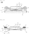
- FIG. 2 is a vertical sectional view showing a cap assembly according to an embodiment of the present invention.
- the cap assembly denoted by reference numeral 210, includes a safety vent 203 configured to rupture in order to exhaust gas when the pressure in a battery case increases, a cap plate 202 mounted on the safety vent 203, and a current interrupt member 204 attached to the lower end of the safety vent 203 for interrupting current when the pressure in the battery case increases.
- a gasket 205 which is configured to have a structure that surrounds the outer circumference of the cap assembly 210 and a portion of the lower surface of the cap assembly 210, is coupled to a washer 211 via a thermoplastic adhesive layer 221.
- the thermoplastic adhesive layer 221 is attached so as to extend from the portion of the washer 211 that is spaced apart inwards from the outer circumference of the washer 211 by a predetermined distance D.
- the outer diameter of the washer 211 is larger than the outer diameter of the gasket 205, and the washer 211 is coupled to the gasket 205 such that the center of the washer 211 is aligned with the center of the gasket 205.
- the gasket 205 is configured to have a structure including a first coupling part 205a, coupled to an outer circumferential portion of the lower surface of the current interrupt member 204, a step part 205b, bent upwards perpendicularly from the outer circumference of the first coupling part 205a, a second coupling part 205c, bent outwards from the upper part of the step part 205b so as to be parallel to the first coupling part and coupled to the lower surface of the safety vent 203, a third coupling part 205d, bent upwards perpendicularly from the outer circumference of the second coupling part 205c and coupled to the outer circumference of the cap plate 202, which surrounds the outer circumference of the safety vent 203, and a fourth coupling part 205e, coupled to the washer 211 so as to serve as the upper outer circumference of the third coupling part 205d.
- the third coupling part 205d may be located so as to be coupled to the outer circumference of the safety vent and to the outer circumference of the cap plate.
- FIG. 3 is a partial vertical sectional view schematically showing the state in which the cap assembly of FIG. 2 is received in a cylindrical battery case
- FIG. 4 is an enlarged view showing part A of FIG. 3 .
- the washer 211 is located on an outer circumferential portion of the open upper surface of the cylindrical battery case 201 in the state of being coupled to the fourth coupling part of the gasket 205 and to a portion of the safety vent 203, which is configured to have a structure that surrounds the cap plate 202, via the thermoplastic adhesive layer 221.
- the washer 211 is located on the outer circumferential portion of the open upper surface of the cylindrical battery case 201 in the state of being coupled to the fourth coupling part of the gasket 205 and to a portion of the cap plate 202, via the thermoplastic adhesive layer 221.
- the outer diameter of the washer 211 is equal to the outer diameter of the battery case 201, and the outer circumference 211a of the lower surface of the washer 211, to which the thermoplastic adhesive layer 221 is not attached, is coupled to the upper surface 201a of the outer circumferential portion of the battery case 201 by welding.
- the battery case 201 has no beading part 120, unlike the battery case 101. Consequently, it is possible to increase the size of the electrode assembly 230 compared to the case in which the beading part is provided. As a result, the distance between the electrode assembly and the current interrupt member, which is located at the lower end of the cap assembly, is reduced so as to be smaller than the height of the step part of the gasket 205.
- the cylindrical battery cell according to the present invention uses a battery case having no beading part and is configured to have a structure in which the cap assembly and the gasket are coupled to the washer via the thermoplastic adhesive layer in order to fix the cap assembly to the battery case. Consequently, it is possible to increase the size of the electrode assembly in proportion to the height of the beading part, which is omitted, whereby it is possible to provide a high-capacity cylindrical battery cell.
- the cylindrical battery cell according to the present invention uses a cylindrical battery case having no beading part and a gasket configured to have a structure that does not surround the upper surface of a cap plate. Consequently, it is possible to increase the size of the cylindrical battery case, in which an electrode assembly is mounted, whereby it is possible to provide a high-capacity cylindrical battery cell.
Landscapes
- Chemical & Material Sciences (AREA)
- Chemical Kinetics & Catalysis (AREA)
- Electrochemistry (AREA)
- General Chemical & Material Sciences (AREA)
- Engineering & Computer Science (AREA)
- Manufacturing & Machinery (AREA)
- Sealing Battery Cases Or Jackets (AREA)
- Gas Exhaust Devices For Batteries (AREA)
- Connection Of Batteries Or Terminals (AREA)
Abstract
Description
- This application claims the benefit of Korean Patent Application No.
2017-0117208 filed on September 13, 2017 - The present invention relates to a cylindrical battery cell having no beading part, and more particularly to a cylindrical battery cell configured to have a structure in which a jelly-roll type electrode assembly is received in a cylindrical battery case having no beading part and in which a gasket, which surrounds the outer circumference of a safety vent and a portion of the lower surface of the safety vent, is coupled to a washer, which fixes a cap assembly, in order to maintain insulation between the cylindrical battery case and the cap assembly, whereby the capacity of the battery cell is increased in proportion to the size of the beading part, which is omitted.
- Secondary batteries, which can be charged and discharged, have been widely used as energy sources for wireless mobile devices. In addition, secondary batteries have attracted considerable attention as energy sources for electric vehicles and hybrid electric vehicles, which have been developed to solve problems, such as air pollution, caused by existing gasoline and diesel vehicles using fossil fuels. Therefore, secondary batteries are being applied in an increasing number of applications owing to the advantages thereof, and, in the future, secondary batteries are expected to be applied to even more applications and products.
- In general, based on the shape of a battery case, secondary batteries are classified into a cylindrical battery having an electrode assembly mounted in a cylindrical metal can, a prismatic battery having an electrode assembly mounted in a prismatic metal can, and a pouch-shaped battery having an electrode assembly mounted in a pouch-shaped case made of an aluminum laminate sheet. The electrode assembly, which is mounted in the battery case, is a power generating element that includes a positive electrode, a negative electrode, and a separator that is interposed between the positive electrode and the negative electrode and that can be charged and discharged. The electrode assembly is classified as a jelly-roll type electrode assembly, which is configured to have a structure in which a long sheet type positive electrode and a long sheet type negative electrode, to which active materials are applied, are wound in the state in which a separator is disposed between the positive electrode and the negative electrode, or a stacked type electrode assembly, which is configured to have a structure in which a plurality of positive electrodes having a predetermined size and a plurality of negative electrodes having a predetermined size are sequentially stacked in the state in which separators are disposed respectively between the positive electrodes and the negative electrodes. The jelly-roll type electrode assembly has advantages in that it is easy to manufacture the jelly-roll type electrode assembly and the jelly-roll type electrode assembly has high energy density per unit weight.
-
FIG. 1 is a vertical sectional view schematically showing the upper part of a general cylindrical battery cell having a beading part. - Referring to
FIG. 1 , a cylindrical battery cell 100 is manufactured by placing a jelly-rolltype electrode assembly 130 in a reception unit defined in acylindrical can 101, injecting an electrolytic solution into the reception unit such that theelectrode assembly 130 is fully impregnated with the electrolytic solution, and coupling acap assembly 110 to the upper end, which is open, of the cylindrical can. - The
cap assembly 110 is connected to apositive electrode tab 131, and is configured to have a structure in which atop cap 102 and asafety vent 103 for lowering internal pressure are disposed in agasket 105 for maintaining airtightness, the gasket being mounted to the upper inner surfaces of a crimping part and abeading part 120 of the cylindrical can, in the state in which thetop cap 102 and thesafety vent 103 are in tight contact with each other. The middle portion of thetop cap 102 protrudes upwards such that thetop cap 102 functions as a positive electrode terminal when thetop cap 102 is connected to an external circuit, and a plurality of through holes, through which gas in the cylindrical can is discharged out of the cylindrical can, is formed along the circumference of the protruding portion of thetop cap 102. - In the case in which the beading part is formed at the cylindrical can, however, the height of the cylindrical can is reduced, whereby the capacity of the battery cell is reduced. Furthermore, in the case in which the height or diameter of the cylindrical can is changed at the time of performing a beading process, it is necessary to change beading conditions. As a result, productivity is reduced, and cost is increased.
- In order to solve these problems, Patent Document 1 discloses a cylindrical battery cell having no beading part. However, the disclosed cylindrical battery cell is configured to have a structure in which a cap assembly is inserted into a cylindrical can by interference fitting and the outer circumference of the cap assembly is welded to the cylindrical can. During assembly of the cap assembly, therefore, the cap assembly or the cylindrical can may be easily damaged.
- Patent Document 2 discloses a cylindrical battery cell having no beading part configured such that a protrusion or a support structure is formed on the inner surface of a cylindrical can in order to fix a cap assembly. However, this patent document does not disclose technology that is capable of increasing the capacity of the battery cell by changing the structure of a gasket for maintaining insulation between the cylindrical can and the cap assembly.
- Therefore, there is an urgent necessity for technology that is capable of coupling a cap assembly to a cylindrical case without damage to the cap assembly while minimizing the size of a dead space defined in the cylindrical can, in which a jelly-roll type electrode assembly is received, in order to increase the capacity of the cylindrical battery cell.
-
- (Patent Document 0001) Korean Patent Application Publication No.
2016-00885858 - (Patent Document 0002) Korean Patent Application Publication No.
2007-0080866 - The present invention has been made in view of the above problems and other technical problems that have yet to be resolved, and it is an object of the present invention to provide a cylindrical battery cell configured to have a structure in which a jelly-roll type electrode assembly is received in a cylindrical battery case having no beading part and in which a gasket for maintaining insulation between a cap assembly and the cylindrical battery case surrounds the outer circumference of a safety vent and a portion of the lower surface of the safety vent, and the gasket is coupled to a washer, which fixes the cap assembly, whereby the size of the cylindrical battery case, in which the jelly-roll type electrode assembly is received, is increased in proportion to the size of the beading part, which is omitted.
- Consequently, it is possible to provide a cylindrical battery cell having a capacity increased in proportion to an increase in the size of an electrode assembly reception unit.
- In accordance with an aspect of the present invention, the above and other objects can be accomplished by the provision of a cylindrical battery cell including a jelly-roll type electrode assembly, configured to have a structure in which a positive electrode and a negative electrode are wound in the state in which a separator is disposed between the positive electrode and the negative electrode, a cylindrical battery case having no beading part, a cap assembly located at the open upper end of the cylindrical battery case, and a gasket mounted so as to surround the outer circumference of a safety vent and a portion of the lower surface of the safety vent in order to maintain insulation between the cap assembly and the cylindrical battery case, wherein the cap assembly includes the safety vent, which is configured to rupture in order to exhaust gas when the pressure in the battery case increases, a cap plate mounted on the safety vent, the cap plate having formed therein through holes for discharging gas, and a current interrupt member attached to the lower end of the safety vent for interrupting current when the pressure in the battery case increases, and wherein the gasket is located on an outer circumferential portion of the open upper surface of the battery case and is coupled to a washer for fixing the cap assembly.
- In general, a cylindrical battery cell is configured such that a top cap, including a current interrupt device (CID), for interrupting current and reducing the magnitude of the pressure in the battery cell when the battery cell operates abnormally, and a positive temperature coefficient (PTC) element, for interrupting current by increasing battery cell resistance when the temperature in the battery cell increases, is coupled to the open upper end of a cylindrical can in order to guarantee the safety of the cylindrical battery cell.
- In order to couple the top cap to the cylindrical can, the upper end portion of the cylindrical can is recessed inwards by a predetermined width, the top cap is loaded on the upper end of the cylindrical can, and the upper end portion of the cylindrical can is bent to form a beading part such that the outer circumference of the top cap is surrounded by the beading part. The coupling of the top cap using the beading part is achieved based on the plastic deformation and high mechanical strength of metal, from which the cylindrical can is made, whereby the coupling of the top cap is stably maintained.
- However, the space in the battery case is reduced due to the formation of the beading part, whereby the capacity of the battery cell is reduced.
- In the case in which the washer, which is located on the open upper surface of the cylindrical battery case, is coupled to the cap assembly, as in the present invention, the cap assembly is fixed in the state in which the washer is attached, whereby the beading part for fixing the cap assembly may be omitted from the battery case.
- Since a battery case having no beading part is used, as described above, it is possible to omit the process of forming the beading part, whereby it is possible to omit the process of adjusting the size of the battery cell in order to form the beading part and thus to reduce cost.
- In addition, since the process of forming the beading part is omitted, it is not necessary to use a gasket configured to have a structure that surrounds a portion of the upper surface of the cap plate. The gasket used in the present invention may be configured to have a structure that surrounds the outer circumference of the cap plate or the outer circumference of the safety vent and a portion of the lower surface of the safety vent.
- In addition, it is possible to increase the height of the jelly-roll type electrode assembly in proportion to the height of the beading part, which is omitted, and therefore it is possible to provide a cylindrical battery cell having a capacity increased in proportion to the increased volume of the electrode assembly.
- In a concrete example, the gasket may be coupled to the washer via a thermoplastic adhesive layer. The thermoplastic adhesive layer is attached to the lower surface of the washer, the gasket is located on the thermoplastic adhesive layer, and the thermoplastic adhesive layer is heated so as to melt, whereby the gasket and the washer may be coupled to each other.
- The thermoplastic adhesive layer is not particularly restricted, as long as the thermoplastic adhesive layer provides high adhesive force without melting at temperatures at which the battery cell is normally used. For example, the thermoplastic adhesive layer may be at least one selected from a group consisting of polyurethane (PU), polyethylene (PE), polypropylene (PP), polyvinyl alcohol (PVA), silicon-based resin, epoxy-based resin, polyester, isocyanate-based resin, and engineering plastic, and the engineering plastic may be polyether ether ketone (PEEK), polyketone (PK), fluoropolymer (FP), liquid crystal polymer (LCP), polyvinylidene fluoride (PVDF), polyphenylene sulfide (PPS), polyphthalamide (PPA), polyamide (PA), polycyclohexylene dimethylene terephthalate (PCT), polybutylene terephthalate (PBT), polyethylene terephthalate (PET), polyoxymethylene (POM), modified polypropylene (PP-modified), ultra high molecular weight polyethylene (PE-UHMW), high-density polyethylene (PE-HD), or low-density polyethylene (PE-LD).
- The cylindrical battery cell according to the present invention does not include a structure for fixing the cap assembly in the cylindrical battery case. The cap assembly may be received in the battery case in the state of being coupled to the washer together with the gasket.
- Since the washer is located on the outer circumferential portion of the open upper surface of the cylindrical battery case in the state of being coupled to the cap assembly, the size of the washer must be set such that the washer cannot move toward the inside of the battery case in the state in which the washer is fixed in position. In the case in which the outer diameter of the washer is larger than the outer diameter of the battery case, however, the size of the upper end of the battery case is unnecessarily increased. Preferably, therefore, the outer diameter of the washer is equal to the outer diameter of the battery case.
- For example, the outer diameter of the cap assembly may be smaller than the outer diameter of the washer, and the cap assembly and the washer may be coupled to each other such that the center of the cap assembly is aligned with the center of the washer. The outer circumference of the washer may extend further outwards than the outer circumference of the cap assembly.
- Consequently, the outer circumference of the lower surface of the washer, which extends further outwards than the outer circumference of the cap assembly, may be coupled to the upper surface of the outer circumferential portion of the battery case by welding in the state of being located so as to be placed on the upper surface of the outer circumferential portion of the battery case.
- In order to increase the force of welding between the battery case and the washer, as described above, the washer may be made of the same material as the battery case.
- The gasket may be configured to have a structure including a first coupling part, coupled to an outer circumferential portion of the lower surface of the current interrupt member, a step part, bent upwards perpendicularly from the outer circumference of the first coupling part, a second coupling part, bent outwards from the upper part of the step part so as to be parallel to the first coupling part and coupled to the lower surface of the safety vent, a third coupling part, bent upwards perpendicularly from the outer circumference of the second coupling part and coupled to an outer circumference of the safety vent and to an outer circumference of the cap plate, and a fourth coupling part, coupled to the washer so as to serve as the upper outer circumference of the third coupling part.
- Consequently, the gasket may be configured to have a structure that surrounds the outer circumference of the safety vent and the outer circumference of the cap plate while supporting a portion of the lower surface of the current interrupt member, located under the cap plate. Alternatively, in the case in which the safety vent is configured to have a structure that surrounds the outer circumference of the cap plate, the gasket may be configured to have a structure that surrounds the outer circumference of the safety vent while supporting a portion of the lower surface of the current interrupt member.
- The washer is coupled to the gasket and to the cap assembly. In order to achieve coupling between the washer and the cap assembly, the washer may have an inner diameter sufficient to cover a portion of the outer circumference of the cap plate.
- Specifically, the gasket and the cap plate may be fixed to the washer in the state in which the washer is coupled to the fourth coupling part of the gasket and to a portion of the cap plate.
- In a concrete example, the distance between the electrode assembly and the lower end of the cap assembly may be smaller than the height of the step part.
- The cylindrical battery cell according to the present invention uses a cylindrical battery case having no beading part. Compared to the case in which the beading part is provided, therefore, the length of the electrode tab coupled to the current interrupt member is reduced, and the height of the electrode assembly is increased in proportion to the height of the beading part, which is omitted. Consequently, the distance between the electrode assembly and the lower end of the cap assembly becomes relatively short.
- In accordance with another aspect of the present invention, there is provided a battery pack including the cylindrical battery cell.
- Specifically, the battery pack may be used as a power source for a device requiring the ability to withstand high temperatures, a long lifespan, high rate characteristics, etc. Specific examples of the device may include a mobile electronic device, a wearable electronic device, a power tool driven by a battery-powered motor, an electric automobile, such as an electric vehicle (EV), a hybrid electric vehicle (HEV), or a plug-in hybrid electric vehicle (PHEV), an electric two-wheeled vehicle, such as an electric bicycle (E-bike) or an electric scooter (E-scooter), an electric golf cart, and an energy storage system. However, the present invention is not limited thereto.
- The structure and manufacturing method of the device are well known in the art to which the present invention pertains, and thus a detailed description thereof will be omitted.
-
-
FIG. 1 is a vertical sectional view showing the upper part of a conventional cylindrical battery cell having a beading part. -
FIG. 2 is a vertical sectional view showing a cap assembly according to an embodiment of the present invention. -
FIG. 3 is a vertical sectional view showing the upper part of a cylindrical battery cell, in which the cap assembly ofFIG. 2 is received. -
FIG. 4 is an enlarged view showing part A ofFIG. 3 . - Now, preferred embodiments of the present invention will be described in detail with reference to the accompanying drawings such that the preferred embodiments of the present invention can be easily implemented by a person having ordinary skill in the art to which the present invention pertains. In describing the principle of operation of the preferred embodiments of the present invention in detail, however, a detailed description of known functions and configurations incorporated herein will be omitted when the same may obscure the subject matter of the present invention.
- Wherever possible, the same reference numbers will be used throughout the drawings to refer to parts that perform similar functions or operations. Meanwhile, in the case in which one part is 'connected' to another part in the following description of the present invention, not only may the one part be directly connected to the another part, but also, the one part may be indirectly connected to the another part via a further part. In addition, that a certain element is 'included' means that other elements are not excluded, but may be further included unless mentioned otherwise.
- Reference will now be made in detail to the preferred embodiments of the present invention, examples of which are illustrated in the accompanying drawings.
-
FIG. 2 is a vertical sectional view showing a cap assembly according to an embodiment of the present invention. - Referring to
FIG. 2 , the cap assembly, denoted byreference numeral 210, includes asafety vent 203 configured to rupture in order to exhaust gas when the pressure in a battery case increases, acap plate 202 mounted on thesafety vent 203, and a current interruptmember 204 attached to the lower end of thesafety vent 203 for interrupting current when the pressure in the battery case increases. - A
gasket 205, which is configured to have a structure that surrounds the outer circumference of thecap assembly 210 and a portion of the lower surface of thecap assembly 210, is coupled to awasher 211 via a thermoplasticadhesive layer 221. The thermoplasticadhesive layer 221 is attached so as to extend from the portion of thewasher 211 that is spaced apart inwards from the outer circumference of thewasher 211 by a predetermined distance D. The outer diameter of thewasher 211 is larger than the outer diameter of thegasket 205, and thewasher 211 is coupled to thegasket 205 such that the center of thewasher 211 is aligned with the center of thegasket 205. - The
gasket 205 is configured to have a structure including afirst coupling part 205a, coupled to an outer circumferential portion of the lower surface of the current interruptmember 204, astep part 205b, bent upwards perpendicularly from the outer circumference of thefirst coupling part 205a, asecond coupling part 205c, bent outwards from the upper part of thestep part 205b so as to be parallel to the first coupling part and coupled to the lower surface of thesafety vent 203, athird coupling part 205d, bent upwards perpendicularly from the outer circumference of thesecond coupling part 205c and coupled to the outer circumference of thecap plate 202, which surrounds the outer circumference of thesafety vent 203, and afourth coupling part 205e, coupled to thewasher 211 so as to serve as the upper outer circumference of thethird coupling part 205d. - Alternatively, in the case in which the safety vent is not configured to have a structure that surrounds the outer circumference of the cap plate, the
third coupling part 205d may be located so as to be coupled to the outer circumference of the safety vent and to the outer circumference of the cap plate. -
FIG. 3 is a partial vertical sectional view schematically showing the state in which the cap assembly ofFIG. 2 is received in a cylindrical battery case, andFIG. 4 is an enlarged view showing part A ofFIG. 3 . - Referring to
FIGS. 3 and 4 , thewasher 211 is located on an outer circumferential portion of the open upper surface of thecylindrical battery case 201 in the state of being coupled to the fourth coupling part of thegasket 205 and to a portion of thesafety vent 203, which is configured to have a structure that surrounds thecap plate 202, via the thermoplasticadhesive layer 221. - Alternatively, in the case in which the
safety vent 203 is not configured to have a structure that surrounds thecap plate 202, unlikeFIG. 3 , thewasher 211 is located on the outer circumferential portion of the open upper surface of thecylindrical battery case 201 in the state of being coupled to the fourth coupling part of thegasket 205 and to a portion of thecap plate 202, via the thermoplasticadhesive layer 221. - The outer diameter of the
washer 211 is equal to the outer diameter of thebattery case 201, and theouter circumference 211a of the lower surface of thewasher 211, to which the thermoplasticadhesive layer 221 is not attached, is coupled to theupper surface 201a of the outer circumferential portion of thebattery case 201 by welding. - The
battery case 201 has nobeading part 120, unlike thebattery case 101. Consequently, it is possible to increase the size of the electrode assembly 230 compared to the case in which the beading part is provided. As a result, the distance between the electrode assembly and the current interrupt member, which is located at the lower end of the cap assembly, is reduced so as to be smaller than the height of the step part of thegasket 205. - As is apparent from the above description, the cylindrical battery cell according to the present invention uses a battery case having no beading part and is configured to have a structure in which the cap assembly and the gasket are coupled to the washer via the thermoplastic adhesive layer in order to fix the cap assembly to the battery case. Consequently, it is possible to increase the size of the electrode assembly in proportion to the height of the beading part, which is omitted, whereby it is possible to provide a high-capacity cylindrical battery cell.
- Those skilled in the art to which the present invention pertains will appreciate that various applications and modifications are possible based on the above description without departing from the scope of the present invention.
-
- 100, 200: Cylindrical battery cells
- 101, 201: Cylindrical battery cases
- 102, 202: Top plates
- 103, 203: Safety vents
- 104, 204: Current interrupt member
- 105, 205: Gaskets
- 205a: First coupling part of gasket
- 205b: Step part of gasket
- 205c: Second coupling part of gasket
- 205d: Third coupling part of gasket
- 205e: Fourth coupling part of gasket
- 110, 210: Cap assemblies
- 130, 230: Electrode assemblies
- 131: Positive electrode tab
- 201a: Upper surface of outer circumferential portion of battery case
- 211: Washer
- 211a: Outer circumference of lower surface of washer
- 221: Thermoplastic adhesive layer
- D: Distance between outer circumference of washer and outer circumference of thermoplastic adhesive layer
- As is apparent from the above description, the cylindrical battery cell according to the present invention uses a cylindrical battery case having no beading part and a gasket configured to have a structure that does not surround the upper surface of a cap plate. Consequently, it is possible to increase the size of the cylindrical battery case, in which an electrode assembly is mounted, whereby it is possible to provide a high-capacity cylindrical battery cell.
- In addition, no process of forming the beading part is required, whereby it is possible to prevent a decrease in productivity and an increase in cost due to the production of the beading part.
Claims (12)
- A cylindrical battery cell comprising:a jelly-roll type electrode assembly, configured to have a structure in which a positive electrode and a negative electrode are wound in a state in which a separator is disposed between the positive electrode and the negative electrode;a cylindrical battery case having no beading part;a cap assembly located at an open upper end of the cylindrical battery case; anda gasket mounted so as to surround an outer circumference of a safety vent and a portion of a lower surface of the safety vent in order to maintain insulation between the cap assembly and the cylindrical battery case, wherein
the cap assembly comprises the safety vent, which is configured to rupture in order to exhaust gas when a pressure in the cylindrical battery case increases, a cap plate mounted on the safety vent, the cap plate having formed therein through holes for discharging gas, and a current interrupt member attached to a lower end of the safety vent for interrupting current when the pressure in the cylindrical battery case increases, and wherein
the gasket is located on an outer circumferential portion of an open upper surface of the cylindrical battery case and is coupled to a washer for fixing the cap assembly. - The cylindrical battery cell according to claim 1, wherein the gasket is coupled to the washer via a thermoplastic adhesive layer.
- The cylindrical battery cell according to claim 2, wherein
the thermoplastic adhesive layer is at least one selected from a group consisting of polyurethane (PU), polyethylene (PE), polypropylene (PP), polyvinyl alcohol (PVA), silicon-based resin, epoxy-based resin, polyester, isocyanate-based resin, and engineering plastic,
the engineering plastic being selected from a group consisting of polyether ether ketone (PEEK), polyketone (PK), fluoropolymer (FP), liquid crystal polymer (LCP), polyvinylidene fluoride (PVDF), polyphenylene sulfide (PPS), polyphthalamide (PPA), polyamide (PA), polycyclohexylene dimethylene terephthalate (PCT), polybutylene terephthalate (PBT), polyethylene terephthalate (PET), polyoxymethylene (POM), modified polypropylene (PP-modified), ultra high molecular weight polyethylene (PE-UHMW), high-density polyethylene (PE-HD),and low-density polyethylene (PE-LD). - The cylindrical battery cell according to claim 1, wherein the cap assembly is received in the cylindrical battery case in a state of being coupled to the washer together with the gasket.
- The cylindrical battery cell according to claim 1, wherein the washer has an outer diameter equal to an outer diameter of the cylindrical battery case.
- The cylindrical battery cell according to claim 1, wherein an outer circumference of a lower surface of the washer is coupled to the upper surface of the outer circumferential portion of the cylindrical battery case by welding.
- The cylindrical battery cell according to claim 1, wherein the washer is made of a same material as the cylindrical battery case.
- The cylindrical battery cell according to claim 1, wherein the gasket is configured to have a structure comprising:a first coupling part, coupled to an outer circumferential portion of a lower surface of the current interrupt member;a step part, bent upwards perpendicularly from an outer circumference of the first coupling part;a second coupling part, bent outwards from an upper part of the step part so as to be parallel to the first coupling part and coupled to a lower surface of the safety vent;a third coupling part, bent upwards perpendicularly from an outer circumference of the second coupling part and coupled to an outer circumference of the safety vent and to an outer circumference of the cap plate; anda fourth coupling part, coupled to the washer so as to serve as an upper outer circumference of the third coupling part.
- The cylindrical battery cell according to claim 1, wherein the washer has an inner diameter sufficient to cover a portion of an outer circumference of the cap plate.
- The cylindrical battery cell according to claim 1, wherein the washer is coupled to the fourth coupling part of the gasket and to a portion of the cap plate.
- The cylindrical battery cell according to claim 1, wherein a distance between the jelly-roll type electrode assembly and a lower end of the cap assembly is smaller than a height of the step part.
- A battery pack comprising the cylindrical battery cell according to any one of claims 1 to 11.
Applications Claiming Priority (2)
| Application Number | Priority Date | Filing Date | Title |
|---|---|---|---|
| KR1020170117208A KR102263435B1 (en) | 2017-09-13 | 2017-09-13 | Cylindrical Battery Cell Having no Beading Part |
| PCT/KR2018/010740 WO2019054765A1 (en) | 2017-09-13 | 2018-09-13 | CYLINDRICAL BATTERY CELL WITHOUT SPHERICAL ELEMENT |
Publications (3)
| Publication Number | Publication Date |
|---|---|
| EP3584853A1 true EP3584853A1 (en) | 2019-12-25 |
| EP3584853A4 EP3584853A4 (en) | 2020-05-06 |
| EP3584853B1 EP3584853B1 (en) | 2023-04-26 |
Family
ID=65722808
Family Applications (1)
| Application Number | Title | Priority Date | Filing Date |
|---|---|---|---|
| EP18857031.1A Active EP3584853B1 (en) | 2017-09-13 | 2018-09-13 | Cylindrical battery cell having no beading part |
Country Status (6)
| Country | Link |
|---|---|
| US (1) | US11063318B2 (en) |
| EP (1) | EP3584853B1 (en) |
| JP (1) | JP6780217B2 (en) |
| KR (1) | KR102263435B1 (en) |
| CN (1) | CN110352511B (en) |
| WO (1) | WO2019054765A1 (en) |
Cited By (4)
| Publication number | Priority date | Publication date | Assignee | Title |
|---|---|---|---|---|
| EP3940810A4 (en) * | 2019-06-18 | 2022-05-04 | LG Energy Solution, Ltd. | CYLINDRICAL SECONDARY BATTERY INCLUDING A GASKET HAVING A GROOVE |
| EP4099496A4 (en) * | 2020-01-31 | 2024-08-07 | Panasonic Intellectual Property Management Co., Ltd. | Power storage device |
| EP4175030A4 (en) * | 2020-12-29 | 2025-01-22 | LG Energy Solution, Ltd. | CYLINDRICAL BATTERY CELL AND BATTERY PACK AND VEHICLE THEREWITH |
| EP4300703A4 (en) * | 2021-02-23 | 2025-03-12 | LG Energy Solution, Ltd. | Secondary battery, secondary battery manufacturing method, battery pack and vehicle |
Families Citing this family (25)
| Publication number | Priority date | Publication date | Assignee | Title |
|---|---|---|---|---|
| EP3780136A4 (en) * | 2018-04-06 | 2021-04-28 | Panasonic Corporation | CELL |
| EP3965196A1 (en) * | 2020-09-07 | 2022-03-09 | VARTA Microbattery GmbH | Energy storage cell |
| US12132227B2 (en) | 2021-01-19 | 2024-10-29 | Lg Energy Solution, Ltd. | Battery, and battery pack and vehicle comprising the same |
| CA3202317A1 (en) | 2021-01-19 | 2022-07-28 | Lg Energy Solution, Ltd. | Battery and current collector applied thereto, and battery pack and vehicle including the same |
| US12407028B2 (en) | 2021-02-19 | 2025-09-02 | Lg Energy Solution, Ltd. | Electrode assembly, battery, and battery pack and vehicle including the same |
| KR102721148B1 (en) * | 2021-05-27 | 2024-10-24 | 삼성에스디아이 주식회사 | Cylindrical secondary battery |
| CN113270669B (en) * | 2021-06-17 | 2024-08-13 | 湖北亿纬动力有限公司 | Electrode cover plate and battery |
| KR102601042B1 (en) | 2021-09-10 | 2023-11-13 | 삼성에스디아이 주식회사 | Cylindrical secondary battery |
| EP4258462A4 (en) | 2021-09-30 | 2024-10-09 | LG Energy Solution, Ltd. | CYLINDRICAL BATTERY CELL, BATTERY PACK AND VEHICLE COMPRISING THE SAME AND METHOD FOR PRODUCING A CYLINDRICAL BATTERY CELL |
| CA3233300A1 (en) | 2021-09-30 | 2023-04-06 | Lg Energy Solution, Ltd. | Electrode assembly, cylindrical battery cell, and battery pack and vehicle comprising the same |
| HUE071772T2 (en) | 2021-10-14 | 2025-09-28 | Lg Energy Solution Ltd | Battery, current collector plate applied thereto, and battery pack and vehicle comprising the same |
| EP4366073A4 (en) | 2021-10-29 | 2025-08-13 | Lg Energy Solution Ltd | CYLINDRICAL BATTERY CELL AND BATTERY PACK THEREOF AS WELL AS VEHICLE THEREOF AND CURRENT COLLECTION PLATE |
| WO2023075520A1 (en) | 2021-10-29 | 2023-05-04 | 주식회사 엘지에너지솔루션 | Cylindrical secondary battery comprising improved current collector plate, and battery pack and vehicle including same |
| US12249681B2 (en) | 2021-11-19 | 2025-03-11 | Lg Energy Solution, Ltd. | Electrode assembly, battery, and battery pack and vehicle including the same |
| KR102578159B1 (en) * | 2022-01-19 | 2023-09-13 | 삼성에스디아이 주식회사 | Cylindrical secondary battery |
| WO2024014939A1 (en) | 2022-07-15 | 2024-01-18 | 주식회사 엘지에너지솔루션 | Cylindrical battery cell, and battery pack and vehicle including same |
| CN119895636A (en) * | 2022-09-30 | 2025-04-25 | 松下知识产权经营株式会社 | Power storage device |
| CA3246327A1 (en) * | 2022-12-23 | 2025-06-13 | Lg Energy Solution, Ltd. | Battery cell, battery pack, and vehicle including same |
| US12542330B2 (en) | 2023-06-30 | 2026-02-03 | Rivian Ip Holdings, Llc | Battery subassembly with potting material |
| US12471245B2 (en) | 2023-06-30 | 2025-11-11 | Rivian Ip Holdings, Llc | Cold plate |
| US12525671B2 (en) | 2023-06-30 | 2026-01-13 | Rivian Ip Holdings, Llc | Battery welds |
| KR20250018036A (en) | 2023-07-28 | 2025-02-04 | 주식회사 엘지에너지솔루션 | Cylindrical battery cell and, battery pack and vehicle including the same and, current collector plate |
| EP4576408A4 (en) | 2023-08-03 | 2026-03-18 | Lg Energy Solution Ltd | Current collector plate, cylindrical battery cell with it and battery pack and vehicle with the cylindrical battery cell |
| KR20250038953A (en) * | 2023-09-13 | 2025-03-20 | 삼성에스디아이 주식회사 | Secondary battery |
| KR20250151840A (en) * | 2024-04-15 | 2025-10-22 | 삼성에스디아이 주식회사 | Cap assembly and secondary battery including the same |
Family Cites Families (41)
| Publication number | Priority date | Publication date | Assignee | Title |
|---|---|---|---|---|
| US3922178A (en) * | 1971-07-30 | 1975-11-25 | Union Carbide Corp | Alkaline battery seal and protective coating comprising a fatty acidamide |
| US4256815A (en) * | 1980-01-21 | 1981-03-17 | Union Carbide Corporation | Seals for electrochemical cells |
| JPH08180849A (en) * | 1994-12-22 | 1996-07-12 | Fuji Elelctrochem Co Ltd | Explosion-proof structure of electrochemical device |
| EP0849815B1 (en) * | 1996-07-09 | 2005-05-04 | Matsushita Electric Industrial Co., Ltd. | Secondary cell with assembly sealing plate |
| JP3363910B2 (en) * | 1997-03-19 | 2003-01-08 | 旭化成株式会社 | Non-aqueous thin battery |
| WO2000036689A1 (en) * | 1998-12-15 | 2000-06-22 | Electric Fuel Limited | Structure for a prism-shaped metal-air battery cell with features to prevent electrolyte leakage and to maintain connectivity between an air cathode and a casing element |
| TW504854B (en) * | 1999-08-27 | 2002-10-01 | Toshiba Battery | Flat non-aqueous electrolyte secondary cell |
| JP4028700B2 (en) | 2001-08-07 | 2007-12-26 | 松下電器産業株式会社 | Alkaline battery |
| US20050112462A1 (en) * | 2003-11-21 | 2005-05-26 | Marple Jack W. | High discharge capacity lithium battery |
| KR100449762B1 (en) * | 2002-09-05 | 2004-09-22 | 삼성에스디아이 주식회사 | Lithium secondary battery |
| JP4567374B2 (en) * | 2003-08-28 | 2010-10-20 | パナソニック株式会社 | Battery and manufacturing method thereof |
| EP1777763A3 (en) * | 2005-10-21 | 2007-12-26 | Matsushita Electric Industrial Co., Ltd. | Alkaline battery |
| KR100855182B1 (en) | 2006-02-09 | 2008-08-28 | 주식회사 엘지화학 | Cylindrical battery with top cap coupled by welding |
| US20100015508A1 (en) | 2006-12-05 | 2010-01-21 | In-Young Hwang | Cylindrical secondary battery and method of manufacturing the same |
| KR101006883B1 (en) * | 2006-12-23 | 2011-01-12 | 주식회사 엘지화학 | Battery containing electrolyte suction washer |
| KR100947989B1 (en) * | 2007-11-06 | 2010-03-18 | 삼성에스디아이 주식회사 | Secondary Battery and Manufacturing Method Thereof |
| US8147999B2 (en) * | 2008-06-11 | 2012-04-03 | Eveready Battery Company, Inc. | Closure assembly with low vapor transmission for electrochemical cell |
| KR20200124769A (en) | 2009-11-20 | 2020-11-03 | 가부시키가이샤 한도오따이 에네루기 켄큐쇼 | Transistor |
| KR101093924B1 (en) * | 2010-01-11 | 2011-12-13 | 삼성에스디아이 주식회사 | Secondary battery |
| WO2011101930A1 (en) * | 2010-02-19 | 2011-08-25 | パナソニック株式会社 | Coin-shaped lithium secondary battery |
| KR101310731B1 (en) * | 2010-03-22 | 2013-09-24 | 주식회사 엘지화학 | Secondary battery |
| KR101293208B1 (en) | 2010-03-22 | 2013-08-05 | 주식회사 엘지화학 | Cap assembly for secondary battery |
| KR101184403B1 (en) * | 2010-10-21 | 2012-09-19 | 주식회사 엘지화학 | Cap assembly and secondary battery using the same |
| KR101511302B1 (en) * | 2010-11-03 | 2015-04-10 | 주식회사 엘지화학 | Secondary battery |
| KR20120052586A (en) * | 2010-11-16 | 2012-05-24 | 주식회사 엘지화학 | Cap assembly and secondary battery using the same |
| KR101142622B1 (en) * | 2010-11-19 | 2012-05-03 | 삼성에스디아이 주식회사 | Battery pack |
| KR101281038B1 (en) * | 2010-12-07 | 2013-07-09 | 주식회사 엘지화학 | Cap assembly and secondary battery using the same |
| KR101254174B1 (en) | 2011-03-08 | 2013-04-18 | 주식회사 엘지화학 | Cylindrical Secondary Battery of Improved Safety |
| JP5767407B2 (en) * | 2011-07-13 | 2015-08-19 | エルジー・ケム・リミテッド | Cylindrical secondary battery |
| KR101326069B1 (en) | 2011-12-26 | 2013-11-07 | 주식회사 엘지화학 | Cap Assembly of Improved Productivity and Cylindrical Battery Cell Employed with the Same |
| JP5935013B2 (en) * | 2012-02-24 | 2016-06-15 | パナソニックIpマネジメント株式会社 | Cylindrical alkaline storage battery |
| EP2690687A1 (en) * | 2012-07-26 | 2014-01-29 | VARTA Microbattery GmbH | Button cell with anode coil and method for its production |
| KR20140106329A (en) | 2013-02-26 | 2014-09-03 | 주식회사 엘지화학 | Cap assembly and secondary battery including the same |
| KR101514827B1 (en) | 2013-02-26 | 2015-04-23 | 주식회사 엘지화학 | Secondary battery and method for manufacturing the same |
| GB2521167A (en) | 2013-12-11 | 2015-06-17 | British American Tobacco Co | An apparatus for forming a circumferential slit in a tobacco industry rod article |
| US10147967B2 (en) * | 2014-07-24 | 2018-12-04 | Panasonic Intellectual Property Management Co., Ltd. | Cylindrical battery |
| KR101889592B1 (en) | 2015-01-16 | 2018-08-17 | 주식회사 엘지화학 | Beading-free Cylindrical Battery and Manufacturing Method for the Same |
| KR101947477B1 (en) * | 2015-07-21 | 2019-02-13 | 주식회사 엘지화학 | Cap Assembly of Improved Safety and Cylindrical Secondary Battery Comprising the Same |
| WO2017037981A1 (en) * | 2015-08-31 | 2017-03-09 | パナソニックIpマネジメント株式会社 | Nonaqueous electrolyte secondary battery |
| KR102112692B1 (en) | 2015-11-30 | 2020-05-19 | 주식회사 엘지화학 | Coin cell |
| KR102093386B1 (en) * | 2016-06-22 | 2020-03-25 | 주식회사 엘지화학 | Secondary battery and method of interrupting current of the secondary battery |
-
2017
- 2017-09-13 KR KR1020170117208A patent/KR102263435B1/en active Active
-
2018
- 2018-09-13 CN CN201880013674.1A patent/CN110352511B/en active Active
- 2018-09-13 US US16/489,602 patent/US11063318B2/en active Active
- 2018-09-13 JP JP2019546849A patent/JP6780217B2/en active Active
- 2018-09-13 WO PCT/KR2018/010740 patent/WO2019054765A1/en not_active Ceased
- 2018-09-13 EP EP18857031.1A patent/EP3584853B1/en active Active
Cited By (5)
| Publication number | Priority date | Publication date | Assignee | Title |
|---|---|---|---|---|
| EP3940810A4 (en) * | 2019-06-18 | 2022-05-04 | LG Energy Solution, Ltd. | CYLINDRICAL SECONDARY BATTERY INCLUDING A GASKET HAVING A GROOVE |
| EP4099496A4 (en) * | 2020-01-31 | 2024-08-07 | Panasonic Intellectual Property Management Co., Ltd. | Power storage device |
| US12548868B2 (en) | 2020-01-31 | 2026-02-10 | Panasonic Intellectual Property Management Co., Ltd. | Power storage device |
| EP4175030A4 (en) * | 2020-12-29 | 2025-01-22 | LG Energy Solution, Ltd. | CYLINDRICAL BATTERY CELL AND BATTERY PACK AND VEHICLE THEREWITH |
| EP4300703A4 (en) * | 2021-02-23 | 2025-03-12 | LG Energy Solution, Ltd. | Secondary battery, secondary battery manufacturing method, battery pack and vehicle |
Also Published As
| Publication number | Publication date |
|---|---|
| JP2020509546A (en) | 2020-03-26 |
| US20190386272A1 (en) | 2019-12-19 |
| CN110352511A (en) | 2019-10-18 |
| JP6780217B2 (en) | 2020-11-04 |
| EP3584853B1 (en) | 2023-04-26 |
| KR20190030016A (en) | 2019-03-21 |
| CN110352511B (en) | 2022-04-19 |
| EP3584853A4 (en) | 2020-05-06 |
| WO2019054765A1 (en) | 2019-03-21 |
| KR102263435B1 (en) | 2021-06-11 |
| US11063318B2 (en) | 2021-07-13 |
Similar Documents
| Publication | Publication Date | Title |
|---|---|---|
| EP3584853B1 (en) | Cylindrical battery cell having no beading part | |
| US11329348B2 (en) | Cylindrical battery cell comprising metal can having groove | |
| US11404752B2 (en) | Cylindrical secondary battery including welding pole | |
| CN106356490B (en) | Rechargeable battery and battery module including rechargeable battery | |
| KR101326069B1 (en) | Cap Assembly of Improved Productivity and Cylindrical Battery Cell Employed with the Same | |
| KR101244735B1 (en) | Rechargeable battery | |
| US20130122355A1 (en) | Rechargeable battery | |
| US20230052005A1 (en) | Electrode assembly including disconnection preventing layer and method for manufacturing the same | |
| US20200203700A1 (en) | Electrode Assembly Including Plastic Member Applied to Electrode Tabs-Lead Coupling Portion and Secondary Battery Including the Same | |
| CN114631222A (en) | Secondary battery and sealing block | |
| US11081759B2 (en) | Secondary battery | |
| JP2025527823A (en) | Battery cell, battery pack and automobile including the same | |
| KR102700494B1 (en) | Battery | |
| KR102563880B1 (en) | Cartridge for increasing cooling effects | |
| KR102448131B1 (en) | A pouch-type secondary battery composed of a laminate sheet having a partially increased thickness | |
| CN115528389A (en) | Battery and method for manufacturing same | |
| US20160308188A1 (en) | Rechargeable battery | |
| US11990628B2 (en) | Secondary battery | |
| US9893346B2 (en) | Rechargeable battery having short-circuit member | |
| JP5918852B2 (en) | Manufacturing method of secondary battery | |
| KR20150049552A (en) | Secondary battery for having uneven tab and method thereof | |
| JP2024011384A (en) | battery | |
| KR20150066159A (en) | Can assay of litium ion battery with high capacity and power | |
| US20240332685A1 (en) | Secondary battery | |
| CN121175866A (en) | Secondary battery, method for manufacturing secondary battery, and battery pack |
Legal Events
| Date | Code | Title | Description |
|---|---|---|---|
| STAA | Information on the status of an ep patent application or granted ep patent |
Free format text: STATUS: THE INTERNATIONAL PUBLICATION HAS BEEN MADE |
|
| PUAI | Public reference made under article 153(3) epc to a published international application that has entered the european phase |
Free format text: ORIGINAL CODE: 0009012 |
|
| STAA | Information on the status of an ep patent application or granted ep patent |
Free format text: STATUS: REQUEST FOR EXAMINATION WAS MADE |
|
| 17P | Request for examination filed |
Effective date: 20190920 |
|
| AK | Designated contracting states |
Kind code of ref document: A1 Designated state(s): AL AT BE BG CH CY CZ DE DK EE ES FI FR GB GR HR HU IE IS IT LI LT LU LV MC MK MT NL NO PL PT RO RS SE SI SK SM TR |
|
| AX | Request for extension of the european patent |
Extension state: BA ME |
|
| A4 | Supplementary search report drawn up and despatched |
Effective date: 20200408 |
|
| RIC1 | Information provided on ipc code assigned before grant |
Ipc: H01M 2/34 20060101ALI20200402BHEP Ipc: H01M 2/08 20060101ALI20200402BHEP Ipc: H01M 2/04 20060101ALI20200402BHEP Ipc: H01M 2/12 20060101ALI20200402BHEP Ipc: H01M 2/02 20060101AFI20200402BHEP |
|
| DAV | Request for validation of the european patent (deleted) | ||
| DAX | Request for extension of the european patent (deleted) | ||
| RAP1 | Party data changed (applicant data changed or rights of an application transferred) |
Owner name: LG ENERGY SOLUTION LTD. |
|
| RAP3 | Party data changed (applicant data changed or rights of an application transferred) |
Owner name: LG ENERGY SOLUTION, LTD. |
|
| REG | Reference to a national code |
Ref country code: DE Ref legal event code: R079 Ref document number: 602018048991 Country of ref document: DE Free format text: PREVIOUS MAIN CLASS: H01M0002040000 Ipc: H01M0050107000 |
|
| GRAP | Despatch of communication of intention to grant a patent |
Free format text: ORIGINAL CODE: EPIDOSNIGR1 |
|
| STAA | Information on the status of an ep patent application or granted ep patent |
Free format text: STATUS: GRANT OF PATENT IS INTENDED |
|
| RIC1 | Information provided on ipc code assigned before grant |
Ipc: H01M 50/578 20210101ALI20221026BHEP Ipc: H01M 50/342 20210101ALI20221026BHEP Ipc: H01M 50/184 20210101ALI20221026BHEP Ipc: H01M 50/169 20210101ALI20221026BHEP Ipc: H01M 50/166 20210101ALI20221026BHEP Ipc: H01M 50/107 20210101AFI20221026BHEP |
|
| INTG | Intention to grant announced |
Effective date: 20221124 |
|
| GRAS | Grant fee paid |
Free format text: ORIGINAL CODE: EPIDOSNIGR3 |
|
| GRAA | (expected) grant |
Free format text: ORIGINAL CODE: 0009210 |
|
| STAA | Information on the status of an ep patent application or granted ep patent |
Free format text: STATUS: THE PATENT HAS BEEN GRANTED |
|
| AK | Designated contracting states |
Kind code of ref document: B1 Designated state(s): AL AT BE BG CH CY CZ DE DK EE ES FI FR GB GR HR HU IE IS IT LI LT LU LV MC MK MT NL NO PL PT RO RS SE SI SK SM TR |
|
| REG | Reference to a national code |
Ref country code: GB Ref legal event code: FG4D |
|
| REG | Reference to a national code |
Ref country code: CH Ref legal event code: EP |
|
| REG | Reference to a national code |
Ref country code: DE Ref legal event code: R096 Ref document number: 602018048991 Country of ref document: DE |
|
| REG | Reference to a national code |
Ref country code: AT Ref legal event code: REF Ref document number: 1563493 Country of ref document: AT Kind code of ref document: T Effective date: 20230515 |
|
| REG | Reference to a national code |
Ref country code: IE Ref legal event code: FG4D |
|
| P01 | Opt-out of the competence of the unified patent court (upc) registered |
Effective date: 20230525 |
|
| REG | Reference to a national code |
Ref country code: LT Ref legal event code: MG9D |
|
| REG | Reference to a national code |
Ref country code: NL Ref legal event code: MP Effective date: 20230426 |
|
| REG | Reference to a national code |
Ref country code: AT Ref legal event code: MK05 Ref document number: 1563493 Country of ref document: AT Kind code of ref document: T Effective date: 20230426 |
|
| PG25 | Lapsed in a contracting state [announced via postgrant information from national office to epo] |
Ref country code: NL Free format text: LAPSE BECAUSE OF FAILURE TO SUBMIT A TRANSLATION OF THE DESCRIPTION OR TO PAY THE FEE WITHIN THE PRESCRIBED TIME-LIMIT Effective date: 20230426 |
|
| PG25 | Lapsed in a contracting state [announced via postgrant information from national office to epo] |
Ref country code: SE Free format text: LAPSE BECAUSE OF FAILURE TO SUBMIT A TRANSLATION OF THE DESCRIPTION OR TO PAY THE FEE WITHIN THE PRESCRIBED TIME-LIMIT Effective date: 20230426 Ref country code: PT Free format text: LAPSE BECAUSE OF FAILURE TO SUBMIT A TRANSLATION OF THE DESCRIPTION OR TO PAY THE FEE WITHIN THE PRESCRIBED TIME-LIMIT Effective date: 20230828 Ref country code: NO Free format text: LAPSE BECAUSE OF FAILURE TO SUBMIT A TRANSLATION OF THE DESCRIPTION OR TO PAY THE FEE WITHIN THE PRESCRIBED TIME-LIMIT Effective date: 20230726 Ref country code: ES Free format text: LAPSE BECAUSE OF FAILURE TO SUBMIT A TRANSLATION OF THE DESCRIPTION OR TO PAY THE FEE WITHIN THE PRESCRIBED TIME-LIMIT Effective date: 20230426 Ref country code: AT Free format text: LAPSE BECAUSE OF FAILURE TO SUBMIT A TRANSLATION OF THE DESCRIPTION OR TO PAY THE FEE WITHIN THE PRESCRIBED TIME-LIMIT Effective date: 20230426 |
|
| PG25 | Lapsed in a contracting state [announced via postgrant information from national office to epo] |
Ref country code: RS Free format text: LAPSE BECAUSE OF FAILURE TO SUBMIT A TRANSLATION OF THE DESCRIPTION OR TO PAY THE FEE WITHIN THE PRESCRIBED TIME-LIMIT Effective date: 20230426 Ref country code: PL Free format text: LAPSE BECAUSE OF FAILURE TO SUBMIT A TRANSLATION OF THE DESCRIPTION OR TO PAY THE FEE WITHIN THE PRESCRIBED TIME-LIMIT Effective date: 20230426 Ref country code: LV Free format text: LAPSE BECAUSE OF FAILURE TO SUBMIT A TRANSLATION OF THE DESCRIPTION OR TO PAY THE FEE WITHIN THE PRESCRIBED TIME-LIMIT Effective date: 20230426 Ref country code: LT Free format text: LAPSE BECAUSE OF FAILURE TO SUBMIT A TRANSLATION OF THE DESCRIPTION OR TO PAY THE FEE WITHIN THE PRESCRIBED TIME-LIMIT Effective date: 20230426 Ref country code: IS Free format text: LAPSE BECAUSE OF FAILURE TO SUBMIT A TRANSLATION OF THE DESCRIPTION OR TO PAY THE FEE WITHIN THE PRESCRIBED TIME-LIMIT Effective date: 20230826 Ref country code: HR Free format text: LAPSE BECAUSE OF FAILURE TO SUBMIT A TRANSLATION OF THE DESCRIPTION OR TO PAY THE FEE WITHIN THE PRESCRIBED TIME-LIMIT Effective date: 20230426 Ref country code: GR Free format text: LAPSE BECAUSE OF FAILURE TO SUBMIT A TRANSLATION OF THE DESCRIPTION OR TO PAY THE FEE WITHIN THE PRESCRIBED TIME-LIMIT Effective date: 20230727 |
|
| PG25 | Lapsed in a contracting state [announced via postgrant information from national office to epo] |
Ref country code: FI Free format text: LAPSE BECAUSE OF FAILURE TO SUBMIT A TRANSLATION OF THE DESCRIPTION OR TO PAY THE FEE WITHIN THE PRESCRIBED TIME-LIMIT Effective date: 20230426 |
|
| PG25 | Lapsed in a contracting state [announced via postgrant information from national office to epo] |
Ref country code: SK Free format text: LAPSE BECAUSE OF FAILURE TO SUBMIT A TRANSLATION OF THE DESCRIPTION OR TO PAY THE FEE WITHIN THE PRESCRIBED TIME-LIMIT Effective date: 20230426 |
|
| REG | Reference to a national code |
Ref country code: DE Ref legal event code: R097 Ref document number: 602018048991 Country of ref document: DE |
|
| PG25 | Lapsed in a contracting state [announced via postgrant information from national office to epo] |
Ref country code: SM Free format text: LAPSE BECAUSE OF FAILURE TO SUBMIT A TRANSLATION OF THE DESCRIPTION OR TO PAY THE FEE WITHIN THE PRESCRIBED TIME-LIMIT Effective date: 20230426 Ref country code: SK Free format text: LAPSE BECAUSE OF FAILURE TO SUBMIT A TRANSLATION OF THE DESCRIPTION OR TO PAY THE FEE WITHIN THE PRESCRIBED TIME-LIMIT Effective date: 20230426 Ref country code: RO Free format text: LAPSE BECAUSE OF FAILURE TO SUBMIT A TRANSLATION OF THE DESCRIPTION OR TO PAY THE FEE WITHIN THE PRESCRIBED TIME-LIMIT Effective date: 20230426 Ref country code: EE Free format text: LAPSE BECAUSE OF FAILURE TO SUBMIT A TRANSLATION OF THE DESCRIPTION OR TO PAY THE FEE WITHIN THE PRESCRIBED TIME-LIMIT Effective date: 20230426 Ref country code: DK Free format text: LAPSE BECAUSE OF FAILURE TO SUBMIT A TRANSLATION OF THE DESCRIPTION OR TO PAY THE FEE WITHIN THE PRESCRIBED TIME-LIMIT Effective date: 20230426 Ref country code: CZ Free format text: LAPSE BECAUSE OF FAILURE TO SUBMIT A TRANSLATION OF THE DESCRIPTION OR TO PAY THE FEE WITHIN THE PRESCRIBED TIME-LIMIT Effective date: 20230426 |
|
| PLBE | No opposition filed within time limit |
Free format text: ORIGINAL CODE: 0009261 |
|
| STAA | Information on the status of an ep patent application or granted ep patent |
Free format text: STATUS: NO OPPOSITION FILED WITHIN TIME LIMIT |
|
| 26N | No opposition filed |
Effective date: 20240129 |
|
| REG | Reference to a national code |
Ref country code: CH Ref legal event code: PL |
|
| PG25 | Lapsed in a contracting state [announced via postgrant information from national office to epo] |
Ref country code: SI Free format text: LAPSE BECAUSE OF FAILURE TO SUBMIT A TRANSLATION OF THE DESCRIPTION OR TO PAY THE FEE WITHIN THE PRESCRIBED TIME-LIMIT Effective date: 20230426 |
|
| PG25 | Lapsed in a contracting state [announced via postgrant information from national office to epo] |
Ref country code: LU Free format text: LAPSE BECAUSE OF NON-PAYMENT OF DUE FEES Effective date: 20230913 |
|
| REG | Reference to a national code |
Ref country code: BE Ref legal event code: MM Effective date: 20230930 |
|
| PG25 | Lapsed in a contracting state [announced via postgrant information from national office to epo] |
Ref country code: SI Free format text: LAPSE BECAUSE OF FAILURE TO SUBMIT A TRANSLATION OF THE DESCRIPTION OR TO PAY THE FEE WITHIN THE PRESCRIBED TIME-LIMIT Effective date: 20230426 Ref country code: LU Free format text: LAPSE BECAUSE OF NON-PAYMENT OF DUE FEES Effective date: 20230913 Ref country code: IT Free format text: LAPSE BECAUSE OF FAILURE TO SUBMIT A TRANSLATION OF THE DESCRIPTION OR TO PAY THE FEE WITHIN THE PRESCRIBED TIME-LIMIT Effective date: 20230426 Ref country code: MC Free format text: LAPSE BECAUSE OF FAILURE TO SUBMIT A TRANSLATION OF THE DESCRIPTION OR TO PAY THE FEE WITHIN THE PRESCRIBED TIME-LIMIT Effective date: 20230426 |
|
| REG | Reference to a national code |
Ref country code: IE Ref legal event code: MM4A |
|
| PG25 | Lapsed in a contracting state [announced via postgrant information from national office to epo] |
Ref country code: IE Free format text: LAPSE BECAUSE OF NON-PAYMENT OF DUE FEES Effective date: 20230913 |
|
| PG25 | Lapsed in a contracting state [announced via postgrant information from national office to epo] |
Ref country code: CH Free format text: LAPSE BECAUSE OF NON-PAYMENT OF DUE FEES Effective date: 20230930 |
|
| PG25 | Lapsed in a contracting state [announced via postgrant information from national office to epo] |
Ref country code: IE Free format text: LAPSE BECAUSE OF NON-PAYMENT OF DUE FEES Effective date: 20230913 Ref country code: CH Free format text: LAPSE BECAUSE OF NON-PAYMENT OF DUE FEES Effective date: 20230930 |
|
| PG25 | Lapsed in a contracting state [announced via postgrant information from national office to epo] |
Ref country code: BE Free format text: LAPSE BECAUSE OF NON-PAYMENT OF DUE FEES Effective date: 20230930 |
|
| PG25 | Lapsed in a contracting state [announced via postgrant information from national office to epo] |
Ref country code: BG Free format text: LAPSE BECAUSE OF FAILURE TO SUBMIT A TRANSLATION OF THE DESCRIPTION OR TO PAY THE FEE WITHIN THE PRESCRIBED TIME-LIMIT Effective date: 20230426 |
|
| PG25 | Lapsed in a contracting state [announced via postgrant information from national office to epo] |
Ref country code: BG Free format text: LAPSE BECAUSE OF FAILURE TO SUBMIT A TRANSLATION OF THE DESCRIPTION OR TO PAY THE FEE WITHIN THE PRESCRIBED TIME-LIMIT Effective date: 20230426 |
|
| PG25 | Lapsed in a contracting state [announced via postgrant information from national office to epo] |
Ref country code: CY Free format text: LAPSE BECAUSE OF FAILURE TO SUBMIT A TRANSLATION OF THE DESCRIPTION OR TO PAY THE FEE WITHIN THE PRESCRIBED TIME-LIMIT; INVALID AB INITIO Effective date: 20180913 |
|
| PG25 | Lapsed in a contracting state [announced via postgrant information from national office to epo] |
Ref country code: HU Free format text: LAPSE BECAUSE OF FAILURE TO SUBMIT A TRANSLATION OF THE DESCRIPTION OR TO PAY THE FEE WITHIN THE PRESCRIBED TIME-LIMIT; INVALID AB INITIO Effective date: 20180913 |
|
| PGFP | Annual fee paid to national office [announced via postgrant information from national office to epo] |
Ref country code: DE Payment date: 20250820 Year of fee payment: 8 |
|
| PGFP | Annual fee paid to national office [announced via postgrant information from national office to epo] |
Ref country code: GB Payment date: 20250820 Year of fee payment: 8 |
|
| PGFP | Annual fee paid to national office [announced via postgrant information from national office to epo] |
Ref country code: FR Payment date: 20250821 Year of fee payment: 8 |
|
| PG25 | Lapsed in a contracting state [announced via postgrant information from national office to epo] |
Ref country code: TR Free format text: LAPSE BECAUSE OF FAILURE TO SUBMIT A TRANSLATION OF THE DESCRIPTION OR TO PAY THE FEE WITHIN THE PRESCRIBED TIME-LIMIT Effective date: 20230426 |