EP3584809A1 - Magnetic unit and an associated method thereof - Google Patents
Magnetic unit and an associated method thereof Download PDFInfo
- Publication number
- EP3584809A1 EP3584809A1 EP19179223.3A EP19179223A EP3584809A1 EP 3584809 A1 EP3584809 A1 EP 3584809A1 EP 19179223 A EP19179223 A EP 19179223A EP 3584809 A1 EP3584809 A1 EP 3584809A1
- Authority
- EP
- European Patent Office
- Prior art keywords
- limb
- magnetic unit
- conductive element
- magnetic
- windings
- Prior art date
- Legal status (The legal status is an assumption and is not a legal conclusion. Google has not performed a legal analysis and makes no representation as to the accuracy of the status listed.)
- Pending
Links
- 238000000034 method Methods 0.000 title abstract description 13
- 238000004804 winding Methods 0.000 claims abstract description 163
- 230000004907 flux Effects 0.000 claims abstract description 90
- 238000012546 transfer Methods 0.000 claims abstract description 17
- 238000006243 chemical reaction Methods 0.000 abstract description 16
- 230000017525 heat dissipation Effects 0.000 description 27
- RYGMFSIKBFXOCR-UHFFFAOYSA-N Copper Chemical compound [Cu] RYGMFSIKBFXOCR-UHFFFAOYSA-N 0.000 description 24
- 229910052802 copper Inorganic materials 0.000 description 21
- 239000010949 copper Substances 0.000 description 21
- 239000000463 material Substances 0.000 description 9
- 239000004593 Epoxy Substances 0.000 description 7
- 150000001875 compounds Chemical class 0.000 description 7
- 239000004519 grease Substances 0.000 description 7
- 238000004382 potting Methods 0.000 description 7
- 239000002826 coolant Substances 0.000 description 6
- 229910052782 aluminium Inorganic materials 0.000 description 4
- XAGFODPZIPBFFR-UHFFFAOYSA-N aluminium Chemical compound [Al] XAGFODPZIPBFFR-UHFFFAOYSA-N 0.000 description 4
- 230000008878 coupling Effects 0.000 description 3
- 238000010168 coupling process Methods 0.000 description 3
- 238000005859 coupling reaction Methods 0.000 description 3
- CSCPPACGZOOCGX-UHFFFAOYSA-N Acetone Chemical compound CC(C)=O CSCPPACGZOOCGX-UHFFFAOYSA-N 0.000 description 2
- 238000005219 brazing Methods 0.000 description 2
- 230000008859 change Effects 0.000 description 2
- 238000010586 diagram Methods 0.000 description 2
- 230000002708 enhancing effect Effects 0.000 description 2
- 239000012530 fluid Substances 0.000 description 2
- 230000005484 gravity Effects 0.000 description 2
- 238000010438 heat treatment Methods 0.000 description 2
- 230000001939 inductive effect Effects 0.000 description 2
- 239000007788 liquid Substances 0.000 description 2
- 230000003137 locomotive effect Effects 0.000 description 2
- 239000000696 magnetic material Substances 0.000 description 2
- 230000035699 permeability Effects 0.000 description 2
- 239000007787 solid Substances 0.000 description 2
- XLYOFNOQVPJJNP-UHFFFAOYSA-N water Substances O XLYOFNOQVPJJNP-UHFFFAOYSA-N 0.000 description 2
- 239000000853 adhesive Substances 0.000 description 1
- 230000001070 adhesive effect Effects 0.000 description 1
- 230000033228 biological regulation Effects 0.000 description 1
- 239000004020 conductor Substances 0.000 description 1
- 238000013461 design Methods 0.000 description 1
- 238000009413 insulation Methods 0.000 description 1
- 238000004519 manufacturing process Methods 0.000 description 1
- 229910052751 metal Inorganic materials 0.000 description 1
- 239000002184 metal Substances 0.000 description 1
- 238000012986 modification Methods 0.000 description 1
- 230000004048 modification Effects 0.000 description 1
- 238000010248 power generation Methods 0.000 description 1
- 238000012545 processing Methods 0.000 description 1
- 230000005855 radiation Effects 0.000 description 1
- 230000009467 reduction Effects 0.000 description 1
- 238000005245 sintering Methods 0.000 description 1
- 238000003466 welding Methods 0.000 description 1
- 229910000859 α-Fe Inorganic materials 0.000 description 1
Images




Classifications
-
- H—ELECTRICITY
- H01—ELECTRIC ELEMENTS
- H01F—MAGNETS; INDUCTANCES; TRANSFORMERS; SELECTION OF MATERIALS FOR THEIR MAGNETIC PROPERTIES
- H01F3/00—Cores, Yokes, or armatures
- H01F3/10—Composite arrangements of magnetic circuits
- H01F3/14—Constrictions; Gaps, e.g. air-gaps
-
- H—ELECTRICITY
- H01—ELECTRIC ELEMENTS
- H01F—MAGNETS; INDUCTANCES; TRANSFORMERS; SELECTION OF MATERIALS FOR THEIR MAGNETIC PROPERTIES
- H01F27/00—Details of transformers or inductances, in general
- H01F27/34—Special means for preventing or reducing unwanted electric or magnetic effects, e.g. no-load losses, reactive currents, harmonics, oscillations, leakage fields
-
- H—ELECTRICITY
- H01—ELECTRIC ELEMENTS
- H01F—MAGNETS; INDUCTANCES; TRANSFORMERS; SELECTION OF MATERIALS FOR THEIR MAGNETIC PROPERTIES
- H01F27/00—Details of transformers or inductances, in general
- H01F27/08—Cooling; Ventilating
-
- H—ELECTRICITY
- H01—ELECTRIC ELEMENTS
- H01F—MAGNETS; INDUCTANCES; TRANSFORMERS; SELECTION OF MATERIALS FOR THEIR MAGNETIC PROPERTIES
- H01F27/00—Details of transformers or inductances, in general
- H01F27/08—Cooling; Ventilating
- H01F27/22—Cooling by heat conduction through solid or powdered fillings
-
- H—ELECTRICITY
- H01—ELECTRIC ELEMENTS
- H01F—MAGNETS; INDUCTANCES; TRANSFORMERS; SELECTION OF MATERIALS FOR THEIR MAGNETIC PROPERTIES
- H01F27/00—Details of transformers or inductances, in general
- H01F27/24—Magnetic cores
-
- H—ELECTRICITY
- H01—ELECTRIC ELEMENTS
- H01F—MAGNETS; INDUCTANCES; TRANSFORMERS; SELECTION OF MATERIALS FOR THEIR MAGNETIC PROPERTIES
- H01F27/00—Details of transformers or inductances, in general
- H01F27/28—Coils; Windings; Conductive connections
-
- H—ELECTRICITY
- H01—ELECTRIC ELEMENTS
- H01F—MAGNETS; INDUCTANCES; TRANSFORMERS; SELECTION OF MATERIALS FOR THEIR MAGNETIC PROPERTIES
- H01F27/00—Details of transformers or inductances, in general
- H01F27/34—Special means for preventing or reducing unwanted electric or magnetic effects, e.g. no-load losses, reactive currents, harmonics, oscillations, leakage fields
- H01F27/346—Preventing or reducing leakage fields
Definitions
- This disclosure generally relates to a magnetic unit for power conversion, which includes a gapped core for reducing the local fringing flux to provide for more efficient operation.
- Embodiments of the present specification generally relate to a magnetic unit and method of operation of the magnetic unit, and more particularly, to a gapped magnetic unit having reduced winding losses for high frequency power conversion applications.
- power conversion applications such as, motor drives, backup electrical power supplies, and the like use magnetic units, such as inductors/transformers and pulse width modulated (PWM) inverters/converters.
- the PWM inverters/converters typically generate high frequency switching signals.
- gapped magnetic units are employed instead of solid core magnetic units.
- the gapped magnetic unit includes a magnetic core having an air gap and copper wire windings wound on the magnetic core.
- the gapped magnetic units are prone to fringing flux at air gaps.
- the fringing flux at the air gap induces eddy currents in the copper wire windings. Accordingly, the copper wire windings are subjected to higher thermal losses.
- the litz wire reduces copper losses caused due to fringing flux.
- the litz wire has many insulation layers, which increases physical size of the wire itself. As a result, footprint of the magnetic core increases in order to accommodate the litz wire windings.
- a magnetic unit in accordance with one aspect of the present specification, includes a magnetic core.
- the magnetic core includes a first limb and a second limb disposed proximate to the first limb, where a gap is formed between the first limb and the second limb.
- the magnetic unit further includes a first winding wound on the first limb.
- the magnetic unit includes a conductive element disposed facing an outer periphery of the first winding, where the conductive element is configured to control a fringing flux generated at the gap.
- the magnetic unit includes a heat sink operatively coupled to the conductive element, wherein the conductive element is further configured to transfer heat from at least one of the conductive element and the first winding to the heat sink.
- a high frequency power conversion system includes a converter. Further, the high frequency power conversion system includes a magnetic unit operatively coupled to the converter, where the magnetic unit includes a magnetic core.
- the magnetic core includes a first limb and a second limb disposed proximate to the first limb, where a gap is formed between the first limb and the second limb.
- the magnetic unit includes a first winding wound on the first limb.
- the magnetic unit includes a conductive element disposed facing an outer periphery of the first winding, where the conductive element is configured to control a fringing flux generated at the gap.
- the magnetic unit includes a heat sink operatively coupled to the conductive element, wherein the conductive element is further configured to transfer heat from at least one of the conductive element and the first winding to the heat sink.
- a method of operation of a magnetic unit includes generating a fringing flux at a gap formed between a first limb and a second limb.
- the method further includes inducing a current in a conductive element disposed facing an outer periphery of the first winding, based on the fringing flux.
- the method includes generating a cancelation flux at the gap based on the current in the conductive element to control the fringing flux.
- the method includes transferring heat from at least one of the conductive element and the first winding to a heat sink.
- circuit and circuitry and “controller” may include either a single component or a plurality of components, which are either active and/or passive and are connected or otherwise coupled together to provide the described function.
- a magnetic unit As will be described in detail hereinafter, various embodiments of a magnetic unit, a power conversion system employing the magnetic unit, and a method for operation of the magnetic unit are disclosed.
- the exemplary magnetic unit may be employed in high frequency power conversion applications, such as locomotives, aircrafts, renewable power generation systems, hybrid electrical vehicles, and the like.
- the magnetic unit may be an inductor or a transformer.
- the exemplary magnetic unit includes a magnetic core, a plurality of windings, and a conductive element.
- the magnetic core may be a gapped magnetic core or a solid magnetic core.
- the gapped magnetic core may have one or more gaps.
- the gaps of the gapped magnetic core may also be referred to as air gaps.
- the term 'air gap,' as used herein, refers to a non-magnetic region of the magnetic core.
- Use of the gapped magnetic core results in generation of a fringing flux in the gaps during operation of the magnetic unit. Further, a fringing flux may be generated between windings wound on limbs of the magnetic core, where the limbs are separated from each other by a gap.
- limbs are placed a determined distance apart from each other.
- 'fringing flux refers to a phenomenon in which a magnetic flux flowing in a magnetic core, spreads out (or fringes out) into a surrounding medium, for example, in and around the gap.
- the magnetic unit includes a conductive element.
- the conductive element is electrically and thermally conductive.
- the electrically conductive element allows flow of an electrical current in one or more directions.
- the thermally conductive element allows transfer of heat.
- the use of the conductive element aids in reducing copper losses due to fringing flux generated at the air gap of the magnetic core. Further, use of the conductive element aids in reducing copper losses due to the fringing flux generated between the windings wound on limbs of the magnetic core. Furthermore, use of the conductive element aids in transfer of heat to a heat sink thus providing an enhanced thermal management.
- the exemplary magnetic unit provides a low-cost and compact solution for reduction of copper losses due to the fringing flux.
- the term 'copper losses,' as used herein, refers to heat produced by electrical current flowing in windings of transformers or other electrical devices/elements.
- FIG. 1 is a perspective view of a magnetic unit 100 according to aspects of the present specification.
- the magnetic unit 100 is a three-phase magnetic unit.
- the magnetic unit 100 includes a magnetic core 101.
- the magnetic core 101 includes a first magnetic leg 102A, a second magnetic leg 102B, and a third magnetic leg 102C.
- Each of the magnetic legs 102A, 102B, and 102C includes a first limb (not shown in FIG. 1 ) and a second limb (not shown in FIG. 1 ).
- a first winding 104A is wound on the first limb of each of the magnetic legs 102A, 102B, and 102C.
- a second winding 104B is wound on the second limb of each of the magnetic legs 102A, 102B, and 102C.
- the first winding 104A may be a primary winding and the second winding 104B may be a secondary winding or vice versa.
- the first and second windings 104A, 104B are split windings, since the first and second windings 104A, 104B are not coupled to each other and are wound on two different limbs of each of the magnetic legs 102A, 102B, 102C. Further, the first and second windings 104A, 104B are separated from each other.
- first and second windings 104A, 104B are copper wires. In one embodiment, the first and second windings 104A, 104B have a rectangular cross-section. In another embodiment, the first and second windings 104A, 104B may have a circular cross-section, a square cross-section, and the like.
- a gap is formed between the first and second limbs of each of the magnetic legs 102A, 102B, and 102C.
- the gap formed between the first and second limbs of each of the magnetic legs 102A, 102B, and 102C is referred to as an air gap.
- the air gaps corresponding to the magnetic legs 102A, 102B, and 102C are represented by reference numerals 106A, 106B, and 106C respectively.
- a fringing flux is generated at the air gap.
- windings are disposed facing or proximate to the air gaps.
- the fringing flux tends to induce high magnitude eddy current in the windings.
- the high magnitude of the eddy current results in higher copper losses in the windings.
- the term 'eddy current,' as used herein, refers to a localized electrical current induced in a conductor by a varying magnetic field.
- the first and second windings 104A, 104B are disposed at a determined distance from the corresponding air gaps 106A, 106B, 106C. In one embodiment, the determined distance may be about 4 mm to 5 mm. Additionally, the conductive elements 108A, 108B, 108C, and 108D are disposed facing an outer periphery (not shown in FIG. 1 ) of at least one of the first and second windings 104A, 104B. The conductive elements 108A, 108B, 108C, 108D are not disposed between an inner periphery (not shown in FIG. 1 ) of at least one the first and second windings 104A, 104B and the corresponding magnetic legs 102A, 102B, 102C.
- the conductive elements 108A, 108B, 108C, and 108D are disposed facing the air gaps 106A, 106B, and 106C. In one specific embodiment, the conductive elements 108A, 108B, 108C, and 108 D are disposed at a distance of about 1 millimeter (mm) from the corresponding air gaps 106A, 106B, and 106C. The distance of the conductive elements 108A, 108B, 108C, and 108D from the corresponding air gaps 106A, 106B, and 106C is determined based on a rating of the magnetic unit 100.
- the conductive elements 108A, 108B, 108C, 108D are made of a non-magnetic material having a low permeability.
- the conductive elements 108A, 108B, 108C, 108D may be made of aluminum, copper, and the like.
- the conductive elements 108A, 108B, 108C, 108D may be in the form of a sheet or a wire loop.
- the conductive elements 108A, 108B, 108C, 108D may have a non-uniform dimension.
- the conductive elements 108A, 108B, 108C, 108D include slots.
- a fringing flux is generated at the air gaps 106A, 106B, and 106C during operation of the magnetic unit 100. Further, in one embodiment, a fringing flux may be generated between the first windings 104A and/or the second windings 104B of the magnetic legs 102A, 102B, and 102C. As noted hereinabove, the first and second windings 104A, 104B are disposed at a predetermined distance away from each of the corresponding air gaps 106A, 106B, 106C. Hence, magnitude of the eddy current induced at the first and second windings 104A, 104B is lower compared to the conventional gapped magnetic unit where windings are disposed proximate to air gaps. Accordingly, the heat generated at the first and second windings 104A, 104B is relatively lower.
- the magnetic unit 100 includes the conductive elements 108A, 108B, 108C, 108D.
- the fringing flux generated at the air gaps 106A, 106B, and 106C induces eddy currents at the conductive elements 108A, 108B, 108C, 108D.
- the fringing flux generated between the first windings 104A and/or the second windings 104B induces eddy currents at the conductive elements 108A, 108B, 108C, 108D.
- the eddy currents induced at the conductive elements 108A, 108B, 108C, 108D results in heating of the conductive elements 108A, 108B, 108C, 108D.
- a cancelation flux is generated at the corresponding air gaps 106A, 106B, 106C, respectively, according to Lenz's law.
- Lenz's law states that a current induced in a circuit due to a change in a magnetic field is directed to oppose the change in flux.
- the cancelation flux has a reverse polarity compared to a polarity of the fringing flux.
- the fringing flux is controlled.
- the magnitude of the eddy currents induced at least in the first and second windings 104A, 104B are reduced.
- the heat generated at the first and second windings 104A, 104B is reduced.
- the magnetic unit 100 further includes a heat sink 110.
- a combination of the heat sink 110 and the conductive elements 108A, 108B, 108C, and 108D may be referred to as a thermal management device.
- the conductive elements 108A, 108B, 108C, 108D function as fins of the heat sink 110.
- the term 'heat sink,' as used herein, refers to a heat exchanger that transfers heat generated by an electronic, an electrical, or a mechanical device to a fluid medium, such as air or a liquid coolant, where heat is dissipated away from the device, thereby allowing regulation of the temperature of the device.
- the heat sink 110 includes heat pipes (not shown in FIG. 1 ) and a heat dissipation base 112.
- the conductive elements 108A, 108B, 108C, 108D are operatively coupled to the heat sink 110 and specifically, to the heat dissipation base 112.
- the conductive elements 108A, 108B, 108C, 108D are used to transfer the generated heat to the heat sink 110.
- the heat generated at the first and second windings 104A, 104B is transferred to the conductive elements 108A, 108B, 108C, 108D via thermal interface material including grease, epoxy, pad, other potting compounds, air, and the like.
- heat generated at the first and second windings 104A, 104B is also transferred by convection and/or radiation to the conductive elements 108A, 108B, 108C, 108D.
- the conductive elements 108A, 108B, 108C, 108D transfers the heat to the heat sink 110 by conduction. Therefore, the conductive elements 108A, 108B, 108C, 108D contribute towards dissipation of heat in addition to reducing copper losses in the windings 104A, 104B due to the fringing flux generated at the air gaps 106A, 106B, and 106C.
- the temperature of the magnetic units is maintained at an optimal value.
- FIG. 1 depicts a three-phase magnetic unit
- use of a single phase magnetic unit having a magnetic core having a single magnetic leg is also envisioned.
- use of multi-phase magnetic units is envisioned.
- FIG. 1 depicts densely packed windings on each limb of a magnetic leg, use of sparsely packed windings on each limb of the magnetic leg is envisaged.
- magnetic core includes three first limbs and three second limbs, in other embodiments, the number of limbs may vary. In one embodiment, a magnetic core may include three first limbs and one second limb.
- FIG. 2 a cross-sectional representation of a portion of a magnetic unit 100, according to aspects of the present specification is shown.
- FIG. 2 is a cross-sectional view along the line 2-2 of FIG. 1 .
- FIG. 2 represents specifically a cross-section of a single magnetic leg 102A of the magnetic unit 100.
- the magnetic leg 102A includes a first limb 202A and a second limb 204A.
- the first limb 202A is disposed proximate to the second limb 204A such that the air gap 106A is formed between the first and second limbs 202A, 204A.
- the first limb 202A is aligned with the second limb 204A.
- first limb 202A aligned with the second limb 204A' refers to alignment of a central axis of the first limb 202A with a central axis of the second limb 204A.
- the term 'central axis of the first limb 202A' refers to an axis passing through a center of gravity of the first limb 202A along a y-axis direction.
- the term 'central axis of the second limb 204A' refers to an axis passing through a center of gravity of the second limb 204A along the y-axis direction.
- first limb 202A and the second limb 204A are made of magnetic materials having relatively high magnetic permeability.
- the first limb 202A and the second limb 204A are made of materials such as ferrite.
- multiple turns of the winding 104A are wound on the first limb 202A and multiple turns of the winding 104B are wound on the second limb 204A. Number of turns of the first and second windings 104A and 104B on the first and second limbs 202A, 204A respectively may vary depending on the application.
- the windings 104A, 104B has outer peripheries 203A, 203B and an inner periphery 203C.
- the inner periphery 203C of the windings 104A 104B is disposed facing the first limb 202A and the second limb 204A of the magnetic leg 102A.
- fringing flux is generated at the air gap 106A.
- fringing flux tends to induce eddy currents in windings.
- the eddy current results in high copper losses in the winding.
- the first winding 104A is disposed at a determined distance 205A from the air gap 106A.
- the second winding 104B is disposed at a determined distance 205B from the air gap 106A.
- the determined distances 205A and 205B may range from about 4 mm to about 5 mm.
- the fringing flux at the air gap 106A induces eddy currents of lower magnitude in the first winding 104A compared to the conventional gapped magnetic unit where the windings are disposed directly facing the air gap. Hence, the copper losses in the first and second windings 104A, 104B are reduced.
- the determined distances 205A, 205B are in the millimeter range.
- the exemplary magnetic unit 100 includes the conductive element 108A.
- the conductive element 108A is disposed facing the outer periphery 203A of the first and second windings 104A, 104B.
- the conductive element 108A is disposed facing the air gap 106A.
- the fringing flux is generated at the air gap 106A.
- the eddy current is induced at the conductive element 108A.
- the eddy current induced at the conductive element 108A heats up the conductive element 108A.
- the cancelation flux is induced at the air gap 106A according to Lenz's law.
- at least a portion of the fringing flux is canceled and thereby, the magnitude of the fringing flux is reduced.
- the magnitude of the eddy currents induced in the first and second windings 104A and 104B is reduced.
- first and second windings 104A, 104B results in copper losses in the first and second windings 104A, 104B. Accordingly, the first and second windings 104A, 104B are heated. In one embodiment, heat generated at the first and second windings 104A, 104B is transferred via thermal interface material (not shown in FIG. 2 ) including grease, epoxy, pad, other potting compounds, air, and the like to the conductive element 108A.
- the conductive element 108A is configured to transfer heat to the heat sink by conduction. The structure of the heat sink will be described in greater detail below with respect to FIG. 7 .
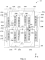
- FIG. 3 is a cross-sectional representation of one embodiment of the magnetic unit 100 of FIG. 1 according to aspects of the present specification.
- FIG. 3 is a cross-sectional view along the line 3-3 of FIG. 1 .
- the magnetic unit 100 includes the magnetic core 101.
- the magnetic core 101 includes three magnetic legs 102A, 102B, 102C.
- the magnetic leg 102A includes the first limb 202A and the second limb 204A.
- the magnetic leg 102B includes a first limb 202B and a second limb 204B and the magnetic leg 102C includes a first limb 202C and a second limb 204C.
- the first limbs 202A, 202B, and 202C form a first E-shaped sub-core 206.
- the second limbs 204A, 204B, and 204C form a second E-shaped sub-core 208.
- the first E-shaped sub-core 206 is aligned with the second E-shaped sub-core 208.
- each of the first limbs 202A, 202B, and 202C is aligned with corresponding second limbs 204A, 204B, and 204C.
- the first E-shaped sub-core 206 and the second E-shaped sub-core 208 together form a "E-E" shaped magnetic core 101 of the magnetic unit 100.
- the first air gap 106A is formed between the first limb 202A and the second limb 204A.
- the second air gap 106B is formed between the first limb 202B and the second limb 204B and the third air gap 106C is formed between the first limb 202C and the second limb 204C.
- Multiple turns of the first winding 104A may be wound on each of the first limbs 202A, 202B, 202C and multiple turns of the second winding 104B may be wound on each of the second limbs 204A, 204B, 204C.
- the conductive elements 108A and 108D are disposed at outer regions of the first and second E-shaped sub-cores 206, 208. More particularly, the conductive element 108A is disposed facing a portion of the outer periphery 203A of the first and second windings 104A, 104B wound on the leg 102A. Further, the conductive element 108D is disposed facing a portion of the outer periphery 203A of the first and second windings 104A, 104B wound on the leg 102C. The conductive element 108B is disposed between the magnetic legs 102A and 102B.
- the conductive element 108B is disposed facing a portion of the outer periphery 203A of the first and second windings 104A, 104B wound on the legs 102A, 102B. Further, the conductive element 108C is disposed between the magnetic legs 102B and 102C. Specifically, the conductive element 108C is disposed facing a portion of the outer periphery 203A of the first and second windings 104A, 104B wound on the legs 102B, 102C. Furthermore, at least a portion of the conductive elements 108A, 108B, 108C, and 108D are disposed facing the corresponding air gaps 106A, 106B, and 106C.
- each of the conductive elements 108A, 108B, 108C, 108D has a first portion 210A and two second portions 210B, 210C.
- the first portion 210A is formed between the two second portions 210B, 210C.
- the first portion 210A is disposed directly facing the air gap 106A.
- the second portions 210B, 210C are disposed at a determined distance from the air gap 106A.
- each of the conductive elements 108A, 108B, 108C, 108D has a non-uniform dimension along x-axis.
- the dimension of the first portion 210A along x-axis is about 2mm.
- the dimension of the second portions 210B, 210C along the x-axis is about 1 mm.
- the thickness of the first portion 210A of the conductive elements 108A, 108B, 108C, 108D facilitates enhanced heat dissipation.
- the conductive elements 108A, 108B, 108C, 108D have a uniform dimension. In such an embodiment, the dimension of each of the conductive elements 108A, 108B, 108C, 108D along the x-axis is about 2mm.
- the conductive elements 108A, 108B, 108C, 108D surround the air gaps 106A, 106B, or 106C.
- the conductive elements 108A, 108B, 108C, 108D are three-dimensional structures.
- each of the conductive elements 108A, 108B, 108C, 108D have a plurality of sections extending along different planes.
- each of the conductive elements 108A, 108B, 108C, 108D includes at least three sections disposed surrounding the corresponding air gap.
- each of the conductive elements 108A, 108B, 108C, 108D include first and second sections extending along the y-z plane and a third section extending along the x-y plane. In another embodiment, each of the conductive elements 108A, 108B, 108C, 108D includes only one section extending along the x-y plane.
- a fringing flux 212 is generated at the air gaps 106A, 106B, 106C.
- the fringing flux 212 generated only at the air gap 106C is depicted for ease of representation.
- the fringing flux 212 induces an eddy current 214 in the corresponding conductive element 108C.
- the eddy current 214 induced only at the conductive element 108C is depicted for ease of representation.
- the eddy current 214 induces a cancelation flux 216 according to Lenz's law.
- the cancelation flux 216 has a reverse polarity compared to the fringing flux 212.
- the fringing flux 212 may be controlled/reduced. Hence, magnitude of the eddy currents induced in the first and second windings 104A, 104B is reduced. Further, the first and second windings 104A, 104B are disposed at a determined distance from the corresponding air gap 106C. Hence, the eddy currents induced at the first and second windings 104A, 104B are reduced. Thus, copper losses in the first and second windings 104A, 104B are reduced. Thereby, the heat generated in the first and second windings 104A, 104B is reduced. Similarly, cancelation flux is generated at other air gaps.
- the magnetic unit 100 includes a heat sink 110.
- the conductive elements 108A, 108B, 108C, 108D are coupled to the heat sink 110.
- the heat sink 110 includes a heat pipe and a heat dissipation base.
- the conductive elements 108A, 108B, 108C, 108D are used to transfer generated heat to the heat sink 110.
- heat generated at the first and second windings 104A, 104B is transferred via thermal interface material (not shown in FIG. 3 ) including grease, epoxy, pad, other potting compounds, air, and the like to the conductive elements 108A, 108B, 108C, 108D and subsequently, transferred to the heat sink 110.
- thermal interface material not shown in FIG. 3
- FIG. 3 depicts the magnetic unit 100 having E-shaped sub-cores, the magnetic unit 100 having different sub-core shapes is envisaged.
- FIGs. 4-5 are cross-sectional representations of different embodiments of a magnetic unit 100 of FIG. 1 , according to aspects of the present specification.
- FIG. 4 represents cross-section of one embodiment of a magnetic unit 300.
- the magnetic unit 300 is a three-phase magnetic unit.
- the magnetic unit 300 includes the magnetic core 101.
- the magnetic core 101 includes three magnetic legs 102A, 102B, 102C.
- Each magnetic leg 102A, 102B, 102C has the first limb and the second limb and the air gap formed between the first limb and the second limb.
- the air gaps are represented by reference numerals 106A, 106B, 106C.
- the magnetic unit 300 includes conductive elements 302A, 302B, 302C, and 302D.
- the conductive elements 302A, 302B, 302C, and 302D are disposed facing the outer periphery (not shown in FIG. 4 ) of the first and second windings 104A, 104B. Additionally, at least a portion of the conductive elements 302A, 302B, 302C, and 302D are disposed facing the air gaps 106A, 106B, and 106C.
- Each of the conductive elements 302A, 302B, 302C, 302D are in form of a sheet. In the embodiment of FIG.
- each of the conductive elements 302A, 302B, 302C, 302D includes a first region 304A sandwiched between two second regions 304B.
- the second regions 304B include a plurality of slots 304C.
- the first region 304A is disposed directly facing the corresponding air gaps 106A, 106B, and 106C. Further, the second regions 304B are disposed at a determined distance from the air gaps 106A, 106B, and 106C.
- the thickness of the each of the conductive elements 302A, 302B, 302C, 302D along the x-axis is about 2mm.
- dimension of the conductive elements 302A, 302B, 302C, 302D along z-axis may be similar to the dimension of the magnetic legs 102A, 102B, 102C along the z-axis.
- the term 'dimension,' as used herein, may be used to refer to length, breadth/thickness, or height of the magnetic leg or the conductive element.
- the exemplary conductive elements 302A, 302B, 302C, 302D are lighter compared to the conductive elements 108A, 108B, 108C, and 108D of FIG. 1 due to presence of the slots 304C.
- the fringing flux is generated at the first, second, and third air gaps 106A, 106B, 106C.
- the fringing flux induces eddy currents in the conductive elements 302A, 302B, 302C, 302D.
- the eddy currents induce the cancelation flux according to Lenz's law.
- the cancelation flux has a reverse polarity compared to the fringing flux. In one example, at least some of the fringing flux is canceled. Accordingly, the fringing flux is controlled/reduced. Hence, magnitude of the eddy currents induced in the first and second windings 104A, 104B is reduced.
- first and second windings 104A, 104B are disposed at a determined distance from the corresponding air gaps 106A, 106B, 106C. Thus, copper losses in the first and second windings 104A, 104B is reduced.
- the magnetic unit 300 is disposed on the heat sink 110.
- the conductive elements 302A, 302B, 302C, 302D are coupled to the heat sink 110.
- the conductive elements 302A, 302B, 302C, 302D are used to transfer heat to the heat sink 110.
- heat generated at the first and second windings 104A, 104B is transferred via thermal interface material (not shown in FIG. 4 ) including grease, epoxy, pad, other potting compounds, air, and the like to the conductive elements 302A, 302B, 302C, 302D and subsequently, transferred to the heat sink 110.
- thermal interface material not shown in FIG. 4
- a magnetic unit 400 includes the magnetic core 101.
- the magnetic core 101 includes three magnetic legs 102A, 102B, 102C.
- Each magnetic leg 102A, 102B, 102C has the first limb and the second limb. Further, the air gap is formed between the first limb and the second limb.
- the air gaps are represented by reference numerals 106A, 106B, 106C.
- the magnetic unit 400 includes conductive elements 402A, 402B, 402C, 402D, 402E, 402F.
- the conductive elements 402A, 402B, 402C, 402D, 402E, 402F are disposed facing the outer periphery of at least one of the first and second windings 104A, 104B.
- the conductive elements 402A, 402B, 402C, 402D, 402E, 402F are disposed facing the outer peripheries 203B of the first and second windings 104A, 104B.
- the conductive elements 402A, 402B are sandwiched between the corresponding outer peripheries 203B of the first and second windings 104A, 104B of the first leg 102A.
- the conductive elements 402C, 402D are sandwiched between the corresponding outer peripheries 203B of the first and second windings 104A, 104B of the second leg 102B.
- the conductive elements 402E, 402F are sandwiched between the corresponding outer peripheries 203B of the first and second windings 104A, 104B of the third leg 102C.
- the conductive elements 402A, 402B, 402C, 402D, 402E, 402F are disposed facing the air gaps 106A, 106B, and 106C.
- the conductive elements 402A, 402B, 402C, 402D, 402E, 402F are wires or sheets formed as a loop.
- the conductive element 402A is disposed on one side of the air gap 106 A and the conductive element 402B is disposed on an opposite side of the air gap 106A.
- the conductive element 402C is disposed on one side of the air gap 106B and the conductive element 402D is disposed on an opposite side of the air gap 106B.
- the conductive element 402E is disposed on one side of the air gap 106C and the conductive element 402F is disposed on an opposite side of the air gap 106C.
- the fringing flux is generated at the air gaps 106A, 106B, 106C.
- the fringing flux induces eddy currents in the conductive elements 402A, 402B, 402C, 402D, 402E, 402F.
- the eddy currents in the conductive elements 402A, 402B, 402C, 402D, 402E, 402F heats the conductive elements 402A, 402B, 402C, 402D, 402E, 402F.
- the eddy currents in the conductive elements 402A, 402B, 402C, 402D, 402E, 402F induce cancelation flux at the corresponding air gaps 106A, 106B, 106C.
- the cancelation flux at the air gaps 106A, 106B, 106C reduces the fringing flux.
- magnitude of the eddy currents induced in the first and second windings 104A, 104B is reduced.
- the first and second windings 104A, 104B are disposed at a determined distance from the corresponding air gaps 106A, 106B, 106C.
- copper losses of the first and second windings 104A, 104B are reduced.
- a resistor 404 is coupled to each of the conductive elements 402A, 402B, 402C, 402D, 402E, 402F.
- the resistor 404 may be disposed at a predetermined distance from each of the conductive elements 402A, 402B, 402C, 402D, 402E, 402F. Eddy currents flowing through the conductive elements 402A, 402B, 402C, 402D, 402E, 402F dissipates heat at the corresponding resistor 404.
- the magnetic unit 400 includes the heat sink (not shown).
- the conductive elements 402A, 402B, 402C, 402D, 402E, 402F are coupled to the heat sink.
- the conductive elements 402A, 402B, 402C, 402D, 402E, 402F are used to transfer heat to the heat sink, either directly or through the corresponding resistors 404.
- heat generated at the windings 104A, 104B is transferred via thermal interface material (not shown in FIG. 5 ) including grease, epoxy, pad, other potting compounds, air, and the like to the corresponding conductive elements 402A, 402B, 402C, 402D, 402E, 402F and subsequently transferred to the heat sink.
- FIG. 5 depicts two conductive elements disposed facing each air gap, in other embodiments, the number of conductive elements disposed facing each air gap may vary depending on application.
- FIG. 6 is a cross-sectional representation of a magnetic unit 450 according to aspects of the present specification.
- the magnetic unit 450 includes three first limbs 452A, 452B, 452C and a second limb 452D.
- the first limbs 452A, 452B, 452C form a E-shaped sub-core and the second limb 452D forms a I-shaped sub-core.
- the first limbs 452A, 452B, 452C and the second limb 452D together form an "E-I" shaped magnetic core.
- a gap 454A is formed between a first portion of the second limb 452D and the first limb 452A.
- a gap 454B is formed between a second portion of the second limb 452D and the first limb 452B.
- a gap 454C is formed between a third portion of the second limb 452D and the first limb 452C.
- the gaps 454A, 454B 454C may be referred to as air gaps.
- a winding 456 is wound on each of the first limbs 452A, 452B, 452C.
- the winding 456 includes outer peripheries 458A and 458B and an inner periphery 458C.
- the inner periphery 458C directly faces the corresponding first limbs 452A, 452B, 452C.
- the exemplary magnetic unit 450 includes a plurality of conductive elements 460.
- Each conductive element 460 is disposed facing the outer periphery 458A of the corresponding winding 456.
- each conductive element 460 includes a first portion 460A and a second portion 460B.
- the first portion 460A is thicker compared to the second portion 460B.
- the first portion 460A has a dimension of 2mm along the x-axis and the second portion 460B has a dimension of 1mm along x-axis.
- the term 'dimension,' as used herein, may be used to refer to length, breadth/thickness, or height of the first or second portions of the conductive element.
- Each first portion 460A is disposed directly facing the corresponding air gaps 454A, 454B, 454C.
- a fringing flux is generated at the air gaps 454A, 454B, 454C.
- the fringing flux induces eddy currents in the corresponding conductive elements 460.
- the eddy currents in the conductive elements 460 heats the conductive elements 460.
- the eddy currents in the conductive elements 460 induces cancelation flux at the corresponding air gaps 454A, 454B, 454C.
- the cancelation flux at the air gaps 454A, 454B, 454C in turn reduces the fringing flux.
- magnitude of the eddy currents induced in the windings 456 is reduced.
- copper losses of the windings 456 are reduced.
- the magnetic unit 450 includes a heat sink 462.
- the conductive elements 460 are coupled to the heat sink 462.
- the conductive elements 460 are used to transfer heat of the conductive elements 460 to the heat sink 462.
- heat generated at the windings 456 is transferred via thermal interface material (not shown in FIG. 6 ) including grease, epoxy, pad, other potting compounds, air, and the like to the corresponding conductive elements 460 and subsequently transferred to the heat sink 462.
- FIG. 7 is a perspective view of a thermal management device 500 of the magnetic unit of FIG. 1 , according to aspects of the present specification.
- FIG. 7 represents a portion of the magnetic unit 100 of FIG. 1 .
- the thermal management device 500 includes a combination of the heat sink 110 and the conductive elements 108B, 108C and heat dissipation elements 108E, 108F.
- the heat sink 110 includes a heat dissipation base 112 and a heat pipe 504.
- the heat dissipation base 112 has a first surface 506A and an opposite second surface 506B.
- the conductive elements 108B and 108C are disposed on the first surface 506A of the heat dissipation base 112 and heat dissipation elements 108E and 108F are disposed on the second surface 506B of the heat dissipation base 112.
- the heat dissipation elements 108E and 108F are thermally conductive elements.
- the heat dissipation elements 108E and 108F are electrically conductive in addition to being thermally conductive.
- the second surface 506B may be subjected to forced/natural convection using air/liquid as media.
- the second surface 506B may be conductively coupled to another heat sink.
- the heat dissipation base 112 includes internal channels 510, where the internal channels 510 are configured to allow flow of a coolant.
- a direction of flow of the coolant into the heat dissipation base 112 is represented using a reference numeral 508A.
- a direction flow of the coolant from the heat dissipation base 112 is represented using a reference numeral 508B.
- the coolant may be any fluid media, such as, but not limited to air and water.
- the internal channels 510 of the heat dissipation base 112 aid in enhanced heat dissipation.
- the internal channels 510 of the heat dissipation base 112 includes surface area enhancing design features such as fins, studs, ribs to enhance surface area for heat dissipation.
- the conductive elements 108B, 108C and the heat dissipation elements 108E, 108F may include surface area enhancing features such as studs, pin fins, ribs, and the like for heat dissipation.
- the heat pipe 504 may be disposed on at least one of the heat dissipation base 112, the conductive elements 108B, 108C, and the heat dissipation elements 108E, 108F. In the example of FIG. 7 , the heat pipe 504 is embedded in the heat dissipation base 112 and the conductive elements 108B, 108C. In one embodiment, a heat pipe may be embedded in the heat dissipation elements 108E, 108F.
- the heat pipe 504 may be copper pipe having water, an aluminum pipe having acetone, or the like.
- the conductive elements 108B, 108C and the heat sink 110 are separate elements.
- the conductive elements 108B, 108C may be coupled to the heat sink 110 using adhesives, threaded fasteners, bolts, welding, brazing, and the like.
- the thermal management device 500 having the conductive elements 108B, 108C and the heat sink 110 is a monolithic structure.
- the term "monolithic structure" refers to a continuous structure that is substantially free of any joints.
- the monolithic structure may be a unitary structure devoid of any joined parts or layers.
- the monolithic thermal management device 500 may be formed as one structure during processing, without any brazing or multiple sintering steps.
- the thermal management device 500 is a monolithic 3D vapor chamber.
- FIG. 7 depicts only two conductive elements, in other embodiments, the number of conductive elements may vary based on the application. Also, although the example of FIG. 7 depicts the heat pipe being disposed only on one conductive element, in another embodiment, the heat pipe may be disposed on all the conductive elements in another embodiment.
- FIG. 8 is a cross-sectional representation of another embodiment of a magnetic unit 550 according to aspects of the present specification.
- the magnetic unit 550 includes a magnetic core 551 having a first limb 552, a second limb 554, and branches 556, 558.
- One end of the first limb 552 is coupled to one end of the second limb 554 via the branch 556. Further, other end of the first limb 552 is coupled to other end of the second limb 554 via the branch 558.
- a first winding 560 is wound around the first limb 552. Further, a second winding 562 is wound on the second limb 554. Furthermore, a third winding 564 is wound on the first limb 552 and a fourth winding 566 is wound on the second limb 554. The third winding 564 is sandwiched between the first winding 560 and the first limb 552. The fourth winding 566 is sandwiched between the second winding 562 and the second limb 554. The third and fourth windings 564, 566 form primary windings of the magnetic unit 550. The first and second windings 560, 562 form secondary windings of the magnetic unit 550.
- a gap 568 is formed between the first limb 552 and the second limb 554.
- a fringing flux is generated between the windings 560, 564 wound on the first limb 552 and the windings 562, 566 wound on the second limb 554. In one embodiment, the fringing flux is generated between the first winding 560 and the second winding 562.
- a conductive element 570 similar to the conductive elements 108A, 108B, 108C, or 108 D of FIG. 1 , is disposed within the gap 568.
- at least a portion of the conductive element 570 is disposed facing at least a portion of an outer periphery 572 of the first winding 560 and at least a portion of an outer periphery 574 of the second winding 562.
- the use of the conductive element 570 aids in controlling/reducing the fringing flux generated between the windings 560, 564, 562, 566 wound on the first and second limbs 552, 554.
- the conductive element 570 may be coupled to a heat sink (not shown in FIG. 8 ) similar to the heat sink 110 of FIG. 1 . Further, the conductive element 570 is configured to dissipate heat generated at at least one of the conductive element 570 and the windings 560 562, 564, 566 to the heat sink.
- FIG. 9 is a block diagram of a power conversion system 600 having the magnetic unit 100 of FIG. 1 , according to aspects of the present specification.
- the power conversion system 600 includes a power source/generator 602, a converter 604, the magnetic unit 100, and a load 606.
- the power source/generator 602 is coupled to the converter 604. Further, the converter 604 is coupled to the magnetic unit 100 which in turn is coupled to the load 606.
- the power source/generator 602 may be an alternating current (AC) power source, a direct current (DC) power source, or the like.
- the power source/generator 602 may be a solar panel, a wind turbine, or the like.
- the converter 604 may be a AC to AC power converter, a DC to AC converter, or the like.
- the term 'converter' as used herein, refers to an electrical or electro-mechanical device used for converting electrical energy from one form to another.
- the magnetic unit 100 is an inductor, a transformer, or the like.
- the exemplary magnetic unit 100 has a magnetic core having a gap defined therein.
- the magnetic unit 100 includes conductive elements disposed facing the gap.
- the conductive elements are disposed within the gap. The conductive elements are used to reduce heating of the windings due to the fringing flux and transfer heat generated at the conductive elements and the windings to the heat sink.
- an input voltage is provided to the converter 604 from the power source/generator 602.
- the input voltage is converted by the converter 604 to an output voltage having a determined frequency and magnitude.
- the output voltage is further transmitted to the magnetic unit 100.
- the magnetic unit 100 is configured to step up the input voltage and generate a stepped-up voltage.
- the stepped-up voltage is further provided to the load 606.
- the load 606 includes a motor.
- the exemplary power conversion system 600 may be used in an aircraft electrical system, a locomotive electrical system, a renewable power system, and the like.
- FIG. 10 is a flow chart 700 representing a method for operation of the magnetic unit of FIG. 1 according to aspects of the present specification.
- fringing flux is generated at the air gap formed between the first limb and the second limb of the magnetic leg during operation of the magnetic unit.
- the fringing flux is generated at the air gap due to electrical energization of the magnetic unit.
- the fringing flux is generated at the air gap due to a current provided to the magnetic unit.
- a fringing flux may be generated between the windings wound on the first limb and the second limb during operation of the magnetic unit.
- a current is induced at the conductive element disposed facing the outer periphery of the windings.
- the current is induced at the conductive element based on the fringing flux in accordance with Lenz's law.
- the current induced at the conductive element may also be referred to as the eddy current.
- the cancelation flux is induced at the gap between the first limb and the second limb based on the eddy current induced in the conductive element.
- the cancelation flux is induced at the gap between windings wound on the first limb and the second limb based on the eddy current induced in the conductive element.
- the cancelation flux has a reverse polarity compared to the fringing flux. As a result, at least a portion of the fringing flux is canceled. As a result, magnitude of the eddy currents induced in the windings is reduced. Thereby, the copper losses in the windings are reduced.
- heat from at least one of the conductive element and the first winding is transferred to a heat sink.
- heat generated at the first and second windings is transferred to the heat sink.
- the heat generated at the first and second windings is transferred via thermal interface material including grease, epoxy, pad, other potting compounds, air, and the like to the conductive element and subsequently, to the heat sink by conduction.
- an exemplary magnetic unit having a magnetic core, a plurality of windings, and a conductive element.
- the magnetic unit has a magnetic core having one or more gaps defined therein.
- the exemplary magnetic unit has conductive elements which aids in reducing winding copper losses due to the fringing flux.
- the conductive element in combination with the heat sink of the magnetic unit aids in enhanced heat dissipation. Accordingly, the temperature of the magnetic unit is reduced considerably.
- the different features and structures of the various embodiments of the present disclosure may be used in combination with each other as desired.
- one or more of the features illustrated and/or described with respect to one of the examples, features, elements, or aspects can be used with or combined with one or more examples, features, elements, or aspects illustrated and/or described with respect to the other of the examples, features, elements, or aspects. That one feature may not be illustrated in all of the embodiments is not meant to be construed that it cannot be, but is done for brevity of description.
- the various features of the different embodiments may be mixed and matched as desired to form new embodiments, whether or not the new embodiments are expressly described.
Landscapes
- Engineering & Computer Science (AREA)
- Power Engineering (AREA)
- Chemical & Material Sciences (AREA)
- Composite Materials (AREA)
- Coils Of Transformers For General Uses (AREA)
Abstract
Description
- This application claims priority to
U.S. Patent Application No. 16/007,844, filed June 13, 2018 , the entirety of which is incorporated herein by reference. - This disclosure generally relates to a magnetic unit for power conversion, which includes a gapped core for reducing the local fringing flux to provide for more efficient operation.
- Embodiments of the present specification generally relate to a magnetic unit and method of operation of the magnetic unit, and more particularly, to a gapped magnetic unit having reduced winding losses for high frequency power conversion applications.
- As will be appreciated, power conversion applications, such as, motor drives, backup electrical power supplies, and the like use magnetic units, such as inductors/transformers and pulse width modulated (PWM) inverters/converters. The PWM inverters/converters typically generate high frequency switching signals. In order to attenuate the high frequency switching signals generated by the PWM inverter/converter, gapped magnetic units are employed instead of solid core magnetic units. The gapped magnetic unit includes a magnetic core having an air gap and copper wire windings wound on the magnetic core. The gapped magnetic units are prone to fringing flux at air gaps. The fringing flux at the air gap induces eddy currents in the copper wire windings. Accordingly, the copper wire windings are subjected to higher thermal losses.
- In recent times, use of litz wire as windings instead of copper wires has been proposed. The litz wire reduces copper losses caused due to fringing flux. However, the litz wire has many insulation layers, which increases physical size of the wire itself. As a result, footprint of the magnetic core increases in order to accommodate the litz wire windings.
- Also, recently, use of magnetic core having distributed air gaps have been proposed to reduce copper losses resulting due to fringing flux. However, cost of manufacture of the magnetic core having distributed air gaps is relatively high.
- Therefore, there is a need for an enhanced gapped magnetic unit for reducing winding losses for high frequency power conversion applications.
- In accordance with one aspect of the present specification, a magnetic unit is presented. The magnetic unit includes a magnetic core. The magnetic core includes a first limb and a second limb disposed proximate to the first limb, where a gap is formed between the first limb and the second limb. The magnetic unit further includes a first winding wound on the first limb. Moreover, the magnetic unit includes a conductive element disposed facing an outer periphery of the first winding, where the conductive element is configured to control a fringing flux generated at the gap. Further, the magnetic unit includes a heat sink operatively coupled to the conductive element, wherein the conductive element is further configured to transfer heat from at least one of the conductive element and the first winding to the heat sink.
- In accordance with another aspect of the present specification, a high frequency power conversion system is presented. The high frequency power conversion system includes a converter. Further, the high frequency power conversion system includes a magnetic unit operatively coupled to the converter, where the magnetic unit includes a magnetic core. The magnetic core includes a first limb and a second limb disposed proximate to the first limb, where a gap is formed between the first limb and the second limb. Furthermore, the magnetic unit includes a first winding wound on the first limb. Moreover, the magnetic unit includes a conductive element disposed facing an outer periphery of the first winding, where the conductive element is configured to control a fringing flux generated at the gap. Further, the magnetic unit includes a heat sink operatively coupled to the conductive element, wherein the conductive element is further configured to transfer heat from at least one of the conductive element and the first winding to the heat sink.
- In accordance with yet another aspect of the present specification, a method of operation of a magnetic unit is presented. The method includes generating a fringing flux at a gap formed between a first limb and a second limb. The method further includes inducing a current in a conductive element disposed facing an outer periphery of the first winding, based on the fringing flux. Moreover, the method includes generating a cancelation flux at the gap based on the current in the conductive element to control the fringing flux. Further, the method includes transferring heat from at least one of the conductive element and the first winding to a heat sink.
- These and other features, aspects, and advantages of the present disclosure will become better understood when the following detailed description is read with reference to the accompanying drawings in which like characters represent like parts throughout the drawings, wherein:
-
FIG. 1 is a perspective view of a magnetic unit according to aspects of the present specification; -
FIG. 2 is a cross-sectional representation of a portion of a magnetic unit ofFIG. 1 according to aspects of the present specification; -
FIGs. 3-5 are cross-sectional representations of different embodiments of a magnetic unit according to aspects of the present specification; -
FIG. 6 is a cross-sectional representation of one embodiment of a magnetic unit according to aspects of the present specification; -
FIG. 7 is a perspective view of a thermal management device of the magnetic unit ofFIG. 1 according to aspects of the present specification; -
FIG. 8 is a cross-sectional representation of another embodiment of a magnetic unit according to aspects of the present specification; -
FIG. 9 is a block diagram of a power conversion system using the magnetic unit ofFIG. 1 according to aspects of the present specification; and -
FIG. 10 is a flow chart representing a method for operation of the magnetic unit ofFIG. 1 according to aspects of the present specification. - Unless defined otherwise, technical and scientific terms used herein have the same meaning as is commonly understood by one of ordinary skill in the art to which this disclosure belongs. The terms "first," "second," and the like, as used herein do not denote any order, quantity, or importance, but rather are used to distinguish one element from another. Also, the terms "a" and "an" do not denote a limitation of quantity, but rather denote the presence of at least one of the referenced items. The use of "including," "comprising" or "having" and variations thereof herein are meant to encompass the items listed thereafter and equivalents thereof as well as additional items. The terms "connected" and "coupled" are not restricted to physical or mechanical connections or couplings, and can include electrical connections or couplings, whether direct or indirect. The term "operatively coupled," as used herein, refers to direct and indirect coupling. Furthermore, the terms "circuit" and "circuitry" and "controller" may include either a single component or a plurality of components, which are either active and/or passive and are connected or otherwise coupled together to provide the described function.
- As will be described in detail hereinafter, various embodiments of a magnetic unit, a power conversion system employing the magnetic unit, and a method for operation of the magnetic unit are disclosed. The exemplary magnetic unit may be employed in high frequency power conversion applications, such as locomotives, aircrafts, renewable power generation systems, hybrid electrical vehicles, and the like.
- The magnetic unit may be an inductor or a transformer. The exemplary magnetic unit includes a magnetic core, a plurality of windings, and a conductive element. The magnetic core may be a gapped magnetic core or a solid magnetic core. The gapped magnetic core may have one or more gaps. The gaps of the gapped magnetic core may also be referred to as air gaps. The term 'air gap,' as used herein, refers to a non-magnetic region of the magnetic core. Use of the gapped magnetic core results in generation of a fringing flux in the gaps during operation of the magnetic unit. Further, a fringing flux may be generated between windings wound on limbs of the magnetic core, where the limbs are separated from each other by a gap. In particular, the limbs are placed a determined distance apart from each other. The term 'fringing flux,' as used herein, refers to a phenomenon in which a magnetic flux flowing in a magnetic core, spreads out (or fringes out) into a surrounding medium, for example, in and around the gap.
- According to aspects of the present specification, the magnetic unit includes a conductive element. The conductive element is electrically and thermally conductive. The electrically conductive element allows flow of an electrical current in one or more directions. The thermally conductive element allows transfer of heat. The use of the conductive element aids in reducing copper losses due to fringing flux generated at the air gap of the magnetic core. Further, use of the conductive element aids in reducing copper losses due to the fringing flux generated between the windings wound on limbs of the magnetic core. Furthermore, use of the conductive element aids in transfer of heat to a heat sink thus providing an enhanced thermal management. The exemplary magnetic unit provides a low-cost and compact solution for reduction of copper losses due to the fringing flux. The term 'copper losses,' as used herein, refers to heat produced by electrical current flowing in windings of transformers or other electrical devices/elements.
- Turning now to the drawings,
FIG. 1 is a perspective view of amagnetic unit 100 according to aspects of the present specification. Themagnetic unit 100 is a three-phase magnetic unit. Themagnetic unit 100 includes amagnetic core 101. Themagnetic core 101 includes a firstmagnetic leg 102A, a secondmagnetic leg 102B, and a thirdmagnetic leg 102C. - Each of the
magnetic legs FIG. 1 ) and a second limb (not shown inFIG. 1 ). A first winding 104A is wound on the first limb of each of themagnetic legs magnetic legs FIG. 1 , the first andsecond windings second windings magnetic legs second windings - In one embodiment, the first and
second windings second windings second windings - In one embodiment, a gap is formed between the first and second limbs of each of the
magnetic legs magnetic legs magnetic legs reference numerals - It may be noted that during operation of a conventional gapped magnetic unit, a fringing flux is generated at the air gap. In conventional gapped magnetic units, windings are disposed facing or proximate to the air gaps. Hence, the fringing flux tends to induce high magnitude eddy current in the windings. The high magnitude of the eddy current results in higher copper losses in the windings. The term 'eddy current,' as used herein, refers to a localized electrical current induced in a conductor by a varying magnetic field.
- In accordance with aspects of the present specification, the first and
second windings air gaps conductive elements FIG. 1 ) of at least one of the first andsecond windings conductive elements FIG. 1 ) of at least one the first andsecond windings magnetic legs - In one embodiment, the
conductive elements air gaps conductive elements air gaps conductive elements air gaps magnetic unit 100. - The
conductive elements conductive elements conductive elements conductive elements conductive elements - A fringing flux is generated at the
air gaps magnetic unit 100. Further, in one embodiment, a fringing flux may be generated between thefirst windings 104A and/or thesecond windings 104B of themagnetic legs second windings corresponding air gaps second windings second windings - Furthermore, as noted hereinabove, the
magnetic unit 100 includes theconductive elements air gaps conductive elements first windings 104A and/or thesecond windings 104B induces eddy currents at theconductive elements conductive elements conductive elements conductive elements corresponding air gaps second windings second windings - In accordance with aspects of the present specification, the
magnetic unit 100 further includes aheat sink 110. A combination of theheat sink 110 and theconductive elements conductive elements heat sink 110. The term 'heat sink,' as used herein, refers to a heat exchanger that transfers heat generated by an electronic, an electrical, or a mechanical device to a fluid medium, such as air or a liquid coolant, where heat is dissipated away from the device, thereby allowing regulation of the temperature of the device. - According to aspects of the present specification, the
heat sink 110 includes heat pipes (not shown inFIG. 1 ) and aheat dissipation base 112. In accordance with aspects of the present specification, theconductive elements heat sink 110 and specifically, to theheat dissipation base 112. Theconductive elements heat sink 110. In one embodiment, the heat generated at the first andsecond windings conductive elements second windings conductive elements conductive elements heat sink 110 by conduction. Therefore, theconductive elements windings air gaps - Although the example of
FIG. 1 depicts a three-phase magnetic unit, use of a single phase magnetic unit having a magnetic core having a single magnetic leg is also envisioned. In another embodiment, use of multi-phase magnetic units is envisioned. Also, althoughFIG. 1 depicts densely packed windings on each limb of a magnetic leg, use of sparsely packed windings on each limb of the magnetic leg is envisaged. - Although example of
FIG. 1 depicts each limb having a corresponding winding, in certain embodiments, limbs devoid of windings are envisaged. Furthermore, although in the example ofFIG. 1 , magnetic core includes three first limbs and three second limbs, in other embodiments, the number of limbs may vary. In one embodiment, a magnetic core may include three first limbs and one second limb. - Referring now to
FIG. 2 , a cross-sectional representation of a portion of amagnetic unit 100, according to aspects of the present specification is shown. In particular,FIG. 2 is a cross-sectional view along the line 2-2 ofFIG. 1 . More particularly,FIG. 2 represents specifically a cross-section of a singlemagnetic leg 102A of themagnetic unit 100. Themagnetic leg 102A includes afirst limb 202A and asecond limb 204A. Thefirst limb 202A is disposed proximate to thesecond limb 204A such that theair gap 106A is formed between the first andsecond limbs FIG. 2 , thefirst limb 202A is aligned with thesecond limb 204A. The phrase 'first limb 202A aligned with thesecond limb 204A' refers to alignment of a central axis of thefirst limb 202A with a central axis of thesecond limb 204A. The term 'central axis of thefirst limb 202A' refers to an axis passing through a center of gravity of thefirst limb 202A along a y-axis direction. In a similar manner, the term 'central axis of thesecond limb 204A' refers to an axis passing through a center of gravity of thesecond limb 204A along the y-axis direction. - Further, the
first limb 202A and thesecond limb 204A are made of magnetic materials having relatively high magnetic permeability. In one embodiment, thefirst limb 202A and thesecond limb 204A are made of materials such as ferrite. Moreover, multiple turns of the winding 104A are wound on thefirst limb 202A and multiple turns of the winding 104B are wound on thesecond limb 204A. Number of turns of the first andsecond windings second limbs - The
windings outer peripheries inner periphery 203C. Theinner periphery 203C of thewindings 104Afirst limb 202A and thesecond limb 204A of themagnetic leg 102A. - As previously noted, during operation of the
magnetic unit 100, the fringing flux is generated at theair gap 106A. In conventional gapped magnetic units, fringing flux tends to induce eddy currents in windings. The eddy current results in high copper losses in the winding. - In accordance with aspects of the present specification, the first winding 104A is disposed at a
determined distance 205A from theair gap 106A. Also, the second winding 104B is disposed at adetermined distance 205B from theair gap 106A. In one embodiment, thedetermined distances air gap 106A induces eddy currents of lower magnitude in the first winding 104A compared to the conventional gapped magnetic unit where the windings are disposed directly facing the air gap. Hence, the copper losses in the first andsecond windings determined distances - Further, the exemplary
magnetic unit 100 includes theconductive element 108A. Theconductive element 108A is disposed facing theouter periphery 203A of the first andsecond windings conductive element 108A is disposed facing theair gap 106A. - As noted hereinabove, the fringing flux is generated at the
air gap 106A. As a result, the eddy current is induced at theconductive element 108A. The eddy current induced at theconductive element 108A heats up theconductive element 108A. As a result of the eddy current induced at theconductive element 108A, the cancelation flux is induced at theair gap 106A according to Lenz's law. Hence, at least a portion of the fringing flux is canceled and thereby, the magnitude of the fringing flux is reduced. As a result, the magnitude of the eddy currents induced in the first andsecond windings second windings second windings second windings second windings FIG. 2 ) including grease, epoxy, pad, other potting compounds, air, and the like to theconductive element 108A. Theconductive element 108A is configured to transfer heat to the heat sink by conduction. The structure of the heat sink will be described in greater detail below with respect toFIG. 7 . -
FIG. 3 is a cross-sectional representation of one embodiment of themagnetic unit 100 ofFIG. 1 according to aspects of the present specification. In particular,FIG. 3 is a cross-sectional view along the line 3-3 ofFIG. 1 . Themagnetic unit 100 includes themagnetic core 101. Themagnetic core 101 includes threemagnetic legs magnetic leg 102A includes thefirst limb 202A and thesecond limb 204A. Similarly, themagnetic leg 102B includes afirst limb 202B and asecond limb 204B and themagnetic leg 102C includes afirst limb 202C and asecond limb 204C. Thefirst limbs E-shaped sub-core 206. Further, thesecond limbs E-shaped sub-core 208. In the illustrated embodiment ofFIG. 2 , the firstE-shaped sub-core 206 is aligned with the secondE-shaped sub-core 208. In particular, each of thefirst limbs second limbs E-shaped sub-core 206 and the secondE-shaped sub-core 208 together form a "E-E" shapedmagnetic core 101 of themagnetic unit 100. - The
first air gap 106A is formed between thefirst limb 202A and thesecond limb 204A. Similarly, thesecond air gap 106B is formed between thefirst limb 202B and thesecond limb 204B and thethird air gap 106C is formed between thefirst limb 202C and thesecond limb 204C. Multiple turns of the first winding 104A may be wound on each of thefirst limbs second limbs - In the illustrated embodiment of
FIG. 3 , theconductive elements E-shaped sub-cores conductive element 108A is disposed facing a portion of theouter periphery 203A of the first andsecond windings leg 102A. Further, theconductive element 108D is disposed facing a portion of theouter periphery 203A of the first andsecond windings leg 102C. Theconductive element 108B is disposed between themagnetic legs conductive element 108B is disposed facing a portion of theouter periphery 203A of the first andsecond windings legs conductive element 108C is disposed between themagnetic legs conductive element 108C is disposed facing a portion of theouter periphery 203A of the first andsecond windings legs conductive elements air gaps - Further, the dimension of the
conductive elements magnetic legs conductive elements first portion 210A and twosecond portions first portion 210A is formed between the twosecond portions first portion 210A is disposed directly facing theair gap 106A. Thesecond portions air gap 106A. - Furthermore, each of the
conductive elements first portion 210A along x-axis is about 2mm. Further, the dimension of thesecond portions first portion 210A of theconductive elements conductive elements conductive elements - In one embodiment, the
conductive elements air gaps conductive elements conductive elements conductive elements conductive elements conductive elements - During operation of the
magnetic unit 100, afringing flux 212 is generated at theair gaps FIG. 3 , thefringing flux 212 generated only at theair gap 106C is depicted for ease of representation. Thefringing flux 212 induces aneddy current 214 in the correspondingconductive element 108C. Theeddy current 214 induced only at theconductive element 108C is depicted for ease of representation. Theeddy current 214 induces acancelation flux 216 according to Lenz's law. Thecancelation flux 216 has a reverse polarity compared to thefringing flux 212. In one example, at least a portion of thefringing flux 212 is canceled. Accordingly, thefringing flux 212 may be controlled/reduced. Hence, magnitude of the eddy currents induced in the first andsecond windings second windings air gap 106C. Hence, the eddy currents induced at the first andsecond windings second windings second windings - Additionally, the
magnetic unit 100 includes aheat sink 110. Theconductive elements heat sink 110. As noted hereinabove, theheat sink 110 includes a heat pipe and a heat dissipation base. Theconductive elements heat sink 110. In addition, heat generated at the first andsecond windings FIG. 3 ) including grease, epoxy, pad, other potting compounds, air, and the like to theconductive elements heat sink 110. Although the example ofFIG. 3 depicts themagnetic unit 100 having E-shaped sub-cores, themagnetic unit 100 having different sub-core shapes is envisaged. -
FIGs. 4-5 are cross-sectional representations of different embodiments of amagnetic unit 100 ofFIG. 1 , according to aspects of the present specification. In particular,FIG. 4 represents cross-section of one embodiment of amagnetic unit 300. Themagnetic unit 300 is a three-phase magnetic unit. Themagnetic unit 300 includes themagnetic core 101. Themagnetic core 101 includes threemagnetic legs magnetic leg reference numerals - According to aspects of the present specification, the
magnetic unit 300 includesconductive elements conductive elements FIG. 4 ) of the first andsecond windings conductive elements air gaps conductive elements FIG. 4 , each of theconductive elements first region 304A sandwiched between twosecond regions 304B. Thesecond regions 304B include a plurality ofslots 304C. Thefirst region 304A is disposed directly facing the correspondingair gaps second regions 304B are disposed at a determined distance from theair gaps conductive elements conductive elements magnetic legs conductive elements conductive elements FIG. 1 due to presence of theslots 304C. - During operation of the
magnetic unit 300, the fringing flux is generated at the first, second, andthird air gaps conductive elements second windings second windings air gaps second windings - Additionally, the
magnetic unit 300 is disposed on theheat sink 110. Theconductive elements heat sink 110. Theconductive elements heat sink 110. In addition, heat generated at the first andsecond windings FIG. 4 ) including grease, epoxy, pad, other potting compounds, air, and the like to theconductive elements heat sink 110. Thus, temperature of themagnetic unit 300 is maintained at an optimal value. - Referring now to
FIG. 5 , a cross-section of one embodiment of amagnetic unit 100 ofFIG. 1 is shown. Amagnetic unit 400 includes themagnetic core 101. Themagnetic core 101 includes threemagnetic legs magnetic leg reference numerals - The
magnetic unit 400 includesconductive elements conductive elements second windings conductive elements outer peripheries 203B of the first andsecond windings conductive elements outer peripheries 203B of the first andsecond windings first leg 102A. In a similar manner, theconductive elements outer peripheries 203B of the first andsecond windings second leg 102B. Further, theconductive elements outer peripheries 203B of the first andsecond windings third leg 102C. - Additionally, at least a portion of the
conductive elements air gaps conductive elements conductive element 402A is disposed on one side of theair gap 106 A and theconductive element 402B is disposed on an opposite side of theair gap 106A. Further, theconductive element 402C is disposed on one side of theair gap 106B and theconductive element 402D is disposed on an opposite side of theair gap 106B. Furthermore, theconductive element 402E is disposed on one side of theair gap 106C and theconductive element 402F is disposed on an opposite side of theair gap 106C. - As noted hereinabove, during operation of the
magnetic unit 400, the fringing flux is generated at theair gaps conductive elements conductive elements conductive elements conductive elements corresponding air gaps air gaps second windings second windings air gaps second windings - In the embodiment of
FIG. 5 , aresistor 404 is coupled to each of theconductive elements resistor 404 may be disposed at a predetermined distance from each of theconductive elements conductive elements corresponding resistor 404. - Further, the
magnetic unit 400 includes the heat sink (not shown). Theconductive elements conductive elements resistors 404. In addition, heat generated at thewindings FIG. 5 ) including grease, epoxy, pad, other potting compounds, air, and the like to the correspondingconductive elements - Although the example of
FIG. 5 depicts two conductive elements disposed facing each air gap, in other embodiments, the number of conductive elements disposed facing each air gap may vary depending on application. -
FIG. 6 is a cross-sectional representation of amagnetic unit 450 according to aspects of the present specification. Themagnetic unit 450 includes threefirst limbs second limb 452D. Thefirst limbs second limb 452D forms a I-shaped sub-core. Thefirst limbs second limb 452D together form an "E-I" shaped magnetic core. - Further, a
gap 454A is formed between a first portion of thesecond limb 452D and thefirst limb 452A. Further, agap 454B is formed between a second portion of thesecond limb 452D and thefirst limb 452B. Moreover, agap 454C is formed between a third portion of thesecond limb 452D and thefirst limb 452C. Thegaps 454B 454C may be referred to as air gaps. - In the illustrated embodiment of
FIG. 6 , a winding 456 is wound on each of thefirst limbs outer peripheries inner periphery 458C. Theinner periphery 458C directly faces the correspondingfirst limbs - Furthermore, the exemplary
magnetic unit 450 includes a plurality ofconductive elements 460. Eachconductive element 460 is disposed facing theouter periphery 458A of the corresponding winding 456. Further, eachconductive element 460 includes afirst portion 460A and asecond portion 460B. Thefirst portion 460A is thicker compared to thesecond portion 460B. In one embodiment, thefirst portion 460A has a dimension of 2mm along the x-axis and thesecond portion 460B has a dimension of 1mm along x-axis. The term 'dimension,' as used herein, may be used to refer to length, breadth/thickness, or height of the first or second portions of the conductive element. Eachfirst portion 460A is disposed directly facing the correspondingair gaps - During operation of the
magnetic unit 450, a fringing flux is generated at theair gaps conductive elements 460. The eddy currents in theconductive elements 460 heats theconductive elements 460. Further, the eddy currents in theconductive elements 460 induces cancelation flux at thecorresponding air gaps air gaps windings 456 is reduced. Thus, copper losses of thewindings 456 are reduced. - Further, the
magnetic unit 450 includes aheat sink 462. Theconductive elements 460 are coupled to theheat sink 462. Theconductive elements 460 are used to transfer heat of theconductive elements 460 to theheat sink 462. In addition, heat generated at thewindings 456 is transferred via thermal interface material (not shown inFIG. 6 ) including grease, epoxy, pad, other potting compounds, air, and the like to the correspondingconductive elements 460 and subsequently transferred to theheat sink 462. -
FIG. 7 is a perspective view of athermal management device 500 of the magnetic unit ofFIG. 1 , according to aspects of the present specification. In particular,FIG. 7 represents a portion of themagnetic unit 100 ofFIG. 1 . Thethermal management device 500 includes a combination of theheat sink 110 and theconductive elements heat dissipation elements - The
heat sink 110 includes aheat dissipation base 112 and aheat pipe 504. Theheat dissipation base 112 has afirst surface 506A and an oppositesecond surface 506B. Theconductive elements first surface 506A of theheat dissipation base 112 andheat dissipation elements second surface 506B of theheat dissipation base 112. In one embodiment, theheat dissipation elements heat dissipation elements second surface 506B may be subjected to forced/natural convection using air/liquid as media. In another embodiment, thesecond surface 506B may be conductively coupled to another heat sink. - In yet another embodiment, the
heat dissipation base 112 includesinternal channels 510, where theinternal channels 510 are configured to allow flow of a coolant. A direction of flow of the coolant into theheat dissipation base 112 is represented using areference numeral 508A. Further, a direction flow of the coolant from theheat dissipation base 112 is represented using areference numeral 508B. The coolant may be any fluid media, such as, but not limited to air and water. Theinternal channels 510 of theheat dissipation base 112 aid in enhanced heat dissipation. In yet another embodiment, theinternal channels 510 of theheat dissipation base 112 includes surface area enhancing design features such as fins, studs, ribs to enhance surface area for heat dissipation. - In one embodiment, the
conductive elements heat dissipation elements heat pipe 504 may be disposed on at least one of theheat dissipation base 112, theconductive elements heat dissipation elements FIG. 7 , theheat pipe 504 is embedded in theheat dissipation base 112 and theconductive elements heat dissipation elements heat pipe 504 on theconductive elements heat dissipation elements heat pipe 504 may be copper pipe having water, an aluminum pipe having acetone, or the like. - In one embodiment, the
conductive elements heat sink 110 are separate elements. In such embodiments, theconductive elements heat sink 110 using adhesives, threaded fasteners, bolts, welding, brazing, and the like. - In another embodiment, the
thermal management device 500 having theconductive elements heat sink 110 is a monolithic structure. As used herein, the term "monolithic structure" refers to a continuous structure that is substantially free of any joints. In one example, the monolithic structure may be a unitary structure devoid of any joined parts or layers. In some embodiments, the monolithicthermal management device 500 may be formed as one structure during processing, without any brazing or multiple sintering steps. In a specific embodiment, thethermal management device 500 is a monolithic 3D vapor chamber. - Although the example of
FIG. 7 , depicts only two conductive elements, in other embodiments, the number of conductive elements may vary based on the application. Also, although the example ofFIG. 7 depicts the heat pipe being disposed only on one conductive element, in another embodiment, the heat pipe may be disposed on all the conductive elements in another embodiment. -
FIG. 8 is a cross-sectional representation of another embodiment of amagnetic unit 550 according to aspects of the present specification. Themagnetic unit 550 includes amagnetic core 551 having afirst limb 552, asecond limb 554, andbranches first limb 552 is coupled to one end of thesecond limb 554 via thebranch 556. Further, other end of thefirst limb 552 is coupled to other end of thesecond limb 554 via thebranch 558. - Further, a first winding 560 is wound around the
first limb 552. Further, a second winding 562 is wound on thesecond limb 554. Furthermore, a third winding 564 is wound on thefirst limb 552 and a fourth winding 566 is wound on thesecond limb 554. The third winding 564 is sandwiched between the first winding 560 and thefirst limb 552. The fourth winding 566 is sandwiched between the second winding 562 and thesecond limb 554. The third andfourth windings magnetic unit 550. The first andsecond windings magnetic unit 550. - A
gap 568 is formed between thefirst limb 552 and thesecond limb 554. A fringing flux is generated between thewindings first limb 552 and thewindings second limb 554. In one embodiment, the fringing flux is generated between the first winding 560 and the second winding 562. - In accordance with aspects of the present specification, a
conductive element 570 similar to theconductive elements FIG. 1 , is disposed within thegap 568. In particular, at least a portion of theconductive element 570 is disposed facing at least a portion of anouter periphery 572 of the first winding 560 and at least a portion of anouter periphery 574 of the second winding 562. The use of theconductive element 570 aids in controlling/reducing the fringing flux generated between thewindings second limbs - In one embodiment, the
conductive element 570 may be coupled to a heat sink (not shown inFIG. 8 ) similar to theheat sink 110 ofFIG. 1 . Further, theconductive element 570 is configured to dissipate heat generated at at least one of theconductive element 570 and thewindings 560 562, 564, 566 to the heat sink. -
FIG. 9 is a block diagram of apower conversion system 600 having themagnetic unit 100 ofFIG. 1 , according to aspects of the present specification. Thepower conversion system 600 includes a power source/generator 602, aconverter 604, themagnetic unit 100, and aload 606. The power source/generator 602 is coupled to theconverter 604. Further, theconverter 604 is coupled to themagnetic unit 100 which in turn is coupled to theload 606. - The power source/
generator 602 may be an alternating current (AC) power source, a direct current (DC) power source, or the like. In one embodiment, the power source/generator 602 may be a solar panel, a wind turbine, or the like. Theconverter 604 may be a AC to AC power converter, a DC to AC converter, or the like. The term 'converter' as used herein, refers to an electrical or electro-mechanical device used for converting electrical energy from one form to another. - The
magnetic unit 100 is an inductor, a transformer, or the like. The exemplarymagnetic unit 100 has a magnetic core having a gap defined therein. Further, in one embodiment, themagnetic unit 100 includes conductive elements disposed facing the gap. In another embodiment, the conductive elements are disposed within the gap. The conductive elements are used to reduce heating of the windings due to the fringing flux and transfer heat generated at the conductive elements and the windings to the heat sink. - During operation of the
power conversion system 600, in one embodiment, an input voltage is provided to theconverter 604 from the power source/generator 602. The input voltage is converted by theconverter 604 to an output voltage having a determined frequency and magnitude. The output voltage is further transmitted to themagnetic unit 100. In one embodiment, themagnetic unit 100 is configured to step up the input voltage and generate a stepped-up voltage. The stepped-up voltage is further provided to theload 606. In one embodiment, theload 606 includes a motor. The exemplarypower conversion system 600 may be used in an aircraft electrical system, a locomotive electrical system, a renewable power system, and the like. -
FIG. 10 is aflow chart 700 representing a method for operation of the magnetic unit ofFIG. 1 according to aspects of the present specification. Atstep 702, fringing flux is generated at the air gap formed between the first limb and the second limb of the magnetic leg during operation of the magnetic unit. In particular, the fringing flux is generated at the air gap due to electrical energization of the magnetic unit. More particularly, the fringing flux is generated at the air gap due to a current provided to the magnetic unit. In another embodiment, a fringing flux may be generated between the windings wound on the first limb and the second limb during operation of the magnetic unit. - Further, at
step 704, a current is induced at the conductive element disposed facing the outer periphery of the windings. The current is induced at the conductive element based on the fringing flux in accordance with Lenz's law. The current induced at the conductive element may also be referred to as the eddy current. - Furthermore, at
step 706, the cancelation flux is induced at the gap between the first limb and the second limb based on the eddy current induced in the conductive element. In another embodiment, the cancelation flux is induced at the gap between windings wound on the first limb and the second limb based on the eddy current induced in the conductive element. The cancelation flux has a reverse polarity compared to the fringing flux. As a result, at least a portion of the fringing flux is canceled. As a result, magnitude of the eddy currents induced in the windings is reduced. Thereby, the copper losses in the windings are reduced. - Additionally, at
step 708, heat from at least one of the conductive element and the first winding is transferred to a heat sink. In one embodiment, heat generated at the first and second windings is transferred to the heat sink. In particular, the heat generated at the first and second windings is transferred via thermal interface material including grease, epoxy, pad, other potting compounds, air, and the like to the conductive element and subsequently, to the heat sink by conduction. - In accordance with the embodiments discussed herein, an exemplary magnetic unit having a magnetic core, a plurality of windings, and a conductive element is disclosed. The magnetic unit has a magnetic core having one or more gaps defined therein. Further, the exemplary magnetic unit has conductive elements which aids in reducing winding copper losses due to the fringing flux. Further, the conductive element in combination with the heat sink of the magnetic unit aids in enhanced heat dissipation. Accordingly, the temperature of the magnetic unit is reduced considerably.
- Various characteristics, aspects and advantages of the present disclosure may also be embodied in any permutation of aspects of the disclosure, including but not limited to the following technical solutions as defined in the enumerated aspects:
- 1. A magnetic unit comprising: a magnetic core having a first limb, and a second limb disposed proximate to the first limb, wherein a gap is formed between the first limb and the second limb; a first winding wound on the first limb; a conductive element disposed facing an outer periphery of the first winding, wherein the conductive element is configured to control a fringing flux generated at the gap; and a heat sink operatively coupled to the conductive element, wherein the conductive element is further configured to transfer heat from at least one of the conductive element and the first winding to the heat sink.
- 2. The magnetic unit of aspect 1, wherein the magnetic unit is a transformer, an inductor, or a combination thereof.
- 3. The magnetic unit of any preceding aspect, further comprising a second winding wound on the second limb.
- 4. The magnetic unit of any preceding aspect, wherein the conductive element is disposed between the outer periphery of the first winding and an outer periphery of the second winding.
- 5. The magnetic unit of any preceding aspect, wherein the conductive element is configured to control a fringing flux generated between the first winding and the second winding.
- 6. The magnetic unit of any preceding aspect, wherein the conductive element is disposed within the gap.
- 7. The magnetic unit of any preceding aspect, wherein at least one of the first and second windings is disposed between the conductive element and the first and second limbs.
- 8. The magnetic unit of any preceding aspect, further comprising a heat pipe disposed on the conductive element.
- 9. The magnetic unit of any preceding aspect, wherein the heat sink comprises an internal channel to allow flow of a coolant.
- 10. The magnetic unit of any preceding aspect, wherein the conductive element is a sheet.
- 11. The magnetic unit of any preceding aspect, wherein the conductive element comprises a first portion and a second portion, wherein the first portion is thicker than the second portion.
- 12. The magnetic unit of any preceding aspect, wherein the first portion faces the gap.
- 13. The magnetic unit of any preceding aspect, wherein the conductive element comprises a first region and a second region, wherein the second region comprises a plurality of slots.
- 14. The magnetic unit of any preceding aspect, wherein the conductive element comprises a wire loop, wherein the wire loop is disposed facing the gap.
- 15. The magnetic unit of any preceding aspect, further comprising a resistor, wherein the resistor is operatively coupled to the conductive element.
- 16. The magnetic unit of any preceding aspect, wherein the conductive element comprises at least two sections in y-z plane and a section in x-y plane, wherein the at least two sections in y-z plane are coupled to the section in x-y plane to surround at least the gap.
- 17. The magnetic unit of any preceding aspect, wherein the conductive element is a non-magnetic metal.
- 18. The magnetic unit of any preceding aspect, wherein the conductive element is an aluminum wire, an aluminum sheet, or a combination thereof.
- 19. A high frequency power conversion system comprising: a converter, a magnetic unit operatively coupled to the converter, wherein the magnetic unit comprises: a magnetic core having a first limb, and a second limb disposed proximate to the first limb, wherein a gap is formed between the first limb and the second limb; a first winding wound on the first limb; a conductive element disposed facing an outer periphery of the first winding, wherein the conductive element is configured to control a fringing flux generated at the gap; and a heat sink operatively coupled to the conductive element, wherein the conductive element is further configured to transfer heat from at least one of the conductive element and the first winding to the heat sink.
- 20. A method of operation of a magnetic unit, the method comprising: generating a fringing flux at a gap formed between a first limb and a second limb; inducing a current in a conductive element disposed facing an outer periphery of the first winding, based on the fringing flux; generating a cancelation flux at the gap based on the current in the conductive element to control the fringing flux; and transferring heat from at least one of the conductive element and the first winding to a heat sink.
- To the extent not already described, the different features and structures of the various embodiments of the present disclosure may be used in combination with each other as desired. For example, one or more of the features illustrated and/or described with respect to one of the examples, features, elements, or aspects can be used with or combined with one or more examples, features, elements, or aspects illustrated and/or described with respect to the other of the examples, features, elements, or aspects. That one feature may not be illustrated in all of the embodiments is not meant to be construed that it cannot be, but is done for brevity of description. Thus, the various features of the different embodiments may be mixed and matched as desired to form new embodiments, whether or not the new embodiments are expressly described.
- While the invention has been described with reference to exemplary embodiments, it will be understood by those skilled in the art that various changes may be made and equivalents may be substituted for elements thereof without departing from the scope of the invention. In addition, many modifications may be made to adapt a particular situation or material to the teachings of the invention without departing from the essential scope thereof.
Claims (10)
- A magnetic unit (100) comprising:a magnetic core (101) comprising:a first limb (202A); anda second limb (204A) disposed proximate to the first limb (202A), wherein a gap (106A) is formed between the first limb (202A) and the second limb (204A);a first winding (104A) wound on the first limb (202A);a conductive element (108A) disposed facing an outer periphery (203A) of the first winding (104A), wherein the conductive element (108A) is configured to control a fringing flux generated at the gap (106A); anda heat sink (110) operatively coupled to the conductive element (108A), wherein the conductive element (108A) is further configured to transfer heat from at least one of the conductive element (108A) and the first winding (104A) to the heat sink (110).
- The magnetic unit (100) of claim 1, further comprising a second winding (104B) wound on the second limb (204A).
- The magnetic unit (100) of claim 2, wherein the conductive element (108A) is disposed between the outer periphery (203A) of the first winding (104A) and an outer periphery (203B) of the second winding (104B).
- The magnetic unit (100) of claim 3, wherein the conductive element (108A) is configured to control a fringing flux generated between the first winding (104A) and the second winding (104B).
- The magnetic unit (100) of claim 3 or 4, wherein the conductive element (108A) is disposed within the gap (106A).
- The magnetic unit (100) of any of claims 2 to 5, wherein at least one of the first and second windings (104A, 104B) is disposed between the conductive element (108A) and the first and second limbs (202A, 204A).
- The magnetic unit (100) of any of claims 1 to 6, further comprising a heat pipe (504) disposed on the conductive element (108A).
- The magnetic unit (100) of any of claims 1 to 7, wherein the conductive element (108A) comprises a first portion (210A) and a second portion (210B), wherein the first portion (210A) is thicker than the second portion (210B).
- The magnetic unit (100) of claim 8, wherein the first portion (210A) faces the gap (106A).
- The magnetic unit (100) of any of claims 1 to 9, wherein the conductive element (108A) comprises a first region (304A) and a second region (304B), wherein the second region (304B) comprises a plurality of slots (304C).
Applications Claiming Priority (1)
| Application Number | Priority Date | Filing Date | Title |
|---|---|---|---|
| US16/007,844 US11404203B2 (en) | 2018-06-13 | 2018-06-13 | Magnetic unit and an associated method thereof |
Publications (1)
| Publication Number | Publication Date |
|---|---|
| EP3584809A1 true EP3584809A1 (en) | 2019-12-25 |
Family
ID=66810713
Family Applications (1)
| Application Number | Title | Priority Date | Filing Date |
|---|---|---|---|
| EP19179223.3A Pending EP3584809A1 (en) | 2018-06-13 | 2019-06-10 | Magnetic unit and an associated method thereof |
Country Status (4)
| Country | Link |
|---|---|
| US (1) | US11404203B2 (en) |
| EP (1) | EP3584809A1 (en) |
| CN (1) | CN112204685A (en) |
| WO (1) | WO2019241406A1 (en) |
Cited By (1)
| Publication number | Priority date | Publication date | Assignee | Title |
|---|---|---|---|---|
| WO2022022896A1 (en) * | 2020-07-29 | 2022-02-03 | Valeo Siemens Eautomotive France Sas | Magnetic component with controlled leakage flux |
Families Citing this family (1)
| Publication number | Priority date | Publication date | Assignee | Title |
|---|---|---|---|---|
| CN110660563A (en) * | 2019-10-12 | 2020-01-07 | 台达电子企业管理(上海)有限公司 | Magnetic assembly and power module |
Citations (3)
| Publication number | Priority date | Publication date | Assignee | Title |
|---|---|---|---|---|
| US20060250205A1 (en) * | 2005-05-04 | 2006-11-09 | Honeywell International Inc. | Thermally conductive element for cooling an air gap inductor, air gap inductor including same and method of cooling an air gap inductor |
| US20080079524A1 (en) * | 2006-09-29 | 2008-04-03 | Tdk Corporation | Planar transformer and switching power supply |
| DE102009030067A1 (en) * | 2009-06-22 | 2011-01-05 | Mdexx Gmbh | Heat sink for a choke or a transformer and inductor and transformer with such a heat sink |
Family Cites Families (25)
| Publication number | Priority date | Publication date | Assignee | Title |
|---|---|---|---|---|
| US4764744A (en) * | 1987-12-17 | 1988-08-16 | General Electric Company | Overload relay having adjustably gapped current transformers |
| JPH0256414U (en) * | 1988-10-18 | 1990-04-24 | ||
| US5136453A (en) * | 1990-04-04 | 1992-08-04 | Oliver Bernard M | Method and means for suppressing geomagnetically induced currents |
| US5414401A (en) | 1992-02-20 | 1995-05-09 | Martin Marietta Corporation | High-frequency, low-profile inductor |
| US6600402B1 (en) * | 1998-10-20 | 2003-07-29 | Vlt Corporation | Bobbins, transformers, magnetic components, and methods |
| US6417753B1 (en) | 2000-02-17 | 2002-07-09 | Koninklijke Philips Electronics N.V. | Planar magnetic device without center core leg |
| US7295092B2 (en) | 2002-12-19 | 2007-11-13 | Cooper Technologies Company | Gapped core structure for magnetic components |
| US6980077B1 (en) | 2004-08-19 | 2005-12-27 | Coldwatt, Inc. | Composite magnetic core for switch-mode power converters |
| US7427910B2 (en) | 2004-08-19 | 2008-09-23 | Coldwatt, Inc. | Winding structure for efficient switch-mode power converters |
| US7573362B2 (en) * | 2005-10-11 | 2009-08-11 | Hamilton Sunstrand Corporation | High current, multiple air gap, conduction cooled, stacked lamination inductor |
| US7808359B2 (en) | 2005-10-21 | 2010-10-05 | Rao Dantam K | Quad-gapped toroidal inductor |
| KR20070082539A (en) * | 2006-02-15 | 2007-08-21 | 쿠퍼 테크놀로지스 컴파니 | Core Structure with Gap for Magnetic Components |
| US8040704B2 (en) * | 2007-06-30 | 2011-10-18 | Cuks, Llc | Integrated magnetics switching converter with zero inductor and output ripple currents and lossless switching |
| US8154372B2 (en) * | 2007-12-06 | 2012-04-10 | Hamilton Sundstrand Corporation | Light-weight, conduction-cooled inductor |
| US7830236B2 (en) * | 2008-09-09 | 2010-11-09 | Gm Global Technology Operations, Inc. | DC-DC converter for fuel cell application using hybrid inductor core material |
| JP5465151B2 (en) * | 2010-04-23 | 2014-04-09 | 住友電装株式会社 | Reactor |
| EP2472531B1 (en) * | 2011-01-03 | 2013-04-24 | Höganäs AB | Inductor core |
| TWM446360U (en) * | 2012-09-25 | 2013-02-01 | Delta Electronics Inc | Power supply having fringing flux shielding element |
| US20170221625A1 (en) * | 2014-08-07 | 2017-08-03 | The Trustees Of Dartmouth College | Magnetic devices including low ac resistance foil windings and gapped magnetic cores |
| CN108369850B (en) * | 2015-12-22 | 2021-03-02 | 伊顿智能动力有限公司 | Integrated polyphase power inductor with uncoupled windings and method of manufacture |
| US20170287616A1 (en) * | 2016-03-31 | 2017-10-05 | Fsp Technology Inc. | Magnetic element |
| US10643782B2 (en) * | 2016-10-28 | 2020-05-05 | Delta Electronics (Shanghai) Co., Ltd. | Magnetic component and power module |
| JP2018133500A (en) * | 2017-02-16 | 2018-08-23 | スミダコーポレーション株式会社 | Reactor and manufacturing method thereof |
| CN206610709U (en) * | 2017-03-02 | 2017-11-03 | 深圳市海光电子有限公司 | A kind of novel vertical thin type great current inductor |
| US11322298B2 (en) * | 2017-09-15 | 2022-05-03 | University Of Florida Research Foundation, Incorporated | Integrated common mode and differential mode inductors with low near magnetic field emission |
-
2018
- 2018-06-13 US US16/007,844 patent/US11404203B2/en active Active
-
2019
- 2019-06-10 EP EP19179223.3A patent/EP3584809A1/en active Pending
- 2019-06-12 CN CN201980006013.0A patent/CN112204685A/en active Pending
- 2019-06-12 WO PCT/US2019/036798 patent/WO2019241406A1/en not_active Ceased
Patent Citations (3)
| Publication number | Priority date | Publication date | Assignee | Title |
|---|---|---|---|---|
| US20060250205A1 (en) * | 2005-05-04 | 2006-11-09 | Honeywell International Inc. | Thermally conductive element for cooling an air gap inductor, air gap inductor including same and method of cooling an air gap inductor |
| US20080079524A1 (en) * | 2006-09-29 | 2008-04-03 | Tdk Corporation | Planar transformer and switching power supply |
| DE102009030067A1 (en) * | 2009-06-22 | 2011-01-05 | Mdexx Gmbh | Heat sink for a choke or a transformer and inductor and transformer with such a heat sink |
Cited By (2)
| Publication number | Priority date | Publication date | Assignee | Title |
|---|---|---|---|---|
| WO2022022896A1 (en) * | 2020-07-29 | 2022-02-03 | Valeo Siemens Eautomotive France Sas | Magnetic component with controlled leakage flux |
| FR3113178A1 (en) * | 2020-07-29 | 2022-02-04 | Valeo Siemens Eautomotive France Sas | Magnetic component with controlled leakage flux |
Also Published As
| Publication number | Publication date |
|---|---|
| US20190385785A1 (en) | 2019-12-19 |
| US11404203B2 (en) | 2022-08-02 |
| WO2019241406A1 (en) | 2019-12-19 |
| CN112204685A (en) | 2021-01-08 |
Similar Documents
| Publication | Publication Date | Title |
|---|---|---|
| US7893804B2 (en) | Electric coil and core cooling method and apparatus | |
| CN102483987B (en) | Reactor | |
| TWI669725B (en) | Transformer-based power converters with 3d printed microchannel heat sink | |
| CN103403817B (en) | Reactor and method for designing thereof | |
| Pavlovsky et al. | Reaching high power density in multikilowatt DC–DC converters with galvanic isolation | |
| US11831250B2 (en) | Multiple-switch types hybrid PEBB power converter | |
| US10403429B2 (en) | Multi-pulse electromagnetic device including a linear magnetic core configuration | |
| JP2017195684A (en) | Multi-phase converter reactor | |
| EP3584809A1 (en) | Magnetic unit and an associated method thereof | |
| EP1486994B1 (en) | Composite core nonlinear reactor and induction power receiving circuit | |
| US20170317604A1 (en) | Integrated power converter and transformer | |
| JPWO2018011924A1 (en) | Leakage transformer | |
| Roger et al. | Solid-state transformers of smart high-power battery charger for electric vehicles | |
| JP7337032B2 (en) | power converter | |
| JP4386697B2 (en) | Composite core reactor and induction power receiving circuit | |
| US10186370B1 (en) | Transformers with integrated inductors | |
| US20230008213A1 (en) | Electrotechnical device for an aircraft, comprising low-frequency coil components | |
| JP2015076579A (en) | Magnetic iron core and converter circuit | |
| US20230033439A1 (en) | Electrotechnical device for an aircraft | |
| KR100996606B1 (en) | High Frequency Cables for High Power High Frequency Induction Heating Equipment | |
| US11605496B2 (en) | Foil wound magnetic assemblies with thermally conductive tape and methods of assembling same | |
| JP6922131B2 (en) | Transformer and DC-DC converter | |
| KR20100026408A (en) | A high frequency induction heating device | |
| US20240013965A1 (en) | Magnetic core | |
| JP2010124638A (en) | Power supply device |
Legal Events
| Date | Code | Title | Description |
|---|---|---|---|
| PUAI | Public reference made under article 153(3) epc to a published international application that has entered the european phase |
Free format text: ORIGINAL CODE: 0009012 |
|
| STAA | Information on the status of an ep patent application or granted ep patent |
Free format text: STATUS: THE APPLICATION HAS BEEN PUBLISHED |
|
| AK | Designated contracting states |
Kind code of ref document: A1 Designated state(s): AL AT BE BG CH CY CZ DE DK EE ES FI FR GB GR HR HU IE IS IT LI LT LU LV MC MK MT NL NO PL PT RO RS SE SI SK SM TR |
|
| AX | Request for extension of the european patent |
Extension state: BA ME |
|
| STAA | Information on the status of an ep patent application or granted ep patent |
Free format text: STATUS: REQUEST FOR EXAMINATION WAS MADE |
|
| 17P | Request for examination filed |
Effective date: 20200513 |
|
| RBV | Designated contracting states (corrected) |
Designated state(s): AL AT BE BG CH CY CZ DE DK EE ES FI FR GB GR HR HU IE IS IT LI LT LU LV MC MK MT NL NO PL PT RO RS SE SI SK SM TR |
|
| RAP1 | Party data changed (applicant data changed or rights of an application transferred) |
Owner name: GENERAL ELECTRIC COMPANY |
|
| RIN1 | Information on inventor provided before grant (corrected) |
Inventor name: THIAGARAJAN, NAVEENAN Inventor name: HUH, KUM-KANG Inventor name: LI, CONG Inventor name: HE, JIANGBIAO Inventor name: KANG, XIAOSONG Inventor name: PRABHAKARAN, SATISH Inventor name: JASSAL, ANOOP Inventor name: WANG, RUXI |
|
| STAA | Information on the status of an ep patent application or granted ep patent |
Free format text: STATUS: EXAMINATION IS IN PROGRESS |
|
| 17Q | First examination report despatched |
Effective date: 20211015 |