EP3584658B1 - Method, system, device, and computer readable storage medium for diagnosing vehicle - Google Patents
Method, system, device, and computer readable storage medium for diagnosing vehicle Download PDFInfo
- Publication number
- EP3584658B1 EP3584658B1 EP18839662.6A EP18839662A EP3584658B1 EP 3584658 B1 EP3584658 B1 EP 3584658B1 EP 18839662 A EP18839662 A EP 18839662A EP 3584658 B1 EP3584658 B1 EP 3584658B1
- Authority
- EP
- European Patent Office
- Prior art keywords
- data stream
- vehicle
- sample data
- standard range
- automotive
- Prior art date
- Legal status (The legal status is an assumption and is not a legal conclusion. Google has not performed a legal analysis and makes no representation as to the accuracy of the status listed.)
- Active
Links
Images




Classifications
-
- G—PHYSICS
- G07—CHECKING-DEVICES
- G07C—TIME OR ATTENDANCE REGISTERS; REGISTERING OR INDICATING THE WORKING OF MACHINES; GENERATING RANDOM NUMBERS; VOTING OR LOTTERY APPARATUS; ARRANGEMENTS, SYSTEMS OR APPARATUS FOR CHECKING NOT PROVIDED FOR ELSEWHERE
- G07C5/00—Registering or indicating the working of vehicles
- G07C5/08—Registering or indicating performance data other than driving, working, idle, or waiting time, with or without registering driving, working, idle or waiting time
- G07C5/0808—Diagnosing performance data
-
- G—PHYSICS
- G07—CHECKING-DEVICES
- G07C—TIME OR ATTENDANCE REGISTERS; REGISTERING OR INDICATING THE WORKING OF MACHINES; GENERATING RANDOM NUMBERS; VOTING OR LOTTERY APPARATUS; ARRANGEMENTS, SYSTEMS OR APPARATUS FOR CHECKING NOT PROVIDED FOR ELSEWHERE
- G07C5/00—Registering or indicating the working of vehicles
- G07C5/008—Registering or indicating the working of vehicles communicating information to a remotely located station
-
- G—PHYSICS
- G05—CONTROLLING; REGULATING
- G05B—CONTROL OR REGULATING SYSTEMS IN GENERAL; FUNCTIONAL ELEMENTS OF SUCH SYSTEMS; MONITORING OR TESTING ARRANGEMENTS FOR SUCH SYSTEMS OR ELEMENTS
- G05B23/00—Testing or monitoring of control systems or parts thereof
- G05B23/02—Electric testing or monitoring
- G05B23/0205—Electric testing or monitoring by means of a monitoring system capable of detecting and responding to faults
- G05B23/0259—Electric testing or monitoring by means of a monitoring system capable of detecting and responding to faults characterized by the response to fault detection
- G05B23/0286—Modifications to the monitored process, e.g. stopping operation or adapting control
-
- G—PHYSICS
- G05—CONTROLLING; REGULATING
- G05B—CONTROL OR REGULATING SYSTEMS IN GENERAL; FUNCTIONAL ELEMENTS OF SUCH SYSTEMS; MONITORING OR TESTING ARRANGEMENTS FOR SUCH SYSTEMS OR ELEMENTS
- G05B23/00—Testing or monitoring of control systems or parts thereof
- G05B23/02—Electric testing or monitoring
- G05B23/0205—Electric testing or monitoring by means of a monitoring system capable of detecting and responding to faults
- G05B23/0259—Electric testing or monitoring by means of a monitoring system capable of detecting and responding to faults characterized by the response to fault detection
- G05B23/0267—Fault communication, e.g. human machine interface [HMI]
- G05B23/0272—Presentation of monitored results, e.g. selection of status reports to be displayed; Filtering information to the user
-
- G—PHYSICS
- G07—CHECKING-DEVICES
- G07C—TIME OR ATTENDANCE REGISTERS; REGISTERING OR INDICATING THE WORKING OF MACHINES; GENERATING RANDOM NUMBERS; VOTING OR LOTTERY APPARATUS; ARRANGEMENTS, SYSTEMS OR APPARATUS FOR CHECKING NOT PROVIDED FOR ELSEWHERE
- G07C5/00—Registering or indicating the working of vehicles
- G07C5/08—Registering or indicating performance data other than driving, working, idle, or waiting time, with or without registering driving, working, idle or waiting time
- G07C5/0816—Indicating performance data, e.g. occurrence of a malfunction
-
- G—PHYSICS
- G07—CHECKING-DEVICES
- G07C—TIME OR ATTENDANCE REGISTERS; REGISTERING OR INDICATING THE WORKING OF MACHINES; GENERATING RANDOM NUMBERS; VOTING OR LOTTERY APPARATUS; ARRANGEMENTS, SYSTEMS OR APPARATUS FOR CHECKING NOT PROVIDED FOR ELSEWHERE
- G07C5/00—Registering or indicating the working of vehicles
- G07C5/08—Registering or indicating performance data other than driving, working, idle, or waiting time, with or without registering driving, working, idle or waiting time
- G07C5/0841—Registering performance data
-
- G—PHYSICS
- G07—CHECKING-DEVICES
- G07C—TIME OR ATTENDANCE REGISTERS; REGISTERING OR INDICATING THE WORKING OF MACHINES; GENERATING RANDOM NUMBERS; VOTING OR LOTTERY APPARATUS; ARRANGEMENTS, SYSTEMS OR APPARATUS FOR CHECKING NOT PROVIDED FOR ELSEWHERE
- G07C5/00—Registering or indicating the working of vehicles
- G07C5/08—Registering or indicating performance data other than driving, working, idle, or waiting time, with or without registering driving, working, idle or waiting time
- G07C5/0841—Registering performance data
- G07C5/085—Registering performance data using electronic data carriers
Definitions
- the present application pertains to the technical field of vehicle diagnosis, and particularly to a vehicle diagnostic method, a vehicle diagnostic system, a vehicle diagnostic device, and a computer readable storage medium.
- Automotive data stream are data parameters exchanged between an electronic control unit and sensors and an actuator and read by dedicated diagnostic equipment through a diagnosis interface.
- the data stream recorded in the automotive electronic control unit really reflects working voltages and statuses of the sensors and the actuator, provides a basis for automotive fault diagnosis.
- the automotive diagnosis device when an automotive diagnosis device in a vehicle performs fault diagnosis on the vehicle, the automotive diagnosis device usually determines whether a fault occurs in the vehicle by comparing an automotive data stream collected in real time with a standard value range designated by diagnosis software.
- the used standard value range is an empirical value set by the diagnosis software, which results in an inaccurate detected vehicle fault diagnosis result.
- a prior art document D1 discloses a self-learning judgment method for automobile decoder, comprising steps of: obtaining a code indicating an operating state of the vehicle testing system and performing decoding on the code to generate tested data of vehicle operating state; comparing the tested data of the vehicle operating state with the maximum value XH and the minimum value XL of standard value in the standard database of vehicle operating state, replacing the maximum value XH with the tested data when the tested data is greater than the maximum value XH in the standard data, replacing the minimum value XL with the tested data when the tested data is less than the minimum value XL in the standard data, or alternatively storing the tested data as the maximum and the minimum value of the standard value, if there is no corresponding standard data in the database.
- the self-learning judgment method for automobile decoder could be used to diagnose different kinds of cars, and improve working efficiency.
- Another prior art document D2 ( US2011/196572A1 ) discloses generation of reference value for vehicle failure diagnosis in which data during normal driving is generated using travel data during the occurrence of a failure or the like, the travel data being accumulated into ordinary vehicles traveling in a city or other places on a daily basis.
- a failure diagnosis of a vehicle is performed by comparing a reference value with the time sequence electronic control unit (ECU) data of a plurality of driving parameters during the occurrence of a failure, the data being stored into a storage device in the ECU of the vehicle when a failure of the vehicle has occurred.
- ECU electronice control unit
- the time sequence ECU data obtained from a large number of vehicles are sequentially accumulated and stored and the numerical vectors of the accumulated time sequence ECU data are generated.
- the numerical vectors are clustered and classified into a plurality of clusters according to the characteristics.
- a range of high occurrence rate values is obtained for the values of the respective driving parameters.
- the obtained range of high occurrence rate values is then stored as a range of the normal values of the driving parameters, and the range of the normal values is set as the reference value for a failure diagnosis.
- the present application provides a vehicle diagnostic method, a vehicle diagnostic system, and device, and a computer readable storage medium, which aims at resolving a problem that a detected vehicle fault diagnosis result is imprecise due to the fact that a standard value range used by an existing vehicle diagnostic device is an empirical value set by diagnosis software.
- the present application provides a vehicle diagnostic method comprising steps of: determining a standard range for vehicle failure diagnosis; reading a current data stream of a vehicle in real time when a vehicle diagnosis instruction is received, and determining whether values of the current data stream are within a standard range; and outputting prompt information indicative of normal vehicle operation if the values of the current data stream are within the standard range; or alternatively outputting corresponding vehicle failure alarm information if the values of the current data stream are beyond the standard range;
- the present application provides a vehicle diagnostic system, comprising: a standard acquisition unit configured to determine a standard range for vehicle failure diagnosis; a vehicle diagnosis unit configured to read a current data stream of a vehicle in real time when a vehicle diagnosis instruction is received, and determine whether values of the current data stream are within the standard range; and a diagnosis result output unit configured to: output prompt information indicative of normal vehicle operation if the values of the current data stream are within the standard range; or output corresponding vehicle failure alarm information if the values of the current data stream are beyond the standard range;
- the system further comprises: a revising and displaying unit configured to present the collected sample data stream and the standard range for vehicle failure diagnosis to a user on a display interface of a vehicle diagnostic device to allow the user to revise the standard range for vehicle failure diagnosis by revising the maximum value and the minimum value of the sample data stream.
- a revising and displaying unit configured to present the collected sample data stream and the standard range for vehicle failure diagnosis to a user on a display interface of a vehicle diagnostic device to allow the user to revise the standard range for vehicle failure diagnosis by revising the maximum value and the minimum value of the sample data stream.
- the present application provides a vehicle diagnostic device, comprising a memory, a processor, a vehicle diagnostic system in the second aspect, and a computer program stored in the memory and executable by the processor, wherein the processor is configured to execute the computer program to implement the steps of the method in the first aspect.
- a fourth aspect of the present application provides a computer readable storage medium storing a computer program comprising instructions which, when executed by a processor, cause the processor to carry out the steps of the method in the first aspect.
- the sample data stream of the vehicle is collected, the maximum value and the minimum value of the collected sample data stream are used as the standard range for vehicle failure diagnosis, subsequently, the current data stream of the vehicle collected in real time is compared with the standard range to determine whether a fault occurs in the vehicle, and a corresponding fault detection result is output, such that the precision of the vehicle fault diagnosis may be improved.
- FIG. 1 is a schematic flow diagram of implementing a vehicle diagnostic method according to an embodiment of the present application. The method is applied to a vehicle diagnostic device. As shown in FIG. 1 , an implementation procedure of the method is described in detail as follows: Step 101, determining a standard range for vehicle failure diagnosis.
- the step of determining a standard range for vehicle failure diagnosis particularly includes: collecting a sample data stream of the vehicle, counting the maximum value and the minimum value of the sample data stream, and storing the maximum value and the minimum value of the sample data stream as the standard range for vehicle failure diagnosis.
- VIN Vehicle Identification Number
- the VIN includes 17 characters, and therefore, is commonly referred to as a 17-bit code.
- the VIN includes information such as a manufacturer, an age, a vehicle model, a vehicle body model and code, an engine code, and an assembly location of the vehicle.
- various collected sample data streams further carry data identifiers used to mark data types.
- FIG. 2 illustrates a specific implementation procedure of step S101.
- step S101 particularly includes the following steps:
- a collected data stream of the vehicle needs to carry a data identifier and a data unit.
- an operation state of the vehicle is abnormal within a particular data stream collection period or a data stream collected within the particular data stream collection period does not include a data identifier or a data unit, the data stream collected within the current period is directly deleted, and is not collected, so that the reliability of the collected sample data stream may be ensured.
- the sample data stream matching the data identifier carried in the currently collected automotive data stream does not exist in the collected sample data stream, it indicates that it is the first time to collect a sample data stream of the automotive data stream of this type.
- the currently collected automotive data stream is collected and used as an initialized sample data stream corresponding to this type.
- the sample data stream matching the data identifier carried in the currently collected automotive data stream exists in the collected sample data stream, it indicates that it is not the first time to collect a sample data stream of the automotive data stream of this type. In this case, the currently collected automotive data stream is used to revise the collected corresponding sample data stream.
- the step of using the maximum value and the minimum value of the automotive data stream to revise the maximum value and the minimum value of the matched sample data stream respectively particularly includes: respectively comparing the maximum value and the minimum value of the currently collected automotive data stream with the maximum value and the minimum value of the sample data stream; modifying the maximum value of the sample data stream into the maximum value of the automotive data stream if the maximum value of the automotive data stream is greater than the maximum value of the sample data stream; and modifying the minimum value of the sample data stream into the minimum value of the automotive data stream if the minimum value of the automotive data stream is less than the minimum value of the sample data stream.
- a sample data stream of the vehicle may be collected once every a time period, and the standard range used for vehicle fault determining of the vehicle may be revised each time after the sample data stream of the vehicle is collected, thereby ensuring the reliability of a subsequent vehicle fault determining and detection result.
- Step 102 reading a current data stream of the vehicle in real time when a vehicle diagnosis instruction is received, and determining whether values of the current data stream are within the standard range; and performing step 103 if the values of the current data stream are within the standard range; or performing step 104 if the values of the current data stream are beyond the standard range.
- FIG. 3 illustrates a specific implementation procedure of step 102.
- step 102 particularly includes:
- a currently collected data stream that does not include a data identifier or a data unit is filtered out and is not used for comparison.
- the current data stream read in real time includes the data identifier and the data unit
- metric-inch conversion is performed for each data stream, to obtain the maximum value and the minimum value of the current data stream in a metric/inch mode
- metric-inch conversion is performed for the matched sample data stream, to obtain the maximum value and the minimum value of the sample data stream in the current metric/inch mode.
- the maximum value and the minimum value of the current data stream in the current metric/inch mode are respectively compared with the maximum value and the minimum value of the matched sample data stream in the current metric/inch mode, to determine whether the maximum value and the minimum value of the current data stream are within the standard range.
- collected sample data stream may be compared with a real-time data stream in different languages and different metric/inch modes.
- Step 103 outputting prompt information indicative of normal vehicle operation.
- the prompt information indicative of normal vehicle operation is displayed on a vehicle diagnosis display interface.
- Step 104 outputting corresponding vehicle failure alarm information.
- a fault type of the vehicle is determined according to the data identifier of the current data stream with reference to specific values by which the maximum value and the minimum value exceed the standard range, and preset failure alarm information corresponding to the fault type is output. For example, marks of different warning colors may be displayed and/or corresponding fault type voice prompts are given, to send vehicle failure alarm prompts to the user.
- the sample data stream of the vehicle is collected, the maximum value and the minimum value of the collected sample data stream are used as the standard range for vehicle failure diagnosis, subsequently, the current data stream of the vehicle collected in real time is compared with the standard range to determine whether a fault occurs in the vehicle, and a corresponding fault detection result is output, thereby improving the precision of the vehicle fault diagnosis.
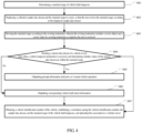
- FIG. 4 is a schematic flow diagram of implementing a vehicle diagnostic method according to another embodiment of the present application. The method is applied to a vehicle diagnostic device. As shown in FIG. 4 , because the implementations of step 401, step S404 and step S405 in this embodiment are respectively and completely the same as the implementations of step S101 to step S103 in the embodiment shown in FIG. 1 , details are not described herein again.
- the vehicle diagnostic method provided in this embodiment further includes the following steps:
- the revise object in the revising instruction includes a data identifier of a sample data stream to be revised, a maximum value of the sample data stream to be revised, and/or a minimum value of the sample data stream to be revised.
- the revise value includes a maximum value of a revised sample data stream and/or a minimum value of the revised sample data stream.
- a vehicle diagnostic device presents, to the user on a display interface, the collected sample data stream and the standard range that is obtained by executing a computer program processing procedure, and the user is allowed to revise the standard range, in other words, the maximum value and the minimum value of the sample data stream, and use the maximum value and the minimum value of the revise sample data stream as a standard range used for vehicle fault diagnosis and determining. In this way, the precision of the vehicle fault diagnosis may be further improved.
- the vehicle diagnostic method provided in this embodiment further includes:
- the vehicle identification number includes information such as a manufacturer, an age, a vehicle model, a vehicle body model and code, an engine code, and an assembly location of the vehicle.
- the correlation is sent to the website server in a form of one piece of data information, and is stored.
- another vehicle diagnostic device can obtain the sample data stream of the vehicle and the standard range for vehicle failure diagnosis from the website server, so that vehicle diagnosis is more intelligent, and the user experience is further improved.
- the vehicle diagnostic method provided in this embodiment since the user is allowed to revise the standard range of vehicle diagnosis, the reliability of the standard range is improved, and the precision of the vehicle diagnosis is further improved. Since the vehicle identification number of the vehicle, the sample data stream, and the standard range for vehicle failure diagnosis are uploaded to the website server, so that another vehicle diagnostic device can directly obtain the sample data stream of the vehicle and the standard range for vehicle failure diagnosis from the website server, and use the obtained sample data stream of the vehicle and the obtained standard range for vehicle failure diagnosis to perform vehicle diagnosis on another vehicle of a same vehicle type, thereby further improving an intelligence of the vehicle diagnosis, and improving a user experience.
- a specific implementation of the vehicle diagnostic method provided in the embodiments of the present application is described by taking a temperature data stream of an engine of a vehicle as an example, which is described in detail as follows:
- the standard range of the temperature data stream of the engine when the vehicle operates normally is determined, subsequently, the current temperature data stream of the vehicle collected in real time is compared with the standard range to determine whether a fault occurs in the vehicle, and a corresponding fault detection result is output, such that the precision of vehicle fault diagnosis may be improved.
- FIG. 5 is a schematic structural diagram of a vehicle diagnostic system according to an embodiment of the present application. The system is applied to a vehicle diagnostic device. For describing conveniently, only the part related to this embodiment is shown.
- a vehicle diagnostic system 5 provided in this embodiment includes:
- the standard acquisition unit 51 is particularly configured to: collect a sample data stream of the vehicle, count the maximum value and the minimum value of the sample data stream, and store the maximum value and the minimum value of the sample data stream as the standard range for vehicle failure diagnosis.
- the standard acquisition unit 51 is particularly configured to:
- the vehicle diagnosis unit 52 is particularly configured to:
- the vehicle diagnostic system 5 further comprises:
- the vehicle diagnostic system 5 comprises: a communications unit 56 configured to obtain a vehicle identification number of the vehicle, establish a correlation among the vehicle identification number, the sample data stream, and the standard range for vehicle failure diagnosis, and upload the correlation to a website server.
- the sample data stream of the vehicle is collected, the maximum value and the minimum value of the collected sample data stream are used as the standard range for vehicle failure diagnosis, subsequently, the current data stream of the vehicle collected in real time is compared with the standard range to determine whether a fault occurs in the vehicle, and a corresponding fault detection result is output, such that the precision of the vehicle fault diagnosis may be improved.
- sequence numbers of the steps in this embodiment do not represent an execution sequence.
- the execution sequence of the processes should be determined according to functions and internal logic.
- the sequence numbers should not constitute any limitation to an implementation process of this embodiment of the present application.
- FIG. 7 is a schematic structural diagram of a vehicle diagnostic device according to an embodiment of the present application.
- the vehicle diagnostic device in this embodiment comprises a processor 70, a memory 71, and a computer program 72 stored in the memory 71 and executable by the processor 70.
- the processor 70 is configured to execute the computer program 72 to implement functions of the various units in the system embodiment, such as functions of the modules 51-53 shown in FIG. 5 .
- the computer program 72 may be divided into one or more units, and the one or more units are stored in the memory 71 and are executed by the processor 70 so as to implement the present application.
- the one or more units may be a series of computer program instruction segments that can complete a particular function, and the instruction segments are used to describe an execution process of the computer program 72 in the device.
- the processor 70 executes the computer program 72, the processor 70 implements the steps in the method embodiment, such as the steps 101-103 shown in FIG. 1 .
- processor 70 executes the computer program 72
- the processor 70 implements the following steps of:
- the processor 70 when the processor 70 executes the computer program 72, the processor 70 may further implement the following steps of: collecting a sample data stream of the vehicle, counting the maximum value and the minimum value of the sample data stream, and storing the maximum value and the minimum value of the sample data stream as the standard range for vehicle failure diagnosis.
- processor 70 when the processor 70 is further configured to execute the computer program 72 to implement the following steps of:
- processor 70 when processor 70 is further configured to execute the computer program 72 to implement the following steps of:
- the processor 70 is further configured to execute the computer program 72 to implement the following steps of:
- the processor 70 is further configured to execute the computer program 72 to implement the following steps of: obtaining a vehicle identification number of the vehicle, establishing a correlation among the vehicle identification number, the sample data stream, and the standard range for vehicle failure diagnosis, and uploading the correlation to a website server.
- the vehicle diagnostic device 7 may include but is not limited to the processor 70 and the memory 71.
- FIG. 7 shows only an example of the vehicle diagnostic device 7 but does not limit the vehicle diagnostic device 7.
- the vehicle diagnostic device 7 may include more or fewer components than those shown in the figures, or some components may be combined, or the vehicle diagnostic device may include different components.
- the vehicle diagnostic device 7 may further include an input/output device, a network access device, a bus, and the like.
- the processor 70 may be a central processing unit (Central Processing Unit, CPU), or the processor may be another general purpose processor, a digital signal processor (Digital Signal Processor, DSP), an application specific integrated circuit (Application Specific Integrated Circuit, ASIC), a field-programmable gate array (Field-Programmable Gate Array, FPGA) or another programmable logic device, a discrete gate or transistor logic device, a discrete hardware component, or the like.
- the general purpose processor may be a microprocessor or the processor may be any normal processor, or the like.
- the memory 71 may be an internal storage unit of the vehicle diagnostic device 7, for example, a hard disk or a memory of the vehicle diagnostic device 7.
- the memory 71 may alternatively be an external storage device of the vehicle diagnostic device 7, for example, a plug-connected hard disk, a smart media card (Smart Media Card, SMC), a secure digital (Secure Digital, SD) card, or a flash card (Flash Card) disposed on the vehicle diagnostic device 7.
- the memory 71 may alternatively include both the internal storage unit and the external storage device of the vehicle diagnostic device 7.
- the memory 71 is configured to store the computer program and another program and data needed by the vehicle diagnostic device 7.
- the memory 71 may be further configured to temporarily store data that is output or that is to be output.
- the disclosed vehicle diagnostic method, vehicle diagnostic system and vehicle diagnostic device could be implemented in other ways.
- the vehicle diagnostic device described above are merely illustrative; for example, the division of the units is only a logical function division, and other division could be used in the actual implementation, for example, multiple units or components could be combined or integrated into another system, or some features may be ignored, or not performed.
- the coupling or direct coupling or communicating connection shown or discussed could be an indirect, or a communicating connection through some interfaces, devices or units, which could be electrical, mechanical, or otherwise.
- the units described as separate components could or could not be physically separate, the components shown as units could or could not be physical units, which may be located in one place, or may be distributed to multiple network elements. Parts or all of the elements could be selected according to the actual needs to achieve the object of the present embodiment.
- each of the embodiments of the present application may be integrated into a single processing unit, or exist individually and physically, or two or more than two units are integrated into one unit.
- the aforementioned integrated unit can either be achieved by hardware or be achieved in the form of software functional units.
- the integrated unit is achieved in the form of software functional units, and is sold or used as an independent product, it may be stored in a computer readable storage medium. Based on this understanding, a whole or part of flow process of implementing the method in the aforementioned embodiments of the present application can also be accomplished by using computer program to instruct relevant hardware. When the computer program is executed by the processor, the steps in the various method embodiments described above may be implemented.
- the computer program comprises computer program codes, which may be in the form of source code, object code, executable documents or some intermediate form, etc.
- the computer readable medium can include: any entity or device that can carry the computer program codes, recording medium, USB flash disk, mobile hard disk, hard disk, optical disk, computer storage device, ROM (Read-Only Memory), RAM (Random Access Memory), electrical carrier signal, telecommunication signal and software distribution medium, etc. It needs to be explained that, the contents contained in the computer readable medium may be added or reduced appropriately according to the requirement of legislation and patent practice in a judicial district, for example, in some judicial districts, according to legislation and patent practice, the computer readable medium doesn't include electrical carrier signal and telecommunication signal.
Landscapes
- Physics & Mathematics (AREA)
- General Physics & Mathematics (AREA)
- Engineering & Computer Science (AREA)
- Automation & Control Theory (AREA)
- Human Computer Interaction (AREA)
- Vehicle Cleaning, Maintenance, Repair, Refitting, And Outriggers (AREA)
- Testing And Monitoring For Control Systems (AREA)
Description
- The present application pertains to the technical field of vehicle diagnosis, and particularly to a vehicle diagnostic method, a vehicle diagnostic system, a vehicle diagnostic device, and a computer readable storage medium.
- Automotive data stream are data parameters exchanged between an electronic control unit and sensors and an actuator and read by dedicated diagnostic equipment through a diagnosis interface. The data stream recorded in the automotive electronic control unit really reflects working voltages and statuses of the sensors and the actuator, provides a basis for automotive fault diagnosis.
- Currently, when an automotive diagnosis device in a vehicle performs fault diagnosis on the vehicle, the automotive diagnosis device usually determines whether a fault occurs in the vehicle by comparing an automotive data stream collected in real time with a standard value range designated by diagnosis software. The used standard value range is an empirical value set by the diagnosis software, which results in an inaccurate detected vehicle fault diagnosis result.
- For example, a prior art document D1 (
CN1904776A ) discloses a self-learning judgment method for automobile decoder, comprising steps of: obtaining a code indicating an operating state of the vehicle testing system and performing decoding on the code to generate tested data of vehicle operating state; comparing the tested data of the vehicle operating state with the maximum value XH and the minimum value XL of standard value in the standard database of vehicle operating state, replacing the maximum value XH with the tested data when the tested data is greater than the maximum value XH in the standard data, replacing the minimum value XL with the tested data when the tested data is less than the minimum value XL in the standard data, or alternatively storing the tested data as the maximum and the minimum value of the standard value, if there is no corresponding standard data in the database. The self-learning judgment method for automobile decoder could be used to diagnose different kinds of cars, and improve working efficiency. Another prior art document D2 (US2011/196572A1 ) discloses generation of reference value for vehicle failure diagnosis in which data during normal driving is generated using travel data during the occurrence of a failure or the like, the travel data being accumulated into ordinary vehicles traveling in a city or other places on a daily basis. A failure diagnosis of a vehicle is performed by comparing a reference value with the time sequence electronic control unit (ECU) data of a plurality of driving parameters during the occurrence of a failure, the data being stored into a storage device in the ECU of the vehicle when a failure of the vehicle has occurred. The time sequence ECU data obtained from a large number of vehicles are sequentially accumulated and stored and the numerical vectors of the accumulated time sequence ECU data are generated. The numerical vectors are clustered and classified into a plurality of clusters according to the characteristics. In each of the plurality of clusters, a range of high occurrence rate values is obtained for the values of the respective driving parameters. The obtained range of high occurrence rate values is then stored as a range of the normal values of the driving parameters, and the range of the normal values is set as the reference value for a failure diagnosis. - In view of this, the present application provides a vehicle diagnostic method, a vehicle diagnostic system, and device, and a computer readable storage medium, which aims at resolving a problem that a detected vehicle fault diagnosis result is imprecise due to the fact that a standard value range used by an existing vehicle diagnostic device is an empirical value set by diagnosis software.
- In a first aspect, the present application provides a vehicle diagnostic method comprising steps of: determining a standard range for vehicle failure diagnosis; reading a current data stream of a vehicle in real time when a vehicle diagnosis instruction is received, and determining whether values of the current data stream are within a standard range; and outputting prompt information indicative of normal vehicle operation if the values of the current data stream are within the standard range; or alternatively outputting corresponding vehicle failure alarm information if the values of the current data stream are beyond the standard range;
- the step of determining a standard range for vehicle failure diagnosis particularly includes: collecting a sample data stream of the vehicle, counting the maximum value and the minimum value of the sample data stream, and storing the maximum value and the minimum value of the sample data stream as the standard range for vehicle failure diagnosis;
- the step of collecting a sample data stream of the vehicle, counting the maximum value and the minimum value of the sample data stream, and storing the maximum value and the minimum value of the sample data stream as the standard range for vehicle failure diagnosis comprises: collecting, according to a preset period, an automotive data stream when the vehicle is operated in a normal state; determining whether the automotive data stream collected within the current period includes a data identifier and a data unit; deleting the automotive data stream if the automotive data stream does not include the data identifier or the data unit; or
- determining whether there is sample data stream matching the data identifier in the collected sample data stream if the automotive data stream includes the data identifier and the data unit; and using the maximum value and the minimum value of the automotive data stream to revise the maximum value and the minimum value of the matched sample data stream respectively if there is sample data stream matching the data identifier; or collecting and using the automotive data stream as a sample data stream if there is no sample data stream matching the data identifier;
- the method further comprises: obtaining a vehicle identification number of the vehicle, establishing an correlation between the vehicle identification number, the sample data stream, and the standard range for vehicle failure diagnosis, and sending the correlation to a website server in a form of one piece of data information.
- In a second aspect, the present application provides a vehicle diagnostic system, comprising: a standard acquisition unit configured to determine a standard range for vehicle failure diagnosis; a vehicle diagnosis unit configured to read a current data stream of a vehicle in real time when a vehicle diagnosis instruction is received, and determine whether values of the current data stream are within the standard range; and a diagnosis result output unit configured to: output prompt information indicative of normal vehicle operation if the values of the current data stream are within the standard range; or output corresponding vehicle failure alarm information if the values of the current data stream are beyond the standard range;
- the standard acquisition unit is particularly configured to collect a sample data stream of the vehicle, count the maximum value and the minimum value of the sample data stream, and store the maximum value and the minimum value of the sample data stream as the standard range for vehicle failure diagnosis;
- the standard acquisition unit is particularly configured to collect, according to a preset period, an automotive data stream when the vehicle is operated in a normal state; determine whether the automotive data stream collected within the current period includes a data identifier and a data unit;
- delete the automotive data stream if the automotive data stream does not include the data identifier or the data unit; or determine whether there is sample data stream matching the data identifier in the collected sample data stream if the automotive data stream includes the data identifier and the data unit; and if there is sample data stream matching the data identifier, use the maximum value and the minimum value of the automotive data stream to revise the maximum value and the minimum value of the matched sample data stream respectively; or if there is no sample data stream matching the data identifier, collect and use the automotive data stream as a sample data stream;
- the vehicle diagnostic system further comprises a communication unit configured to:
obtain a vehicle identification number of the vehicle, establish a correlation between the vehicle identification number, the sample data stream, and the standard range for vehicle failure diagnosis, and send the correlation to a website server in a form of one piece of data information. - Based on the aforementioned technical solution, the system further comprises: a revising and displaying unit configured to present the collected sample data stream and the standard range for vehicle failure diagnosis to a user on a display interface of a vehicle diagnostic device to allow the user to revise the standard range for vehicle failure diagnosis by revising the maximum value and the minimum value of the sample data stream.
- In a third aspect, the present application provides a vehicle diagnostic device, comprising a memory, a processor, a vehicle diagnostic system in the second aspect, and a computer program stored in the memory and executable by the processor, wherein the processor is configured to execute the computer program to implement the steps of the method in the first aspect.
- A fourth aspect of the present application provides a computer readable storage medium storing a computer program comprising instructions which, when executed by a processor, cause the processor to carry out the steps of the method in the first aspect.
- In the present application, the sample data stream of the vehicle is collected, the maximum value and the minimum value of the collected sample data stream are used as the standard range for vehicle failure diagnosis, subsequently, the current data stream of the vehicle collected in real time is compared with the standard range to determine whether a fault occurs in the vehicle, and a corresponding fault detection result is output, such that the precision of the vehicle fault diagnosis may be improved.
- In order to describe the technical solutions in the embodiments of the present application more clearly, the following briefly describes the accompanying drawings required for describing the embodiments or the prior art.
-
FIG. 1 illustrates a schematic flow diagram of implementing a vehicle diagnostic method according to an embodiment of the present application; -
FIG. 2 illustrates a schematic flow diagram of a specific implementation ofstep S 101 in the vehicle diagnostic method according to an embodiment of the present application; -
FIG. 3 illustrates a schematic flow diagram of a specific implementation of step S102 in the vehicle diagnostic method according to an embodiment of the present application; -
FIG. 4 illustrates a schematic flow diagram of implementing a vehicle diagnostic method according to another embodiment of the present application; -
FIG. 5 illustrates a schematic structural diagram of a vehicle diagnostic system according to an embodiment of the present application; -
FIG. 6 illustrates a schematic structural diagram of a vehicle diagnostic system according to another embodiment of the present application; and -
FIG. 7 illustrates a schematic structural diagram of a vehicle diagnostic device according to an embodiment of the present application. - In the following description, for description rather than limitation, specific details such as a particular system structure and a technology are provided for thorough understanding of the embodiments of the present application. To describe the technical solutions of the present application, the following gives a description by using specific embodiments.
-
FIG. 1 is a schematic flow diagram of implementing a vehicle diagnostic method according to an embodiment of the present application. The method is applied to a vehicle diagnostic device. As shown inFIG. 1 , an implementation procedure of the method is described in detail as follows:
Step 101, determining a standard range for vehicle failure diagnosis. - Wherein, the step of determining a standard range for vehicle failure diagnosis particularly includes: collecting a sample data stream of the vehicle, counting the maximum value and the minimum value of the sample data stream, and storing the maximum value and the minimum value of the sample data stream as the standard range for vehicle failure diagnosis.
- Since data stream comparison is meaningful for comparison between data of a same vehicle model, a same vehicle series, and a same vehicle system. Therefore, to accurately select a correct sample data stream subsequently, in this embodiment, a vehicle identification number (Vehicle Identification Number, VIN) is added to the collected sample data stream of the vehicle. The VIN includes 17 characters, and therefore, is commonly referred to as a 17-bit code. The VIN includes information such as a manufacturer, an age, a vehicle model, a vehicle body model and code, an engine code, and an assembly location of the vehicle. In addition, to distinguish between different types of data streams of a same vehicle, various collected sample data streams further carry data identifiers used to mark data types.
- Preferably,
FIG. 2 illustrates a specific implementation procedure of step S101. As shown inFIG. 2 , step S101 particularly includes the following steps: - Step 201, collecting, according to a preset period, an automotive data stream when a vehicle is operated in a normal state.
-
Step 202, determining whether the automotive data stream collected within the current period includes a data identifier and a data unit; and performingstep 203 if the automotive data stream does not include the data identifier or the data unit; or performingstep 204 if the automotive data stream includes the data identifier and the data unit. -
Step 203, deleting the automotive data stream. -
Step 204, determining whether there is sample data stream matching the data identifier in the collected sample data stream; and if there is sample data stream matching the data identifier, performingstep 205; or performingstep 206 if the sample data stream matching the data identifier does not exist. -
Step 205, using the maximum value and the minimum value of the automotive data stream to revise the maximum value and the minimum value of the matched sample data stream respectively. -
Step 206, collecting and using the automotive data stream as a sample data stream. - During collection of the sample data stream of the vehicle, it needs to be ensured that the vehicle is in a normal operation state, and a collected data stream of the vehicle needs to carry a data identifier and a data unit. When an operation state of the vehicle is abnormal within a particular data stream collection period or a data stream collected within the particular data stream collection period does not include a data identifier or a data unit, the data stream collected within the current period is directly deleted, and is not collected, so that the reliability of the collected sample data stream may be ensured.
- When the sample data stream matching the data identifier carried in the currently collected automotive data stream does not exist in the collected sample data stream, it indicates that it is the first time to collect a sample data stream of the automotive data stream of this type. In this case, the currently collected automotive data stream is collected and used as an initialized sample data stream corresponding to this type.
- When the sample data stream matching the data identifier carried in the currently collected automotive data stream exists in the collected sample data stream, it indicates that it is not the first time to collect a sample data stream of the automotive data stream of this type. In this case, the currently collected automotive data stream is used to revise the collected corresponding sample data stream.
- The step of using the maximum value and the minimum value of the automotive data stream to revise the maximum value and the minimum value of the matched sample data stream respectively particularly includes:
respectively comparing the maximum value and the minimum value of the currently collected automotive data stream with the maximum value and the minimum value of the sample data stream; modifying the maximum value of the sample data stream into the maximum value of the automotive data stream if the maximum value of the automotive data stream is greater than the maximum value of the sample data stream; and modifying the minimum value of the sample data stream into the minimum value of the automotive data stream if the minimum value of the automotive data stream is less than the minimum value of the sample data stream. - In this embodiment, a sample data stream of the vehicle may be collected once every a time period, and the standard range used for vehicle fault determining of the vehicle may be revised each time after the sample data stream of the vehicle is collected, thereby ensuring the reliability of a subsequent vehicle fault determining and detection result.
-
Step 102, reading a current data stream of the vehicle in real time when a vehicle diagnosis instruction is received, and determining whether values of the current data stream are within the standard range; and performingstep 103 if the values of the current data stream are within the standard range; or performingstep 104 if the values of the current data stream are beyond the standard range. - Preferably,
FIG. 3 illustrates a specific implementation procedure ofstep 102. As shown inFIG. 2 , step 102 particularly includes: -
Step 301, reading the current data stream of the vehicle in real time when the vehicle diagnosis instruction is received, and determining whether the current data stream includes a data identifier and a data unit; and performingstep 302 if the current data stream does not include the data identifier or the data unit; or performingstep 303 if the current data stream includes the data identifier and the data unit. -
Step 302, deleting the current data stream. -
Step 303, searching the collected sample data stream for a sample data stream matching the data identifier of the current data stream. -
Step 304, determining whether the maximum value and the minimum value of the current data stream are within a range between the maximum value and the minimum value of the matched sample data stream. - In this embodiment, considering that a data stream that does not include a data identifier or a data unit cannot be used for precise comparison, a currently collected data stream that does not include a data identifier or a data unit is filtered out and is not used for comparison.
- In this embodiment, if the current data stream read in real time includes the data identifier and the data unit, during real-time refreshing and comparison, metric-inch conversion is performed for each data stream, to obtain the maximum value and the minimum value of the current data stream in a metric/inch mode, and in addition, metric-inch conversion is performed for the matched sample data stream, to obtain the maximum value and the minimum value of the sample data stream in the current metric/inch mode. Then, the maximum value and the minimum value of the current data stream in the current metric/inch mode are respectively compared with the maximum value and the minimum value of the matched sample data stream in the current metric/inch mode, to determine whether the maximum value and the minimum value of the current data stream are within the standard range. In this way, collected sample data stream may be compared with a real-time data stream in different languages and different metric/inch modes.
-
Step 103, outputting prompt information indicative of normal vehicle operation. - In this embodiment, when the maximum value and the minimum value of the current data stream are within the standard range, it indicates that the vehicle operates normally, and in this case, the prompt information indicative of normal vehicle operation is displayed on a vehicle diagnosis display interface.
-
Step 104, outputting corresponding vehicle failure alarm information. - In this embodiment, when the maximum value and the minimum value of the current data stream exceed the standard range, it indicates that a fault occurs in the vehicle, and in this case, a fault type of the vehicle is determined according to the data identifier of the current data stream with reference to specific values by which the maximum value and the minimum value exceed the standard range, and preset failure alarm information corresponding to the fault type is output. For example, marks of different warning colors may be displayed and/or corresponding fault type voice prompts are given, to send vehicle failure alarm prompts to the user.
- As may be learned from the above, in the vehicle diagnostic method provided in this embodiment, the sample data stream of the vehicle is collected, the maximum value and the minimum value of the collected sample data stream are used as the standard range for vehicle failure diagnosis, subsequently, the current data stream of the vehicle collected in real time is compared with the standard range to determine whether a fault occurs in the vehicle, and a corresponding fault detection result is output, thereby improving the precision of the vehicle fault diagnosis.
-
FIG. 4 is a schematic flow diagram of implementing a vehicle diagnostic method according to another embodiment of the present application. The method is applied to a vehicle diagnostic device. As shown inFIG. 4 , because the implementations ofstep 401, step S404 and step S405 in this embodiment are respectively and completely the same as the implementations of step S101 to step S103 in the embodiment shown inFIG. 1 , details are not described herein again. Compared with the foregoing embodiment, the vehicle diagnostic method provided in this embodiment further includes the following steps: - Step S402, displaying collected sample data stream and the standard range to a user, so that the user revises the standard range according to the displayed sample data stream.
-
Step 403, if a revising instruction input by the user is received, revising the standard range according to the revising instruction, wherein the revising instruction includes a revise object and a revise value. - In this embodiment, the revise object in the revising instruction includes a data identifier of a sample data stream to be revised, a maximum value of the sample data stream to be revised, and/or a minimum value of the sample data stream to be revised. The revise value includes a maximum value of a revised sample data stream and/or a minimum value of the revised sample data stream.
- In this embodiment, a vehicle diagnostic device presents, to the user on a display interface, the collected sample data stream and the standard range that is obtained by executing a computer program processing procedure, and the user is allowed to revise the standard range, in other words, the maximum value and the minimum value of the sample data stream, and use the maximum value and the minimum value of the revise sample data stream as a standard range used for vehicle fault diagnosis and determining. In this way, the precision of the vehicle fault diagnosis may be further improved.
- Preferably, compared with the previous embodiment, the vehicle diagnostic method provided in this embodiment further includes:
-
step 404, reading a current data stream of a vehicle in real time when a vehicle diagnosis instruction is received, and determining whether values of the current data stream are within the standard range; if the values of the current data stream are within the standard range, executingstep 405, if the values of the current data stream are beyond the standard range, executingstep 406; -
step 405, outputting prompt information indicative of normal vehicle operation; -
step 406, outputting corresponding vehicle failure alarm information; -
step 407, obtaining a vehicle identification number of the vehicle, establishing an correlation between the vehicle identification number, the sample data stream, and the standard range for vehicle failure diagnosis, and uploading the correlation to a website server. - In this embodiment, the vehicle identification number includes information such as a manufacturer, an age, a vehicle model, a vehicle body model and code, an engine code, and an assembly location of the vehicle. After the correlation is established between the vehicle identification number, the sample data stream, and the standard range for vehicle failure diagnosis, the correlation is sent to the website server in a form of one piece of data information, and is stored. In this way, another vehicle diagnostic device can obtain the sample data stream of the vehicle and the standard range for vehicle failure diagnosis from the website server, so that vehicle diagnosis is more intelligent, and the user experience is further improved.
- As may be learned from the above, compared with the previous embodiment, in the vehicle diagnostic method provided in this embodiment, since the user is allowed to revise the standard range of vehicle diagnosis, the reliability of the standard range is improved, and the precision of the vehicle diagnosis is further improved. Since the vehicle identification number of the vehicle, the sample data stream, and the standard range for vehicle failure diagnosis are uploaded to the website server, so that another vehicle diagnostic device can directly obtain the sample data stream of the vehicle and the standard range for vehicle failure diagnosis from the website server, and use the obtained sample data stream of the vehicle and the obtained standard range for vehicle failure diagnosis to perform vehicle diagnosis on another vehicle of a same vehicle type, thereby further improving an intelligence of the vehicle diagnosis, and improving a user experience.
- As an example of specific implementation, a specific implementation of the vehicle diagnostic method provided in the embodiments of the present application is described by taking a temperature data stream of an engine of a vehicle as an example, which is described in detail as follows:
- determining a standard range of a temperature data stream of the engine when the vehicle operates normally;
- reading a current temperature data stream of the engine of the vehicle in real time when a vehicle diagnosis instruction is received, and determining whether values of the current temperature data stream are within the standard range; and
- outputting prompt information indicative of normal vehicle operation if the values of the current temperature data stream are within the standard range; or
- outputting corresponding vehicle failure alarm information if the values of the current temperature data stream are beyond the standard range.
- It should be noted that because specific implementations of the steps in this implementation example are completely the same as the implementations of
step 101 to step 104 in the embodiment shown inFIG. 1 , details are not repeatedly described herein. - In this implementation example, the standard range of the temperature data stream of the engine when the vehicle operates normally is determined, subsequently, the current temperature data stream of the vehicle collected in real time is compared with the standard range to determine whether a fault occurs in the vehicle, and a corresponding fault detection result is output, such that the precision of vehicle fault diagnosis may be improved.
-
FIG. 5 is a schematic structural diagram of a vehicle diagnostic system according to an embodiment of the present application. The system is applied to a vehicle diagnostic device. For describing conveniently, only the part related to this embodiment is shown. - As shown in
FIG. 5 , a vehiclediagnostic system 5 provided in this embodiment includes: - a
standard acquisition unit 51 configured to determine a standard range for vehicle failure diagnosis; - a
vehicle diagnosis unit 52 configured to read a current data stream of a vehicle in real time when a vehicle diagnosis instruction is received, and determine whether values of the current data stream are within the standard range; and - a diagnostic
result output unit 53 configured to:- output prompt information indicative of normal vehicle operation if the values of the current data stream are within the standard range; or
- output corresponding vehicle failure alarm information if the values of the current data stream are beyond the standard range.
- In one embodiment, the
standard acquisition unit 51 is particularly configured to:
collect a sample data stream of the vehicle, count the maximum value and the minimum value of the sample data stream, and store the maximum value and the minimum value of the sample data stream as the standard range for vehicle failure diagnosis. - In one embodiment, the
standard acquisition unit 51 is particularly configured to: - collect a automotive data stream according to a preset period, when the vehicle is operated in a normal state;
- determine whether the automotive data stream collected within the current period includes a data identifier and a data unit;
- delete the automotive data stream if the automotive data stream does not include the data identifier or the data unit; or
- determine whether there is sample data stream matching the data identifier in the collected sample data stream if the automotive data stream includes the data identifier and the data unit; and
- use the maximum value and the minimum value of the automotive data stream to revise the maximum value and the minimum value of the matched sample data stream respectively if there is sample data stream matching the data identifier; or
- collect and use the automotive data stream as a sample data stream if there is no sample data stream matching the data identifier.
- In one embodiment, the
vehicle diagnosis unit 52 is particularly configured to: - read the current data stream of the vehicle in real time when the vehicle diagnosis instruction is received, and determine whether the current data stream includes a data identifier and a data unit;
- delete the current data stream if the current data stream does not include the data identifier or the data unit; or
- search the collected sample data stream for a sample data stream matching the data identifier of the current data stream if the current data stream includes the data identifier and the data unit; and
- determine whether the maximum value and the minimum value of the current data stream are within a range between the maximum value and the minimum value of the matched sample data stream.
- In one embodiment, as shown in
FIG. 6 , in another embodiment, the vehiclediagnostic system 5 further comprises: - a revising and displaying
unit 54 configured to display the collected sample data stream and the standard range to a user, so that the user revises the standard range according to the displayed sample data stream; and - a revising and
processing unit 55 configured to: revise the standard range according to the revising instruction if a revising instruction input by the user is received, where the revising instruction includes a revise object and a revise value. - In one embodiment, the vehicle
diagnostic system 5 comprises:
acommunications unit 56 configured to obtain a vehicle identification number of the vehicle, establish a correlation among the vehicle identification number, the sample data stream, and the standard range for vehicle failure diagnosis, and upload the correlation to a website server. - It should be noted that, since the units of the system provided in this embodiment of the present application are based on a same concept as the method embodiment of the present application, technical effects thereof are the same as those of the method embodiment of the present application. Regarding concrete content, reference may be made to relevant descriptions in the method embodiment of the present application, and it is not repeatedly described herein.
- Therefore, it may be seen that, in the vehicle diagnostic system provided in this embodiment, the sample data stream of the vehicle is collected, the maximum value and the minimum value of the collected sample data stream are used as the standard range for vehicle failure diagnosis, subsequently, the current data stream of the vehicle collected in real time is compared with the standard range to determine whether a fault occurs in the vehicle, and a corresponding fault detection result is output, such that the precision of the vehicle fault diagnosis may be improved.
- It should be understood that sequence numbers of the steps in this embodiment do not represent an execution sequence. The execution sequence of the processes should be determined according to functions and internal logic. The sequence numbers should not constitute any limitation to an implementation process of this embodiment of the present application.
-
FIG. 7 is a schematic structural diagram of a vehicle diagnostic device according to an embodiment of the present application. As shown inFIG. 7 , the vehicle diagnostic device in this embodiment comprises aprocessor 70, amemory 71, and acomputer program 72 stored in thememory 71 and executable by theprocessor 70. Theprocessor 70 is configured to execute thecomputer program 72 to implement functions of the various units in the system embodiment, such as functions of the modules 51-53 shown inFIG. 5 . Thecomputer program 72 may be divided into one or more units, and the one or more units are stored in thememory 71 and are executed by theprocessor 70 so as to implement the present application. The one or more units may be a series of computer program instruction segments that can complete a particular function, and the instruction segments are used to describe an execution process of thecomputer program 72 in the device. Alternatively, when theprocessor 70 executes thecomputer program 72, theprocessor 70 implements the steps in the method embodiment, such as the steps 101-103 shown inFIG. 1 . - For example, when the
processor 70 executes thecomputer program 72, theprocessor 70 implements the following steps of: - determining a standard range for vehicle failure diagnosis;
- reading a current data stream of a vehicle in real time when a vehicle diagnosis instruction is received, and determining whether values of the current data stream are within the standard range; and
- outputting prompt information indicative of normal vehicle operation if the values of the current data stream are within the standard range; or
- outputting corresponding vehicle failure alarm information if the values of the current data stream are beyond the standard range.
- In one embodiment, when the
processor 70 executes thecomputer program 72, theprocessor 70 may further implement the following steps of:
collecting a sample data stream of the vehicle, counting the maximum value and the minimum value of the sample data stream, and storing the maximum value and the minimum value of the sample data stream as the standard range for vehicle failure diagnosis. - In one embodiment, when the
processor 70 is further configured to execute thecomputer program 72 to implement the following steps of: - collecting an automotive data stream when the vehicle is operated in a normal state according to a preset period;
- determining whether the automotive data stream collected within the current period includes a data identifier and a data unit;
- deleting the automotive data stream if the automotive data stream does not include the data identifier or the data unit; or
- determining whether a sample data stream matching the data identifier exists in the collected sample data stream if the automotive data stream includes the data identifier and the data unit; and
- using the maximum value and the minimum value of the automotive data stream to revise the maximum value and the minimum value of the matched sample data stream respectively if there is sample data stream matching the data identifier; or
- collecting and using the automotive data stream as a sample data stream if there is no sample data stream matching the data identifier.
- In one embodiment, when
processor 70 is further configured to execute thecomputer program 72 to implement the following steps of: - displaying the collected sample data stream and the standard range to a user, so that the user revises the standard range according to the displayed sample data stream; and
- revising the standard range according to the revising instruction if a revising instruction input by the user is received, wherein the revising instruction includes a revise object and a revise value.
- In one embodiment, the
processor 70 is further configured to execute thecomputer program 72 to implement the following steps of: - reading the current data stream of the vehicle in real time when the vehicle diagnosis instruction is received, and determining whether the current data stream includes a data identifier and a data unit;
- deleting the current data stream if the current data stream does not include the data identifier or the data unit; or
- searching the collected sample data stream for a sample data stream matching the data identifier of the current data stream if the current data stream includes the data identifier and the data unit; and
- determining whether the maximum value and the minimum value of the current data stream are within a range between the maximum value and the minimum value of the matched sample data stream.
- In one embodiment, the
processor 70 is further configured to execute thecomputer program 72 to implement the following steps of:
obtaining a vehicle identification number of the vehicle, establishing a correlation among the vehicle identification number, the sample data stream, and the standard range for vehicle failure diagnosis, and uploading the correlation to a website server. - The vehicle
diagnostic device 7 may include but is not limited to theprocessor 70 and thememory 71. The one of ordinary skill in the art may understand thatFIG. 7 shows only an example of the vehiclediagnostic device 7 but does not limit the vehiclediagnostic device 7. The vehiclediagnostic device 7 may include more or fewer components than those shown in the figures, or some components may be combined, or the vehicle diagnostic device may include different components. For example, the vehiclediagnostic device 7 may further include an input/output device, a network access device, a bus, and the like. - The
processor 70 may be a central processing unit (Central Processing Unit, CPU), or the processor may be another general purpose processor, a digital signal processor (Digital Signal Processor, DSP), an application specific integrated circuit (Application Specific Integrated Circuit, ASIC), a field-programmable gate array (Field-Programmable Gate Array, FPGA) or another programmable logic device, a discrete gate or transistor logic device, a discrete hardware component, or the like. The general purpose processor may be a microprocessor or the processor may be any normal processor, or the like. - The
memory 71 may be an internal storage unit of the vehiclediagnostic device 7, for example, a hard disk or a memory of the vehiclediagnostic device 7. Thememory 71 may alternatively be an external storage device of the vehiclediagnostic device 7, for example, a plug-connected hard disk, a smart media card (Smart Media Card, SMC), a secure digital (Secure Digital, SD) card, or a flash card (Flash Card) disposed on the vehiclediagnostic device 7. Further, thememory 71 may alternatively include both the internal storage unit and the external storage device of the vehiclediagnostic device 7. Thememory 71 is configured to store the computer program and another program and data needed by the vehiclediagnostic device 7. Thememory 71 may be further configured to temporarily store data that is output or that is to be output. - It may be clearly understood by one or ordinary skill in the art that, for describing conveniently and concisely, dividing of the aforementioned various functional units, functional modules is exemplified merely, in an actual application, the aforementioned functions may be assigned to different functional units and functional modules to be accomplished, that is, an inner structure of a data synchronizing device is divided into functional units or modules so as to accomplish the whole or a part of functionalities described above. The various functional units, modules in the embodiments may be integrated into a processing unit, or each of the units exists independently and physically, or two or more than two of the units are integrated into a single unit. The aforementioned integrated unit can by either realized in the form of hardware or in the form of software functional units. In addition, specific names of the various functional units and modules are only used for distinguishing from each other conveniently, but not intended to limit the protection scope of the present application. Regarding a specific working process of the units and modules in the aforementioned device, please refer to a corresponding process in the aforementioned method embodiments, it is not repeatedly described herein.
- In the foregoing embodiments, descriptions of the embodiments have emphases, regarding a part that is not described or recorded in an embodiment, reference may be to related descriptions of other embodiments.
- One of ordinary skill in the art may be aware that the units and algorithm steps in the examples described with reference to the embodiments disclosed in this specification may be implemented by electronic hardware or a combination of computer software and electronic hardware. Whether the functions are performed by hardware or software depends on particular applications and design constraint conditions of the technical solutions. The one of ordinary skill in the art may use different methods to implement the described functions for particular applications, however, the implementation should not be considered as going beyond the scope of the present application.
- It should be understood that, in the embodiments of the present application, the disclosed vehicle diagnostic method, vehicle diagnostic system and vehicle diagnostic device could be implemented in other ways. For example, the vehicle diagnostic device described above are merely illustrative; for example, the division of the units is only a logical function division, and other division could be used in the actual implementation, for example, multiple units or components could be combined or integrated into another system, or some features may be ignored, or not performed. In another aspect, the coupling or direct coupling or communicating connection shown or discussed could be an indirect, or a communicating connection through some interfaces, devices or units, which could be electrical, mechanical, or otherwise.
- The units described as separate components could or could not be physically separate, the components shown as units could or could not be physical units, which may be located in one place, or may be distributed to multiple network elements. Parts or all of the elements could be selected according to the actual needs to achieve the object of the present embodiment.
- In addition, the various functional units in each of the embodiments of the present application may be integrated into a single processing unit, or exist individually and physically, or two or more than two units are integrated into one unit. The aforementioned integrated unit can either be achieved by hardware or be achieved in the form of software functional units.
- If the integrated unit is achieved in the form of software functional units, and is sold or used as an independent product, it may be stored in a computer readable storage medium. Based on this understanding, a whole or part of flow process of implementing the method in the aforementioned embodiments of the present application can also be accomplished by using computer program to instruct relevant hardware. When the computer program is executed by the processor, the steps in the various method embodiments described above may be implemented. Wherein, the computer program comprises computer program codes, which may be in the form of source code, object code, executable documents or some intermediate form, etc. The computer readable medium can include: any entity or device that can carry the computer program codes, recording medium, USB flash disk, mobile hard disk, hard disk, optical disk, computer storage device, ROM (Read-Only Memory), RAM (Random Access Memory), electrical carrier signal, telecommunication signal and software distribution medium, etc. It needs to be explained that, the contents contained in the computer readable medium may be added or reduced appropriately according to the requirement of legislation and patent practice in a judicial district, for example, in some judicial districts, according to legislation and patent practice, the computer readable medium doesn't include electrical carrier signal and telecommunication signal.
Claims (4)
- A vehicle diagnostic method for a a vehicle diagnostic device, comprising:determining a standard range for vehicle failure diagnosis;reading a current data stream of a vehicle in real time when a vehicle diagnosis instruction is received, and determining whether values of the current data stream are within the standard range; andoutputting prompt information indicative of normal vehicle operation if the values of the current data stream are within the standard range, or outputting corresponding vehicle failure alarm information if the values of the current data stream are beyond the standard range;characterized in that,the step of determining a standard range for vehicle failure diagnosis particularly comprises: collecting a sample data stream of the vehicle, counting the maximum value and the minimum value of the sample data stream, and storing the maximum value and the minimum value of the sample data stream as the standard range for vehicle failure diagnosis; whereinthe step of collecting a sample data stream of the vehicle, counting the maximum value and the minimum value of the sample data stream, and storing the maximum value and the minimum value of the sample data stream as the standard range for vehicle failure diagnosis comprises:collecting an automotive data stream according to a preset period when the vehicle is operated in a normal state;determining whether the automotive data stream collected within the current period comprises a data identifier and a data unit;deleting the automotive data stream, if the automotive data stream does not comprise the data identifier or the data unit; ordetermining whether there is sample data stream matching the data identifier in the collected sample data stream, if the automotive data stream comprises the data identifier and the data unit; andusing the maximum value and the minimum value of the automotive data stream to revise the maximum value and the minimum value of the matched sample data stream respectively, if there is collected sample data stream matching the data identifier;collecting and using the automotive data stream as a sample data stream, if there is no collected sample data stream matching the data identifier;the method further comprises:
obtaining a vehicle identification number of the vehicle, establishing a correlation between the vehicle identification number, the sample data stream, and the standard range for vehicle failure diagnosis, and sending the correlation to a website server in a form of one piece of data information. - A vehicle diagnostic system (5), comprising:a standard acquisition unit (51) configured to determine a standard range for vehicle failure diagnosis;a vehicle diagnosis unit (52) configured to read a current data stream of a vehicle in real time when a vehicle diagnosis instruction is received, and determine whether values of the current data stream are within the standard range for vehicle failure diagnosis; anda diagnostic result output unit (53) configured to:output prompt information indicative of normal vehicle operation, if the values of the current data stream are within the standard range; or alternatively output corresponding vehicle fault alarm information, if the values of the current data stream are beyond the standard range;characterized in that,the standard acquisition unit (51) is particularly configured to:collect a sample data stream of the vehicle, count the maximum value and the minimum value of the sample data stream, and store the maximum value and the minimum value of the sample data stream as the standard range for vehicle failure diagnosis;the standard acquisition unit (51) is particularly configured to:collect an automotive data stream according to a preset period when the vehicle is operated in a normal state;determine whether the automotive data stream collected within the current period comprises a data identifier and a data unit;delete the automotive data stream, if the automotive data stream does not comprise the data identifier or the data unit; ordetermine whether there is sample data stream matching the data identifier in the collected sample data stream, if the automotive data stream comprises the data identifier and the data unit; anduse the maximum value and the minimum value of the automotive data stream to revise the maximum value and the minimum value of the matched sample data stream respectively, if there is sample data stream matching the data identifier; orcollect and use the automotive data stream as a sample data stream, if there is no sample data stream matching the data identifier;the vehicle diagnostic system (5) further comprises a communication unit (56) configured to:
obtain a vehicle identification number of the vehicle, establish a correlation between the vehicle identification number, the sample data stream, and the standard range for vehicle failure diagnosis, and send the correlation to a website server in a form of one piece of data information. - A vehicle diagnostic device (7), comprising a memory (71), a processor (70), a vehicle diagnostic system according to claim 2, and a computer program (72) stored in the memory (71) and executable by the processor (70), characterized in that, the processor (70) is configured to execute the computer program (72) to implement the steps of the method according to claim 1.
- A computer readable storage medium storing a computer program comprising instructions which, when executed by a processor, cause the processor to carry out the steps of the method according to claim 1.
Applications Claiming Priority (1)
| Application Number | Priority Date | Filing Date | Title |
|---|---|---|---|
| PCT/CN2018/084447 WO2019205017A1 (en) | 2018-04-25 | 2018-04-25 | Method, system, device, and computer readable storage medium for diagnosing vehicle |
Publications (3)
| Publication Number | Publication Date |
|---|---|
| EP3584658A1 EP3584658A1 (en) | 2019-12-25 |
| EP3584658A4 EP3584658A4 (en) | 2020-07-08 |
| EP3584658B1 true EP3584658B1 (en) | 2024-06-05 |
Family
ID=63841387
Family Applications (1)
| Application Number | Title | Priority Date | Filing Date |
|---|---|---|---|
| EP18839662.6A Active EP3584658B1 (en) | 2018-04-25 | 2018-04-25 | Method, system, device, and computer readable storage medium for diagnosing vehicle |
Country Status (4)
| Country | Link |
|---|---|
| US (1) | US11158143B2 (en) |
| EP (1) | EP3584658B1 (en) |
| CN (1) | CN108700875A (en) |
| WO (1) | WO2019205017A1 (en) |
Families Citing this family (27)
| Publication number | Priority date | Publication date | Assignee | Title |
|---|---|---|---|---|
| CN108628279B (en) * | 2017-03-21 | 2020-04-03 | 北京爱德盛业科技有限公司 | Analysis method for abnormal data flow of automobile based on cloud computing |
| CN108829088B (en) * | 2018-07-20 | 2021-11-05 | 深圳市道通科技股份有限公司 | Automobile diagnosis method and device and storage medium |
| CN109739838A (en) * | 2018-12-06 | 2019-05-10 | 中科恒运股份有限公司 | Abnormal data processing method and device |
| CN110045712B (en) * | 2019-03-06 | 2020-10-16 | 吉利汽车研究院(宁波)有限公司 | Controller fault processing method and device and terminal |
| CN112802227B (en) * | 2019-11-14 | 2023-11-21 | 北京车和家信息技术有限公司 | Vehicle ADAS driving data collection method, device, human-computer interaction device and vehicle |
| CN110909522B (en) * | 2019-11-22 | 2023-10-20 | 深圳市元征科技股份有限公司 | Data processing method and device, electronic equipment and medium |
| CN111260822B (en) * | 2019-12-31 | 2022-07-26 | 杭州安脉盛智能技术有限公司 | Rail transit vehicle health state analysis method and terminal based on big data |
| CN112199145A (en) * | 2020-10-10 | 2021-01-08 | 上海星融汽车科技有限公司 | Intelligent diagnosis method, system and diagnosis equipment for vehicle |
| CN112254983A (en) * | 2020-10-16 | 2021-01-22 | 中国第一汽车股份有限公司 | Vehicle detection method, device, equipment and storage medium |
| CN112269374B (en) * | 2020-11-05 | 2022-03-22 | 恒大新能源汽车投资控股集团有限公司 | Method and device for repairing error data written in electronic control unit |
| CN114679374B (en) * | 2020-12-24 | 2024-08-06 | 上海汽车集团股份有限公司 | Reset control method, device and electronic equipment |
| EP4033714B1 (en) * | 2021-01-25 | 2023-06-14 | ZKW Group GmbH | Method for data transmission between two digitally controllable vehicle components |
| CN112991578B (en) * | 2021-02-26 | 2023-02-28 | 深圳市元征科技股份有限公司 | Vehicle data stream processing method and device, electronic equipment and electronic control unit |
| CN113359661A (en) * | 2021-05-12 | 2021-09-07 | 江铃汽车股份有限公司 | Vehicle fault detection method and system and automobile |
| CN113392874B (en) * | 2021-05-13 | 2022-12-13 | 中车唐山机车车辆有限公司 | Abnormal state diagnosis method and device for rail vehicle and terminal equipment |
| CN113295423A (en) * | 2021-07-07 | 2021-08-24 | 北京一雄信息科技有限公司 | Method and system for testing engine performance |
| CN113645385A (en) * | 2021-08-07 | 2021-11-12 | 深圳丰汇汽车电子有限公司 | Method and device for diagnosing automobile fault by endoscope |
| CN114442600B (en) * | 2022-04-07 | 2022-06-21 | 深圳市星卡科技有限公司 | Detection method and device using current clamp and computer equipment |
| CN114995323A (en) * | 2022-04-19 | 2022-09-02 | 深圳市元征科技股份有限公司 | Vehicle diagnosis method, system, terminal device and storage medium |
| CN114610004B (en) * | 2022-05-10 | 2022-08-12 | 深圳市星卡软件技术开发有限公司 | Method and device for testing circuit fault of automobile and computer equipment |
| DE102022204945A1 (en) * | 2022-05-18 | 2023-11-23 | Robert Bosch Gesellschaft mit beschränkter Haftung | Procedure for diagnosing a bicycle |
| CN115050232B (en) * | 2022-05-19 | 2025-03-21 | 深圳市元征科技股份有限公司 | Simulation diagnosis method, terminal device and medium for vehicle data |
| CN114995359A (en) * | 2022-07-01 | 2022-09-02 | 深圳市元征科技股份有限公司 | Fault diagnosis method, diagnosis apparatus, and computer-readable storage medium |
| CN115755859B (en) * | 2022-11-28 | 2025-02-21 | 中国第一汽车股份有限公司 | A network fault diagnosis method, device and medium based on local network |
| CN115978712A (en) * | 2022-12-14 | 2023-04-18 | 珠海格力电器股份有限公司 | Air conditioner pipeline detection method and device and air conditioner |
| CN116382244A (en) * | 2023-04-28 | 2023-07-04 | 润芯微科技(江苏)有限公司 | Intelligent automobile online monitoring and diagnosing system and method based on embedded intelligent automobile online monitoring and diagnosing system |
| CN119644965B (en) * | 2024-12-25 | 2025-10-24 | 蒙阴县鹏程万里车辆有限公司 | A real-time monitoring and fault diagnosis method and system for trailer production line |
Family Cites Families (17)
| Publication number | Priority date | Publication date | Assignee | Title |
|---|---|---|---|---|
| US6856820B1 (en) * | 2000-04-24 | 2005-02-15 | Usa Technologies, Inc. | In-vehicle device for wirelessly connecting a vehicle to the internet and for transacting e-commerce and e-business |
| JP2002370630A (en) * | 2001-06-15 | 2002-12-24 | Hitachi Ltd | Preventive maintenance service system for automobiles |
| US7729825B2 (en) * | 2006-06-29 | 2010-06-01 | Toyota Motor Engineering & Manufacturing North America, Inc. | System and method of intelligent agent management using an agent interface for use in vehicle diagnostics |
| CN100511040C (en) * | 2006-08-02 | 2009-07-08 | 北京金奔腾汽车科技有限公司 | Self-learning judging method of automobile decoder |
| JP4414470B1 (en) * | 2008-10-10 | 2010-02-10 | 本田技研工業株式会社 | Generating reference values for vehicle fault diagnosis |
| JP5366199B2 (en) * | 2009-02-24 | 2013-12-11 | キャタピラー エス エー アール エル | Remote diagnosis method for work machines |
| CN102521613B (en) * | 2011-12-17 | 2014-01-08 | 山东省科学院自动化研究所 | A Fault Diagnosis Method for Automotive Electronic System |
| US9195986B2 (en) * | 2012-06-11 | 2015-11-24 | Dayco Ip Holdings, Llc | VIN scan/code catalog and information lookup |
| US8838328B2 (en) * | 2012-07-02 | 2014-09-16 | Carmen Hardesty | Automotive diagnostic system |
| US11222485B2 (en) * | 2013-03-12 | 2022-01-11 | Gogoro Inc. | Apparatus, method and article for providing information regarding a vehicle via a mobile device |
| US9708960B2 (en) * | 2013-05-08 | 2017-07-18 | Cummins Ip, Inc. | Exhaust aftertreatment system diagnostic and conditioning |
| CN103336522A (en) * | 2013-05-30 | 2013-10-02 | 长城汽车股份有限公司 | Vehicle fault inquiry system, controller and vehicle |
| CN105335599B (en) * | 2014-08-07 | 2018-03-27 | 上海通用汽车有限公司 | A kind of detection method and system of automobile failure diagnosis rate |
| US10322722B2 (en) * | 2016-10-14 | 2019-06-18 | GM Global Technology Operations LLC | Method of controlling an autonomous vehicle |
| CN106970610A (en) * | 2017-05-04 | 2017-07-21 | 深圳市元征科技股份有限公司 | Monitoring method, system and the readable storage medium storing program for executing of car data stream |
| US10997803B2 (en) * | 2017-10-10 | 2021-05-04 | Ford Global Technologies, Llc | Systems and methods for fuel tank diagnostics |
| CN107918382B (en) * | 2017-12-08 | 2020-01-03 | 深圳市道通科技股份有限公司 | Automobile fault diagnosis method, automobile fault diagnosis device and electronic equipment |
-
2018
- 2018-04-25 WO PCT/CN2018/084447 patent/WO2019205017A1/en not_active Ceased
- 2018-04-25 CN CN201880000333.0A patent/CN108700875A/en active Pending
- 2018-04-25 EP EP18839662.6A patent/EP3584658B1/en active Active
-
2019
- 2019-02-01 US US16/265,111 patent/US11158143B2/en active Active
Also Published As
| Publication number | Publication date |
|---|---|
| CN108700875A (en) | 2018-10-23 |
| WO2019205017A1 (en) | 2019-10-31 |
| US20190333296A1 (en) | 2019-10-31 |
| US11158143B2 (en) | 2021-10-26 |
| EP3584658A4 (en) | 2020-07-08 |
| EP3584658A1 (en) | 2019-12-25 |
Similar Documents
| Publication | Publication Date | Title |
|---|---|---|
| US11158143B2 (en) | Vehicle diagnostic method and device, and computer readable storage medium | |
| CN107918382B (en) | Automobile fault diagnosis method, automobile fault diagnosis device and electronic equipment | |
| CN111474921A (en) | Configuration method of automobile diagnosis software and related equipment | |
| EP2803048B1 (en) | System and method for providing diagnostic fault information | |
| JP7707180B2 (en) | Method and system for collecting and managing vehicle generated data - Patents.com | |
| CN114879630A (en) | Vehicle fault diagnosis method, device, equipment and readable storage medium | |
| CN111813095A (en) | Vehicle diagnosis method, device and medium | |
| US20230252830A1 (en) | Method and system for servicing a vehicle using a functional test | |
| CN113655776B (en) | Vehicle detection method and device, electronic equipment and storage medium | |
| CN114488997B (en) | ECU (electronic control Unit) refreshing method and device, electronic equipment and storage medium | |
| KR20210152394A (en) | Vehicle, method, computer program and apparatus for merging object information about one or more objects in the surroundings of a vehicle | |
| CN119292241A (en) | Vehicle diagnostic method, vehicle diagnostic equipment, vehicle diagnostic system and storage medium | |
| CN119484427A (en) | A message reorganization compression method, device, equipment and storage medium | |
| CN120215456A (en) | Remote diagnosis method and related device based on diagnosis protocol | |
| CN121857657A (en) | Vehicle fault diagnosis method, device, electronic equipment and storage medium | |
| CN105635241A (en) | Method, system and computer-readable recording medium for managing abnormal state of vehicle | |
| CN116820821A (en) | Disk failure detection method, apparatus, electronic device and computer readable storage medium | |
| CN208873044U (en) | Automotive diagnostic installation and automotive diagnostic system | |
| CN120428678B (en) | A Redundant Control Method and System for Line-of-Care Braking Based on Big Data | |
| CN118859911B (en) | Vehicle fault detection method and detection device | |
| CN114598602A (en) | Data acquisition method and device, computer equipment and computer readable storage medium | |
| CN120029801A (en) | Fault data processing method, device, computer equipment and storage medium | |
| CN117124857B (en) | Insulation abnormality identification method and device, readable storage medium and electric automobile | |
| CN118337863A (en) | Vehicle data processing method, device, electronic device and medium | |
| CN115167354B (en) | Fault on-line diagnosis method and device |
Legal Events
| Date | Code | Title | Description |
|---|---|---|---|
| STAA | Information on the status of an ep patent application or granted ep patent |
Free format text: STATUS: UNKNOWN |
|
| STAA | Information on the status of an ep patent application or granted ep patent |
Free format text: STATUS: THE INTERNATIONAL PUBLICATION HAS BEEN MADE |
|
| PUAI | Public reference made under article 153(3) epc to a published international application that has entered the european phase |
Free format text: ORIGINAL CODE: 0009012 |
|
| STAA | Information on the status of an ep patent application or granted ep patent |
Free format text: STATUS: REQUEST FOR EXAMINATION WAS MADE |
|
| 17P | Request for examination filed |
Effective date: 20190503 |
|
| AK | Designated contracting states |
Kind code of ref document: A1 Designated state(s): AL AT BE BG CH CY CZ DE DK EE ES FI FR GB GR HR HU IE IS IT LI LT LU LV MC MK MT NL NO PL PT RO RS SE SI SK SM TR |
|
| AX | Request for extension of the european patent |
Extension state: BA ME |
|
| R17P | Request for examination filed (corrected) |
Effective date: 20190503 |
|
| A4 | Supplementary search report drawn up and despatched |
Effective date: 20200609 |
|
| RIC1 | Information provided on ipc code assigned before grant |
Ipc: G01M 17/007 20060101ALI20200603BHEP Ipc: G05B 23/02 20060101AFI20200603BHEP Ipc: G07C 5/08 20060101ALI20200603BHEP |
|
| DAV | Request for validation of the european patent (deleted) | ||
| DAX | Request for extension of the european patent (deleted) | ||
| STAA | Information on the status of an ep patent application or granted ep patent |
Free format text: STATUS: EXAMINATION IS IN PROGRESS |
|
| 17Q | First examination report despatched |
Effective date: 20211122 |
|
| GRAP | Despatch of communication of intention to grant a patent |
Free format text: ORIGINAL CODE: EPIDOSNIGR1 |
|
| STAA | Information on the status of an ep patent application or granted ep patent |
Free format text: STATUS: GRANT OF PATENT IS INTENDED |
|
| RIC1 | Information provided on ipc code assigned before grant |
Ipc: G07C 5/08 20060101ALI20240117BHEP Ipc: G07C 5/00 20060101ALI20240117BHEP Ipc: G05B 23/02 20060101AFI20240117BHEP |
|
| INTG | Intention to grant announced |
Effective date: 20240205 |
|
| GRAS | Grant fee paid |
Free format text: ORIGINAL CODE: EPIDOSNIGR3 |
|
| GRAA | (expected) grant |
Free format text: ORIGINAL CODE: 0009210 |
|
| STAA | Information on the status of an ep patent application or granted ep patent |
Free format text: STATUS: THE PATENT HAS BEEN GRANTED |
|
| AK | Designated contracting states |
Kind code of ref document: B1 Designated state(s): AL AT BE BG CH CY CZ DE DK EE ES FI FR GB GR HR HU IE IS IT LI LT LU LV MC MK MT NL NO PL PT RO RS SE SI SK SM TR |
|
| REG | Reference to a national code |
Ref country code: CH Ref legal event code: EP |
|
| REG | Reference to a national code |
Ref country code: DE Ref legal event code: R096 Ref document number: 602018070372 Country of ref document: DE |
|
| REG | Reference to a national code |
Ref country code: IE Ref legal event code: FG4D |
|
| REG | Reference to a national code |
Ref country code: LT Ref legal event code: MG9D |
|
| PG25 | Lapsed in a contracting state [announced via postgrant information from national office to epo] |
Ref country code: BG Free format text: LAPSE BECAUSE OF FAILURE TO SUBMIT A TRANSLATION OF THE DESCRIPTION OR TO PAY THE FEE WITHIN THE PRESCRIBED TIME-LIMIT Effective date: 20240605 |
|
| REG | Reference to a national code |
Ref country code: NL Ref legal event code: MP Effective date: 20240605 |
|
| PG25 | Lapsed in a contracting state [announced via postgrant information from national office to epo] |
Ref country code: FI Free format text: LAPSE BECAUSE OF FAILURE TO SUBMIT A TRANSLATION OF THE DESCRIPTION OR TO PAY THE FEE WITHIN THE PRESCRIBED TIME-LIMIT Effective date: 20240605 Ref country code: HR Free format text: LAPSE BECAUSE OF FAILURE TO SUBMIT A TRANSLATION OF THE DESCRIPTION OR TO PAY THE FEE WITHIN THE PRESCRIBED TIME-LIMIT Effective date: 20240605 |
|
| PG25 | Lapsed in a contracting state [announced via postgrant information from national office to epo] |
Ref country code: GR Free format text: LAPSE BECAUSE OF FAILURE TO SUBMIT A TRANSLATION OF THE DESCRIPTION OR TO PAY THE FEE WITHIN THE PRESCRIBED TIME-LIMIT Effective date: 20240906 |
|
| PG25 | Lapsed in a contracting state [announced via postgrant information from national office to epo] |
Ref country code: ES Free format text: LAPSE BECAUSE OF FAILURE TO SUBMIT A TRANSLATION OF THE DESCRIPTION OR TO PAY THE FEE WITHIN THE PRESCRIBED TIME-LIMIT Effective date: 20240605 |
|
| PG25 | Lapsed in a contracting state [announced via postgrant information from national office to epo] |
Ref country code: LV Free format text: LAPSE BECAUSE OF FAILURE TO SUBMIT A TRANSLATION OF THE DESCRIPTION OR TO PAY THE FEE WITHIN THE PRESCRIBED TIME-LIMIT Effective date: 20240605 |
|
| PG25 | Lapsed in a contracting state [announced via postgrant information from national office to epo] |
Ref country code: NO Free format text: LAPSE BECAUSE OF FAILURE TO SUBMIT A TRANSLATION OF THE DESCRIPTION OR TO PAY THE FEE WITHIN THE PRESCRIBED TIME-LIMIT Effective date: 20240905 Ref country code: LV Free format text: LAPSE BECAUSE OF FAILURE TO SUBMIT A TRANSLATION OF THE DESCRIPTION OR TO PAY THE FEE WITHIN THE PRESCRIBED TIME-LIMIT Effective date: 20240605 Ref country code: HR Free format text: LAPSE BECAUSE OF FAILURE TO SUBMIT A TRANSLATION OF THE DESCRIPTION OR TO PAY THE FEE WITHIN THE PRESCRIBED TIME-LIMIT Effective date: 20240605 Ref country code: GR Free format text: LAPSE BECAUSE OF FAILURE TO SUBMIT A TRANSLATION OF THE DESCRIPTION OR TO PAY THE FEE WITHIN THE PRESCRIBED TIME-LIMIT Effective date: 20240906 Ref country code: FI Free format text: LAPSE BECAUSE OF FAILURE TO SUBMIT A TRANSLATION OF THE DESCRIPTION OR TO PAY THE FEE WITHIN THE PRESCRIBED TIME-LIMIT Effective date: 20240605 Ref country code: ES Free format text: LAPSE BECAUSE OF FAILURE TO SUBMIT A TRANSLATION OF THE DESCRIPTION OR TO PAY THE FEE WITHIN THE PRESCRIBED TIME-LIMIT Effective date: 20240605 Ref country code: BG Free format text: LAPSE BECAUSE OF FAILURE TO SUBMIT A TRANSLATION OF THE DESCRIPTION OR TO PAY THE FEE WITHIN THE PRESCRIBED TIME-LIMIT Effective date: 20240605 Ref country code: RS Free format text: LAPSE BECAUSE OF FAILURE TO SUBMIT A TRANSLATION OF THE DESCRIPTION OR TO PAY THE FEE WITHIN THE PRESCRIBED TIME-LIMIT Effective date: 20240905 |
|
| PG25 | Lapsed in a contracting state [announced via postgrant information from national office to epo] |
Ref country code: NL Free format text: LAPSE BECAUSE OF FAILURE TO SUBMIT A TRANSLATION OF THE DESCRIPTION OR TO PAY THE FEE WITHIN THE PRESCRIBED TIME-LIMIT Effective date: 20240605 |
|
| REG | Reference to a national code |
Ref country code: AT Ref legal event code: MK05 Ref document number: 1692910 Country of ref document: AT Kind code of ref document: T Effective date: 20240605 |
|
| PG25 | Lapsed in a contracting state [announced via postgrant information from national office to epo] |
Ref country code: NL Free format text: LAPSE BECAUSE OF FAILURE TO SUBMIT A TRANSLATION OF THE DESCRIPTION OR TO PAY THE FEE WITHIN THE PRESCRIBED TIME-LIMIT Effective date: 20240605 |
|
| PG25 | Lapsed in a contracting state [announced via postgrant information from national office to epo] |
Ref country code: PT Free format text: LAPSE BECAUSE OF FAILURE TO SUBMIT A TRANSLATION OF THE DESCRIPTION OR TO PAY THE FEE WITHIN THE PRESCRIBED TIME-LIMIT Effective date: 20241007 |
|
| PG25 | Lapsed in a contracting state [announced via postgrant information from national office to epo] |
Ref country code: PT Free format text: LAPSE BECAUSE OF FAILURE TO SUBMIT A TRANSLATION OF THE DESCRIPTION OR TO PAY THE FEE WITHIN THE PRESCRIBED TIME-LIMIT Effective date: 20241007 |
|
| PG25 | Lapsed in a contracting state [announced via postgrant information from national office to epo] |
Ref country code: PL Free format text: LAPSE BECAUSE OF FAILURE TO SUBMIT A TRANSLATION OF THE DESCRIPTION OR TO PAY THE FEE WITHIN THE PRESCRIBED TIME-LIMIT Effective date: 20240605 |
|
| PG25 | Lapsed in a contracting state [announced via postgrant information from national office to epo] |
Ref country code: EE Free format text: LAPSE BECAUSE OF FAILURE TO SUBMIT A TRANSLATION OF THE DESCRIPTION OR TO PAY THE FEE WITHIN THE PRESCRIBED TIME-LIMIT Effective date: 20240605 |
|
| PG25 | Lapsed in a contracting state [announced via postgrant information from national office to epo] |
Ref country code: AT Free format text: LAPSE BECAUSE OF FAILURE TO SUBMIT A TRANSLATION OF THE DESCRIPTION OR TO PAY THE FEE WITHIN THE PRESCRIBED TIME-LIMIT Effective date: 20240605 Ref country code: IS Free format text: LAPSE BECAUSE OF FAILURE TO SUBMIT A TRANSLATION OF THE DESCRIPTION OR TO PAY THE FEE WITHIN THE PRESCRIBED TIME-LIMIT Effective date: 20241005 |
|
| PG25 | Lapsed in a contracting state [announced via postgrant information from national office to epo] |
Ref country code: CZ Free format text: LAPSE BECAUSE OF FAILURE TO SUBMIT A TRANSLATION OF THE DESCRIPTION OR TO PAY THE FEE WITHIN THE PRESCRIBED TIME-LIMIT Effective date: 20240605 |
|
| PG25 | Lapsed in a contracting state [announced via postgrant information from national office to epo] |
Ref country code: SK Free format text: LAPSE BECAUSE OF FAILURE TO SUBMIT A TRANSLATION OF THE DESCRIPTION OR TO PAY THE FEE WITHIN THE PRESCRIBED TIME-LIMIT Effective date: 20240605 Ref country code: RO Free format text: LAPSE BECAUSE OF FAILURE TO SUBMIT A TRANSLATION OF THE DESCRIPTION OR TO PAY THE FEE WITHIN THE PRESCRIBED TIME-LIMIT Effective date: 20240605 |
|
| PG25 | Lapsed in a contracting state [announced via postgrant information from national office to epo] |
Ref country code: SM Free format text: LAPSE BECAUSE OF FAILURE TO SUBMIT A TRANSLATION OF THE DESCRIPTION OR TO PAY THE FEE WITHIN THE PRESCRIBED TIME-LIMIT Effective date: 20240605 |
|
| PG25 | Lapsed in a contracting state [announced via postgrant information from national office to epo] |
Ref country code: SM Free format text: LAPSE BECAUSE OF FAILURE TO SUBMIT A TRANSLATION OF THE DESCRIPTION OR TO PAY THE FEE WITHIN THE PRESCRIBED TIME-LIMIT Effective date: 20240605 Ref country code: SK Free format text: LAPSE BECAUSE OF FAILURE TO SUBMIT A TRANSLATION OF THE DESCRIPTION OR TO PAY THE FEE WITHIN THE PRESCRIBED TIME-LIMIT Effective date: 20240605 Ref country code: RO Free format text: LAPSE BECAUSE OF FAILURE TO SUBMIT A TRANSLATION OF THE DESCRIPTION OR TO PAY THE FEE WITHIN THE PRESCRIBED TIME-LIMIT Effective date: 20240605 Ref country code: PL Free format text: LAPSE BECAUSE OF FAILURE TO SUBMIT A TRANSLATION OF THE DESCRIPTION OR TO PAY THE FEE WITHIN THE PRESCRIBED TIME-LIMIT Effective date: 20240605 Ref country code: IS Free format text: LAPSE BECAUSE OF FAILURE TO SUBMIT A TRANSLATION OF THE DESCRIPTION OR TO PAY THE FEE WITHIN THE PRESCRIBED TIME-LIMIT Effective date: 20241005 Ref country code: EE Free format text: LAPSE BECAUSE OF FAILURE TO SUBMIT A TRANSLATION OF THE DESCRIPTION OR TO PAY THE FEE WITHIN THE PRESCRIBED TIME-LIMIT Effective date: 20240605 Ref country code: CZ Free format text: LAPSE BECAUSE OF FAILURE TO SUBMIT A TRANSLATION OF THE DESCRIPTION OR TO PAY THE FEE WITHIN THE PRESCRIBED TIME-LIMIT Effective date: 20240605 Ref country code: AT Free format text: LAPSE BECAUSE OF FAILURE TO SUBMIT A TRANSLATION OF THE DESCRIPTION OR TO PAY THE FEE WITHIN THE PRESCRIBED TIME-LIMIT Effective date: 20240605 |
|
| PG25 | Lapsed in a contracting state [announced via postgrant information from national office to epo] |
Ref country code: IT Free format text: LAPSE BECAUSE OF FAILURE TO SUBMIT A TRANSLATION OF THE DESCRIPTION OR TO PAY THE FEE WITHIN THE PRESCRIBED TIME-LIMIT Effective date: 20240605 |
|
| REG | Reference to a national code |
Ref country code: DE Ref legal event code: R097 Ref document number: 602018070372 Country of ref document: DE |
|
| PLBE | No opposition filed within time limit |
Free format text: ORIGINAL CODE: 0009261 |
|
| STAA | Information on the status of an ep patent application or granted ep patent |
Free format text: STATUS: NO OPPOSITION FILED WITHIN TIME LIMIT |
|
| PG25 | Lapsed in a contracting state [announced via postgrant information from national office to epo] |
Ref country code: DK Free format text: LAPSE BECAUSE OF FAILURE TO SUBMIT A TRANSLATION OF THE DESCRIPTION OR TO PAY THE FEE WITHIN THE PRESCRIBED TIME-LIMIT Effective date: 20240605 |
|
| 26N | No opposition filed |
Effective date: 20250306 |
|
| PG25 | Lapsed in a contracting state [announced via postgrant information from national office to epo] |
Ref country code: SE Free format text: LAPSE BECAUSE OF FAILURE TO SUBMIT A TRANSLATION OF THE DESCRIPTION OR TO PAY THE FEE WITHIN THE PRESCRIBED TIME-LIMIT Effective date: 20240605 |
|
| REG | Reference to a national code |
Ref country code: CH Ref legal event code: H13 Free format text: ST27 STATUS EVENT CODE: U-0-0-H10-H13 (AS PROVIDED BY THE NATIONAL OFFICE) Effective date: 20251125 |
|
| PG25 | Lapsed in a contracting state [announced via postgrant information from national office to epo] |
Ref country code: LU Free format text: LAPSE BECAUSE OF NON-PAYMENT OF DUE FEES Effective date: 20250425 |
|
| PG25 | Lapsed in a contracting state [announced via postgrant information from national office to epo] |
Ref country code: MC Free format text: LAPSE BECAUSE OF FAILURE TO SUBMIT A TRANSLATION OF THE DESCRIPTION OR TO PAY THE FEE WITHIN THE PRESCRIBED TIME-LIMIT Effective date: 20240605 |
|
| REG | Reference to a national code |
Ref country code: BE Ref legal event code: MM Effective date: 20250430 |
|
| PG25 | Lapsed in a contracting state [announced via postgrant information from national office to epo] |
Ref country code: BE Free format text: LAPSE BECAUSE OF NON-PAYMENT OF DUE FEES Effective date: 20250430 |
|
| PG25 | Lapsed in a contracting state [announced via postgrant information from national office to epo] |
Ref country code: CH Free format text: LAPSE BECAUSE OF NON-PAYMENT OF DUE FEES Effective date: 20250430 |
|
| PGFP | Annual fee paid to national office [announced via postgrant information from national office to epo] |
Ref country code: GB Payment date: 20260316 Year of fee payment: 9 |
|
| PG25 | Lapsed in a contracting state [announced via postgrant information from national office to epo] |
Ref country code: IE Free format text: LAPSE BECAUSE OF NON-PAYMENT OF DUE FEES Effective date: 20250425 |
|
| PGFP | Annual fee paid to national office [announced via postgrant information from national office to epo] |
Ref country code: FR Payment date: 20260317 Year of fee payment: 9 |
|
| PG25 | Lapsed in a contracting state [announced via postgrant information from national office to epo] |
Ref country code: CY Free format text: LAPSE BECAUSE OF FAILURE TO SUBMIT A TRANSLATION OF THE DESCRIPTION OR TO PAY THE FEE WITHIN THE PRESCRIBED TIME-LIMIT Effective date: 20240605 |
|
| PG25 | Lapsed in a contracting state [announced via postgrant information from national office to epo] |
Ref country code: LT Free format text: LAPSE BECAUSE OF FAILURE TO SUBMIT A TRANSLATION OF THE DESCRIPTION OR TO PAY THE FEE WITHIN THE PRESCRIBED TIME-LIMIT Effective date: 20240605 |
|
| PGFP | Annual fee paid to national office [announced via postgrant information from national office to epo] |
Ref country code: DE Payment date: 20260420 Year of fee payment: 9 |