EP3584485A1 - Tubular connecting arrangement and method of sealingly connecting tubulars - Google Patents
Tubular connecting arrangement and method of sealingly connecting tubulars Download PDFInfo
- Publication number
- EP3584485A1 EP3584485A1 EP19191155.1A EP19191155A EP3584485A1 EP 3584485 A1 EP3584485 A1 EP 3584485A1 EP 19191155 A EP19191155 A EP 19191155A EP 3584485 A1 EP3584485 A1 EP 3584485A1
- Authority
- EP
- European Patent Office
- Prior art keywords
- tubular
- shoulder
- insert
- threads
- connecting arrangement
- Prior art date
- Legal status (The legal status is an assumption and is not a legal conclusion. Google has not performed a legal analysis and makes no representation as to the accuracy of the status listed.)
- Granted
Links
Images



Classifications
-
- F—MECHANICAL ENGINEERING; LIGHTING; HEATING; WEAPONS; BLASTING
- F16—ENGINEERING ELEMENTS AND UNITS; GENERAL MEASURES FOR PRODUCING AND MAINTAINING EFFECTIVE FUNCTIONING OF MACHINES OR INSTALLATIONS; THERMAL INSULATION IN GENERAL
- F16L—PIPES; JOINTS OR FITTINGS FOR PIPES; SUPPORTS FOR PIPES, CABLES OR PROTECTIVE TUBING; MEANS FOR THERMAL INSULATION IN GENERAL
- F16L15/00—Screw-threaded joints; Forms of screw-threads for such joints
- F16L15/04—Screw-threaded joints; Forms of screw-threads for such joints with additional sealings
-
- F—MECHANICAL ENGINEERING; LIGHTING; HEATING; WEAPONS; BLASTING
- F16—ENGINEERING ELEMENTS AND UNITS; GENERAL MEASURES FOR PRODUCING AND MAINTAINING EFFECTIVE FUNCTIONING OF MACHINES OR INSTALLATIONS; THERMAL INSULATION IN GENERAL
- F16L—PIPES; JOINTS OR FITTINGS FOR PIPES; SUPPORTS FOR PIPES, CABLES OR PROTECTIVE TUBING; MEANS FOR THERMAL INSULATION IN GENERAL
- F16L15/00—Screw-threaded joints; Forms of screw-threads for such joints
- F16L15/006—Screw-threaded joints; Forms of screw-threads for such joints with straight threads
- F16L15/008—Screw-threaded joints; Forms of screw-threads for such joints with straight threads with sealing rings
-
- F—MECHANICAL ENGINEERING; LIGHTING; HEATING; WEAPONS; BLASTING
- F16—ENGINEERING ELEMENTS AND UNITS; GENERAL MEASURES FOR PRODUCING AND MAINTAINING EFFECTIVE FUNCTIONING OF MACHINES OR INSTALLATIONS; THERMAL INSULATION IN GENERAL
- F16L—PIPES; JOINTS OR FITTINGS FOR PIPES; SUPPORTS FOR PIPES, CABLES OR PROTECTIVE TUBING; MEANS FOR THERMAL INSULATION IN GENERAL
- F16L15/00—Screw-threaded joints; Forms of screw-threads for such joints
- F16L15/02—Screw-threaded joints; Forms of screw-threads for such joints allowing substantial longitudinal adjustment by the use of a long screw-threaded part
-
- F—MECHANICAL ENGINEERING; LIGHTING; HEATING; WEAPONS; BLASTING
- F16—ENGINEERING ELEMENTS AND UNITS; GENERAL MEASURES FOR PRODUCING AND MAINTAINING EFFECTIVE FUNCTIONING OF MACHINES OR INSTALLATIONS; THERMAL INSULATION IN GENERAL
- F16L—PIPES; JOINTS OR FITTINGS FOR PIPES; SUPPORTS FOR PIPES, CABLES OR PROTECTIVE TUBING; MEANS FOR THERMAL INSULATION IN GENERAL
- F16L15/00—Screw-threaded joints; Forms of screw-threads for such joints
- F16L15/08—Screw-threaded joints; Forms of screw-threads for such joints with supplementary elements
-
- F—MECHANICAL ENGINEERING; LIGHTING; HEATING; WEAPONS; BLASTING
- F16—ENGINEERING ELEMENTS AND UNITS; GENERAL MEASURES FOR PRODUCING AND MAINTAINING EFFECTIVE FUNCTIONING OF MACHINES OR INSTALLATIONS; THERMAL INSULATION IN GENERAL
- F16L—PIPES; JOINTS OR FITTINGS FOR PIPES; SUPPORTS FOR PIPES, CABLES OR PROTECTIVE TUBING; MEANS FOR THERMAL INSULATION IN GENERAL
- F16L17/00—Joints with packing adapted to sealing by fluid pressure
- F16L17/06—Joints with packing adapted to sealing by fluid pressure with sealing rings arranged between the end surfaces of the pipes or flanges or arranged in recesses in the pipe ends or flanges
- F16L17/08—Metal sealing rings
-
- F—MECHANICAL ENGINEERING; LIGHTING; HEATING; WEAPONS; BLASTING
- F16—ENGINEERING ELEMENTS AND UNITS; GENERAL MEASURES FOR PRODUCING AND MAINTAINING EFFECTIVE FUNCTIONING OF MACHINES OR INSTALLATIONS; THERMAL INSULATION IN GENERAL
- F16L—PIPES; JOINTS OR FITTINGS FOR PIPES; SUPPORTS FOR PIPES, CABLES OR PROTECTIVE TUBING; MEANS FOR THERMAL INSULATION IN GENERAL
- F16L21/00—Joints with sleeve or socket
- F16L21/002—Sleeves or nipples for pipes of the same diameter; Reduction pieces
-
- F—MECHANICAL ENGINEERING; LIGHTING; HEATING; WEAPONS; BLASTING
- F16—ENGINEERING ELEMENTS AND UNITS; GENERAL MEASURES FOR PRODUCING AND MAINTAINING EFFECTIVE FUNCTIONING OF MACHINES OR INSTALLATIONS; THERMAL INSULATION IN GENERAL
- F16L—PIPES; JOINTS OR FITTINGS FOR PIPES; SUPPORTS FOR PIPES, CABLES OR PROTECTIVE TUBING; MEANS FOR THERMAL INSULATION IN GENERAL
- F16L57/00—Protection of pipes or objects of similar shape against external or internal damage or wear
- F16L57/005—Protection of pipes or objects of similar shape against external or internal damage or wear specially adapted for the ends of pipes
-
- F—MECHANICAL ENGINEERING; LIGHTING; HEATING; WEAPONS; BLASTING
- F16—ENGINEERING ELEMENTS AND UNITS; GENERAL MEASURES FOR PRODUCING AND MAINTAINING EFFECTIVE FUNCTIONING OF MACHINES OR INSTALLATIONS; THERMAL INSULATION IN GENERAL
- F16L—PIPES; JOINTS OR FITTINGS FOR PIPES; SUPPORTS FOR PIPES, CABLES OR PROTECTIVE TUBING; MEANS FOR THERMAL INSULATION IN GENERAL
- F16L2201/00—Special arrangements for pipe couplings
- F16L2201/20—Safety or protective couplings
-
- F—MECHANICAL ENGINEERING; LIGHTING; HEATING; WEAPONS; BLASTING
- F16—ENGINEERING ELEMENTS AND UNITS; GENERAL MEASURES FOR PRODUCING AND MAINTAINING EFFECTIVE FUNCTIONING OF MACHINES OR INSTALLATIONS; THERMAL INSULATION IN GENERAL
- F16L—PIPES; JOINTS OR FITTINGS FOR PIPES; SUPPORTS FOR PIPES, CABLES OR PROTECTIVE TUBING; MEANS FOR THERMAL INSULATION IN GENERAL
- F16L2201/00—Special arrangements for pipe couplings
- F16L2201/40—Special arrangements for pipe couplings for special environments
Definitions
- seals exist for sealing objects to one another.
- Polymeric o-rings arc one of the most common types of seals used. Such seals work well for the purpose for which they were designed. Some applications however require seals that are more robust and need to be able to seal under high temperatures and/or high pressures.
- the carbon dioxide sequestration, power plants and hydrocarbon recovery industries are two industries where severe sealing conditions may exist.
- Seals made of metal arc sometimes used in applications wherein the severe conditions are anticipated.
- Metal seals have certain limitations that need to be considered to assure sufficient sealing is obtained.
- One example is that little or no relative movement is allowed between the metal seal and one or more of the surfaces the seal is to be sealed against. This limitation is to avoid abrasion of a surface of the seal that if allowed to occur could detrimentally affect the sealing performance thereof. Designs and methods of employing seals to avoid such degradation of the seal itself are of interest to those who practice in such industries.
- a tubular connecting arrangement includes, a first tubular having a first shoulder and first threads, a second tubular having a second shoulder and second threads, a seal sealingly engagable to both the first shoulder and the second shoulder, an insert and a sleeve.
- the insert is attachable to the second tubular and configured to provide radial support to the second tubular.
- the sleeve threadably engagable with both the first threads and the second threads in response to being rotated in a same direction relative to both the first tubular and the second tubular such that the first shoulder and the second shoulder are moved toward one another to compress the seal therebetween without rotational movement of the first tubular relative to the second tubular.
- the method includes, rotating a sleeve threadably engaged with both a first tubular and a second tubular, attaching an insert within the second tubular, sealingly compressing a seal between a first shoulder on the first tubular and a second shoulder on the second tubular without relative rotation between the first tubular and the second tubular, and radially supporting the second tubular with the insert.
- the tubular connecting arrangement 10 includes a first tubular 12 having a first shoulder 14 and first threads 16 and a second tubular 22 having a second shoulder 24, second threads 26 and third threads 28.
- a seal 32 is sealingly engagable with both the first shoulder 14 and the second shoulder 24.
- an insert 36 is threadably engagable with the third threads 28 and configured to provide at least radial support to the second tubular 22.
- a sleeve 40 is threadably engagable with both the first threads 16 and the second threads 26 in response to being rotated in a same direction relative to both the first tubular 12 and the second tubular 22. This threadable engagement causes the first shoulder 14 and the second shoulder 24 to move toward one another and compress the seal 32 therebetween without requiring the first tubular 12 to rotate relative to the second tubular 22.
- the foregoing structure allows the second tubular 22 to have a minimum inner radial dimension 44 that is larger further from an end portion 48 than nearer to the end portion 48 while still maintaining enough wall thickness of the second tubular 22 near the end portion 48.
- the insert 36 provides structural radial and axial support to the end portion 48 of the second tubular 22 that is needed to prevent damage to the end portion 48 that could occur due to high loads transmitted thereto from the first tubular 12 and imparted thereto from pressure surrounding the second tubular 22. (Of course an alternative approach would be to just make the wall thickness of the second tubular 22 thicker throughout its full length.
- the loads from the first tubular 12 include axially compressive and axially tensive loads due to bending forces applied across the tubular connecting arrangement 10. These axial loads could result in leakage past the seal 32 due to changes in a gap dimension 52 (defined between the two shoulders 14 and 24) and subsequent changes in compression of the seal 32 outside of a desired compression range. Such changes in the compressive loading of the end portion 48 of the second tubular 22 could occur if the insert 36 were not present.
- the insert 36 may include a third shoulder 54 that contacts the first shoulder 14 thereby supporting at least some of the axial load from the first tubular 12 directly.
- the insert 36 allows the minimum inner radial dimension 44 to be as large as a minimum inner radial dimension 56 of the first tubular 12 in areas other than near where the first threads 16 are located.
- tools such as sensor probes, for example, that are generally tubular shaped can be installed into the second tubular 22 prior to engaging the insert 36 into the second tubular 22.
- the tools could have an outer radial dimension that substantially matches the minimum radial dimension 44 and inner radial dimensions that match those of the insert 36.
- insert 36 is attached to the second tubular 22 in the embodiment of Figures 1 and 2
- alternate embodiments may instead attach an insert to a second tubular via welding, bonding, clamping, soldering and combinations of the foregoing.
- the insert 36 includes an optional flange 60 that extends radially outwardly from the rest of the insert 36 and abuts the second shoulder 24 when the insert 36 is fully threadably engaged with the second tubular 22.
- the flange 60 in this embodiment acts as a stop for the threadable engagement of the insert 36 to the second tubular 22.
- the flange 60 can also help prevent a gap dimension 60 between the shoulders 14, 24 from decreasing below a desired minimum dimension.
- the insert 36 can be configured to bottom out with the second threads 26 at a location such that the third shoulder 54 is positioned at the desired location relative to the second tubular 22.
- the insert 36 in the illustrated embodiment also includes an optional noncircular inner portion 64.
- the inner portion 64 is receptive to a tool (not shown) for applying torque to the insert 36 when threadably engaging the insert 36 into the second tubular 22.
- a tool not shown
- the inner portion 64 of the embodiment shown is hexagonal, any noncircular shape including, a square, triangular, pentagonal, oval, star shaped, and octagonal, for example, would suffice.
- FIG. 3 an alternate embodiment of a tubular connecting arrangement disclosed herein is illustrated at 110.
- Components in the arrangement 110 that are similar to components of the arrangement 10 are designated with the same reference characters and are not described again hereunder.
- An insert 136 of the arrangement 110 is threadably engaged within third threads 128 to a position deeper within a second tubular 122 than that of the arrangement 10.
- a third shoulder 154 on the insert 136 is abutted by a fourth shoulder 166 of a first tubular 112 to help carry loads between the first tubular 112 and the second tubular 122.
- tools could be positioned externally to the tubulars 112, 122 to prevent their relative rotation while the sleeve 40 is being threadably engaged therewith.
- An optional fifth shoulder 176 on the either or both of the first tubular 112 or the second tubular 122 contacts a shoulder 114, 124 on the other of the first tubular 112 or the second tubular 122 to help support axially loads between the tubulars 112, 122 and to maintain the gap dimension 52 needed for the seal 32 to maintain sealing integrity.
- FIG. 4 an alternate embodiment of a tubular connecting arrangement disclosed herein is illustrated at 210.
- Components in the arrangement 210 that are similar to components of the arrangement 10 are designated with the same reference characters and are not described again hereunder.
- a collar 237 of the arrangement 210 is threadably engaged within fourth threads 229 in a first tubular 212.
- a sixth shoulder 255 on the collar 237 abuts the third shoulder 54 on the insert 36 to help carry loads between the first tubular 212 and the second tubular 22.
- An optional flange 261 of the collar 237 and the flange 60 of the insert 36 together define and help maintain the gap dimension 52 and sealing integrity of the seal 32 to the first shoulder 14 and the second shoulder 24.
- the foregoing structure allows the minimum radial dimension 56 of the first tubular 212 to continue through an end portion 249 of the first tubular 212. This allows for tools such as sensor probes to be installed within the first tubular 212 as well as within the second tubular 22 without having to reduce radial dimensions thereof below those of the minimum radial dimensions 44 and 56 to do so.
- FIG. 5 an alternate embodiment of a tubular connecting arrangement disclosed herein is illustrated at 310.
- the arrangement 310 is similar to the arrangement 10 with the major difference being that an insert 336 of the arrangement 310 is threadably engaged within both the third threads 28 of the second tubular 22 and the fourth threads 229 of the first tubular 12.
- the insert 336 includes a flange 360 that defines and helps maintain the gap dimension 52 and sealing integrity of the seal 32 to the first shoulder 14 and the second shoulder 24.
- the seal 32 is employed in the embodiments illustrated is "C" shaped and is made of metal, although other embodiment may employ seals made of polymers, elastomers and other materials. Also seals with cross sectional shapes other than "C" shaped may also be employed in embodiments.
- the seal 32 being made of metal at least one of the seal 32, the first shoulder 14 and the second 24 may be plated with a coating of gold, silver, copper or PTFE. Further at least one of the seal 32, the first shoulder 14 and the second 24 may have a surface roughness of less than about Ra 1.6. Since metals tend to have higher temperature tolerance than other materials making the seal 32 out of metal may increase temperature as well as pressures at which the arrangements 10, 110, 210, 310 may be used.
- Embodiments disclosed herein allow for maintaining tight tolerances on compressive loading of the seal 32. Additionally, embodiments disclosed herein prevent relative rotational motion between the seal 32 and the shoulders 14, 24 to which it seals to minimize potential damage to the shoulders 14, 24, the seal 32 and any surface coatings or treatments to surfaces of these.
Landscapes
- Engineering & Computer Science (AREA)
- General Engineering & Computer Science (AREA)
- Mechanical Engineering (AREA)
- Physics & Mathematics (AREA)
- Fluid Mechanics (AREA)
- Earth Drilling (AREA)
- Gasket Seals (AREA)
- Mutual Connection Of Rods And Tubes (AREA)
Abstract
Description
- This application claims the benefit of
U.S. Application No. 14/271688, filed on May 7, 2014 - Many shapes and configurations of seals exist for sealing objects to one another. Polymeric o-rings arc one of the most common types of seals used. Such seals work well for the purpose for which they were designed. Some applications however require seals that are more robust and need to be able to seal under high temperatures and/or high pressures. The carbon dioxide sequestration, power plants and hydrocarbon recovery industries are two industries where severe sealing conditions may exist. Seals made of metal arc sometimes used in applications wherein the severe conditions are anticipated. Metal seals have certain limitations that need to be considered to assure sufficient sealing is obtained. One example is that little or no relative movement is allowed between the metal seal and one or more of the surfaces the seal is to be sealed against. This limitation is to avoid abrasion of a surface of the seal that if allowed to occur could detrimentally affect the sealing performance thereof. Designs and methods of employing seals to avoid such degradation of the seal itself are of interest to those who practice in such industries.
- Disclosed herein is a tubular connecting arrangement. The arrangement includes, a first tubular having a first shoulder and first threads, a second tubular having a second shoulder and second threads, a seal sealingly engagable to both the first shoulder and the second shoulder, an insert and a sleeve. The insert is attachable to the second tubular and configured to provide radial support to the second tubular. The sleeve threadably engagable with both the first threads and the second threads in response to being rotated in a same direction relative to both the first tubular and the second tubular such that the first shoulder and the second shoulder are moved toward one another to compress the seal therebetween without rotational movement of the first tubular relative to the second tubular.
- Further disclosed herein is a method of sealingly connecting tubulars. The method includes, rotating a sleeve threadably engaged with both a first tubular and a second tubular, attaching an insert within the second tubular, sealingly compressing a seal between a first shoulder on the first tubular and a second shoulder on the second tubular without relative rotation between the first tubular and the second tubular, and radially supporting the second tubular with the insert.
- The following descriptions should not be considered limiting in any way. With reference to the accompanying drawings, like elements are numbered alike:
-
FIG. 1 depicts a perspective cross sectional view of a tubular connecting arrangement disclosed herein; -
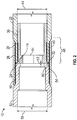
FIG. 2 depicts a magnified cross sectional view of the tubular connecting arrangement ofFIG. 1 ; -
FIG. 3 depicts a cross sectional view of an alternative embodiment of a tubular connecting arrangement disclosed herein; -
FIG. 4 depicts a cross sectional view of another alternative embodiment of a tubular connecting arrangement; and -
FIG. 5 depicts a cross sectional view another alternative embodiment of a tubular connecting arrangement. - A detailed description of one or more embodiments of the disclosed apparatus and method are presented herein by way of exemplification and not limitation with reference to the Figures.
- Referring to
Figures 1 and2 a tubular connecting arrangement disclosed herein is illustrated generally at 10. Thetubular connecting arrangement 10 includes a first tubular 12 having afirst shoulder 14 andfirst threads 16 and a second tubular 22 having asecond shoulder 24,second threads 26 andthird threads 28. Aseal 32 is sealingly engagable with both thefirst shoulder 14 and thesecond shoulder 24. And aninsert 36 is threadably engagable with thethird threads 28 and configured to provide at least radial support to the second tubular 22. Asleeve 40 is threadably engagable with both thefirst threads 16 and thesecond threads 26 in response to being rotated in a same direction relative to both the first tubular 12 and the second tubular 22. This threadable engagement causes thefirst shoulder 14 and thesecond shoulder 24 to move toward one another and compress theseal 32 therebetween without requiring the first tubular 12 to rotate relative to the second tubular 22. - The foregoing structure allows the second tubular 22 to have a minimum inner
radial dimension 44 that is larger further from anend portion 48 than nearer to theend portion 48 while still maintaining enough wall thickness of the second tubular 22 near theend portion 48. This is because theinsert 36 provides structural radial and axial support to theend portion 48 of the second tubular 22 that is needed to prevent damage to theend portion 48 that could occur due to high loads transmitted thereto from the first tubular 12 and imparted thereto from pressure surrounding the second tubular 22. (Of course an alternative approach would be to just make the wall thickness of the second tubular 22 thicker throughout its full length. Doing so however would result in any tool being installed inside the second tubular 22 having a smaller inner radial dimension than that of the second tubular 22, which is a condition the use of theinsert 36 avoids.) The loads from the first tubular 12 include axially compressive and axially tensive loads due to bending forces applied across thetubular connecting arrangement 10. These axial loads could result in leakage past theseal 32 due to changes in a gap dimension 52 (defined between the twoshoulders 14 and 24) and subsequent changes in compression of theseal 32 outside of a desired compression range. Such changes in the compressive loading of theend portion 48 of thesecond tubular 22 could occur if theinsert 36 were not present. Additionally, theinsert 36 may include athird shoulder 54 that contacts thefirst shoulder 14 thereby supporting at least some of the axial load from the first tubular 12 directly. Theinsert 36 allows the minimum innerradial dimension 44 to be as large as a minimum innerradial dimension 56 of the first tubular 12 in areas other than near where thefirst threads 16 are located. As such, tools (not shown) such as sensor probes, for example, that are generally tubular shaped can be installed into the second tubular 22 prior to engaging theinsert 36 into the second tubular 22. The tools could have an outer radial dimension that substantially matches the minimumradial dimension 44 and inner radial dimensions that match those of theinsert 36. - Although the
insert 36 is attached to the second tubular 22 in the embodiment ofFigures 1 and2 , alternate embodiments may instead attach an insert to a second tubular via welding, bonding, clamping, soldering and combinations of the foregoing. - In the embodiment of
Figures 1 and2 , theinsert 36 includes anoptional flange 60 that extends radially outwardly from the rest of theinsert 36 and abuts thesecond shoulder 24 when theinsert 36 is fully threadably engaged with the second tubular 22. Theflange 60 in this embodiment acts as a stop for the threadable engagement of theinsert 36 to the second tubular 22. Theflange 60 can also help prevent agap dimension 60 between theshoulders flange 60 theinsert 36 can be configured to bottom out with thesecond threads 26 at a location such that thethird shoulder 54 is positioned at the desired location relative to the second tubular 22. - The
insert 36 in the illustrated embodiment also includes an optional noncircularinner portion 64. Theinner portion 64 is receptive to a tool (not shown) for applying torque to theinsert 36 when threadably engaging theinsert 36 into the second tubular 22. Although theinner portion 64 of the embodiment shown is hexagonal, any noncircular shape including, a square, triangular, pentagonal, oval, star shaped, and octagonal, for example, would suffice. - Referring to
Figure 3 an alternate embodiment of a tubular connecting arrangement disclosed herein is illustrated at 110. Components in thearrangement 110 that are similar to components of thearrangement 10 are designated with the same reference characters and are not described again hereunder. Aninsert 136 of thearrangement 110 is threadably engaged withinthird threads 128 to a position deeper within a second tubular 122 than that of thearrangement 10. Athird shoulder 154 on theinsert 136 is abutted by afourth shoulder 166 of a first tubular 112 to help carry loads between the first tubular 112 and thesecond tubular 122. - An
optional key 168 positioned within arecess 170 in thesecond tubular 122 engages aslot 172 in the first tubular 112 to prevent relative rotation between thetubulars sleeve 40 is being threadably engaged with thefirst threads 16 and thesecond threads 26. Alternatively tools could be positioned externally to thetubulars sleeve 40 is being threadably engaged therewith. An optionalfifth shoulder 176 on the either or both of thefirst tubular 112 or the second tubular 122 (shown in this embodiment on only the first tubular 112) contacts ashoulder first tubular 112 or the second tubular 122 to help support axially loads between thetubulars gap dimension 52 needed for theseal 32 to maintain sealing integrity. - Referring to
Figure 4 an alternate embodiment of a tubular connecting arrangement disclosed herein is illustrated at 210. Components in thearrangement 210 that are similar to components of thearrangement 10 are designated with the same reference characters and are not described again hereunder. Acollar 237 of thearrangement 210 is threadably engaged withinfourth threads 229 in a first tubular 212. Asixth shoulder 255 on thecollar 237 abuts thethird shoulder 54 on theinsert 36 to help carry loads between thefirst tubular 212 and thesecond tubular 22. Anoptional flange 261 of thecollar 237 and theflange 60 of theinsert 36 together define and help maintain thegap dimension 52 and sealing integrity of theseal 32 to thefirst shoulder 14 and thesecond shoulder 24. The foregoing structure allows the minimumradial dimension 56 of the first tubular 212 to continue through anend portion 249 of thefirst tubular 212. This allows for tools such as sensor probes to be installed within the first tubular 212 as well as within thesecond tubular 22 without having to reduce radial dimensions thereof below those of the minimumradial dimensions - Referring to
Figure 5 an alternate embodiment of a tubular connecting arrangement disclosed herein is illustrated at 310. Thearrangement 310 is similar to thearrangement 10 with the major difference being that aninsert 336 of thearrangement 310 is threadably engaged within both thethird threads 28 of thesecond tubular 22 and thefourth threads 229 of thefirst tubular 12. Theinsert 336 includes aflange 360 that defines and helps maintain thegap dimension 52 and sealing integrity of theseal 32 to thefirst shoulder 14 and thesecond shoulder 24. - The
seal 32 is employed in the embodiments illustrated is "C" shaped and is made of metal, although other embodiment may employ seals made of polymers, elastomers and other materials. Also seals with cross sectional shapes other than "C" shaped may also be employed in embodiments. For embodiments with theseal 32 being made of metal at least one of theseal 32, thefirst shoulder 14 and the second 24 may be plated with a coating of gold, silver, copper or PTFE. Further at least one of theseal 32, thefirst shoulder 14 and the second 24 may have a surface roughness of less than about Ra 1.6. Since metals tend to have higher temperature tolerance than other materials making theseal 32 out of metal may increase temperature as well as pressures at which thearrangements seal 32. Additionally, embodiments disclosed herein prevent relative rotational motion between theseal 32 and theshoulders shoulders seal 32 and any surface coatings or treatments to surfaces of these. - While the invention has been described with reference to an exemplary embodiment or embodiments, it will be understood by those skilled in the art that various changes may be made and equivalents may be substituted for elements thereof without departing from the scope of the invention. In addition, many modifications may be made to adapt a particular situation or material to the teachings of the invention without departing from the essential scope thereof. Therefore, it is intended that the invention not be limited to the particular embodiment disclosed as the best mode contemplated for carrying out this invention, but that the invention will include all embodiments falling within the scope of the claims. Also, in the drawings and the description, there have been disclosed exemplary embodiments of the invention and, although specific terms may have been employed, they are unless otherwise stated used in a generic and descriptive sense only and not for purposes of limitation, the scope of the invention therefore not being so limited. Moreover, the use of the terms first, second, etc. do not denote any order or importance, but rather the terms first, second, etc. are used to distinguish one element from another. Furthermore, the use of the terms a, an, etc. do not denote a limitation of quantity, but rather denote the presence of at least one of the referenced item.
Claims (14)
- A tubular connecting arrangement (10, 210, 310) characterized by:a first tubular (12) having a first shoulder (14) and first threads (16);a second tubular (22) having a second shoulder (24) and second threads (26);a seal (32) designed to be sealingly engageable to both the first shoulder (14) and the second shoulder (24);an insert (36, 336) designed to be attachable to the second tubular (22), the insert (36, 336) being configured to provide radial support to the second tubular (22) and including a flange (60, 360) that is compressed between the first shoulder (14) and the second shoulder (24) when the seal (32) is sealingly engaged with the first shoulder (14) and the second shoulder (24); anda sleeve (40) designed to be threadably engageable with both the first threads (16) and the second threads (26) in response to being rotated in a same direction relative to both the first tubular (12) and the second tubular (22) such that the first shoulder (14) and the second shoulder (24) are moved toward one another to compress the seal (32) therebetween without rotational movement of the first tubular (12) relative to the second tubular (22).
- The tubular connecting arrangement (210) of claim 1 further comprising:
a collar (237) threadably engaged within fourth threads (229) in the first tubular (12,212). - The tubular connecting arrangement (210) of claim 2, wherein the collar (237) comprises a flange (261) such that the flange (261) of the collar (237) and the flange (60) of the insert (36) together define a gap dimension (52) between the first shoulder (14) and the second shoulder (24).
- The tubular connecting arrangement (10, 210, 310) of claim 1, wherein at least one of the first tubular (12, 212) and the second tubular (22) having a minimum inner radial dimension (56, 44) and configured to accept a tool having an outer radial dimension that fits within the minimum inner radial dimension (56, 44) of the at least one of the first tubular (12, 212) and the second tubular (22).
- The tubular connecting arrangement (10, 210, 310) of claim 1, wherein a minimum inner radial dimension of the second tubular (22) is greater than a minimum inner radial dimension of the insert (336).
- The tubular connecting arrangement (10, 210, 310) of claim 1, wherein the insert (36, 336) has a noncircular inner surface receptive to a tool to allow torque to be applied to the insert (36, 336) by the tool.
- The tubular connecting arrangement (10, 210, 310) of claim 1, wherein the seal (32) is made of metal.
- The tubular connecting arrangement (10, 210, 310) of claim 7, wherein the first shoulder (14) and the second shoulder (24) are plated with a coating of gold, silver, copper or PTFE.
- The tubular connecting arrangement (10, 210, 310) of claim 7, wherein the first shoulder (14) and the second shoulder (24) have a surface roughness of less than Ra 1.6.
- The tubular connecting arrangement (10, 210, 310) of claim 1, wherein the second tubular (22) has third threads (28) on an inside thereof of the second tubular (22) and the insert (36, 336) is threadably engagable with the third threads (28).
- The tubular connecting arrangement (10, 210, 310) of claim 1, wherein the insert (36, 336) is attached to the second tubular (22) via welding, bonding, clamping, soldering or combinations of the foregoing.
- A method of sealingly connecting tubulars using a tubular connecting arrangement (10, 210, 310) according to one of claims 1 to 12, the method comprising:rotating the sleeve (40) threadably engaged with both the first tubular (12) and the second tubular (22);attaching the insert (36, 336) within the second tubular (22);sealingly compressing the seal (32) between the first shoulder (14) on the first tubular (12) and the second shoulder (24) on the second tubular (22) without relative rotation between the first tubular (12) and the second tubular (22); andradially supporting the second tubular (22) with the insert (36, 336).
- The method of sealingly connecting tubulars of claim 12, wherein at least one of the first tubular (12, 212) and the second tubular (22) having a minimum inner radial dimension (56, 44) and configured to accept a tool having an outer radial dimension that fits within the minimum inner radial dimension (56, 44) of the at least one of the first tubular (12, 212) and the second tubular (22), the method further comprising:
installing the tool in at least one of the first tubular (12, 212) and the second tubular (22) prior to attaching the insert (36, 336) to the second tubular (22). - The method of sealingly connecting tubulars of claim 12, further comprising:
threadably engaging a collar (237) within fourth threads (229) in the first tubular (12, 212).
Applications Claiming Priority (3)
| Application Number | Priority Date | Filing Date | Title |
|---|---|---|---|
| US14/271,688 US10066768B2 (en) | 2014-05-07 | 2014-05-07 | Tubular connecting arrangement and method of sealingly connecting tubulars |
| EP15788968.4A EP3140579B1 (en) | 2014-05-07 | 2015-05-06 | Tubular connecting arrangement and method of sealingly connecting tubulars |
| PCT/US2015/029473 WO2015171768A1 (en) | 2014-05-07 | 2015-05-06 | Tubular connecting arrangement and method of sealingly connecting tubulars |
Related Parent Applications (2)
| Application Number | Title | Priority Date | Filing Date |
|---|---|---|---|
| EP15788968.4A Division-Into EP3140579B1 (en) | 2014-05-07 | 2015-05-06 | Tubular connecting arrangement and method of sealingly connecting tubulars |
| EP15788968.4A Division EP3140579B1 (en) | 2014-05-07 | 2015-05-06 | Tubular connecting arrangement and method of sealingly connecting tubulars |
Publications (2)
| Publication Number | Publication Date |
|---|---|
| EP3584485A1 true EP3584485A1 (en) | 2019-12-25 |
| EP3584485B1 EP3584485B1 (en) | 2021-11-10 |
Family
ID=54367477
Family Applications (2)
| Application Number | Title | Priority Date | Filing Date |
|---|---|---|---|
| EP19191155.1A Active EP3584485B1 (en) | 2014-05-07 | 2015-05-06 | Tubular connecting arrangement and method of sealingly connecting tubulars |
| EP15788968.4A Active EP3140579B1 (en) | 2014-05-07 | 2015-05-06 | Tubular connecting arrangement and method of sealingly connecting tubulars |
Family Applications After (1)
| Application Number | Title | Priority Date | Filing Date |
|---|---|---|---|
| EP15788968.4A Active EP3140579B1 (en) | 2014-05-07 | 2015-05-06 | Tubular connecting arrangement and method of sealingly connecting tubulars |
Country Status (5)
| Country | Link |
|---|---|
| US (2) | US10066768B2 (en) |
| EP (2) | EP3584485B1 (en) |
| CN (1) | CN106489047B (en) |
| BR (1) | BR112016026036B1 (en) |
| WO (1) | WO2015171768A1 (en) |
Families Citing this family (12)
| Publication number | Priority date | Publication date | Assignee | Title |
|---|---|---|---|---|
| US10066768B2 (en) | 2014-05-07 | 2018-09-04 | Baker Hughes, A Ge Company, Llc | Tubular connecting arrangement and method of sealingly connecting tubulars |
| CN105284035B (en) | 2014-05-09 | 2018-09-04 | 三菱电机株式会社 | Rotating electrical machine and component cable temperature measuring sensor installation method of rotating electrical machine |
| EP3633256B1 (en) * | 2017-05-22 | 2021-09-29 | Nippon Steel Corporation | Threaded connection for pipes or tubes and method for producing the threaded connection for pipes or tubes |
| US20200190915A1 (en) * | 2018-12-18 | 2020-06-18 | Baker Hughes, A Ge Company, Llc | Guiding sleeve for aligning downhole tubulars |
| CN110617547A (en) * | 2019-09-11 | 2019-12-27 | 山东智汇新谷科技企业孵化器有限公司 | Ground-environment greenhouse air source heat pump unit |
| CN113389926B (en) * | 2020-03-12 | 2026-01-02 | 上海盛唐阀门科技股份有限公司 | A spring-return ball valve with good sealing performance |
| NO346672B1 (en) * | 2021-02-12 | 2022-11-21 | Fladby Connector As | A pipe coupling |
| CN113700953A (en) * | 2021-09-18 | 2021-11-26 | 五行科技股份有限公司 | Pipeline connecting assembly |
| US20250164152A1 (en) * | 2022-03-15 | 2025-05-22 | Martin Hadlauer | Absorber unit, mirror unit and solar collector or solar installation |
| WO2023198403A1 (en) * | 2022-04-12 | 2023-10-19 | Asml Netherlands B.V. | High pressure coupling assembly |
| CN115854138B (en) * | 2022-12-19 | 2026-01-09 | 珠海格力智能装备有限公司 | Piping connection structure and household appliances |
| US20250067375A1 (en) * | 2023-08-21 | 2025-02-27 | Robroy Industries - Texas, LLC | Fitting Configured to Connect and Transition into a Conduit Body |
Citations (4)
| Publication number | Priority date | Publication date | Assignee | Title |
|---|---|---|---|---|
| US236957A (en) * | 1881-01-25 | Pipe-coupling | ||
| US3476409A (en) * | 1967-06-14 | 1969-11-04 | Benteler Werke Ag | Pipe union |
| US3672705A (en) * | 1970-06-19 | 1972-06-27 | Garren Corp | Pipe jack |
| US6604761B1 (en) * | 2000-01-05 | 2003-08-12 | Saint-Gobain Vetrotex France S.A. | Coupling device for two pipes made of composite material based on a thermoplastic |
Family Cites Families (40)
| Publication number | Priority date | Publication date | Assignee | Title |
|---|---|---|---|---|
| US1859311A (en) * | 1926-06-01 | 1932-05-24 | Jr Joseph H Mcevoy | Pipe joint |
| US2509363A (en) * | 1948-08-19 | 1950-05-30 | Page Oil Tools Inc | Joint for pipe sections or the like |
| US3479059A (en) * | 1968-07-19 | 1969-11-18 | William B Taylor | Lined pipe sections and joints |
| US3581834A (en) | 1969-07-17 | 1971-06-01 | Smith International | Telescopic drill string unit |
| AR206593A1 (en) | 1972-03-31 | 1976-08-06 | Kainan Steel Tube Co | STRUCTURE OF COUPLING JOINTS FOR THREADED PIPES, PARTICULARLY PIPES FOR OIL WELLS |
| US4060264A (en) * | 1976-06-16 | 1977-11-29 | I-T-E Imperial Corporation Efcor Division | Swivel conduit coupling assembly |
| US4434863A (en) | 1979-05-14 | 1984-03-06 | Smith International, Inc. | Drill string splined resilient tubular telescopic joint for balanced load drilling of deep holes |
| DE3207237C2 (en) * | 1982-02-25 | 1984-06-07 | Mannesmann AG, 4000 Düsseldorf | Threaded connection for oilfield pipes |
| US4706997A (en) | 1982-05-19 | 1987-11-17 | Carstensen Kenneth J | Coupling for tubing or casing and method of assembly |
| DE3419999C2 (en) | 1984-05-29 | 1987-02-12 | Karl 7298 Loßburg Hehl | Pipe fitting with contact seal |
| US4694859A (en) | 1985-11-25 | 1987-09-22 | National Coupling Company, Inc. | Undersea hydraulic coupling and metal seal |
| GB2222785B (en) * | 1988-09-17 | 1992-02-12 | Usui Kokusai Sangyo Kk | Multi-layered pipe coating |
| US6070912A (en) | 1989-08-01 | 2000-06-06 | Reflange, Inc. | Dual seal and connection |
| US5104151A (en) * | 1991-05-15 | 1992-04-14 | Adams Don L | Coupler apparatus for connecting a conduit to an equipment opening having damaged threads |
| US5415442A (en) | 1992-03-09 | 1995-05-16 | Marubeni Tubulars, Inc. | Stabilized center-shoulder-sealed tubular connection |
| JP3081094B2 (en) | 1993-10-15 | 2000-08-28 | トヨタ自動車株式会社 | Semiconductor laser and manufacturing method thereof |
| US6425829B1 (en) | 1994-12-06 | 2002-07-30 | Nitinol Technologies, Inc. | Threaded load transferring attachment |
| WO1996029533A1 (en) | 1995-03-23 | 1996-09-26 | Hydril Company | Threaded pipe connection |
| US6568501B2 (en) * | 1998-03-11 | 2003-05-27 | Paulsson Geophysical Services, Inc. | Receiver array using tubing conveyed packer elements |
| CN2421486Y (en) * | 2000-03-30 | 2001-02-28 | 罗众名 | Loose joint for sewer pipe |
| US6666275B2 (en) | 2001-08-02 | 2003-12-23 | Halliburton Energy Services, Inc. | Bridge plug |
| US7431351B2 (en) | 2002-04-26 | 2008-10-07 | Russell Larry R | Pressure-containing tubular connections for remote operation |
| WO2005108848A2 (en) * | 2004-04-30 | 2005-11-17 | Gb Tubulars, Inc. | Improved coupling for drilling-with-casing operations |
| EP1749165A2 (en) | 2004-05-05 | 2007-02-07 | Fred N. Huston | Threaded connection for oil field applications |
| US7438329B2 (en) | 2005-01-11 | 2008-10-21 | V&M Atlas Bradford, Lp | Methods and connections for coupled pipe |
| US20060267342A1 (en) * | 2005-05-12 | 2006-11-30 | Boyd Anthony R | Tubular connection and method |
| US7434848B2 (en) * | 2005-05-12 | 2008-10-14 | Boyd Anthony R | Threaded tubular connection having interlocking tubular end structures |
| FR2895485B1 (en) | 2005-12-23 | 2012-04-13 | Vallourec Mannesmann Oil & Gas | EXTERNAL PROTECTION OF TUBULAR THREADED JOINTS FOR EXPANDING |
| DE112008001699T5 (en) | 2007-06-26 | 2010-06-10 | Swagelok Co., Solon | Line connection with sensor function |
| US8136604B2 (en) | 2009-03-13 | 2012-03-20 | Vetco Gray Inc. | Wireline run fracture isolation sleeve and plug and method of operating same |
| EP2243920A1 (en) | 2009-04-22 | 2010-10-27 | Tenaris Connections Aktiengesellschaft | Threaded joint for tubes, pipes and the like |
| EP2354603A1 (en) * | 2010-02-09 | 2011-08-10 | Carl Freudenberg KG | Seal between a fixed machine component and a second machine component rotating around it |
| US8251139B2 (en) | 2010-02-25 | 2012-08-28 | Carstensen Kenneth J | System and method for sealing couplings in downhole tubing strings |
| US10215314B2 (en) * | 2010-08-23 | 2019-02-26 | Vallourec Oil And Gas France | Tubular threaded connection |
| JP5717807B2 (en) * | 2012-07-17 | 2015-05-13 | ダイキン工業株式会社 | Female member for fittings |
| JP5783146B2 (en) * | 2012-08-08 | 2015-09-24 | 新日鐵住金株式会社 | Threaded joints for steel pipes |
| CN203215127U (en) * | 2013-04-16 | 2013-09-25 | 天津商业大学 | Detachable seal-connecting device used between pipes made of different materials |
| CN203297790U (en) * | 2013-06-04 | 2013-11-20 | 无锡金顶石油管材配件制造有限公司 | Expansion ring type pipe end connecting piece |
| CN203348771U (en) * | 2013-07-05 | 2013-12-18 | 合肥安诺新型建材有限公司 | Connecting device for skirting radiator |
| US10066768B2 (en) | 2014-05-07 | 2018-09-04 | Baker Hughes, A Ge Company, Llc | Tubular connecting arrangement and method of sealingly connecting tubulars |
-
2014
- 2014-05-07 US US14/271,688 patent/US10066768B2/en active Active
-
2015
- 2015-05-06 CN CN201580023970.6A patent/CN106489047B/en active Active
- 2015-05-06 BR BR112016026036-8A patent/BR112016026036B1/en active IP Right Grant
- 2015-05-06 WO PCT/US2015/029473 patent/WO2015171768A1/en not_active Ceased
- 2015-05-06 EP EP19191155.1A patent/EP3584485B1/en active Active
- 2015-05-06 EP EP15788968.4A patent/EP3140579B1/en active Active
-
2018
- 2018-08-01 US US16/052,296 patent/US10753517B2/en active Active
Patent Citations (4)
| Publication number | Priority date | Publication date | Assignee | Title |
|---|---|---|---|---|
| US236957A (en) * | 1881-01-25 | Pipe-coupling | ||
| US3476409A (en) * | 1967-06-14 | 1969-11-04 | Benteler Werke Ag | Pipe union |
| US3672705A (en) * | 1970-06-19 | 1972-06-27 | Garren Corp | Pipe jack |
| US6604761B1 (en) * | 2000-01-05 | 2003-08-12 | Saint-Gobain Vetrotex France S.A. | Coupling device for two pipes made of composite material based on a thermoplastic |
Also Published As
| Publication number | Publication date |
|---|---|
| EP3140579A1 (en) | 2017-03-15 |
| US10753517B2 (en) | 2020-08-25 |
| WO2015171768A1 (en) | 2015-11-12 |
| US20150323108A1 (en) | 2015-11-12 |
| EP3140579B1 (en) | 2020-07-01 |
| US20180340636A1 (en) | 2018-11-29 |
| EP3584485B1 (en) | 2021-11-10 |
| CN106489047B (en) | 2020-02-18 |
| CN106489047A (en) | 2017-03-08 |
| EP3140579A4 (en) | 2017-12-20 |
| BR112016026036B1 (en) | 2021-07-20 |
| US10066768B2 (en) | 2018-09-04 |
Similar Documents
| Publication | Publication Date | Title |
|---|---|---|
| US10753517B2 (en) | Tubular connecting arrangement and method of sealingly connecting tubulars | |
| EP3126096B1 (en) | Interface device for tensioning a nut and a bolt assembly | |
| KR20190104641A (en) | Push to connect conduit fitting with ferrule | |
| US8727315B2 (en) | Ball valve | |
| RU2722195C2 (en) | Tubular element with screw stop | |
| WO2008100644B1 (en) | Mechanically coupled screen and method | |
| FI3015751T4 (en) | Fitting for connecting to a tubular element, tubing connection and a method for connecting a fitting to a tubular element | |
| US10190709B2 (en) | Systems and methods of coupling pipes | |
| CN104769211B (en) | Seal assembly for casing hanger | |
| JP6757718B2 (en) | Pipe connecting device | |
| CN107531274B (en) | Piston Assembly | |
| US9850732B2 (en) | Seal assembly for a downhole device | |
| EP2643598B1 (en) | Retaining ring | |
| WO2016049451A3 (en) | Internal tieback with outer diameter sealing capability | |
| US10443769B2 (en) | Pivot joint | |
| WO2008147707A4 (en) | A self energizing seal element | |
| RU99053U1 (en) | HIGH SEAL THREADED DRILL PIPE JOINT | |
| US20180313167A1 (en) | Systems And Methods For Threadably Connecting An Object With A Cylinder | |
| WO2014038954A1 (en) | Seal assembly and seal ring | |
| US7591488B2 (en) | Fitting particularly for high-pressure pipes | |
| US20120160572A1 (en) | Vibration-Resistant Seal for Downhole Tool | |
| RU2548257C1 (en) | Method of tightness keeping of thread joint of casing string |
Legal Events
| Date | Code | Title | Description |
|---|---|---|---|
| PUAI | Public reference made under article 153(3) epc to a published international application that has entered the european phase |
Free format text: ORIGINAL CODE: 0009012 |
|
| STAA | Information on the status of an ep patent application or granted ep patent |
Free format text: STATUS: THE APPLICATION HAS BEEN PUBLISHED |
|
| AC | Divisional application: reference to earlier application |
Ref document number: 3140579 Country of ref document: EP Kind code of ref document: P |
|
| AK | Designated contracting states |
Kind code of ref document: A1 Designated state(s): AL AT BE BG CH CY CZ DE DK EE ES FI FR GB GR HR HU IE IS IT LI LT LU LV MC MK MT NL NO PL PT RO RS SE SI SK SM TR |
|
| STAA | Information on the status of an ep patent application or granted ep patent |
Free format text: STATUS: REQUEST FOR EXAMINATION WAS MADE |
|
| 17P | Request for examination filed |
Effective date: 20200623 |
|
| RBV | Designated contracting states (corrected) |
Designated state(s): AL AT BE BG CH CY CZ DE DK EE ES FI FR GB GR HR HU IE IS IT LI LT LU LV MC MK MT NL NO PL PT RO RS SE SI SK SM TR |
|
| GRAP | Despatch of communication of intention to grant a patent |
Free format text: ORIGINAL CODE: EPIDOSNIGR1 |
|
| STAA | Information on the status of an ep patent application or granted ep patent |
Free format text: STATUS: GRANT OF PATENT IS INTENDED |
|
| INTG | Intention to grant announced |
Effective date: 20210624 |
|
| RAP3 | Party data changed (applicant data changed or rights of an application transferred) |
Owner name: BAKER HUGHES HOLDINGS LLC |
|
| GRAS | Grant fee paid |
Free format text: ORIGINAL CODE: EPIDOSNIGR3 |
|
| GRAA | (expected) grant |
Free format text: ORIGINAL CODE: 0009210 |
|
| STAA | Information on the status of an ep patent application or granted ep patent |
Free format text: STATUS: THE PATENT HAS BEEN GRANTED |
|
| AC | Divisional application: reference to earlier application |
Ref document number: 3140579 Country of ref document: EP Kind code of ref document: P |
|
| AK | Designated contracting states |
Kind code of ref document: B1 Designated state(s): AL AT BE BG CH CY CZ DE DK EE ES FI FR GB GR HR HU IE IS IT LI LT LU LV MC MK MT NL NO PL PT RO RS SE SI SK SM TR |
|
| REG | Reference to a national code |
Ref country code: GB Ref legal event code: FG4D |
|
| REG | Reference to a national code |
Ref country code: AT Ref legal event code: REF Ref document number: 1446391 Country of ref document: AT Kind code of ref document: T Effective date: 20211115 Ref country code: CH Ref legal event code: EP |
|
| REG | Reference to a national code |
Ref country code: DE Ref legal event code: R096 Ref document number: 602015075005 Country of ref document: DE |
|
| REG | Reference to a national code |
Ref country code: IE Ref legal event code: FG4D |
|
| REG | Reference to a national code |
Ref country code: NO Ref legal event code: T2 Effective date: 20211110 |
|
| REG | Reference to a national code |
Ref country code: LT Ref legal event code: MG9D |
|
| REG | Reference to a national code |
Ref country code: NL Ref legal event code: MP Effective date: 20211110 |
|
| REG | Reference to a national code |
Ref country code: AT Ref legal event code: MK05 Ref document number: 1446391 Country of ref document: AT Kind code of ref document: T Effective date: 20211110 |
|
| PG25 | Lapsed in a contracting state [announced via postgrant information from national office to epo] |
Ref country code: RS Free format text: LAPSE BECAUSE OF FAILURE TO SUBMIT A TRANSLATION OF THE DESCRIPTION OR TO PAY THE FEE WITHIN THE PRESCRIBED TIME-LIMIT Effective date: 20211110 Ref country code: LT Free format text: LAPSE BECAUSE OF FAILURE TO SUBMIT A TRANSLATION OF THE DESCRIPTION OR TO PAY THE FEE WITHIN THE PRESCRIBED TIME-LIMIT Effective date: 20211110 Ref country code: FI Free format text: LAPSE BECAUSE OF FAILURE TO SUBMIT A TRANSLATION OF THE DESCRIPTION OR TO PAY THE FEE WITHIN THE PRESCRIBED TIME-LIMIT Effective date: 20211110 Ref country code: BG Free format text: LAPSE BECAUSE OF FAILURE TO SUBMIT A TRANSLATION OF THE DESCRIPTION OR TO PAY THE FEE WITHIN THE PRESCRIBED TIME-LIMIT Effective date: 20220210 Ref country code: AT Free format text: LAPSE BECAUSE OF FAILURE TO SUBMIT A TRANSLATION OF THE DESCRIPTION OR TO PAY THE FEE WITHIN THE PRESCRIBED TIME-LIMIT Effective date: 20211110 |
|
| PG25 | Lapsed in a contracting state [announced via postgrant information from national office to epo] |
Ref country code: IS Free format text: LAPSE BECAUSE OF FAILURE TO SUBMIT A TRANSLATION OF THE DESCRIPTION OR TO PAY THE FEE WITHIN THE PRESCRIBED TIME-LIMIT Effective date: 20220310 Ref country code: SE Free format text: LAPSE BECAUSE OF FAILURE TO SUBMIT A TRANSLATION OF THE DESCRIPTION OR TO PAY THE FEE WITHIN THE PRESCRIBED TIME-LIMIT Effective date: 20211110 Ref country code: PT Free format text: LAPSE BECAUSE OF FAILURE TO SUBMIT A TRANSLATION OF THE DESCRIPTION OR TO PAY THE FEE WITHIN THE PRESCRIBED TIME-LIMIT Effective date: 20220310 Ref country code: PL Free format text: LAPSE BECAUSE OF FAILURE TO SUBMIT A TRANSLATION OF THE DESCRIPTION OR TO PAY THE FEE WITHIN THE PRESCRIBED TIME-LIMIT Effective date: 20211110 Ref country code: NL Free format text: LAPSE BECAUSE OF FAILURE TO SUBMIT A TRANSLATION OF THE DESCRIPTION OR TO PAY THE FEE WITHIN THE PRESCRIBED TIME-LIMIT Effective date: 20211110 Ref country code: LV Free format text: LAPSE BECAUSE OF FAILURE TO SUBMIT A TRANSLATION OF THE DESCRIPTION OR TO PAY THE FEE WITHIN THE PRESCRIBED TIME-LIMIT Effective date: 20211110 Ref country code: HR Free format text: LAPSE BECAUSE OF FAILURE TO SUBMIT A TRANSLATION OF THE DESCRIPTION OR TO PAY THE FEE WITHIN THE PRESCRIBED TIME-LIMIT Effective date: 20211110 Ref country code: GR Free format text: LAPSE BECAUSE OF FAILURE TO SUBMIT A TRANSLATION OF THE DESCRIPTION OR TO PAY THE FEE WITHIN THE PRESCRIBED TIME-LIMIT Effective date: 20220211 Ref country code: ES Free format text: LAPSE BECAUSE OF FAILURE TO SUBMIT A TRANSLATION OF THE DESCRIPTION OR TO PAY THE FEE WITHIN THE PRESCRIBED TIME-LIMIT Effective date: 20211110 |
|
| PG25 | Lapsed in a contracting state [announced via postgrant information from national office to epo] |
Ref country code: SM Free format text: LAPSE BECAUSE OF FAILURE TO SUBMIT A TRANSLATION OF THE DESCRIPTION OR TO PAY THE FEE WITHIN THE PRESCRIBED TIME-LIMIT Effective date: 20211110 Ref country code: SK Free format text: LAPSE BECAUSE OF FAILURE TO SUBMIT A TRANSLATION OF THE DESCRIPTION OR TO PAY THE FEE WITHIN THE PRESCRIBED TIME-LIMIT Effective date: 20211110 Ref country code: RO Free format text: LAPSE BECAUSE OF FAILURE TO SUBMIT A TRANSLATION OF THE DESCRIPTION OR TO PAY THE FEE WITHIN THE PRESCRIBED TIME-LIMIT Effective date: 20211110 Ref country code: EE Free format text: LAPSE BECAUSE OF FAILURE TO SUBMIT A TRANSLATION OF THE DESCRIPTION OR TO PAY THE FEE WITHIN THE PRESCRIBED TIME-LIMIT Effective date: 20211110 Ref country code: DK Free format text: LAPSE BECAUSE OF FAILURE TO SUBMIT A TRANSLATION OF THE DESCRIPTION OR TO PAY THE FEE WITHIN THE PRESCRIBED TIME-LIMIT Effective date: 20211110 Ref country code: CZ Free format text: LAPSE BECAUSE OF FAILURE TO SUBMIT A TRANSLATION OF THE DESCRIPTION OR TO PAY THE FEE WITHIN THE PRESCRIBED TIME-LIMIT Effective date: 20211110 |
|
| REG | Reference to a national code |
Ref country code: DE Ref legal event code: R097 Ref document number: 602015075005 Country of ref document: DE |
|
| PLBE | No opposition filed within time limit |
Free format text: ORIGINAL CODE: 0009261 |
|
| STAA | Information on the status of an ep patent application or granted ep patent |
Free format text: STATUS: NO OPPOSITION FILED WITHIN TIME LIMIT |
|
| 26N | No opposition filed |
Effective date: 20220811 |
|
| PG25 | Lapsed in a contracting state [announced via postgrant information from national office to epo] |
Ref country code: AL Free format text: LAPSE BECAUSE OF FAILURE TO SUBMIT A TRANSLATION OF THE DESCRIPTION OR TO PAY THE FEE WITHIN THE PRESCRIBED TIME-LIMIT Effective date: 20211110 |
|
| PG25 | Lapsed in a contracting state [announced via postgrant information from national office to epo] |
Ref country code: SI Free format text: LAPSE BECAUSE OF FAILURE TO SUBMIT A TRANSLATION OF THE DESCRIPTION OR TO PAY THE FEE WITHIN THE PRESCRIBED TIME-LIMIT Effective date: 20211110 |
|
| REG | Reference to a national code |
Ref country code: DE Ref legal event code: R119 Ref document number: 602015075005 Country of ref document: DE |
|
| REG | Reference to a national code |
Ref country code: CH Ref legal event code: PL |
|
| REG | Reference to a national code |
Ref country code: BE Ref legal event code: MM Effective date: 20220531 |
|
| PG25 | Lapsed in a contracting state [announced via postgrant information from national office to epo] |
Ref country code: MC Free format text: LAPSE BECAUSE OF FAILURE TO SUBMIT A TRANSLATION OF THE DESCRIPTION OR TO PAY THE FEE WITHIN THE PRESCRIBED TIME-LIMIT Effective date: 20211110 Ref country code: LU Free format text: LAPSE BECAUSE OF NON-PAYMENT OF DUE FEES Effective date: 20220506 Ref country code: LI Free format text: LAPSE BECAUSE OF NON-PAYMENT OF DUE FEES Effective date: 20220531 Ref country code: CH Free format text: LAPSE BECAUSE OF NON-PAYMENT OF DUE FEES Effective date: 20220531 |
|
| PG25 | Lapsed in a contracting state [announced via postgrant information from national office to epo] |
Ref country code: IE Free format text: LAPSE BECAUSE OF NON-PAYMENT OF DUE FEES Effective date: 20220506 Ref country code: FR Free format text: LAPSE BECAUSE OF NON-PAYMENT OF DUE FEES Effective date: 20220531 |
|
| PG25 | Lapsed in a contracting state [announced via postgrant information from national office to epo] |
Ref country code: IT Free format text: LAPSE BECAUSE OF FAILURE TO SUBMIT A TRANSLATION OF THE DESCRIPTION OR TO PAY THE FEE WITHIN THE PRESCRIBED TIME-LIMIT Effective date: 20211110 Ref country code: DE Free format text: LAPSE BECAUSE OF NON-PAYMENT OF DUE FEES Effective date: 20221201 Ref country code: BE Free format text: LAPSE BECAUSE OF NON-PAYMENT OF DUE FEES Effective date: 20220531 |
|
| P01 | Opt-out of the competence of the unified patent court (upc) registered |
Effective date: 20230526 |
|
| PG25 | Lapsed in a contracting state [announced via postgrant information from national office to epo] |
Ref country code: MK Free format text: LAPSE BECAUSE OF FAILURE TO SUBMIT A TRANSLATION OF THE DESCRIPTION OR TO PAY THE FEE WITHIN THE PRESCRIBED TIME-LIMIT Effective date: 20211110 Ref country code: CY Free format text: LAPSE BECAUSE OF FAILURE TO SUBMIT A TRANSLATION OF THE DESCRIPTION OR TO PAY THE FEE WITHIN THE PRESCRIBED TIME-LIMIT Effective date: 20211110 |
|
| PG25 | Lapsed in a contracting state [announced via postgrant information from national office to epo] |
Ref country code: HU Free format text: LAPSE BECAUSE OF FAILURE TO SUBMIT A TRANSLATION OF THE DESCRIPTION OR TO PAY THE FEE WITHIN THE PRESCRIBED TIME-LIMIT; INVALID AB INITIO Effective date: 20150506 |
|
| PG25 | Lapsed in a contracting state [announced via postgrant information from national office to epo] |
Ref country code: TR Free format text: LAPSE BECAUSE OF FAILURE TO SUBMIT A TRANSLATION OF THE DESCRIPTION OR TO PAY THE FEE WITHIN THE PRESCRIBED TIME-LIMIT Effective date: 20211110 |
|
| PG25 | Lapsed in a contracting state [announced via postgrant information from national office to epo] |
Ref country code: MT Free format text: LAPSE BECAUSE OF FAILURE TO SUBMIT A TRANSLATION OF THE DESCRIPTION OR TO PAY THE FEE WITHIN THE PRESCRIBED TIME-LIMIT Effective date: 20211110 |
|
| PGFP | Annual fee paid to national office [announced via postgrant information from national office to epo] |
Ref country code: GB Payment date: 20250423 Year of fee payment: 11 |
|
| PGFP | Annual fee paid to national office [announced via postgrant information from national office to epo] |
Ref country code: NO Payment date: 20250424 Year of fee payment: 11 |