EP3584428A1 - Control system for a gas turbine engine - Google Patents
Control system for a gas turbine engine Download PDFInfo
- Publication number
- EP3584428A1 EP3584428A1 EP19179303.3A EP19179303A EP3584428A1 EP 3584428 A1 EP3584428 A1 EP 3584428A1 EP 19179303 A EP19179303 A EP 19179303A EP 3584428 A1 EP3584428 A1 EP 3584428A1
- Authority
- EP
- European Patent Office
- Prior art keywords
- control parameter
- primary control
- bypass duct
- aircraft
- instruments
- Prior art date
- Legal status (The legal status is an assumption and is not a legal conclusion. Google has not performed a legal analysis and makes no representation as to the accuracy of the status listed.)
- Granted
Links
Images

Classifications
-
- F—MECHANICAL ENGINEERING; LIGHTING; HEATING; WEAPONS; BLASTING
- F02—COMBUSTION ENGINES; HOT-GAS OR COMBUSTION-PRODUCT ENGINE PLANTS
- F02K—JET-PROPULSION PLANTS
- F02K3/00—Plants including a gas turbine driving a compressor or a ducted fan
- F02K3/02—Plants including a gas turbine driving a compressor or a ducted fan in which part of the working fluid by-passes the turbine and combustion chamber
- F02K3/04—Plants including a gas turbine driving a compressor or a ducted fan in which part of the working fluid by-passes the turbine and combustion chamber the plant including ducted fans, i.e. fans with high volume, low pressure outputs, for augmenting the jet thrust, e.g. of double-flow type
- F02K3/06—Plants including a gas turbine driving a compressor or a ducted fan in which part of the working fluid by-passes the turbine and combustion chamber the plant including ducted fans, i.e. fans with high volume, low pressure outputs, for augmenting the jet thrust, e.g. of double-flow type with front fan
-
- B—PERFORMING OPERATIONS; TRANSPORTING
- B64—AIRCRAFT; AVIATION; COSMONAUTICS
- B64C—AEROPLANES; HELICOPTERS
- B64C19/00—Aircraft control not otherwise provided for
- B64C19/02—Conjoint controls
-
- B—PERFORMING OPERATIONS; TRANSPORTING
- B64—AIRCRAFT; AVIATION; COSMONAUTICS
- B64C—AEROPLANES; HELICOPTERS
- B64C21/00—Influencing air flow over aircraft surfaces by affecting boundary layer flow
- B64C21/02—Influencing air flow over aircraft surfaces by affecting boundary layer flow by use of slot, ducts, porous areas or the like
-
- B—PERFORMING OPERATIONS; TRANSPORTING
- B64—AIRCRAFT; AVIATION; COSMONAUTICS
- B64D—EQUIPMENT FOR FITTING IN OR TO AIRCRAFT; FLIGHT SUITS; PARACHUTES; ARRANGEMENT OR MOUNTING OF POWER PLANTS OR PROPULSION TRANSMISSIONS IN AIRCRAFT
- B64D31/00—Power plant control systems; Arrangement of power plant control systems in aircraft
- B64D31/02—Initiating means
- B64D31/06—Initiating means actuated automatically
-
- B—PERFORMING OPERATIONS; TRANSPORTING
- B64—AIRCRAFT; AVIATION; COSMONAUTICS
- B64D—EQUIPMENT FOR FITTING IN OR TO AIRCRAFT; FLIGHT SUITS; PARACHUTES; ARRANGEMENT OR MOUNTING OF POWER PLANTS OR PROPULSION TRANSMISSIONS IN AIRCRAFT
- B64D31/00—Power plant control systems; Arrangement of power plant control systems in aircraft
- B64D31/14—Transmitting means between initiating means and power plants
-
- B—PERFORMING OPERATIONS; TRANSPORTING
- B64—AIRCRAFT; AVIATION; COSMONAUTICS
- B64F—GROUND OR AIRCRAFT-CARRIER-DECK INSTALLATIONS SPECIALLY ADAPTED FOR USE IN CONNECTION WITH AIRCRAFT; DESIGNING, MANUFACTURING, ASSEMBLING, CLEANING, MAINTAINING OR REPAIRING AIRCRAFT, NOT OTHERWISE PROVIDED FOR; HANDLING, TRANSPORTING, TESTING OR INSPECTING AIRCRAFT COMPONENTS, NOT OTHERWISE PROVIDED FOR
- B64F5/00—Designing, manufacturing, assembling, cleaning, maintaining or repairing aircraft, not otherwise provided for; Handling, transporting, testing or inspecting aircraft components, not otherwise provided for
- B64F5/60—Testing or inspecting aircraft components or systems
-
- F—MECHANICAL ENGINEERING; LIGHTING; HEATING; WEAPONS; BLASTING
- F01—MACHINES OR ENGINES IN GENERAL; ENGINE PLANTS IN GENERAL; STEAM ENGINES
- F01D—NON-POSITIVE DISPLACEMENT MACHINES OR ENGINES, e.g. STEAM TURBINES
- F01D17/00—Regulating or controlling by varying flow
- F01D17/02—Arrangement of sensing elements
- F01D17/08—Arrangement of sensing elements responsive to condition of working-fluid, e.g. pressure
-
- F—MECHANICAL ENGINEERING; LIGHTING; HEATING; WEAPONS; BLASTING
- F02—COMBUSTION ENGINES; HOT-GAS OR COMBUSTION-PRODUCT ENGINE PLANTS
- F02C—GAS-TURBINE PLANTS; AIR INTAKES FOR JET-PROPULSION PLANTS; CONTROLLING FUEL SUPPLY IN AIR-BREATHING JET-PROPULSION PLANTS
- F02C9/00—Controlling gas-turbine plants; Controlling fuel supply in air- breathing jet-propulsion plants
- F02C9/26—Control of fuel supply
- F02C9/28—Regulating systems responsive to plant or ambient parameters, e.g. temperature, pressure, rotor speed
-
- G—PHYSICS
- G01—MEASURING; TESTING
- G01D—MEASURING NOT SPECIALLY ADAPTED FOR A SPECIFIC VARIABLE; ARRANGEMENTS FOR MEASURING TWO OR MORE VARIABLES NOT COVERED IN A SINGLE OTHER SUBCLASS; TARIFF METERING APPARATUS; MEASURING OR TESTING NOT OTHERWISE PROVIDED FOR
- G01D21/00—Measuring or testing not otherwise provided for
- G01D21/02—Measuring two or more variables by means not covered by a single other subclass
-
- G—PHYSICS
- G01—MEASURING; TESTING
- G01L—MEASURING FORCE, STRESS, TORQUE, WORK, MECHANICAL POWER, MECHANICAL EFFICIENCY, OR FLUID PRESSURE
- G01L15/00—Devices or apparatus for measuring two or more fluid pressure values simultaneously
-
- G—PHYSICS
- G01—MEASURING; TESTING
- G01M—TESTING STATIC OR DYNAMIC BALANCE OF MACHINES OR STRUCTURES; TESTING OF STRUCTURES OR APPARATUS, NOT OTHERWISE PROVIDED FOR
- G01M15/00—Testing of engines
- G01M15/14—Testing gas-turbine engines or jet-propulsion engines
-
- B—PERFORMING OPERATIONS; TRANSPORTING
- B64—AIRCRAFT; AVIATION; COSMONAUTICS
- B64C—AEROPLANES; HELICOPTERS
- B64C2230/00—Boundary layer controls
- B64C2230/06—Boundary layer controls by explicitly adjusting fluid flow, e.g. by using valves, variable aperture or slot areas, variable pump action or variable fluid pressure
-
- F—MECHANICAL ENGINEERING; LIGHTING; HEATING; WEAPONS; BLASTING
- F02—COMBUSTION ENGINES; HOT-GAS OR COMBUSTION-PRODUCT ENGINE PLANTS
- F02K—JET-PROPULSION PLANTS
- F02K1/00—Plants characterised by the form or arrangement of the jet pipe or nozzle; Jet pipes or nozzles peculiar thereto
- F02K1/06—Varying effective area of jet pipe or nozzle
- F02K1/15—Control or regulation
- F02K1/16—Control or regulation conjointly with another control
- F02K1/17—Control or regulation conjointly with another control with control of fuel supply
-
- F—MECHANICAL ENGINEERING; LIGHTING; HEATING; WEAPONS; BLASTING
- F02—COMBUSTION ENGINES; HOT-GAS OR COMBUSTION-PRODUCT ENGINE PLANTS
- F02K—JET-PROPULSION PLANTS
- F02K1/00—Plants characterised by the form or arrangement of the jet pipe or nozzle; Jet pipes or nozzles peculiar thereto
- F02K1/28—Plants characterised by the form or arrangement of the jet pipe or nozzle; Jet pipes or nozzles peculiar thereto using fluid jets to influence the jet flow
- F02K1/30—Plants characterised by the form or arrangement of the jet pipe or nozzle; Jet pipes or nozzles peculiar thereto using fluid jets to influence the jet flow for varying effective area of jet pipe or nozzle
-
- F—MECHANICAL ENGINEERING; LIGHTING; HEATING; WEAPONS; BLASTING
- F05—INDEXING SCHEMES RELATING TO ENGINES OR PUMPS IN VARIOUS SUBCLASSES OF CLASSES F01-F04
- F05D—INDEXING SCHEME FOR ASPECTS RELATING TO NON-POSITIVE-DISPLACEMENT MACHINES OR ENGINES, GAS-TURBINES OR JET-PROPULSION PLANTS
- F05D2260/00—Function
- F05D2260/80—Diagnostics
-
- F—MECHANICAL ENGINEERING; LIGHTING; HEATING; WEAPONS; BLASTING
- F05—INDEXING SCHEMES RELATING TO ENGINES OR PUMPS IN VARIOUS SUBCLASSES OF CLASSES F01-F04
- F05D—INDEXING SCHEME FOR ASPECTS RELATING TO NON-POSITIVE-DISPLACEMENT MACHINES OR ENGINES, GAS-TURBINES OR JET-PROPULSION PLANTS
- F05D2270/00—Control
- F05D2270/30—Control parameters, e.g. input parameters
- F05D2270/309—Rate of change of parameters
-
- G—PHYSICS
- G01—MEASURING; TESTING
- G01P—MEASURING LINEAR OR ANGULAR SPEED, ACCELERATION, DECELERATION, OR SHOCK; INDICATING PRESENCE, ABSENCE, OR DIRECTION, OF MOVEMENT
- G01P5/00—Measuring speed of fluids, e.g. of air stream; Measuring speed of bodies relative to fluids, e.g. of ship, of aircraft
- G01P5/14—Measuring speed of fluids, e.g. of air stream; Measuring speed of bodies relative to fluids, e.g. of ship, of aircraft by measuring differences of pressure in the fluid
- G01P5/16—Measuring speed of fluids, e.g. of air stream; Measuring speed of bodies relative to fluids, e.g. of ship, of aircraft by measuring differences of pressure in the fluid using Pitot tubes, e.g. Machmeter
Definitions
- the present disclosure concerns a control system for an aircraft, use of such a control system to control operation of an aircraft and a method of operating an aircraft.
- a first aspect provides a control system operable to provide a modified primary control parameter for an aircraft, the control system comprising:
- an aircraft signal say from an aircraft sensor monitoring operation of the aircraft, may cause a pilot or autopilot to implement a thrust demand for the aircraft's engine(s) to deliver increased or decreased thrust.
- the thrust demand may generate the demand in the primary control parameter.
- Deriving, and hence detecting any change in absolute levels and/or spatial distributions of swirl angle and/or fan pressure may comprise tracking or detecting a change or changes in absolute levels and/or spatial distributions, e.g. radial and/or circumferential distribution, of measured values of one or more properties of a fluid flowing in a bypass duct of the aircraft's engine(s).
- Deriving, and hence detecting any change in absolute levels and/or spatial distributions of swirl angle and/or fan pressure may comprise tracking or detecting a change or changes in absolute levels and/or spatial distributions, e.g. radial and/or circumferential distribution, of derived values of a parameter of a fluid flowing in a bypass duct of the aircraft's engine(s).
- Deriving, and hence detecting any change in absolute levels and/or spatial distributions of swirl angle and/or fan pressure may include making use of an estimate of a parameter of a fluid flowing in a bypass duct of the aircraft's engine(s).
- the aircraft's engine(s) may comprise one or more gas turbine engines.
- the aircraft's engine(s) may comprise one or more electrically driven fans.
- a method of estimating a parameter of a fluid flowing in the bypass duct may comprise:
- the fluid may comprise air.
- the common measurement plane may be at an angle to a longitudinal axis of the bypass duct.
- the common measurement plane may be at an angle of up to or at least 20°, up to or at least 30°, up to or at least 45°, up to or at least 60°, up to or at least 75° and/or up to 90° to the longitudinal axis of the bypass duct.
- the common measurement plane may be perpendicular to the longitudinal axis of the bypass duct.
- the plurality of instruments may be located within the bypass duct downstream of a propulsive fan.
- the plurality of instruments may be located within the bypass duct upstream of a cold nozzle.
- the plurality of instruments may be located in the region of one or more outlet guide vanes within the bypass duct.
- Each outlet guide vane may comprise a leading edge and a trailing edge.
- the plurality of instruments may be disposed in the vicinity of, or upstream of, the leading edge of at least one outlet guide vane.
- the plurality of instruments may be disposed in the vicinity of, or downstream of, the trailing edge of at least one outlet guide vane.
- the plurality of instruments may be disposed between the leading edge(s) and the trailing edge(s) of the outlet guide vane(s).
- the common measurement plane may be located within the bypass duct downstream of a propulsive fan.
- the common measurement plane may be located within the bypass duct upstream of a cold nozzle.
- the common measurement plane may be located in the region of one or more outlet guide vanes within the bypass duct.
- Each outlet guide vane may comprise a leading edge and a trailing edge.
- the common measurement plane may be disposed in the vicinity of, or upstream of, the leading edge of at least one outlet guide vane.
- the common measurement plane may be disposed in the vicinity of, or downstream of, the trailing edge of at least one outlet guide vane.
- the common measurement plane may be disposed between the leading edge(s) and the trailing edge(s) of the outlet guide vane(s).
- the plurality of instruments may be arranged within the common measurement plane in a regular or an irregular pattern.
- the regular pattern may comprise one or more lines of symmetry.
- the regular pattern may have two-or-higher-fold rotational symmetry.
- the regular pattern may have twofold, three-fold, four-fold, five-fold, six-fold, seven-fold, eight-fold, nine-fold, 10-fold, 11-fold or 12-fold rotational symmetry.
- the plurality of instruments may be arranged in one or more rings, each ring comprising a plurality of spaced-apart, e.g. regularly or irregularly spaced-apart, instruments.
- the plurality of instruments may be arranged in a plurality of rings.
- the plurality of rings may be concentric. In each of the rings, e.g. concentric rings, the circumferential spacing between the instruments may be the same or may vary.
- the plurality of instruments may be spaced at intervals, e.g. regularly or irregularly spaced, in a circumferential direction and/or in a radial direction.
- the property of the fluid measured by the plurality of instruments may include one or more of: pressure, e.g. static pressure or total pressure, temperature, fluid flow velocity, fluid flow speed and/or fluid flow direction, e.g. yaw angle of flow.
- Each instrument may comprise a pressure sensor.
- Each instrument may include a sensor operable to measure or derive fluid flow velocity such as a Pitot tube, or a yaw probe.
- Each instrument may comprise a sensor operable to measure or derive the direction of airflow, in addition to total and static pressure.
- Each instrument may comprise a yaw probe.
- Summing the derived values across all of the stream tubes may include integrating the derived values across all of the stream tubes.
- the derived value for each stream tube may comprise a derived fluid (mass or volume) flow value.
- the derived value for each stream tube may comprise a derived thrust value.
- the derived value for each stream tube may comprise a derived enthalpy value.
- the derived value for each stream tube may constitute an estimate.
- the parameter of the fluid flowing in the bypass duct may comprise fluid (mass or volume) flow.
- the parameter of the fluid flowing in the bypass duct may comprise thrust, e.g. gross thrust or ideal gross thrust.
- the parameter of the fluid flowing in the bypass duct may comprise enthalpy.
- the stream tubes may all have the same shape or may have one or more different shapes in cross-section within the common measurement plane.
- Each stream tube may have an annular sector shape in cross-section within the common measurement plane.
- Estimating a parameter of a fluid flowing in the bypass duct may comprise using an apparatus comprising: a plurality of instruments operable to measure a property of the fluid flowing in the bypass duct, the plurality of instruments being disposed in the bypass duct and arranged within a common measurement plane.
- the common measurement plane may be at an angle to a longitudinal axis of the bypass duct.
- the common measurement plane may be at an angle of up to or at least 20°, up to or at least 30°, up to or at least 45°, up to or at least 60°, up to or at least 75° and/or up to 90° to the longitudinal axis of the bypass duct.
- the common measurement plane may be perpendicular to the longitudinal axis of the bypass duct.
- the plurality of instruments may be located within the bypass duct downstream of a propulsive fan.
- the plurality of instruments may be located within the bypass duct upstream of a cold nozzle.
- the plurality of instruments may be located in the region of one or more outlet guide vanes within the bypass duct.
- Each outlet guide vane may comprise a leading edge and a trailing edge.
- the plurality of instruments may be disposed in the vicinity of, or upstream of, the leading edge of at least one outlet guide vane.
- the plurality of instruments may be disposed in the vicinity of, or downstream of, the trailing edge of at least one outlet guide vane.
- the plurality of instruments may be disposed between the leading edge(s) and the trailing edge(s) of the outlet guide vane(s).
- the common measurement plane may be located within the bypass duct downstream of a propulsive fan.
- the common measurement plane may be located within the bypass duct upstream of a cold nozzle.
- the common measurement plane may be located in the region of one or more outlet guide vanes within the bypass duct.
- Each outlet guide vane may comprise a leading edge and a trailing edge.
- the common measurement plane may be disposed in the vicinity of, or upstream of, the leading edge of at least one outlet guide vane.
- the common measurement plane may be disposed in the vicinity of, or downstream of, the trailing edge of at least one outlet guide vane.
- the common measurement plane may be disposed between the leading edge(s) and the trailing edge(s) of the outlet guide vane(s).
- the plurality of instruments may be arranged within the common measurement plane in a regular or an irregular pattern.
- the regular pattern may comprise one or more lines of symmetry.
- the regular pattern may have two-or-higher-fold rotational symmetry.
- the regular pattern may have twofold, three-fold, four-fold, five-fold, six-fold, seven-fold, eight-fold, nine-fold, 10-fold, 11-fold or 12-fold rotational symmetry.
- the plurality of instruments may be arranged in one or more rings, each ring comprising a plurality of spaced-apart, e.g. regularly or irregularly spaced-apart, instruments.
- the plurality of instruments may be arranged in a plurality of rings.
- the plurality of rings may be concentric. In each of the rings, e.g. concentric rings, the circumferential spacing between the instruments may be the same.
- the plurality of instruments may be spaced at intervals, e.g. regularly or irregularly spaced, in a circumferential direction and/or in a radial direction.
- the property of the fluid measured by the plurality of instruments may include one or more of: pressure, e.g. static pressure or total pressure, temperature, fluid flow velocity, fluid flow speed and/or fluid flow direction, e.g. yaw angle of flow.
- Each instrument may comprise a pressure sensor.
- Each instrument may include a sensor operable to measure or derive fluid flow velocity such as a Pitot tube, or a yaw probe.
- Each instrument may comprise a sensor operable to measure or derive the direction of airflow, in addition to total and static pressure.
- Each instrument may comprise a yaw probe.
- the apparatus may comprise one or more data storage devices, e.g. a data logger, adapted to store the measured values measured by the instruments and/or the derived values calculated using the measured values.
- the data storage device(s) may be adapted to store the measured values and/or the derived values permanently or temporarily.
- the plurality of instruments or the one or more data storage devices may be coupled to a data transmission device for transmitting the measured values to a computer or other data processing device.
- Estimating a parameter of a fluid flowing in the bypass duct may comprise using a system comprising:
- Measured values measured by the plurality of instruments may be communicated to the computer in real-time or near-real-time.
- the computer may be located remotely from the plurality of instruments.
- the measured values may be communicated continuously, intermittently or periodically, e.g. at regular intervals.
- the computer may be further adapted to generate an estimate of the parameter of the fluid flowing in the bypass duct.
- the derived value for each stream tube may comprise a derived fluid (mass or volume) flow value.
- the derived value for each stream tube may comprise a derived thrust value.
- the derived value for each stream tube may comprise a derived enthalpy value.
- the derived value for each stream tube may constitute an estimate.
- the parameter of the fluid flowing in the bypass duct may comprise fluid (mass or volume) flow.
- the parameter of the fluid flowing in the bypass duct may comprise thrust, e.g. gross thrust or ideal gross thrust.
- the parameter of the fluid flowing in the bypass duct may comprise enthalpy.
- the computer may be adapted to provide an estimate of in-flight thrust.
- a second aspect provides a gas turbine engine or an aircraft comprising a control system according to the first aspect.
- a third aspect provides a method of operating an aircraft comprising:
- An aircraft signal may cause a pilot or autopilot to implement a thrust demand for the aircraft's engine(s) to deliver increased or decreased thrust.
- the thrust demand may generate the demand in the primary control parameter.
- Deriving, and hence detecting any change in absolute levels and/or spatial distributions of swirl angle and/or fan pressure may comprise tracking or detecting a change or changes in absolute levels and/or spatial distributions, e.g. radial and/or circumferential distribution, of measured values of one or more properties of a fluid flowing in a bypass duct of the aircraft's engine(s).
- Deriving, and hence detecting any change in absolute levels and/or spatial distributions of swirl angle and/or fan pressure may comprise tracking or detecting a change or changes in absolute levels or spatial distributions, e.g. radial and/or circumferential distribution, of derived values of a parameter of a fluid flowing in the bypass duct of the aircraft's engine(s).
- Deriving, and hence detecting any change in absolute levels and/or spatial distributions of swirl angle and/or fan pressure may include making use of an estimate of a parameter of a fluid flowing in the bypass duct of the aircraft's engine(s).
- the aircraft's engine(s) may comprise one or more gas turbine engines.
- Estimating the parameter of the fluid, e.g. air, flowing in the bypass duct may be done using a method, apparatus or system disclosed herein.
- the method may be performed using a system according to the first aspect.
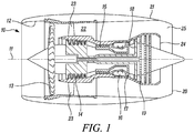
- a gas turbine engine is generally indicated at 10, having a principal and rotational axis 11.
- the engine 10 comprises, in axial flow series, an air intake 12, a propulsive fan 13, an intermediate pressure compressor 14, a high-pressure compressor 15, combustion equipment 16, a high-pressure turbine 17, an intermediate pressure turbine 18, a low-pressure turbine 19 and an exhaust nozzle 20.
- a nacelle 21 generally surrounds the engine 10 and defines both the intake 12 and the exhaust nozzle 20.
- the gas turbine engine 10 works in the conventional manner so that air entering the intake 12 is accelerated by the fan 13 to produce two air flows: a first air flow into the intermediate pressure compressor 14 and a second air flow which passes through a bypass duct 22 to provide propulsive thrust.
- the intermediate pressure compressor 14 compresses the air flow directed into it before delivering that air to the high pressure compressor 15 where further compression takes place.
- the compressed air exhausted from the high-pressure compressor 15 is directed into the combustion equipment 16 where it is mixed with fuel and the mixture combusted.
- the resultant hot combustion products then expand through, and thereby drive, the high, intermediate and low-pressure turbines 17, 18, 19 before being exhausted through the nozzle 20 to provide additional propulsive thrust.
- the high 17, intermediate 18 and low 19 pressure turbines drive respectively the high pressure compressor 15, intermediate pressure compressor 14 and fan 13, each by a suitable interconnecting shaft.
- bypass duct 22 downstream of the fan 13, there is a plurality of outlet guide vanes 23.
- the outlet guide vanes 23 are spaced at intervals circumferentially.
- the bypass duct 22 terminates at its downstream end at a cold nozzle 25.
- the cold nozzle 25 forms an annulus around a hot nozzle 24. Hot combustion products pass through the hot nozzle 24 after having driven the low pressure turbine 19.
- the cold nozzle 25 and the hot nozzle 24 communicate with the exhaust nozzle 20.
- gas turbine engines to which the present disclosure may be applied may have alternative configurations.
- such engines may have an alternative number of interconnecting shafts (e.g. two) and/or an alternative number of compressors and/or turbines.
- the engine may comprise a gearbox provided in the drive train from a turbine to a compressor and/or fan.
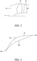
- Figure 2 shows schematically a front portion of the gas turbine engine 10, magnified relative to Figure 1 . Only one side of the principal axis 11 is shown for clarity, although it will be understood that the other side of the principal axis 11 may be generally the same as the side shown.
- the air intake 12 is upstream of the propulsive fan 13.
- FIG 3 shows one of the outlet guide vanes 23 in schematic cross-section.
- the outlet guide vane 23 has an aerofoil shape.
- the outlet guide vane 23 has two axial sides 231, 232 extending between a leading edge 233 and a trailing edge 234.
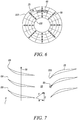
- FIG. 5 shows the bypass duct 22 in lateral cross-section at a position in the vicinity of the leading edges of the outlet guide vanes 23.
- the bypass duct 22 has the form of an annulus and is defined by an inner wall 221 and an outer wall 222. At a regular circumferential spacing, a plurality of outlet guide vanes 23 each extend radially from the inner wall 221 to the outer wall 222.
- outlet guide vanes 23 which are regularly spaced circumferentially around the bypass duct 22.
- the plurality of outlet guide vanes may comprise a different number of outlet guide vanes.
- the circumferential spacing between the outlet guide vanes may not be regular.
- An apparatus for estimating a parameter, e.g. (mass or volume) flow, of a fluid flowing in a passage is disposed in the bypass duct 22.
- the apparatus comprises a plurality of sensors 50.
- Four sensors 50 are disposed at the leading edge of every second outlet guide vane 23.
- the sensors 50 are spaced at intervals, which may be regular or irregular intervals, along the leading edge of every second outlet guide vane 23.
- four sensors 50 are disposed on eight of the 16 outlet guide vanes 23. Consequently, there is a regular pattern of 32 sensors 50 in a common measurement plane in the vicinity of the leading edges of the outlet guide vanes 23.
- the common measurement plane may coincide with the leading edges of the outlet guide vanes 23.
- the number and arrangement of the sensors 50 may vary. For instance, there may be more than or fewer than four sensors 50 disposed at the leading edge of every second outlet guide vane 23.
- the sensors 50 may be disposed at the leading edges of more than or less than half of the total number of outlet guide vanes
- the common measurement plane may be at any axial location within the bypass duct 22.
- Each sensor 50 is operable to measure or derive the direction of airflow.
- Each sensor 50 may comprise a yaw probe.
- FIG. 6 shows the same cross-section of the bypass duct 22 as in Figure 5 .
- Like features are labelled with like reference numerals. For clarity, only the outlet guide vanes 23 with sensors 50 disposed at their leading edges are shown.
- the common measurement plane is divided into 32 stream tubes 60, as indicated by the dashed lines. Each stream tube 60 represents a region of space in the common measurement plane. Each stream tube 60 has the shape of an annular sector. Each stream tube 60 includes one sensor 50 at a central location therein. The number, arrangement and shape of stream tubes 60 may vary depending on the number and arrangement of sensors in the common measurement plane.
- Figure 7 is a schematic longitudinal cross-sectional view of a portion of the bypass duct 22, including the apparatus shown in Figures 5 and 6 .
- the principal axis 11 of the gas turbine engine is indicated by a dashed line.
- the propulsive fan 13 comprises a plurality of fan rotor blades 131. Three of the fan rotor blades 131 are shown in Figure 6 .
- the fan rotor blades 131 rotate in the direction indicated by arrow 70.
- Three of the outlet guide vanes 23 are shown in Figure 7 .
- a sensor 50 which may comprise a yaw probe, is disposed at the leading edge 233 of one of the outlet guide vanes 23.
- a first vector u represents the circumferential velocity due to rotation of the propulsive fan 13.
- a second vector w represents the relative velocity of the air flow observed by the rotating fan blade.
- a third vector v represents the actual velocity vector observed by the fan outlet guide vanes 23.
- Measurements from the yaw tubes disposed at the leading edges of (at least some of) the fan outlet guide vanes may be used to derive values of total pressure, static pressure and swirl angle for each stream tube. Deriving a value for the swirl angle for each stream tube may provide information on the angle of incidence of the fluid flow with the outlet guide vanes and hence pressure loss.
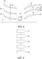
- Figure 8 is a schematic longitudinal cross-sectional view of a portion of the bypass duct 22, including another embodiment of an apparatus for estimating a parameter, e.g. (mass or volume) flow, of a fluid flowing in a passage.
- a parameter e.g. (mass or volume) flow
- the propulsive fan 13 comprises a plurality of fan rotor blades 131. Three of the fan rotor blades 131 are shown in Figure 8 . The fan rotor blades 131 rotate in the direction indicated by arrow 70. Three of the outlet guide vanes 23 are shown in Figure 8 .
- a plurality of sensors 80 are arranged in a common measurement plane a short distance downstream of the trailing edges 234 of the outlet guide vanes 23. Two of the sensors 80 are shown in Figure 8 .
- the sensors 80 are disposed such that they are each aligned longitudinally with a central part of a gap between a pair of adjacent outlet guide vanes 23.
- the plurality of sensors 80 may be arranged in a regular or irregular pattern within the common measurement plane.
- Each sensor 80 may comprise a pressure measurement instrument operable to measure fluid flow velocity such as a Pitot tube.
- Each sensor 80 may comprise a yaw tube.
- a stream tube may be associated with each sensor 80.
- a first vector u represents the circumferential velocity due to rotation of the propulsive fan 13.
- a second vector w represents the relative velocity of the air flow observed by the fan rotor blade.
- a third vector v represents the actual velocity vector observed by the fan outlet guide vanes 23.
- the sensors 80 may be located downstream of the outlet guide vanes 23 at positions where fluid flow may be or may not be disturbed by wakes from the outlet guide vanes 23.
- the sensors 80 may comprise Pitot tubes or yaw probes, which may be operable to measure total and static pressure.
- the swirl angle may be assumed to be close to the outlet guide vane outlet angle.
- the apparatuses for estimating a parameter of a fluid flowing in a passage may comprise sensors operable to measure more than one property of the fluid flowing in the passage.
- Fluid properties that may be measured may include: pressure, e.g. total pressure or static pressure, temperature, fluid flow velocity, fluid flow speed and/or fluid flow direction, e.g. yaw angle of flow.
- Measured values for each stream tube measured by the sensors 50, 80 may be stored locally, e.g. in memory in a data logger, for later analysis. The measured values may be stored temporarily or permanently. Alternatively, measured values measured by the sensors 50, 80 may be communicated to a processor or computer for processing in real-time or near-real-time. The processor or computer may be located remotely from the sensors. The measured values may be communicated continuously, intermittently or periodically, e.g. at regular intervals.
- the processor or computer is configured to use the measured value(s) for each stream tube to calculate a derived value for each stream tube.
- the processor is configured to sum the derived values across all of the stream tubes.
- the computer is configured to generate an estimate of the parameter of the fluid flowing in the passage based on the sum of the derived values across all of the stream tubes
- the parameter may be fluid (mass or volume) flow.
- the estimate of fluid flow through the passage e.g. bypass duct, may be used to provide an estimate of in-flight thrust.
- the present disclosure may reduce uncertainty of in-flight derived thrust during flight testing.
- the plurality of instruments in the common measurement plane may provide simultaneous multiple readings of one or more properties of the fluid flowing in the passage.
- the one or more properties e.g. pressure, are measured at specific radial and circumferential positions within the common measurement plane.
- a more accurate estimate of fluid (mass or volume) flow may be derivable.
- the derived estimate of fluid (mass or volume) flow may be more accurate than can be obtained using known methods such as: (i) a derived fluid (mass) flow estimate based on intake pressure measurements, as this may be inaccurate due to uncertainty in the assumed intake effective area and/or the assumed intake discharge coefficient; or (ii) a derived fluid (mass) flow estimate based on nozzle performance, as this may be inaccurate due to uncertainty in the assumed nozzle discharge coefficient.
- Figure 9 illustrates a method of estimating a parameter of a fluid flowing in a passage such as a bypass duct of a gas turbine engine.
- a first step 91 comprises providing a plurality of instruments operable to measure one or more properties of the fluid flowing in the passage, the plurality of instruments being disposed in the annulus and arranged within a common measurement plane.
- the common measurement plane may be at an angle to a longitudinal axis of the passage.
- a stream tube is assigned to each instrument.
- Each stream tube represents a region of space in the common measurement plane within the passage and each stream tube surrounds one of the plurality of instruments.
- the stream tubes together correspond to the cross-sectional shape and area of the passage in the common measurement plane.
- a third step 93 comprises measuring the one or more properties of the fluid using the instruments to obtain one or more measured values for each stream tube.
- a fourth step 94 comprises using the measured value(s) for each stream tube to calculate a derived value for each stream tube.
- a fifth step 95 comprises summing the derived values across all of the stream tubes.
- Equation 1 A formula for estimating mass flow in an annulus from measurements of static pressure and total pressure is given by Equation 1 below.
- WTAP W 1 A ⁇ T t 1 A
- P t 1 A ⁇ A 1 A P s 1 A P t 1 A 1 ⁇ ⁇ 2 ⁇ R ⁇ ⁇ 1 1 ⁇ P s 1 A P t 1 A ⁇ ⁇ 1 ⁇ ⁇ cos ⁇
- Equation 1 Equation 1:
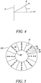
- Figure 4 also refers to Equation 1.
- Figure 4 shows an effective area A.
- the effective area A may be region within a lateral plane in an annulus.
- a dashed line 42 normal to the effective area A indicates a longitudinal direction through the annulus.
- An arrow 41 represents a flow vector for mass flow through the effective area A.
- a swirl angle ⁇ is the angle between the longitudinal direction through the annulus (dashed line 42) and the flow vector (arrow 41).
- the present disclosure may reduce uncertainty of in-flight derived thrust during flight testing.
- fluid (mass) flow derivation is carried out individually for all of the stream tubes in the common measurement plane.
- the overall fluid (mass) flow through the passage e.g. within the bypass duct of a gas turbine engine, is the spatial sum of the individual stream tube fluid (mass) flows.
- an estimate of fluid (mass or volume) flow may be derived in the engine environment, based on measurements, and without relying on an assumed nozzle discharge coefficient of uncertain accuracy.
- the estimated fluid (mass or volume) flow derived in the engine environment in flight may be used to derive an in-flight estimate of the nozzle discharge coefficient.
- the in-flight estimate of the nozzle discharge coefficient may be compared with the assumed value (e.g. sea level static test result) to identify a difference.
- the difference between the in-flight estimate of the nozzle discharge coefficient and the assumed value experimentally provides within tolerance an estimate of the effects of wing-engine interaction. Otherwise, the effects of wing-engine interaction are estimated using analytical methods.
- both derived fluid (mass or volume) flow and jet velocity, which are used for the estimation of in-flight thrust, are estimated on the basis of a nozzle discharge coefficient, which is derived by other means outside the engine environment and without the engine manufacturer being accountable or involved. Accordingly, the accuracy of any derived estimate of fluid (mass or volume) flow will be uncertain.
- Figure 10 illustrates a control system 100 for an aircraft.
- the control system 100 provides a modified primary control parameter 105 for the aircraft.
- the control system 100 includes a primary control parameter leg and a primary control parameter compensation leg.
- an aircraft signal 101 say from an aircraft sensor monitoring operation of the aircraft, causes a pilot or autopilot to implement a thrust demand 102 for the aircraft's engine(s) to deliver increased or decreased thrust.
- the thrust demand 102 generates a demand in the primary control parameter 103.
- a detected change 107 in absolute levels and/or spatial distribution of swirl angle and/or fan pressure at a primary control parameter relative to a reference is detected.
- Deriving, and hence detecting any change in absolute levels and/or spatial distributions of , swirl angle and/or fan pressure may include making use of an estimated flow of a fluid through the bypass duct of the aircraft's engine(s), e.g. produced using a method disclosed herein such as the method of Figure 9 and/or by using an apparatus disclosed herein such as the apparatus of any one of Figures 5 , 6 , 7 or 8 .
- the detected change 107 (e.g. in swirl angle or fan pressure distribution) is then converted into a change to the primary control parameter 106.
- the primary control parameter leg and the primary control compensation leg both feed into a processor 104.
- the processor 104 receives the demand in the primary control parameter 103 output from the primary control parameter leg and the change to the primary control parameter 106 output from the primary control parameter compensation leg.
- the processor 104 compares the demand in the primary control parameter 103 from the primary control parameter leg and the change to the primary control parameter 106 output from the primary control parameter compensation leg and generates a modified primary control parameter 105.
- Figure 11 shows an example of an aircraft 110, which may be a flight test aircraft.
- the aircraft 110 comprises a fuselage 111.
- a first wing 112 extends from one side of the fuselage 111 and a second wing 113 extends from the other side of the fuselage 111.
- the first wing 112 has a first engine 114 mounted thereunder.
- the second wing 113 has a second engine 115 mounted thereunder.
- the first engine 114 and the second engine 115 are gas turbine engines.
- the first engine 114 and the second engine 115 comprise apparatus as described herein, e.g. as illustrated in Figures 5 , 6 , 7 or 8 , for estimating the flow of air through the bypass duct.
- an estimate of the flow of air through the bypass duct may be obtained based on measurements made by instruments located within a common measurement plane within the bypass duct.
- Operation of the aircraft 110 may include use of a control system that makes use of the estimated flow of air through the bypass duct, and/or the distribution of swirl flow angle or pressure, to provide a modified primary control parameter to the aircraft.
- An example control system was described herein in relation to Figure 10 .
- the aircraft may comprise a different number and arrangement of engines from that described in relation to the example shown in Figure 11 .
- the present disclosure can be used to estimate fluid flow through an annulus, e.g. an annulus having strong non-uniform profiles in pressure and/or temperature.
- an annulus e.g. an annulus having strong non-uniform profiles in pressure and/or temperature.
- the present disclosure may be employed in a cold section or a hot section of an aerospace, marine or industrial gas turbine engine.
- the present disclosure may be applied to an electrically driven aircraft propulsor, such as a motor driven ducted fan.
Landscapes
- Engineering & Computer Science (AREA)
- Chemical & Material Sciences (AREA)
- Combustion & Propulsion (AREA)
- Aviation & Aerospace Engineering (AREA)
- Physics & Mathematics (AREA)
- General Physics & Mathematics (AREA)
- Mechanical Engineering (AREA)
- General Engineering & Computer Science (AREA)
- Manufacturing & Machinery (AREA)
- Transportation (AREA)
- Measuring Volume Flow (AREA)
- Structures Of Non-Positive Displacement Pumps (AREA)
Abstract
Description
- The present disclosure concerns a control system for an aircraft, use of such a control system to control operation of an aircraft and a method of operating an aircraft.
- A first aspect provides a control system operable to provide a modified primary control parameter for an aircraft, the control system comprising:
- a primary control parameter leg configured to output a demand in a primary control parameter of the aircraft;
- a primary control parameter compensation leg configured to receive a detected change in absolute levels and/or spatial distributions of swirl angle and/or fan pressure at a primary control parameter relative to a reference and convert the detected change into a change to the primary control parameter; and
- a processor adapted to:
- receive the demand in the primary control parameter output from the primary control parameter leg and the change to the primary control parameter output from the primary control parameter compensation leg;
- compare the demand in the primary control parameter output from the primary control parameter leg and the change to the primary control parameter output from the primary control parameter compensation leg; and
- generate a modified primary control parameter for the aircraft.
- In the primary control parameter leg, an aircraft signal, say from an aircraft sensor monitoring operation of the aircraft, may cause a pilot or autopilot to implement a thrust demand for the aircraft's engine(s) to deliver increased or decreased thrust. The thrust demand may generate the demand in the primary control parameter.
- Deriving, and hence detecting any change in absolute levels and/or spatial distributions of swirl angle and/or fan pressure, may comprise tracking or detecting a change or changes in absolute levels and/or spatial distributions, e.g. radial and/or circumferential distribution, of measured values of one or more properties of a fluid flowing in a bypass duct of the aircraft's engine(s).
- Deriving, and hence detecting any change in absolute levels and/or spatial distributions of swirl angle and/or fan pressure, may comprise tracking or detecting a change or changes in absolute levels and/or spatial distributions, e.g. radial and/or circumferential distribution, of derived values of a parameter of a fluid flowing in a bypass duct of the aircraft's engine(s).
- Deriving, and hence detecting any change in absolute levels and/or spatial distributions of swirl angle and/or fan pressure, may include making use of an estimate of a parameter of a fluid flowing in a bypass duct of the aircraft's engine(s).
- The aircraft's engine(s) may comprise one or more gas turbine engines.
- Alternatively, or in addition, the aircraft's engine(s) may comprise one or more electrically driven fans.
- A method of estimating a parameter of a fluid flowing in the bypass duct may comprise:
- providing a plurality of instruments operable to measure one or more properties of the fluid flowing in the bypass duct, the plurality of instruments being disposed in the bypass duct and arranged within a common measurement plane;
- assigning a stream tube to each instrument, wherein each stream tube represents a region of space in the common measurement plane within the bypass duct and each stream tube surrounds one of the plurality of instruments, wherein the stream tubes together correspond to the cross-sectional shape and area of the bypass duct in the common measurement plane;
- measuring the one or more properties of the fluid using the instruments to obtain one or more measured values for each stream tube;
- using the measured value(s) for each stream tube to calculate a derived value for each stream tube; and
- summing the derived values across all of the stream tubes.
- The fluid may comprise air.
- The common measurement plane may be at an angle to a longitudinal axis of the bypass duct. For instance, the common measurement plane may be at an angle of up to or at least 20°, up to or at least 30°, up to or at least 45°, up to or at least 60°, up to or at least 75° and/or up to 90° to the longitudinal axis of the bypass duct. The common measurement plane may be perpendicular to the longitudinal axis of the bypass duct.
- The plurality of instruments may be located within the bypass duct downstream of a propulsive fan. The plurality of instruments may be located within the bypass duct upstream of a cold nozzle. The plurality of instruments may be located in the region of one or more outlet guide vanes within the bypass duct. Each outlet guide vane may comprise a leading edge and a trailing edge. The plurality of instruments may be disposed in the vicinity of, or upstream of, the leading edge of at least one outlet guide vane. The plurality of instruments may be disposed in the vicinity of, or downstream of, the trailing edge of at least one outlet guide vane. The plurality of instruments may be disposed between the leading edge(s) and the trailing edge(s) of the outlet guide vane(s).
- The common measurement plane may be located within the bypass duct downstream of a propulsive fan. The common measurement plane may be located within the bypass duct upstream of a cold nozzle. The common measurement plane may be located in the region of one or more outlet guide vanes within the bypass duct. Each outlet guide vane may comprise a leading edge and a trailing edge. The common measurement plane may be disposed in the vicinity of, or upstream of, the leading edge of at least one outlet guide vane. The common measurement plane may be disposed in the vicinity of, or downstream of, the trailing edge of at least one outlet guide vane. The common measurement plane may be disposed between the leading edge(s) and the trailing edge(s) of the outlet guide vane(s).
- The plurality of instruments may be arranged within the common measurement plane in a regular or an irregular pattern.
- The regular pattern may comprise one or more lines of symmetry. The regular pattern may have two-or-higher-fold rotational symmetry. The regular pattern may have twofold, three-fold, four-fold, five-fold, six-fold, seven-fold, eight-fold, nine-fold, 10-fold, 11-fold or 12-fold rotational symmetry.
- The plurality of instruments may be arranged in one or more rings, each ring comprising a plurality of spaced-apart, e.g. regularly or irregularly spaced-apart, instruments. The plurality of instruments may be arranged in a plurality of rings. The plurality of rings may be concentric. In each of the rings, e.g. concentric rings, the circumferential spacing between the instruments may be the same or may vary.
- The plurality of instruments may be spaced at intervals, e.g. regularly or irregularly spaced, in a circumferential direction and/or in a radial direction.
- The property of the fluid measured by the plurality of instruments may include one or more of: pressure, e.g. static pressure or total pressure, temperature, fluid flow velocity, fluid flow speed and/or fluid flow direction, e.g. yaw angle of flow.
- Each instrument may comprise a pressure sensor. Each instrument may include a sensor operable to measure or derive fluid flow velocity such as a Pitot tube, or a yaw probe.
- Each instrument may comprise a sensor operable to measure or derive the direction of airflow, in addition to total and static pressure. Each instrument may comprise a yaw probe.
- Summing the derived values across all of the stream tubes may include integrating the derived values across all of the stream tubes.
- The derived value for each stream tube may comprise a derived fluid (mass or volume) flow value. The derived value for each stream tube may comprise a derived thrust value. The derived value for each stream tube may comprise a derived enthalpy value.
- The derived value for each stream tube may constitute an estimate.
- The parameter of the fluid flowing in the bypass duct may comprise fluid (mass or volume) flow. The parameter of the fluid flowing in the bypass duct may comprise thrust, e.g. gross thrust or ideal gross thrust. In embodiments where the instruments are operable to measure temperature, the parameter of the fluid flowing in the bypass duct may comprise enthalpy.
- By using the measured value for each stream tube to calculate a derived value for each stream tube before summing the derived values across all of the stream tubes, a more accurate estimate of the parameter of the fluid flowing in the bypass duct may be obtained.
- The stream tubes may all have the same shape or may have one or more different shapes in cross-section within the common measurement plane.
- Each stream tube may have an annular sector shape in cross-section within the common measurement plane.
- Estimating a parameter of a fluid flowing in the bypass duct may comprise using an apparatus comprising:
a plurality of instruments operable to measure a property of the fluid flowing in the bypass duct, the plurality of instruments being disposed in the bypass duct and arranged within a common measurement plane. - The common measurement plane may be at an angle to a longitudinal axis of the bypass duct. For instance, the common measurement plane may be at an angle of up to or at least 20°, up to or at least 30°, up to or at least 45°, up to or at least 60°, up to or at least 75° and/or up to 90° to the longitudinal axis of the bypass duct. The common measurement plane may be perpendicular to the longitudinal axis of the bypass duct.
- The plurality of instruments may be located within the bypass duct downstream of a propulsive fan. The plurality of instruments may be located within the bypass duct upstream of a cold nozzle. The plurality of instruments may be located in the region of one or more outlet guide vanes within the bypass duct. Each outlet guide vane may comprise a leading edge and a trailing edge. The plurality of instruments may be disposed in the vicinity of, or upstream of, the leading edge of at least one outlet guide vane. The plurality of instruments may be disposed in the vicinity of, or downstream of, the trailing edge of at least one outlet guide vane. The plurality of instruments may be disposed between the leading edge(s) and the trailing edge(s) of the outlet guide vane(s).
- The common measurement plane may be located within the bypass duct downstream of a propulsive fan. The common measurement plane may be located within the bypass duct upstream of a cold nozzle. The common measurement plane may be located in the region of one or more outlet guide vanes within the bypass duct. Each outlet guide vane may comprise a leading edge and a trailing edge. The common measurement plane may be disposed in the vicinity of, or upstream of, the leading edge of at least one outlet guide vane. The common measurement plane may be disposed in the vicinity of, or downstream of, the trailing edge of at least one outlet guide vane. The common measurement plane may be disposed between the leading edge(s) and the trailing edge(s) of the outlet guide vane(s).
- The plurality of instruments may be arranged within the common measurement plane in a regular or an irregular pattern.
- The regular pattern may comprise one or more lines of symmetry. The regular pattern may have two-or-higher-fold rotational symmetry. The regular pattern may have twofold, three-fold, four-fold, five-fold, six-fold, seven-fold, eight-fold, nine-fold, 10-fold, 11-fold or 12-fold rotational symmetry.
- The plurality of instruments may be arranged in one or more rings, each ring comprising a plurality of spaced-apart, e.g. regularly or irregularly spaced-apart, instruments. The plurality of instruments may be arranged in a plurality of rings. The plurality of rings may be concentric. In each of the rings, e.g. concentric rings, the circumferential spacing between the instruments may be the same.
- The plurality of instruments may be spaced at intervals, e.g. regularly or irregularly spaced, in a circumferential direction and/or in a radial direction.
- The property of the fluid measured by the plurality of instruments may include one or more of: pressure, e.g. static pressure or total pressure, temperature, fluid flow velocity, fluid flow speed and/or fluid flow direction, e.g. yaw angle of flow.
- Each instrument may comprise a pressure sensor. Each instrument may include a sensor operable to measure or derive fluid flow velocity such as a Pitot tube, or a yaw probe.
- Each instrument may comprise a sensor operable to measure or derive the direction of airflow, in addition to total and static pressure. Each instrument may comprise a yaw probe.
- The apparatus may comprise one or more data storage devices, e.g. a data logger, adapted to store the measured values measured by the instruments and/or the derived values calculated using the measured values. The data storage device(s) may be adapted to store the measured values and/or the derived values permanently or temporarily.
- The plurality of instruments or the one or more data storage devices may be coupled to a data transmission device for transmitting the measured values to a computer or other data processing device.
- Estimating a parameter of a fluid flowing in the bypass duct may comprise using a system comprising:
- an apparatus as described above; and
- a computer adapted to communicate with the plurality of instruments and to:
- receive measured values of the property of the fluid measured by the plurality of instruments;
- assign a stream tube to each instrument, wherein each stream tube represents a region of space in the common measurement plane within the bypass duct and each stream tube surrounds one of the plurality of instruments, wherein the stream tubes together correspond to the cross-sectional shape and area of the bypass duct in the common measurement plane;
- use the measured value(s) for each stream tube to calculate a derived value for each stream tube;
- sum the derived values across all of the stream tubes.
- Measured values measured by the plurality of instruments may be communicated to the computer in real-time or near-real-time.
- The computer may be located remotely from the plurality of instruments.
- The measured values may be communicated continuously, intermittently or periodically, e.g. at regular intervals.
- The computer may be further adapted to generate an estimate of the parameter of the fluid flowing in the bypass duct.
- The derived value for each stream tube may comprise a derived fluid (mass or volume) flow value. The derived value for each stream tube may comprise a derived thrust value. The derived value for each stream tube may comprise a derived enthalpy value.
- The derived value for each stream tube may constitute an estimate.
- The parameter of the fluid flowing in the bypass duct may comprise fluid (mass or volume) flow. The parameter of the fluid flowing in the bypass duct may comprise thrust, e.g. gross thrust or ideal gross thrust. In embodiments where the instruments are operable to measure temperature, the parameter of the fluid flowing in the bypass duct may comprise enthalpy.
- The computer may be adapted to provide an estimate of in-flight thrust.
- A second aspect provides a gas turbine engine or an aircraft comprising a control system according to the first aspect.
- A third aspect provides a method of operating an aircraft comprising:
- providing a demand in a primary control parameter of the aircraft;
- receiving a detected change in absolute levels and/or spatial distributions of swirl angle and/or fan pressure at a primary control parameter relative to a reference;
- converting the detected change into a change to the primary control parameter;
- comparing the demand in the primary control parameter and the change to the primary control parameter; and
- generating a modified primary control parameter for the aircraft.
- An aircraft signal, say from an aircraft sensor monitoring operation of the aircraft, may cause a pilot or autopilot to implement a thrust demand for the aircraft's engine(s) to deliver increased or decreased thrust. The thrust demand may generate the demand in the primary control parameter.
- Deriving, and hence detecting any change in absolute levels and/or spatial distributions of swirl angle and/or fan pressure, may comprise tracking or detecting a change or changes in absolute levels and/or spatial distributions, e.g. radial and/or circumferential distribution, of measured values of one or more properties of a fluid flowing in a bypass duct of the aircraft's engine(s).
- Deriving, and hence detecting any change in absolute levels and/or spatial distributions of swirl angle and/or fan pressure, may comprise tracking or detecting a change or changes in absolute levels or spatial distributions, e.g. radial and/or circumferential distribution, of derived values of a parameter of a fluid flowing in the bypass duct of the aircraft's engine(s).
- Deriving, and hence detecting any change in absolute levels and/or spatial distributions of swirl angle and/or fan pressure, may include making use of an estimate of a parameter of a fluid flowing in the bypass duct of the aircraft's engine(s).
- The aircraft's engine(s) may comprise one or more gas turbine engines.
- Estimating the parameter of the fluid, e.g. air, flowing in the bypass duct may be done using a method, apparatus or system disclosed herein.
- The method may be performed using a system according to the first aspect.
- The skilled person will appreciate that except where mutually exclusive, a feature described in relation to any one of the above aspects may be applied mutatis mutandis to any other aspect. Furthermore except where mutually exclusive any feature described herein may be applied to any aspect and/or combined with any other feature described herein.
- Embodiments will now be described by way of example only, with reference to the Figures, in which:
-
Figure 1 is a sectional side view of a gas turbine engine; -
Figure 2 is a schematic cross-sectional view of a front portion of a gas turbine engine; -
Figure 3 is a cross-section of an outlet guide vane; -
Figure 4 illustrates a swirl angle; -
Figure 5 shows a bypass duct in lateral cross-section at a position in the vicinity of the leading edges of the outlet guide vanes; -
Figure 6 illustrates stream tubes applied to the same cross-section asFigure 5 ; -
Figure 7 is a schematic longitudinal cross-sectional view of a portion a bypass duct with an apparatus for estimating flow of a fluid through an annulus disposed therein; -
Figure 8 is a schematic longitudinal cross-sectional view of a portion of a bypass duct with another apparatus for estimating flow of a fluid through an annulus disposed therein; -
Figure 9 is a flow chart illustrating a method of estimating flow of a fluid through an annulus; -
Figure 10 illustrates the operation of a control system for an aircraft, the control system being operable to provide a modified primary control parameter for the aircraft; and -
Figure 11 is a schematic illustration of an example of an aircraft, to which the methods and apparatuses of the present disclosure may be applied. - In the Figures, like reference numerals are used for like components.
- With reference to
Figure 1 , a gas turbine engine is generally indicated at 10, having a principal androtational axis 11. Theengine 10 comprises, in axial flow series, anair intake 12, apropulsive fan 13, anintermediate pressure compressor 14, a high-pressure compressor 15,combustion equipment 16, a high-pressure turbine 17, anintermediate pressure turbine 18, a low-pressure turbine 19 and anexhaust nozzle 20. Anacelle 21 generally surrounds theengine 10 and defines both theintake 12 and theexhaust nozzle 20. - The
gas turbine engine 10 works in the conventional manner so that air entering theintake 12 is accelerated by thefan 13 to produce two air flows: a first air flow into theintermediate pressure compressor 14 and a second air flow which passes through abypass duct 22 to provide propulsive thrust. Theintermediate pressure compressor 14 compresses the air flow directed into it before delivering that air to thehigh pressure compressor 15 where further compression takes place. - The compressed air exhausted from the high-
pressure compressor 15 is directed into thecombustion equipment 16 where it is mixed with fuel and the mixture combusted. The resultant hot combustion products then expand through, and thereby drive, the high, intermediate and low-pressure turbines nozzle 20 to provide additional propulsive thrust. The high 17, intermediate 18 and low 19 pressure turbines drive respectively thehigh pressure compressor 15,intermediate pressure compressor 14 andfan 13, each by a suitable interconnecting shaft. - In the
bypass duct 22, downstream of thefan 13, there is a plurality of outlet guide vanes 23. Theoutlet guide vanes 23 are spaced at intervals circumferentially. Thebypass duct 22 terminates at its downstream end at acold nozzle 25. Thecold nozzle 25 forms an annulus around ahot nozzle 24. Hot combustion products pass through thehot nozzle 24 after having driven thelow pressure turbine 19. Thecold nozzle 25 and thehot nozzle 24 communicate with theexhaust nozzle 20. - Other gas turbine engines to which the present disclosure may be applied may have alternative configurations. By way of example such engines may have an alternative number of interconnecting shafts (e.g. two) and/or an alternative number of compressors and/or turbines. Further the engine may comprise a gearbox provided in the drive train from a turbine to a compressor and/or fan.
-
Figure 2 shows schematically a front portion of thegas turbine engine 10, magnified relative toFigure 1 . Only one side of theprincipal axis 11 is shown for clarity, although it will be understood that the other side of theprincipal axis 11 may be generally the same as the side shown. Theair intake 12 is upstream of thepropulsive fan 13. In thebypass duct 22 downstream of thepropulsive fan 13 there is a plurality of outlet guide vanes 23. -
Figure 3 shows one of theoutlet guide vanes 23 in schematic cross-section. Theoutlet guide vane 23 has an aerofoil shape. Theoutlet guide vane 23 has twoaxial sides leading edge 233 and a trailingedge 234. -
Figure 5 shows thebypass duct 22 in lateral cross-section at a position in the vicinity of the leading edges of the outlet guide vanes 23. Thebypass duct 22 has the form of an annulus and is defined by aninner wall 221 and anouter wall 222. At a regular circumferential spacing, a plurality ofoutlet guide vanes 23 each extend radially from theinner wall 221 to theouter wall 222. - As illustrated, there are 16
outlet guide vanes 23, which are regularly spaced circumferentially around thebypass duct 22. In embodiments, the plurality of outlet guide vanes may comprise a different number of outlet guide vanes. The circumferential spacing between the outlet guide vanes may not be regular. - An apparatus for estimating a parameter, e.g. (mass or volume) flow, of a fluid flowing in a passage is disposed in the
bypass duct 22. The apparatus comprises a plurality ofsensors 50. Foursensors 50 are disposed at the leading edge of every secondoutlet guide vane 23. Thesensors 50 are spaced at intervals, which may be regular or irregular intervals, along the leading edge of every secondoutlet guide vane 23. Thus, in the illustrated example, foursensors 50 are disposed on eight of the 16 outlet guide vanes 23. Consequently, there is a regular pattern of 32sensors 50 in a common measurement plane in the vicinity of the leading edges of the outlet guide vanes 23. The common measurement plane may coincide with the leading edges of the outlet guide vanes 23. The number and arrangement of thesensors 50 may vary. For instance, there may be more than or fewer than foursensors 50 disposed at the leading edge of every secondoutlet guide vane 23. Thesensors 50 may be disposed at the leading edges of more than or less than half of the total number of outlet guide vanes 23. - The common measurement plane may be at any axial location within the
bypass duct 22. - Each
sensor 50 is operable to measure or derive the direction of airflow. Eachsensor 50 may comprise a yaw probe. -
Figure 6 shows the same cross-section of thebypass duct 22 as inFigure 5 . Like features are labelled with like reference numerals. For clarity, only theoutlet guide vanes 23 withsensors 50 disposed at their leading edges are shown. The common measurement plane is divided into 32stream tubes 60, as indicated by the dashed lines. Eachstream tube 60 represents a region of space in the common measurement plane. Eachstream tube 60 has the shape of an annular sector. Eachstream tube 60 includes onesensor 50 at a central location therein. The number, arrangement and shape ofstream tubes 60 may vary depending on the number and arrangement of sensors in the common measurement plane. -
Figure 7 is a schematic longitudinal cross-sectional view of a portion of thebypass duct 22, including the apparatus shown inFigures 5 and6 . Theprincipal axis 11 of the gas turbine engine is indicated by a dashed line. Thepropulsive fan 13 comprises a plurality offan rotor blades 131. Three of thefan rotor blades 131 are shown inFigure 6 . Thefan rotor blades 131 rotate in the direction indicated byarrow 70. Three of theoutlet guide vanes 23 are shown inFigure 7 . Asensor 50, which may comprise a yaw probe, is disposed at theleading edge 233 of one of the outlet guide vanes 23. - Three vectors are also shown in
Figure 7 . A first vector u represents the circumferential velocity due to rotation of thepropulsive fan 13. A second vector w represents the relative velocity of the air flow observed by the rotating fan blade. A third vector v represents the actual velocity vector observed by the fan outlet guide vanes 23. - Measurements from the yaw tubes disposed at the leading edges of (at least some of) the fan outlet guide vanes may be used to derive values of total pressure, static pressure and swirl angle for each stream tube. Deriving a value for the swirl angle for each stream tube may provide information on the angle of incidence of the fluid flow with the outlet guide vanes and hence pressure loss.
-
Figure 8 is a schematic longitudinal cross-sectional view of a portion of thebypass duct 22, including another embodiment of an apparatus for estimating a parameter, e.g. (mass or volume) flow, of a fluid flowing in a passage. As inFigure 7 , theprincipal axis 11 of the gas turbine engine is indicated by a dashed line. Thepropulsive fan 13 comprises a plurality offan rotor blades 131. Three of thefan rotor blades 131 are shown inFigure 8 . Thefan rotor blades 131 rotate in the direction indicated byarrow 70. Three of theoutlet guide vanes 23 are shown inFigure 8 . - A plurality of
sensors 80 are arranged in a common measurement plane a short distance downstream of the trailingedges 234 of the outlet guide vanes 23. Two of thesensors 80 are shown inFigure 8 . Thesensors 80 are disposed such that they are each aligned longitudinally with a central part of a gap between a pair of adjacent outlet guide vanes 23. The plurality ofsensors 80 may be arranged in a regular or irregular pattern within the common measurement plane. Eachsensor 80 may comprise a pressure measurement instrument operable to measure fluid flow velocity such as a Pitot tube. Eachsensor 80 may comprise a yaw tube. A stream tube may be associated with eachsensor 80. - Three vectors are also shown in
Figure 8 . A first vector u represents the circumferential velocity due to rotation of thepropulsive fan 13. A second vector w represents the relative velocity of the air flow observed by the fan rotor blade. A third vector v represents the actual velocity vector observed by the fan outlet guide vanes 23. - The
sensors 80 may be located downstream of theoutlet guide vanes 23 at positions where fluid flow may be or may not be disturbed by wakes from the outlet guide vanes 23. Thesensors 80 may comprise Pitot tubes or yaw probes, which may be operable to measure total and static pressure. The swirl angle may be assumed to be close to the outlet guide vane outlet angle. - The apparatuses for estimating a parameter of a fluid flowing in a passage may comprise sensors operable to measure more than one property of the fluid flowing in the passage. Fluid properties that may be measured may include: pressure, e.g. total pressure or static pressure, temperature, fluid flow velocity, fluid flow speed and/or fluid flow direction, e.g. yaw angle of flow.
- Measured values for each stream tube measured by the
sensors sensors - The processor or computer is configured to use the measured value(s) for each stream tube to calculate a derived value for each stream tube. The processor is configured to sum the derived values across all of the stream tubes. The computer is configured to generate an estimate of the parameter of the fluid flowing in the passage based on the sum of the derived values across all of the stream tubes
The parameter may be fluid (mass or volume) flow. The estimate of fluid flow through the passage, e.g. bypass duct, may be used to provide an estimate of in-flight thrust. - By taking many simultaneous measurements of one or more properties of the fluid flowing in the passage, e.g. bypass duct, good coverage and/or reduced sampling error may be achieved.
- The present disclosure may reduce uncertainty of in-flight derived thrust during flight testing.
- The plurality of instruments in the common measurement plane may provide simultaneous multiple readings of one or more properties of the fluid flowing in the passage. The one or more properties, e.g. pressure, are measured at specific radial and circumferential positions within the common measurement plane.
- By positioning the common measurement plane in the vicinity of, or downstream of, the outlet guide vane(s) in the bypass duct, a more accurate estimate of fluid (mass or volume) flow may be derivable. The derived estimate of fluid (mass or volume) flow may be more accurate than can be obtained using known methods such as: (i) a derived fluid (mass) flow estimate based on intake pressure measurements, as this may be inaccurate due to uncertainty in the assumed intake effective area and/or the assumed intake discharge coefficient; or (ii) a derived fluid (mass) flow estimate based on nozzle performance, as this may be inaccurate due to uncertainty in the assumed nozzle discharge coefficient.
-
Figure 9 illustrates a method of estimating a parameter of a fluid flowing in a passage such as a bypass duct of a gas turbine engine. - A
first step 91 comprises providing a plurality of instruments operable to measure one or more properties of the fluid flowing in the passage, the plurality of instruments being disposed in the annulus and arranged within a common measurement plane. The common measurement plane may be at an angle to a longitudinal axis of the passage. - In a
second step 92, a stream tube is assigned to each instrument. Each stream tube represents a region of space in the common measurement plane within the passage and each stream tube surrounds one of the plurality of instruments. The stream tubes together correspond to the cross-sectional shape and area of the passage in the common measurement plane. - A
third step 93 comprises measuring the one or more properties of the fluid using the instruments to obtain one or more measured values for each stream tube. - A
fourth step 94 comprises using the measured value(s) for each stream tube to calculate a derived value for each stream tube. - A
fifth step 95 comprises summing the derived values across all of the stream tubes. - A formula for estimating mass flow in an annulus from measurements of static pressure and total pressure is given by Equation 1 below.

- Ps = static pressure
- Pt = total pressure
- W = mass-flow
- γ = ratio of specific heats, a gas property that is an explicit function of temperature and chemical composition; for the derivation of the equation above it is considered constant. For air γ ≈ 1.4 is a very good approximation in the bypass duct.
- R = gas constant
- Tt = total temperature
- A = area
-
Figure 4 also refers to Equation 1.Figure 4 shows an effective area A. The effective area A may be region within a lateral plane in an annulus. A dashedline 42 normal to the effective area A indicates a longitudinal direction through the annulus. Anarrow 41 represents a flow vector for mass flow through the effective area A. A swirl angle α is the angle between the longitudinal direction through the annulus (dashed line 42) and the flow vector (arrow 41). - The present disclosure may reduce uncertainty of in-flight derived thrust during flight testing.
- In the present disclosure, it will be noted that averaging of measured quantities is not carried out before the estimation of fluid (mass) flow, as per typical known zero-dimensional fluid (mass) flow derivations. In the present disclosure, fluid (mass) flow derivation is carried out individually for all of the stream tubes in the common measurement plane. The overall fluid (mass) flow through the passage, e.g. within the bypass duct of a gas turbine engine, is the spatial sum of the individual stream tube fluid (mass) flows.
- In accordance with the present disclosure, an estimate of fluid (mass or volume) flow may be derived in the engine environment, based on measurements, and without relying on an assumed nozzle discharge coefficient of uncertain accuracy.
- The estimated fluid (mass or volume) flow derived in the engine environment in flight, e.g. during a flight test, may be used to derive an in-flight estimate of the nozzle discharge coefficient. The in-flight estimate of the nozzle discharge coefficient may be compared with the assumed value (e.g. sea level static test result) to identify a difference. The difference between the in-flight estimate of the nozzle discharge coefficient and the assumed value experimentally provides within tolerance an estimate of the effects of wing-engine interaction. Otherwise, the effects of wing-engine interaction are estimated using analytical methods.
- By way of comparison, it is known to derive in-flight thrust based on derivation of fluid (mass) flow and jet velocity assuming:
- cold nozzle performance, i.e. discharge and velocity coefficients;
- a series of total pressure measurements, which are averaged and corrected for position to derive total pressure at the cold nozzle plane;
- the ratio of total pressure at nozzle plane to ambient or base pressure provides Mach number at nozzle plane;
- assumed fan efficiency provides an estimate of temperature, which in conjunction with the Mach number above provide exhaust jet velocity;
- jet velocity and the effective nozzle area (effective area being the geometric nozzle area multiplied by the assumed nozzle discharge coefficient) are used to estimate fluid volume flow (WTAP);
- knowledge of absolute averaged total pressure and temperature are used to derive fluid mass flow (W) from fluid volume flow (WTAP);
- fluid mass flow and jet velocity estimated as described above and the assumed nozzle velocity coefficient together provide an estimate of gross thrust.
- In effect, in known methods, both derived fluid (mass or volume) flow and jet velocity, which are used for the estimation of in-flight thrust, are estimated on the basis of a nozzle discharge coefficient, which is derived by other means outside the engine environment and without the engine manufacturer being accountable or involved. Accordingly, the accuracy of any derived estimate of fluid (mass or volume) flow will be uncertain.
-
Figure 10 illustrates acontrol system 100 for an aircraft. Thecontrol system 100 provides a modifiedprimary control parameter 105 for the aircraft. - The
control system 100 includes a primary control parameter leg and a primary control parameter compensation leg. - In the primary control parameter leg, an
aircraft signal 101, say from an aircraft sensor monitoring operation of the aircraft, causes a pilot or autopilot to implement athrust demand 102 for the aircraft's engine(s) to deliver increased or decreased thrust. Thethrust demand 102 generates a demand in theprimary control parameter 103. - In the primary control parameter compensation leg, a detected
change 107 in absolute levels and/or spatial distribution of swirl angle and/or fan pressure at a primary control parameter relative to a reference is detected. Deriving, and hence detecting any change in absolute levels and/or spatial distributions of , swirl angle and/or fan pressure may include making use of an estimated flow of a fluid through the bypass duct of the aircraft's engine(s), e.g. produced using a method disclosed herein such as the method ofFigure 9 and/or by using an apparatus disclosed herein such as the apparatus of any one ofFigures 5 ,6 ,7 or8 . - In the primary control parameter compensation leg, the detected change 107 (e.g. in swirl angle or fan pressure distribution) is then converted into a change to the
primary control parameter 106. - The primary control parameter leg and the primary control compensation leg both feed into a
processor 104. Theprocessor 104 receives the demand in theprimary control parameter 103 output from the primary control parameter leg and the change to theprimary control parameter 106 output from the primary control parameter compensation leg. - The
processor 104 compares the demand in theprimary control parameter 103 from the primary control parameter leg and the change to theprimary control parameter 106 output from the primary control parameter compensation leg and generates a modifiedprimary control parameter 105. -
Figure 11 shows an example of anaircraft 110, which may be a flight test aircraft. Theaircraft 110 comprises afuselage 111. Afirst wing 112 extends from one side of thefuselage 111 and asecond wing 113 extends from the other side of thefuselage 111. Thefirst wing 112 has afirst engine 114 mounted thereunder. Thesecond wing 113 has asecond engine 115 mounted thereunder. Thefirst engine 114 and thesecond engine 115 are gas turbine engines. Thefirst engine 114 and thesecond engine 115 comprise apparatus as described herein, e.g. as illustrated inFigures 5 ,6 ,7 or8 , for estimating the flow of air through the bypass duct. By practising the methods disclosed herein, an estimate of the flow of air through the bypass duct may be obtained based on measurements made by instruments located within a common measurement plane within the bypass duct. Operation of theaircraft 110 may include use of a control system that makes use of the estimated flow of air through the bypass duct, and/or the distribution of swirl flow angle or pressure, to provide a modified primary control parameter to the aircraft. An example control system was described herein in relation toFigure 10 . - The aircraft may comprise a different number and arrangement of engines from that described in relation to the example shown in
Figure 11 . - The present disclosure can be used to estimate fluid flow through an annulus, e.g. an annulus having strong non-uniform profiles in pressure and/or temperature. Hence, for example, the present disclosure may be employed in a cold section or a hot section of an aerospace, marine or industrial gas turbine engine. Similarly, the present disclosure may be applied to an electrically driven aircraft propulsor, such as a motor driven ducted fan.
- It will be understood that the invention is not limited to the embodiments above-described and various modifications and improvements can be made without departing from the concepts herein. Except where mutually exclusive, any of the features may be employed separately or in combination with any other features and the disclosure extends to and includes all combinations and sub-combinations of one or more features described herein.
Claims (15)
- A control system (100) operable to provide a modified primary control parameter for an aircraft, the control system (100) comprising:a primary control parameter leg configured to output a demand in a primary control parameter (103) of the aircraft;a primary control parameter compensation leg configured to receive a detected change (107) in absolute levels and/or spatial distributions of swirl angle and/or fan pressure at a primary control parameter relative to a reference and convert the detected change (107) into a change to the primary control parameter (106); anda processor adapted to:receive the demand in the primary control parameter (103) output from the primary control parameter leg and the change to the primary control parameter (106) output from the primary control parameter compensation leg;compare the demand in the primary control parameter (103) output from the primary control parameter leg and the change to the primary control parameter (106) output from the primary control parameter compensation leg; andgenerate a modified primary control parameter (105) for the aircraft.
- A control system (100) according to claim 1, wherein a thrust demand (102) generates the demand in the primary control parameter.
- A control system (100) according to claim 1 or claim 2, wherein deriving, and hence detecting any change in absolute levels and/or spatial distributions of swirl angle and/or fan pressure, comprises tracking or detecting a change or changes in absolute levels and/or spatial distributions of measured values of one or more properties of a fluid flowing in a bypass duct of the aircraft's engine(s).
- A control system (100) according to claim 1, claim 2 or claim 3, wherein deriving, and hence detecting any change in absolute levels and/or spatial distributions of swirl angle and/or fan pressure, comprises tracking or detecting a change or changes in absolute levels and/or spatial distributions of derived values of a parameter of a fluid flowing in a bypass duct of the aircraft's engine(s).
- A control system (100) according to any one of claims 1 to 4, wherein deriving, and hence detecting any change in absolute levels and/or spatial distributions of swirl angle and/or fan pressure, includes making use of an estimate of a parameter of a fluid flowing in a bypass duct (22) of the aircraft's engine(s) (10).
- A control system (100) according to any one of the preceding claims, the system comprising an apparatus for estimating a parameter of a fluid flowing in the bypass duct (22), the apparatus comprising:
a plurality of instruments (50; 80) operable to measure one or more properties of the fluid flowing in the bypass duct (22), the plurality of instruments (50; 80) being disposed in the bypass duct (22) and arranged within a common measurement plane. - A control system (100) according to claim 6, wherein the common measurement plane is located within the bypass duct (22) downstream of a propulsive fan (13).
- A control system (100) according to claim 6 or claim 7, wherein the common measurement plane is located in the region of one or more outlet guide vanes (23) within the bypass duct (22).
- A control system (100) according to claim 6, claim 7 or claim 8, wherein the plurality of instruments (50; 80) is arranged within the common measurement plane in a regular or an irregular pattern.
- A control system (100) according to any one of claims 6 to 9, wherein the plurality of instruments (50; 80) is arranged in one or more rings, each ring comprising a plurality of spaced-apart instruments.
- A control system (100) according to any one of claims 6 to 10, wherein the plurality of instruments (50; 80) is spaced at intervals in a circumferential direction and/or in a radial direction.
- A control system (100) according to any one of claims 6 to 11, wherein the one or more properties of the fluid measured by the plurality of instruments include one or more of: pressure, e.g. static pressure or total pressure, temperature, fluid flow velocity, fluid flow speed and/or fluid flow direction, e.g. yaw angle of flow.
- A control system (100) according to any one of claims 6 to 12 comprising:
a computer adapted to communicate with the plurality of instruments (50; 80) and to:receive measured values of the one or more properties of the fluid measured by the plurality of instruments (50; 80);assign a stream tube (60) to each instrument (50; 80), wherein each stream tube (60) represents a region of space in the common measurement plane within the bypass duct (22) and each stream tube (60) surrounds one of the plurality of instruments (50; 80), wherein the stream tubes (60) together correspond to the cross-sectional shape and area of the bypass duct (22) in the common measurement plane;use the measured value(s) for each stream tube (60) to calculate derived value for each stream tube (60);sum the derived values across all of the stream tubes (60). - A gas turbine engine (10) or an aircraft (110) comprising a control system (100) according to any one of claims 1 to 14.
- A method of operating an aircraft (110) comprising:providing a demand in a primary control parameter (103) of the aircraft (110);receiving a detected change (107) in absolute levels and/or spatial distributions of swirl angle and/or fan pressure at a primary control parameter relative to a reference;converting the detected change (107) into a change to the primary control parameter (106);comparing the demand in the primary control parameter (103) and the change to the primary control parameter (106); andgenerating a modified primary control parameter (105) for the aircraft (110).
Applications Claiming Priority (2)
| Application Number | Priority Date | Filing Date | Title |
|---|---|---|---|
| GR20180100267 | 2018-06-20 | ||
| GR20180100268 | 2018-06-20 |
Publications (2)
| Publication Number | Publication Date |
|---|---|
| EP3584428A1 true EP3584428A1 (en) | 2019-12-25 |
| EP3584428B1 EP3584428B1 (en) | 2021-03-31 |
Family
ID=66821027
Family Applications (2)
| Application Number | Title | Priority Date | Filing Date |
|---|---|---|---|
| EP19179303.3A Active EP3584428B1 (en) | 2018-06-20 | 2019-06-11 | Control system for a gas turbine engine |
| EP19179306.6A Not-in-force EP3584557B1 (en) | 2018-06-20 | 2019-06-11 | System and method for estimating an air mass flow of air flowing in a bypass duct of a gas turbine engine |
Family Applications After (1)
| Application Number | Title | Priority Date | Filing Date |
|---|---|---|---|
| EP19179306.6A Not-in-force EP3584557B1 (en) | 2018-06-20 | 2019-06-11 | System and method for estimating an air mass flow of air flowing in a bypass duct of a gas turbine engine |
Country Status (3)
| Country | Link |
|---|---|
| US (2) | US11236683B2 (en) |
| EP (2) | EP3584428B1 (en) |
| CN (2) | CN110615091A (en) |
Families Citing this family (10)
| Publication number | Priority date | Publication date | Assignee | Title |
|---|---|---|---|---|
| US11427353B2 (en) * | 2019-12-13 | 2022-08-30 | Pratt & Whitney Canada Corp. | System and method for testing engine performance in-flight |
| US11796358B2 (en) | 2020-09-10 | 2023-10-24 | Virginia Tech Intellectual Properties, Inc. | Flow measurement for a gas turbine engine |
| US11821771B2 (en) | 2020-09-10 | 2023-11-21 | Virginia Tech Intellectual Properties, Inc. | Flow measurement for a gas turbine engine |
| US11747236B2 (en) | 2020-09-10 | 2023-09-05 | Virginia Tech Intellectual Properties, Inc. | Flow measurement for a gas turbine engine |
| GB202014210D0 (en) * | 2020-09-10 | 2020-10-28 | Rolls Royce Plc | Gas turbine engine with airflow measurement system |
| CN112485013B (en) * | 2020-11-16 | 2021-07-30 | 中国空气动力研究与发展中心高速空气动力研究所 | Single turbofan engine nacelle surface pressure measurement test device with turbine power simulation and pressure measurement test method |
| CN113252351B (en) * | 2021-06-10 | 2021-10-01 | 中国航发上海商用航空发动机制造有限责任公司 | Reduced-scale test piece and method for cutting off outer culvert division wall guide vane |
| US11674450B1 (en) | 2021-12-13 | 2023-06-13 | Pratt & Whitney Canada Corp. | System and method for synthesizing engine thrust |
| CN116499756B (en) * | 2023-05-19 | 2026-04-14 | 中国航发沈阳发动机研究所 | Transient flow measurement method in test flow passage of aero-engine |
| US12584421B2 (en) * | 2023-07-31 | 2026-03-24 | Rolls-Royce North American Technologies Inc. | Heat exchanger with inlet and outlet turning vanes for use in gas turbine engines |
Citations (4)
| Publication number | Priority date | Publication date | Assignee | Title |
|---|---|---|---|---|
| US4248042A (en) * | 1978-11-03 | 1981-02-03 | The Boeing Company | Engine thrust control system |
| GB2252131A (en) * | 1987-11-20 | 1992-07-29 | Secr Defence | Pressure measurement in turbofan engines. |
| EP1178196A2 (en) * | 2000-07-31 | 2002-02-06 | General Electric Company | Methods and apparatus for trimming engine control systems |
| RU2649715C1 (en) * | 2016-12-06 | 2018-04-04 | Федеральное государственное унитарное предприятие "Центральный институт авиационного моторостроения имени П.И. Баранова" | Method of aviation bypass turbojet engine with flows mixing in-flight diagnostics |
Family Cites Families (26)
| Publication number | Priority date | Publication date | Assignee | Title |
|---|---|---|---|---|
| US4050306A (en) * | 1976-02-27 | 1977-09-27 | General Electric Company | Method and apparatus for measuring pressures |
| US4162630A (en) | 1976-09-20 | 1979-07-31 | University Of Utah | Measurement and reconstruction of three-dimensional fluid flow |
| US4967550A (en) * | 1987-04-28 | 1990-11-06 | Rolls-Royce Plc | Active control of unsteady motion phenomena in turbomachinery |
| US5259187A (en) * | 1993-02-05 | 1993-11-09 | General Electric Company | Method of operating an aircraft bypass turbofan engine having variable fan outlet guide vanes |
| GB9918092D0 (en) * | 1999-08-03 | 1999-10-06 | Rolls Royce Plc | Ducted fan gas turbine engine control system |
| US6595062B1 (en) | 2000-10-16 | 2003-07-22 | Lockheed Martin Corporation | High temperature rake for suspersonic flow |
| DE10251701B4 (en) | 2002-11-06 | 2006-05-04 | Siemens Ag | Measuring element for determining a flow velocity |
| DE602004016065D1 (en) * | 2004-12-01 | 2008-10-02 | United Technologies Corp | VARIABLE BULB INLET BUCKET ASSEMBLY, TURBINE ENGINE WITH SUCH AN ARRANGEMENT AND CORRESPONDING STEERING PROCEDURE |
| US7159401B1 (en) | 2004-12-23 | 2007-01-09 | Kulite Semiconductor Products, Inc. | System for detecting and compensating for aerodynamic instabilities in turbo-jet engines |
| GB0510440D0 (en) | 2005-05-21 | 2005-06-29 | Rolls Royce Plc | An instrumentation rake |
| GB2438431B (en) * | 2006-05-25 | 2008-08-20 | Rolls Royce Plc | Thrust correction |
| US7779811B1 (en) * | 2006-09-13 | 2010-08-24 | General Electric Company | Thermoelectrically cooled components for distributed electronics control system for gas turbine engines |
| US8282337B2 (en) | 2007-12-28 | 2012-10-09 | General Electric Company | Instability mitigation system using stator plasma actuators |
| KR101332923B1 (en) | 2009-09-29 | 2013-11-26 | 지멘스 악티엔게젤샤프트 | System for determining exhaust gas volume |
| DE102009043345A1 (en) * | 2009-09-29 | 2011-05-12 | Siemens Aktiengesellschaft | Exhaust gas generating device, in particular ship, with an exhaust volume determination |
| US9556798B2 (en) | 2013-01-28 | 2017-01-31 | General Electric Company | Systems and methods for measuring a flow profile in a turbine engine flow path |
| WO2015142318A1 (en) * | 2014-03-18 | 2015-09-24 | Siemens Aktiengesellschaft | System and method for monitoring air flow into a turbine engine |
| US9334807B2 (en) * | 2014-05-13 | 2016-05-10 | The Boeing Company | Methods and apparatus to determine airflow conditions at an inlet of an engine |
| FR3021741B1 (en) * | 2014-05-27 | 2017-11-24 | Snecma | METHOD FOR MEASURING THE FLOW OF GAS AT THE EXIT OF A TURBOMACHINE COMBUSTION CHAMBER |
| US9957900B2 (en) * | 2015-05-11 | 2018-05-01 | General Electric Company | System and method for flow control in turbine |
| GB2539874A (en) * | 2015-06-22 | 2017-01-04 | Rolls Royce Plc | Aircraft vapour trail control system |
| FR3043775B1 (en) | 2015-11-12 | 2017-11-10 | Snecma | DEVICE FOR MEASURING AERODYNAMIC SIZES FOR PLACING IN A FLOWING VEHIC OF A TURBOMACHINE |
| US11073090B2 (en) * | 2016-03-30 | 2021-07-27 | General Electric Company | Valved airflow passage assembly for adjusting airflow distortion in gas turbine engine |
| US20170342913A1 (en) * | 2016-05-24 | 2017-11-30 | United Technologies Corporation | Gas turbine engine inlet temperature sensor configuration |
| GB201615969D0 (en) * | 2016-09-20 | 2016-11-02 | Rolls Royce Plc | Control system for a cabin blower system |
| CN108116658B (en) * | 2017-12-13 | 2020-04-10 | 哈尔滨工业大学深圳研究生院 | Aircraft control method and system and aircraft |
-
2019
- 2019-05-24 US US16/422,231 patent/US11236683B2/en not_active Expired - Fee Related
- 2019-05-24 US US16/422,334 patent/US11193854B2/en not_active Expired - Fee Related
- 2019-06-11 EP EP19179303.3A patent/EP3584428B1/en active Active
- 2019-06-11 EP EP19179306.6A patent/EP3584557B1/en not_active Not-in-force
- 2019-06-20 CN CN201910539819.8A patent/CN110615091A/en active Pending
- 2019-06-20 CN CN201910536102.8A patent/CN110631837A/en active Pending
Patent Citations (4)
| Publication number | Priority date | Publication date | Assignee | Title |
|---|---|---|---|---|
| US4248042A (en) * | 1978-11-03 | 1981-02-03 | The Boeing Company | Engine thrust control system |
| GB2252131A (en) * | 1987-11-20 | 1992-07-29 | Secr Defence | Pressure measurement in turbofan engines. |
| EP1178196A2 (en) * | 2000-07-31 | 2002-02-06 | General Electric Company | Methods and apparatus for trimming engine control systems |
| RU2649715C1 (en) * | 2016-12-06 | 2018-04-04 | Федеральное государственное унитарное предприятие "Центральный институт авиационного моторостроения имени П.И. Баранова" | Method of aviation bypass turbojet engine with flows mixing in-flight diagnostics |
Also Published As
| Publication number | Publication date |
|---|---|
| US20190391047A1 (en) | 2019-12-26 |
| US20190389566A1 (en) | 2019-12-26 |
| EP3584428B1 (en) | 2021-03-31 |
| CN110615091A (en) | 2019-12-27 |
| CN110631837A (en) | 2019-12-31 |
| EP3584557B1 (en) | 2021-11-24 |
| US11236683B2 (en) | 2022-02-01 |
| US11193854B2 (en) | 2021-12-07 |
| EP3584557A1 (en) | 2019-12-25 |
Similar Documents
| Publication | Publication Date | Title |
|---|---|---|
| US11236683B2 (en) | Control system | |
| US6473705B1 (en) | System and method for direct non-intrusive measurement of corrected airflow | |
| EP3967850B1 (en) | Turbomachine with air flow measurement system | |
| US10371000B1 (en) | Flush-mount combined static pressure and temperature probe | |
| US11815048B2 (en) | Gas turbine engine with airflow measurement system | |
| CN114165296B (en) | Flow measurement for gas turbine engines | |
| US20250043693A1 (en) | In-flight measured propulsion mass flow and thrust on aircraft | |
| EP3967851B1 (en) | Gas turbine engine with air flow measurement system | |
| Meillard et al. | Time resolved pressure and velocity measurements at the DLR UHBR-Fan and comparison with simulation data | |
| Bhatnagar et al. | The Purdue High-Speed Small Core Turbine Facility | |
| Schumann et al. | Effect of area ratio on the performance of a 5.5: 1 pressure ratio centrifugal impeller | |
| US20260078686A1 (en) | In-flight measured propulsion mass flow and thrust on aircraft | |
| Neumayer et al. | Performance testing of a first and a second transonic turbine stage | |
| Standahar et al. | Investigation of a High-pressure-ratio Eight-stage Axial-flow Research Compressor with Two Transonic Inlet Stages V: Preliminary Analysis of Over-all Performance of Modified Compressor | |
| Stephens et al. | Characterization of the Upgraded NASA GRC Single Stage Axial Compressor and Fan Facility | |
| DICICCO et al. | Description of a pressure measurement technique for obtaining surface static pressures of a radial turbine | |
| Adams | Turbomachinery Performance Testing |
Legal Events
| Date | Code | Title | Description |
|---|---|---|---|
| PUAI | Public reference made under article 153(3) epc to a published international application that has entered the european phase |
Free format text: ORIGINAL CODE: 0009012 |
|
| STAA | Information on the status of an ep patent application or granted ep patent |
Free format text: STATUS: THE APPLICATION HAS BEEN PUBLISHED |
|
| AK | Designated contracting states |
Kind code of ref document: A1 Designated state(s): AL AT BE BG CH CY CZ DE DK EE ES FI FR GB GR HR HU IE IS IT LI LT LU LV MC MK MT NL NO PL PT RO RS SE SI SK SM TR |
|
| AX | Request for extension of the european patent |
Extension state: BA ME |
|
| RAP1 | Party data changed (applicant data changed or rights of an application transferred) |
Owner name: ROLLS-ROYCE PLC |
|
| STAA | Information on the status of an ep patent application or granted ep patent |
Free format text: STATUS: REQUEST FOR EXAMINATION WAS MADE |
|
| 17P | Request for examination filed |
Effective date: 20200420 |
|
| RBV | Designated contracting states (corrected) |
Designated state(s): AL AT BE BG CH CY CZ DE DK EE ES FI FR GB GR HR HU IE IS IT LI LT LU LV MC MK MT NL NO PL PT RO RS SE SI SK SM TR |
|
| GRAP | Despatch of communication of intention to grant a patent |
Free format text: ORIGINAL CODE: EPIDOSNIGR1 |
|
| STAA | Information on the status of an ep patent application or granted ep patent |
Free format text: STATUS: GRANT OF PATENT IS INTENDED |
|
| GRAS | Grant fee paid |
Free format text: ORIGINAL CODE: EPIDOSNIGR3 |
|
| GRAA | (expected) grant |
Free format text: ORIGINAL CODE: 0009210 |
|
| STAA | Information on the status of an ep patent application or granted ep patent |
Free format text: STATUS: THE PATENT HAS BEEN GRANTED |
|
| INTG | Intention to grant announced |
Effective date: 20210203 |
|
| AK | Designated contracting states |
Kind code of ref document: B1 Designated state(s): AL AT BE BG CH CY CZ DE DK EE ES FI FR GB GR HR HU IE IS IT LI LT LU LV MC MK MT NL NO PL PT RO RS SE SI SK SM TR |
|
| REG | Reference to a national code |
Ref country code: GB Ref legal event code: FG4D Ref country code: CH Ref legal event code: EP |
|
| REG | Reference to a national code |
Ref country code: AT Ref legal event code: REF Ref document number: 1377192 Country of ref document: AT Kind code of ref document: T Effective date: 20210415 |
|
| REG | Reference to a national code |
Ref country code: DE Ref legal event code: R096 Ref document number: 602019003548 Country of ref document: DE |
|
| REG | Reference to a national code |
Ref country code: IE Ref legal event code: FG4D |
|
| REG | Reference to a national code |
Ref country code: LT Ref legal event code: MG9D |
|
| PG25 | Lapsed in a contracting state [announced via postgrant information from national office to epo] |
Ref country code: BG Free format text: LAPSE BECAUSE OF FAILURE TO SUBMIT A TRANSLATION OF THE DESCRIPTION OR TO PAY THE FEE WITHIN THE PRESCRIBED TIME-LIMIT Effective date: 20210630 Ref country code: HR Free format text: LAPSE BECAUSE OF FAILURE TO SUBMIT A TRANSLATION OF THE DESCRIPTION OR TO PAY THE FEE WITHIN THE PRESCRIBED TIME-LIMIT Effective date: 20210331 Ref country code: FI Free format text: LAPSE BECAUSE OF FAILURE TO SUBMIT A TRANSLATION OF THE DESCRIPTION OR TO PAY THE FEE WITHIN THE PRESCRIBED TIME-LIMIT Effective date: 20210331 Ref country code: NO Free format text: LAPSE BECAUSE OF FAILURE TO SUBMIT A TRANSLATION OF THE DESCRIPTION OR TO PAY THE FEE WITHIN THE PRESCRIBED TIME-LIMIT Effective date: 20210630 |
|
| PG25 | Lapsed in a contracting state [announced via postgrant information from national office to epo] |
Ref country code: SE Free format text: LAPSE BECAUSE OF FAILURE TO SUBMIT A TRANSLATION OF THE DESCRIPTION OR TO PAY THE FEE WITHIN THE PRESCRIBED TIME-LIMIT Effective date: 20210331 Ref country code: RS Free format text: LAPSE BECAUSE OF FAILURE TO SUBMIT A TRANSLATION OF THE DESCRIPTION OR TO PAY THE FEE WITHIN THE PRESCRIBED TIME-LIMIT Effective date: 20210331 Ref country code: LV Free format text: LAPSE BECAUSE OF FAILURE TO SUBMIT A TRANSLATION OF THE DESCRIPTION OR TO PAY THE FEE WITHIN THE PRESCRIBED TIME-LIMIT Effective date: 20210331 |
|
| REG | Reference to a national code |
Ref country code: NL Ref legal event code: MP Effective date: 20210331 |
|
| REG | Reference to a national code |
Ref country code: AT Ref legal event code: MK05 Ref document number: 1377192 Country of ref document: AT Kind code of ref document: T Effective date: 20210331 |
|
| PG25 | Lapsed in a contracting state [announced via postgrant information from national office to epo] |
Ref country code: CZ Free format text: LAPSE BECAUSE OF FAILURE TO SUBMIT A TRANSLATION OF THE DESCRIPTION OR TO PAY THE FEE WITHIN THE PRESCRIBED TIME-LIMIT Effective date: 20210331 Ref country code: EE Free format text: LAPSE BECAUSE OF FAILURE TO SUBMIT A TRANSLATION OF THE DESCRIPTION OR TO PAY THE FEE WITHIN THE PRESCRIBED TIME-LIMIT Effective date: 20210331 Ref country code: LT Free format text: LAPSE BECAUSE OF FAILURE TO SUBMIT A TRANSLATION OF THE DESCRIPTION OR TO PAY THE FEE WITHIN THE PRESCRIBED TIME-LIMIT Effective date: 20210331 Ref country code: SM Free format text: LAPSE BECAUSE OF FAILURE TO SUBMIT A TRANSLATION OF THE DESCRIPTION OR TO PAY THE FEE WITHIN THE PRESCRIBED TIME-LIMIT Effective date: 20210331 Ref country code: NL Free format text: LAPSE BECAUSE OF FAILURE TO SUBMIT A TRANSLATION OF THE DESCRIPTION OR TO PAY THE FEE WITHIN THE PRESCRIBED TIME-LIMIT Effective date: 20210331 Ref country code: AT Free format text: LAPSE BECAUSE OF FAILURE TO SUBMIT A TRANSLATION OF THE DESCRIPTION OR TO PAY THE FEE WITHIN THE PRESCRIBED TIME-LIMIT Effective date: 20210331 |
|
| PG25 | Lapsed in a contracting state [announced via postgrant information from national office to epo] |
Ref country code: SK Free format text: LAPSE BECAUSE OF FAILURE TO SUBMIT A TRANSLATION OF THE DESCRIPTION OR TO PAY THE FEE WITHIN THE PRESCRIBED TIME-LIMIT Effective date: 20210331 Ref country code: RO Free format text: LAPSE BECAUSE OF FAILURE TO SUBMIT A TRANSLATION OF THE DESCRIPTION OR TO PAY THE FEE WITHIN THE PRESCRIBED TIME-LIMIT Effective date: 20210331 Ref country code: PT Free format text: LAPSE BECAUSE OF FAILURE TO SUBMIT A TRANSLATION OF THE DESCRIPTION OR TO PAY THE FEE WITHIN THE PRESCRIBED TIME-LIMIT Effective date: 20210802 Ref country code: PL Free format text: LAPSE BECAUSE OF FAILURE TO SUBMIT A TRANSLATION OF THE DESCRIPTION OR TO PAY THE FEE WITHIN THE PRESCRIBED TIME-LIMIT Effective date: 20210331 Ref country code: IS Free format text: LAPSE BECAUSE OF FAILURE TO SUBMIT A TRANSLATION OF THE DESCRIPTION OR TO PAY THE FEE WITHIN THE PRESCRIBED TIME-LIMIT Effective date: 20210731 |
|
| REG | Reference to a national code |
Ref country code: DE Ref legal event code: R097 Ref document number: 602019003548 Country of ref document: DE |
|
| PG25 | Lapsed in a contracting state [announced via postgrant information from national office to epo] |
Ref country code: MC Free format text: LAPSE BECAUSE OF FAILURE TO SUBMIT A TRANSLATION OF THE DESCRIPTION OR TO PAY THE FEE WITHIN THE PRESCRIBED TIME-LIMIT Effective date: 20210331 Ref country code: DK Free format text: LAPSE BECAUSE OF FAILURE TO SUBMIT A TRANSLATION OF THE DESCRIPTION OR TO PAY THE FEE WITHIN THE PRESCRIBED TIME-LIMIT Effective date: 20210331 Ref country code: AL Free format text: LAPSE BECAUSE OF FAILURE TO SUBMIT A TRANSLATION OF THE DESCRIPTION OR TO PAY THE FEE WITHIN THE PRESCRIBED TIME-LIMIT Effective date: 20210331 Ref country code: ES Free format text: LAPSE BECAUSE OF FAILURE TO SUBMIT A TRANSLATION OF THE DESCRIPTION OR TO PAY THE FEE WITHIN THE PRESCRIBED TIME-LIMIT Effective date: 20210331 |
|
| PLBE | No opposition filed within time limit |
Free format text: ORIGINAL CODE: 0009261 |
|
| STAA | Information on the status of an ep patent application or granted ep patent |
Free format text: STATUS: NO OPPOSITION FILED WITHIN TIME LIMIT |
|
| 26N | No opposition filed |
Effective date: 20220104 |
|
| REG | Reference to a national code |
Ref country code: BE Ref legal event code: MM Effective date: 20210630 |
|
| PG25 | Lapsed in a contracting state [announced via postgrant information from national office to epo] |
Ref country code: LU Free format text: LAPSE BECAUSE OF NON-PAYMENT OF DUE FEES Effective date: 20210611 |
|
| PG25 | Lapsed in a contracting state [announced via postgrant information from national office to epo] |
Ref country code: IE Free format text: LAPSE BECAUSE OF NON-PAYMENT OF DUE FEES Effective date: 20210611 |
|
| PG25 | Lapsed in a contracting state [announced via postgrant information from national office to epo] |
Ref country code: IS Free format text: LAPSE BECAUSE OF FAILURE TO SUBMIT A TRANSLATION OF THE DESCRIPTION OR TO PAY THE FEE WITHIN THE PRESCRIBED TIME-LIMIT Effective date: 20210731 |
|
| PG25 | Lapsed in a contracting state [announced via postgrant information from national office to epo] |
Ref country code: IT Free format text: LAPSE BECAUSE OF FAILURE TO SUBMIT A TRANSLATION OF THE DESCRIPTION OR TO PAY THE FEE WITHIN THE PRESCRIBED TIME-LIMIT Effective date: 20210331 Ref country code: BE Free format text: LAPSE BECAUSE OF NON-PAYMENT OF DUE FEES Effective date: 20210630 |
|
| REG | Reference to a national code |
Ref country code: CH Ref legal event code: PL |
|
| PG25 | Lapsed in a contracting state [announced via postgrant information from national office to epo] |
Ref country code: LI Free format text: LAPSE BECAUSE OF NON-PAYMENT OF DUE FEES Effective date: 20220630 Ref country code: CH Free format text: LAPSE BECAUSE OF NON-PAYMENT OF DUE FEES Effective date: 20220630 |
|
| PG25 | Lapsed in a contracting state [announced via postgrant information from national office to epo] |
Ref country code: CY Free format text: LAPSE BECAUSE OF FAILURE TO SUBMIT A TRANSLATION OF THE DESCRIPTION OR TO PAY THE FEE WITHIN THE PRESCRIBED TIME-LIMIT Effective date: 20210331 |
|
| P01 | Opt-out of the competence of the unified patent court (upc) registered |
Effective date: 20230528 |
|
| PG25 | Lapsed in a contracting state [announced via postgrant information from national office to epo] |
Ref country code: HU Free format text: LAPSE BECAUSE OF FAILURE TO SUBMIT A TRANSLATION OF THE DESCRIPTION OR TO PAY THE FEE WITHIN THE PRESCRIBED TIME-LIMIT; INVALID AB INITIO Effective date: 20190611 Ref country code: GR Free format text: LAPSE BECAUSE OF FAILURE TO SUBMIT A TRANSLATION OF THE DESCRIPTION OR TO PAY THE FEE WITHIN THE PRESCRIBED TIME-LIMIT Effective date: 20210331 |
|
| PGFP | Annual fee paid to national office [announced via postgrant information from national office to epo] |
Ref country code: FR Payment date: 20230622 Year of fee payment: 5 Ref country code: DE Payment date: 20230627 Year of fee payment: 5 |
|
| PGFP | Annual fee paid to national office [announced via postgrant information from national office to epo] |
Ref country code: GB Payment date: 20230620 Year of fee payment: 5 |
|
| PG25 | Lapsed in a contracting state [announced via postgrant information from national office to epo] |
Ref country code: MK Free format text: LAPSE BECAUSE OF FAILURE TO SUBMIT A TRANSLATION OF THE DESCRIPTION OR TO PAY THE FEE WITHIN THE PRESCRIBED TIME-LIMIT Effective date: 20210331 |
|
| PG25 | Lapsed in a contracting state [announced via postgrant information from national office to epo] |
Ref country code: MT Free format text: LAPSE BECAUSE OF FAILURE TO SUBMIT A TRANSLATION OF THE DESCRIPTION OR TO PAY THE FEE WITHIN THE PRESCRIBED TIME-LIMIT Effective date: 20210331 |
|
| REG | Reference to a national code |
Ref country code: DE Ref legal event code: R119 Ref document number: 602019003548 Country of ref document: DE |
|
| GBPC | Gb: european patent ceased through non-payment of renewal fee |
Effective date: 20240611 |
|
| PG25 | Lapsed in a contracting state [announced via postgrant information from national office to epo] |
Ref country code: DE Free format text: LAPSE BECAUSE OF NON-PAYMENT OF DUE FEES Effective date: 20250101 |
|
| PG25 | Lapsed in a contracting state [announced via postgrant information from national office to epo] |
Ref country code: FR Free format text: LAPSE BECAUSE OF NON-PAYMENT OF DUE FEES Effective date: 20240630 |
|
| PG25 | Lapsed in a contracting state [announced via postgrant information from national office to epo] |
Ref country code: GB Free format text: LAPSE BECAUSE OF NON-PAYMENT OF DUE FEES Effective date: 20240611 |
|
| PG25 | Lapsed in a contracting state [announced via postgrant information from national office to epo] |
Ref country code: TR Free format text: LAPSE BECAUSE OF FAILURE TO SUBMIT A TRANSLATION OF THE DESCRIPTION OR TO PAY THE FEE WITHIN THE PRESCRIBED TIME-LIMIT Effective date: 20210331 |