EP3584425A1 - Hybrid vehicle - Google Patents
Hybrid vehicle Download PDFInfo
- Publication number
- EP3584425A1 EP3584425A1 EP19172374.1A EP19172374A EP3584425A1 EP 3584425 A1 EP3584425 A1 EP 3584425A1 EP 19172374 A EP19172374 A EP 19172374A EP 3584425 A1 EP3584425 A1 EP 3584425A1
- Authority
- EP
- European Patent Office
- Prior art keywords
- internal combustion
- combustion engine
- engine
- rotational axis
- cylinder
- Prior art date
- Legal status (The legal status is an assumption and is not a legal conclusion. Google has not performed a legal analysis and makes no representation as to the accuracy of the status listed.)
- Withdrawn
Links
Images












Classifications
-
- B—PERFORMING OPERATIONS; TRANSPORTING
- B60—VEHICLES IN GENERAL
- B60W—CONJOINT CONTROL OF VEHICLE SUB-UNITS OF DIFFERENT TYPE OR DIFFERENT FUNCTION; CONTROL SYSTEMS SPECIALLY ADAPTED FOR HYBRID VEHICLES; ROAD VEHICLE DRIVE CONTROL SYSTEMS FOR PURPOSES NOT RELATED TO THE CONTROL OF A PARTICULAR SUB-UNIT
- B60W10/00—Conjoint control of vehicle sub-units of different type or different function
- B60W10/04—Conjoint control of vehicle sub-units of different type or different function including control of propulsion units
- B60W10/06—Conjoint control of vehicle sub-units of different type or different function including control of propulsion units including control of combustion engines
-
- B—PERFORMING OPERATIONS; TRANSPORTING
- B60—VEHICLES IN GENERAL
- B60K—ARRANGEMENT OR MOUNTING OF PROPULSION UNITS OR OF TRANSMISSIONS IN VEHICLES; ARRANGEMENT OR MOUNTING OF PLURAL DIVERSE PRIME-MOVERS IN VEHICLES; AUXILIARY DRIVES FOR VEHICLES; INSTRUMENTATION OR DASHBOARDS FOR VEHICLES; ARRANGEMENTS IN CONNECTION WITH COOLING, AIR INTAKE, GAS EXHAUST OR FUEL SUPPLY OF PROPULSION UNITS IN VEHICLES
- B60K6/00—Arrangement or mounting of plural diverse prime-movers for mutual or common propulsion, e.g. hybrid propulsion systems comprising electric motors and internal combustion engines
- B60K6/20—Arrangement or mounting of plural diverse prime-movers for mutual or common propulsion, e.g. hybrid propulsion systems comprising electric motors and internal combustion engines the prime-movers consisting of electric motors and internal combustion engines, e.g. HEVs
- B60K6/22—Arrangement or mounting of plural diverse prime-movers for mutual or common propulsion, e.g. hybrid propulsion systems comprising electric motors and internal combustion engines the prime-movers consisting of electric motors and internal combustion engines, e.g. HEVs characterised by apparatus, components or means specially adapted for HEVs
- B60K6/24—Arrangement or mounting of plural diverse prime-movers for mutual or common propulsion, e.g. hybrid propulsion systems comprising electric motors and internal combustion engines the prime-movers consisting of electric motors and internal combustion engines, e.g. HEVs characterised by apparatus, components or means specially adapted for HEVs characterised by the combustion engines
-
- B—PERFORMING OPERATIONS; TRANSPORTING
- B60—VEHICLES IN GENERAL
- B60K—ARRANGEMENT OR MOUNTING OF PROPULSION UNITS OR OF TRANSMISSIONS IN VEHICLES; ARRANGEMENT OR MOUNTING OF PLURAL DIVERSE PRIME-MOVERS IN VEHICLES; AUXILIARY DRIVES FOR VEHICLES; INSTRUMENTATION OR DASHBOARDS FOR VEHICLES; ARRANGEMENTS IN CONNECTION WITH COOLING, AIR INTAKE, GAS EXHAUST OR FUEL SUPPLY OF PROPULSION UNITS IN VEHICLES
- B60K5/00—Arrangement or mounting of internal-combustion or jet-propulsion units
- B60K5/08—Arrangement or mounting of internal-combustion or jet-propulsion units comprising more than one engine
-
- B—PERFORMING OPERATIONS; TRANSPORTING
- B60—VEHICLES IN GENERAL
- B60K—ARRANGEMENT OR MOUNTING OF PROPULSION UNITS OR OF TRANSMISSIONS IN VEHICLES; ARRANGEMENT OR MOUNTING OF PLURAL DIVERSE PRIME-MOVERS IN VEHICLES; AUXILIARY DRIVES FOR VEHICLES; INSTRUMENTATION OR DASHBOARDS FOR VEHICLES; ARRANGEMENTS IN CONNECTION WITH COOLING, AIR INTAKE, GAS EXHAUST OR FUEL SUPPLY OF PROPULSION UNITS IN VEHICLES
- B60K6/00—Arrangement or mounting of plural diverse prime-movers for mutual or common propulsion, e.g. hybrid propulsion systems comprising electric motors and internal combustion engines
- B60K6/20—Arrangement or mounting of plural diverse prime-movers for mutual or common propulsion, e.g. hybrid propulsion systems comprising electric motors and internal combustion engines the prime-movers consisting of electric motors and internal combustion engines, e.g. HEVs
- B60K6/22—Arrangement or mounting of plural diverse prime-movers for mutual or common propulsion, e.g. hybrid propulsion systems comprising electric motors and internal combustion engines the prime-movers consisting of electric motors and internal combustion engines, e.g. HEVs characterised by apparatus, components or means specially adapted for HEVs
- B60K6/26—Arrangement or mounting of plural diverse prime-movers for mutual or common propulsion, e.g. hybrid propulsion systems comprising electric motors and internal combustion engines the prime-movers consisting of electric motors and internal combustion engines, e.g. HEVs characterised by apparatus, components or means specially adapted for HEVs characterised by the motors or the generators
-
- B—PERFORMING OPERATIONS; TRANSPORTING
- B60—VEHICLES IN GENERAL
- B60K—ARRANGEMENT OR MOUNTING OF PROPULSION UNITS OR OF TRANSMISSIONS IN VEHICLES; ARRANGEMENT OR MOUNTING OF PLURAL DIVERSE PRIME-MOVERS IN VEHICLES; AUXILIARY DRIVES FOR VEHICLES; INSTRUMENTATION OR DASHBOARDS FOR VEHICLES; ARRANGEMENTS IN CONNECTION WITH COOLING, AIR INTAKE, GAS EXHAUST OR FUEL SUPPLY OF PROPULSION UNITS IN VEHICLES
- B60K6/00—Arrangement or mounting of plural diverse prime-movers for mutual or common propulsion, e.g. hybrid propulsion systems comprising electric motors and internal combustion engines
- B60K6/20—Arrangement or mounting of plural diverse prime-movers for mutual or common propulsion, e.g. hybrid propulsion systems comprising electric motors and internal combustion engines the prime-movers consisting of electric motors and internal combustion engines, e.g. HEVs
- B60K6/22—Arrangement or mounting of plural diverse prime-movers for mutual or common propulsion, e.g. hybrid propulsion systems comprising electric motors and internal combustion engines the prime-movers consisting of electric motors and internal combustion engines, e.g. HEVs characterised by apparatus, components or means specially adapted for HEVs
- B60K6/38—Arrangement or mounting of plural diverse prime-movers for mutual or common propulsion, e.g. hybrid propulsion systems comprising electric motors and internal combustion engines the prime-movers consisting of electric motors and internal combustion engines, e.g. HEVs characterised by apparatus, components or means specially adapted for HEVs characterised by the driveline clutches
- B60K6/387—Actuated clutches, i.e. clutches engaged or disengaged by electric, hydraulic or mechanical actuating means
-
- B—PERFORMING OPERATIONS; TRANSPORTING
- B60—VEHICLES IN GENERAL
- B60L—PROPULSION OF ELECTRICALLY-PROPELLED VEHICLES; SUPPLYING ELECTRIC POWER FOR AUXILIARY EQUIPMENT OF ELECTRICALLY-PROPELLED VEHICLES; ELECTRODYNAMIC BRAKE SYSTEMS FOR VEHICLES IN GENERAL; MAGNETIC SUSPENSION OR LEVITATION FOR VEHICLES; MONITORING OPERATING VARIABLES OF ELECTRICALLY-PROPELLED VEHICLES; ELECTRIC SAFETY DEVICES FOR ELECTRICALLY-PROPELLED VEHICLES
- B60L50/00—Electric propulsion with power supplied within the vehicle
- B60L50/10—Electric propulsion with power supplied within the vehicle using propulsion power supplied by engine-driven generators, e.g. generators driven by combustion engines
- B60L50/16—Electric propulsion with power supplied within the vehicle using propulsion power supplied by engine-driven generators, e.g. generators driven by combustion engines with provision for separate direct mechanical propulsion
-
- B—PERFORMING OPERATIONS; TRANSPORTING
- B60—VEHICLES IN GENERAL
- B60L—PROPULSION OF ELECTRICALLY-PROPELLED VEHICLES; SUPPLYING ELECTRIC POWER FOR AUXILIARY EQUIPMENT OF ELECTRICALLY-PROPELLED VEHICLES; ELECTRODYNAMIC BRAKE SYSTEMS FOR VEHICLES IN GENERAL; MAGNETIC SUSPENSION OR LEVITATION FOR VEHICLES; MONITORING OPERATING VARIABLES OF ELECTRICALLY-PROPELLED VEHICLES; ELECTRIC SAFETY DEVICES FOR ELECTRICALLY-PROPELLED VEHICLES
- B60L50/00—Electric propulsion with power supplied within the vehicle
- B60L50/50—Electric propulsion with power supplied within the vehicle using propulsion power supplied by batteries or fuel cells
- B60L50/60—Electric propulsion with power supplied within the vehicle using propulsion power supplied by batteries or fuel cells using power supplied by batteries
- B60L50/61—Electric propulsion with power supplied within the vehicle using propulsion power supplied by batteries or fuel cells using power supplied by batteries by batteries charged by engine-driven generators, e.g. series hybrid electric vehicles
-
- B—PERFORMING OPERATIONS; TRANSPORTING
- B60—VEHICLES IN GENERAL
- B60W—CONJOINT CONTROL OF VEHICLE SUB-UNITS OF DIFFERENT TYPE OR DIFFERENT FUNCTION; CONTROL SYSTEMS SPECIALLY ADAPTED FOR HYBRID VEHICLES; ROAD VEHICLE DRIVE CONTROL SYSTEMS FOR PURPOSES NOT RELATED TO THE CONTROL OF A PARTICULAR SUB-UNIT
- B60W10/00—Conjoint control of vehicle sub-units of different type or different function
- B60W10/02—Conjoint control of vehicle sub-units of different type or different function including control of driveline clutches
-
- B—PERFORMING OPERATIONS; TRANSPORTING
- B60—VEHICLES IN GENERAL
- B60W—CONJOINT CONTROL OF VEHICLE SUB-UNITS OF DIFFERENT TYPE OR DIFFERENT FUNCTION; CONTROL SYSTEMS SPECIALLY ADAPTED FOR HYBRID VEHICLES; ROAD VEHICLE DRIVE CONTROL SYSTEMS FOR PURPOSES NOT RELATED TO THE CONTROL OF A PARTICULAR SUB-UNIT
- B60W10/00—Conjoint control of vehicle sub-units of different type or different function
- B60W10/04—Conjoint control of vehicle sub-units of different type or different function including control of propulsion units
- B60W10/08—Conjoint control of vehicle sub-units of different type or different function including control of propulsion units including control of electric propulsion units, e.g. motors or generators
-
- B—PERFORMING OPERATIONS; TRANSPORTING
- B60—VEHICLES IN GENERAL
- B60W—CONJOINT CONTROL OF VEHICLE SUB-UNITS OF DIFFERENT TYPE OR DIFFERENT FUNCTION; CONTROL SYSTEMS SPECIALLY ADAPTED FOR HYBRID VEHICLES; ROAD VEHICLE DRIVE CONTROL SYSTEMS FOR PURPOSES NOT RELATED TO THE CONTROL OF A PARTICULAR SUB-UNIT
- B60W10/00—Conjoint control of vehicle sub-units of different type or different function
- B60W10/24—Conjoint control of vehicle sub-units of different type or different function including control of energy storage means
- B60W10/26—Conjoint control of vehicle sub-units of different type or different function including control of energy storage means for electrical energy, e.g. batteries or capacitors
-
- B—PERFORMING OPERATIONS; TRANSPORTING
- B60—VEHICLES IN GENERAL
- B60W—CONJOINT CONTROL OF VEHICLE SUB-UNITS OF DIFFERENT TYPE OR DIFFERENT FUNCTION; CONTROL SYSTEMS SPECIALLY ADAPTED FOR HYBRID VEHICLES; ROAD VEHICLE DRIVE CONTROL SYSTEMS FOR PURPOSES NOT RELATED TO THE CONTROL OF A PARTICULAR SUB-UNIT
- B60W20/00—Control systems specially adapted for hybrid vehicles
-
- B—PERFORMING OPERATIONS; TRANSPORTING
- B60—VEHICLES IN GENERAL
- B60W—CONJOINT CONTROL OF VEHICLE SUB-UNITS OF DIFFERENT TYPE OR DIFFERENT FUNCTION; CONTROL SYSTEMS SPECIALLY ADAPTED FOR HYBRID VEHICLES; ROAD VEHICLE DRIVE CONTROL SYSTEMS FOR PURPOSES NOT RELATED TO THE CONTROL OF A PARTICULAR SUB-UNIT
- B60W20/00—Control systems specially adapted for hybrid vehicles
- B60W20/10—Controlling the power contribution of each of the prime movers to meet required power demand
- B60W20/11—Controlling the power contribution of each of the prime movers to meet required power demand using model predictive control [MPC] strategies, i.e. control methods based on models predicting performance
-
- B—PERFORMING OPERATIONS; TRANSPORTING
- B60—VEHICLES IN GENERAL
- B60W—CONJOINT CONTROL OF VEHICLE SUB-UNITS OF DIFFERENT TYPE OR DIFFERENT FUNCTION; CONTROL SYSTEMS SPECIALLY ADAPTED FOR HYBRID VEHICLES; ROAD VEHICLE DRIVE CONTROL SYSTEMS FOR PURPOSES NOT RELATED TO THE CONTROL OF A PARTICULAR SUB-UNIT
- B60W20/00—Control systems specially adapted for hybrid vehicles
- B60W20/40—Controlling the engagement or disengagement of prime movers, e.g. for transition between prime movers
-
- F—MECHANICAL ENGINEERING; LIGHTING; HEATING; WEAPONS; BLASTING
- F01—MACHINES OR ENGINES IN GENERAL; ENGINE PLANTS IN GENERAL; STEAM ENGINES
- F01B—MACHINES OR ENGINES, IN GENERAL OR OF POSITIVE-DISPLACEMENT TYPE, e.g. STEAM ENGINES
- F01B3/00—Reciprocating-piston machines or engines with cylinder axes coaxial with, or parallel or inclined to, main shaft axis
- F01B3/0079—Reciprocating-piston machines or engines with cylinder axes coaxial with, or parallel or inclined to, main shaft axis having pistons with rotary and reciprocating motion, i.e. spinning pistons
-
- F—MECHANICAL ENGINEERING; LIGHTING; HEATING; WEAPONS; BLASTING
- F01—MACHINES OR ENGINES IN GENERAL; ENGINE PLANTS IN GENERAL; STEAM ENGINES
- F01B—MACHINES OR ENGINES, IN GENERAL OR OF POSITIVE-DISPLACEMENT TYPE, e.g. STEAM ENGINES
- F01B3/00—Reciprocating-piston machines or engines with cylinder axes coaxial with, or parallel or inclined to, main shaft axis
- F01B3/04—Reciprocating-piston machines or engines with cylinder axes coaxial with, or parallel or inclined to, main shaft axis the piston motion being transmitted by curved surfaces
- F01B3/045—Reciprocating-piston machines or engines with cylinder axes coaxial with, or parallel or inclined to, main shaft axis the piston motion being transmitted by curved surfaces by two or more curved surfaces, e.g. for two or more pistons in one cylinder
-
- F—MECHANICAL ENGINEERING; LIGHTING; HEATING; WEAPONS; BLASTING
- F01—MACHINES OR ENGINES IN GENERAL; ENGINE PLANTS IN GENERAL; STEAM ENGINES
- F01B—MACHINES OR ENGINES, IN GENERAL OR OF POSITIVE-DISPLACEMENT TYPE, e.g. STEAM ENGINES
- F01B7/00—Machines or engines with two or more pistons reciprocating within same cylinder or within essentially coaxial cylinders
- F01B7/02—Machines or engines with two or more pistons reciprocating within same cylinder or within essentially coaxial cylinders with oppositely reciprocating pistons
- F01B7/04—Machines or engines with two or more pistons reciprocating within same cylinder or within essentially coaxial cylinders with oppositely reciprocating pistons acting on same main shaft
-
- F—MECHANICAL ENGINEERING; LIGHTING; HEATING; WEAPONS; BLASTING
- F02—COMBUSTION ENGINES; HOT-GAS OR COMBUSTION-PRODUCT ENGINE PLANTS
- F02B—INTERNAL-COMBUSTION PISTON ENGINES; COMBUSTION ENGINES IN GENERAL
- F02B41/00—Engines characterised by special means for improving conversion of heat or pressure energy into mechanical power
- F02B41/02—Engines with prolonged expansion
- F02B41/04—Engines with prolonged expansion in main cylinders
-
- F—MECHANICAL ENGINEERING; LIGHTING; HEATING; WEAPONS; BLASTING
- F02—COMBUSTION ENGINES; HOT-GAS OR COMBUSTION-PRODUCT ENGINE PLANTS
- F02B—INTERNAL-COMBUSTION PISTON ENGINES; COMBUSTION ENGINES IN GENERAL
- F02B53/00—Internal-combustion aspects of rotary-piston or oscillating-piston engines
- F02B53/14—Adaptations of engines for driving, or engine combinations with, other devices
-
- F—MECHANICAL ENGINEERING; LIGHTING; HEATING; WEAPONS; BLASTING
- F02—COMBUSTION ENGINES; HOT-GAS OR COMBUSTION-PRODUCT ENGINE PLANTS
- F02B—INTERNAL-COMBUSTION PISTON ENGINES; COMBUSTION ENGINES IN GENERAL
- F02B57/00—Internal-combustion aspects of rotary engines in which the combusted gases displace one or more reciprocating pistons
-
- F—MECHANICAL ENGINEERING; LIGHTING; HEATING; WEAPONS; BLASTING
- F02—COMBUSTION ENGINES; HOT-GAS OR COMBUSTION-PRODUCT ENGINE PLANTS
- F02B—INTERNAL-COMBUSTION PISTON ENGINES; COMBUSTION ENGINES IN GENERAL
- F02B73/00—Combinations of two or more engines, not otherwise provided for
-
- F—MECHANICAL ENGINEERING; LIGHTING; HEATING; WEAPONS; BLASTING
- F02—COMBUSTION ENGINES; HOT-GAS OR COMBUSTION-PRODUCT ENGINE PLANTS
- F02B—INTERNAL-COMBUSTION PISTON ENGINES; COMBUSTION ENGINES IN GENERAL
- F02B75/00—Other engines
- F02B75/28—Engines with two or more pistons reciprocating within same cylinder or within essentially coaxial cylinders
-
- F—MECHANICAL ENGINEERING; LIGHTING; HEATING; WEAPONS; BLASTING
- F02—COMBUSTION ENGINES; HOT-GAS OR COMBUSTION-PRODUCT ENGINE PLANTS
- F02B—INTERNAL-COMBUSTION PISTON ENGINES; COMBUSTION ENGINES IN GENERAL
- F02B75/00—Other engines
- F02B75/28—Engines with two or more pistons reciprocating within same cylinder or within essentially coaxial cylinders
- F02B75/282—Engines with two or more pistons reciprocating within same cylinder or within essentially coaxial cylinders the pistons having equal strokes
-
- F—MECHANICAL ENGINEERING; LIGHTING; HEATING; WEAPONS; BLASTING
- F02—COMBUSTION ENGINES; HOT-GAS OR COMBUSTION-PRODUCT ENGINE PLANTS
- F02D—CONTROLLING COMBUSTION ENGINES
- F02D25/00—Controlling two or more co-operating engines
-
- F—MECHANICAL ENGINEERING; LIGHTING; HEATING; WEAPONS; BLASTING
- F02—COMBUSTION ENGINES; HOT-GAS OR COMBUSTION-PRODUCT ENGINE PLANTS
- F02D—CONTROLLING COMBUSTION ENGINES
- F02D25/00—Controlling two or more co-operating engines
- F02D25/04—Controlling two or more co-operating engines by cutting-out engines
-
- F—MECHANICAL ENGINEERING; LIGHTING; HEATING; WEAPONS; BLASTING
- F02—COMBUSTION ENGINES; HOT-GAS OR COMBUSTION-PRODUCT ENGINE PLANTS
- F02D—CONTROLLING COMBUSTION ENGINES
- F02D29/00—Controlling engines, such controlling being peculiar to the devices driven thereby, the devices being other than parts or accessories essential to engine operation, e.g. controlling of engines by signals external thereto
- F02D29/06—Controlling engines, such controlling being peculiar to the devices driven thereby, the devices being other than parts or accessories essential to engine operation, e.g. controlling of engines by signals external thereto peculiar to engines driving electric generators
-
- F—MECHANICAL ENGINEERING; LIGHTING; HEATING; WEAPONS; BLASTING
- F02—COMBUSTION ENGINES; HOT-GAS OR COMBUSTION-PRODUCT ENGINE PLANTS
- F02N—STARTING OF COMBUSTION ENGINES; STARTING AIDS FOR SUCH ENGINES, NOT OTHERWISE PROVIDED FOR
- F02N11/00—Starting of engines by means of electric motors
- F02N11/08—Circuits specially adapted for starting of engines
- F02N11/0814—Circuits specially adapted for starting of engines comprising means for controlling automatic idle-start-stop
- F02N11/0818—Conditions for starting or stopping the engine or for deactivating the idle-start-stop mode
-
- B—PERFORMING OPERATIONS; TRANSPORTING
- B60—VEHICLES IN GENERAL
- B60K—ARRANGEMENT OR MOUNTING OF PROPULSION UNITS OR OF TRANSMISSIONS IN VEHICLES; ARRANGEMENT OR MOUNTING OF PLURAL DIVERSE PRIME-MOVERS IN VEHICLES; AUXILIARY DRIVES FOR VEHICLES; INSTRUMENTATION OR DASHBOARDS FOR VEHICLES; ARRANGEMENTS IN CONNECTION WITH COOLING, AIR INTAKE, GAS EXHAUST OR FUEL SUPPLY OF PROPULSION UNITS IN VEHICLES
- B60K6/00—Arrangement or mounting of plural diverse prime-movers for mutual or common propulsion, e.g. hybrid propulsion systems comprising electric motors and internal combustion engines
- B60K6/20—Arrangement or mounting of plural diverse prime-movers for mutual or common propulsion, e.g. hybrid propulsion systems comprising electric motors and internal combustion engines the prime-movers consisting of electric motors and internal combustion engines, e.g. HEVs
- B60K6/42—Arrangement or mounting of plural diverse prime-movers for mutual or common propulsion, e.g. hybrid propulsion systems comprising electric motors and internal combustion engines the prime-movers consisting of electric motors and internal combustion engines, e.g. HEVs characterised by the architecture of the hybrid electric vehicle
- B60K6/46—Series type
-
- B—PERFORMING OPERATIONS; TRANSPORTING
- B60—VEHICLES IN GENERAL
- B60W—CONJOINT CONTROL OF VEHICLE SUB-UNITS OF DIFFERENT TYPE OR DIFFERENT FUNCTION; CONTROL SYSTEMS SPECIALLY ADAPTED FOR HYBRID VEHICLES; ROAD VEHICLE DRIVE CONTROL SYSTEMS FOR PURPOSES NOT RELATED TO THE CONTROL OF A PARTICULAR SUB-UNIT
- B60W2510/00—Input parameters relating to a particular sub-units
- B60W2510/24—Energy storage means
- B60W2510/242—Energy storage means for electrical energy
- B60W2510/244—Charge state
-
- B—PERFORMING OPERATIONS; TRANSPORTING
- B60—VEHICLES IN GENERAL
- B60W—CONJOINT CONTROL OF VEHICLE SUB-UNITS OF DIFFERENT TYPE OR DIFFERENT FUNCTION; CONTROL SYSTEMS SPECIALLY ADAPTED FOR HYBRID VEHICLES; ROAD VEHICLE DRIVE CONTROL SYSTEMS FOR PURPOSES NOT RELATED TO THE CONTROL OF A PARTICULAR SUB-UNIT
- B60W2710/00—Output or target parameters relating to a particular sub-units
- B60W2710/02—Clutches
- B60W2710/021—Clutch engagement state
-
- B—PERFORMING OPERATIONS; TRANSPORTING
- B60—VEHICLES IN GENERAL
- B60W—CONJOINT CONTROL OF VEHICLE SUB-UNITS OF DIFFERENT TYPE OR DIFFERENT FUNCTION; CONTROL SYSTEMS SPECIALLY ADAPTED FOR HYBRID VEHICLES; ROAD VEHICLE DRIVE CONTROL SYSTEMS FOR PURPOSES NOT RELATED TO THE CONTROL OF A PARTICULAR SUB-UNIT
- B60W2710/00—Output or target parameters relating to a particular sub-units
- B60W2710/06—Combustion engines, Gas turbines
-
- B—PERFORMING OPERATIONS; TRANSPORTING
- B60—VEHICLES IN GENERAL
- B60Y—INDEXING SCHEME RELATING TO ASPECTS CROSS-CUTTING VEHICLE TECHNOLOGY
- B60Y2200/00—Type of vehicle
- B60Y2200/90—Vehicles comprising electric prime movers
- B60Y2200/92—Hybrid vehicles
-
- B—PERFORMING OPERATIONS; TRANSPORTING
- B60—VEHICLES IN GENERAL
- B60Y—INDEXING SCHEME RELATING TO ASPECTS CROSS-CUTTING VEHICLE TECHNOLOGY
- B60Y2400/00—Special features of vehicle units
- B60Y2400/43—Engines
-
- F—MECHANICAL ENGINEERING; LIGHTING; HEATING; WEAPONS; BLASTING
- F02—COMBUSTION ENGINES; HOT-GAS OR COMBUSTION-PRODUCT ENGINE PLANTS
- F02D—CONTROLLING COMBUSTION ENGINES
- F02D41/00—Electrical control of supply of combustible mixture or its constituents
- F02D41/30—Controlling fuel injection
- F02D41/3011—Controlling fuel injection according to or using specific or several modes of combustion
- F02D41/3017—Controlling fuel injection according to or using specific or several modes of combustion characterised by the mode(s) being used
-
- F—MECHANICAL ENGINEERING; LIGHTING; HEATING; WEAPONS; BLASTING
- F02—COMBUSTION ENGINES; HOT-GAS OR COMBUSTION-PRODUCT ENGINE PLANTS
- F02D—CONTROLLING COMBUSTION ENGINES
- F02D41/00—Electrical control of supply of combustible mixture or its constituents
- F02D41/30—Controlling fuel injection
- F02D41/3011—Controlling fuel injection according to or using specific or several modes of combustion
- F02D41/3017—Controlling fuel injection according to or using specific or several modes of combustion characterised by the mode(s) being used
- F02D41/3035—Controlling fuel injection according to or using specific or several modes of combustion characterised by the mode(s) being used a mode being the premixed charge compression-ignition mode
-
- F—MECHANICAL ENGINEERING; LIGHTING; HEATING; WEAPONS; BLASTING
- F02—COMBUSTION ENGINES; HOT-GAS OR COMBUSTION-PRODUCT ENGINE PLANTS
- F02N—STARTING OF COMBUSTION ENGINES; STARTING AIDS FOR SUCH ENGINES, NOT OTHERWISE PROVIDED FOR
- F02N2200/00—Parameters used for control of starting apparatus
- F02N2200/06—Parameters used for control of starting apparatus said parameters being related to the power supply or driving circuits for the starter
- F02N2200/061—Battery state of charge [SOC]
-
- F—MECHANICAL ENGINEERING; LIGHTING; HEATING; WEAPONS; BLASTING
- F02—COMBUSTION ENGINES; HOT-GAS OR COMBUSTION-PRODUCT ENGINE PLANTS
- F02N—STARTING OF COMBUSTION ENGINES; STARTING AIDS FOR SUCH ENGINES, NOT OTHERWISE PROVIDED FOR
- F02N2200/00—Parameters used for control of starting apparatus
- F02N2200/08—Parameters used for control of starting apparatus said parameters being related to the vehicle or its components
- F02N2200/0812—Power-take-off state
-
- Y—GENERAL TAGGING OF NEW TECHNOLOGICAL DEVELOPMENTS; GENERAL TAGGING OF CROSS-SECTIONAL TECHNOLOGIES SPANNING OVER SEVERAL SECTIONS OF THE IPC; TECHNICAL SUBJECTS COVERED BY FORMER USPC CROSS-REFERENCE ART COLLECTIONS [XRACs] AND DIGESTS
- Y02—TECHNOLOGIES OR APPLICATIONS FOR MITIGATION OR ADAPTATION AGAINST CLIMATE CHANGE
- Y02T—CLIMATE CHANGE MITIGATION TECHNOLOGIES RELATED TO TRANSPORTATION
- Y02T10/00—Road transport of goods or passengers
- Y02T10/10—Internal combustion engine [ICE] based vehicles
- Y02T10/12—Improving ICE efficiencies
-
- Y—GENERAL TAGGING OF NEW TECHNOLOGICAL DEVELOPMENTS; GENERAL TAGGING OF CROSS-SECTIONAL TECHNOLOGIES SPANNING OVER SEVERAL SECTIONS OF THE IPC; TECHNICAL SUBJECTS COVERED BY FORMER USPC CROSS-REFERENCE ART COLLECTIONS [XRACs] AND DIGESTS
- Y02—TECHNOLOGIES OR APPLICATIONS FOR MITIGATION OR ADAPTATION AGAINST CLIMATE CHANGE
- Y02T—CLIMATE CHANGE MITIGATION TECHNOLOGIES RELATED TO TRANSPORTATION
- Y02T10/00—Road transport of goods or passengers
- Y02T10/10—Internal combustion engine [ICE] based vehicles
- Y02T10/40—Engine management systems
-
- Y—GENERAL TAGGING OF NEW TECHNOLOGICAL DEVELOPMENTS; GENERAL TAGGING OF CROSS-SECTIONAL TECHNOLOGIES SPANNING OVER SEVERAL SECTIONS OF THE IPC; TECHNICAL SUBJECTS COVERED BY FORMER USPC CROSS-REFERENCE ART COLLECTIONS [XRACs] AND DIGESTS
- Y02—TECHNOLOGIES OR APPLICATIONS FOR MITIGATION OR ADAPTATION AGAINST CLIMATE CHANGE
- Y02T—CLIMATE CHANGE MITIGATION TECHNOLOGIES RELATED TO TRANSPORTATION
- Y02T10/00—Road transport of goods or passengers
- Y02T10/60—Other road transportation technologies with climate change mitigation effect
- Y02T10/62—Hybrid vehicles
-
- Y—GENERAL TAGGING OF NEW TECHNOLOGICAL DEVELOPMENTS; GENERAL TAGGING OF CROSS-SECTIONAL TECHNOLOGIES SPANNING OVER SEVERAL SECTIONS OF THE IPC; TECHNICAL SUBJECTS COVERED BY FORMER USPC CROSS-REFERENCE ART COLLECTIONS [XRACs] AND DIGESTS
- Y02—TECHNOLOGIES OR APPLICATIONS FOR MITIGATION OR ADAPTATION AGAINST CLIMATE CHANGE
- Y02T—CLIMATE CHANGE MITIGATION TECHNOLOGIES RELATED TO TRANSPORTATION
- Y02T10/00—Road transport of goods or passengers
- Y02T10/60—Other road transportation technologies with climate change mitigation effect
- Y02T10/70—Energy storage systems for electromobility, e.g. batteries
Definitions
- the present disclosure relates to a hybrid vehicle.
- a series hybrid vehicle is known in the art, which is provided with an internal combustion engine, an electrical generator driven by the internal combustion engine, a battery, and an electric motor generating a vehicle drive force, wherein the electric motor is driven by electric power from at least one of the generator and battery (for example, see PTL 1).
- PTL 1 when the remaining power of the battery is greater than a first predetermined value, an operation of the internal combustion engine is stopped and electric power from the battery is used to drive the electric motor.
- the internal combustion engine is operated at a predetermined speed and thereby the generator is driven. At this time, part of the electric power generated by the generator is sent to the electric motor while the remainder is sent to the battery.
- the internal combustion engine is operated at a predetermined speed in a range including a maximum efficiency point.
- the internal combustion engine is operated at an engine speed higher than the predetermined speed to increase the engine output.
- the amount of increase of the engine speed is restricted so that the engine operating efficiency does not greatly fall.
- a hybrid vehicle comprising: an electric motor for generating vehicle drive force; an electrical generator for generating electric power to be supplied to the electric motor; a plurality of internal combustion engines for driving the generator, the plurality of internal combustion engines differing in output characteristics; and a controller configured to select one or more internal combustion engines from the plurality of internal combustion engines so that, when operating the selected one or more internal combustion engines in respective high efficiency regions thereof, an engine output satisfies a required engine output and an engine operating efficiency is maximum, and to operate the selected one or more internal combustion engines in the respective high efficiency regions thereof.
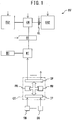
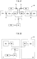
- FIG. 1 schematically shows a hybrid vehicle HV of an embodiment according to the present disclosure. Note that, in FIG. 1 , solid lines show mechanical connection, while dot lines show electrical connections.
- the hybrid vehicle HV of the embodiment according to the present disclosure is provided with an electric motor MT for generating vehicle drive force. An output shaft of this electric motor MT is connected to vehicle wheels WH.
- the hybrid vehicle HV of the embodiment according to the present disclosure is further provided with an electrical generator GN for generating electric power to be supplied to the electric motor MT.
- the generator GN is connected through a battery BT to the electric motor MT.
- the hybrid vehicle HV of the embodiment according to the present disclosure is further provided with a plurality of internal combustion engines for driving the generator GN.
- the plurality of internal combustion engines include a first internal combustion engine EG1 and a second internal combustion engine EG2.
- an output shaft of the first internal combustion engine EG1 is directly connected to an input shaft of the generator GN, while an output shaft of the second internal combustion engine EG2 is connected to the input shaft of the generator GN through an electromagnetic clutch CL.
- the generator GN When the first internal combustion engine EG1 is operated, the generator GN is driven by the first internal combustion engine EG1. Further, when the second internal combustion engine EG2 is operated with the clutch CL being turned ON, the generator GN is driven by the second internal combustion engine EG2. The electric power generated by the generator GN is sent to the battery BT. On the other hand, when the hybrid vehicle HV should be driven, electric power is sent from the battery BT to the electric motor MT and the electric motor MT is operated. That is, the hybrid vehicle HV of the embodiment according to the present disclosure is configured by a series hybrid vehicle.
- an excess electric power is stored in the battery BT.
- the internal combustion engines EG1, EG2 are intermittently operated. As opposed to this, when an amount of electric power consumed by the electric motor MT is greater than an amount of electric power sent from the generator GN to the battery BT, stored electric power is sent from the battery BT to the electric motor MT.
- the hybrid vehicle HV of the embodiment according to the present disclosure is provided with a controller CT or electronic control unit.
- This controller CT is comprised of a digital computer provided with a processor PR, memory MM, input port IP, and output port OP, which are mutually connected.
- One or more sensors SN are connected to the input port IP.
- the one or more sensors SN include, for example, sensors detecting an operating states of the internal combustion engines EG1, EG2 (rotational angles, throttle opening degrees, etc.), a sensor detecting a state of charge SOC of the battery BT (for example, remaining charged power of the battery compared with the fully charged power of the battery), a sensor detecting an amount of depression of an accelerator pedal (not shown), etc.
- the amount of depression of the accelerator pedal expresses a required vehicle load.
- the output port OP is connected to one or more control targets.
- the one or more control targets include, for example, the internal combustion engines EG1, EG2 (for example, fuel injectors, spark plugs, throttle valves, etc.), clutch CL, electric motor MT, etc.
- Various controls are performed by running programs stored in the memory MM of the controller CT at the processor PR of the controller CT.
- FIG. 2(A) shows one example of the output characteristics of the first internal combustion engine EG1
- FIG. 2(B) shows one example of the output characteristics of the second internal combustion engine EG2.
- the output characteristics of the internal combustion engines are shown by relationships of operating points of the internal combustion engines (for example, torque TQ and engine speed Ne) and a fuel consumption rate or engine operating efficiency at the corresponding operating point. The darker the color of the region, the smaller the fuel consumption rate in that region, that is, the higher the engine operating efficiency. Note that FL shows full load.
- HE1 in FIG. 2(A) shows a high efficiency region of the first internal combustion engine EG1.
- the high efficiency region HE1 of the first internal combustion engine EG1 is a region where an engine operating efficiency is relatively high in a region to which an operating point of the first internal combustion engine EG1 may belong and, for example, a region where the engine operating efficiency is higher than a predetermined first set value.
- HE2 shows a high efficiency region of the second internal combustion engine EG2.
- the high efficiency region HE2 of the second internal combustion engine EG2 is a region where an engine operating efficiency is relatively high in a region to which an operating point of the second internal combustion engine EG2 may belong to and, for example, a region where the engine operating efficiency is higher than a predetermined second set value.
- the output characteristics of the first internal combustion engine EG1 and the output characteristics of the second internal combustion engine EG2 differ from each other. Specifically, the torque TQ or output obtained when operating the first internal combustion engine EG1 in the high efficiency region HE1 thereof is lower than the torque TQ or output obtained when obtaining the second internal combustion engine EG2 in the high efficiency region HE2 thereof, while the engine operating efficiency obtained when operating the first internal combustion engine EG1 in the high efficiency region HE1 thereof is higher than the engine operating efficiency obtained when operating the second internal combustion engine EG2 in the high efficiency region HE2 thereof.
- the first internal combustion engine EG1 of the embodiment according to the present disclosure is designed for engine operating efficiency and may be referred to as an "efficiency type internal combustion engine”.
- the second internal combustion engine EG2 of the embodiment according to the present disclosure is designed for output and may be referred to as an "output type internal combustion engine”.
- FIG. 2(C) shows the output characteristics of the internal combustion engine as a whole when operating both the above-mentioned first internal combustion engine EG1 and second internal combustion engine EG2.
- HET in FIG. 2(C) shows a region to which operating points of the internal combustion engine as a whole belong when operating the first internal combustion engine EG1 in the high efficiency region HE1 thereof and operating the second internal combustion engine EG2 in the high efficiency region HE2 thereof.
- broken lines show the high efficiency region HE1 of the first internal combustion engine EG1 and the high efficiency region HE2 of the second internal combustion engine EG2.
- the operating efficiency of the internal combustion engine as a whole is increased, compared to when operating the second internal combustion engine EG2 in the high efficiency region HE2 in the high efficiency region HE2 thereof while operating the first internal combustion engine EG1 in the high efficiency region HE1 thereof.
- the operating efficiency of the internal combustion engine as a whole is further increased.
- an operating control of the internal combustion engines EG1, EG2 of the embodiment according to the present disclosure is, for example, performed as follows. That is, when a required engine output is lower than the output obtained when operating the first internal combustion engine EG1 in the high efficiency region HE1 thereof, the first internal combustion engine EG1 is operated in the high efficiency region HE1 thereof while an operation of the second internal combustion engine EG2 is stopped.
- the first internal combustion engine EG1 is operated in the high efficiency region HE1 thereof while the second internal combustion engine EG2 is operated in the high efficiency region HE2 thereof.
- the first internal combustion engine EG1 is operated in the high efficiency region HE1 thereof while the second internal combustion engine EG2 is operated in the high efficiency region HE2 thereof.
- FIG. 3 shows an example of an output characteristics of a conventional, general internal combustion engine.
- the darker the color of the region the higher the engine operating efficiency in that region.
- the internal combustion engine shown in FIG. 3 when a required engine output is relatively small, the engine is operated at the operating point XL. When the required engine output is relatively large, the engine is operated at the operating point XH. When the required engine output is a medium extent, the engine is operated at the operating point XM. Therefore, when trying to maintain the required engine output, it is difficult to maintain the engine operating efficiency high.
- the first internal combustion engine EG1 when the required engine output is relatively small, the first internal combustion engine EG1 is selected as an internal combustion engine to be operated. In this case, even if the second internal combustion engine EG2 is selected or both of the first internal combustion engine EG1 and the second internal combustion engine EG2 are selected, it is possible to secure the required engine output. However, by selecting the first internal combustion engine EG1 and operating it in the high efficiency region HE1 thereof, it is possible to maximize the operating efficiency of the internal combustion engine as a whole. On the other hand, when the required engine output is large, both of the first internal combustion engine EG1 and the second internal combustion engine EG2 are selected and they are operated in the respective high efficiency regions HE1, HE2 thereof. As a result, it is possible to maintain the engine operating efficiency high while securing the required engine output.
- the controller CT is configured to select one or more internal combustion engines from the plurality of internal combustion engines so that, when operating the selected one or more internal combustion engines in respective high efficiency regions thereof, an engine output satisfies a required engine output and an engine operating efficiency is maximum, and to operate the selected one or more internal combustion engines in the respective high efficiency regions thereof.
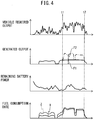
- FIG. 4 is a time chart showing a fuel consumption rate etc. of the hybrid vehicle HV of the embodiment according to the present disclosure.
- a mean value over time of a vehicle required output is relatively small, and the first internal combustion engine EG1 is operated while an operation of the second internal combustion engine EG2 is stopped.
- both of the first internal combustion engine EG1 and the second internal combustion engine EG2 are operated.
- the time t2 when the mean value over time of the vehicle required output becomes relatively small, an operation of the second internal combustion engine EG2 is stopped while the first internal combustion engine EG1 is kept operating. Note that, in FIG.
- F1 shows an amount of contribution of the first internal combustion engine EG1
- F2 shows an amount of contribution of the second internal combustion engine EG2.
- a solid line X shows a fuel consumption rate or engine operating efficiency of the hybrid vehicle HV of the embodiment according to the present disclosure
- a broken line Z shows a fuel consumption rate or engine operating efficiency of a hybrid vehicle provided with the conventional internal combustion engine having the output characteristics shown in FIG. 3 .
- FIG. 4 in the embodiment according to the present disclosure, it is possible to improve the fuel consumption rate or engine operating efficiency regardless of the output.
- the SOC of the battery BT is larger than a predetermined set value when the electric motor MT should be driven, the electric power stored in the battery BT is sent to the electric motor MT while operations of the internal combustion engines EG1, EG2 are stopped. In other words, if the SOC of the battery BT is smaller than the set value when the electric motor MT should be driven, one or more internal combustion engines EG1, EG2 are operated.
- FIG. 5 shows a routine for performing control of engine operation of the above-mentioned embodiment according to the present disclosure.
- step 100 it is judged if the SOC of the battery BT is smaller than a predetermined set value SOCX. If SOC ⁇ SOCX, the routine then proceeds to step 101 where operations of both of the first internal combustion engine EG1 and the second internal combustion engine EG2 are stopped. As opposed to this, if SOC ⁇ SOCX, the routine then proceeds to step 102 where it is judged if the required engine output ROP is smaller than an output ROP1 obtained when the first internal combustion engine EG1 is operated in the high efficiency region HE1 thereof.
- step 103 the second internal combustion engine EG2 is operated in the high efficiency region HE2 thereof while an operation of the first internal combustion engine EG1 is stopped.
- step 104 the routine proceeds to step 104 where the first internal combustion engine EG1 is operated in the high efficiency region HE1 thereof and the second internal combustion engine EG2 is operated in the high efficiency region HE2 thereof.
- the required engine output is secured by totaling up the outputs of the one or plurality of internal combustion engines.
- the internal combustion engines are compact.
- by sending an exhaust heat of the already operating internal combustion engine/engines to the other internal combustion engine/engines it is further possible to shorten the warm-up times of the other internal combustion engine/engines.
- the plurality of internal combustion engines are respectively operated in the high efficiency regions thereof.
- measures against vibration and measures against noise suitable for the respective operating regions or internal combustion engines can be individually devised.
- the plurality of internal combustion engines include an internal combustion engine configured to perform a mirror cycle and an internal combustion engine configured to perform an Otto cycle.
- the former is an example of the first internal combustion engine EG1 or efficiency type internal combustion engine, while the latter is one example of the second internal combustion engine EG2 or output type internal combustion engine.
- the plurality of internal combustion engines include an internal combustion engine configured to perform HCCI (homogeneous charge compression ignition) combustion and an internal combustion engine configured to perform SI (spark ignition) combustion.
- HCCI homogeneous charge compression ignition
- SI spark ignition
- the plurality of internal combustion engines include an internal combustion engine configured to perform PCCI (premixed charge compression ignition) combustion and an internal combustion engine configured to perform CI (compression ignition) combustion.
- the former is an example of the first internal combustion engine EG1 or efficiency type internal combustion engine, while the latter is one example of the second internal combustion engine EG2 or output type internal combustion engine.
- the plurality of internal combustion engines include a long stroke internal combustion engine with a stroke length larger than a bore size thereof, and a short stroke internal combustion engine with a bore size larger than a stroke length thereof.
- the former is one example of the first internal combustion engine EG1 or efficiency type internal combustion engine, while the latter is one example of the second internal combustion engine EG2 or output type internal combustion engine.
- the plurality of internal combustion engines include an internal combustion engine with a relatively high mechanical compression ratio and an internal combustion engine with a relatively low mechanical compression ratio.
- the former is one example of the first internal combustion engine EG1 or efficiency type internal combustion engine, while the latter is one example of the second internal combustion engine EG2 or output type internal combustion engine.
- an internal combustion engine able to change output characteristics.
- This internal combustion engine includes, for example, an internal combustion engine switching the combustion cycle between a mirror cycle and an Otto cycle and an internal combustion engine switching combustion between HCCI combustion and SI combustion.
- the internal combustion engine cannot change the output characteristics.
- a configuration enabling change of the output characteristics for example, a variable valve operation mechanism etc., is not necessary. Therefore, the configuration of the internal combustion engine can be simplified more. Further, it is possible to eliminate a torque fluctuation or deterioration in exhaust emission which may occur when switching output characteristics.
- the plurality of internal combustion engines include a single-cylinder internal combustion engine. In another example, all of the plurality of internal combustion engines are single-cylinder internal combustion engines. This makes a hybrid vehicle HV more compact. Furthermore, in another embodiment, the plurality of internal combustion engines include a multiple cylinder internal combustion engine.
- the plurality of internal combustion engines include a crank internal combustion engine which converts reciprocating motion of a piston to rotary motion by a crank mechanism and outputs the same.
- all of the plurality of internal combustion engines are crank internal combustion engines.
- the plurality of internal combustion engines include a rotary cylinder internal combustion engine. Furthermore, in another example, all of the plurality of internal combustion engines are rotary cylinder internal combustion engines.
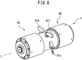
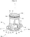
- FIG. 6 to FIG. 12 show a rotary cylinder internal combustion engine 1 of the embodiment according to the present disclosure.
- This rotary cylinder internal combustion engine 1 overall has a cylindrical shape or columnar shape having a longitudinal center axis (for example, see FIGS. 6 , 8 , and 9 ).
- This longitudinal center axis matches with a rotational axis L which will be explained later.
- the rotary cylinder internal combustion engine 1 of the embodiment according to the present disclosure is formed substantially symmetrically with respect to a symmetry plane P vertical to the rotational axis L (for example, see FIGS. 8 and 9 ).
- the rotary cylinder internal combustion engine 1 of the embodiment according to the present disclosure is a four-stroke engine. In another embodiment according to the present disclosure (not shown), the rotary cylinder internal combustion engine 1 is a two-stroke engine. On the other hand, in the internal combustion engine 1 of the embodiment according to the present disclosure, SI (spark ignition) combustion is performed. In an internal combustion engine of another embodiment according to the present disclosure (not shown), CI (compression ignition) combustion, HCCI (homogeneous charge compression ignition) combustion or PCCI (premixed charge compression ignition) combustion is performed. As fuel, a liquid fuel such as gasoline, diesel fuel, or alcohol, or a gaseous fuel such as liquefied petroleum gas (LPG), compressed natural gas (CNG), or hydrogen, is used.
- LPG liquefied petroleum gas
- CNG compressed natural gas
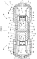
- the rotary cylinder internal combustion engine 1 of the embodiment according to the present disclosure is provided with a single cylinder 10 able to rotate about the rotational axis L (for example, see FIGS. 7 to 9 ).
- the cylinder 10 overall has a hollow, cylindrical shape. Longitudinal center axes of an inner circumferential surface 11 having a cylindrical shape and an outer circumferential surface 12 having a cylindrical shape of the cylinder 10 respectively match the rotational axis L.
- the cylinder 10 can rotate in an R direction (for example, see FIGS. 8 and 9 ).
- the rotary cylinder internal combustion engine 1 of the embodiment according to the present disclosure is further provided with an outer circumferential member 20 (for example, see FIGS. 7 to 9 ).
- This outer circumferential member 20 overall has a hollow, cylindrical shape.
- a longitudinal center axis of an inner circumferential surface 21 having a cylindrical shape of the outer circumferential member 20 matches with the rotational axis L.
- the above-mentioned cylinder 10 is housed in this outer circumferential member 20 to be able to rotate about the rotational axis L, therefore the outer circumferential member 20 is positioned around the cylinder 10.
- the outer circumferential member 20 of the embodiment according to the present disclosure is stationarily set. That is, the outer circumferential member 20 is set or mounted to be unable to rotate about the rotational axis L and to be unable to move in the rotational axis L direction.
- the outer circumferential member 20 of the embodiment according to the present disclosure is comprised of a plurality of members. Specifically, the outer circumferential member 20 is provided with a center part 22, two end parts 23, 23, and two housings 24, 24 (for example, see FIGS. 7 to 9 ).
- the center part 22 has a hollow, cylindrical shape with open opposite ends in the rotational axis L direction, and is arranged on the symmetry plane P.
- the end parts 23, 23 respectively have hollow, cylindrical shapes with closed outside ends in the rotational axis L direction and open inside ends in the rotational axis L direction, and are arranged with spaces 25 from the center part 22 in the rotational axis L direction (for example, see FIGS. 7 and 9 ).
- the spaces 25 have annular shapes in the circumferential direction about the rotational axis L.
- the housings 24, 24 have hollow, cylindrical shapes with open opposite ends in the rotational axis L direction, and are fixed to the center part 22 and the corresponding end parts 23, 23 by for example bolts 26, 26 (for example, see FIGS. 8 and 9 ).
- the center part 22 and the end parts 23, 23 are connected to each other by the housings 24, 24 and the spaces 25, 25 are separated from the outside by the housings 24, 24.
- the inner circumferential surface 21 of the outer circumferential member 20 is comprised of an inner circumferential surface of the center part 22 and inner circumferential surfaces of the end parts 23, 23.
- the outer circumferential member 20 is comprised of an integral member.
- the cylinder 10 is housed in the outer circumferential member 20 so that the outer circumferential surface 12 of the cylinder 10 slides with respect to the inner circumferential surface of the center part 22 (for example, see FIGS. 8 and 9 ). Further, projecting parts 13, 13, which are provided respectively at two ends in the rotational axis L direction of the cylinder 10, are held to be able to rotate about the rotational axis L, in corresponding through holes 27, 27, which are provided at two ends in the rotational axis L direction of the outer circumferential member 20 (for example, see FIG. 7 to 9 ). In this way, the cylinder 10 is held by the outer circumferential member 20 to be able to rotate about the rotational axis L.
- the outer circumferential surface 12 of the cylinder 10 and the inner circumferential surfaces of the end parts 23, 23 are separated from each other. Further, in the embodiment according to the present disclosure, an output shaft (not shown) is connected to one projecting part 13.
- the rotary cylinder internal combustion engine 1 of the embodiment according to the present disclosure is further provided with a single combustion chamber 30 defined inside the cylinder 10 (for example, see FIGS. 8 and 9 ).
- This combustion chamber 30 is positioned on the symmetry plane P.
- the rotary cylinder internal combustion engine 1 of the embodiment according to the present disclosure is further provided with two drive parts 40, 40 arranged along the rotational axis L (for example, see FIGS. 6 to 9 ).
- the drive parts 40, 40 of the embodiment according to the present disclosure are respectively provided with single pistons 50 (for example, see FIGS. 7 to 9 ).
- the pistons 50 are housed in the cylinder 10 to be able to slide in the rotational axis L direction.
- the piston 50 of one drive part 40 and the piston 50 of the other drive part 40 face each other inside the cylinder 10.
- the above-mentioned combustion chamber 30 is defined between these pistons 50, 50 in the cylinder 10. Note that, longitudinal center axes of the pistons 50 match the rotational axis L.
- recessed parts 52 are formed in top surfaces 51 of the pistons 50 (for example, see FIG. 11 ).
- the recessed parts 52 extend in diametrical directions of the pistons 50 and reach circumferential surfaces of the pistons 50.
- two notches 52a, 52b are formed separated by 180 degrees in the circumferential direction about the rotational axis L.
- the recessed part 52 of one piston 50 and the recessed part 52 of the other piston 50 are aligned to each other in the circumferential direction about the rotational axis L. Therefore, the notches 52a, 52b of one piston 50 and the notches 52a, 52b of the other piston 50 are also aligned to each other in the circumferential direction about the rotational axis L.
- the drive parts 40, 40 of the embodiment according to the present disclosure are respectively further provided with pluralities of slots 60 which are formed in a circumferential surface of the cylinder 10 separated at equal intervals in the circumferential direction about the rotational axis L (for example, see FIGS. 7 to 9 ).
- the slots 60 comprise two slots 60a, 60b separated from each other by 180 degrees in the circumferential direction about the rotational axis L.
- the slots 60a, 60b are respectively formed in the circumferential surface of the cylinder 10 at the opposite sides to the combustion chamber 30 relative to the pistons 50 (for example, see FIGS. 7 to 9 ).
- the combustion chamber 30 is positioned at the inner side in the rotational axis L direction with respect to the pistons 50, while the slots 60a, 60b are positioned at the outer sides in the rotational axis L direction with respect to the pistons 50. Note that the slots 60a, 60b are aligned in the rotational axis L direction.
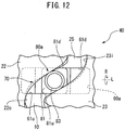
- the slots 60a, 60b of the embodiment according to the present disclosure respectively have rectangular shapes elongated in the rotational axis L direction and are provided with two engaging surfaces 61u, 61d separated from each other in the circumferential direction about the rotational axis L and extending in the rotational axis L direction (for example, see FIGS. 9 and 12 ).
- the engaging surfaces 61u are positioned at upstream sides in the rotational direction R about the rotational axis L while the engaging surfaces 61d are positioned at downstream sides.
- the drive parts 40, 40 of the embodiment according to the present disclosure are respectively provided with single cams 70 (for example, see FIGS. 8 and 9 ).
- the cams 70 are stationarily set around the slots 60.
- the cams 70 have profiles oscillating in the rotational axis L direction while being annular in the circumferential direction about the rotational axis L.
- the profiles of the cams 70, 70 are respectively formed so that the pistons 50, 50 of the two drive parts 40, 40 are synchronized to each other.
- the cams 70 are comprised of groove cams. Specifically, the cams 70 are provided with outside end faces 22o of the center parts 22 in the rotational axis L direction, inside end faces 23i of the end parts 23 in the rotational axis L direction, and the spaces 25 of the outer circumferential members 20 defined by these end faces 22o, 23i (for example, see FIGS. 8 , 9 , and 12 ). These end faces 22o, 23i function as cam faces of the cams 70. In this case, the cams 70 may be held by the outer circumferential members 20. Further, the cam 70 of one drive part 40 and the cam 70 of the other drive part 40 may be held by the common outer circumferential member 20.
- the drive parts 40, 40 of the embodiment according to the present disclosure are respectively provided with pluralities of followers 80 which are provided integrally with the pistons 50 and separated at equal intervals in the circumferential direction about the rotational axis L (for example, see FIGS. 7 to 9 ).
- the followers 80 of the embodiment according to the present disclosure comprise two followers 80a, 80b separated from each other by 180 degrees in the circumferential direction about the rotational axis L. Note that the followers 80a, 80b are aligned to each other in the rotational axis L direction.
- the followers 80a, 80b respectively extend from the pistons 50 through the slots 60a, 60b to the cams 70, and are configured to move along the profiles of the cams 70 (for example, see FIGS. 8 and 9 ).
- the followers 80a, 80b of the embodiment according to the present disclosure respectively are provided with sliders 81, arms 82, and rollers 83 (for example, see FIGS. 8 , 9 , and 11 ).
- the sliders 81 are fit into through holes 53 formed in circumferential walls of the pistons 50. Further, the sliders 81 have two engaging surfaces 81u, 81d extending in the rotational axis L direction.
- the arms 82 extend through the sliders 81 outward in a radial direction.
- the arms 82 of the followers 80a and the arms 82 of the other followers 80b are integrally formed. At tips of the arms 82, rollers 83 are attached to be able to rotate about a longitudinal center axis L1 of the arms 82.
- the followers 80a, 80b are fastened by fastening sleeves 84 to the pistons 50.
- the rollers 83 engage with the cams 70. That is, circumferential surfaces of the rollers 83 abut against the cam faces 22o, 23i of the cams 70. As a result, the followers 80a, 80b can move together with the pistons 50 along the profiles of the cams 70.
- the sliders 81, 81 are housed in the slots 60a, 60b.
- the engaging surfaces 81u of the sliders 81 engage with the engaging surfaces 61u of the slots 60a, 60b and the engaging surfaces 81d of the sliders 81 engage with the engaging surfaces 61d of the slots 60a, 60b.
- the sliders 81 are restricted from relative movement with respect to the cylinder 10 in the circumferential direction about the rotational axis L by the slots 60a, 60b.
- the slots 60 of the embodiment according to the present disclosure are configured to restrict relative movement of the followers 80 together with the pistons 50 with respect to the cylinder 10 in the circumferential direction about the rotational axis L, while allowing relative movement of the followers 80 together with the pistons 50 with respect to the cylinder 10 in the rotational axis L direction.
- the rotary cylinder internal combustion engine 1 of the embodiment according to the present disclosure is further provided with a plurality of communication holes 90 formed in the circumferential surface of the cylinder 10 to be separated at equal intervals in the circumferential direction about the rotational axis L and to communicate with the combustion chamber 30.
- the communication holes 90 comprise two communication holes 90a, 90b separated by 180 degrees in the circumferential direction about the rotational axis L (for example, see FIGS. 8 and 10 ). These communication holes 90a, 90b are aligned to each other in the rotational axis L direction, and are arranged on, for example, the symmetry plane P (for example, see FIGS. 8 and 9 ).
- the rotary cylinder internal combustion engine 1 of the embodiment according to the present disclosure is further provided with a single intake hole 90i formed at the center part 22 of the outer circumferential member 20 (for example, see FIG. 10 ).
- the intake hole 90i is aligned with the communication holes 90a, 90b in the rotational axis L direction.
- the intake hole 90i in the embodiment according to the present disclosure is formed in the outer circumferential member 20 so that the intake hole 90i communicates with the communication holes 90a, 90b when the rotational angle ⁇ about the rotational axis L of the cylinder 10 is in a predetermined intake angle range IN.
- the outer circumferential surface 12 of the cylinder 10 slides against the inner circumferential surface 21 of the center part 22 of the outer circumferential member 20.
- the communication holes 90a, 90b face the inner circumferential surface 21 of the outer circumferential member 20
- the communication holes 90a, 90b are closed by this inner circumferential surface 21, therefore the combustion chamber 30 is sealed.
- the combustion chamber 30 communicates with the intake hole 90i through the communication holes 90a, 90b.
- An intake pipe 91i is connected with this intake hole 90i (for example, see FIGS. 6 and 10 ).
- a fuel injector (not shown) for injecting fuel inside the intake pipe 91i
- a throttle valve (not shown) for controlling the amount of intake flowing through the inside of the intake pipe 91i, etc. are arranged in the intake pipe 91i.
- the rotary cylinder internal combustion engine 1 of the embodiment according to the present disclosure is further provided with a single exhaust hole 90e formed at the center part 22 of the outer circumferential member 20 (for example, see FIG. 10 ).
- the exhaust hole 90e is aligned with the communication holes 90a, 90b in the rotational axis L direction, and therefore is also aligned with the intake hole 90i.
- the exhaust hole 90e of the embodiment according to the present disclosure is formed or positioned in the outer circumferential member 20 so that the exhaust hole 90e communicates with the communication holes 90a, 90b when the rotational angle ⁇ of the cylinder 10 is within a predetermined exhaust angle range EX.
- the communication holes 90a, 90b communicate with the exhaust hole 90e, and therefore the combustion chamber 30 communicates with the exhaust hole 90e through the communication holes 90a, 90b.
- An exhaust pipe 91e is connected with this exhaust hole 90e (for example, see FIGS. 6 and 10 ).
- a catalyst for purifying exhaust gas (not shown), etc. are arranged in the exhaust pipe 91e.
- the rotary cylinder internal combustion engine 1 of the embodiment according to the present disclosure is further provided with a single spark plug housing hole 90s formed at the outer circumferential member 20 (for example, see FIG. 10 ).
- the spark plug housing hole 90s is aligned with the communication holes 90a, 90b in the rotational axis L direction, and therefore is also aligned with the intake hole 90i and exhaust hole 90e.
- a spark plug 91s is sealingly housed in spark plug housing hole 90s.
- the spark plug housing hole 90s of the embodiment according to the present disclosure is formed or positioned in the outer circumferential member 20 so that the spark plug 91s faces the communication holes 90a, 90b when the rotational angle ⁇ of the cylinder 10 is in a predetermined ignition angle range SP.
- FIG. 13 shows behavior of the pistons 50 of the embodiment according to the present disclosure.
- the abscissa indicates the rotational angle ⁇ of the cylinder 10 when referenced to a certain top dead center TDCe, while the ordinate indicates an amount of displacement in the rotational axis L direction of the top surfaces 51 of the pistons 50 when referenced to the symmetry plane P.
- the pistons 50 move together with the followers 80 along the profiles of the cams 70. Therefore, the behavior of the pistons 50 shown in FIG. 13 shows the profiles of the cams 70.
- the pistons 50 reciprocate in the rotational axis L direction as the cylinder 10 rotates about the rotational axis L.
- the rotary cylinder internal combustion engine 1 of the embodiment according to the present disclosure is a four-stroke engine.
- an intake stroke, compression stroke, expansion stroke, and exhaust stroke which form one combustion cycle, are successively and repeatedly performed.
- the intake stroke corresponds to a rotational angle range from a top dead center TDCe to a bottom dead center BDCc.
- the compression stroke corresponds to a rotational angle range from the bottom dead center BDCc to a top dead center TDCc.
- the expansion stroke corresponds to a rotational angle range from the top dead center TDCc to a bottom dead center BDCe.
- the exhaust stroke corresponds to a rotational angle range from the bottom dead center BDCe to the top dead center TDCe. Therefore, in the embodiment according to the present disclosure, the top dead center TDCe is an exhaust top dead center, the bottom dead center BDCc is a compression bottom dead center, the top dead center TDCc is a compression top dead center, and the bottom dead center BDCe is an exhaust bottom dead center.
- the profiles of the cams 70 are formed so that every time the cylinder 10 rotates once about the rotational axis L, two combustion cycles are performed. Therefore, the profiles of the cams 70 corresponding to the rotational angle ⁇ of the cylinder 10 of 0 to 180 degrees and the profile of the cam 70 corresponding to the rotational angle ⁇ of the cylinder 10 of 180 to 360 degrees are identical to each other.
- positions of the pistons 50 or followers 80a, 80b in the rotational axis L direction at a certain rotational angle ⁇ (0 ⁇ 180 degrees) and positions of the pistons 50 or followers 80a, 80b in the rotational axis L direction at a rotational angle ⁇ +180 degrees are identical to each other.
- the profiles of the cams 70 are formed to have 180 degree symmetry about the rotational axis L.
- the profiles of the cams 70 of the embodiment according to the present disclosure does not have 90 degree symmetry about the rotational axis L.
- the above-mentioned intake angle range IN is set to a range from the exhaust top dead center TDCe to the compression bottom dead center BDCc, that is, the intake stroke (for example, see FIG. 13 ).
- the intake angle range IN starts from a rotational angle ⁇ of the cylinder 10 different from the exhaust top dead center TDCe.
- the intake angle range IN ends at a rotational angle ⁇ of the cylinder 10 different from the compression bottom dead center BDCc.
- the exhaust angle range EX is set to a range from the exhaust bottom dead center BDCe to the exhaust top dead center TDCe, that is, the exhaust stroke (for example, see FIG. 13 ).
- the exhaust angle range EX starts from a rotational angle ⁇ of the cylinder 10 different from the exhaust bottom dead center BDCe.
- the exhaust angle range EX ends at a rotational angle ⁇ of the cylinder 10 different from the exhaust top dead center TDCe.
- the ignition angle range SP is set to a range around the compression top dead center TDCc (for example, see FIG. 13 ). In another embodiment (not shown), the ignition angle range SP is set to a rotational angle ⁇ of the cylinder 10 different from one around the compression top dead center TDCc.
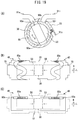
- FIGS. 14(A), 14(B), and 14(C) schematically show the rotary cylinder internal combustion engine 1 of the embodiment according to the present disclosure in the intake stroke.
- the pistons 50, 50 move so as to separate from each other.
- the volume of the combustion chamber 30 increases.
- the communication holes 90a communicate with the intake hole 90i.
- intake gas for example, an air-fuel mixture
- FIGS. 15(A), 15(B), and 15(C) schematically show the rotary cylinder internal combustion engine 1 of the embodiment according to the present disclosure in the compression stroke.
- the pistons 50, 50 move so as to approach each other.
- the communication holes 90a, 90b are closed and, therefore intake gas in the combustion chamber 30 is compressed.
- FIGS. 16(A), 16(B), and 16(C) schematically show the rotary cylinder internal combustion engine 1 of the embodiment according to the present disclosure when the rotational angle ⁇ of the cylinder 10 is within the ignition angle range SP or around the compression top dead center TDCc.
- the combustion chamber 30 is mainly defined in the recessed parts 52, 52 of the facing pistons 50, 50.
- the pistons 50, 50 are respectively formed so that when the rotational angle ⁇ of the cylinder 10 is within the ignition angle range SP, the notches 52a, 52b of the pistons 50 face the communication holes 90a, 90b.
- the spark plug 91s faces the combustion chamber 30 through the communication holes 90a and notches 52a or communication holes 90b and notches 52b (see FIGS. 16 and 17 ). At this time, an ignition action by the spark plug 91s is performed. As a result, the air-fuel mixture inside the combustion chamber 30 is ignited and burned.
- FIGS. 18(A), 18(B), and 18(C) schematically show the rotary cylinder internal combustion engine 1 of the embodiment according to the present disclosure in the expansion stroke.
- the communication holes 90a, 90b are closed. Therefore, due to combustion, the pistons 50, 50 move to be separated from each other.
- FIGS. 19(A), 19(B), and 19(C) schematically show the rotary cylinder internal combustion engine 1 of the embodiment according to the present disclosure in the exhaust stroke.
- the pistons 50, 50 move so as to approach each other.
- the communication hole 90b communicates with the exhaust hole 90e.
- exhaust gas flows from the combustion chamber 30 into the exhaust pipe 91e.
- the intake hole 90i communicates with the communication hole 90b.
- the spark plug 91s faces the combustion chamber 30 through the communication hole 90b.
- the exhaust hole 90e communicates with the communication hole 90a.
- the combustion cycle number of the embodiment according to the present disclosure is set to 2 (for example, see FIG. 13 ). In another embodiment (not shown), the combustion cycle number is set to one or three or more. Further, in the embodiment according to the present disclosure, a single intake hole 90i, a single exhaust hole 90e, and a single spark plug housing hole 90s are provided and the communication holes of the same number as the combustion cycle number are provided separated at equal intervals in the circumferential direction about the rotational axis L.
- the number of the intake holes is the same as the number of combustion cycles
- the number of exhaust holes is the same as the number of combustion cycles
- number of the spark plug housing holes is the same as the number of combustion cycles and are provided separated at equal intervals in the circumferential direction about the rotational axis L and a single communication hole is provided.
- FIG. 20 to FIG. 22 show the drive part 40 at the right side in FIG. 8 and FIG. 9 , for example.
- outward in the rotational axis L direction means a direction from a top dead center toward a bottom dead center
- inward in the rotational axis L direction means a direction from a bottom dead center toward a top dead center.
- combustion performed in the combustion chamber 30 causes a force F11 outward in the rotational axis L direction to act on the piston 50 and the followers 80a, 80b integral with the same.
- a reaction force F12 in a direction vertical to the cam face 23i acts on the followers 80a, 80b through engagement between the rollers 83, 83 of the followers 80a, 80b and the cam face 23i of the cam 70.
- a force F13 in the circumferential direction about the rotational axis L acts on the cylinder 10 through engagement between the engaging surfaces 81d, 81d of the sliders 81, 81 of the followers 80a, 80b and the engaging surfaces 61d, 61d of the slots 60a, 60b of the cylinder 10. Therefore, the cylinder 10 is rotated in the circumferential direction R about the rotational axis L. That is, when combustion is performed in the combustion chamber 30, the piston 50 moves together with the followers 80a, 80b along the profile of the cam 70, to thereby rotate the cylinder 10 about the rotational axis L. In this way, movement of the piston 50 in the rotational axis L direction is converted to rotary motion about the rotational axis L. This rotary motion is taken out as engine output from the output shaft (not shown) coupled with the projecting part 13 of the cylinder 10 (for example, see FIGS. 12 to 14 ).
- rotation of the cylinder 10 in the circumferential direction R about the rotational axis L causes a force F21 in the circumferential direction about the rotational axis L to act on the followers 80a, 80b through engagement between the engaging surfaces 61u, 61u of the slots 60a, 60b of the cylinder 10 and the engaging surfaces 81u of the sliders 81, 81 of the followers 80a, 80b.
- a reaction force F22 in a direction vertical to the cam face 23i acts on the followers 80a, 80b through engagement between the rollers 83, 83 of the followers 80a, 80b and the cam face 23i of the cam 70.
- a force F23 inward in the rotational axis L direction acts on the followers 80a, 80b and piston 50. Therefore, the piston 50 moves inward in the rotational axis L direction.
- reciprocating motion of the piston 50 is converted to rotary motion without using a crank mechanism. Therefore, the rotary cylinder internal combustion engine 1 can be made more compact. Further, unlike a conventional internal combustion engine using a crank mechanism, no thrust force is generated at the piston. Furthermore, the cylinder 10 itself is rotated, so the number of parts is reduced.
- two drive parts 40, 40 and, therefore two pistons 50, 50 are provided.
- the profiles of the cams 70, 70 are formed so that phases of these pistons 50, 50 are synchronized to each other.
- the pistons 50, 50 move to be separated from each other, while in the compression stroke and exhaust stroke, the pistons 50, 50 move so as to approach each other. Therefore, vibration due to the reciprocating motions of the pistons 50, 50 is cancelled out.
- the profiles of the cams 70, 70 are formed so that a stroke length STc from the compression bottom dead center BDCc to the compression top dead center TDCc is shorter than a stroke length STe from the compression top dead center TDCc to the exhaust bottom dead center BDCe.
- the profiles of the cams 70, 70 are formed so that the stroke length STc from the compression bottom dead center BDCc to the compression top dead center TDCc and the stroke length STe from the compression top dead center TDCc to the exhaust bottom dead center BDCe are equal to each other.
- an Otto cycle which has an expansion ratio and a compression ratio equal to each other is realized.
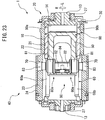
- FIG. 23 shows a rotary cylinder internal combustion engine 1 of another embodiment according to the present disclosure.
- the rotary cylinder internal combustion engine 1 of the other embodiment differs in configuration from the rotary cylinder internal combustion engine 1 of the above-mentioned embodiment in that it is provided with a single drive part 40.
- the combustion chamber 30 is defined between the top surface of the piston 50 and the end face 14 in the rotational axis L direction of the cylinder 10.
- the rest of the configuration of the rotary cylinder internal combustion engine 1 of the other embodiment according to the present disclosure is similar to the configuration of the rotary cylinder internal combustion engine 1 of the above-mentioned embodiment according to the present disclosure, and therefore explanations therefor will be omitted.
- FIGS. 24(A) and 24(B) show another embodiment of the follower 80a.
- the arm 82 of the follower 80a is provided with two branched parts 82a, 82a.
- the branched parts 82a, 82a respectively rotatably hold rollers 83a, 83a.
- One roller 83a engages with one cam face 22o of the cam 70, while the other roller 83a engages with the other cam face 23i.
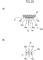
- FIGS. 25(A) and 25(B) show another embodiment of the cam 70 and follower 80a.
- the arm 82 of the follower 80a is provided with two branched parts 82a, 82a.
- the branched parts 82a, 82a respectively rotatably hold rollers 83a, 83a.
- the cam 70 has a shape of a projection projecting out from the inner circumferential surface 21 of the outer circumferential member 20. Two side surfaces of this projection form cam faces.
- One roller 83a engages with one cam face of the cam 70, while the other roller 83a engages with the other cam face.
- fuel is injected from a fuel injector attached to the intake pipe 91i into the intake pipe 91i.
- fuel is directly injected from the fuel injector attached to the outer circumferential member 20 into the combustion chamber 30.
- the fuel injector is housed in a fuel injector housing hole formed in the outer circumferential member 20, and is arranged on the inner circumferential surface 21 of the outer circumferential member 20 so as to face the communication holes 90a, 90b when the rotational angle of the cylinder 10 is within a predetermined injection angle range.
- the profile of the cam 70 is formed to have 180 degree symmetry, without having 90 degree symmetry, in the circumferential direction about the rotational axis L.
- the profile of the cam 70 is formed to have a predetermined angle symmetry in the circumferential direction about the rotational axis L. In one example, one example of the predetermined angle is 90 degrees.
- the profile of the cam 70 is formed asymmetric in the circumferential direction about the rotational axis L.
- the drive part 40 is provided with two slots 60a, 60b.
- the drive part 40 is provided with one or three or more slots 60.
- the drive part 40 is provided with two followers 80a, 80b.
- the drive part 40 is provided with one or three or more followers 80.
- the number of followers 80 is the same as or smaller than the number of slots 60.
- the profile of the cam 70 has 180 degree symmetry about the rotational axis L, rather than 90 degree symmetry, one or two followers 80 are provided. If the profile of the cam 70 has 90 degree symmetry about the rotational axis L, one, two, or four followers 80 are provided. Therefore, expressed comprehensively, the profile of the cam 70 is formed to have a predetermined angle symmetry in the circumferential direction about the rotational axis L, and the follower 80 is comprised of a plurality of followers separated from each other at equal intervals in the circumferential direction about the rotational axis L, and the number of followers is determined according to the predetermined angle. Increasing of the number of followers 80 reduces or limits loads acting on the followers 80.
- the slider 81 of the follower 80 is omitted.
- the arm 82 engages with the engaging surfaces 61u, 61d of the slot 60a.
- the roller 83 of the follower 80 is omitted. In this case, for example, the arm 82 engages with the cam surface of the cam 70.
- FIG. 27 shows an example of an arrangement of a plurality of internal combustion engines.
- the plurality of internal combustion engines are comprised of the first internal combustion engine EG1 and the second internal combustion engine EG2.
- the first internal combustion engine EG1 and the second internal combustion engine EG2 are respectively comprised of single-cylinder rotary cylinder internal combustion engines.
- the first internal combustion engine EG1 is arranged at one side of the generator GN, while the second internal combustion engine EG2 is arranged at the other side of the generator GN.
- the first internal combustion engine EG1 is arranged so that the rotational axis L1 of the first internal combustion engine EG1 matches the axis LG of the input shaft of the generator GN
- the second internal combustion engine EG2 is arranged so that the rotational axis L2 of the second internal combustion engine EG2 matches the axis LG of the input shaft of the generator GN. Therefore, the first internal combustion engine EG1 and the second internal combustion engine EG2 are arranged so that the rotational axis L1 of the first internal combustion engine EG1 and the rotational axis L2 of the second internal combustion engine EG2 match each other. This makes the hybrid vehicle HV more compact.
- FIG. 28 to FIG. 32 show other examples of the hybrid vehicle HV.
- the example shown in FIG. 28 differs from the example of FIG. 1 on the point that the first internal combustion engine EG1 is coupled with the generator GN through an electromagnetic clutch CL.
- an operation of the second internal combustion engine EG2 is stopped while the first internal combustion engine EG1 is operated.
- both the first internal combustion engine EG1 and the second internal combustion engine EG2 are operated.
- the required engine output is the medium extent, an operation of the first internal combustion engine EG1 is stopped while the second internal combustion engine EG2 is operated. That is, patterns of internal combustion engines to be operated increase, and thus it is possible to control engine operation in more detail.
- the example shown in FIG. 29 differs from the example of FIG. 1 on the point that the first internal combustion engine EG1 and the second internal combustion engine EG2 are respectively connected to the first generator GN1 and the second generator GN2. This increases a degree of freedom in mounting the first internal combustion engine EG1 and the second internal combustion engine EG2 as well as the first generator GN1 and the second generator GN2.
- the example shown in FIG. 30 differs from the example of FIG. 29 on the point that the first internal combustion engine EG1 is provided with a plurality of internal combustion engines EG1a, EG1b coupled to each other by an electromagnetic clutch CL and that the second internal combustion engine EG2 is provided with a plurality of internal combustion engines EG2a, EG2b coupled to each other by an electromagnetic clutch CL.
- the patterns of internal combustion engines to be operated increase, and thus it is possible to control engine operation in more detail.
- the example shown in FIG. 31 differs from the example of FIG. 30 on the point that the output shaft of the first internal combustion engine EG1 is coupled with an input shaft of a first motor-generator MG1, the output shaft of the second internal combustion engine EG2 is coupled with an input shaft of a second motor-generator MG2, and an output shaft of the first motor-generator MG1 and an output shaft of the second motor-generator MG2 are respectively coupled with a vehicle wheels WH through electromagnetic clutches CL.
- the first motor-generator MG1 and the second motor-generator MG2 operate as electric motors, electric power is received from the battery BT.
- electric power is received from the battery BT.
- the output of the first internal combustion engine EG1 is transmitted to one or both of the first generator GN1 and the vehicle wheels WH, while the output of the second internal combustion engine EG2 is transmitted to one or both of the second generator GN2 and the vehicle wheels WH. That is, in these examples, the vehicle wheels WH are driven by not only the electric motor MT, but also the motor-generators MG1, MG2 or generators GN1, GN2. In other words, the hybrid vehicle HV is not limited to a series hybrid vehicle.
- the example shown in FIG. 32 differs from the example of FIG. 29 on the point that the hybrid vehicle HV includes a first vehicle V1 and a second vehicle V2. which can be connected to each other by, for example, towing, and that part of components of the hybrid vehicle HV (for example, the second internal combustion engine EG2 and the second generator GN2) are mounted in the second vehicle V2, while the remaining components of the hybrid vehicle HV are mounted in the first vehicle V1.
- the second vehicle V2 can be separated from the first vehicle V1 to thereby make the hybrid vehicle HV light in weight and raise the efficiency more.
- the second vehicle V2 can be joined with the first vehicle V1 to thereby secure the required engine output.
Landscapes
- Engineering & Computer Science (AREA)
- Mechanical Engineering (AREA)
- Chemical & Material Sciences (AREA)
- Combustion & Propulsion (AREA)
- Transportation (AREA)
- General Engineering & Computer Science (AREA)
- Automation & Control Theory (AREA)
- Power Engineering (AREA)
- Life Sciences & Earth Sciences (AREA)
- Sustainable Development (AREA)
- Sustainable Energy (AREA)
- Hybrid Electric Vehicles (AREA)
Abstract
A hybrid vehicle HV is provided with an electric motor MT for generating vehicle drive force, an electrical generator GN for generating electric power to be supplied to the electric motor, a plurality of internal combustion engines EG1, EG2 for driving the generator, the plurality of internal combustion engines differing in output characteristics, and a controller CT configured to select one or more internal combustion engines from the plurality of internal combustion engines so that, when operating the selected one or more internal combustion engines in the respective high efficiency regions thereof, an engine output satisfies a required engine output and an engine operating efficiency is maximum, and to operate the selected one or more internal combustion engines in the respective high efficiency regions thereof.
Description
- The present disclosure relates to a hybrid vehicle.
- A series hybrid vehicle is known in the art, which is provided with an internal combustion engine, an electrical generator driven by the internal combustion engine, a battery, and an electric motor generating a vehicle drive force, wherein the electric motor is driven by electric power from at least one of the generator and battery (for example, see PTL 1). In
PTL 1, when the remaining power of the battery is greater than a first predetermined value, an operation of the internal combustion engine is stopped and electric power from the battery is used to drive the electric motor. When the remaining power of the battery is smaller than the first predetermined value, the internal combustion engine is operated at a predetermined speed and thereby the generator is driven. At this time, part of the electric power generated by the generator is sent to the electric motor while the remainder is sent to the battery. InPTL 1, furthermore, when the remaining power of the battery is smaller than the first predetermined value and is greater than a third predetermined value (<first predetermined value), the internal combustion engine is operated at a predetermined speed in a range including a maximum efficiency point. As opposed to this, when the remaining power of the battery is smaller than the third predetermined value, the internal combustion engine is operated at an engine speed higher than the predetermined speed to increase the engine output. In general, if the engine speed is increased, the engine operating efficiency falls. Therefore, inPTL 1, the amount of increase of the engine speed is restricted so that the engine operating efficiency does not greatly fall. - [PTL 1] Japanese Unexamined Patent Publication No.
2017-048727 - However, the amount of increase of the engine speed being restricted means that the amount of increase of the engine output is restricted. For this reason, in
PTL 1, it may be impossible to ensure the required engine output while maintaining the engine operating efficiency. - According to the present disclosure, there is provided a hybrid vehicle comprising: an electric motor for generating vehicle drive force; an electrical generator for generating electric power to be supplied to the electric motor; a plurality of internal combustion engines for driving the generator, the plurality of internal combustion engines differing in output characteristics; and a controller configured to select one or more internal combustion engines from the plurality of internal combustion engines so that, when operating the selected one or more internal combustion engines in respective high efficiency regions thereof, an engine output satisfies a required engine output and an engine operating efficiency is maximum, and to operate the selected one or more internal combustion engines in the respective high efficiency regions thereof.
- It is possible to vary an engine output greatly while maintaining high engine operating efficiency.
-
-
FIG. 1 is a schematic overall view of a hybrid vehicle of an embodiment according to the present disclosure. -
FIG. 2(A) is a graph showing one example of the output characteristics of a first internal combustion engine,FIG. 2(B) is a graph showing one example of the output characteristics of a second internal combustion engine, andFIG. 2(C) is a graph showing one example of the output characteristics when operating both the first internal combustion engine and the second internal combustion engine. -
FIG. 3 is a graph showing an example of the output characteristics of a conventional internal combustion engine. -
FIG. 4 is a time chart showing a fuel consumption rate etc. of a hybrid vehicle of the embodiment according to the present disclosure. -
FIG. 5 is a flow chart for performing engine operation control routine of the embodiment according to the present disclosure. -
FIG. 6 is a schematic overall perspective view of a rotary cylinder internal combustion engine of the embodiment according to the present disclosure. -
FIG. 7 is a schematic disassembled view of a rotary cylinder internal combustion engine of the embodiment according to the present disclosure. -
FIG. 8 is a schematic cross-sectional view along a rotational axis of a rotary cylinder internal combustion engine of the embodiment according to the present disclosure. -
FIG. 9 is a schematic partial cross-sectional view along a rotational axis of a rotary cylinder internal combustion engine of the embodiment according to the present disclosure. -
FIG. 10 is a schematic cross-sectional view along a symmetry plane of a rotary cylinder internal combustion engine of the embodiment according to the present disclosure. -
FIG. 11 is a schematic perspective view of a piston of the embodiment according to the present disclosure. -
FIG. 12 is a schematic enlarged view of a cam and follower of the embodiment according to the present disclosure. -
FIG. 13 is a graph showing a behavior of a piston of the embodiment according to the present disclosure. -
FIGS. 14(A) to 14(C) are schematic views of a rotary cylinder internal combustion engine of the embodiment according to the present disclosure in an intake stroke, whereinFIG. 14(A) is a cross-sectional view showing a positional relationship between communication holes and an intake hole etc.,FIG. 14(B) is a side view showing a positional relationship between cams and followers, andFIG. 14(C) is a side view showing a positional relationship between slots and followers. -
FIGS. 15(A) to 15(C) are schematic views of a rotary cylinder internal combustion engine of the embodiment according to the present disclosure in a compression stroke, whereinFIG. 15(A) is a cross-sectional view showing a positional relationship between communication holes and an intake hole etc.,FIG. 15(B) is a side view showing a positional relationship between cams and followers, andFIG. 15(C) is a side view showing a positional relationship between slots and followers. -
FIGS. 16(A) to 16(C) are schematic views of a rotary cylinder internal combustion engine of the embodiment according to the present disclosure when a rotational angle of a cylinder is in an ignition angle range, whereinFIG. 16(A) is a cross-sectional view showing a positional relationship between communication holes and an intake hole etc.,FIG. 16(B) is a side view showing a positional relationship between cams and followers, andFIG. 16(C) is a side view showing a positional relationship between slots and followers. -
FIG. 17 is a schematic view of a rotary cylinder internal combustion engine of the embodiment according to the present disclosure when a rotational angle of a cylinder is in an ignition angle range and a side view showing a positional relationship between notches of a piston, communication holes, and a spark plug. -
FIGS. 18(A) to 18(C) are schematic views of a rotary cylinder internal combustion engine of the embodiment according to the present disclosure in an expansion stroke, whereinFIG. 18(A) is a cross-sectional view showing a positional relationship between communication holes and an intake hole etc.,FIG. 18(B) is a side view showing a positional relationship between cams and followers, andFIG. 18(C) is a side view showing a positional relationship between slots and followers. -
FIGS. 19(A) to 19(C) are schematic views of a rotary cylinder internal combustion engine of the embodiment according to the present disclosure in an exhaust stroke, whereinFIG. 19(A) is a cross-sectional view showing a positional relationship between communication holes and an intake hole etc.,FIG. 19(B) is a side view showing a positional relationship between cams and followers, andFIG. 19(C) is a side view showing a positional relationship between slots and followers. -
FIG. 20 is a schematic view showing a rotary cylinder internal combustion engine of the embodiment according to the present disclosure in an expansion stroke. -
FIG. 21 is a schematic view showing a rotary cylinder internal combustion engine of the embodiment according to the present disclosure in a compression stroke and exhaust stroke. -
FIG. 22 is a schematic view showing a rotary cylinder internal combustion engine of the embodiment according to the present disclosure in an intake stroke. -
FIG. 23 is a schematic cross-sectional view along a rotational axis of a rotary cylinder internal combustion engine of another embodiment according to the present disclosure. -
FIGS. 24(A) and 24(B) are schematic views showing another embodiment of a follower, whereinFIG. 24(A) is a partial cross-sectional view along a rotational axis andFIG. 24(B) is a cross-sectional view along a line B-B shown inFIG. 24(A) . -
FIGS. 25(A) and 25(B) are schematic views showing another embodiment of a cam and follower, whereinFIG. 25(A) is a partial cross-sectional view along a rotational axis andFIG. 25(B) is a cross-sectional view along a line BB-BB shown inFIG. 25(A) . -
FIG. 26 is a graph showing a behavior of a piston of another embodiment according to the present disclosure. -
FIG. 27 is a schematic view showing an embodiment of arrangement of a plurality of internal combustion engines. -
FIG. 28 is a schematic overall view of a hybrid vehicle of another embodiment of the present disclosure. -
FIG. 29 is a schematic overall view of a hybrid vehicle of still another embodiment of the present disclosure. -
FIG. 30 is a schematic overall view of a hybrid vehicle of still another embodiment of the present disclosure. -
FIG. 31 is a schematic overall view of a hybrid vehicle of still another embodiment of the present disclosure. -
FIG. 32 is a schematic overall view of a hybrid vehicle of still another embodiment of the present disclosure. -
FIG. 1 schematically shows a hybrid vehicle HV of an embodiment according to the present disclosure. Note that, inFIG. 1 , solid lines show mechanical connection, while dot lines show electrical connections. Referring toFIG. 1 , the hybrid vehicle HV of the embodiment according to the present disclosure is provided with an electric motor MT for generating vehicle drive force. An output shaft of this electric motor MT is connected to vehicle wheels WH. - The hybrid vehicle HV of the embodiment according to the present disclosure is further provided with an electrical generator GN for generating electric power to be supplied to the electric motor MT. In the embodiment according to the present disclosure, the generator GN is connected through a battery BT to the electric motor MT.
- The hybrid vehicle HV of the embodiment according to the present disclosure is further provided with a plurality of internal combustion engines for driving the generator GN. In the embodiment according to the present disclosure, the plurality of internal combustion engines include a first internal combustion engine EG1 and a second internal combustion engine EG2. Further, in the embodiment according to the present disclosure, an output shaft of the first internal combustion engine EG1 is directly connected to an input shaft of the generator GN, while an output shaft of the second internal combustion engine EG2 is connected to the input shaft of the generator GN through an electromagnetic clutch CL.
- When the first internal combustion engine EG1 is operated, the generator GN is driven by the first internal combustion engine EG1. Further, when the second internal combustion engine EG2 is operated with the clutch CL being turned ON, the generator GN is driven by the second internal combustion engine EG2. The electric power generated by the generator GN is sent to the battery BT. On the other hand, when the hybrid vehicle HV should be driven, electric power is sent from the battery BT to the electric motor MT and the electric motor MT is operated. That is, the hybrid vehicle HV of the embodiment according to the present disclosure is configured by a series hybrid vehicle. In this case, when an amount of electric power consumed by the electric motor MT is smaller than an amount of electric power sent from the generator GN to the battery BT, in one example, an excess electric power is stored in the battery BT. In another example, the internal combustion engines EG1, EG2 are intermittently operated. As opposed to this, when an amount of electric power consumed by the electric motor MT is greater than an amount of electric power sent from the generator GN to the battery BT, stored electric power is sent from the battery BT to the electric motor MT.
- Furthermore, referring to
FIG. 1 , the hybrid vehicle HV of the embodiment according to the present disclosure is provided with a controller CT or electronic control unit. This controller CT is comprised of a digital computer provided with a processor PR, memory MM, input port IP, and output port OP, which are mutually connected. One or more sensors SN are connected to the input port IP. The one or more sensors SN include, for example, sensors detecting an operating states of the internal combustion engines EG1, EG2 (rotational angles, throttle opening degrees, etc.), a sensor detecting a state of charge SOC of the battery BT (for example, remaining charged power of the battery compared with the fully charged power of the battery), a sensor detecting an amount of depression of an accelerator pedal (not shown), etc. Note that, the amount of depression of the accelerator pedal expresses a required vehicle load. On the other hand, the output port OP is connected to one or more control targets. The one or more control targets include, for example, the internal combustion engines EG1, EG2 (for example, fuel injectors, spark plugs, throttle valves, etc.), clutch CL, electric motor MT, etc. Various controls are performed by running programs stored in the memory MM of the controller CT at the processor PR of the controller CT. -
FIG. 2(A) shows one example of the output characteristics of the first internal combustion engine EG1, whileFIG. 2(B) shows one example of the output characteristics of the second internal combustion engine EG2. In the example shown inFIG. 2(A) and FIG. 2(B) , the output characteristics of the internal combustion engines are shown by relationships of operating points of the internal combustion engines (for example, torque TQ and engine speed Ne) and a fuel consumption rate or engine operating efficiency at the corresponding operating point. The darker the color of the region, the smaller the fuel consumption rate in that region, that is, the higher the engine operating efficiency. Note that FL shows full load. - HE1 in
FIG. 2(A) shows a high efficiency region of the first internal combustion engine EG1. The high efficiency region HE1 of the first internal combustion engine EG1 is a region where an engine operating efficiency is relatively high in a region to which an operating point of the first internal combustion engine EG1 may belong and, for example, a region where the engine operating efficiency is higher than a predetermined first set value. Similarly, inFIG. 2(B) , HE2 shows a high efficiency region of the second internal combustion engine EG2. The high efficiency region HE2 of the second internal combustion engine EG2 is a region where an engine operating efficiency is relatively high in a region to which an operating point of the second internal combustion engine EG2 may belong to and, for example, a region where the engine operating efficiency is higher than a predetermined second set value. - Referring further to
FIG. 2(A) and FIG. 2(B) , in the embodiment according to the present disclosure, the output characteristics of the first internal combustion engine EG1 and the output characteristics of the second internal combustion engine EG2 differ from each other. Specifically, the torque TQ or output obtained when operating the first internal combustion engine EG1 in the high efficiency region HE1 thereof is lower than the torque TQ or output obtained when obtaining the second internal combustion engine EG2 in the high efficiency region HE2 thereof, while the engine operating efficiency obtained when operating the first internal combustion engine EG1 in the high efficiency region HE1 thereof is higher than the engine operating efficiency obtained when operating the second internal combustion engine EG2 in the high efficiency region HE2 thereof. In other words, the first internal combustion engine EG1 of the embodiment according to the present disclosure is designed for engine operating efficiency and may be referred to as an "efficiency type internal combustion engine". On the other hand, the second internal combustion engine EG2 of the embodiment according to the present disclosure is designed for output and may be referred to as an "output type internal combustion engine". -
FIG. 2(C) shows the output characteristics of the internal combustion engine as a whole when operating both the above-mentioned first internal combustion engine EG1 and second internal combustion engine EG2. HET inFIG. 2(C) shows a region to which operating points of the internal combustion engine as a whole belong when operating the first internal combustion engine EG1 in the high efficiency region HE1 thereof and operating the second internal combustion engine EG2 in the high efficiency region HE2 thereof. Further, inFIG. 2(C) , broken lines show the high efficiency region HE1 of the first internal combustion engine EG1 and the high efficiency region HE2 of the second internal combustion engine EG2. - As will be understood from
FIG. 2(C) , when operating the second internal combustion engine EG2 in the high efficiency region HE2 thereof while stopping an operation of the first internal combustion engine EG1, the output of the internal combustion engine as a whole is increased, compared to when operating the first internal combustion engine EG1 in the high efficiency region HE1 thereof while stopping an operation of the second internal combustion engine EG2. When operating the first internal combustion engine EG1 in the high efficiency region HE1 thereof and operating the second internal combustion engine EG2 in the high efficiency region HE2 thereof, the output of the internal combustion engine as a whole is further increased. Further, when operating the second internal combustion engine EG2 in the high efficiency region HE2 thereof while stopping an operation of the first internal combustion engine EG1, the operating efficiency of the internal combustion engine as a whole is increased, compared to when operating the second internal combustion engine EG2 in the high efficiency region HE2 in the high efficiency region HE2 thereof while operating the first internal combustion engine EG1 in the high efficiency region HE1 thereof. When operating the first internal combustion engine EG1 in the high efficiency region HE1 thereof while stopping an operation of the second internal combustion engine EG2, the operating efficiency of the internal combustion engine as a whole is further increased. - Now then, in the hybrid vehicle HV of the embodiment according to the present disclosure, when the electric motor MT should be driven, one or both of the internal combustion engines EG1, EG2 are operated. As a result, the generator GN is driven and the electric power generated at this time is sent through the battery BT to the electric motor MT. An operating control of the internal combustion engines EG1, EG2 of the embodiment according to the present disclosure is, for example, performed as follows. That is, when a required engine output is lower than the output obtained when operating the first internal combustion engine EG1 in the high efficiency region HE1 thereof, the first internal combustion engine EG1 is operated in the high efficiency region HE1 thereof while an operation of the second internal combustion engine EG2 is stopped. On the other hand, when the required engine output is higher than the output obtained when the first internal combustion engine EG1 is operated in the high efficiency region HE1 thereof, in the embodiment according to the present disclosure, the first internal combustion engine EG1 is operated in the high efficiency region HE1 thereof while the second internal combustion engine EG2 is operated in the high efficiency region HE2 thereof. As a result, it is possible to maintain the engine operating efficiency high while securing the required engine output, regardless of the required engine output.
-
FIG. 3 shows an example of an output characteristics of a conventional, general internal combustion engine. InFIG. 3 as well, the darker the color of the region, the higher the engine operating efficiency in that region. In the internal combustion engine shown inFIG. 3 , when a required engine output is relatively small, the engine is operated at the operating point XL. When the required engine output is relatively large, the engine is operated at the operating point XH. When the required engine output is a medium extent, the engine is operated at the operating point XM. Therefore, when trying to maintain the required engine output, it is difficult to maintain the engine operating efficiency high. - On this point, in the embodiment according to the present disclosure, when the required engine output is relatively small, the first internal combustion engine EG1 is selected as an internal combustion engine to be operated. In this case, even if the second internal combustion engine EG2 is selected or both of the first internal combustion engine EG1 and the second internal combustion engine EG2 are selected, it is possible to secure the required engine output. However, by selecting the first internal combustion engine EG1 and operating it in the high efficiency region HE1 thereof, it is possible to maximize the operating efficiency of the internal combustion engine as a whole. On the other hand, when the required engine output is large, both of the first internal combustion engine EG1 and the second internal combustion engine EG2 are selected and they are operated in the respective high efficiency regions HE1, HE2 thereof. As a result, it is possible to maintain the engine operating efficiency high while securing the required engine output.
- Therefore, generally speaking, the controller CT is configured to select one or more internal combustion engines from the plurality of internal combustion engines so that, when operating the selected one or more internal combustion engines in respective high efficiency regions thereof, an engine output satisfies a required engine output and an engine operating efficiency is maximum, and to operate the selected one or more internal combustion engines in the respective high efficiency regions thereof.
-
FIG. 4 is a time chart showing a fuel consumption rate etc. of the hybrid vehicle HV of the embodiment according to the present disclosure. In the example shown inFIG. 4 , up to the time t1, a mean value over time of a vehicle required output is relatively small, and the first internal combustion engine EG1 is operated while an operation of the second internal combustion engine EG2 is stopped. Next, at the time t1, when the mean value over time of the vehicle required output becomes relatively large, both of the first internal combustion engine EG1 and the second internal combustion engine EG2 are operated. Next, at the time t2, when the mean value over time of the vehicle required output becomes relatively small, an operation of the second internal combustion engine EG2 is stopped while the first internal combustion engine EG1 is kept operating. Note that, inFIG. 4 , F1 shows an amount of contribution of the first internal combustion engine EG1, while F2 shows an amount of contribution of the second internal combustion engine EG2. Further, a solid line X shows a fuel consumption rate or engine operating efficiency of the hybrid vehicle HV of the embodiment according to the present disclosure, while a broken line Z shows a fuel consumption rate or engine operating efficiency of a hybrid vehicle provided with the conventional internal combustion engine having the output characteristics shown inFIG. 3 . As shown inFIG. 4 , in the embodiment according to the present disclosure, it is possible to improve the fuel consumption rate or engine operating efficiency regardless of the output. - Note that, in the embodiment according to the present disclosure, if the SOC of the battery BT is larger than a predetermined set value when the electric motor MT should be driven, the electric power stored in the battery BT is sent to the electric motor MT while operations of the internal combustion engines EG1, EG2 are stopped. In other words, if the SOC of the battery BT is smaller than the set value when the electric motor MT should be driven, one or more internal combustion engines EG1, EG2 are operated.
-
FIG. 5 shows a routine for performing control of engine operation of the above-mentioned embodiment according to the present disclosure. Referring toFIG. 5 , atstep 100, it is judged if the SOC of the battery BT is smaller than a predetermined set value SOCX. If SOC≥SOCX, the routine then proceeds to step 101 where operations of both of the first internal combustion engine EG1 and the second internal combustion engine EG2 are stopped. As opposed to this, if SOC<SOCX, the routine then proceeds to step 102 where it is judged if the required engine output ROP is smaller than an output ROP1 obtained when the first internal combustion engine EG1 is operated in the high efficiency region HE1 thereof. When ROP<ROP1, next the routine proceeds to step 103 where the second internal combustion engine EG2 is operated in the high efficiency region HE2 thereof while an operation of the first internal combustion engine EG1 is stopped. As opposed to this, when ROP≥ROP1, next the routine proceeds to step 104 where the first internal combustion engine EG1 is operated in the high efficiency region HE1 thereof and the second internal combustion engine EG2 is operated in the high efficiency region HE2 thereof. - In the embodiment according to the present disclosure, the required engine output is secured by totaling up the outputs of the one or plurality of internal combustion engines. As a result, it is possible to make the internal combustion engines more compact. Further, by doing this, it is possible to shorten warm-up times of the internal combustion engines. Furthermore, by sending an exhaust heat of the already operating internal combustion engine/engines to the other internal combustion engine/engines, it is further possible to shorten the warm-up times of the other internal combustion engine/engines.
- Further, in the embodiment according to the present disclosure, the plurality of internal combustion engines are respectively operated in the high efficiency regions thereof. As a result, measures against vibration and measures against noise suitable for the respective operating regions or internal combustion engines can be individually devised. As opposed to this, if a single internal combustion engine is operated in various operating regions, it is necessary to devise pluralities of measures against vibration and measures against noise suitable respectively for the various operating regions. This is extremely difficult.
- In this regard, if viewed from the viewpoint of the output characteristics, in one example, the plurality of internal combustion engines include an internal combustion engine configured to perform a mirror cycle and an internal combustion engine configured to perform an Otto cycle. The former is an example of the first internal combustion engine EG1 or efficiency type internal combustion engine, while the latter is one example of the second internal combustion engine EG2 or output type internal combustion engine.
- In another example, the plurality of internal combustion engines include an internal combustion engine configured to perform HCCI (homogeneous charge compression ignition) combustion and an internal combustion engine configured to perform SI (spark ignition) combustion. The former is an example of the first internal combustion engine EG1 or efficiency type internal combustion engine, while the latter is one example of the second internal combustion engine EG2 or output type internal combustion engine.
- Furthermore, in another example, the plurality of internal combustion engines include an internal combustion engine configured to perform PCCI (premixed charge compression ignition) combustion and an internal combustion engine configured to perform CI (compression ignition) combustion. The former is an example of the first internal combustion engine EG1 or efficiency type internal combustion engine, while the latter is one example of the second internal combustion engine EG2 or output type internal combustion engine.
- Furthermore, in another example, the plurality of internal combustion engines include a long stroke internal combustion engine with a stroke length larger than a bore size thereof, and a short stroke internal combustion engine with a bore size larger than a stroke length thereof. The former is one example of the first internal combustion engine EG1 or efficiency type internal combustion engine, while the latter is one example of the second internal combustion engine EG2 or output type internal combustion engine.
- Furthermore, in another example, the plurality of internal combustion engines include an internal combustion engine with a relatively high mechanical compression ratio and an internal combustion engine with a relatively low mechanical compression ratio. The former is one example of the first internal combustion engine EG1 or efficiency type internal combustion engine, while the latter is one example of the second internal combustion engine EG2 or output type internal combustion engine.
- In this regard, there is known an internal combustion engine able to change output characteristics. This internal combustion engine includes, for example, an internal combustion engine switching the combustion cycle between a mirror cycle and an Otto cycle and an internal combustion engine switching combustion between HCCI combustion and SI combustion. As opposed to this, in the embodiment according to the present disclosure, the internal combustion engine cannot change the output characteristics. As a result, a configuration enabling change of the output characteristics, for example, a variable valve operation mechanism etc., is not necessary. Therefore, the configuration of the internal combustion engine can be simplified more. Further, it is possible to eliminate a torque fluctuation or deterioration in exhaust emission which may occur when switching output characteristics.
- On the other hand, if viewed from the viewpoint of the number of cylinders, in one example, the plurality of internal combustion engines include a single-cylinder internal combustion engine. In another example, all of the plurality of internal combustion engines are single-cylinder internal combustion engines. This makes a hybrid vehicle HV more compact. Furthermore, in another embodiment, the plurality of internal combustion engines include a multiple cylinder internal combustion engine.
- On the other hand, if viewed from the viewpoint of power conversion, in one example, the plurality of internal combustion engines include a crank internal combustion engine which converts reciprocating motion of a piston to rotary motion by a crank mechanism and outputs the same. In another example, all of the plurality of internal combustion engines are crank internal combustion engines.
- Furthermore, in another example, the plurality of internal combustion engines include a rotary cylinder internal combustion engine. Furthermore, in another example, all of the plurality of internal combustion engines are rotary cylinder internal combustion engines.
-
FIG. 6 to FIG. 12 show a rotary cylinderinternal combustion engine 1 of the embodiment according to the present disclosure. This rotary cylinderinternal combustion engine 1 overall has a cylindrical shape or columnar shape having a longitudinal center axis (for example, seeFIGS. 6 ,8 , and9 ). This longitudinal center axis matches with a rotational axis L which will be explained later. Further, the rotary cylinderinternal combustion engine 1 of the embodiment according to the present disclosure is formed substantially symmetrically with respect to a symmetry plane P vertical to the rotational axis L (for example, seeFIGS. 8 and9 ). - The rotary cylinder
internal combustion engine 1 of the embodiment according to the present disclosure is a four-stroke engine. In another embodiment according to the present disclosure (not shown), the rotary cylinderinternal combustion engine 1 is a two-stroke engine. On the other hand, in theinternal combustion engine 1 of the embodiment according to the present disclosure, SI (spark ignition) combustion is performed. In an internal combustion engine of another embodiment according to the present disclosure (not shown), CI (compression ignition) combustion, HCCI (homogeneous charge compression ignition) combustion or PCCI (premixed charge compression ignition) combustion is performed. As fuel, a liquid fuel such as gasoline, diesel fuel, or alcohol, or a gaseous fuel such as liquefied petroleum gas (LPG), compressed natural gas (CNG), or hydrogen, is used. - The rotary cylinder
internal combustion engine 1 of the embodiment according to the present disclosure is provided with asingle cylinder 10 able to rotate about the rotational axis L (for example, seeFIGS. 7 to 9 ). Thecylinder 10 overall has a hollow, cylindrical shape. Longitudinal center axes of an innercircumferential surface 11 having a cylindrical shape and an outercircumferential surface 12 having a cylindrical shape of thecylinder 10 respectively match the rotational axis L. In the embodiment according to the present disclosure, thecylinder 10 can rotate in an R direction (for example, seeFIGS. 8 and9 ). - The rotary cylinder
internal combustion engine 1 of the embodiment according to the present disclosure is further provided with an outer circumferential member 20 (for example, seeFIGS. 7 to 9 ). This outercircumferential member 20 overall has a hollow, cylindrical shape. A longitudinal center axis of an innercircumferential surface 21 having a cylindrical shape of the outercircumferential member 20 matches with the rotational axis L. The above-mentionedcylinder 10 is housed in this outercircumferential member 20 to be able to rotate about the rotational axis L, therefore the outercircumferential member 20 is positioned around thecylinder 10. On the other hand, the outercircumferential member 20 of the embodiment according to the present disclosure is stationarily set. That is, the outercircumferential member 20 is set or mounted to be unable to rotate about the rotational axis L and to be unable to move in the rotational axis L direction. - The outer
circumferential member 20 of the embodiment according to the present disclosure is comprised of a plurality of members. Specifically, the outercircumferential member 20 is provided with acenter part 22, twoend parts housings 24, 24 (for example, seeFIGS. 7 to 9 ). Thecenter part 22 has a hollow, cylindrical shape with open opposite ends in the rotational axis L direction, and is arranged on the symmetry plane P. Theend parts spaces 25 from thecenter part 22 in the rotational axis L direction (for example, seeFIGS. 7 and9 ). Thespaces 25 have annular shapes in the circumferential direction about the rotational axis L. Thehousings center part 22 and thecorresponding end parts example bolts 26, 26 (for example, seeFIGS. 8 and9 ). As a result, thecenter part 22 and theend parts housings spaces housings circumferential surface 21 of the outercircumferential member 20 is comprised of an inner circumferential surface of thecenter part 22 and inner circumferential surfaces of theend parts circumferential member 20 is comprised of an integral member. - In the embodiment according to the present disclosure, the
cylinder 10 is housed in the outercircumferential member 20 so that the outercircumferential surface 12 of thecylinder 10 slides with respect to the inner circumferential surface of the center part 22 (for example, seeFIGS. 8 and9 ). Further, projectingparts cylinder 10, are held to be able to rotate about the rotational axis L, in corresponding throughholes FIG. 7 to 9 ). In this way, thecylinder 10 is held by the outercircumferential member 20 to be able to rotate about the rotational axis L. Note that, in the embodiment according to the present disclosure, the outercircumferential surface 12 of thecylinder 10 and the inner circumferential surfaces of theend parts part 13. - The rotary cylinder
internal combustion engine 1 of the embodiment according to the present disclosure is further provided with asingle combustion chamber 30 defined inside the cylinder 10 (for example, seeFIGS. 8 and9 ). Thiscombustion chamber 30 is positioned on the symmetry plane P. - The rotary cylinder
internal combustion engine 1 of the embodiment according to the present disclosure is further provided with twodrive parts FIGS. 6 to 9 ). - The
drive parts FIGS. 7 to 9 ). Thepistons 50 are housed in thecylinder 10 to be able to slide in the rotational axis L direction. In this case, thepiston 50 of onedrive part 40 and thepiston 50 of theother drive part 40 face each other inside thecylinder 10. The above-mentionedcombustion chamber 30 is defined between thesepistons cylinder 10. Note that, longitudinal center axes of thepistons 50 match the rotational axis L. - In the embodiment according to the present disclosure, recessed
parts 52 are formed intop surfaces 51 of the pistons 50 (for example, seeFIG. 11 ). The recessedparts 52 extend in diametrical directions of thepistons 50 and reach circumferential surfaces of thepistons 50. As a result, at the circumferential surfaces of thepistons 50 adjoining thetop surfaces 51 of thepistons 50, twonotches part 52 of onepiston 50 and the recessedpart 52 of theother piston 50 are aligned to each other in the circumferential direction about the rotational axis L. Therefore, thenotches piston 50 and thenotches other piston 50 are also aligned to each other in the circumferential direction about the rotational axis L. - Further, the
drive parts slots 60 which are formed in a circumferential surface of thecylinder 10 separated at equal intervals in the circumferential direction about the rotational axis L (for example, seeFIGS. 7 to 9 ). In the embodiment according to the present disclosure, theslots 60 comprise twoslots slots cylinder 10 at the opposite sides to thecombustion chamber 30 relative to the pistons 50 (for example, seeFIGS. 7 to 9 ). That is, thecombustion chamber 30 is positioned at the inner side in the rotational axis L direction with respect to thepistons 50, while theslots pistons 50. Note that theslots - The
slots engaging surfaces FIGS. 9 and12 ). In this case, the engagingsurfaces 61u are positioned at upstream sides in the rotational direction R about the rotational axis L while the engagingsurfaces 61d are positioned at downstream sides. - The
drive parts FIGS. 8 and9 ). Thecams 70 are stationarily set around theslots 60. Further, thecams 70 have profiles oscillating in the rotational axis L direction while being annular in the circumferential direction about the rotational axis L. Furthermore, in the embodiment according to the present disclosure, the profiles of thecams pistons drive parts - In the embodiment according to the present disclosure, the
cams 70 are comprised of groove cams. Specifically, thecams 70 are provided with outside end faces 22o of thecenter parts 22 in the rotational axis L direction, inside end faces 23i of theend parts 23 in the rotational axis L direction, and thespaces 25 of the outercircumferential members 20 defined by these end faces 22o, 23i (for example, seeFIGS. 8 ,9 , and12 ). These end faces 22o, 23i function as cam faces of thecams 70. In this case, thecams 70 may be held by the outercircumferential members 20. Further, thecam 70 of onedrive part 40 and thecam 70 of theother drive part 40 may be held by the common outercircumferential member 20. - The
drive parts followers 80 which are provided integrally with thepistons 50 and separated at equal intervals in the circumferential direction about the rotational axis L (for example, seeFIGS. 7 to 9 ). In thefollowers 80 of the embodiment according to the present disclosure, thefollowers 80 comprise twofollowers followers followers pistons 50 through theslots cams 70, and are configured to move along the profiles of the cams 70 (for example, seeFIGS. 8 and9 ). - Specifically, the
followers sliders 81,arms 82, and rollers 83 (for example, seeFIGS. 8 ,9 , and11 ). Thesliders 81 are fit into throughholes 53 formed in circumferential walls of thepistons 50. Further, thesliders 81 have twoengaging surfaces arms 82 extend through thesliders 81 outward in a radial direction. In the embodiment according to the present disclosure, thearms 82 of thefollowers 80a and thearms 82 of theother followers 80b are integrally formed. At tips of thearms 82,rollers 83 are attached to be able to rotate about a longitudinal center axis L1 of thearms 82. Thefollowers fastening sleeves 84 to thepistons 50. - In an assembled state (for example, see
FIGS. 8 ,9 , and12 ), therollers 83 engage with thecams 70. That is, circumferential surfaces of therollers 83 abut against the cam faces 22o, 23i of thecams 70. As a result, thefollowers pistons 50 along the profiles of thecams 70. - Further, in an assembled state (for example, see
FIGS. 8 ,9 , and12 ), thesliders slots surfaces 81u of thesliders 81 engage with the engagingsurfaces 61u of theslots surfaces 81d of thesliders 81 engage with the engagingsurfaces 61d of theslots sliders 81 are restricted from relative movement with respect to thecylinder 10 in the circumferential direction about the rotational axis L by theslots followers cylinder 10 together with thefollowers cylinder 10 about the rotational axis L causes rotation of thefollowers cylinder 10 about the rotational axis L. On the other hand, thesliders 81 are allowed to move relative to thecylinder 10 in the rotational axis L direction. That is, theslots 60 of the embodiment according to the present disclosure are configured to restrict relative movement of thefollowers 80 together with thepistons 50 with respect to thecylinder 10 in the circumferential direction about the rotational axis L, while allowing relative movement of thefollowers 80 together with thepistons 50 with respect to thecylinder 10 in the rotational axis L direction. - The rotary cylinder
internal combustion engine 1 of the embodiment according to the present disclosure is further provided with a plurality of communication holes 90 formed in the circumferential surface of thecylinder 10 to be separated at equal intervals in the circumferential direction about the rotational axis L and to communicate with thecombustion chamber 30. In the embodiment according to the present disclosure, the communication holes 90 comprise twocommunication holes FIGS. 8 and10 ). Thesecommunication holes FIGS. 8 and9 ). - The rotary cylinder
internal combustion engine 1 of the embodiment according to the present disclosure is further provided with asingle intake hole 90i formed at thecenter part 22 of the outer circumferential member 20 (for example, seeFIG. 10 ). Theintake hole 90i is aligned with thecommunication holes intake hole 90i in the embodiment according to the present disclosure is formed in the outercircumferential member 20 so that theintake hole 90i communicates with thecommunication holes cylinder 10 is in a predetermined intake angle range IN. In the embodiment according to the present disclosure, as explained above, the outercircumferential surface 12 of thecylinder 10 slides against the innercircumferential surface 21 of thecenter part 22 of the outercircumferential member 20. For this reason, when thecommunication holes circumferential surface 21 of the outercircumferential member 20, thecommunication holes circumferential surface 21, therefore thecombustion chamber 30 is sealed. As opposed to this, when thecylinder 10 rotates about the rotational axis L to face thecommunication holes intake hole 90i, thecommunication holes intake hole 90i, therefore thecombustion chamber 30 communicates with theintake hole 90i through thecommunication holes intake pipe 91i is connected with thisintake hole 90i (for example, seeFIGS. 6 and10 ). For example, a fuel injector (not shown) for injecting fuel inside theintake pipe 91i, a throttle valve (not shown) for controlling the amount of intake flowing through the inside of theintake pipe 91i, etc. are arranged in theintake pipe 91i. - The rotary cylinder
internal combustion engine 1 of the embodiment according to the present disclosure is further provided with asingle exhaust hole 90e formed at thecenter part 22 of the outer circumferential member 20 (for example, seeFIG. 10 ). Theexhaust hole 90e is aligned with thecommunication holes intake hole 90i. Further, theexhaust hole 90e of the embodiment according to the present disclosure is formed or positioned in the outercircumferential member 20 so that theexhaust hole 90e communicates with thecommunication holes cylinder 10 is within a predetermined exhaust angle range EX. When thecylinder 10 rotates about the rotational axis L to face thecommunication holes exhaust hole 90e, thecommunication holes exhaust hole 90e, and therefore thecombustion chamber 30 communicates with theexhaust hole 90e through thecommunication holes exhaust pipe 91e is connected with thisexhaust hole 90e (for example, seeFIGS. 6 and10 ). For example, a catalyst for purifying exhaust gas (not shown), etc. are arranged in theexhaust pipe 91e. - The rotary cylinder
internal combustion engine 1 of the embodiment according to the present disclosure is further provided with a single sparkplug housing hole 90s formed at the outer circumferential member 20 (for example, seeFIG. 10 ). The sparkplug housing hole 90s is aligned with thecommunication holes intake hole 90i andexhaust hole 90e. Aspark plug 91s is sealingly housed in sparkplug housing hole 90s. The sparkplug housing hole 90s of the embodiment according to the present disclosure is formed or positioned in the outercircumferential member 20 so that thespark plug 91s faces thecommunication holes cylinder 10 is in a predetermined ignition angle range SP. -
FIG. 13 shows behavior of thepistons 50 of the embodiment according to the present disclosure. InFIG. 13 , the abscissa indicates the rotational angle θ of thecylinder 10 when referenced to a certain top dead center TDCe, while the ordinate indicates an amount of displacement in the rotational axis L direction of thetop surfaces 51 of thepistons 50 when referenced to the symmetry plane P. As explained above, thepistons 50 move together with thefollowers 80 along the profiles of thecams 70. Therefore, the behavior of thepistons 50 shown inFIG. 13 shows the profiles of thecams 70. As will be understood fromFIG. 13 , thepistons 50 reciprocate in the rotational axis L direction as thecylinder 10 rotates about the rotational axis L. - As explained above, the rotary cylinder
internal combustion engine 1 of the embodiment according to the present disclosure is a four-stroke engine. In a four-stroke engine, an intake stroke, compression stroke, expansion stroke, and exhaust stroke, which form one combustion cycle, are successively and repeatedly performed. In the embodiment according to the present disclosure, the intake stroke corresponds to a rotational angle range from a top dead center TDCe to a bottom dead center BDCc. The compression stroke corresponds to a rotational angle range from the bottom dead center BDCc to a top dead center TDCc. The expansion stroke corresponds to a rotational angle range from the top dead center TDCc to a bottom dead center BDCe. The exhaust stroke corresponds to a rotational angle range from the bottom dead center BDCe to the top dead center TDCe. Therefore, in the embodiment according to the present disclosure, the top dead center TDCe is an exhaust top dead center, the bottom dead center BDCc is a compression bottom dead center, the top dead center TDCc is a compression top dead center, and the bottom dead center BDCe is an exhaust bottom dead center. - Further, in the embodiment according to the present disclosure, if the
cylinder 10 rotates 180 degrees about the rotational axis L, one combustion cycle is performed. In other words, the profiles of thecams 70 are formed so that every time thecylinder 10 rotates once about the rotational axis L, two combustion cycles are performed. Therefore, the profiles of thecams 70 corresponding to the rotational angle θ of thecylinder 10 of 0 to 180 degrees and the profile of thecam 70 corresponding to the rotational angle θ of thecylinder 10 of 180 to 360 degrees are identical to each other. In other words, positions of thepistons 50 orfollowers pistons 50 orfollowers cams 70 are formed to have 180 degree symmetry about the rotational axis L. However, the profiles of thecams 70 of the embodiment according to the present disclosure does not have 90 degree symmetry about the rotational axis L. - Furthermore, in the embodiment according to the present disclosure, the above-mentioned intake angle range IN is set to a range from the exhaust top dead center TDCe to the compression bottom dead center BDCc, that is, the intake stroke (for example, see
FIG. 13 ). In another embodiment (not shown), the intake angle range IN starts from a rotational angle θ of thecylinder 10 different from the exhaust top dead center TDCe. Further, in another embodiment (not shown), the intake angle range IN ends at a rotational angle θ of thecylinder 10 different from the compression bottom dead center BDCc. Further, in the embodiment according to the present disclosure, the exhaust angle range EX is set to a range from the exhaust bottom dead center BDCe to the exhaust top dead center TDCe, that is, the exhaust stroke (for example, seeFIG. 13 ). In another embodiment (not shown), the exhaust angle range EX starts from a rotational angle θ of thecylinder 10 different from the exhaust bottom dead center BDCe. Further, in another embodiment (not shown), the exhaust angle range EX ends at a rotational angle θ of thecylinder 10 different from the exhaust top dead center TDCe. - In the embodiment according to the present disclosure, furthermore, the ignition angle range SP is set to a range around the compression top dead center TDCc (for example, see
FIG. 13 ). In another embodiment (not shown), the ignition angle range SP is set to a rotational angle θ of thecylinder 10 different from one around the compression top dead center TDCc. -
FIGS. 14(A), 14(B), and 14(C) schematically show the rotary cylinderinternal combustion engine 1 of the embodiment according to the present disclosure in the intake stroke. In the intake stroke, thepistons combustion chamber 30 increases. At this time, thecommunication holes 90a communicate with theintake hole 90i. As a result, intake gas (for example, an air-fuel mixture) flows from theintake pipe 91i to thecombustion chamber 30. -
FIGS. 15(A), 15(B), and 15(C) schematically show the rotary cylinderinternal combustion engine 1 of the embodiment according to the present disclosure in the compression stroke. In the compression stroke, thepistons communication holes combustion chamber 30 is compressed. -
FIGS. 16(A), 16(B), and 16(C) schematically show the rotary cylinderinternal combustion engine 1 of the embodiment according to the present disclosure when the rotational angle θ of thecylinder 10 is within the ignition angle range SP or around the compression top dead center TDCc. Around the compression top dead center TDCc where the ignition angle range SP is set, thecombustion chamber 30 is mainly defined in the recessedparts pistons pistons cylinder 10 is within the ignition angle range SP, thenotches pistons 50 face thecommunication holes cylinder 10 reaches the ignition angle range SP, thespark plug 91s faces thecombustion chamber 30 through thecommunication holes 90a andnotches 52a orcommunication holes 90b andnotches 52b (seeFIGS. 16 and17 ). At this time, an ignition action by thespark plug 91s is performed. As a result, the air-fuel mixture inside thecombustion chamber 30 is ignited and burned. -
FIGS. 18(A), 18(B), and 18(C) schematically show the rotary cylinderinternal combustion engine 1 of the embodiment according to the present disclosure in the expansion stroke. In the expansion stroke, thecommunication holes pistons -
FIGS. 19(A), 19(B), and 19(C) schematically show the rotary cylinderinternal combustion engine 1 of the embodiment according to the present disclosure in the exhaust stroke. In the exhaust stroke, thepistons communication hole 90b communicates with theexhaust hole 90e. As a result, exhaust gas flows from thecombustion chamber 30 into theexhaust pipe 91e. - In the next combustion cycle, in the intake stroke, the
intake hole 90i communicates with thecommunication hole 90b. Around the compression top dead center TDCc, thespark plug 91s faces thecombustion chamber 30 through thecommunication hole 90b. In the exhaust stroke, theexhaust hole 90e communicates with thecommunication hole 90a. - Here, if referring to the number of combustion cycles performed each time the
cylinder 10 rotates once about the rotational axis L as a "combustion cycle number", the combustion cycle number of the embodiment according to the present disclosure is set to 2 (for example, seeFIG. 13 ). In another embodiment (not shown), the combustion cycle number is set to one or three or more. Further, in the embodiment according to the present disclosure, asingle intake hole 90i, asingle exhaust hole 90e, and a single sparkplug housing hole 90s are provided and the communication holes of the same number as the combustion cycle number are provided separated at equal intervals in the circumferential direction about the rotational axis L. In another embodiment (not shown), the number of the intake holes is the same as the number of combustion cycles, the number of exhaust holes is the same as the number of combustion cycles, and number of the spark plug housing holes is the same as the number of combustion cycles and are provided separated at equal intervals in the circumferential direction about the rotational axis L and a single communication hole is provided. - Next, while referring to
FIG. 20 to FIG. 22 , the rotary cylinderinternal combustion engine 1 of the embodiment according to the present disclosure will be further explained. Note thatFIG. 20 to FIG. 22 show thedrive part 40 at the right side inFIG. 8 andFIG. 9 , for example. Further, outward in the rotational axis L direction means a direction from a top dead center toward a bottom dead center, while inward in the rotational axis L direction means a direction from a bottom dead center toward a top dead center. - In the expansion stroke, as shown in
FIG. 20 , combustion performed in thecombustion chamber 30 causes a force F11 outward in the rotational axis L direction to act on thepiston 50 and thefollowers cam face 23i acts on thefollowers rollers followers cam face 23i of thecam 70. As a result, a force F13 in the circumferential direction about the rotational axis L acts on thecylinder 10 through engagement between the engagingsurfaces sliders followers surfaces slots cylinder 10. Therefore, thecylinder 10 is rotated in the circumferential direction R about the rotational axis L. That is, when combustion is performed in thecombustion chamber 30, thepiston 50 moves together with thefollowers cam 70, to thereby rotate thecylinder 10 about the rotational axis L. In this way, movement of thepiston 50 in the rotational axis L direction is converted to rotary motion about the rotational axis L. This rotary motion is taken out as engine output from the output shaft (not shown) coupled with the projectingpart 13 of the cylinder 10 (for example, seeFIGS. 12 to 14 ). - On the other hand, in the compression stroke and the exhaust stroke, as shown in
FIG. 21 , rotation of thecylinder 10 in the circumferential direction R about the rotational axis L causes a force F21 in the circumferential direction about the rotational axis L to act on thefollowers surfaces slots cylinder 10 and the engagingsurfaces 81u of thesliders followers cam face 23i acts on thefollowers rollers followers cam face 23i of thecam 70. As a result, a force F23 inward in the rotational axis L direction acts on thefollowers piston 50. Therefore, thepiston 50 moves inward in the rotational axis L direction. - In the intake stroke, as shown in
FIG. 22 , rotation of thecylinder 10 in the circumferential direction R about the rotational axis L causes a force F31 in the circumferential direction about the rotational axis L to act on thefollowers surfaces slots cylinder 10 and the engagingsurfaces 81u of thesliders followers followers rollers followers cam 70. As a result, a force F33 outward in the rotational axis L direction acts on thefollowers piston 50. Therefore, thepiston 50 moves outward in the rotational axis L direction. - In this way, in the embodiment according to the present disclosure, reciprocating motion of the
piston 50 is converted to rotary motion without using a crank mechanism. Therefore, the rotary cylinderinternal combustion engine 1 can be made more compact. Further, unlike a conventional internal combustion engine using a crank mechanism, no thrust force is generated at the piston. Furthermore, thecylinder 10 itself is rotated, so the number of parts is reduced. - Further, in the embodiment according to the present disclosure, as explained above, two
drive parts pistons cams pistons pistons pistons pistons - Referring again to
FIG. 13 , in the embodiment according to the present disclosure, the profiles of thecams internal combustion engine 1, a mirror cycle which has an expansion ratio larger than a compression ratio is realized. Therefore, the operating efficiency of the rotary cylinderinternal combustion engine 1 is increased more. - In an embodiment shown in
FIG. 26 , the profiles of thecams internal combustion engine 1, an Otto cycle which has an expansion ratio and a compression ratio equal to each other is realized. -
FIG. 23 shows a rotary cylinderinternal combustion engine 1 of another embodiment according to the present disclosure. The rotary cylinderinternal combustion engine 1 of the other embodiment differs in configuration from the rotary cylinderinternal combustion engine 1 of the above-mentioned embodiment in that it is provided with asingle drive part 40. In this case, thecombustion chamber 30 is defined between the top surface of thepiston 50 and theend face 14 in the rotational axis L direction of thecylinder 10. The rest of the configuration of the rotary cylinderinternal combustion engine 1 of the other embodiment according to the present disclosure is similar to the configuration of the rotary cylinderinternal combustion engine 1 of the above-mentioned embodiment according to the present disclosure, and therefore explanations therefor will be omitted. -
FIGS. 24(A) and 24(B) show another embodiment of thefollower 80a. In the embodiment shown inFIGS. 24(A) and 24(B) , thearm 82 of thefollower 80a is provided with two branchedparts parts rollers roller 83a engages with one cam face 22o of thecam 70, while theother roller 83a engages with theother cam face 23i. -
FIGS. 25(A) and 25(B) show another embodiment of thecam 70 andfollower 80a. In the embodiment shown inFIGS. 25(A) and 25(B) as well, thearm 82 of thefollower 80a is provided with two branchedparts parts rollers cam 70 has a shape of a projection projecting out from the innercircumferential surface 21 of the outercircumferential member 20. Two side surfaces of this projection form cam faces. Oneroller 83a engages with one cam face of thecam 70, while theother roller 83a engages with the other cam face. - In the various embodiments according to the present disclosure explained above, fuel is injected from a fuel injector attached to the
intake pipe 91i into theintake pipe 91i. In another embodiment according to the present disclosure (not shown), fuel is directly injected from the fuel injector attached to the outercircumferential member 20 into thecombustion chamber 30. In this case, the fuel injector is housed in a fuel injector housing hole formed in the outercircumferential member 20, and is arranged on the innercircumferential surface 21 of the outercircumferential member 20 so as to face thecommunication holes cylinder 10 is within a predetermined injection angle range. - Further, in the various embodiments according to the present disclosure explained above, the profile of the
cam 70 is formed to have 180 degree symmetry, without having 90 degree symmetry, in the circumferential direction about the rotational axis L. In another embodiment according to the present disclosure (not shown), the profile of thecam 70 is formed to have a predetermined angle symmetry in the circumferential direction about the rotational axis L. In one example, one example of the predetermined angle is 90 degrees. Furthermore, in another embodiment (not shown), the profile of thecam 70 is formed asymmetric in the circumferential direction about the rotational axis L. - On the other hand, in the various embodiments according to the present disclosure explained above, the
drive part 40 is provided with twoslots drive part 40 is provided with one or three ormore slots 60. - Further, in the various embodiments according to the present disclosure explained above, the
drive part 40 is provided with twofollowers drive part 40 is provided with one or three ormore followers 80. Here, the number offollowers 80 is the same as or smaller than the number ofslots 60. - However, if the profile of the
cam 70 has 180 degree symmetry about the rotational axis L, rather than 90 degree symmetry, one or twofollowers 80 are provided. If the profile of thecam 70 has 90 degree symmetry about the rotational axis L, one, two, or fourfollowers 80 are provided. Therefore, expressed comprehensively, the profile of thecam 70 is formed to have a predetermined angle symmetry in the circumferential direction about the rotational axis L, and thefollower 80 is comprised of a plurality of followers separated from each other at equal intervals in the circumferential direction about the rotational axis L, and the number of followers is determined according to the predetermined angle. Increasing of the number offollowers 80 reduces or limits loads acting on thefollowers 80. - In another embodiment according to the present disclosure (not shown), the
slider 81 of thefollower 80 is omitted. In this case, for example, thearm 82 engages with the engagingsurfaces slot 60a. In still another embodiment according to the present disclosure (not shown), theroller 83 of thefollower 80 is omitted. In this case, for example, thearm 82 engages with the cam surface of thecam 70. -
FIG. 27 shows an example of an arrangement of a plurality of internal combustion engines. In the example shown inFIG. 27 , the plurality of internal combustion engines are comprised of the first internal combustion engine EG1 and the second internal combustion engine EG2. Further, the first internal combustion engine EG1 and the second internal combustion engine EG2 are respectively comprised of single-cylinder rotary cylinder internal combustion engines. Furthermore, the first internal combustion engine EG1 is arranged at one side of the generator GN, while the second internal combustion engine EG2 is arranged at the other side of the generator GN. In this case, the first internal combustion engine EG1 is arranged so that the rotational axis L1 of the first internal combustion engine EG1 matches the axis LG of the input shaft of the generator GN, while the second internal combustion engine EG2 is arranged so that the rotational axis L2 of the second internal combustion engine EG2 matches the axis LG of the input shaft of the generator GN. Therefore, the first internal combustion engine EG1 and the second internal combustion engine EG2 are arranged so that the rotational axis L1 of the first internal combustion engine EG1 and the rotational axis L2 of the second internal combustion engine EG2 match each other. This makes the hybrid vehicle HV more compact. -
FIG. 28 to FIG. 32 show other examples of the hybrid vehicle HV. The example shown inFIG. 28 differs from the example ofFIG. 1 on the point that the first internal combustion engine EG1 is coupled with the generator GN through an electromagnetic clutch CL. In the example shown inFIG. 28 , for example, when the required engine output is relatively small, an operation of the second internal combustion engine EG2 is stopped while the first internal combustion engine EG1 is operated. When the required engine output is relatively large, both the first internal combustion engine EG1 and the second internal combustion engine EG2 are operated. When the required engine output is the medium extent, an operation of the first internal combustion engine EG1 is stopped while the second internal combustion engine EG2 is operated. That is, patterns of internal combustion engines to be operated increase, and thus it is possible to control engine operation in more detail. - The example shown in
FIG. 29 differs from the example ofFIG. 1 on the point that the first internal combustion engine EG1 and the second internal combustion engine EG2 are respectively connected to the first generator GN1 and the second generator GN2. This increases a degree of freedom in mounting the first internal combustion engine EG1 and the second internal combustion engine EG2 as well as the first generator GN1 and the second generator GN2. - The example shown in
FIG. 30 differs from the example ofFIG. 29 on the point that the first internal combustion engine EG1 is provided with a plurality of internal combustion engines EG1a, EG1b coupled to each other by an electromagnetic clutch CL and that the second internal combustion engine EG2 is provided with a plurality of internal combustion engines EG2a, EG2b coupled to each other by an electromagnetic clutch CL. In the example shown inFIG. 30 as well, the patterns of internal combustion engines to be operated increase, and thus it is possible to control engine operation in more detail. - The example shown in
FIG. 31 differs from the example ofFIG. 30 on the point that the output shaft of the first internal combustion engine EG1 is coupled with an input shaft of a first motor-generator MG1, the output shaft of the second internal combustion engine EG2 is coupled with an input shaft of a second motor-generator MG2, and an output shaft of the first motor-generator MG1 and an output shaft of the second motor-generator MG2 are respectively coupled with a vehicle wheels WH through electromagnetic clutches CL. Note that, in this example, when the first motor-generator MG1 and the second motor-generator MG2 operate as electric motors, electric power is received from the battery BT. In another example (not shown), for example, in the example shown inFIG. 31 , the output of the first internal combustion engine EG1 is transmitted to one or both of the first generator GN1 and the vehicle wheels WH, while the output of the second internal combustion engine EG2 is transmitted to one or both of the second generator GN2 and the vehicle wheels WH. That is, in these examples, the vehicle wheels WH are driven by not only the electric motor MT, but also the motor-generators MG1, MG2 or generators GN1, GN2. In other words, the hybrid vehicle HV is not limited to a series hybrid vehicle. - The example shown in
FIG. 32 differs from the example ofFIG. 29 on the point that the hybrid vehicle HV includes a first vehicle V1 and a second vehicle V2. which can be connected to each other by, for example, towing, and that part of components of the hybrid vehicle HV (for example, the second internal combustion engine EG2 and the second generator GN2) are mounted in the second vehicle V2, while the remaining components of the hybrid vehicle HV are mounted in the first vehicle V1. When the required output of the hybrid vehicle HV is believed to be relatively small, the second vehicle V2 can be separated from the first vehicle V1 to thereby make the hybrid vehicle HV light in weight and raise the efficiency more. On the other hand, when the required output of the hybrid vehicle HV is believed to be relatively large, the second vehicle V2 can be joined with the first vehicle V1 to thereby secure the required engine output. -
- HV hybrid vehicle
- MT electric motor
- GN electrical generator
- EG1 first internal combustion engine
- EG2 second internal combustion engine
- 1 rotary cylinder internal combustion engine
- 10 cylinder
- 20 outer circumferential member
- 30 combustion chamber
- 40 drive part
- 50 piston
- 60 slot
- 70 cam
- 80 follower
- L rotational axis
Claims (10)
- A hybrid vehicle comprising:an electric motor for generating vehicle drive force;an electrical generator for generating electric power to be supplied to the electric motor;a plurality of internal combustion engines for driving the generator, the plurality of internal combustion engines differing in output characteristics; anda controller configured to select one or more internal combustion engines from the plurality of internal combustion engines so that, when operating the selected one or more internal combustion engines in respective high efficiency regions thereof, an engine output satisfies a required engine output and an engine operating efficiency is maximum, and to operate the selected one or more internal combustion engines in the respective high efficiency regions thereof.
- The hybrid vehicle according to claim 1,wherein the plurality of internal combustion engines include a first internal combustion engine and a second internal combustion engine,wherein the output characteristics of the first internal combustion engine and the output characteristics of the second internal combustion engine are respectively set so that, when operating the first internal combustion engine and the second internal combustion engine in their respective high efficiency regions, the output of the first internal combustion engine is lower than the output of the second internal combustion engine and the operating efficiency of the first internal combustion engine is higher than the operating efficiency of the second internal combustion engine, andwherein the controller is configured tooperate the first internal combustion engine while stopping an operation of the second internal combustion engine if the required engine output is lower than the output of the first internal combustion engine obtained when operating the first internal combustion in its high efficiency region, andoperate both of the first internal combustion engine and the second internal combustion engine or operate the second internal combustion engine while stopping an operation of the first internal combustion engine if the required engine output is higher than the output of the first internal combustion engine obtained when operating the first internal combustion engine in its high efficiency region.
- The hybrid vehicle according to claim 1 or 2, wherein the plurality of internal combustion engines include an internal combustion engine configured to perform a mirror cycle and an internal combustion engine configured to perform an Otto cycle.
- The hybrid vehicle according to claim 1 or 2, wherein the plurality of internal combustion engines include an internal combustion engine configured to perform HCCI combustion and an internal combustion engine configured to perform SI combustion.
- The hybrid vehicle according to claim 1 or 2, wherein the plurality of internal combustion engines include an internal combustion engine configured to perform PCCI combustion and an internal combustion engine configured to perform CI combustion.
- The hybrid vehicle according to any one of claims 1 to 5, wherein the plurality of internal combustion engines include a single cylinder internal combustion engine.
- The hybrid vehicle according to any one of claims 1 to 6,wherein the plurality of internal combustion engines include a rotary cylinder internal combustion engine, the rotary cylinder internal combustion comprising:a cylinder able to rotate about a rotational axis;a combustion chamber defined in the cylinder; anda drive part, the drive part comprising:a piston housed in the cylinder to be able to slide in a direction of the rotational axis and defining the combustion chamber;a slot formed in a circumferential surface of the cylinder at an opposite side to the combustion chamber relative to the piston;a cam stationarily set around the slot, which cam has a profile oscillating in a direction of the rotational axis while being annular in a circumferential direction of the rotational axis; anda follower extending from the piston through the slot to the cam, and configured to move together with the piston along the profile of the cam,wherein the slot is configured to limit relative movement of the follower together with the piston with respect to the cylinder in the circumferential direction of the rotational axis, while allowing relative movement of the follower together with the piston with respect to the cylinder in a direction of the rotational axis,wherein combustion performed in the combustion chamber moves the piston together with the follower along the profile of the cam to thereby rotate the cylinder about the rotational axis, andwherein the rotation of the cylinder is taken out as the engine output.
- The hybrid vehicle according to claim 7,wherein the drive part comprises two drive parts arranged along the rotational axis,wherein the combustion chamber is defined in the cylinder between the pistons of the two drive parts, andwherein the profiles of the cams of the drive parts are formed so that the pistons of the two drive parts are synchronized to each other.
- The hybrid vehicle according to claim 7 or 8, wherein the plurality of internal combustion engines include:the rotary cylinder internal combustion engine where profiles of the cams are formed so that a stroke length from compression bottom dead center to compression top dead center is shorter than a stroke length from compression top dead center to exhaust bottom dead center; andthe rotary cylinder internal combustion engine where profiles of the cams are formed so that a stroke length from compression bottom dead center to compression top dead center and a stroke length from compression top dead center to exhaust bottom dead center is substantially equal.
- The hybrid vehicle according to any one of claims 7 to 9,wherein the plurality of internal combustion engines include two internal combustion engines,wherein the two internal combustion engines are the rotary cylinder internal combustion engines having respective single cylinders, andwherein the two rotary cylinder internal combustion engines are arranged at the two sides of the generator so that the rotational axes thereof match each other.
Applications Claiming Priority (1)
| Application Number | Priority Date | Filing Date | Title |
|---|---|---|---|
| JP2018111152A JP2019214236A (en) | 2018-06-11 | 2018-06-11 | Hybrid vehicle |
Publications (1)
| Publication Number | Publication Date |
|---|---|
| EP3584425A1 true EP3584425A1 (en) | 2019-12-25 |
Family
ID=66379842
Family Applications (1)
| Application Number | Title | Priority Date | Filing Date |
|---|---|---|---|
| EP19172374.1A Withdrawn EP3584425A1 (en) | 2018-06-11 | 2019-05-02 | Hybrid vehicle |
Country Status (4)
| Country | Link |
|---|---|
| US (1) | US20190375284A1 (en) |
| EP (1) | EP3584425A1 (en) |
| JP (1) | JP2019214236A (en) |
| CN (1) | CN110641449A (en) |
Families Citing this family (1)
| Publication number | Priority date | Publication date | Assignee | Title |
|---|---|---|---|---|
| US11754014B2 (en) * | 2021-05-25 | 2023-09-12 | Fang Shui | Apparatus and method for controlling transitions in a multi-combustion mode internal-combustion engine within a hybrid-electric vehicle |
Citations (9)
| Publication number | Priority date | Publication date | Assignee | Title |
|---|---|---|---|---|
| WO1993007016A1 (en) * | 1991-10-11 | 1993-04-15 | Mannesmann Aktiengesellschaft | Motor vehicle and process for driving it |
| EP1355053A1 (en) * | 2002-04-19 | 2003-10-22 | Herbert Dr. h.c. Hüttlin | Rotary piston engine |
| US20050133284A1 (en) * | 2003-12-23 | 2005-06-23 | Caterpillar Inc. | Dual engine electirc drive system |
| US20070012493A1 (en) * | 2005-06-21 | 2007-01-18 | Jones Steven M | Dual hybrid propulsion system |
| US20110011660A1 (en) * | 2009-07-16 | 2011-01-20 | Gm Global Technology Operations, Inc. | Hybrid powertrain system using free piston linear alternator engines |
| US20120152631A1 (en) * | 2010-12-17 | 2012-06-21 | Leo Oriet | Multi-use dual-engine, variable-power drive |
| US20120249022A1 (en) * | 2008-04-01 | 2012-10-04 | Washburn Robert D | Efficient vehicle power systems |
| WO2014037758A1 (en) * | 2012-09-07 | 2014-03-13 | Lugo Development Inc. | Variable stroke mechanism for internal combustion engine |
| JP2017048727A (en) | 2015-09-02 | 2017-03-09 | マツダ株式会社 | Engine control device of series hybrid vehicle |
Family Cites Families (4)
| Publication number | Priority date | Publication date | Assignee | Title |
|---|---|---|---|---|
| DE4217668C1 (en) * | 1992-05-28 | 1993-05-06 | Daimler Benz Ag | Method for controlling a hybrid drive that drives a vehicle |
| JP2005295691A (en) * | 2004-03-31 | 2005-10-20 | Toyota Motor Corp | Power output device and automobile equipped with the same |
| JP4066974B2 (en) * | 2004-03-31 | 2008-03-26 | トヨタ自動車株式会社 | Power output device and automobile equipped with the same |
| ITMI20061157A1 (en) * | 2006-06-15 | 2007-12-16 | Piaggio & C Spa | METHOD OF MANAGEMENT OF THE FUNCTIONING MODES OF A HYBRID MOTOR-POWERED UNIT OPERATING THE SAME |
-
2018
- 2018-06-11 JP JP2018111152A patent/JP2019214236A/en active Pending
-
2019
- 2019-04-18 US US16/388,099 patent/US20190375284A1/en not_active Abandoned
- 2019-05-02 EP EP19172374.1A patent/EP3584425A1/en not_active Withdrawn
- 2019-06-06 CN CN201910490807.0A patent/CN110641449A/en active Pending
Patent Citations (9)
| Publication number | Priority date | Publication date | Assignee | Title |
|---|---|---|---|---|
| WO1993007016A1 (en) * | 1991-10-11 | 1993-04-15 | Mannesmann Aktiengesellschaft | Motor vehicle and process for driving it |
| EP1355053A1 (en) * | 2002-04-19 | 2003-10-22 | Herbert Dr. h.c. Hüttlin | Rotary piston engine |
| US20050133284A1 (en) * | 2003-12-23 | 2005-06-23 | Caterpillar Inc. | Dual engine electirc drive system |
| US20070012493A1 (en) * | 2005-06-21 | 2007-01-18 | Jones Steven M | Dual hybrid propulsion system |
| US20120249022A1 (en) * | 2008-04-01 | 2012-10-04 | Washburn Robert D | Efficient vehicle power systems |
| US20110011660A1 (en) * | 2009-07-16 | 2011-01-20 | Gm Global Technology Operations, Inc. | Hybrid powertrain system using free piston linear alternator engines |
| US20120152631A1 (en) * | 2010-12-17 | 2012-06-21 | Leo Oriet | Multi-use dual-engine, variable-power drive |
| WO2014037758A1 (en) * | 2012-09-07 | 2014-03-13 | Lugo Development Inc. | Variable stroke mechanism for internal combustion engine |
| JP2017048727A (en) | 2015-09-02 | 2017-03-09 | マツダ株式会社 | Engine control device of series hybrid vehicle |
Also Published As
| Publication number | Publication date |
|---|---|
| JP2019214236A (en) | 2019-12-19 |
| US20190375284A1 (en) | 2019-12-12 |
| CN110641449A (en) | 2020-01-03 |
Similar Documents
| Publication | Publication Date | Title |
|---|---|---|
| US10815878B2 (en) | Homogeneous charge compression ignition linear generator | |
| EP0735246B1 (en) | Valve timing control apparatus for engine | |
| CN106762098B (en) | Low reactivity compression ignition opposed-piston engine | |
| US20140076271A1 (en) | Internal combustion engine with direct air injection and pivoting valve | |
| JP2005155345A (en) | Free piston engine and power generator using the same | |
| GB2428450A (en) | Opposed piston i.c. engine with variable timing | |
| US10428863B2 (en) | Variable compression ratio engine | |
| MXPA06014509A (en) | Strategy for fueling a diesel engine. | |
| US7421982B2 (en) | Independent combustion chamber-type internal combustion engine | |
| US10458323B2 (en) | Internal combustion engines | |
| US7231892B2 (en) | Method for extending HCCI load range using a two-stroke cycle and variable valve actuation | |
| US11136916B1 (en) | Direct torque control, piston engine | |
| EP3584425A1 (en) | Hybrid vehicle | |
| EP3581759A1 (en) | Internal combustion engine | |
| US20210003121A1 (en) | Process for operating a single-stroke combustion engine | |
| RU2255230C2 (en) | Method of operation of internal combustion engine | |
| JP2009008068A (en) | Free piston engine and control method thereof | |
| WO2009035229A2 (en) | Engine | |
| US11365674B2 (en) | Cam-driven radial rotary engine incorporating an HCCI apparatus | |
| JP2011122475A (en) | engine | |
| US11808231B2 (en) | Negative pressure operating method | |
| EP4513014A1 (en) | Internal combustion engine system | |
| US11371424B1 (en) | Piston external pin boss, longer combustion time, and power control valve | |
| KR102862863B1 (en) | Gear type micro hybrid engine | |
| EP4513025A1 (en) | Internal combustion engine system |
Legal Events
| Date | Code | Title | Description |
|---|---|---|---|
| PUAI | Public reference made under article 153(3) epc to a published international application that has entered the european phase |
Free format text: ORIGINAL CODE: 0009012 |
|
| STAA | Information on the status of an ep patent application or granted ep patent |
Free format text: STATUS: REQUEST FOR EXAMINATION WAS MADE |
|
| 17P | Request for examination filed |
Effective date: 20190502 |
|
| AK | Designated contracting states |
Kind code of ref document: A1 Designated state(s): AL AT BE BG CH CY CZ DE DK EE ES FI FR GB GR HR HU IE IS IT LI LT LU LV MC MK MT NL NO PL PT RO RS SE SI SK SM TR |
|
| AX | Request for extension of the european patent |
Extension state: BA ME |
|
| STAA | Information on the status of an ep patent application or granted ep patent |
Free format text: STATUS: THE APPLICATION HAS BEEN WITHDRAWN |
|
| 18W | Application withdrawn |
Effective date: 20200511 |