EP3584419A1 - Cooling controller and control method for cooling device - Google Patents
Cooling controller and control method for cooling device Download PDFInfo
- Publication number
- EP3584419A1 EP3584419A1 EP19180622.3A EP19180622A EP3584419A1 EP 3584419 A1 EP3584419 A1 EP 3584419A1 EP 19180622 A EP19180622 A EP 19180622A EP 3584419 A1 EP3584419 A1 EP 3584419A1
- Authority
- EP
- European Patent Office
- Prior art keywords
- temperature
- internal combustion
- combustion engine
- control valve
- cycle
- Prior art date
- Legal status (The legal status is an assumption and is not a legal conclusion. Google has not performed a legal analysis and makes no representation as to the accuracy of the status listed.)
- Granted
Links
Images


Classifications
-
- F—MECHANICAL ENGINEERING; LIGHTING; HEATING; WEAPONS; BLASTING
- F01—MACHINES OR ENGINES IN GENERAL; ENGINE PLANTS IN GENERAL; STEAM ENGINES
- F01P—COOLING OF MACHINES OR ENGINES IN GENERAL; COOLING OF INTERNAL-COMBUSTION ENGINES
- F01P7/00—Controlling of coolant flow
- F01P7/14—Controlling of coolant flow the coolant being liquid
- F01P7/16—Controlling of coolant flow the coolant being liquid by thermostatic control
-
- F—MECHANICAL ENGINEERING; LIGHTING; HEATING; WEAPONS; BLASTING
- F01—MACHINES OR ENGINES IN GENERAL; ENGINE PLANTS IN GENERAL; STEAM ENGINES
- F01P—COOLING OF MACHINES OR ENGINES IN GENERAL; COOLING OF INTERNAL-COMBUSTION ENGINES
- F01P11/00—Component parts, details, or accessories not provided for in, or of interest apart from, groups F01P1/00 - F01P9/00
- F01P11/14—Indicating devices; Other safety devices
-
- F—MECHANICAL ENGINEERING; LIGHTING; HEATING; WEAPONS; BLASTING
- F01—MACHINES OR ENGINES IN GENERAL; ENGINE PLANTS IN GENERAL; STEAM ENGINES
- F01P—COOLING OF MACHINES OR ENGINES IN GENERAL; COOLING OF INTERNAL-COMBUSTION ENGINES
- F01P3/00—Liquid cooling
- F01P3/20—Cooling circuits not specific to a single part of engine or machine
-
- F—MECHANICAL ENGINEERING; LIGHTING; HEATING; WEAPONS; BLASTING
- F01—MACHINES OR ENGINES IN GENERAL; ENGINE PLANTS IN GENERAL; STEAM ENGINES
- F01P—COOLING OF MACHINES OR ENGINES IN GENERAL; COOLING OF INTERNAL-COMBUSTION ENGINES
- F01P5/00—Pumping cooling-air or liquid coolants
- F01P5/10—Pumping liquid coolant; Arrangements of coolant pumps
- F01P5/12—Pump-driving arrangements
-
- F—MECHANICAL ENGINEERING; LIGHTING; HEATING; WEAPONS; BLASTING
- F01—MACHINES OR ENGINES IN GENERAL; ENGINE PLANTS IN GENERAL; STEAM ENGINES
- F01P—COOLING OF MACHINES OR ENGINES IN GENERAL; COOLING OF INTERNAL-COMBUSTION ENGINES
- F01P7/00—Controlling of coolant flow
- F01P7/14—Controlling of coolant flow the coolant being liquid
- F01P7/16—Controlling of coolant flow the coolant being liquid by thermostatic control
- F01P7/165—Controlling of coolant flow the coolant being liquid by thermostatic control characterised by systems with two or more loops
-
- F—MECHANICAL ENGINEERING; LIGHTING; HEATING; WEAPONS; BLASTING
- F01—MACHINES OR ENGINES IN GENERAL; ENGINE PLANTS IN GENERAL; STEAM ENGINES
- F01P—COOLING OF MACHINES OR ENGINES IN GENERAL; COOLING OF INTERNAL-COMBUSTION ENGINES
- F01P7/00—Controlling of coolant flow
- F01P7/14—Controlling of coolant flow the coolant being liquid
- F01P2007/146—Controlling of coolant flow the coolant being liquid using valves
-
- F—MECHANICAL ENGINEERING; LIGHTING; HEATING; WEAPONS; BLASTING
- F01—MACHINES OR ENGINES IN GENERAL; ENGINE PLANTS IN GENERAL; STEAM ENGINES
- F01P—COOLING OF MACHINES OR ENGINES IN GENERAL; COOLING OF INTERNAL-COMBUSTION ENGINES
- F01P2031/00—Fail safe
-
- F—MECHANICAL ENGINEERING; LIGHTING; HEATING; WEAPONS; BLASTING
- F01—MACHINES OR ENGINES IN GENERAL; ENGINE PLANTS IN GENERAL; STEAM ENGINES
- F01P—COOLING OF MACHINES OR ENGINES IN GENERAL; COOLING OF INTERNAL-COMBUSTION ENGINES
- F01P2037/00—Controlling
Definitions
- the following description relates to a cooling controller and a control method for a cooling device including an inner passage that circulates coolant in an internal combustion engine and an outer passage connected to the inner passage and located outside the internal combustion engine, in which the inner passage and the outer passage configure a loop.
- Japanese Laid-Open Patent Publication No. 2017-31909 discloses an example of a cooling device including an electric pump that circulates coolant in the internal combustion engine.
- the internal combustion engine includes an inner passage that circulates coolant in the internal combustion engine, an outer passage connected to the inner passage, and an electromagnetic control valve.
- the inner passage and the outer passage configure a loop.
- the electromagnetic control valve is configured to adjust the cross-sectional flow area of the loop through electronic control.
- the flow of coolant applies force to the electromagnetic control valve acting in a valve-opening direction, in which the electromagnetic control valve opens.
- electromagnetic force needs to be produced in order to close the electromagnetic control valve when the internal combustion engine is running.
- the inventors attempted to expedite warm-up of the internal combustion engine after cold-starting the engine by closing the electromagnetic control valve to open the loop while circulating coolant in the internal combustion engine with an engine-driven pump. In this case, current flows through the coil of the electromagnetic control valve in order to keep the electromagnetic control valve closed. As a result, after the internal combustion engine is warmed up, the coil will be overheated.
- Example 1 A cooling controller adapted for use in a cooling device is provided.
- the cooling device includes an inner passage that circulates coolant in an internal combustion engine, an outer passage located outside the internal combustion engine and connected to the inner passage, the inner passage and the outer passage configuring a loop, an engine-driven pump configured to circulate the coolant in the loop when driven by rotational power of a crankshaft of the internal combustion engine, an electromagnetic control valve configured to adjust a cross-sectional flow area of the outer passage, the electromagnetic control valve being open in a non-energized state when the engine-driven pump is driven, and a driving circuit configured to regulate current flowing through the electromagnetic control valve by activating and deactivating a switching element.
- the cooling controller includes a processing circuit configured to execute an operation process for operating, when the engine-driven pump is driven, the switching element by setting a duty cycle of an activation time to a switching cycle, which is a reciprocal of a switching frequency of the switching element, to be a larger value in a case in which a temperature of the internal combustion engine is low than in a case in which the temperature of the internal combustion engine is high.
- the processing circuit is also configured to execute a cycle varying process for setting the switching cycle to be longer when the temperature of the internal combustion engine is less than a preset temperature than when the temperature of the internal combustion engine is greater than or equal to the preset temperature.
- the activation time is longer when the switching cycle is long than when the switching cycle is short. Since current flowing through the coil of the electromagnetic control valve is larger when the activation time is long than when the activation time is short, the force that closes the electromagnetic control valve is strong.
- the switching cycle be lengthened to set a sufficiently small average value of the cross-sectional flow area of the outer passage by the electromagnetic control valve.
- the temperature of the internal combustion engine is high, the temperature of the surroundings of the coil is high. This limits expedition of the heat dissipation of the coil and thus may overheat the coil.
- a longer switching cycle is set when the outlet temperature is less than the preset temperature than when the outlet temperature is greater than or equal to the preset temperature. This limits the amount of heat generated by the coil when the temperature of the internal combustion engine is high while setting a sufficiently small average value of the cross-sectional flow area of the outer passage by the electromagnetic control valve when the temperature of the internal combustion engine is low.
- Example 2 In the cooling controller according to example 1, a period longer than the switching cycle set through the cycle varying process when the temperature of the internal combustion engine is less than the preset temperature is referred to as a predetermined period.
- the switching cycle set through the cycle varying process when the temperature of the internal combustion engine is greater than or equal to the preset temperature is referred to as a first switching cycle.
- the switching cycle set through the cycle varying process when the temperature of the internal combustion engine is less than the preset temperature is referred to as a second switching cycle.
- the duty cycle is set such that a duty cycle that keeps the electromagnetic control valve closed over the predetermined period during the second switching cycle cannot keep the electromagnetic control valve closed over the predetermined period during the first switching cycle.
- the first switching cycle can be shortened when the outlet temperature is greater than or equal to the preset temperature. This reduces the amount of heat generated by the coil.
- Example 3 In the cooling controller according to example 1 or 2, the cooling device further includes a radiator passage connected to the inner passage, the radiator passage being separate from the outer passage and connected to the radiator, and a thermostat configured to connect and disconnect the inner passage to and from the radiator.
- the thermostat is configured to allow the inner passage and the radiator to be connected to each other when the temperature of the internal combustion engine is greater than or equal to a predetermined temperature. The preset temperature is lower than the predetermined temperature.
- the temperature of the internal combustion engine is high.
- the switching cycle is lengthened until the thermostat opens, the coil may be overheated.
- the switching cycle is switched before the thermostat opens.
- overheating of the coil is limited.
- Example 4 In the cooling controller according to any one of examples 1 to 3, the operation process includes a process for setting, when the temperature of the internal combustion engine is less than the preset temperature, the duty cycle to be smaller in a case in which a large amount of fuel is supplied into a combustion chamber of the internal combustion engine per unit of time than in a case in which a small amount of fuel is supplied.
- Example 5 A control method for a cooling device is provided.
- the cooling device including an inner passage that circulates coolant in an internal combustion engine, an outer passage located outside the internal combustion engine and connected to the inner passage, the inner passage and the outer passage configuring a loop, an engine-driven pump configured to circulate the coolant in the loop when driven by rotational power of a crankshaft of the internal combustion engine, an electromagnetic control valve configured to adjust a cross-sectional flow area of the outer passage, the electromagnetic control valve being open in a non-energized state when the engine-driven pump is driven, and a driving circuit configured to regulate current flowing through the electromagnetic control valve by activating and deactivating a switching element.
- the control method includes operating, when the engine-driven pump is driven, the switching element by setting a duty cycle of an activation time to a switching cycle, which is a reciprocal of a switching frequency of the switching element, to be a larger value in a case in which a temperature of the internal combustion engine is low than in a case in which the temperature of the internal combustion engine is high.
- the control method also includes setting the switching cycle to be longer when the temperature of the internal combustion engine is less than a preset temperature than when the temperature of the internal combustion engine is greater than or equal to the preset temperature.
- Exemplary embodiments may have different forms, and are not limited to the examples described. However, the examples described are thorough and complete, and convey the full scope of the disclosure to one of ordinary skill in the art.
- Fig. 1 shows a spark-ignition internal combustion engine 10.
- the internal combustion engine 10 includes an inner passage 12 that circulates coolant in the internal combustion engine 10.
- the inner passage 12 is connected to an outer passage 14 located outside the internal combustion engine 10.
- the inner passage 12 and the outer passage 14 configure a loop.
- the outer passage 14 branches into a throttle passage 14a, a heater core passage 14b, and a warmer passage 14c.
- the throttle passage 14a includes a throttle body 20 serving as a passage where the temperature of the throttle valve is adjusted with coolant.
- the heater core passage 14b includes a heater core 22, which is a heat exchanger. In the heater core 22, the heat of coolant in the internal combustion engine 10 is applied to air supplied into the passenger compartment.
- the heater core passage 14b includes an electromagnetic control valve 26 on the downstream side of the heater core 22.
- the electromagnetic control valve 26 adjusts the cross-sectional flow area of the heater core passage 14b.
- the warmer passage 14c includes an automatic transmission fluid (ATF) warmer 24, which is a heat exchanger.
- the ATF warmer 24 is configured to adjust the temperature of an ATF, which is hydraulic oil for an automatic transmission, with the heat of coolant.
- the warmer passage 14c includes an electromagnetic control valve 28 on the downstream side of the ATF warmer 24.
- the electromagnetic control valve 28 adjusts the cross-sectional flow area of the warmer passage 14c.
- the electromagnetic control valve 26 is driven by a driving circuit 30.
- the electromagnetic control valve 28 is driven by a driving circuit 32.
- the inner passage 12 is further connected to a radiator passage 40.
- the loop is also configured by the inner passage 12 and the radiator passage 40.
- the radiator passage 40 is connected to a radiator 42 that exchanges heat with the surrounding air to dissipate the heat of the coolant in the internal combustion engine 10.
- the downstream side of the radiator passage 40 is also connected to the inner passage 12 via the thermostat 44 and the engine-driven pump 46.
- the thermostat 44 is a three-way valve that guides the downstream sides of the outer passage 14 and the radiator passage 40 to the inner passage 12.
- the thermostat 44 accommodates wax.
- Tsm for example, greater than or equal to 90°C
- the cross-sectional flow area of the path through which coolant flows from the radiator passage 40 to the inner passage 12 is set to zero by the thermostat 44
- the cross-sectional flow area of the path through which coolant flows from the outer passage 14 to the inner passage 12 is set to be larger than zero by the thermostat 44.
- the cross-sectional flow area of the path through which coolant flows from the radiator passage 40 to the inner passage 12 and the cross-sectional flow area of the path through which coolant flows from the outer passage 14 to the inner passage 12 are both set to be larger than zero by the thermostat 44.
- the engine-driven pump 46 is driven by the rotational power of the crankshaft of the internal combustion engine 10.
- the engine-driven pump 46 is an engine-driven water pump that causes coolant drawn in from the suction port to be discharged out of the discharge port.
- the engine-driven pump 46 rotates in synchronization with rotation of the crankshaft.
- the discharge amount per unit of time is larger when the rotational speed of the crankshaft is high than when the rotational speed of the crankshaft is low.
- the cooling device of the internal combustion engine 10 is configured by the inner passage 12, the outer passage 14, the throttle body 20, the heater core 22, the ATF warmer 24, the electromagnetic control valves 26 and 28, the driving circuits 30 and 32, the radiator passage 40, the radiator 42, the thermostat 44, and the engine-driven pump 46.
- Fig. 2 shows the structures of the electromagnetic control valve 26 and the driving circuit 30.
- the electromagnetic control valve 28 and the driving circuit 32 have the same structures and thus will not be described.
- the electromagnetic control valve 26 includes a housing 50.
- the housing 50 includes a coolant passage 51 through which coolant passes.
- the coolant passage 51 includes a valve seat 52 and a valve body 53.
- the housing 50 accommodates a coil spring 54 that constantly produces elastic force in a direction in which the valve body 53 moves toward the valve seat 52 (valve-closing direction, i.e., upward direction in Fig. 2 ).
- the housing 50 also includes an electromagnet 55.
- the electromagnet 55 includes a core 55a made of a soft magnetic material and a coil 55b shaped to surround the core 55a.
- the coil 55b is connected to the driving circuit 30.
- the driving circuit 30 includes a switching element 62.
- the switching element 62 is activated and deactivated to open and close a loop configured by the switching element 62, the coil 55b, and a battery 60.
- the driving circuit 30 includes a diode 64 of which the cathode is connected to the positive electrode terminal of the battery 60. The diode 64 and the coil 55b configure a closed loop.
- the switching element 62 When the switching element 62 is activated, the loop configured by the battery 60, the switching element 62, and the coil 55b is closed. This gradually increases current flowing through the coil 55b. When the switching element 62 is deactivated, current flows through the coil 55b via the loop configured by the diode 64 and the coil 55b. This gradually decreases the amount of the current. When current flows through the coil 55b, the electromagnet 55 produces magnetic force that attracts the valve body 53 in the valve-closing direction.
- the electromagnetic control valve 26 is coupled to the heater core passage 14b so that coolant flows in a direction opposite to the direction in which the coil spring 54 applies elastic force to the valve body 53 in the coolant passage 51.
- coolant produces pressure acting in a direction in which the valve body 53 moves away from the valve seat 52 (valve-opening direction, i.e., downward direction in Fig. 2 ).
- the electromagnetic control valve 26 opens as shown in Fig. 3A .
- the electromagnet 55 When the coil 55b is energized, the electromagnet 55 produces magnetic force that attracts the valve body 53 in the valve-closing direction. Thus, as shown in Fig. 3B , the elastic force of the coil spring 54 and the attraction force of the electromagnet 55 hold the valve body 53 on the valve seat 52 against the pressure of coolant flowing into the coolant passage 51. That is, the electromagnetic control valve 26 closes.
- Fig. 1 shows a controller 70 that controls the cooling device by operating the electromagnetic control valves 26 and 28.
- the controller 70 controls torque or exhaust component, which is the control amount of the internal combustion engine 10.
- the controller 70 executes an air-fuel ratio control as control of the exhaust component.
- the air-fuel ratio control is to set the amount of fuel injected in accordance with the amount of fresh air filling the combustion chamber.
- the controller 70 refers to an inlet temperature Tin, an outlet temperature Tout, an intake air amount Ga, and an output signal Scr of a crank angle sensor 86.
- the inlet temperature Tin is the temperature of coolant on the inlet side of the inner passage 12 detected by an inlet temperature sensor 80.
- the outlet temperature Tout is the temperature of coolant on the outlet side of the inner passage 12 detected by an outlet temperature sensor 82.
- the intake air amount Ga is detected by an airflow meter 84.
- the controller 70 includes a CPU 72, a ROM 74, and a power circuit 76 that supplies power to elements in the controller 70.
- the controller 70 controls the above-described control amount by executing a program stored in the ROM 74 with the CPU 72.
- Fig. 4 shows a procedure for processes of operating the electromagnetic control valve 26 among the processes executed by the controller 70.
- the processes illustrated in Fig. 4 are implemented when the CPU 72 repeatedly executes the program stored in the ROM 74, for example, in a predetermined cycle.
- the step number of each process is represented by a number in front of which the character S is given.
- the CPU 72 first determines whether the outlet temperature Tout is greater than or equal to a preset temperature Tth (S10). This process is to determine whether expediting warm-up of the internal combustion engine 10 is required.
- the preset temperature Tth is lower than the predetermined temperature Tsm (for example, 60°C to 80°C).
- the CPU 72 substitutes a normal frequency fH into a switching frequency fduty, which is the reciprocal of a switching cycle (PWM cycle) during which the switching element 62 is activated and deactivated (S12).
- the CPU 72 When determining that the outlet temperature Tout is less than the preset temperature Tth (S10: NO), the CPU 72 substitutes a low-temperature frequency fL into the switching frequency fduty (S14).
- the low-temperature frequency fL is lower than the normal frequency fH.
- the CPU 72 calculates a heat quantity Q generated per unit of time in the combustion chamber of the internal combustion engine 10 based on the intake air amount Ga (S16).
- the CPU 72 calculates the heat quantity Q to be a larger value when the intake air amount Ga is large than when the intake air amount Ga is small.
- the intake air amount Ga is a parameter correlated with the amount of fresh air filling the combustion chamber per unit of time.
- the ROM 74 already stores map data in which the intake air amount Ga is an input variable and the heat quantity Q is an output variable, and the CPU 72 uses this map data to calculate the heat quantity Q.
- Map data refers to a set of data including the discrete values of input invariables and the values of output variables that respectively correspond to the values of the input variables.
- Map calculation for example, when the value of an input variable coincides with any one of the input variables of a map data, the value of the corresponding output variable of the map data is treated as a calculation result. Further, when such a coincidence does not occur, a value obtained through interpolation of the output variables included in the map data is treated as a calculation result.
- the CPU 72 calculates a requested flow rate Qw1*, which is the flow rate of coolant flowing through the electromagnetic control valve 26.
- the requested flow rate Qw1* is requested to control the outlet temperature Tout to a target outlet temperature Tout* (S18).
- the CPU 72 calculates the requested flow rate Qw1* to be a larger value when the heat quantity Q is large than when the heat quantity Q is small.
- the CPU 72 calculates the requested flow rate Qw1* to be a smaller value when the target outlet temperature Tout* exceeds the inlet temperature Tin to a large extent than when the target outlet temperature Tout* exceeds the inlet temperature Tin to a small extent. More specifically, the following equation is used to calculate the requested flow rate Qw1*.
- the target outlet temperature Tout* is higher than the preset temperature Tth.
- Qw 1 * Q / Tout * ⁇ Tin
- the CPU 72 sets the requested flow rate Qw1* to zero. Even if the outlet temperature Tout is less than the preset temperature Tth, the value of the right-hand side of the equation is greater than the preset value when the intake air amount Ga is large. This is because even if the outlet temperature Tout is less than the preset temperature Tth, the internal combustion engine 10 generates a large amount of heat per unit of time when the intake air amount Ga is large. Thus, when the electromagnetic control valve 26 is kept closed, coolant may boil in the inner passage 12, where the small cross-sectional flow area is small, such as in a drilled passage. In order to prevent such boiling, even if the outlet temperature Tout is less than the preset temperature Tth, the CPU 72 calculates the requested flow rate Qw1* to a value larger than zero when the intake air amount Ga is large.
- the CPU 72 calculates a requested flow rate Qw2* in accordance with a request for heating a vehicle (S20).
- the CPU 72 calculates the requested flow rate Qw2* to a larger value when the heating request is large than when the heating request is small (S20).
- the CPU 72 substitutes the larger one of the requested flow rate Qw1* and the requested flow rate Qw2* into a requested flow rate Qw* (S22). Subsequently, the CPU 72 calculates a duty cycle D of the switching element 62, which is used to control the flow rate of coolant flowing through the electromagnetic control valve 26 to the requested flow rate Qw* (S24).
- the duty cycle D is the ratio of the activation time to the switching cycle.
- the CPU 72 calculates the duty cycle D to a larger value in order to set a longer period during which the electromagnetic control valve 26 closes when the requested flow rate Qw1* is small than when the requested flow rate Qw1* is large.
- the CPU 72 calculates the duty cycle D to a larger value when a rotational speed NE is high than when the rotational speed NE is low. This calculation is performed for the following reason.
- the amount of water discharged by the engine-driven pump 46 per unit of time is larger when the rotational speed NE is high than when the rotational speed NE is low, thereby increasing the force by coolant to open the valve body 53.
- the rotational speed NE is calculated by the CPU 72 based on the output signal Scr.
- the ROM 74 already stores map data in which the requested flow rate Qw* and the rotational speed NE are input variables and the duty cycle D is an output variable, and the CPU 72 uses this map data to calculate the duty cycle D.
- a variable i specifies a value of the rotational speed NE, and a variable j specifies a value of the requested flow rate Qw*.
- Fig. 4 shows that j is less than k, i.e., the output variable aij when the requested flow rate Qw* is small is larger than an output variable aik when the requested flow rate Qw* is large.
- the CPU 72 activates and deactivates the switching element 62 in accordance with the duty cycle D (S26).
- the processes for operating the switching element of the electromagnetic control valve 28 are performed in the same manner as the processes shown in Fig. 4 .
- the requested flow rate Qw2* is calculated in accordance with a request of the heat quantity of the ATF warmer 24 instead of the heating request of the vehicle.
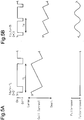
- Fig. 5A shows a case in which the outlet temperature Tout is less than the preset temperature Tth
- Fig. 5B shows a case in which the outlet temperature Tout is greater than or equal to the preset temperature Tth.
- the CPU 72 sets the switching frequency to the low-temperature frequency fL and operates the switching element 62.
- the duty cycle D1 is a value (for example, 80%) that keeps the electromagnetic control valve 26 closed when the switching frequency is the low-temperature frequency fL.
- the CPU 72 activates the switching element 62, the amount of current flowing through the coil 55b gradually increases.
- the CPU 72 deactivates the switching element 62, the amount of current flowing through the coil 55b gradually decreases.
- the duty cycle D when the duty cycle D is large to some extent, the switching element 62 becomes activated before the amount of current flowing through the coil 55b becomes zero. Thus, current needs to continuously flow through the coil 55b.
- the electromagnet 55 produces a larger electromagnetic force that attracts the valve body 53 in the valve-closing direction when a large amount of current flows through the coil 55b than when a small amount of current flows through the coil 55b.
- the switching element 62 when the switching element 62 is activated and deactivated, the amount of current flowing through the coil 55b gradually increases and decreases in a repeated manner.
- the minimum value of current flowing through the coil 55b is larger when the maximum value of current flowing through the coil 55b is large than when the maximum value of current flowing through the coil 55b is small. This lengthens the period during which the electromagnetic control valve 26 can be closed.
- the time during which activation is performed is further lengthened even in the same duty cycle by reducing the switching frequency fduty to the low-temperature frequency fL.
- the electromagnetic control valve 26 can be continuously closed for a period longer than a switching cycle TL, during which the outlet temperature Tout is less than the preset temperature Tth. This sufficiently limits the emission of heat generated in the internal combustion engine 10 to, for example, the heater core 22 or the ATF warmer 24.
- the switching frequency fduty is set to the normal frequency fH. Since the normal frequency fH is higher than the low-temperature frequency fL, the activation time of the switching element 62 is shortened even in the same duty cycle. Consequently, the maximum value of current flowing through the coil 55b is small.
- the amount of heat generated in the coil 55b is proportional to the square of the amount of current flowing through the coil 55b.
- the outlet temperature Tout When the outlet temperature Tout is greater than or equal to the preset temperature Tth, the temperature of the electromagnetic control valve 26 tends to be high. Thus, when the amount of heat generated in the coil 55b is excessively large, wearing of the electromagnetic control valve 26 becomes noticeable. This may lower the durability.
- the outlet temperature Tout is greater than or equal to the preset temperature Tth, there is no issue for keeping the electromagnetic control valve 26 closed. Further, a request is issued for setting a relatively large average open degree, which is achieved by repeatedly opening and closing the electromagnetic control valve 26. This prevents decreases in the controllability of the flow rate that occur when the switching frequency fduty is set to the normal frequency fH.
- setting the switching frequency fduty to the normal frequency fH when the outlet temperature Tout is greater than or equal to the preset temperature Tth prevents excessive increases in the temperature of the electromagnetic control valve 26 while preventing decreases in the controllability for the requested flow rate Qw*.
- the rotational speed NE is greater than or equal to a target rotation speed during idling and less than or equal to a preset rotation speed (for example, 3000 rpm).
- the correspondence between the matters in the above-described embodiment and the matters described in the section SUMMARY is as follows. Hereinafter, the correspondence relationship is shown for every number in the example described in the section SUMMARY.
- the operation process corresponds to the processes of S16 to S26.
- the requested flow rate Qw1* is small. Consequently, when the process of S24 is performed, the duty cycle D has a large value.
- the frequency varying process corresponds to the processes of S10 to S14.
- the "duty cycle, which keeps the electromagnetic control valve closed" corresponds to the duty cycle D1 shown in Fig. 5 .
- the configuration of Example 4 corresponds to the process of S24.
- the requested flow rate Qw1* does not have to be inversely proportional to the difference between the target outlet temperature Tout* and the inlet temperature Tin.
- the base value of the flow rate proportional to the heat quantity Q may be corrected with an operation amount for performing feedback control for the outlet temperature Tout to the target outlet temperature Tout*.
- the heat quantity Q is calculated based on the intake air amount Ga.
- the heat quantity Q may be calculated based on the injection amount per unit of time.
- the low-temperature frequency fL when the outlet temperature Tout is less than the preset temperature Tth, the low-temperature frequency fL is used.
- the inlet temperature Tin when the inlet temperature Tin is less than the preset temperature Tth, the low-temperature frequency fL may be used.
- a sensor that detects the temperature of the inner passage 12 instead of using the inlet temperature Tin and the outlet temperature Tout, for example, a sensor that detects the temperature of the inner passage 12 may be employed. In this case, when the detection value is less than the preset temperature Tth, the low-temperature frequency fL may be used.
- a first preset temperature TthH and a second preset temperature TthL may be used to perform switching between the low-temperature frequency fL and the normal frequency fH.
- the second preset temperature TthL is lower than the first preset temperature TthH.
- the switching frequency fduty simply needs to be switched to the normal frequency fH when the water temperature reaches the first preset temperature TthH, and the switching frequency fduty simply needs to be switched from the normal frequency fH to the low-temperature frequency fL when the water temperature becomes less than the second preset temperature TthL.
- the thermostat 44 which is mechanical, is used to open the electromagnetic control valve 26 with the melting point of wax.
- a device capable of performing opening/closing control through electronic operation may be used. Even in this case, in order to dissipate the heat of coolant using the radiator 42, it is desired that the preset temperature Tth be lower than the predetermined temperature Tsm, at which the thermostat 44 opens.
- the electromagnetic control valve 26 includes the coil spring 54, which produces elastic force acting in the valve-closing direction.
- the electromagnetic control valve 26 may include a coil spring that produces elastic force acting in the valve-opening direction. In this case, even when the internal combustion engine 10 is not running, the electromagnetic control valve 26 is open as long as electromagnetic force acts.
- the cooling controller does not have to include the CPU 72 and the ROM 74 to execute software processing.
- at least part of the processes executed by the software in the above-described embodiment may be executed by hardware circuits dedicated to executing these processes (such as ASIC). That is, the cooling controller may be modified as long as it has any one of the following configurations (a) to (c): (a) A configuration including a processor that executes all of the above-described processes according to programs and a program storage device such as a ROM that stores the programs; (b) A configuration including a processor and a program storage device that execute part of the above-described processes according to the programs and a dedicated hardware circuit that executes the remaining processes; and (c) A configuration including a dedicated hardware circuit that executes all of the above-described processes.
- a plurality of software processing circuits each including a processor and a program storage device and a plurality of dedicated hardware circuits may be provided. That is, the above processes may be executed in any manner as long as the processes are executed by processing circuitry that includes at least one of a set of one or more software processing circuits and a set of one or more dedicated hardware circuits.
Landscapes
- Engineering & Computer Science (AREA)
- Chemical & Material Sciences (AREA)
- Combustion & Propulsion (AREA)
- Mechanical Engineering (AREA)
- General Engineering & Computer Science (AREA)
- Combined Controls Of Internal Combustion Engines (AREA)
- Electrical Control Of Air Or Fuel Supplied To Internal-Combustion Engine (AREA)
Abstract
Description
- The following description relates to a cooling controller and a control method for a cooling device including an inner passage that circulates coolant in an internal combustion engine and an outer passage connected to the inner passage and located outside the internal combustion engine, in which the inner passage and the outer passage configure a loop.
- Japanese Laid-Open Patent Publication No.
2017-31909 - The inventors attempted to expedite warm-up of the internal combustion engine after cold-starting the engine by closing the electromagnetic control valve to open the loop while circulating coolant in the internal combustion engine with an engine-driven pump. In this case, current flows through the coil of the electromagnetic control valve in order to keep the electromagnetic control valve closed. As a result, after the internal combustion engine is warmed up, the coil will be overheated.
- It is an objective of the present disclosure to provide a cooling controller that reduces the amount of heat generated in a coil when the temperature of the internal combustion engine is high while sufficiently reducing the average value of the cross-sectional flow area of the outer passage with an electromagnetic control valve when the temperature of the internal combustion engine is low.
- This Summary is provided to introduce a selection of concepts in a simplified form that are further described below in the Detailed Description. This Summary is not intended to identify key features or essential features of the claimed subject matter, nor is it intended to be used as an aid in determining the scope of the claimed subject matter.
- The examples of the present disclosure will now be described.
- Example 1: A cooling controller adapted for use in a cooling device is provided. The cooling device includes an inner passage that circulates coolant in an internal combustion engine, an outer passage located outside the internal combustion engine and connected to the inner passage, the inner passage and the outer passage configuring a loop, an engine-driven pump configured to circulate the coolant in the loop when driven by rotational power of a crankshaft of the internal combustion engine, an electromagnetic control valve configured to adjust a cross-sectional flow area of the outer passage, the electromagnetic control valve being open in a non-energized state when the engine-driven pump is driven, and a driving circuit configured to regulate current flowing through the electromagnetic control valve by activating and deactivating a switching element. The cooling controller includes a processing circuit configured to execute an operation process for operating, when the engine-driven pump is driven, the switching element by setting a duty cycle of an activation time to a switching cycle, which is a reciprocal of a switching frequency of the switching element, to be a larger value in a case in which a temperature of the internal combustion engine is low than in a case in which the temperature of the internal combustion engine is high. The processing circuit is also configured to execute a cycle varying process for setting the switching cycle to be longer when the temperature of the internal combustion engine is less than a preset temperature than when the temperature of the internal combustion engine is greater than or equal to the preset temperature.
- Even if the duty cycle is the same, the activation time is longer when the switching cycle is long than when the switching cycle is short. Since current flowing through the coil of the electromagnetic control valve is larger when the activation time is long than when the activation time is short, the force that closes the electromagnetic control valve is strong. Thus, when the outlet temperature is less than the preset temperature, it is desired that the switching cycle be lengthened to set a sufficiently small average value of the cross-sectional flow area of the outer passage by the electromagnetic control valve. However, in this case, when the temperature of the internal combustion engine is high, the temperature of the surroundings of the coil is high. This limits expedition of the heat dissipation of the coil and thus may overheat the coil. In the above-described configuration, a longer switching cycle is set when the outlet temperature is less than the preset temperature than when the outlet temperature is greater than or equal to the preset temperature. This limits the amount of heat generated by the coil when the temperature of the internal combustion engine is high while setting a sufficiently small average value of the cross-sectional flow area of the outer passage by the electromagnetic control valve when the temperature of the internal combustion engine is low.
- Example 2: In the cooling controller according to example 1, a period longer than the switching cycle set through the cycle varying process when the temperature of the internal combustion engine is less than the preset temperature is referred to as a predetermined period. The switching cycle set through the cycle varying process when the temperature of the internal combustion engine is greater than or equal to the preset temperature is referred to as a first switching cycle. The switching cycle set through the cycle varying process when the temperature of the internal combustion engine is less than the preset temperature is referred to as a second switching cycle. The duty cycle is set such that a duty cycle that keeps the electromagnetic control valve closed over the predetermined period during the second switching cycle cannot keep the electromagnetic control valve closed over the predetermined period during the first switching cycle.
- In the above-described configuration, as compared to when the duty cycle is set to keep the electromagnetic control valve closed over the predetermined period using the switching cycle, which is set through the cycle varying process in a case in which the outlet temperature is greater than or equal to the preset temperature, the first switching cycle can be shortened when the outlet temperature is greater than or equal to the preset temperature. This reduces the amount of heat generated by the coil.
- Example 3: In the cooling controller according to example 1 or 2, the cooling device further includes a radiator passage connected to the inner passage, the radiator passage being separate from the outer passage and connected to the radiator, and a thermostat configured to connect and disconnect the inner passage to and from the radiator. The thermostat is configured to allow the inner passage and the radiator to be connected to each other when the temperature of the internal combustion engine is greater than or equal to a predetermined temperature. The preset temperature is lower than the predetermined temperature.
- When the thermostat opens, the temperature of the internal combustion engine is high. Thus, when the switching cycle is lengthened until the thermostat opens, the coil may be overheated. In the configuration of Example 3, the switching cycle is switched before the thermostat opens. Thus, as compared to when the switching cycle is switched after the thermostat opens, overheating of the coil is limited.
- Example 4: In the cooling controller according to any one of examples 1 to 3, the operation process includes a process for setting, when the temperature of the internal combustion engine is less than the preset temperature, the duty cycle to be smaller in a case in which a large amount of fuel is supplied into a combustion chamber of the internal combustion engine per unit of time than in a case in which a small amount of fuel is supplied.
- In a case in which circulation of coolant in the inner passage is excessively restricted even when the temperature of the internal combustion engine is low, coolant may boil in the inner passage, where the small cross-sectional flow area is small, such as in a drilled passage. In the configuration of Example 4, when the amount of fuel is large and the amount of heat generated in the internal combustion engine is large, the duty cycle is shortened, thereby setting a large average value of the cross-sectional flow area of the outer passage, which is adjusted by the electromagnetic control valve. This increases the circulation amount of coolant and thus limits an excessive increase in the temperature of the inner passage on a local level.
- Example 5: A control method for a cooling device is provided. The cooling device including an inner passage that circulates coolant in an internal combustion engine, an outer passage located outside the internal combustion engine and connected to the inner passage, the inner passage and the outer passage configuring a loop, an engine-driven pump configured to circulate the coolant in the loop when driven by rotational power of a crankshaft of the internal combustion engine, an electromagnetic control valve configured to adjust a cross-sectional flow area of the outer passage, the electromagnetic control valve being open in a non-energized state when the engine-driven pump is driven, and a driving circuit configured to regulate current flowing through the electromagnetic control valve by activating and deactivating a switching element. The control method includes operating, when the engine-driven pump is driven, the switching element by setting a duty cycle of an activation time to a switching cycle, which is a reciprocal of a switching frequency of the switching element, to be a larger value in a case in which a temperature of the internal combustion engine is low than in a case in which the temperature of the internal combustion engine is high. The control method also includes setting the switching cycle to be longer when the temperature of the internal combustion engine is less than a preset temperature than when the temperature of the internal combustion engine is greater than or equal to the preset temperature.
- Other features and aspects will be apparent from the following detailed description, the drawings, and the claims.
-
-
Fig. 1 is a diagram showing a cooling controller and a cooling device according to an embodiment. -
Fig. 2 is a diagram showing the electromagnetic control valve and the driving circuit in the cooling device ofFig. 1 . -
Fig. 3A is a diagram showing the electromagnetic control valve ofFig. 2 when open. -
Fig. 3B is a diagram showing the electromagnetic control valve ofFig. 2 when closed. -
Fig. 4 is a flowchart illustrating a procedure for processes executed by the cooling controller shown inFig. 1 . -
Fig. 5A is a time chart illustrating an effect of the cooling controller shown inFig. 1 . -
Fig. 5B is a time chart illustrating an effect of the cooling controller shown inFig. 1 . - Throughout the drawings and the detailed description, the same reference numerals refer to the same elements. The drawings may not be to scale, and the relative size, proportions, and depiction of elements in the drawings may be exaggerated for clarity, illustration, and convenience.
- This description provides a comprehensive understanding of the methods, apparatuses, and/or systems described. Modifications and equivalents of the methods, apparatuses, and/or systems described are apparent to one of ordinary skill in the art. Sequences of operations are exemplary, and may be changed as apparent to one of ordinary skill in the art, with the exception of operations necessarily occurring in a certain order. Descriptions of functions and constructions that are well known to one of ordinary skill in the art may be omitted.
- Exemplary embodiments may have different forms, and are not limited to the examples described. However, the examples described are thorough and complete, and convey the full scope of the disclosure to one of ordinary skill in the art.
- A cooling controller and a control method for a cooling device according to an embodiment will now be described with reference to the drawings.
-
Fig. 1 shows a spark-ignitioninternal combustion engine 10. Theinternal combustion engine 10 includes aninner passage 12 that circulates coolant in theinternal combustion engine 10. Theinner passage 12 is connected to anouter passage 14 located outside theinternal combustion engine 10. Theinner passage 12 and theouter passage 14 configure a loop. Theouter passage 14 branches into athrottle passage 14a, aheater core passage 14b, and awarmer passage 14c. Thethrottle passage 14a includes athrottle body 20 serving as a passage where the temperature of the throttle valve is adjusted with coolant. Theheater core passage 14b includes aheater core 22, which is a heat exchanger. In theheater core 22, the heat of coolant in theinternal combustion engine 10 is applied to air supplied into the passenger compartment. Theheater core passage 14b includes anelectromagnetic control valve 26 on the downstream side of theheater core 22. Theelectromagnetic control valve 26 adjusts the cross-sectional flow area of theheater core passage 14b. Thewarmer passage 14c includes an automatic transmission fluid (ATF) warmer 24, which is a heat exchanger. The ATF warmer 24 is configured to adjust the temperature of an ATF, which is hydraulic oil for an automatic transmission, with the heat of coolant. Thewarmer passage 14c includes anelectromagnetic control valve 28 on the downstream side of the ATF warmer 24. Theelectromagnetic control valve 28 adjusts the cross-sectional flow area of thewarmer passage 14c. - The
electromagnetic control valve 26 is driven by a drivingcircuit 30. Theelectromagnetic control valve 28 is driven by a drivingcircuit 32. - The
inner passage 12 is further connected to aradiator passage 40. The loop is also configured by theinner passage 12 and theradiator passage 40. Theradiator passage 40 is connected to aradiator 42 that exchanges heat with the surrounding air to dissipate the heat of the coolant in theinternal combustion engine 10. - The downstream sides of the
throttle passage 14a, theheater core passage 14b, and thewarmer passage 14c merge with one another and connect to theinner passage 12 via athermostat 44 and an engine-drivenpump 46. The downstream side of theradiator passage 40 is also connected to theinner passage 12 via thethermostat 44 and the engine-drivenpump 46. - The
thermostat 44 is a three-way valve that guides the downstream sides of theouter passage 14 and theradiator passage 40 to theinner passage 12. Thethermostat 44 accommodates wax. When the wax expands in accordance with the temperature of coolant in the vicinity of thethermostat 44, the state of the valve changes. More specifically, when the temperature of coolant (water temperature THW) is less than a predetermined temperature Tsm (for example, greater than or equal to 90°C), the cross-sectional flow area of the path through which coolant flows from theradiator passage 40 to theinner passage 12 is set to zero by thethermostat 44, and the cross-sectional flow area of the path through which coolant flows from theouter passage 14 to theinner passage 12 is set to be larger than zero by thethermostat 44. Further, when the water temperature THW is greater than or equal to the predetermined temperature Tsm, the cross-sectional flow area of the path through which coolant flows from theradiator passage 40 to theinner passage 12 and the cross-sectional flow area of the path through which coolant flows from theouter passage 14 to theinner passage 12 are both set to be larger than zero by thethermostat 44. - The engine-driven
pump 46 is driven by the rotational power of the crankshaft of theinternal combustion engine 10. The engine-drivenpump 46 is an engine-driven water pump that causes coolant drawn in from the suction port to be discharged out of the discharge port. The engine-drivenpump 46 rotates in synchronization with rotation of the crankshaft. Thus, the discharge amount per unit of time is larger when the rotational speed of the crankshaft is high than when the rotational speed of the crankshaft is low. - The cooling device of the
internal combustion engine 10 is configured by theinner passage 12, theouter passage 14, thethrottle body 20, theheater core 22, the ATF warmer 24, theelectromagnetic control valves circuits radiator passage 40, theradiator 42, thethermostat 44, and the engine-drivenpump 46. -
Fig. 2 shows the structures of theelectromagnetic control valve 26 and the drivingcircuit 30. Theelectromagnetic control valve 28 and the drivingcircuit 32 have the same structures and thus will not be described. - As shown in
Fig, 2 , theelectromagnetic control valve 26 includes ahousing 50. Thehousing 50 includes acoolant passage 51 through which coolant passes. Thecoolant passage 51 includes avalve seat 52 and avalve body 53. - The
housing 50 accommodates acoil spring 54 that constantly produces elastic force in a direction in which thevalve body 53 moves toward the valve seat 52 (valve-closing direction, i.e., upward direction inFig. 2 ). Thehousing 50 also includes anelectromagnet 55. Theelectromagnet 55 includes acore 55a made of a soft magnetic material and acoil 55b shaped to surround thecore 55a. - The
coil 55b is connected to the drivingcircuit 30. The drivingcircuit 30 includes a switching element 62. The switching element 62 is activated and deactivated to open and close a loop configured by the switching element 62, thecoil 55b, and abattery 60. Further, the drivingcircuit 30 includes adiode 64 of which the cathode is connected to the positive electrode terminal of thebattery 60. Thediode 64 and thecoil 55b configure a closed loop. - When the switching element 62 is activated, the loop configured by the
battery 60, the switching element 62, and thecoil 55b is closed. This gradually increases current flowing through thecoil 55b. When the switching element 62 is deactivated, current flows through thecoil 55b via the loop configured by thediode 64 and thecoil 55b. This gradually decreases the amount of the current. When current flows through thecoil 55b, theelectromagnet 55 produces magnetic force that attracts thevalve body 53 in the valve-closing direction. - The
electromagnetic control valve 26 is coupled to theheater core passage 14b so that coolant flows in a direction opposite to the direction in which thecoil spring 54 applies elastic force to thevalve body 53 in thecoolant passage 51. When the engine-drivenpump 46 is driven, coolant produces pressure acting in a direction in which thevalve body 53 moves away from the valve seat 52 (valve-opening direction, i.e., downward direction inFig. 2 ). Thus, when thecoil 55b is not energized, theelectromagnetic control valve 26 opens as shown inFig. 3A . - When the
coil 55b is energized, theelectromagnet 55 produces magnetic force that attracts thevalve body 53 in the valve-closing direction. Thus, as shown inFig. 3B , the elastic force of thecoil spring 54 and the attraction force of theelectromagnet 55 hold thevalve body 53 on thevalve seat 52 against the pressure of coolant flowing into thecoolant passage 51. That is, theelectromagnetic control valve 26 closes. -
Fig. 1 shows acontroller 70 that controls the cooling device by operating theelectromagnetic control valves controller 70 controls torque or exhaust component, which is the control amount of theinternal combustion engine 10. Thecontroller 70 executes an air-fuel ratio control as control of the exhaust component. The air-fuel ratio control is to set the amount of fuel injected in accordance with the amount of fresh air filling the combustion chamber. - In order to control the control amount, the
controller 70 refers to an inlet temperature Tin, an outlet temperature Tout, an intake air amount Ga, and an output signal Scr of acrank angle sensor 86. The inlet temperature Tin is the temperature of coolant on the inlet side of theinner passage 12 detected by aninlet temperature sensor 80. The outlet temperature Tout is the temperature of coolant on the outlet side of theinner passage 12 detected by anoutlet temperature sensor 82. The intake air amount Ga is detected by anairflow meter 84. Thecontroller 70 includes aCPU 72, aROM 74, and apower circuit 76 that supplies power to elements in thecontroller 70. Thecontroller 70 controls the above-described control amount by executing a program stored in theROM 74 with theCPU 72. -
Fig. 4 shows a procedure for processes of operating theelectromagnetic control valve 26 among the processes executed by thecontroller 70. The processes illustrated inFig. 4 are implemented when theCPU 72 repeatedly executes the program stored in theROM 74, for example, in a predetermined cycle. In the following description, the step number of each process is represented by a number in front of which the character S is given. - In a series of processes shown in
Fig. 4 , theCPU 72 first determines whether the outlet temperature Tout is greater than or equal to a preset temperature Tth (S10). This process is to determine whether expediting warm-up of theinternal combustion engine 10 is required. The preset temperature Tth is lower than the predetermined temperature Tsm (for example, 60°C to 80°C). When determining that the outlet temperature Tout is greater than or equal to the preset temperature Tth (S10: YES), theCPU 72 substitutes a normal frequency fH into a switching frequency fduty, which is the reciprocal of a switching cycle (PWM cycle) during which the switching element 62 is activated and deactivated (S12). When determining that the outlet temperature Tout is less than the preset temperature Tth (S10: NO), theCPU 72 substitutes a low-temperature frequency fL into the switching frequency fduty (S14). The low-temperature frequency fL is lower than the normal frequency fH. - When completing the process of S12 or S14, the
CPU 72 calculates a heat quantity Q generated per unit of time in the combustion chamber of theinternal combustion engine 10 based on the intake air amount Ga (S16). TheCPU 72 calculates the heat quantity Q to be a larger value when the intake air amount Ga is large than when the intake air amount Ga is small. The intake air amount Ga is a parameter correlated with the amount of fresh air filling the combustion chamber per unit of time. More specifically, theROM 74 already stores map data in which the intake air amount Ga is an input variable and the heat quantity Q is an output variable, and theCPU 72 uses this map data to calculate the heat quantity Q. - Map data refers to a set of data including the discrete values of input invariables and the values of output variables that respectively correspond to the values of the input variables. In the calculation using this data map, i.e., in map calculation, for example, when the value of an input variable coincides with any one of the input variables of a map data, the value of the corresponding output variable of the map data is treated as a calculation result. Further, when such a coincidence does not occur, a value obtained through interpolation of the output variables included in the map data is treated as a calculation result.
- Subsequently, the
CPU 72 calculates a requested flow rate Qw1*, which is the flow rate of coolant flowing through theelectromagnetic control valve 26. The requested flow rate Qw1* is requested to control the outlet temperature Tout to a target outlet temperature Tout* (S18). TheCPU 72 calculates the requested flow rate Qw1* to be a larger value when the heat quantity Q is large than when the heat quantity Q is small. Further, theCPU 72 calculates the requested flow rate Qw1* to be a smaller value when the target outlet temperature Tout* exceeds the inlet temperature Tin to a large extent than when the target outlet temperature Tout* exceeds the inlet temperature Tin to a small extent. More specifically, the following equation is used to calculate the requested flow rate Qw1*. The target outlet temperature Tout* is higher than the preset temperature Tth.

- When the value of the right-hand side of the equation is less than or equal to a preset value, the
CPU 72 sets the requested flow rate Qw1* to zero. Even if the outlet temperature Tout is less than the preset temperature Tth, the value of the right-hand side of the equation is greater than the preset value when the intake air amount Ga is large. This is because even if the outlet temperature Tout is less than the preset temperature Tth, theinternal combustion engine 10 generates a large amount of heat per unit of time when the intake air amount Ga is large. Thus, when theelectromagnetic control valve 26 is kept closed, coolant may boil in theinner passage 12, where the small cross-sectional flow area is small, such as in a drilled passage. In order to prevent such boiling, even if the outlet temperature Tout is less than the preset temperature Tth, theCPU 72 calculates the requested flow rate Qw1* to a value larger than zero when the intake air amount Ga is large. - Further, the
CPU 72 calculates a requested flow rate Qw2* in accordance with a request for heating a vehicle (S20). TheCPU 72 calculates the requested flow rate Qw2* to a larger value when the heating request is large than when the heating request is small (S20). - Then, the
CPU 72 substitutes the larger one of the requested flow rate Qw1* and the requested flow rate Qw2* into a requested flow rate Qw* (S22). Subsequently, theCPU 72 calculates a duty cycle D of the switching element 62, which is used to control the flow rate of coolant flowing through theelectromagnetic control valve 26 to the requested flow rate Qw* (S24). The duty cycle D is the ratio of the activation time to the switching cycle. TheCPU 72 calculates the duty cycle D to a larger value in order to set a longer period during which theelectromagnetic control valve 26 closes when the requested flow rate Qw1* is small than when the requested flow rate Qw1* is large. In addition, theCPU 72 calculates the duty cycle D to a larger value when a rotational speed NE is high than when the rotational speed NE is low. This calculation is performed for the following reason. The amount of water discharged by the engine-drivenpump 46 per unit of time is larger when the rotational speed NE is high than when the rotational speed NE is low, thereby increasing the force by coolant to open thevalve body 53. The rotational speed NE is calculated by theCPU 72 based on the output signal Scr. - In detail, the
ROM 74 already stores map data in which the requested flow rate Qw* and the rotational speed NE are input variables and the duty cycle D is an output variable, and theCPU 72 uses this map data to calculate the duty cycle D. An output variable aij (i = 1 to m, j = 1 to n) of the map data is demonstrated inFig. 4 . A variable i specifies a value of the rotational speed NE, and a variable j specifies a value of the requested flow rate Qw*.Fig. 4 shows that j is less than k, i.e., the output variable aij when the requested flow rate Qw* is small is larger than an output variable aik when the requested flow rate Qw* is large. - The
CPU 72 activates and deactivates the switching element 62 in accordance with the duty cycle D (S26). - When completing the process of S26, the
CPU 72 ends the series of processes shown inFig. 4 . - The processes for operating the switching element of the
electromagnetic control valve 28 are performed in the same manner as the processes shown inFig. 4 . In the process of S20, the requested flow rate Qw2* is calculated in accordance with a request of the heat quantity of the ATF warmer 24 instead of the heating request of the vehicle. - The operation of the present embodiment will now be described.
-
Fig. 5A shows a case in which the outlet temperature Tout is less than the preset temperature Tth, andFig. 5B shows a case in which the outlet temperature Tout is greater than or equal to the preset temperature Tth. - As shown in
Fig. 5A , when the outlet temperature Tout is less than the preset temperature Tth, theCPU 72 sets the switching frequency to the low-temperature frequency fL and operates the switching element 62. The duty cycle D1 is a value (for example, 80%) that keeps theelectromagnetic control valve 26 closed when the switching frequency is the low-temperature frequency fL. When theCPU 72 activates the switching element 62, the amount of current flowing through thecoil 55b gradually increases. Subsequently, when theCPU 72 deactivates the switching element 62, the amount of current flowing through thecoil 55b gradually decreases. As shown inFigs. 5A and 5B , when the duty cycle D is large to some extent, the switching element 62 becomes activated before the amount of current flowing through thecoil 55b becomes zero. Thus, current needs to continuously flow through thecoil 55b. - A larger amount of current flows through the
coil 55b when the switching element 62 is activated for a long period of time than when the switching element 62 is activated for a short period of time. Theelectromagnet 55 produces a larger electromagnetic force that attracts thevalve body 53 in the valve-closing direction when a large amount of current flows through thecoil 55b than when a small amount of current flows through thecoil 55b. As shown inFigs. 5A and 5B , when the switching element 62 is activated and deactivated, the amount of current flowing through thecoil 55b gradually increases and decreases in a repeated manner. Thus, the minimum value of current flowing through thecoil 55b is larger when the maximum value of current flowing through thecoil 55b is large than when the maximum value of current flowing through thecoil 55b is small. This lengthens the period during which theelectromagnetic control valve 26 can be closed. - Accordingly, in the present embodiment, when the temperature of the
internal combustion engine 10 is low, that is, when warm-up of theinternal combustion engine 10 requires to be expedited, the time during which activation is performed is further lengthened even in the same duty cycle by reducing the switching frequency fduty to the low-temperature frequency fL. This allows the valve-closing period of theelectromagnetic control valve 26 to be easily obtained. In a case in which the duty cycle D1 is employed, theelectromagnetic control valve 26 can be continuously closed for a period longer than a switching cycle TL, during which the outlet temperature Tout is less than the preset temperature Tth. This sufficiently limits the emission of heat generated in theinternal combustion engine 10 to, for example, theheater core 22 or the ATF warmer 24. - In the present embodiment, as shown in
Fig. 5B , when the outlet temperature Tout is greater than or equal to the preset temperature Tth, the switching frequency fduty is set to the normal frequency fH. Since the normal frequency fH is higher than the low-temperature frequency fL, the activation time of the switching element 62 is shortened even in the same duty cycle. Consequently, the maximum value of current flowing through thecoil 55b is small. The amount of heat generated in thecoil 55b is proportional to the square of the amount of current flowing through thecoil 55b. Thus, when the outlet temperature Tout is greater than or equal to the preset temperature Tth, the amount of heat generated in thecoil 55b is reduced by setting the switching frequency fduty to the normal frequency fH. When the outlet temperature Tout is greater than or equal to the preset temperature Tth, the temperature of theelectromagnetic control valve 26 tends to be high. Thus, when the amount of heat generated in thecoil 55b is excessively large, wearing of theelectromagnetic control valve 26 becomes noticeable. This may lower the durability. When the outlet temperature Tout is greater than or equal to the preset temperature Tth, there is no issue for keeping theelectromagnetic control valve 26 closed. Further, a request is issued for setting a relatively large average open degree, which is achieved by repeatedly opening and closing theelectromagnetic control valve 26. This prevents decreases in the controllability of the flow rate that occur when the switching frequency fduty is set to the normal frequency fH. - Accordingly, in the present embodiment, setting the switching frequency fduty to the normal frequency fH when the outlet temperature Tout is greater than or equal to the preset temperature Tth prevents excessive increases in the temperature of the
electromagnetic control valve 26 while preventing decreases in the controllability for the requested flow rate Qw*. - In the present embodiment, as shown in
Fig. 5B , when the switching frequency fduty is set to the normal frequency fH, the duty cycle D1 does not keep theelectromagnetic control valve 26 closed. Thus, as compared to when the duty cycle D1 keeps theelectromagnetic control valve 26 closed, the maximum value of current flowing through thecoil 55b is set to a minimum value. Consequently, the amount of heat generated in thecoil 55b is further reduced. - It is assumed in
Figs. 5A and 5B that the rotational speed NE is greater than or equal to a target rotation speed during idling and less than or equal to a preset rotation speed (for example, 3000 rpm). - The correspondence between the matters in the above-described embodiment and the matters described in the section SUMMARY is as follows. Hereinafter, the correspondence relationship is shown for every number in the example described in the section SUMMARY. [1] The operation process corresponds to the processes of S16 to S26. In the process of S18, when the inlet temperature Tin is low, the requested flow rate Qw1* is small. Consequently, when the process of S24 is performed, the duty cycle D has a large value. The frequency varying process corresponds to the processes of S10 to S14. [2] The "duty cycle, which keeps the electromagnetic control valve closed" corresponds to the duty cycle D1 shown in
Fig. 5 . [4] The configuration of Example 4 corresponds to the process of S24. - The above-described embodiments may be modified as described below. The above-described embodiments and the following modifications may be implemented in combination with each other as long as technical contradiction does not occur.
- The requested flow rate Qw1* does not have to be inversely proportional to the difference between the target outlet temperature Tout* and the inlet temperature Tin. Instead, for example, the base value of the flow rate proportional to the heat quantity Q may be corrected with an operation amount for performing feedback control for the outlet temperature Tout to the target outlet temperature Tout*.
- In the above-described embodiment, the heat quantity Q is calculated based on the intake air amount Ga. Instead, for example, the heat quantity Q may be calculated based on the injection amount per unit of time.
- In the above-described embodiment, when the outlet temperature Tout is less than the preset temperature Tth, the low-temperature frequency fL is used. Instead, for example, when the inlet temperature Tin is less than the preset temperature Tth, the low-temperature frequency fL may be used. Alternatively, instead of using the inlet temperature Tin and the outlet temperature Tout, for example, a sensor that detects the temperature of the
inner passage 12 may be employed. In this case, when the detection value is less than the preset temperature Tth, the low-temperature frequency fL may be used. - Additionally, for example, in order to prevent the occurrence of hunting of switching between the low-temperature frequency fL and the normal frequency fH, a first preset temperature TthH and a second preset temperature TthL may be used to perform switching between the low-temperature frequency fL and the normal frequency fH. The second preset temperature TthL is lower than the first preset temperature TthH. More specifically, the switching frequency fduty simply needs to be switched to the normal frequency fH when the water temperature reaches the first preset temperature TthH, and the switching frequency fduty simply needs to be switched from the normal frequency fH to the low-temperature frequency fL when the water temperature becomes less than the second preset temperature TthL.
- In the above-described embodiment, the
thermostat 44, which is mechanical, is used to open theelectromagnetic control valve 26 with the melting point of wax. Instead, for example, a device capable of performing opening/closing control through electronic operation may be used. Even in this case, in order to dissipate the heat of coolant using theradiator 42, it is desired that the preset temperature Tth be lower than the predetermined temperature Tsm, at which thethermostat 44 opens. - In the above-described embodiment, the
electromagnetic control valve 26 includes thecoil spring 54, which produces elastic force acting in the valve-closing direction. Instead, for example, theelectromagnetic control valve 26 may include a coil spring that produces elastic force acting in the valve-opening direction. In this case, even when theinternal combustion engine 10 is not running, theelectromagnetic control valve 26 is open as long as electromagnetic force acts. - The cooling controller does not have to include the
CPU 72 and theROM 74 to execute software processing. For example, at least part of the processes executed by the software in the above-described embodiment may be executed by hardware circuits dedicated to executing these processes (such as ASIC). That is, the cooling controller may be modified as long as it has any one of the following configurations (a) to (c): (a) A configuration including a processor that executes all of the above-described processes according to programs and a program storage device such as a ROM that stores the programs; (b) A configuration including a processor and a program storage device that execute part of the above-described processes according to the programs and a dedicated hardware circuit that executes the remaining processes; and (c) A configuration including a dedicated hardware circuit that executes all of the above-described processes. A plurality of software processing circuits each including a processor and a program storage device and a plurality of dedicated hardware circuits may be provided. That is, the above processes may be executed in any manner as long as the processes are executed by processing circuitry that includes at least one of a set of one or more software processing circuits and a set of one or more dedicated hardware circuits. - Various changes in form and details may be made to the examples above without departing from the spirit and scope of the claims and their equivalents. The examples are for the sake of description only, and not for purposes of limitation. Descriptions of features in each example are to be considered as being applicable to similar features or aspects in other examples. Suitable results may be achieved if sequences are performed in a different order, and/or if components in a described system, architecture, device, or circuit are combined differently, and/or replaced or supplemented by other components or their equivalents. The scope of the disclosure is not defined by the detailed description, but by the claims and their equivalents. All variations within the scope of the claims and their equivalents are included in the disclosure.
Claims (5)
- A cooling controller adapted for use in a cooling device, the cooling device including
an inner passage (12) that circulates coolant in an internal combustion engine (10),
an outer passage (14) located outside the internal combustion engine (10) and connected to the inner passage (12), the inner passage (12) and the outer passage (14) configuring a loop,
an engine-driven pump (46) configured to circulate the coolant in the loop when driven by rotational power of a crankshaft of the internal combustion engine (10),
an electromagnetic control valve (26) configured to adjust a cross-sectional flow area of the outer passage (14), the electromagnetic control valve (26) being open in a non-energized state when the engine-driven pump (46) is driven, and
a driving circuit (30) configured to regulate current flowing through the electromagnetic control valve (26) by activating and deactivating a switching element (62), wherein
the cooling controller comprises a processing circuit configured to execute:an operation process for operating, when the engine-driven pump (46) is driven, the switching element (62) by setting a duty cycle of an activation time to a switching cycle, which is a reciprocal of a switching frequency of the switching element (62), to be a larger value in a case in which a temperature of the internal combustion engine (10) is low than in a case in which the temperature of the internal combustion engine (10) is high; anda cycle varying process for setting the switching cycle to be longer when the temperature of the internal combustion engine (10) is less than a preset temperature than when the temperature of the internal combustion engine (10) is greater than or equal to the preset temperature. - The cooling controller according to claim 1, wherein
a period longer than the switching cycle set through the cycle varying process when the temperature of the internal combustion engine (10) is less than the preset temperature is referred to as a predetermined period,
the switching cycle set through the cycle varying process when the temperature of the internal combustion engine (10) is greater than or equal to the preset temperature is referred to as a first switching cycle,
the switching cycle set through the cycle varying process when the temperature of the internal combustion engine (10) is less than the preset temperature is referred to as a second switching cycle, and
the duty cycle is set such that a duty cycle that keeps the electromagnetic control valve (26) closed over the predetermined period during the second switching cycle cannot keep the electromagnetic control valve (26) closed over the predetermined period during the first switching cycle. - The cooling controller according to claim 1 or 2, wherein
the cooling device further includesa radiator passage (40) connected to the inner passage (12), the radiator passage (40) being separate from the outer passage (14) and connected to the radiator (42), anda thermostat (44) configured to connect and disconnect the inner passage (12) to and from the radiator (42),the thermostat (44) is configured to allow the inner passage (12) and the radiator (42) to be connected to each other when the temperature of the internal combustion engine (10) is greater than or equal to a predetermined temperature, and
the preset temperature is lower than the predetermined temperature. - The cooling controller according to any one of claims 1 to 3, wherein the operation process includes a process for setting, when the temperature of the internal combustion engine (10) is less than the preset temperature, the duty cycle to be smaller in a case in which a large amount of fuel is supplied into a combustion chamber of the internal combustion engine (10) per unit of time than in a case in which a small amount of fuel is supplied.
- A control method for a cooling device, the cooling device including
an inner passage (12) that circulates coolant in an internal combustion engine (10),
an outer passage (14) located outside the internal combustion engine (10) and connected to the inner passage (12), the inner passage (12) and the outer passage (14) configuring a loop,
an engine-driven pump (46) configured to circulate the coolant in the loop when driven by rotational power of a crankshaft of the internal combustion engine (10),
an electromagnetic control valve (26) configured to adjust a cross-sectional flow area of the outer passage (14), the electromagnetic control valve (26) being open in a non-energized state when the engine-driven pump (46) is driven, and
a driving circuit (30) configured to regulate current flowing through the electromagnetic control valve (26) by activating and deactivating a switching element (62), wherein
the control method comprises:operating, when the engine-driven pump (46) is driven, the switching element (62) by setting a duty cycle of an activation time to a switching cycle, which is a reciprocal of a switching frequency of the switching element (62), to be a larger value in a case in which a temperature of the internal combustion engine (10) is low than in a case in which the temperature of the internal combustion engine (10) is high; andsetting the switching cycle to be longer when the temperature of the internal combustion engine (10) is less than a preset temperature than when the temperature of the internal combustion engine (10) is greater than or equal to the preset temperature.
Applications Claiming Priority (1)
| Application Number | Priority Date | Filing Date | Title |
|---|---|---|---|
| JP2018115864A JP7000262B2 (en) | 2018-06-19 | 2018-06-19 | Cooling control device |
Publications (2)
| Publication Number | Publication Date |
|---|---|
| EP3584419A1 true EP3584419A1 (en) | 2019-12-25 |
| EP3584419B1 EP3584419B1 (en) | 2020-09-09 |
Family
ID=66912737
Family Applications (1)
| Application Number | Title | Priority Date | Filing Date |
|---|---|---|---|
| EP19180622.3A Active EP3584419B1 (en) | 2018-06-19 | 2019-06-17 | Cooling controller and control method for cooling device |
Country Status (4)
| Country | Link |
|---|---|
| US (1) | US10961898B2 (en) |
| EP (1) | EP3584419B1 (en) |
| JP (1) | JP7000262B2 (en) |
| CN (1) | CN110617143B (en) |
Cited By (2)
| Publication number | Priority date | Publication date | Assignee | Title |
|---|---|---|---|---|
| CN112576359A (en) * | 2020-11-18 | 2021-03-30 | 潍柴动力股份有限公司 | Low-temperature cooling system, vehicle and control method of low-temperature cooling system |
| CN115217609A (en) * | 2022-06-06 | 2022-10-21 | 广州汽车集团股份有限公司 | Engine thermal management control method and device, electronic equipment and storage medium |
Families Citing this family (2)
| Publication number | Priority date | Publication date | Assignee | Title |
|---|---|---|---|---|
| CN111927615B (en) * | 2020-08-19 | 2021-10-29 | 潍柴动力股份有限公司 | Coolant temperature display method and device |
| DE102021206117A1 (en) * | 2021-06-16 | 2022-12-22 | Zf Friedrichshafen Ag | Traction drive with a cooling system with two cooling circuits |
Citations (4)
| Publication number | Priority date | Publication date | Assignee | Title |
|---|---|---|---|---|
| US4738330A (en) * | 1985-03-22 | 1988-04-19 | Nippondenso Co., Ltd. | Hydraulic drive system for use with vehicle power steering pump |
| JPH01227816A (en) * | 1988-03-07 | 1989-09-12 | Toyota Motor Corp | Rotating speed control device for hydraulically driven cooling fan of internal combustion engine |
| WO2011132530A2 (en) * | 2010-04-19 | 2011-10-27 | Aisin Seiki Kabushiki Kaisha | Vehicle coolant control valve |
| EP3128148A1 (en) * | 2015-08-04 | 2017-02-08 | Toyota Jidosha Kabushiki Kaisha | Cooling liquid circulation device for internal combustion engine |
Family Cites Families (15)
| Publication number | Priority date | Publication date | Assignee | Title |
|---|---|---|---|---|
| JPS62174557A (en) * | 1986-01-25 | 1987-07-31 | Mazda Motor Corp | Vaporized fuel control device for engine |
| JP3809625B2 (en) | 1997-02-28 | 2006-08-16 | ヤマハ発動機株式会社 | Engine-driven heat pump device |
| JP2000027646A (en) | 1998-07-07 | 2000-01-25 | Nidec Tosok Corp | Coolant control device for engine |
| FR2804719B1 (en) | 2000-02-03 | 2002-06-21 | Peugeot Citroen Automobiles Sa | COOLING DEVICE OF A MOTOR VEHICLE ENGINE |
| JP4841772B2 (en) | 2001-09-28 | 2011-12-21 | いすゞ自動車株式会社 | Common rail fuel injection control device |
| JP2009185700A (en) | 2008-02-06 | 2009-08-20 | Fuji Heavy Ind Ltd | Cooling control device for vehicle drive system |
| US20130161547A1 (en) * | 2010-11-12 | 2013-06-27 | Aisin Seiki Kabushiki Kaisha | Control valve |
| JP5257712B2 (en) * | 2011-02-10 | 2013-08-07 | アイシン精機株式会社 | Engine cooling system |
| JP5240403B2 (en) * | 2011-03-18 | 2013-07-17 | トヨタ自動車株式会社 | Engine cooling system |
| JP2012215141A (en) | 2011-04-01 | 2012-11-08 | Toyota Motor Corp | Engine cooling apparatus |
| JP6060797B2 (en) * | 2012-05-24 | 2017-01-18 | 株式会社デンソー | Thermal management system for vehicles |
| JP5845145B2 (en) | 2012-07-03 | 2016-01-20 | トヨタ自動車株式会社 | Cooling control device for internal combustion engine |
| JP6167892B2 (en) * | 2013-06-06 | 2017-07-26 | 株式会社デンソー | Air conditioner for vehicles |
| JP6102867B2 (en) * | 2013-10-17 | 2017-03-29 | トヨタ自動車株式会社 | Internal combustion engine cooling device and internal combustion engine cooling device failure diagnosis method |
| JP6079766B2 (en) * | 2014-12-12 | 2017-02-15 | トヨタ自動車株式会社 | Engine cooling system and operation method thereof |
-
2018
- 2018-06-19 JP JP2018115864A patent/JP7000262B2/en active Active
-
2019
- 2019-05-29 CN CN201910455182.4A patent/CN110617143B/en active Active
- 2019-06-12 US US16/438,564 patent/US10961898B2/en active Active
- 2019-06-17 EP EP19180622.3A patent/EP3584419B1/en active Active
Patent Citations (5)
| Publication number | Priority date | Publication date | Assignee | Title |
|---|---|---|---|---|
| US4738330A (en) * | 1985-03-22 | 1988-04-19 | Nippondenso Co., Ltd. | Hydraulic drive system for use with vehicle power steering pump |
| JPH01227816A (en) * | 1988-03-07 | 1989-09-12 | Toyota Motor Corp | Rotating speed control device for hydraulically driven cooling fan of internal combustion engine |
| WO2011132530A2 (en) * | 2010-04-19 | 2011-10-27 | Aisin Seiki Kabushiki Kaisha | Vehicle coolant control valve |
| EP3128148A1 (en) * | 2015-08-04 | 2017-02-08 | Toyota Jidosha Kabushiki Kaisha | Cooling liquid circulation device for internal combustion engine |
| JP2017031909A (en) | 2015-08-04 | 2017-02-09 | トヨタ自動車株式会社 | Cooling water circulation device |
Cited By (3)
| Publication number | Priority date | Publication date | Assignee | Title |
|---|---|---|---|---|
| CN112576359A (en) * | 2020-11-18 | 2021-03-30 | 潍柴动力股份有限公司 | Low-temperature cooling system, vehicle and control method of low-temperature cooling system |
| CN115217609A (en) * | 2022-06-06 | 2022-10-21 | 广州汽车集团股份有限公司 | Engine thermal management control method and device, electronic equipment and storage medium |
| CN115217609B (en) * | 2022-06-06 | 2023-07-14 | 广州汽车集团股份有限公司 | Engine thermal management control method, device, electronic equipment and storage medium |
Also Published As
| Publication number | Publication date |
|---|---|
| CN110617143B (en) | 2021-08-10 |
| US10961898B2 (en) | 2021-03-30 |
| EP3584419B1 (en) | 2020-09-09 |
| US20190383202A1 (en) | 2019-12-19 |
| JP7000262B2 (en) | 2022-01-19 |
| CN110617143A (en) | 2019-12-27 |
| JP2019218885A (en) | 2019-12-26 |
Similar Documents
| Publication | Publication Date | Title |
|---|---|---|
| EP3584419B1 (en) | Cooling controller and control method for cooling device | |
| US8342142B2 (en) | Cooling apparatus and cooling method for internal combustion engine | |
| US10132227B2 (en) | Cooling device for internal combustion engine | |
| US7128026B2 (en) | Method for controlling the heat in an automotive internal combustion engine | |
| EP2333268B1 (en) | Cooling system for engine | |
| CN102482982B (en) | Control device of variable flow water pump | |
| JP6401123B2 (en) | Cooling water circulation device | |
| EP3109430A1 (en) | Cooling apparatus for internal combustion engine | |
| US9677458B2 (en) | Temperature control device for internal combustion engine | |
| US10690039B2 (en) | Cooling device anomaly diagnosing apparatus | |
| US20160333829A1 (en) | Control device for internal combustion engine | |
| JP2020051304A (en) | Piston temperature control device and piston temperature control method | |
| US7470211B2 (en) | Variable valve system of internal combustion engine and control method thereof | |
| US8978599B2 (en) | Cooling apparatus of internal combustion engine for vehicle | |
| US10113474B2 (en) | Cooling device for internal combustion engine | |
| US11181036B2 (en) | Cooling water control apparatus for internal combustion engine | |
| JP2006105104A (en) | Engine cooling system | |
| JP2019027313A (en) | Control device for internal combustion engine | |
| JP2010209831A (en) | Warming-up determination device | |
| JP2020118043A (en) | Cooling system of internal combustion engine and control method of cooling system of internal combustion engine | |
| JP2018132007A (en) | Control device for cooling system | |
| JPH09287498A (en) | Injection control device for common rail diesel engine |
Legal Events
| Date | Code | Title | Description |
|---|---|---|---|
| PUAI | Public reference made under article 153(3) epc to a published international application that has entered the european phase |
Free format text: ORIGINAL CODE: 0009012 |
|
| STAA | Information on the status of an ep patent application or granted ep patent |
Free format text: STATUS: REQUEST FOR EXAMINATION WAS MADE |
|
| 17P | Request for examination filed |
Effective date: 20190701 |
|
| AK | Designated contracting states |
Kind code of ref document: A1 Designated state(s): AL AT BE BG CH CY CZ DE DK EE ES FI FR GB GR HR HU IE IS IT LI LT LU LV MC MK MT NL NO PL PT RO RS SE SI SK SM TR |
|
| AX | Request for extension of the european patent |
Extension state: BA ME |
|
| GRAP | Despatch of communication of intention to grant a patent |
Free format text: ORIGINAL CODE: EPIDOSNIGR1 |
|
| STAA | Information on the status of an ep patent application or granted ep patent |
Free format text: STATUS: GRANT OF PATENT IS INTENDED |
|
| INTG | Intention to grant announced |
Effective date: 20200319 |
|
| GRAS | Grant fee paid |
Free format text: ORIGINAL CODE: EPIDOSNIGR3 |
|
| GRAA | (expected) grant |
Free format text: ORIGINAL CODE: 0009210 |
|
| STAA | Information on the status of an ep patent application or granted ep patent |
Free format text: STATUS: THE PATENT HAS BEEN GRANTED |
|
| RIN1 | Information on inventor provided before grant (corrected) |
Inventor name: WATANABE, HIROTAKA Inventor name: YAMAGUCHI, MASAAKI Inventor name: AOYAGI, TAKAHIKO Inventor name: KANEKO, RIHITO Inventor name: HISAMINATO, NAOTO Inventor name: YAMAGUCHI, MITSURU Inventor name: TAKAGI, NOBORU Inventor name: ANDO, HIROKAZU |
|
| AK | Designated contracting states |
Kind code of ref document: B1 Designated state(s): AL AT BE BG CH CY CZ DE DK EE ES FI FR GB GR HR HU IE IS IT LI LT LU LV MC MK MT NL NO PL PT RO RS SE SI SK SM TR |
|
| REG | Reference to a national code |
Ref country code: GB Ref legal event code: FG4D |
|
| REG | Reference to a national code |
Ref country code: AT Ref legal event code: REF Ref document number: 1311849 Country of ref document: AT Kind code of ref document: T Effective date: 20200915 Ref country code: CH Ref legal event code: EP |
|
| REG | Reference to a national code |
Ref country code: DE Ref legal event code: R096 Ref document number: 602019000628 Country of ref document: DE |
|
| REG | Reference to a national code |
Ref country code: IE Ref legal event code: FG4D |
|
| REG | Reference to a national code |
Ref country code: LT Ref legal event code: MG4D |
|
| PG25 | Lapsed in a contracting state [announced via postgrant information from national office to epo] |
Ref country code: NO Free format text: LAPSE BECAUSE OF FAILURE TO SUBMIT A TRANSLATION OF THE DESCRIPTION OR TO PAY THE FEE WITHIN THE PRESCRIBED TIME-LIMIT Effective date: 20201209 Ref country code: SE Free format text: LAPSE BECAUSE OF FAILURE TO SUBMIT A TRANSLATION OF THE DESCRIPTION OR TO PAY THE FEE WITHIN THE PRESCRIBED TIME-LIMIT Effective date: 20200909 Ref country code: BG Free format text: LAPSE BECAUSE OF FAILURE TO SUBMIT A TRANSLATION OF THE DESCRIPTION OR TO PAY THE FEE WITHIN THE PRESCRIBED TIME-LIMIT Effective date: 20201209 Ref country code: HR Free format text: LAPSE BECAUSE OF FAILURE TO SUBMIT A TRANSLATION OF THE DESCRIPTION OR TO PAY THE FEE WITHIN THE PRESCRIBED TIME-LIMIT Effective date: 20200909 Ref country code: LT Free format text: LAPSE BECAUSE OF FAILURE TO SUBMIT A TRANSLATION OF THE DESCRIPTION OR TO PAY THE FEE WITHIN THE PRESCRIBED TIME-LIMIT Effective date: 20200909 Ref country code: FI Free format text: LAPSE BECAUSE OF FAILURE TO SUBMIT A TRANSLATION OF THE DESCRIPTION OR TO PAY THE FEE WITHIN THE PRESCRIBED TIME-LIMIT Effective date: 20200909 Ref country code: GR Free format text: LAPSE BECAUSE OF FAILURE TO SUBMIT A TRANSLATION OF THE DESCRIPTION OR TO PAY THE FEE WITHIN THE PRESCRIBED TIME-LIMIT Effective date: 20201210 |
|
| REG | Reference to a national code |
Ref country code: AT Ref legal event code: MK05 Ref document number: 1311849 Country of ref document: AT Kind code of ref document: T Effective date: 20200909 |
|
| REG | Reference to a national code |
Ref country code: NL Ref legal event code: MP Effective date: 20200909 |
|
| PG25 | Lapsed in a contracting state [announced via postgrant information from national office to epo] |
Ref country code: PL Free format text: LAPSE BECAUSE OF FAILURE TO SUBMIT A TRANSLATION OF THE DESCRIPTION OR TO PAY THE FEE WITHIN THE PRESCRIBED TIME-LIMIT Effective date: 20200909 Ref country code: RS Free format text: LAPSE BECAUSE OF FAILURE TO SUBMIT A TRANSLATION OF THE DESCRIPTION OR TO PAY THE FEE WITHIN THE PRESCRIBED TIME-LIMIT Effective date: 20200909 Ref country code: LV Free format text: LAPSE BECAUSE OF FAILURE TO SUBMIT A TRANSLATION OF THE DESCRIPTION OR TO PAY THE FEE WITHIN THE PRESCRIBED TIME-LIMIT Effective date: 20200909 |
|
| PG25 | Lapsed in a contracting state [announced via postgrant information from national office to epo] |
Ref country code: SM Free format text: LAPSE BECAUSE OF FAILURE TO SUBMIT A TRANSLATION OF THE DESCRIPTION OR TO PAY THE FEE WITHIN THE PRESCRIBED TIME-LIMIT Effective date: 20200909 Ref country code: EE Free format text: LAPSE BECAUSE OF FAILURE TO SUBMIT A TRANSLATION OF THE DESCRIPTION OR TO PAY THE FEE WITHIN THE PRESCRIBED TIME-LIMIT Effective date: 20200909 Ref country code: RO Free format text: LAPSE BECAUSE OF FAILURE TO SUBMIT A TRANSLATION OF THE DESCRIPTION OR TO PAY THE FEE WITHIN THE PRESCRIBED TIME-LIMIT Effective date: 20200909 Ref country code: PT Free format text: LAPSE BECAUSE OF FAILURE TO SUBMIT A TRANSLATION OF THE DESCRIPTION OR TO PAY THE FEE WITHIN THE PRESCRIBED TIME-LIMIT Effective date: 20210111 Ref country code: CZ Free format text: LAPSE BECAUSE OF FAILURE TO SUBMIT A TRANSLATION OF THE DESCRIPTION OR TO PAY THE FEE WITHIN THE PRESCRIBED TIME-LIMIT Effective date: 20200909 |
|
| PG25 | Lapsed in a contracting state [announced via postgrant information from national office to epo] |
Ref country code: AT Free format text: LAPSE BECAUSE OF FAILURE TO SUBMIT A TRANSLATION OF THE DESCRIPTION OR TO PAY THE FEE WITHIN THE PRESCRIBED TIME-LIMIT Effective date: 20200909 Ref country code: AL Free format text: LAPSE BECAUSE OF FAILURE TO SUBMIT A TRANSLATION OF THE DESCRIPTION OR TO PAY THE FEE WITHIN THE PRESCRIBED TIME-LIMIT Effective date: 20200909 Ref country code: ES Free format text: LAPSE BECAUSE OF FAILURE TO SUBMIT A TRANSLATION OF THE DESCRIPTION OR TO PAY THE FEE WITHIN THE PRESCRIBED TIME-LIMIT Effective date: 20200909 Ref country code: IS Free format text: LAPSE BECAUSE OF FAILURE TO SUBMIT A TRANSLATION OF THE DESCRIPTION OR TO PAY THE FEE WITHIN THE PRESCRIBED TIME-LIMIT Effective date: 20210109 |
|
| REG | Reference to a national code |
Ref country code: DE Ref legal event code: R097 Ref document number: 602019000628 Country of ref document: DE |
|
| PG25 | Lapsed in a contracting state [announced via postgrant information from national office to epo] |
Ref country code: SK Free format text: LAPSE BECAUSE OF FAILURE TO SUBMIT A TRANSLATION OF THE DESCRIPTION OR TO PAY THE FEE WITHIN THE PRESCRIBED TIME-LIMIT Effective date: 20200909 |
|
| PLBE | No opposition filed within time limit |
Free format text: ORIGINAL CODE: 0009261 |
|
| STAA | Information on the status of an ep patent application or granted ep patent |
Free format text: STATUS: NO OPPOSITION FILED WITHIN TIME LIMIT |
|
| 26N | No opposition filed |
Effective date: 20210610 |
|
| PG25 | Lapsed in a contracting state [announced via postgrant information from national office to epo] |
Ref country code: DK Free format text: LAPSE BECAUSE OF FAILURE TO SUBMIT A TRANSLATION OF THE DESCRIPTION OR TO PAY THE FEE WITHIN THE PRESCRIBED TIME-LIMIT Effective date: 20200909 |
|
| PG25 | Lapsed in a contracting state [announced via postgrant information from national office to epo] |
Ref country code: IT Free format text: LAPSE BECAUSE OF FAILURE TO SUBMIT A TRANSLATION OF THE DESCRIPTION OR TO PAY THE FEE WITHIN THE PRESCRIBED TIME-LIMIT Effective date: 20200909 |
|
| PG25 | Lapsed in a contracting state [announced via postgrant information from national office to epo] |
Ref country code: MC Free format text: LAPSE BECAUSE OF FAILURE TO SUBMIT A TRANSLATION OF THE DESCRIPTION OR TO PAY THE FEE WITHIN THE PRESCRIBED TIME-LIMIT Effective date: 20200909 |
|
| REG | Reference to a national code |
Ref country code: BE Ref legal event code: MM Effective date: 20210630 |
|
| PG25 | Lapsed in a contracting state [announced via postgrant information from national office to epo] |
Ref country code: LU Free format text: LAPSE BECAUSE OF NON-PAYMENT OF DUE FEES Effective date: 20210617 |
|
| PG25 | Lapsed in a contracting state [announced via postgrant information from national office to epo] |
Ref country code: IE Free format text: LAPSE BECAUSE OF NON-PAYMENT OF DUE FEES Effective date: 20210617 |
|
| PG25 | Lapsed in a contracting state [announced via postgrant information from national office to epo] |
Ref country code: FR Free format text: LAPSE BECAUSE OF NON-PAYMENT OF DUE FEES Effective date: 20210630 |
|
| PG25 | Lapsed in a contracting state [announced via postgrant information from national office to epo] |
Ref country code: BE Free format text: LAPSE BECAUSE OF NON-PAYMENT OF DUE FEES Effective date: 20210630 |
|
| REG | Reference to a national code |
Ref country code: CH Ref legal event code: PL |
|
| PG25 | Lapsed in a contracting state [announced via postgrant information from national office to epo] |
Ref country code: LI Free format text: LAPSE BECAUSE OF NON-PAYMENT OF DUE FEES Effective date: 20220630 Ref country code: CH Free format text: LAPSE BECAUSE OF NON-PAYMENT OF DUE FEES Effective date: 20220630 |
|
| PG25 | Lapsed in a contracting state [announced via postgrant information from national office to epo] |
Ref country code: NL Free format text: LAPSE BECAUSE OF NON-PAYMENT OF DUE FEES Effective date: 20200923 Ref country code: CY Free format text: LAPSE BECAUSE OF FAILURE TO SUBMIT A TRANSLATION OF THE DESCRIPTION OR TO PAY THE FEE WITHIN THE PRESCRIBED TIME-LIMIT Effective date: 20200909 |
|
| PG25 | Lapsed in a contracting state [announced via postgrant information from national office to epo] |
Ref country code: HU Free format text: LAPSE BECAUSE OF FAILURE TO SUBMIT A TRANSLATION OF THE DESCRIPTION OR TO PAY THE FEE WITHIN THE PRESCRIBED TIME-LIMIT; INVALID AB INITIO Effective date: 20190617 |
|
| PG25 | Lapsed in a contracting state [announced via postgrant information from national office to epo] |
Ref country code: SI Free format text: LAPSE BECAUSE OF FAILURE TO SUBMIT A TRANSLATION OF THE DESCRIPTION OR TO PAY THE FEE WITHIN THE PRESCRIBED TIME-LIMIT Effective date: 20200909 |
|
| GBPC | Gb: european patent ceased through non-payment of renewal fee |
Effective date: 20230617 |
|
| PG25 | Lapsed in a contracting state [announced via postgrant information from national office to epo] |
Ref country code: MK Free format text: LAPSE BECAUSE OF FAILURE TO SUBMIT A TRANSLATION OF THE DESCRIPTION OR TO PAY THE FEE WITHIN THE PRESCRIBED TIME-LIMIT Effective date: 20200909 Ref country code: GB Free format text: LAPSE BECAUSE OF NON-PAYMENT OF DUE FEES Effective date: 20230617 |
|
| PG25 | Lapsed in a contracting state [announced via postgrant information from national office to epo] |
Ref country code: TR Free format text: LAPSE BECAUSE OF FAILURE TO SUBMIT A TRANSLATION OF THE DESCRIPTION OR TO PAY THE FEE WITHIN THE PRESCRIBED TIME-LIMIT Effective date: 20200909 |
|
| PG25 | Lapsed in a contracting state [announced via postgrant information from national office to epo] |
Ref country code: MT Free format text: LAPSE BECAUSE OF FAILURE TO SUBMIT A TRANSLATION OF THE DESCRIPTION OR TO PAY THE FEE WITHIN THE PRESCRIBED TIME-LIMIT Effective date: 20200909 |
|
| PGFP | Annual fee paid to national office [announced via postgrant information from national office to epo] |
Ref country code: DE Payment date: 20250429 Year of fee payment: 7 |