EP3584408A1 - Trip strip configuration for gaspath component in a gas turbine engine - Google Patents
Trip strip configuration for gaspath component in a gas turbine engine Download PDFInfo
- Publication number
- EP3584408A1 EP3584408A1 EP19180393.1A EP19180393A EP3584408A1 EP 3584408 A1 EP3584408 A1 EP 3584408A1 EP 19180393 A EP19180393 A EP 19180393A EP 3584408 A1 EP3584408 A1 EP 3584408A1
- Authority
- EP
- European Patent Office
- Prior art keywords
- cooling passage
- internal cooling
- trip
- shaped
- trip strip
- Prior art date
- Legal status (The legal status is an assumption and is not a legal conclusion. Google has not performed a legal analysis and makes no representation as to the accuracy of the status listed.)
- Granted
Links
Images


Classifications
-
- F—MECHANICAL ENGINEERING; LIGHTING; HEATING; WEAPONS; BLASTING
- F01—MACHINES OR ENGINES IN GENERAL; ENGINE PLANTS IN GENERAL; STEAM ENGINES
- F01D—NON-POSITIVE DISPLACEMENT MACHINES OR ENGINES, e.g. STEAM TURBINES
- F01D5/00—Blades; Blade-carrying members; Heating, heat-insulating, cooling or antivibration means on the blades or the members
- F01D5/12—Blades
- F01D5/14—Form or construction
- F01D5/18—Hollow blades, i.e. blades with cooling or heating channels or cavities; Heating, heat-insulating or cooling means on blades
- F01D5/187—Convection cooling
- F01D5/188—Convection cooling with an insert in the blade cavity to guide the cooling fluid, e.g. forming a separation wall
-
- F—MECHANICAL ENGINEERING; LIGHTING; HEATING; WEAPONS; BLASTING
- F01—MACHINES OR ENGINES IN GENERAL; ENGINE PLANTS IN GENERAL; STEAM ENGINES
- F01D—NON-POSITIVE DISPLACEMENT MACHINES OR ENGINES, e.g. STEAM TURBINES
- F01D5/00—Blades; Blade-carrying members; Heating, heat-insulating, cooling or antivibration means on the blades or the members
- F01D5/12—Blades
- F01D5/14—Form or construction
- F01D5/18—Hollow blades, i.e. blades with cooling or heating channels or cavities; Heating, heat-insulating or cooling means on blades
- F01D5/187—Convection cooling
-
- F—MECHANICAL ENGINEERING; LIGHTING; HEATING; WEAPONS; BLASTING
- F01—MACHINES OR ENGINES IN GENERAL; ENGINE PLANTS IN GENERAL; STEAM ENGINES
- F01D—NON-POSITIVE DISPLACEMENT MACHINES OR ENGINES, e.g. STEAM TURBINES
- F01D11/00—Preventing or minimising internal leakage of working-fluid, e.g. between stages
- F01D11/08—Preventing or minimising internal leakage of working-fluid, e.g. between stages for sealing space between rotor blade tips and stator
-
- F—MECHANICAL ENGINEERING; LIGHTING; HEATING; WEAPONS; BLASTING
- F01—MACHINES OR ENGINES IN GENERAL; ENGINE PLANTS IN GENERAL; STEAM ENGINES
- F01D—NON-POSITIVE DISPLACEMENT MACHINES OR ENGINES, e.g. STEAM TURBINES
- F01D11/00—Preventing or minimising internal leakage of working-fluid, e.g. between stages
- F01D11/08—Preventing or minimising internal leakage of working-fluid, e.g. between stages for sealing space between rotor blade tips and stator
- F01D11/12—Preventing or minimising internal leakage of working-fluid, e.g. between stages for sealing space between rotor blade tips and stator using a rubstrip, e.g. erodible. deformable or resiliently-biased part
-
- F—MECHANICAL ENGINEERING; LIGHTING; HEATING; WEAPONS; BLASTING
- F01—MACHINES OR ENGINES IN GENERAL; ENGINE PLANTS IN GENERAL; STEAM ENGINES
- F01D—NON-POSITIVE DISPLACEMENT MACHINES OR ENGINES, e.g. STEAM TURBINES
- F01D25/00—Component parts, details, or accessories, not provided for in, or of interest apart from, other groups
- F01D25/08—Cooling; Heating; Heat-insulation
- F01D25/12—Cooling
-
- F—MECHANICAL ENGINEERING; LIGHTING; HEATING; WEAPONS; BLASTING
- F01—MACHINES OR ENGINES IN GENERAL; ENGINE PLANTS IN GENERAL; STEAM ENGINES
- F01D—NON-POSITIVE DISPLACEMENT MACHINES OR ENGINES, e.g. STEAM TURBINES
- F01D9/00—Stators
- F01D9/02—Nozzles; Nozzle boxes; Stator blades; Guide conduits, e.g. individual nozzles
- F01D9/04—Nozzles; Nozzle boxes; Stator blades; Guide conduits, e.g. individual nozzles forming ring or sector
- F01D9/041—Nozzles; Nozzle boxes; Stator blades; Guide conduits, e.g. individual nozzles forming ring or sector using blades
-
- F—MECHANICAL ENGINEERING; LIGHTING; HEATING; WEAPONS; BLASTING
- F23—COMBUSTION APPARATUS; COMBUSTION PROCESSES
- F23R—GENERATING COMBUSTION PRODUCTS OF HIGH PRESSURE OR HIGH VELOCITY, e.g. GAS-TURBINE COMBUSTION CHAMBERS
- F23R3/00—Continuous combustion chambers using liquid or gaseous fuel
- F23R3/002—Wall structures
-
- F—MECHANICAL ENGINEERING; LIGHTING; HEATING; WEAPONS; BLASTING
- F05—INDEXING SCHEMES RELATING TO ENGINES OR PUMPS IN VARIOUS SUBCLASSES OF CLASSES F01-F04
- F05D—INDEXING SCHEME FOR ASPECTS RELATING TO NON-POSITIVE-DISPLACEMENT MACHINES OR ENGINES, GAS-TURBINES OR JET-PROPULSION PLANTS
- F05D2220/00—Application
- F05D2220/30—Application in turbines
- F05D2220/32—Application in turbines in gas turbines
- F05D2220/321—Application in turbines in gas turbines for a special turbine stage
- F05D2220/3212—Application in turbines in gas turbines for a special turbine stage the first stage of a turbine
-
- F—MECHANICAL ENGINEERING; LIGHTING; HEATING; WEAPONS; BLASTING
- F05—INDEXING SCHEMES RELATING TO ENGINES OR PUMPS IN VARIOUS SUBCLASSES OF CLASSES F01-F04
- F05D—INDEXING SCHEME FOR ASPECTS RELATING TO NON-POSITIVE-DISPLACEMENT MACHINES OR ENGINES, GAS-TURBINES OR JET-PROPULSION PLANTS
- F05D2220/00—Application
- F05D2220/30—Application in turbines
- F05D2220/32—Application in turbines in gas turbines
- F05D2220/323—Application in turbines in gas turbines for aircraft propulsion, e.g. jet engines
-
- F—MECHANICAL ENGINEERING; LIGHTING; HEATING; WEAPONS; BLASTING
- F05—INDEXING SCHEMES RELATING TO ENGINES OR PUMPS IN VARIOUS SUBCLASSES OF CLASSES F01-F04
- F05D—INDEXING SCHEME FOR ASPECTS RELATING TO NON-POSITIVE-DISPLACEMENT MACHINES OR ENGINES, GAS-TURBINES OR JET-PROPULSION PLANTS
- F05D2240/00—Components
- F05D2240/10—Stators
- F05D2240/11—Shroud seal segments
-
- F—MECHANICAL ENGINEERING; LIGHTING; HEATING; WEAPONS; BLASTING
- F05—INDEXING SCHEMES RELATING TO ENGINES OR PUMPS IN VARIOUS SUBCLASSES OF CLASSES F01-F04
- F05D—INDEXING SCHEME FOR ASPECTS RELATING TO NON-POSITIVE-DISPLACEMENT MACHINES OR ENGINES, GAS-TURBINES OR JET-PROPULSION PLANTS
- F05D2240/00—Components
- F05D2240/10—Stators
- F05D2240/12—Fluid guiding means, e.g. vanes
-
- F—MECHANICAL ENGINEERING; LIGHTING; HEATING; WEAPONS; BLASTING
- F05—INDEXING SCHEMES RELATING TO ENGINES OR PUMPS IN VARIOUS SUBCLASSES OF CLASSES F01-F04
- F05D—INDEXING SCHEME FOR ASPECTS RELATING TO NON-POSITIVE-DISPLACEMENT MACHINES OR ENGINES, GAS-TURBINES OR JET-PROPULSION PLANTS
- F05D2240/00—Components
- F05D2240/20—Rotors
- F05D2240/30—Characteristics of rotor blades, i.e. of any element transforming dynamic fluid energy to or from rotational energy and being attached to a rotor
- F05D2240/301—Cross-sectional characteristics
-
- F—MECHANICAL ENGINEERING; LIGHTING; HEATING; WEAPONS; BLASTING
- F05—INDEXING SCHEMES RELATING TO ENGINES OR PUMPS IN VARIOUS SUBCLASSES OF CLASSES F01-F04
- F05D—INDEXING SCHEME FOR ASPECTS RELATING TO NON-POSITIVE-DISPLACEMENT MACHINES OR ENGINES, GAS-TURBINES OR JET-PROPULSION PLANTS
- F05D2240/00—Components
- F05D2240/80—Platforms for stationary or moving blades
- F05D2240/81—Cooled platforms
-
- F—MECHANICAL ENGINEERING; LIGHTING; HEATING; WEAPONS; BLASTING
- F05—INDEXING SCHEMES RELATING TO ENGINES OR PUMPS IN VARIOUS SUBCLASSES OF CLASSES F01-F04
- F05D—INDEXING SCHEME FOR ASPECTS RELATING TO NON-POSITIVE-DISPLACEMENT MACHINES OR ENGINES, GAS-TURBINES OR JET-PROPULSION PLANTS
- F05D2250/00—Geometry
- F05D2250/10—Two-dimensional
- F05D2250/18—Two-dimensional patterned
- F05D2250/183—Two-dimensional patterned zigzag
-
- F—MECHANICAL ENGINEERING; LIGHTING; HEATING; WEAPONS; BLASTING
- F05—INDEXING SCHEMES RELATING TO ENGINES OR PUMPS IN VARIOUS SUBCLASSES OF CLASSES F01-F04
- F05D—INDEXING SCHEME FOR ASPECTS RELATING TO NON-POSITIVE-DISPLACEMENT MACHINES OR ENGINES, GAS-TURBINES OR JET-PROPULSION PLANTS
- F05D2250/00—Geometry
- F05D2250/70—Shape
- F05D2250/75—Shape given by its similarity to a letter, e.g. T-shaped
-
- F—MECHANICAL ENGINEERING; LIGHTING; HEATING; WEAPONS; BLASTING
- F05—INDEXING SCHEMES RELATING TO ENGINES OR PUMPS IN VARIOUS SUBCLASSES OF CLASSES F01-F04
- F05D—INDEXING SCHEME FOR ASPECTS RELATING TO NON-POSITIVE-DISPLACEMENT MACHINES OR ENGINES, GAS-TURBINES OR JET-PROPULSION PLANTS
- F05D2260/00—Function
- F05D2260/20—Heat transfer, e.g. cooling
- F05D2260/221—Improvement of heat transfer
- F05D2260/2212—Improvement of heat transfer by creating turbulence
-
- F—MECHANICAL ENGINEERING; LIGHTING; HEATING; WEAPONS; BLASTING
- F05—INDEXING SCHEMES RELATING TO ENGINES OR PUMPS IN VARIOUS SUBCLASSES OF CLASSES F01-F04
- F05D—INDEXING SCHEME FOR ASPECTS RELATING TO NON-POSITIVE-DISPLACEMENT MACHINES OR ENGINES, GAS-TURBINES OR JET-PROPULSION PLANTS
- F05D2260/00—Function
- F05D2260/20—Heat transfer, e.g. cooling
- F05D2260/221—Improvement of heat transfer
- F05D2260/2214—Improvement of heat transfer by increasing the heat transfer surface
- F05D2260/22141—Improvement of heat transfer by increasing the heat transfer surface using fins or ribs
-
- F—MECHANICAL ENGINEERING; LIGHTING; HEATING; WEAPONS; BLASTING
- F23—COMBUSTION APPARATUS; COMBUSTION PROCESSES
- F23R—GENERATING COMBUSTION PRODUCTS OF HIGH PRESSURE OR HIGH VELOCITY, e.g. GAS-TURBINE COMBUSTION CHAMBERS
- F23R2900/00—Special features of, or arrangements for continuous combustion chambers; Combustion processes therefor
- F23R2900/03043—Convection cooled combustion chamber walls with means for guiding the cooling air flow
-
- F—MECHANICAL ENGINEERING; LIGHTING; HEATING; WEAPONS; BLASTING
- F23—COMBUSTION APPARATUS; COMBUSTION PROCESSES
- F23R—GENERATING COMBUSTION PRODUCTS OF HIGH PRESSURE OR HIGH VELOCITY, e.g. GAS-TURBINE COMBUSTION CHAMBERS
- F23R2900/00—Special features of, or arrangements for continuous combustion chambers; Combustion processes therefor
- F23R2900/03045—Convection cooled combustion chamber walls provided with turbolators or means for creating turbulences to increase cooling
-
- Y—GENERAL TAGGING OF NEW TECHNOLOGICAL DEVELOPMENTS; GENERAL TAGGING OF CROSS-SECTIONAL TECHNOLOGIES SPANNING OVER SEVERAL SECTIONS OF THE IPC; TECHNICAL SUBJECTS COVERED BY FORMER USPC CROSS-REFERENCE ART COLLECTIONS [XRACs] AND DIGESTS
- Y02—TECHNOLOGIES OR APPLICATIONS FOR MITIGATION OR ADAPTATION AGAINST CLIMATE CHANGE
- Y02T—CLIMATE CHANGE MITIGATION TECHNOLOGIES RELATED TO TRANSPORTATION
- Y02T50/00—Aeronautics or air transport
- Y02T50/60—Efficient propulsion technologies, e.g. for aircraft
Definitions
- the present disclosure relates generally to gaspath component cooling systems, and more specifically to a z-shaped trip strip configuration for the same.
- Gas turbine engines such as those utilized in commercial and military aircraft, include a compressor section that compresses air, a combustor section in which the compressed air is mixed with a fuel and ignited, and a turbine section across which the resultant combustion products are expanded.
- the expansion of the combustion products drives the turbine section to rotate.
- the turbine section is connected to the compressor section via a shaft, the rotation of the turbine section further drives the compressor section to rotate.
- a fan is also connected to the shaft and is driven to rotate via rotation of the turbine as well.
- Gas turbine engines include multiple gaspaths defining flow from an ingestion point at a fore end of the engine to an exhaustion point at an aft end of the engine. Due to operation of the gas turbine engine, components exposed to, or spanning, the gaspaths are subjected to high levels of heat. In order to mitigate potential damage to the components from the exposure to the heat, some gaspath components are actively cooled by passing a coolant through cooling passages internal to the gaspath component.
- a gaspath component for a gas turbine engine includes a platform including at least one internal cooling passage, and the at least one internal cooling passage having a plurality of trip strips extending into the cooling passage from at least one internal surface of the cooling passage, each of the trip strips being defined by a z-shaped configuration.
- the platform is one of a blade outer air seal a combustor panel, a vane platform, and a blade platform.
- the z-shaped configuration is continuous.
- the z-shaped configuration includes at least one discontinuity.
- the at least one discontinuity is positioned at one of a locally upstream most position and a locally downstream most position of the trip strip.
- the at least one internal cooling passage includes a first internal cooling passage and a second internal cooling passage, and wherein the first internal cooling passage is adjacent a first platform edge.
- the second internal cooling passage is adjacent to a second platform edge, and wherein a locally upstream most portion of each trip strip within the second internal cooling passage contacts a wall adjacent to the second platform edge.
- each of the trip strips includes a plurality of z-shaped configurations, each of the z-shaped configurations being defined by a first segment, a second segment and a third segment and wherein at least one of the first segment and the third segment of a given z-shaped configuration is the other of the first segment and the third segment of an adjacent z-shaped configuration.
- each of the first segments and each of the third segments has the same length.
- At least one of the first segments and the third segments has a distinct length from at least one other of the first segments and the third segments.
- an angle defined by the trip strip at a locally upstream most position is distinct from an angle defined by the trip strip at a corresponding locally downstream most position.
- each angle defined by a locally upstream most position of the z-shaped trip strip is identical.
- At least one angle defined by a locally upstream most position of the z-shaped trip strip is distinct form at an angle defined by at least one other locally upstream most position of the z-shaped trip strip.
- a gaspath component for a gas turbine engine includes an airfoil shaped component including at least one internal cooling passage, and the at least one internal cooling passage having a plurality of trip strips extending into the cooling passage from at least one internal surface of the cooling passage, each of the trip strips being defined by a discontinuous z-shaped configuration.
- the airfoil shaped component is one of a blade and a vane.
- the at least one internal cooling passage includes a first internal cooling passage and a second internal cooling passage, and wherein the first internal cooling passage is adjacent a leading edge of the airfoil shaped component.
- the second internal cooling passage is adjacent to a trailing edge of the airfoil shaped component, and wherein a locally upstream most portion of each trip strip within the second internal cooling passage is adjacent to the trailing edge of the airfoil shaped component.
- At least one discontinuity of the discontinuous z-shaped configuration is positioned at one of a locally upstream most position and a locally downstream most position of the trip strip.
- a first upstream most position and a second upstream most position of each trip strip in the plurality of trip strips is at a same position, relative to an expected flow of fluid through the internal cooling passage.
- gaspath components for a gas turbine engine further includes a platform from which the airfoil shaped component extends, and wherein the platform includes at least one internal platform cooling passage having a plurality of z-shaped trip strips.
- each trip strip in the internal platform cooling passage is discontinuous
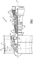
- FIG. 1 schematically illustrates a gas turbine engine 20.
- the gas turbine engine 20 is disclosed herein as a two-spool turbofan that generally incorporates a fan section 22, a compressor section 24, a combustor section 26 and a turbine section 28.
- the fan section 22 drives air along a bypass flow path B in a bypass duct defined within a nacelle 15, and also drives air along a core flow path C for compression and communication into the combustor section 26 then expansion through the turbine section 28.
- FIG. 1 schematically illustrates a gas turbine engine 20.
- the gas turbine engine 20 is disclosed herein as a two-spool turbofan that generally incorporates a fan section 22, a compressor section 24, a combustor section 26 and a turbine section 28.
- the fan section 22 drives air along a bypass flow path B in a bypass duct defined within a nacelle 15, and also drives air along a core flow path C for compression and communication into the combustor section 26 then expansion through the turbine section 28.
- FIG. 1 schematic
- the exemplary engine 20 generally includes a low speed spool 30 and a high speed spool 32 mounted for rotation about an engine central longitudinal axis A relative to an engine static structure 36 via several bearing systems 38. It should be understood that various bearing systems 38 at various locations may alternatively or additionally be provided, and the location of bearing systems 38 may be varied as appropriate to the application.
- the low speed spool 30 generally includes an inner shaft 40 that interconnects, a first (or low) pressure compressor 44 and a first (or low) pressure turbine 46.
- the inner shaft 40 is connected to the fan 42 through a speed change mechanism, which in exemplary gas turbine engine 20 is illustrated as a geared architecture 48 to drive a fan 42 at a lower speed than the low speed spool 30.
- the high speed spool 32 includes an outer shaft 50 that interconnects a second (or high) pressure compressor 52 and a second (or high) pressure turbine 54.
- a combustor 56 is arranged in exemplary gas turbine 20 between the high pressure compressor 52 and the high pressure turbine 54.
- a mid-turbine frame 57 of the engine static structure 36 may be arranged generally between the high pressure turbine 54 and the low pressure turbine 46.
- the mid-turbine frame 57 further supports bearing systems 38 in the turbine section 28.
- the inner shaft 40 and the outer shaft 50 are concentric and rotate via bearing systems 38 about the engine central longitudinal axis A which is colline
- the core airflow is compressed by the low pressure compressor 44 then the high pressure compressor 52, mixed and burned with fuel in the combustor 56, then expanded over the high pressure turbine 54 and low pressure turbine 46.
- the mid-turbine frame 57 includes airfoils 59 which are in the core airflow path C.
- the turbines 46, 54 rotationally drive the respective low speed spool 30 and high speed spool 32 in response to the expansion.
- gear system 48 may be located aft of the low pressure compressor, or aft of the combustor section 26 or even aft of turbine section 28, and fan 42 may be positioned forward or aft of the location of gear system 48.
- the engine 20 in one example is a high-bypass geared aircraft engine.
- the engine 20 bypass ratio is greater than about six (6), with an example embodiment being greater than about ten (10)
- the geared architecture 48 is an epicyclic gear train, such as a planetary gear system or other gear system, with a gear reduction ratio of greater than about 2.3 and the low pressure turbine 46 has a pressure ratio that is greater than about five.
- the engine 20 bypass ratio is greater than about ten (10:1)
- the fan diameter is significantly larger than that of the low pressure compressor 44
- the low pressure turbine 46 has a pressure ratio that is greater than about five (5:1).
- Low pressure turbine 46 pressure ratio is pressure measured prior to inlet of low pressure turbine 46 as related to the pressure at the outlet of the low pressure turbine 46 prior to an exhaust nozzle.
- the geared architecture 48 may be an epicycle gear train, such as a planetary gear system or other gear system, with a gear reduction ratio of greater than about 2.3:1 and less than about 5:1. It should be understood, however, that the above parameters are only exemplary of one embodiment of a geared architecture engine and that the present invention is applicable to other gas turbine engines including direct drive turbofans.
- the fan section 22 of the engine 20 is designed for a particular flight condition -- typically cruise at about 0.8 Mach and about 35,000 feet (10,668 meters).
- the flight condition of 0.8 Mach and 35,000 ft (10,668 meters), with the engine at its best fuel consumption - also known as "bucket cruise Thrust Specific Fuel Consumption ('TSFC')" - is the industry standard parameter of lbm of fuel being burned divided by lbf of thrust the engine produces at that minimum point.
- "Low fan pressure ratio” is the pressure ratio across the fan blade alone, without a Fan Exit Guide Vane (“FEGV”) system.
- the low fan pressure ratio as disclosed herein according to one non-limiting embodiment is less than about 1.45.
- Low corrected fan tip speed is the actual fan tip speed in ft/sec divided by an industry standard temperature correction of [(Tram °R) / (518.7 °R)] 0.5 .
- the "Low corrected fan tip speed” as disclosed herein according to one non-limiting embodiment is less than about 1150 ft / second (350.5 meters/second).
- FIG. 2 schematically illustrates a portion 100 of the turbine section 28.
- the portion 100 includes a first and second turbine blade 110. Radially outward of each turbine blade 110 is a corresponding blade outer air seal (BOAS) 120. Due to their exposure to the hot gasses in the core flow path C, each of the BOAS 120 and the blades 110 are referred to as gaspath components.
- Each of the blades 110 extends radially outward and into the flow path C from a corresponding platform 112.
- Disposed between the blades 110 is a vane 130.
- the vane 130 spans the flow path C from a radially outward platform 132 to a radially inner platform 134.
- one or more of the blades 110, BOAS 120, vane 130, and platforms 112, 132, 134 include internal cooling passages that receive a cooling fluid from another engine system. The cooling fluid is passed through the internal passages, thereby cooling the gaspath component.
- cooling air provided to the gaspath component can be received from a compressor bleed, a cooled cooling air system, or any other source of cooling fluid.
- the cooling fluid is received via a cool air port 140 positioned at a radially outward edge of the portion 100.
- the cooling fluid can be received from any number of known alternative cooling fluid sources instead of, or in addition to, the cool air port 140 and operate in a similar manner.
- FIGS 3A and 3B schematically illustrate exemplary internal cooling passages of a blade 110 ( Figure 3A ) and a vane 130 ( Figure 3B ). Included within each gaspath component are multiple internal cooling passages 210. Each internal cooling passage 210 is defined by a set of walls 212 and includes multiple turbulating features disposed on at least one of the walls 212. The exemplary turbulating features are trip strips 214 that protrude into the flowpath defined by the internal cooling passage. Each of the trip stripes 214 protrudes oblique to the wall.
- Trip strips incorporated into existing gaspath components are typically either linear in nature, or include a chevron (v) shape.
- Linear trip strips have a high heat transfer ability at the upstream most portion of the trip strip, with the heat transfer capabilities of the trip strip declining as the trip strip proceeds downstream.
- the trip strips can undergo extensive heat transfer decay and be ineffective at at least one downstream position.
- chevron shaped trip strips include an upstream most point from which two linear trip strip segments extend at a skewed orientation relative to the streamwise direction of the cooling flow.
- chevron configuration reduces the decay in convective heat transfer typically observed due to the thickening of the thermal boundary layer that occurs along the length of the trip surface, as the turbulence intensity of the local flow vortices are reduced resulting in lower heat transfer augmentation.
- Chevron trip strips typically exhibit the highest level of internal convective heat transfer at the apex formed by the intersection of each of the skewed trip strip segments.
- the location of the apex of the chevron trip configuration is typically more centrally located within the internal passage rather than at one of the edges, since it is desirable for both skewed segments of the chevron trip strip configuration to be of equivalent length. Having both skewed segments of the chevron trip strip minimizes the degradation in internal convective heat transfer that occurs with increasing trip strip segment lengths.
- the gaspath components illustrated herein include z-shaped trip strips 214.
- Each of the z-shaped trip strips includes two locally upstream most portions 211, 213, and two locally downstream most portions 215, 217.
- locally upstream most refers to a position where there is not an adjacent portion of the trip strip that is upstream of the position.
- locally downstream most refers to a position where there is not an adjacent portion of the trip strip that is downstream of the position.
- the upstream position is typically the first location in which the internal cooling flow immediately adjacent to the rib roughened wall initially contacts the turbulating feature (trip strip) and is coincident with the highest convective heat transfer location.
- the downstream position is typically the furthest location in which the internal cooling flow is in contact and/or comes in contact with the turbulating feature and is the location which has the lowest level of internal convective heat transfer augmentation.
- each of the blade 110, and the vane 130 it is appreciated that greater cooling is required at or near the exterior edges of at least some of the internal cooling passages 210.
- one of the locally upstream positions 211, 213 of each z-shaped trip strip 214 is positioned at the leading edge (LE).
- one of the locally upstream most positions 211, 213 of each z-shaped trip strip is positioned at the trailing edge.
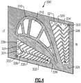
- Figure 4 schematically illustrates an exemplary platform 300, such as the blade platforms 112, or the vane platforms 132, 134 of Figure 2 .
- the blade or vane 310 Extending outward from the platform 300 is the blade or vane 310, which can include the internal flowpath passages 312, as discussed with regards to Figure 3A and Figure 3B .
- the exemplary platform 300 includes a first internal cooling passage 320 along the trailing edge TE and a second internal cooling passage 330 along a side edge 332.
- Each of the internal cooling passages 320, 330 is tapered, such that the passage is wider at an upstream end 324, 334, relative to cooling flow through the passage 320, 330 and narrower at a downstream end 326, 336.
- each the z-shaped trip strips 338 include at least one discontinuity 339. The inclusion of the discontinuity 339 decreases a pressure loss of the cooling fluid as the cooling fluid passes through the internal cooling passage 330.
- the discontinuity 339 occurs at one of the locally downstream most positions of each z-shaped trip strip 338, however it is understood that depending on the particular needs of a given trip strip 338, or internal cooling passage 320, 330, the discontinuity 339 may be incorporated at one of the locally upstream most positions 331 instead.
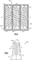
- FIG. 5 schematically illustrates a cross section of the blade outer air seal (BOAS) 120 of Figure 2 along cross section line A-A.
- the exemplary BOAS 120 includes three internal cooling passages 410, 420, 430, each of which includes multiple z-shaped trip strips 412, 422, 432.
- each of the z-shaped trip strips 412, in the internal cooling passage 410 adjacent the leading edge LE includes a local upstream most position 411 at the leading edge wall 450.
- each of the z-shaped trip strips 432 in the internal cooling passage 430 adjacent the trailing edge TE includes a locally upstream most position 431 contacting the trailing edge wall 452.
- a z-shaped configuration for the trip strips refers to a trip strip configuration where the trip strip includes at least two locally upstream most positions, and at least two locally downstream most positions. While a portion of these positions are illustrated as being ninety degree angled corners, it should be understood that alternate angles, and/or gradual bends can be utilized in place of the illustrated corners without requiring substantial modification to the described system.
- discontinuity can be positioned at any locally upstream most or locally downstream most position, and examples are envisioned including two or more additional discontinuities.
- Figure 6 schematically illustrates an example turbine blade 500 including two internal cooling passages 510. Disposed on at least one wall of the internal cooling passages 510 are multiple z-shaped trip strips 514. Each of the z-shaped trip strips 514 includes two discontinuities 530. The exemplary discontinuities are each disposed at a locally upstream or locally downstream most position on the trip strips. The length between the z-shaped discontinuities 530 is dictated by the internal cooling passage geometry width and desired local and average internal convective heat transfer requirements. In some instances the number of z-shaped trip strips 530 between any upstream and downstream location may vary in distance.
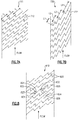
- Figures 7A and 7B illustrate highly schematic internal cooling passages 710, 720, as could be incorporated in any of the structures of Figures 1-6 .
- the z-shaped trip strips in the example of Figure 7A are characterized as having a uniform segment length L.
- the z-shaped trip strips 722 in the example of Figure 7B are characterized by having varied segment lengths L1, L2, L3, L4.
- the length of the segments of the z-shaped trip strips 712, 722 that exists between consecutive z-shaped features may be relatively short and range from (2.5 ⁇ L/H ⁇ 5) where L is the length of the segment of the z-shaped trip strip 530 and H is the height of the z-shaped trip strip 530.
- the relative distance between consecutive z-shaped trip strips 530 may comprise of either equidistant and/or varying distances depending on local convective thermal cooling requirements and pressure loss considerations.
- Figure 8 illustrates a highly schematic internal cooling passage 810 including multiple z-shaped trip strips 820.
- the z-shaped trip strips 820 of the example of Figure 8 include multiple variable angle z-shaped trip strips 820.
- Each of the z-shaped trip strips defines a corner angle 822, 824, 826, 828 at each of the locally downstream most positions 832 and locally upstream most positions 834 of the z-shaped trip strips 820.
- the angles 822, 824, 826, 828 can vary from corner to corner within a single z-shaped trip strip 820.
- the angles 822, 824, 826, 828 can be uniform within each z-shaped trip strip 820, but vary from z-shaped trip strip to z-shaped trip strip within the same passage 810.
- the angles 822, 824, 826, 828 in a given z-shaped trip strip can be constant at each of the locally downstream most positions 832, constant at each of the locally upstream most positions 834, but the angle at the locally downstream most positions 832 is distinct from the angle at the corresponding locally upstream most positions 834.
Landscapes
- Engineering & Computer Science (AREA)
- Mechanical Engineering (AREA)
- General Engineering & Computer Science (AREA)
- Chemical & Material Sciences (AREA)
- Combustion & Propulsion (AREA)
- Turbine Rotor Nozzle Sealing (AREA)
Abstract
Description
- The present disclosure relates generally to gaspath component cooling systems, and more specifically to a z-shaped trip strip configuration for the same.
- Gas turbine engines, such as those utilized in commercial and military aircraft, include a compressor section that compresses air, a combustor section in which the compressed air is mixed with a fuel and ignited, and a turbine section across which the resultant combustion products are expanded. The expansion of the combustion products drives the turbine section to rotate. As the turbine section is connected to the compressor section via a shaft, the rotation of the turbine section further drives the compressor section to rotate. In some examples, a fan is also connected to the shaft and is driven to rotate via rotation of the turbine as well.
- Gas turbine engines include multiple gaspaths defining flow from an ingestion point at a fore end of the engine to an exhaustion point at an aft end of the engine. Due to operation of the gas turbine engine, components exposed to, or spanning, the gaspaths are subjected to high levels of heat. In order to mitigate potential damage to the components from the exposure to the heat, some gaspath components are actively cooled by passing a coolant through cooling passages internal to the gaspath component.
- In a first exemplary embodiment of this disclosure, a gaspath component for a gas turbine engine includes a platform including at least one internal cooling passage, and the at least one internal cooling passage having a plurality of trip strips extending into the cooling passage from at least one internal surface of the cooling passage, each of the trip strips being defined by a z-shaped configuration.
- In an example of the above described gaspath component for a gas turbine engine the platform is one of a blade outer air seal a combustor panel, a vane platform, and a blade platform.
- In another example of either of the above described gaspath components for a gas turbine engine the z-shaped configuration is continuous.
- In another example of any of the above described gaspath components for a gas turbine engine the z-shaped configuration includes at least one discontinuity.
- In another example of any of the above described gaspath components for a gas turbine engine the at least one discontinuity is positioned at one of a locally upstream most position and a locally downstream most position of the trip strip.
- In another example of any of the above described gaspath components for a gas turbine engine the at least one internal cooling passage includes a first internal cooling passage and a second internal cooling passage, and wherein the first internal cooling passage is adjacent a first platform edge.
- In another example of any of the above described gaspath components for a gas turbine engine a locally upstream most portion of each trip strip within the first internal cooling passage contacts a wall adjacent to the first platform edge.
- In another example of any of the above described gaspath components for a gas turbine engine the second internal cooling passage is adjacent to a second platform edge, and wherein a locally upstream most portion of each trip strip within the second internal cooling passage contacts a wall adjacent to the second platform edge.
- In another example of any of the above described gaspath components for a gas turbine engine an orientation of each trip strip in the first internal cooling passage is inverted relative to an orientation of each trip strip in the second internal cooling passage.
- In another example of any of the above described gaspath components for a gas turbine engine each of the trip strips includes a plurality of z-shaped configurations, each of the z-shaped configurations being defined by a first segment, a second segment and a third segment and wherein at least one of the first segment and the third segment of a given z-shaped configuration is the other of the first segment and the third segment of an adjacent z-shaped configuration.
- In another example of any of the above described gaspath components for a gas turbine engine each of the first segments and each of the third segments has the same length.
- In another example of any of the above described gaspath components for a gas turbine engine at least one of the first segments and the third segments has a distinct length from at least one other of the first segments and the third segments.
- In another example of any of the above described gaspath components for a gas turbine engine an angle defined by the trip strip at a locally upstream most position is distinct from an angle defined by the trip strip at a corresponding locally downstream most position.
- In another example of any of the above described gaspath components for a gas turbine engine each angle defined by a locally upstream most position of the z-shaped trip strip is identical.
- In another example of any of the above described gaspath components for a gas turbine engine at least one angle defined by a locally upstream most position of the z-shaped trip strip is distinct form at an angle defined by at least one other locally upstream most position of the z-shaped trip strip.
- In a second exemplary embodiment of this disclosure, a gaspath component for a gas turbine engine includes an airfoil shaped component including at least one internal cooling passage, and the at least one internal cooling passage having a plurality of trip strips extending into the cooling passage from at least one internal surface of the cooling passage, each of the trip strips being defined by a discontinuous z-shaped configuration.
- Although this second exemplary embodiment is not explicitly claimed in the present application, the applicant reserves the right to claim this embodiment, and any of the dependent example features recited below and associated therewith in a divisional application.
- In an example of the above described gaspath component for a gas turbine engine the airfoil shaped component is one of a blade and a vane.
- In another example of either of the above described gaspath components for a gas turbine engine the at least one internal cooling passage includes a first internal cooling passage and a second internal cooling passage, and wherein the first internal cooling passage is adjacent a leading edge of the airfoil shaped component.
- In another example of any of the above described gaspath components for a gas turbine engine a locally upstream most portion of each trip strip within the first internal cooling passage contacts a leading edge wall.
- In another example of any of the above described gaspath components for a gas turbine engine the second internal cooling passage is adjacent to a trailing edge of the airfoil shaped component, and wherein a locally upstream most portion of each trip strip within the second internal cooling passage is adjacent to the trailing edge of the airfoil shaped component.
- In another example of any of the above described gaspath components for a gas turbine engine an orientation of each trip strip in the first internal cooling passage is inverted relative to an orientation of each trip strip in the second internal cooling passage.
- In another example of any of the above described gaspath components for a gas turbine engine at least one discontinuity of the discontinuous z-shaped configuration is positioned at one of a locally upstream most position and a locally downstream most position of the trip strip.
- In another example of any of the above described gaspath components for a gas turbine engine a first upstream most position and a second upstream most position of each trip strip in the plurality of trip strips is at a same position, relative to an expected flow of fluid through the internal cooling passage.
- In another example of any of the above described gaspath components for a gas turbine engine further includes a platform from which the airfoil shaped component extends, and wherein the platform includes at least one internal platform cooling passage having a plurality of z-shaped trip strips.
- In another example of any of the above described gaspath components for a gas turbine engine each trip strip in the internal platform cooling passage is discontinuous
- These and other features of the present invention can be best understood from the following specification and drawings, the following of which is a brief description.
-
-
Figure 1 schematically illustrates an exemplary gas turbine engine. -
Figure 2 schematically illustrates a portion of the turbine section of the gas turbine engine ofFigure 1 . -
Figures 3A and 3B schematically illustrate an exemplary turbine blade (Figure 3A ) and turbine vane (Figure 3B ) incorporating z-shaped trip strips within internal cooling passages. -
Figure 4 schematically illustrates an exemplary vane or blade platform incorporating z-shaped trip strips within internal cooling passages. -
Figure 5 schematically illustrates a cross section of a blade outer air seal platform incorporating z-shaped trip strips within internal cooling passages. -
Figure 6 schematically illustrates an exemplary turbine blade incorporating z-shaped trip strips within internal cooling passages. -
Figures 7A and 7B illustrate highly schematic internal cooling passages as could be incorporated in any of the structures ofFigures 1-6 . -
Figure 8 schematically illustrates a highly schematic internal cooling passage as could be incorporated in any of the structures ofFigures 1-6 . -
Figure 1 schematically illustrates agas turbine engine 20. Thegas turbine engine 20 is disclosed herein as a two-spool turbofan that generally incorporates afan section 22, acompressor section 24, acombustor section 26 and aturbine section 28. Thefan section 22 drives air along a bypass flow path B in a bypass duct defined within anacelle 15, and also drives air along a core flow path C for compression and communication into thecombustor section 26 then expansion through theturbine section 28. Although depicted as a two-spool turbofan gas turbine engine in the disclosed non-limiting embodiment, it should be understood that the concepts described herein are not limited to use with two-spool turbofans as the teachings may be applied to other types of turbine engines including three-spool architectures. - The
exemplary engine 20 generally includes alow speed spool 30 and ahigh speed spool 32 mounted for rotation about an engine central longitudinal axis A relative to an enginestatic structure 36 viaseveral bearing systems 38. It should be understood thatvarious bearing systems 38 at various locations may alternatively or additionally be provided, and the location ofbearing systems 38 may be varied as appropriate to the application. - The
low speed spool 30 generally includes aninner shaft 40 that interconnects, a first (or low)pressure compressor 44 and a first (or low)pressure turbine 46. Theinner shaft 40 is connected to thefan 42 through a speed change mechanism, which in exemplarygas turbine engine 20 is illustrated as a gearedarchitecture 48 to drive afan 42 at a lower speed than thelow speed spool 30. Thehigh speed spool 32 includes anouter shaft 50 that interconnects a second (or high)pressure compressor 52 and a second (or high)pressure turbine 54. Acombustor 56 is arranged inexemplary gas turbine 20 between thehigh pressure compressor 52 and thehigh pressure turbine 54. Amid-turbine frame 57 of the enginestatic structure 36 may be arranged generally between thehigh pressure turbine 54 and thelow pressure turbine 46. Themid-turbine frame 57 further supports bearingsystems 38 in theturbine section 28. Theinner shaft 40 and theouter shaft 50 are concentric and rotate viabearing systems 38 about the engine central longitudinal axis A which is collinear with their longitudinal axes. - The core airflow is compressed by the
low pressure compressor 44 then thehigh pressure compressor 52, mixed and burned with fuel in thecombustor 56, then expanded over thehigh pressure turbine 54 andlow pressure turbine 46. Themid-turbine frame 57 includesairfoils 59 which are in the core airflow path C. Theturbines low speed spool 30 andhigh speed spool 32 in response to the expansion. It will be appreciated that each of the positions of thefan section 22,compressor section 24,combustor section 26,turbine section 28, and fandrive gear system 48 may be varied. For example,gear system 48 may be located aft of the low pressure compressor, or aft of thecombustor section 26 or even aft ofturbine section 28, andfan 42 may be positioned forward or aft of the location ofgear system 48. - The
engine 20 in one example is a high-bypass geared aircraft engine. In a further example, theengine 20 bypass ratio is greater than about six (6), with an example embodiment being greater than about ten (10), the gearedarchitecture 48 is an epicyclic gear train, such as a planetary gear system or other gear system, with a gear reduction ratio of greater than about 2.3 and thelow pressure turbine 46 has a pressure ratio that is greater than about five. In one disclosed embodiment, theengine 20 bypass ratio is greater than about ten (10:1), the fan diameter is significantly larger than that of thelow pressure compressor 44, and thelow pressure turbine 46 has a pressure ratio that is greater than about five (5:1).Low pressure turbine 46 pressure ratio is pressure measured prior to inlet oflow pressure turbine 46 as related to the pressure at the outlet of thelow pressure turbine 46 prior to an exhaust nozzle. The gearedarchitecture 48 may be an epicycle gear train, such as a planetary gear system or other gear system, with a gear reduction ratio of greater than about 2.3:1 and less than about 5:1. It should be understood, however, that the above parameters are only exemplary of one embodiment of a geared architecture engine and that the present invention is applicable to other gas turbine engines including direct drive turbofans. - A significant amount of thrust is provided by the bypass flow B due to the high bypass ratio. The
fan section 22 of theengine 20 is designed for a particular flight condition -- typically cruise at about 0.8 Mach and about 35,000 feet (10,668 meters). The flight condition of 0.8 Mach and 35,000 ft (10,668 meters), with the engine at its best fuel consumption - also known as "bucket cruise Thrust Specific Fuel Consumption ('TSFC')" - is the industry standard parameter of lbm of fuel being burned divided by lbf of thrust the engine produces at that minimum point. "Low fan pressure ratio" is the pressure ratio across the fan blade alone, without a Fan Exit Guide Vane ("FEGV") system. The low fan pressure ratio as disclosed herein according to one non-limiting embodiment is less than about 1.45. "Low corrected fan tip speed" is the actual fan tip speed in ft/sec divided by an industry standard temperature correction of [(Tram °R) / (518.7 °R)]0.5. The "Low corrected fan tip speed" as disclosed herein according to one non-limiting embodiment is less than about 1150 ft / second (350.5 meters/second). - With continued reference to
Figure 1 ,Figure 2 schematically illustrates aportion 100 of theturbine section 28. Theportion 100 includes a first andsecond turbine blade 110. Radially outward of eachturbine blade 110 is a corresponding blade outer air seal (BOAS) 120. Due to their exposure to the hot gasses in the core flow path C, each of theBOAS 120 and theblades 110 are referred to as gaspath components. Each of theblades 110 extends radially outward and into the flow path C from acorresponding platform 112. Disposed between theblades 110 is avane 130. Thevane 130 spans the flow path C from a radiallyoutward platform 132 to a radiallyinner platform 134. - Due to the position downstream of the combustor, the
turbine section 28 is exposed to substantial amounts of heat during operation of the engine. The substantial heat can reduce the lifespan of, or otherwise degrade, one or more of the gaspath components. In order to minimize the negative impact of the exposure, one or more of theblades 110,BOAS 120,vane 130, andplatforms Figure 2 , the cooling fluid is received via a cool air port 140 positioned at a radially outward edge of theportion 100. In alternative examples, the cooling fluid can be received from any number of known alternative cooling fluid sources instead of, or in addition to, the cool air port 140 and operate in a similar manner. - With continued reference to
Figure 2 , and with like numerals indicating like elements,Figures 3A and 3B schematically illustrate exemplary internal cooling passages of a blade 110 (Figure 3A ) and a vane 130 (Figure 3B ). Included within each gaspath component are multipleinternal cooling passages 210. Eachinternal cooling passage 210 is defined by a set ofwalls 212 and includes multiple turbulating features disposed on at least one of thewalls 212. The exemplary turbulating features aretrip strips 214 that protrude into the flowpath defined by the internal cooling passage. Each of thetrip stripes 214 protrudes oblique to the wall. - Trip strips incorporated into existing gaspath components are typically either linear in nature, or include a chevron (v) shape. Linear trip strips have a high heat transfer ability at the upstream most portion of the trip strip, with the heat transfer capabilities of the trip strip declining as the trip strip proceeds downstream. As a result, any time the internal cavity is above a certain width dimension, the trip strips can undergo extensive heat transfer decay and be ineffective at at least one downstream position. Similarly, chevron shaped trip strips include an upstream most point from which two linear trip strip segments extend at a skewed orientation relative to the streamwise direction of the cooling flow. Due to the relatively reduced lengths of each of the trip strip segments the chevron configuration reduces the decay in convective heat transfer typically observed due to the thickening of the thermal boundary layer that occurs along the length of the trip surface, as the turbulence intensity of the local flow vortices are reduced resulting in lower heat transfer augmentation. Chevron trip strips typically exhibit the highest level of internal convective heat transfer at the apex formed by the intersection of each of the skewed trip strip segments. The location of the apex of the chevron trip configuration is typically more centrally located within the internal passage rather than at one of the edges, since it is desirable for both skewed segments of the chevron trip strip configuration to be of equivalent length. Having both skewed segments of the chevron trip strip minimizes the degradation in internal convective heat transfer that occurs with increasing trip strip segment lengths.
- In order to gain some of the advantages of both the linear trip strips and the chevron trip strips, while mitigating the resulting downsides, the gaspath components illustrated herein include z-shaped trip strips 214. Each of the z-shaped trip strips includes two locally upstream
most portions most portions - The upstream position is typically the first location in which the internal cooling flow immediately adjacent to the rib roughened wall initially contacts the turbulating feature (trip strip) and is coincident with the highest convective heat transfer location. Conversely the downstream position is typically the furthest location in which the internal cooling flow is in contact and/or comes in contact with the turbulating feature and is the location which has the lowest level of internal convective heat transfer augmentation.
- Further, in each of the
blade 110, and thevane 130, it is appreciated that greater cooling is required at or near the exterior edges of at least some of theinternal cooling passages 210. In order to meet this greater cooling requirement, in theinternal cooling passage 210 adjacent the leading edge (LE) one of the locallyupstream positions trip strip 214 is positioned at the leading edge (LE). Similarly, in theinternal cooling passage 210 adjacent the trailing edge TE, one of the locally upstreammost positions - In examples such as the blade 110 (
Figure 3A ), where fluid is passing through bothinternal cooling passages 210 in the same direction, the z-shaped trip strips 214 in theinternal cooling passages 210 adjacent to the trailing edge TE are inverted, relative to those in theinternal cooling passage 210 adjacent to the leading edge LE. In contrast, gaspath components where theinternal cooling passages 210 include reversed flow directions between theinternal cooling passages 210, such as the vane 130 (Figure 3B ), result in substantially identical z-shaped trip strips 214 in each of theinternal cooling passages 210. - With continued reference to
Figures 2 ,3A and3B ,Figure 4 schematically illustrates anexemplary platform 300, such as theblade platforms 112, or thevane platforms Figure 2 . Extending outward from theplatform 300 is the blade orvane 310, which can include the internalflowpath passages 312, as discussed with regards toFigure 3A and Figure 3B . Theexemplary platform 300 includes a firstinternal cooling passage 320 along the trailing edge TE and a secondinternal cooling passage 330 along aside edge 332. Each of theinternal cooling passages upstream end passage downstream end - Due to the tapered nature of the
internal cooling passages most positions internal cooling passage discontinuity 339. The inclusion of thediscontinuity 339 decreases a pressure loss of the cooling fluid as the cooling fluid passes through theinternal cooling passage 330. In the illustrated example, thediscontinuity 339 occurs at one of the locally downstream most positions of each z-shapedtrip strip 338, however it is understood that depending on the particular needs of a giventrip strip 338, orinternal cooling passage discontinuity 339 may be incorporated at one of the locally upstreammost positions 331 instead. - With continued reference to
Figures 2-4 ,Figure 5 schematically illustrates a cross section of the blade outer air seal (BOAS) 120 ofFigure 2 along cross section line A-A. Theexemplary BOAS 120 includes threeinternal cooling passages internal cooling passage 410 adjacent the leading edge LE includes a local upstreammost position 411 at theleading edge wall 450. Similarly, each of the z-shaped trip strips 432 in theinternal cooling passage 430 adjacent the trailing edge TE includes a locally upstreammost position 431 contacting the trailingedge wall 452. - With regards to all Figures, and the description contained herein, reference to a z-shaped configuration for the trip strips refers to a trip strip configuration where the trip strip includes at least two locally upstream most positions, and at least two locally downstream most positions. While a portion of these positions are illustrated as being ninety degree angled corners, it should be understood that alternate angles, and/or gradual bends can be utilized in place of the illustrated corners without requiring substantial modification to the described system.
- Further, while specific examples are illustrated including a single discontinuity within the z-shaped trip strip at the locally upstream most position, it should be appreciated that the discontinuity can be positioned at any locally upstream most or locally downstream most position, and examples are envisioned including two or more additional discontinuities.
- With continued reference to
Figures 1-5 ,Figure 6 schematically illustrates anexample turbine blade 500 including twointernal cooling passages 510. Disposed on at least one wall of theinternal cooling passages 510 are multiple z-shaped trip strips 514. Each of the z-shaped trip strips 514 includes twodiscontinuities 530. The exemplary discontinuities are each disposed at a locally upstream or locally downstream most position on the trip strips. The length between the z-shapeddiscontinuities 530 is dictated by the internal cooling passage geometry width and desired local and average internal convective heat transfer requirements. In some instances the number of z-shaped trip strips 530 between any upstream and downstream location may vary in distance. - With continued reference to
Figures 1-6 ,Figures 7A and 7B illustrate highly schematicinternal cooling passages Figures 1-6 . The z-shaped trip strips in the example ofFigure 7A are characterized as having a uniform segment length L. In contrast, the z-shaped trip strips 722 in the example ofFigure 7B are characterized by having varied segment lengths L1, L2, L3, L4. - The length of the segments of the z-shaped trip strips 712, 722 that exists between consecutive z-shaped features may be relatively short and range from (2.5 ≤ L/H ≤ 5) where L is the length of the segment of the z-shaped
trip strip 530 and H is the height of the z-shapedtrip strip 530. Similarly the relative distance between consecutive z-shaped trip strips 530 may comprise of either equidistant and/or varying distances depending on local convective thermal cooling requirements and pressure loss considerations. - With continued reference to
Figures 1-6 ,Figure 8 illustrates a highly schematicinternal cooling passage 810 including multiple z-shaped trip strips 820. The z-shaped trip strips 820 of the example ofFigure 8 include multiple variable angle z-shaped trip strips 820. Each of the z-shaped trip strips defines acorner angle most positions 832 and locally upstreammost positions 834 of the z-shaped trip strips 820. - As illustrated in the example of
Figure 8 , theangles trip strip 820. In alternative examples, theangles trip strip 820, but vary from z-shaped trip strip to z-shaped trip strip within thesame passage 810. In yet further examples, theangles most positions 832, constant at each of the locally upstreammost positions 834, but the angle at the locally downstreammost positions 832 is distinct from the angle at the corresponding locally upstream most positions 834. - It is further understood that any of the above described concepts can be used alone or in combination with any or all of the other above described concepts. Although an embodiment of this invention has been disclosed, a worker of ordinary skill in this art would recognize that certain modifications would come within the scope of this invention. For that reason, the following claims should be studied to determine the true scope and content of this invention.
Claims (15)
- A gaspath component for a gas turbine engine (20) comprising:a platform (112,120,132,134;300) including at least one internal cooling passage (320,330;410,420,430;710;720;810); andthe at least one internal cooling passage (320...810) having a plurality of trip strips (328,338;412,422,432;712,722;820) extending into the cooling passage (320...810) from at least one internal surface of the cooling passage (320...810), each of the trip strips (328...820) being defined by a z-shaped configuration.
- The gaspath component of claim 1, wherein the platform (112,120,132,134;300) is one of a blade outer air seal (120), a combustor panel, a vane platform (132,134), and a blade platform (112).
- The gaspath component of claim 1 or 2, wherein the z-shaped configuration is continuous.
- The gaspath component of claim 1 or 2, wherein the z-shaped configuration includes at least one discontinuity (339;530).
- The gaspath component of claim 4, wherein the at least one discontinuity (339;530) is positioned at one of a locally upstream most position and a locally downstream most position of the trip strip (338;422).
- The gaspath component of any preceding claim, wherein the at least one internal cooling passage (320...810) includes a first internal cooling passage (320;410) and a second internal cooling passage (330;420,430), and wherein the first internal cooling passage (320;410) is adjacent a first platform edge.
- The gaspath component of claim 6, wherein a locally upstream most portion of each trip strip (328;412) within the first internal cooling passage (320;410) contacts a wall adjacent to the first platform edge.
- The gaspath component of claim 6 or 7, wherein the second internal cooling passage (330;420,430) is adjacent to a second platform edge, and wherein a locally upstream most portion of each trip strip (338;422,432) within the second internal cooling passage (330;420,430) contacts a wall adjacent to the second platform edge.
- The gaspath component of claim 6, 7 or 8 wherein an orientation of each trip strip (412) in the first internal cooling passage (410) is inverted relative to an orientation of each trip strip (422) in the second internal cooling passage (420).
- The gaspath component of any preceding claim, wherein each of the trip strips (328...820) includes a plurality of z-shaped configurations, each of the z-shaped configurations being defined by a first segment, a second segment and a third segment and wherein at least one of the first segment and the third segment of a given z-shaped configuration is the other of the first segment and the third segment of an adjacent z-shaped configuration.
- The gaspath component of claim 10, wherein each of the first segments and each of the third segments has the same length.
- The gaspath component of claim 10, wherein at least one of the first segments and the third segments has a distinct length from at least one other of the first segments and the third segments.
- The gaspath component of any preceding claim, wherein an angle (824,828) defined by the trip strip (820) at a locally upstream most position (834) is distinct from an angle (822,826) defined by the trip strip (820) at a corresponding locally downstream most position (832).
- The gaspath component of any preceding claim, wherein each angle (824,828) defined by a locally upstream most position (834) of the z-shaped trip strip (820) is identical.
- The gaspath component of any of claims 1 to 13, wherein at least one angle (824,828) defined by a locally upstream most position (834) of the z-shaped trip strip (820) is distinct from an angle (824,828) defined by at least one other locally upstream most position (834) of the z-shaped trip strip (820).
Applications Claiming Priority (1)
| Application Number | Priority Date | Filing Date | Title |
|---|---|---|---|
| US16/010,776 US10808552B2 (en) | 2018-06-18 | 2018-06-18 | Trip strip configuration for gaspath component in a gas turbine engine |
Publications (2)
| Publication Number | Publication Date |
|---|---|
| EP3584408A1 true EP3584408A1 (en) | 2019-12-25 |
| EP3584408B1 EP3584408B1 (en) | 2021-09-01 |
Family
ID=66912591
Family Applications (1)
| Application Number | Title | Priority Date | Filing Date |
|---|---|---|---|
| EP19180393.1A Active EP3584408B1 (en) | 2018-06-18 | 2019-06-14 | Trip strip configuration for gaspath component in a gas turbine engine |
Country Status (2)
| Country | Link |
|---|---|
| US (1) | US10808552B2 (en) |
| EP (1) | EP3584408B1 (en) |
Families Citing this family (1)
| Publication number | Priority date | Publication date | Assignee | Title |
|---|---|---|---|---|
| US10808552B2 (en) * | 2018-06-18 | 2020-10-20 | Raytheon Technologies Corporation | Trip strip configuration for gaspath component in a gas turbine engine |
Citations (8)
| Publication number | Priority date | Publication date | Assignee | Title |
|---|---|---|---|---|
| DE19526917A1 (en) * | 1995-07-22 | 1997-01-23 | Fiebig Martin Prof Dr Ing | Longitudinal swirl generating roughening elements |
| US20060042255A1 (en) * | 2004-08-26 | 2006-03-02 | General Electric Company | Combustor cooling with angled segmented surfaces |
| EP1914390A2 (en) * | 2006-10-12 | 2008-04-23 | United Technologies Corporation | Blade outer air seals |
| EP2019187A2 (en) * | 2007-07-24 | 2009-01-28 | United Technologies Corporation | Apparatus and methods for providing vane platform cooling |
| WO2014052323A1 (en) * | 2012-09-28 | 2014-04-03 | United Technologies Corporation | Uber-cooled turbine section component made by additive manufacturing |
| US20140096527A1 (en) * | 2012-10-04 | 2014-04-10 | United Technologies Corporation | Gas turbine engine combustor liner |
| US20140219813A1 (en) * | 2012-09-14 | 2014-08-07 | Rafael A. Perez | Gas turbine engine serpentine cooling passage |
| US20160265775A1 (en) * | 2013-11-21 | 2016-09-15 | United Technologies Corporation | Turbine engine multi-walled structure with internal cooling element(s) |
Family Cites Families (28)
| Publication number | Priority date | Publication date | Assignee | Title |
|---|---|---|---|---|
| US3741285A (en) * | 1968-07-09 | 1973-06-26 | A Kuethe | Boundary layer control of flow separation and heat exchange |
| US4627480A (en) * | 1983-11-07 | 1986-12-09 | General Electric Company | Angled turbulence promoter |
| US5052889A (en) * | 1990-05-17 | 1991-10-01 | Pratt & Whintey Canada | Offset ribs for heat transfer surface |
| US5681144A (en) * | 1991-12-17 | 1997-10-28 | General Electric Company | Turbine blade having offset turbulators |
| US5413458A (en) * | 1994-03-29 | 1995-05-09 | United Technologies Corporation | Turbine vane with a platform cavity having a double feed for cooling fluid |
| US5797726A (en) * | 1997-01-03 | 1998-08-25 | General Electric Company | Turbulator configuration for cooling passages or rotor blade in a gas turbine engine |
| US7575414B2 (en) * | 2005-04-01 | 2009-08-18 | General Electric Company | Turbine nozzle with trailing edge convection and film cooling |
| US7544044B1 (en) * | 2006-08-11 | 2009-06-09 | Florida Turbine Technologies, Inc. | Turbine airfoil with pedestal and turbulators cooling |
| US7866947B2 (en) | 2007-01-03 | 2011-01-11 | United Technologies Corporation | Turbine blade trip strip orientation |
| US8057177B2 (en) * | 2008-01-10 | 2011-11-15 | General Electric Company | Turbine blade tip shroud |
| US8348612B2 (en) * | 2008-01-10 | 2013-01-08 | General Electric Company | Turbine blade tip shroud |
| US8128366B2 (en) * | 2008-06-06 | 2012-03-06 | United Technologies Corporation | Counter-vortex film cooling hole design |
| US8109726B2 (en) * | 2009-01-19 | 2012-02-07 | Siemens Energy, Inc. | Turbine blade with micro channel cooling system |
| US8317475B1 (en) | 2010-01-25 | 2012-11-27 | Florida Turbine Technologies, Inc. | Turbine airfoil with micro cooling channels |
| US8961133B2 (en) * | 2010-12-28 | 2015-02-24 | Rolls-Royce North American Technologies, Inc. | Gas turbine engine and cooled airfoil |
| EP2685048B1 (en) * | 2011-03-11 | 2016-02-10 | Mitsubishi Hitachi Power Systems, Ltd. | Gas turbine rotor blade, and gas turbine |
| US9476308B2 (en) * | 2012-12-27 | 2016-10-25 | United Technologies Corporation | Gas turbine engine serpentine cooling passage with chevrons |
| EP2954168B1 (en) * | 2013-02-05 | 2019-07-03 | United Technologies Corporation | Gas turbine engine component having curved turbulator |
| US8939706B1 (en) * | 2014-02-25 | 2015-01-27 | Siemens Energy, Inc. | Turbine abradable layer with progressive wear zone having a frangible or pixelated nib surface |
| US9151175B2 (en) * | 2014-02-25 | 2015-10-06 | Siemens Aktiengesellschaft | Turbine abradable layer with progressive wear zone multi level ridge arrays |
| US10774655B2 (en) * | 2014-04-04 | 2020-09-15 | Raytheon Technologies Corporation | Gas turbine engine component with flow separating rib |
| CA2950011C (en) * | 2014-05-29 | 2020-01-28 | General Electric Company | Fastback turbulator |
| US10392942B2 (en) * | 2014-11-26 | 2019-08-27 | Ansaldo Energia Ip Uk Limited | Tapered cooling channel for airfoil |
| US9777635B2 (en) * | 2014-12-31 | 2017-10-03 | General Electric Company | Engine component |
| US9850763B2 (en) * | 2015-07-29 | 2017-12-26 | General Electric Company | Article, airfoil component and method for forming article |
| US11085304B2 (en) * | 2018-06-07 | 2021-08-10 | Raytheon Technologies Corporation | Variably skewed trip strips in internally cooled components |
| US10808552B2 (en) * | 2018-06-18 | 2020-10-20 | Raytheon Technologies Corporation | Trip strip configuration for gaspath component in a gas turbine engine |
| US10815793B2 (en) * | 2018-06-19 | 2020-10-27 | Raytheon Technologies Corporation | Trip strips for augmented boundary layer mixing |
-
2018
- 2018-06-18 US US16/010,776 patent/US10808552B2/en active Active
-
2019
- 2019-06-14 EP EP19180393.1A patent/EP3584408B1/en active Active
Patent Citations (8)
| Publication number | Priority date | Publication date | Assignee | Title |
|---|---|---|---|---|
| DE19526917A1 (en) * | 1995-07-22 | 1997-01-23 | Fiebig Martin Prof Dr Ing | Longitudinal swirl generating roughening elements |
| US20060042255A1 (en) * | 2004-08-26 | 2006-03-02 | General Electric Company | Combustor cooling with angled segmented surfaces |
| EP1914390A2 (en) * | 2006-10-12 | 2008-04-23 | United Technologies Corporation | Blade outer air seals |
| EP2019187A2 (en) * | 2007-07-24 | 2009-01-28 | United Technologies Corporation | Apparatus and methods for providing vane platform cooling |
| US20140219813A1 (en) * | 2012-09-14 | 2014-08-07 | Rafael A. Perez | Gas turbine engine serpentine cooling passage |
| WO2014052323A1 (en) * | 2012-09-28 | 2014-04-03 | United Technologies Corporation | Uber-cooled turbine section component made by additive manufacturing |
| US20140096527A1 (en) * | 2012-10-04 | 2014-04-10 | United Technologies Corporation | Gas turbine engine combustor liner |
| US20160265775A1 (en) * | 2013-11-21 | 2016-09-15 | United Technologies Corporation | Turbine engine multi-walled structure with internal cooling element(s) |
Also Published As
| Publication number | Publication date |
|---|---|
| US10808552B2 (en) | 2020-10-20 |
| US20190383149A1 (en) | 2019-12-19 |
| EP3584408B1 (en) | 2021-09-01 |
Similar Documents
| Publication | Publication Date | Title |
|---|---|---|
| US11148191B2 (en) | Core arrangement for turbine engine component | |
| US20220003120A1 (en) | Airfoil tip pocket with augmentation features | |
| US10253635B2 (en) | Blade tip cooling arrangement | |
| US11781439B2 (en) | Seal arrangement for turbine engine component | |
| US10830070B2 (en) | Endwall countouring trench | |
| EP3342982B1 (en) | Inclined crossover passages for internal airfoil cavities | |
| EP2956646B1 (en) | Component for a gas turbine engine and corresponding method of forming a cooling hole | |
| EP3296519B1 (en) | Flowpath component for a gas turbine engine including a chordal seal | |
| EP3444436A1 (en) | Directional cooling arrangement for turbine airfoils | |
| EP3550108B1 (en) | Endwall contour | |
| EP3477056B1 (en) | Gas turbine engine airfoil array | |
| EP2960433B1 (en) | Gas turbine engine airfoil comprising angled cooling passages in the leading edge | |
| US10151210B2 (en) | Endwall contouring for airfoil rows with varying airfoil geometries | |
| EP3179040B1 (en) | Component for a gas turbine engine and corresponding a method of manufacturing a film-cooled article | |
| EP3112596A1 (en) | Gas turbine engine airfoil with bi-axial skin cooling passage and corresponding gas turbine engine | |
| EP3009600A1 (en) | Gas turbine engine turbine blade with cooled tip | |
| US10215031B2 (en) | Gas turbine engine component cooling with interleaved facing trip strips | |
| EP3045666B1 (en) | Airfoil platform with cooling feed orifices | |
| EP3584408B1 (en) | Trip strip configuration for gaspath component in a gas turbine engine | |
| EP3584409B1 (en) | Turbine airfoil with minicore passage having sloped diffuser orifice | |
| EP3907373B1 (en) | Turbine blade cooling hole combination |
Legal Events
| Date | Code | Title | Description |
|---|---|---|---|
| PUAI | Public reference made under article 153(3) epc to a published international application that has entered the european phase |
Free format text: ORIGINAL CODE: 0009012 |
|
| STAA | Information on the status of an ep patent application or granted ep patent |
Free format text: STATUS: THE APPLICATION HAS BEEN PUBLISHED |
|
| AK | Designated contracting states |
Kind code of ref document: A1 Designated state(s): AL AT BE BG CH CY CZ DE DK EE ES FI FR GB GR HR HU IE IS IT LI LT LU LV MC MK MT NL NO PL PT RO RS SE SI SK SM TR |
|
| AX | Request for extension of the european patent |
Extension state: BA ME |
|
| STAA | Information on the status of an ep patent application or granted ep patent |
Free format text: STATUS: REQUEST FOR EXAMINATION WAS MADE |
|
| 17P | Request for examination filed |
Effective date: 20200622 |
|
| RBV | Designated contracting states (corrected) |
Designated state(s): AL AT BE BG CH CY CZ DE DK EE ES FI FR GB GR HR HU IE IS IT LI LT LU LV MC MK MT NL NO PL PT RO RS SE SI SK SM TR |
|
| RAP1 | Party data changed (applicant data changed or rights of an application transferred) |
Owner name: RAYTHEON TECHNOLOGIES CORPORATION |
|
| GRAP | Despatch of communication of intention to grant a patent |
Free format text: ORIGINAL CODE: EPIDOSNIGR1 |
|
| STAA | Information on the status of an ep patent application or granted ep patent |
Free format text: STATUS: GRANT OF PATENT IS INTENDED |
|
| RIC1 | Information provided on ipc code assigned before grant |
Ipc: F01D 9/04 20060101ALI20210303BHEP Ipc: F01D 25/12 20060101ALI20210303BHEP Ipc: F23R 3/00 20060101ALI20210303BHEP Ipc: F01D 11/12 20060101ALI20210303BHEP Ipc: F01D 5/18 20060101AFI20210303BHEP |
|
| INTG | Intention to grant announced |
Effective date: 20210407 |
|
| GRAS | Grant fee paid |
Free format text: ORIGINAL CODE: EPIDOSNIGR3 |
|
| GRAA | (expected) grant |
Free format text: ORIGINAL CODE: 0009210 |
|
| STAA | Information on the status of an ep patent application or granted ep patent |
Free format text: STATUS: THE PATENT HAS BEEN GRANTED |
|
| AK | Designated contracting states |
Kind code of ref document: B1 Designated state(s): AL AT BE BG CH CY CZ DE DK EE ES FI FR GB GR HR HU IE IS IT LI LT LU LV MC MK MT NL NO PL PT RO RS SE SI SK SM TR |
|
| REG | Reference to a national code |
Ref country code: GB Ref legal event code: FG4D |
|
| REG | Reference to a national code |
Ref country code: CH Ref legal event code: EP Ref country code: AT Ref legal event code: REF Ref document number: 1426450 Country of ref document: AT Kind code of ref document: T Effective date: 20210915 |
|
| REG | Reference to a national code |
Ref country code: DE Ref legal event code: R096 Ref document number: 602019007270 Country of ref document: DE |
|
| REG | Reference to a national code |
Ref country code: IE Ref legal event code: FG4D |
|
| REG | Reference to a national code |
Ref country code: LT Ref legal event code: MG9D |
|
| REG | Reference to a national code |
Ref country code: NL Ref legal event code: MP Effective date: 20210901 |
|
| PG25 | Lapsed in a contracting state [announced via postgrant information from national office to epo] |
Ref country code: BG Free format text: LAPSE BECAUSE OF FAILURE TO SUBMIT A TRANSLATION OF THE DESCRIPTION OR TO PAY THE FEE WITHIN THE PRESCRIBED TIME-LIMIT Effective date: 20211201 Ref country code: LT Free format text: LAPSE BECAUSE OF FAILURE TO SUBMIT A TRANSLATION OF THE DESCRIPTION OR TO PAY THE FEE WITHIN THE PRESCRIBED TIME-LIMIT Effective date: 20210901 Ref country code: HR Free format text: LAPSE BECAUSE OF FAILURE TO SUBMIT A TRANSLATION OF THE DESCRIPTION OR TO PAY THE FEE WITHIN THE PRESCRIBED TIME-LIMIT Effective date: 20210901 Ref country code: NO Free format text: LAPSE BECAUSE OF FAILURE TO SUBMIT A TRANSLATION OF THE DESCRIPTION OR TO PAY THE FEE WITHIN THE PRESCRIBED TIME-LIMIT Effective date: 20211201 Ref country code: SE Free format text: LAPSE BECAUSE OF FAILURE TO SUBMIT A TRANSLATION OF THE DESCRIPTION OR TO PAY THE FEE WITHIN THE PRESCRIBED TIME-LIMIT Effective date: 20210901 Ref country code: RS Free format text: LAPSE BECAUSE OF FAILURE TO SUBMIT A TRANSLATION OF THE DESCRIPTION OR TO PAY THE FEE WITHIN THE PRESCRIBED TIME-LIMIT Effective date: 20210901 Ref country code: FI Free format text: LAPSE BECAUSE OF FAILURE TO SUBMIT A TRANSLATION OF THE DESCRIPTION OR TO PAY THE FEE WITHIN THE PRESCRIBED TIME-LIMIT Effective date: 20210901 Ref country code: ES Free format text: LAPSE BECAUSE OF FAILURE TO SUBMIT A TRANSLATION OF THE DESCRIPTION OR TO PAY THE FEE WITHIN THE PRESCRIBED TIME-LIMIT Effective date: 20210901 |
|
| REG | Reference to a national code |
Ref country code: AT Ref legal event code: MK05 Ref document number: 1426450 Country of ref document: AT Kind code of ref document: T Effective date: 20210901 |
|
| PG25 | Lapsed in a contracting state [announced via postgrant information from national office to epo] |
Ref country code: PL Free format text: LAPSE BECAUSE OF FAILURE TO SUBMIT A TRANSLATION OF THE DESCRIPTION OR TO PAY THE FEE WITHIN THE PRESCRIBED TIME-LIMIT Effective date: 20210901 Ref country code: LV Free format text: LAPSE BECAUSE OF FAILURE TO SUBMIT A TRANSLATION OF THE DESCRIPTION OR TO PAY THE FEE WITHIN THE PRESCRIBED TIME-LIMIT Effective date: 20210901 Ref country code: GR Free format text: LAPSE BECAUSE OF FAILURE TO SUBMIT A TRANSLATION OF THE DESCRIPTION OR TO PAY THE FEE WITHIN THE PRESCRIBED TIME-LIMIT Effective date: 20211202 |
|
| PG25 | Lapsed in a contracting state [announced via postgrant information from national office to epo] |
Ref country code: AT Free format text: LAPSE BECAUSE OF FAILURE TO SUBMIT A TRANSLATION OF THE DESCRIPTION OR TO PAY THE FEE WITHIN THE PRESCRIBED TIME-LIMIT Effective date: 20210901 |
|
| PG25 | Lapsed in a contracting state [announced via postgrant information from national office to epo] |
Ref country code: IS Free format text: LAPSE BECAUSE OF FAILURE TO SUBMIT A TRANSLATION OF THE DESCRIPTION OR TO PAY THE FEE WITHIN THE PRESCRIBED TIME-LIMIT Effective date: 20220101 Ref country code: SM Free format text: LAPSE BECAUSE OF FAILURE TO SUBMIT A TRANSLATION OF THE DESCRIPTION OR TO PAY THE FEE WITHIN THE PRESCRIBED TIME-LIMIT Effective date: 20210901 Ref country code: SK Free format text: LAPSE BECAUSE OF FAILURE TO SUBMIT A TRANSLATION OF THE DESCRIPTION OR TO PAY THE FEE WITHIN THE PRESCRIBED TIME-LIMIT Effective date: 20210901 Ref country code: RO Free format text: LAPSE BECAUSE OF FAILURE TO SUBMIT A TRANSLATION OF THE DESCRIPTION OR TO PAY THE FEE WITHIN THE PRESCRIBED TIME-LIMIT Effective date: 20210901 Ref country code: PT Free format text: LAPSE BECAUSE OF FAILURE TO SUBMIT A TRANSLATION OF THE DESCRIPTION OR TO PAY THE FEE WITHIN THE PRESCRIBED TIME-LIMIT Effective date: 20220103 Ref country code: NL Free format text: LAPSE BECAUSE OF FAILURE TO SUBMIT A TRANSLATION OF THE DESCRIPTION OR TO PAY THE FEE WITHIN THE PRESCRIBED TIME-LIMIT Effective date: 20210901 Ref country code: EE Free format text: LAPSE BECAUSE OF FAILURE TO SUBMIT A TRANSLATION OF THE DESCRIPTION OR TO PAY THE FEE WITHIN THE PRESCRIBED TIME-LIMIT Effective date: 20210901 Ref country code: CZ Free format text: LAPSE BECAUSE OF FAILURE TO SUBMIT A TRANSLATION OF THE DESCRIPTION OR TO PAY THE FEE WITHIN THE PRESCRIBED TIME-LIMIT Effective date: 20210901 Ref country code: AL Free format text: LAPSE BECAUSE OF FAILURE TO SUBMIT A TRANSLATION OF THE DESCRIPTION OR TO PAY THE FEE WITHIN THE PRESCRIBED TIME-LIMIT Effective date: 20210901 |
|
| REG | Reference to a national code |
Ref country code: DE Ref legal event code: R097 Ref document number: 602019007270 Country of ref document: DE |
|
| PLBE | No opposition filed within time limit |
Free format text: ORIGINAL CODE: 0009261 |
|
| STAA | Information on the status of an ep patent application or granted ep patent |
Free format text: STATUS: NO OPPOSITION FILED WITHIN TIME LIMIT |
|
| PG25 | Lapsed in a contracting state [announced via postgrant information from national office to epo] |
Ref country code: IT Free format text: LAPSE BECAUSE OF FAILURE TO SUBMIT A TRANSLATION OF THE DESCRIPTION OR TO PAY THE FEE WITHIN THE PRESCRIBED TIME-LIMIT Effective date: 20210901 Ref country code: DK Free format text: LAPSE BECAUSE OF FAILURE TO SUBMIT A TRANSLATION OF THE DESCRIPTION OR TO PAY THE FEE WITHIN THE PRESCRIBED TIME-LIMIT Effective date: 20210901 |
|
| 26N | No opposition filed |
Effective date: 20220602 |
|
| PG25 | Lapsed in a contracting state [announced via postgrant information from national office to epo] |
Ref country code: SI Free format text: LAPSE BECAUSE OF FAILURE TO SUBMIT A TRANSLATION OF THE DESCRIPTION OR TO PAY THE FEE WITHIN THE PRESCRIBED TIME-LIMIT Effective date: 20210901 |
|
| PG25 | Lapsed in a contracting state [announced via postgrant information from national office to epo] |
Ref country code: MC Free format text: LAPSE BECAUSE OF FAILURE TO SUBMIT A TRANSLATION OF THE DESCRIPTION OR TO PAY THE FEE WITHIN THE PRESCRIBED TIME-LIMIT Effective date: 20210901 |
|
| REG | Reference to a national code |
Ref country code: CH Ref legal event code: PL |
|
| REG | Reference to a national code |
Ref country code: BE Ref legal event code: MM Effective date: 20220630 |
|
| PG25 | Lapsed in a contracting state [announced via postgrant information from national office to epo] |
Ref country code: LU Free format text: LAPSE BECAUSE OF NON-PAYMENT OF DUE FEES Effective date: 20220614 Ref country code: LI Free format text: LAPSE BECAUSE OF NON-PAYMENT OF DUE FEES Effective date: 20220630 Ref country code: IE Free format text: LAPSE BECAUSE OF NON-PAYMENT OF DUE FEES Effective date: 20220614 Ref country code: CH Free format text: LAPSE BECAUSE OF NON-PAYMENT OF DUE FEES Effective date: 20220630 |
|
| PG25 | Lapsed in a contracting state [announced via postgrant information from national office to epo] |
Ref country code: BE Free format text: LAPSE BECAUSE OF NON-PAYMENT OF DUE FEES Effective date: 20220630 |
|
| P01 | Opt-out of the competence of the unified patent court (upc) registered |
Effective date: 20230521 |
|
| PG25 | Lapsed in a contracting state [announced via postgrant information from national office to epo] |
Ref country code: MK Free format text: LAPSE BECAUSE OF FAILURE TO SUBMIT A TRANSLATION OF THE DESCRIPTION OR TO PAY THE FEE WITHIN THE PRESCRIBED TIME-LIMIT Effective date: 20210901 Ref country code: CY Free format text: LAPSE BECAUSE OF FAILURE TO SUBMIT A TRANSLATION OF THE DESCRIPTION OR TO PAY THE FEE WITHIN THE PRESCRIBED TIME-LIMIT Effective date: 20210901 |
|
| PG25 | Lapsed in a contracting state [announced via postgrant information from national office to epo] |
Ref country code: HU Free format text: LAPSE BECAUSE OF FAILURE TO SUBMIT A TRANSLATION OF THE DESCRIPTION OR TO PAY THE FEE WITHIN THE PRESCRIBED TIME-LIMIT; INVALID AB INITIO Effective date: 20190614 |
|
| PG25 | Lapsed in a contracting state [announced via postgrant information from national office to epo] |
Ref country code: TR Free format text: LAPSE BECAUSE OF FAILURE TO SUBMIT A TRANSLATION OF THE DESCRIPTION OR TO PAY THE FEE WITHIN THE PRESCRIBED TIME-LIMIT Effective date: 20210901 |
|
| PG25 | Lapsed in a contracting state [announced via postgrant information from national office to epo] |
Ref country code: MT Free format text: LAPSE BECAUSE OF FAILURE TO SUBMIT A TRANSLATION OF THE DESCRIPTION OR TO PAY THE FEE WITHIN THE PRESCRIBED TIME-LIMIT Effective date: 20210901 |
|
| PGFP | Annual fee paid to national office [announced via postgrant information from national office to epo] |
Ref country code: DE Payment date: 20250520 Year of fee payment: 7 |
|
| PGFP | Annual fee paid to national office [announced via postgrant information from national office to epo] |
Ref country code: GB Payment date: 20250520 Year of fee payment: 7 |
|
| PGFP | Annual fee paid to national office [announced via postgrant information from national office to epo] |
Ref country code: FR Payment date: 20250520 Year of fee payment: 7 |
|
| REG | Reference to a national code |
Ref country code: DE Ref legal event code: R081 Ref document number: 602019007270 Country of ref document: DE Owner name: RTX CORPORATION (N.D.GES.D. STAATES DELAWARE),, US Free format text: FORMER OWNER: RAYTHEON TECHNOLOGIES CORPORATION, FARMINGTON, CT, US |