EP3584381A1 - Fire protection joint - Google Patents
Fire protection joint Download PDFInfo
- Publication number
- EP3584381A1 EP3584381A1 EP18178889.4A EP18178889A EP3584381A1 EP 3584381 A1 EP3584381 A1 EP 3584381A1 EP 18178889 A EP18178889 A EP 18178889A EP 3584381 A1 EP3584381 A1 EP 3584381A1
- Authority
- EP
- European Patent Office
- Prior art keywords
- seal
- joint
- faces
- profile
- leg portion
- Prior art date
- Legal status (The legal status is an assumption and is not a legal conclusion. Google has not performed a legal analysis and makes no representation as to the accuracy of the status listed.)
- Granted
Links
Images





Classifications
-
- E—FIXED CONSTRUCTIONS
- E04—BUILDING
- E04B—GENERAL BUILDING CONSTRUCTIONS; WALLS, e.g. PARTITIONS; ROOFS; FLOORS; CEILINGS; INSULATION OR OTHER PROTECTION OF BUILDINGS
- E04B1/00—Constructions in general; Structures which are not restricted either to walls, e.g. partitions, or floors or ceilings or roofs
- E04B1/62—Insulation or other protection; Elements or use of specified material therefor
- E04B1/66—Sealings
- E04B1/68—Sealings of joints, e.g. expansion joints
- E04B1/6813—Compressable seals of hollow form
-
- E—FIXED CONSTRUCTIONS
- E04—BUILDING
- E04B—GENERAL BUILDING CONSTRUCTIONS; WALLS, e.g. PARTITIONS; ROOFS; FLOORS; CEILINGS; INSULATION OR OTHER PROTECTION OF BUILDINGS
- E04B1/00—Constructions in general; Structures which are not restricted either to walls, e.g. partitions, or floors or ceilings or roofs
- E04B1/62—Insulation or other protection; Elements or use of specified material therefor
- E04B1/92—Protection against other undesired influences or dangers
- E04B1/94—Protection against other undesired influences or dangers against fire
- E04B1/948—Fire-proof sealings or joints
Definitions
- the present invention relates to joints between a first and a second construction element, more particular to fire protection joints, and to methods to provide fire protection joints.
- the design In construction, and in particular larger buildings and civil engineering structures, the design often includes structural joints in walls and ceilings, such as expansion joints which accommodate thermal and/or seismic movements of the various materials. If the walls and ceilings are also fire compartment boundaries, then also the joint seals need to have a certain fire resistance, and thus fire protection joints are required, which prevent the progression of fire in the construction.
- a fire protection joint it is known to press a sealing material provided with intumescent properties in the joint opening. The sealing material itself is set under pressure. A substantive amount of sealing material is necessary to ensure proper working of the seal over time. There remains a need for improved fire protection joints.
- the present inventors have found that this can be obtained by providing a joint with a specific seal.
- provided herein are the following aspects:
- the joints described herein have many advantages over prior art. Indeed, the seals can be prefabricated in a factory and hence under a controlled environment. Therefore, the seals and so the joints can be more reliably ensured to be fit for purpose and meeting the technical expectations. Moreover, the seals are easy to install and can significantly reduce the risk of erroneous on-site applicator errors. The resulting joints may also be easier to inspect and monitor with regard to correct installation; and can reduce the total amount of material needed for closing the joint. The seals can accommodate movement between the construction elements forming the joint gap, while still ensuring fire sealing.
- the joint prefabrication provides a large flexibility and variety of materials which can be used for the manufacture thereof, allowing for optimizing the joint design for the intended purpose.
- the joint according to the present invention in partially expansion joints, may be subjected to many cycles of dimensional changes (e.g. expansion and shrinkage cycles), before signs of fatigue under the changing compression forces are noticeable for the elongated seal. Meanwhile, the seal can prevent fire being able to proceed through the joint when the joint is under fire exposure, even after such multiple cycles of dimensional changes. As such, fire prevention can be guaranteed over a long period of time of the building containing the two construction elements.
- the present inventors also surprisingly found that the introduction of the elongated seal in the joint opening positively influences the acoustic behavior of the construction of which the joint is part of.
- the joint may be one of various types which can occur in a construction, such as expansion joints, construction joints, and wall cavities (e.g. cavities behind building facades). Accordingly, in particular embodiments, the joint may be selected from the list consisting from an expansion joint, a construction joint, or a wall cavity.
- the first and a second construction element may each be a wall element, a floor element, a ceiling element, or any combination of a wall, floor or ceiling element, window or door frames and alike. These elements may be provided from any suitable construction material, like bricks, concrete, screed, gypsum, fiber cement, etc.
- the width of the joint is not critical, and the joints therefore may be wide to narrow. In particular embodiments, the joint may have a width ranging from 5 mm to 100 mm, preferably from 10 mm to 80 mm, and more preferably from 20 mm to 60 mm.
- Each of the first and second construction elements has one or more faces, wherein a face of the first construction element and a face of the second construction element together form a joint opening.
- the faces forming the joint preferably have a planar shape.
- the two faces forming the joint may be substantially parallel with each other.
- the term "substantially parallel” as used herein includes a deviation of up to 10° from an exact parallel orientation, preferably up to 5°, or even up to 1°.
- the joint formed by the faces has a joint axis substantially parallel to the faces.
- the joint axis may be straight or curved.
- the joint opening generally has an elongate shape, and is provided with an elongated seal, also referred to herein as "the seal”, as to seal the joint opening.
- the term "elongated” as used herein is to be understood as being longer in one direction as compared to the other dimensions.
- the length is at least 10 times the width of the seal and at least 10 times the height of the seal.
- the elongated seal generally has a linear shape.
- the elongated seal may be elongated along an axis of elongation.
- the axis of elongation may be straight or curved.
- the axis of elongation preferably is parallel to (or even coincides with) the joint axis as described above.
- the seal when installed in the joint opening by contacting the faces of the first and the second construction element, may contact the faces at least along a first respectively a second contact line, and optionally along a wider contact surface.
- the parts of the seal intended to contact a face of a construction material are at least partially provided with an adhesive layer.
- the seal is typically installed in the joint opening by contacting the faces of the first and second construction element with the seal. More particularly, the seal is installed such that it contacts the first and second construction elements at least along a first and second contact line respectively, and preferably along a first and second contact surface respectively. Typically, the seal is (slightly) compressed between the two faces. More particularly, the seal typically is (slightly) compressed between the respective faces of the first and second construction elements. This can ensure that the seal stays in place and allows the seal to effectively close the joint. In its uncompressed state (before installation of the seal in the joint opening) the seal may have a tubular shape or may be a differently shaped elongated profile (e.g. an elongated profiled sheet).
- the profile is preferably profiled perpendicularly to the axis of elongation.
- the seal generally is formed as a tube or another profile (e.g. a profiled sheet).
- the tube or profile has a wall thickness, which may be uniform along the entire seal, or may vary.
- the cross-section of the seal perpendicular to the axis of elongation
- the wall thickness at one location along the axis of elongation may be the same or different from the wall thickness at another location along the axis of elongation.
- the seal may have a substantially uniform thickness.
- the wall thickness preferably does not vary more than 20% (higher or lower) from the average wall thickness. Local deviations of more than 20% may for example be due to the presence of tapered edges and or out riggers (see further).
- wall thickness refers to the average thickness of the wall of the tube.
- wall thickness refers to the average thickness of the sheet or profile walls. The thickness in a point of the sheet, profile, or tube is the distance between said point on the surface of the sheet or tube, and the nearest point at the opposite surface of the sheet, profile or tube.
- the seal has an average wall thickness (in uncompressed state) ranging from 0.5 mm to 10 mm.
- the average wall thickness may range from 1 mm to 10 mm, e.g. from 1 to 7.5 mm, such as ranging from 1 mm to 5 mm, e.g. from 1 mm to 3 mm, e.g. a thickness of about 1mm, 2mm, 3mm, 4mm or 5mm.
- the elongated seal is recessed in its entirety in the joint opening. In other words, it does not protrude from the joint opening. In other embodiments, the elongated seal is recessed partially in the joint opening and protrudes partially from the joint opening.
- the elongated seal may comprise a leg portion which contacts a part of one of the construction elements outside the joint. The leg portion assists the user in the correct positioning of the seal in the joint. The leg portion also prevents the seal from being pushed in the seal too far, either during installation or thereafter.
- the seal When installed in the joint opening, i.e. in its compressed state, the seal is (elastically) deformed, leading to a deformation of its cross-section, while the wall thickness preferably remains substantially unchanged under the compression.
- substantially unchanged means that on any point on the seal, the wall thickness changes at most 10%, more preferably at most 5% (increase or decrease) under the compression.
- the fact that the wall thickness remains substantially unchanged means that the walls are not substantially compressed by the compression forces exercised by the two faces of the two construction elements when the seal is installed in the joint.
- the seal generally is elastically deformed due to the compression, which means that it will substantially return to its original shape upon release of the compressive force.
- the use of an elastic material allows the joints to accommodate for relative movement between the first and second construction elements.
- the width and/or height of the seal typically change when installing the seal in the joint opening. Also the shape of the cross-section may change to some extent.
- the distance D is the distance (averaged over all contact points), measured in uncompressed state of the seal, between a first contact point contacting the face of the first construction element and the nearest contact point contacting the face of the second construction element.
- the term "contact point” as used herein refers to a point on a part of the seal surface which is in contact with a face of the first or second construction element.
- W m is the maximum width of the joint opening. In preferred embodiments, W m is equal to or less than 0.97* D . In particular embodiments, W m also is equal to or less than n*T, wherein
- the seal may be a tube, i.e. have a tubular shape.
- the tube can be a circular or oval tube or a polygonal tube, such as triangular, square or rectangular, pentagonal, hexagonal or polygonal tube.
- the tube may be provided with internal diagonal cross braces, usually made from the same material.
- the tube may be provided locally with thickened parts at its inner and/or outer surface. At the outer surface, such thickenings may be referred to as "out riggers".
- the seal may be a profile, more particularly a profiled sheet, which is profiled perpendicularly to the axis of elongation.
- the profile may be selected from the group consisting of E profiles; S profiles; Z profiles; V profiles; W profiles; C profiles; omega profiles; P profiles; B profiles; ⁇ (lowercase beta) profiles; D profiles; Zigzag profiles; sinusoidally undulated profile; and coils coiled around the longitudinal axis.
- the coils may be rectangularly, polygonally or circularly profiled coils.
- the shape and size of the cross-section of the seal preferably remains substantially uniform along the axis of elongation.
- the seal is an elongate seal, more particularly an elongate profile, comprising:
- the opposing first and second support faces allow for contacting the joint faces along a contact surface as described above.
- the support faces preferably have a planar shape.
- the first and second support faces are generally spaced apart from each other, thus forming a gap in between.
- the faces are connected via the bridge portion, which spans that gap.
- the resilience of the bridge portion can allow the seal to accommodate relative movements between the joint faces (mainly towards or away from each other), without damaging the seal or causing significant compression of the seal walls.
- the bridge portion may comprise an angled and/or rounded cross-section.
- the bridge portion may comprise a laterally inward angled and/or rounded section.
- the bridge portion preferably forms a closed structure, i.e. does not contain openings or holes. In this way, the bridge portion can (together with the first and second support faces) effectively close the joint. This can further improve the fire resistance and acoustic properties of the joint.
- the leg portion is typically provided such that when the seal contacts the joint faces via the first and second support faces, the leg portion contacts a part of the first or second construction element outside (but adjacent to) the joint. As described above, the leg portion can assist the user in correctly positioning the seal in the joint and prevent the seal from being pushed in the seal too far.
- the construction element contacted by the leg portion is a wall, wherein the leg portion contacts a part of the wall surface (outside the joint).
- the leg portion preferably has a planar shape with on one side an inner surface and on the opposite side an outer surface. Typically, at least a part of the inner surface is intended for contacting a construction element.
- the leg portion has a perpendicular orientation with respect to the (planar) first and second support faces.
- the term "perpendicular" as used herein may include deviations of up to 15° from a perfect perpendicular orientation, preferably up to 10°, more preferably up to 5°, and most preferably up to 1°.
- the leg portion typically extends from the first support face, the second support face, or the bridge portion. Preferably it extends from the first or second support face.
- the leg portion may span the entire gap between the first and second support face, e.g. as shown in Figs. 2e , 2h, and 2i . In this way, the leg portion remains the only visible part of the joint and seal. In other embodiments, the leg portion does not extend into the area between the two support faces, or only partially extends into that area.
- the seal may further be provided with one or more flanges comprising an outer surface having an orientation which is parallel to the outer and/or inner surface of the leg portion.
- Each flange is typically connected to the bridge portion, or to one of the support faces (more particularly the support face which is not provided with the leg portion).
- the flange(s) may act as a support for the leg portion.
- the outer surface of the flange(s) is (almost) coplanar with the inner surface of the leg portion, such that the outer surface of the flange then can contact (a part of) the inner surface of the leg portion.
- the seal may comprise a flange which is separated from the leg portion by a gap.
- the flange and leg portion are typically positioned such that, upon compression of the seal (by moving the support faces towards each other, e.g. when positioning the seal into a joint opening), the leg portion and flange move towards each other, thus allowing the gap to close. That way, the leg portion and flange may remain the only visible portions of the seal.
- the leg portion and flange are allowed to slide over each other, such that the gap can be closed at different levels of compression.
- the flange and/or leg portion may comprise tapered edges, which can make such sliding easier.
- the outer surface of the leg portion may be provided with a coating, e.g. a decorative coating or primer layer.
- a coating e.g. a decorative coating or primer layer.
- the flange(s), if present, may also be provided with such coating.
- the seal of the joint described herein comprises an intumescent material.
- the seal when installed in the joint opening as described above, may (directly) contact the faces of the first and second construction element via the intumescent material.
- the intumescent material is present along at least one outer surface of the seal.
- the intumescent material may be any suitable intumescent material as known in the art.
- the intumescent material is selected from the list consisting of a graphite based intumescent material (such as swelling graphite), an ammonium polyphosphate based intumescent material, and combinations thereof.
- the intumescent material comprises a graphite based intumescent material.
- the intumescent material may comprise non-flammable materials, flammable materials, or a combination thereof.
- the seal preferably further comprises a polymer material.
- the polymer can act as binder for the intumescent material and/or as plasticizer.
- the weight ratio polymer/intumescent material ranges from 10/90 to 90/10, more preferred between 20/80 and 80/20, or even between 25/75 and 75/25, or between 40/60 and 60/40 such as 50/50.
- the one or more polymers may be selected from synthetic polymers and natural polymers.
- the one or more polymers may be selected from the group consisting of poly(vinyl chloride), polyamides, polyolefins (such as polyethylene, polypropylene, and the like), polyesters, polytetrafluoroethylene, and polyepoxides.
- the seal may further comprise (in addition to the intumescent material and optional polymer(s)) one or more additives, such a flame retarder, an extrusion promoting product.
- the seal may comprise one or more additives selected from the list consisting of sucrose, fructose, and pentaerythritol.
- the seal may be made of a foamed or non-foamed material.
- the seal is made of a non-foamed material.
- the seal may comprise one or more layered walls. More particularly, the walls may comprise at least one layer comprising an intumescent material, and at least one supporting layer or carrier layer.
- suitable carrier layers include a textile fabric or web, a layer of polymeric material, a non- or low combustible material (such as material complying with the specification for non-combustibility in AS1530.1,BS476.6, EN1182 and/or ASTM ED136) or a metallic strip.
- the layer(s) comprising intumescent material may be provided onto the carrier layer via known processes including but not limited to spraying or extrusion.
- a carrier layer may provide the part of the seal surface where it is intended to contact one or both faces of the first and/or the second construction element.
- the seal may comprise a carrier layer which comprises an adhesive layer.
- the seal may be may be an extruded profile or tube.
- reinforcing elements like reinforcing wires or yarns may be included during extrusion.
- a layer comprising intumescent material may be extruded upon one or more other layer, such as a carrier layer as described above.
- the parts or layers of the seal comprising the intumescent material preferably have a density in the range from 500 kg/m 3 to 2000 kg/m 3 , preferably in the range from 850 kg/m 3 to 1300 kg/m 3 .
- a method of providing a fire proof joint comprises the steps of:
- the elongated seal may be provided at long length, optionally as a wrapped or coiled seal, and optionally enclosed in a suitable packaging.
- the elongated seal can be cut of at the length necessary to close the joint along its entire or part of its length.
- the seal is an elongate seal, more particularly an elongate profile, comprising:
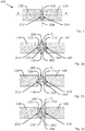
- Fig. 1 shows an expansion joint 100 between a first and a second construction element (110 and 120, respectively), in this case wall elements.
- each of the construction elements has a face (112 and 122), which faces being substantially parallel and creating a joint opening 130.
- the joint opening has a joint axis 132 substantially parallel to the faces.
- the joint comprises along this joint axis an elongated seal 200, elongated along an axis of elongation 204.
- This axis of elongation typically is coinciding or parallel to the axis of the joint.
- the elongated seal or body comprises a sheet or tube 202 comprising intumescent material.
- the sheet or tube in uncompressed state, having a wall thickness Ts and having either tubular or profiled cross section perpendicular to the axis of elongation, this is in a cross section according to plane AA'.
- the seal is installed in the joint opening by contacting the faces of the first and the second construction element by the intumescent sheet or tube along a first respectively a second contact line (210 and 212).
- the seal in some embodiments, is recessed completely in the joint opening.
- the seal is present in the joint opening in compressed state, compressed between the two faces. This compression causes an elastic deformation of the tubular or profiled cross section while the wall thickness remains substantially unchanged under the compression.
- the intumescent seal is an extruded tubular object, hence a tube, comprising flexible intumescent material, as an example graphite based intumescent material, e.g. Grafitex, available from Promat International Ltd (MY), combined with a polymer (used as plasticizer), being e.g. PVC.
- the weight ratio intumescent material/plasticizer is 50/50.
- the tubular body has a wall thickness of 1.5 mm, in uncompressed state.
- the overall external diameter of the tubular body of the tube is, in uncompressed state, 55mm.
- the intumescent tube is inserted in a joint opening with a maximum widwall tth between 20 and 50 mm.
- the same material is extruded in a larger, wider tubular body, with same sheet or wall thickness.
- the overall external diameter of the tubular body is 110 mm, in uncompressed state.
- the intumescent tubular body is inserted in a joint opening with a maximum width between 50 and 100 mm.
- a tube with an external diameter, in uncompressed state in the range of 10mm to 200mm can be provided, e.g. external diameters of 22mm, 85mm, or 110mm or even 150mm and more.
- the seal may be provided from 100% intumescent material (such as Grafitex), or with a ratio 75/25 polymer (like PVC) over intumescent material (like Grafitex).
- the polymers may be synthetic polymers, such as polyamide (nylon), polyethylene, polypropylene, polyester, polytetrafluoroethylene (Teflon) or epoxy, or natural polymers, which are usually water-based.
- Figs. 5a to 5d Alternative tubes being seals suitable for the provision of a joint according to the invention are shown in Figs. 5a to 5d .
- the tubes 202 are provided locally with thickened parts (250) at its inner surface and/or thickened parts (254) at the outer surface, also referred to as "out riggers".
- the tube 202 is provided with internal diagonal cross braces 252.
- the thickened parts or braces are provided from the same material as the other parts of the tube 202.
- the intumescent sheet may have different shapes, such as a C profile ( Fig. 2b ), a Z profile ( Fig. 2c ), a coil around the longitudinal axis ( Fig. 2d ), a P profile ( Fig. 2e ), a V profile ( Fig. 2f ), a W profile ( Fig. 2g ), or a ⁇ (lowercase beta) profile ( Figs. 2h and 2i ).
- the seal is recessed partially in the joint opening, while a leg portion 206 of the P- or ⁇ - profile extends beyond and before a face along the surface of the wall element 120.
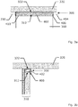
- a construction joint 300 between a wall construction element 310 and a ceiling element 320 is shown.
- the wall element has a face 312, and the ceiling element has a face 322 being substantially parallel and creating a joint opening 300.
- the joint opening has a joint axis 330 substantially parallel to the faces.
- the joint comprises along this joint axis an elongated seal 400, elongated along an axis of elongation 404.
- This axis of elongation typically is coinciding or parallel to the axis of the joint.
- the elongated seal comprises a sheet 402 comprising intumescent material.
- the intumescent sheet has the form of a P- profile.
- the leg portion 410 of the P- profile extends beyond the face 312 along the surface of the wall element 310.
- the intumescent seal comprises intumescent material which is sprayed on a carrying layer, typically a fabric or web.
- the intumescent material comprises as an example graphite based intumescent material, being about 30%w of graphite, combined with about 30%w of a thermoplastic polyolefin, about 30% of a flame retarder, e.g. sucrose or other sugars; and about 10%w of additives, such as process additives, which facilitate to a larger extent the extrusion of the mixture.
- the sheet has a wall thickness of in the range of 1 to 5 mm, e.g. 3mm, in uncompressed state.
- the overall maximum distance between the two contacting zones along which the seal is to contact the faces 322 and 312 is, in uncompressed state, 30mm. In general, maximum distance between the two contacting zones along which the seal is to contact the faces 322 and 312 is, in uncompressed state, may be in the range of 10mm to 150mm.
- Figs. 4a and 4b another alternative embodiment is shown, where the elongated seal comprises a sheet 402 comprising intumescent material.
- the intumescent sheet is similar to the one in Figs. 3a and 3b , but it has the form of a ⁇ - profile.
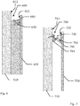
- a joint 600 being a wall cavity between a first wall construction element 610 and a second wall construction element 620 is shown.
- the first wall element has a face 612
- the second wall element has a face 622 being substantially parallel and creating a joint opening 600 being a wall cavity.
- the joint opening has a joint axis 630 substantially parallel to the faces.
- the joint comprises along this joint axis an elongated seal 602, which is identical or similar to the seal 400 shown in Figs. 4a and 4b .
- a joint 700 being a wall cavity between a first wall construction element 710 and a second wall construction element 720 is shown.
- the first wall element has a face 712
- the second wall element has a face 722 being substantially parallel and creating a joint opening 700 being a wall cavity.
- the joint opening has a joint axis 730 substantially parallel to the faces.
- the joint comprises along this joint axis an elongated seal 702, which is W-shaped.
- a support plate 704 is provided, e.g. a solid polymer plate.
- Fig. 8a shows a section of a preferred embodiment of an elongated seal as described herein.
- Fig. 8b shows a cross-section thereof (perpendicular to the axis of elongation).
- Figs. 8a and 8b both show the seal in its uncompressed state.
- the elongated seal (802) contains an intumescent material, has an E-shaped cross-section (perpendicular to the axis of elongation) and can be introduced into a joint in a similar way as the seal illustrated in Figs. 2h and 2i .
- the seal (802) comprises a first support face (831) and a second support face (832).
- the support faces (831, 832) are planar and parallel to each other, as for contacting opposing faces of (wall) construction elements forming a joint (not shown).
- the support faces (831, 832) are connected via a resilient bridge portion (833), which comprises a laterally inward rounded section.
- the bridge portion allows for relative movement of the support faces (831, 832) towards each other.
- the bridge portion does not contain holes, thus allowing for the seal to effectively close the joint.
- the seal (802) further contains a leg portion (806) for contacting a part of the construction elements outside the joint, similar as the seals shown in Fig. 2e and 2i .
- the seal (802) also contains a flange (834) which extends from the bridge portion (833).
- the outer surface of the leg portion (806) and the outer surface of the flange (834) are parallel to each other, and are separated by a gap (835).
- the leg portion (806) and flange (834) are configured such that, upon compression of the seal (by moving the support faces towards each other) when installing the seal in a joint; the gap between the leg portion and flange closes.
- the present inventors found that a seal such as shown in Figs. 8a and 8b can effectively seal a joint, thereby providing a good fire resistance and acoustic properties. It is to be understood that although preferred embodiments and/or materials have been discussed for providing embodiments according to the present invention, various modifications or changes may be made without departing from the scope and spirit of this invention.
Landscapes
- Engineering & Computer Science (AREA)
- Architecture (AREA)
- Physics & Mathematics (AREA)
- Electromagnetism (AREA)
- Civil Engineering (AREA)
- Structural Engineering (AREA)
- Building Environments (AREA)
Abstract
Description
- The present invention relates to joints between a first and a second construction element, more particular to fire protection joints, and to methods to provide fire protection joints.
- In construction, and in particular larger buildings and civil engineering structures, the design often includes structural joints in walls and ceilings, such as expansion joints which accommodate thermal and/or seismic movements of the various materials. If the walls and ceilings are also fire compartment boundaries, then also the joint seals need to have a certain fire resistance, and thus fire protection joints are required, which prevent the progression of fire in the construction.
In order to obtain a fire protection joint, it is known to press a sealing material provided with intumescent properties in the joint opening. The sealing material itself is set under pressure. A substantive amount of sealing material is necessary to ensure proper working of the seal over time. There remains a need for improved fire protection joints. - It is an object of the present invention to provide a sealed joint which provides excellent and reliable fire protection, while being easy to install.
The present inventors have found that this can be obtained by providing a joint with a specific seal. In particular, provided herein are the following aspects: - Aspect 1. A joint between a first and a second construction element, each of said construction elements having a face, said faces being substantially parallel and creating a joint opening, the joint comprising an elongated seal, elongated along an axis of elongation, said seal comprising intumescent material, said seal being, in uncompressed state, a tube or a profile, the tube or profile having a wall thickness, said seal being installed in the joint opening by contacting the faces of said first and said second construction element by said seal, said seal being compressed between said two faces, thereby elastically deforming the tubular or profiled cross section while the wall thickness remaining substantially unchanged under said compression.
- Aspect 2. The joint according to aspect 1, wherein the seal is a profiled sheet profiled perpendicularly to the axis of elongation.
- Aspect 3. The joint according to aspect 1 or 2, wherein the joint opening has a maximum width Wm, the first and second contact line defining two contact points on the profile of the seal, the distance between these two contact points measured on the profile in uncompressed state being D, Wm being equal or less than 0.97*D.
- Aspect 4. The joint according to any one of aspects 1 to 3, wherein the tube or profile has a wall thickness in the range of 0.5 to 10 mm.
- Aspect 5. The joint according to any one of aspects 1 to 4, wherein the seal is a profiled sheet, the sheet extending along the surface of at least one of the two construction elements.
- Aspect 6. The joint according to any one of aspects 1 to 5, wherein said seal comprises:
- opposing first and second support faces, each contacting one of said faces of the first and second construction elements;
- a resilient bridge portion connecting said first and second support faces; and
- a leg portion contacting a part of said first or second construction element outside said joint.
- Aspect 7. The joint according to aspect 6, wherein said seal further comprises a flange extending from said bridge portion and contacting said leg portion; wherein, in uncompressed state, said flange and leg portion are separated by a gap.
- Aspect 8. The joint according to aspect 7, wherein said flange and said leg portion each comprise an outer surface, said outer surfaces being parallel to each other.
- Aspect 9. The joint according to any one of aspects 6 to 8, wherein said bridge portion forms a closed structure.
- Aspect 10. The joint according to any one of aspects 1 to 9, wherein the joint is an expansion joint, construction joint, or wall cavity.
- Aspect 11. The joint according to any one of aspects 1 to 10, wherein said seal comprises intumescent material and polymer.
- Aspect 12. The joint according to any one of aspects 1 to 11, wherein said intumescent material comprises ammonium polyphosphate based intumescent materials, graphite-based intumescent materials, or a combination thereof.
- Aspect 13. A method for providing a fire proof joint, the method comprises the steps of:
- providing a first and a second construction element, each of said construction elements having a face, said faces being substantially parallel and creating a joint opening,
- providing an elongated seal, elongated along an axis of elongation, said seal comprising intumescent material, said seal being, in uncompressed state, a tube or a profile profiled perpendicularly to the axis of elongation, the tube or profile having a wall thickness; and
- installing in the joint opening said elongated seal by contacting the faces of said first and said second construction element by said seal, said seal being compressed between said two faces, thereby elastically deforming the tubular or profiled cross section while the wall thickness remaining substantially unchanged under said compression.
- Aspect 14. A seal for sealing a joint between a first and second construction element, said seal comprising an intumescent material and comprising:
- opposing first and second support faces for contacting opposing faces of a joint opening;
- a resilient bridge portion connecting said first and second support faces, and
- a leg portion for contacting a part of said first or second construction element outside said joint.
- Aspect 15. The seal according to aspect 14, wherein:
- said first and second support faces are parallel to each other; and
- said leg portion is perpendicular to said first and second support faces.
- The joints described herein have many advantages over prior art. Indeed, the seals can be prefabricated in a factory and hence under a controlled environment. Therefore, the seals and so the joints can be more reliably ensured to be fit for purpose and meeting the technical expectations. Moreover, the seals are easy to install and can significantly reduce the risk of erroneous on-site applicator errors. The resulting joints may also be easier to inspect and monitor with regard to correct installation; and can reduce the total amount of material needed for closing the joint.
The seals can accommodate movement between the construction elements forming the joint gap, while still ensuring fire sealing.
The joint prefabrication provides a large flexibility and variety of materials which can be used for the manufacture thereof, allowing for optimizing the joint design for the intended purpose.
In comparison with jointing material using the compression properties of foamed materials to close the joints, the joint according to the present invention, in partially expansion joints, may be subjected to many cycles of dimensional changes (e.g. expansion and shrinkage cycles), before signs of fatigue under the changing compression forces are noticeable for the elongated seal. Meanwhile, the seal can prevent fire being able to proceed through the joint when the joint is under fire exposure, even after such multiple cycles of dimensional changes.
As such, fire prevention can be guaranteed over a long period of time of the building containing the two construction elements.
The present inventors also surprisingly found that the introduction of the elongated seal in the joint opening positively influences the acoustic behavior of the construction of which the joint is part of.
The independent and dependent claims set out particular and preferred features of the invention. Features from the dependent claims may be combined with features of the independent or other dependent claims, and/or with features set out in the description above and/or hereinafter as appropriate.
The above and other characteristics, features and advantages of the present invention will become apparent from the following detailed description which illustrates, by way of example, the principles of the invention. This description is given for the sake of example only, without limiting the scope of the invention. - The accompanying Figures are provided by way of example only and should not be considered to limit the scope of the present invention. The same reference signs refer to the same, similar or analogous elements in the different figures.
- Fig. 1
- Schematic illustration of a front view of a particular embodiment of a joint (100) as described herein, between a first wall element (110) and a second wall element (120).
- Fig. 2
- Schematic illustration of a cross section of various embodiments of a joint (100) as described herein, comprising an elongated seal (200) which is tubular (
Fig. 2a ), or wherein the cross section may have a C shape (Fig. 2b ), a Z shape (Fig. 2c ), a spiral or coil shape (Fig. 2d ), a P shape, (Fig. 2e ), a V shape (Fig. 2f ), a W shape (Fig. 2g ), or a β (beta) shape (Figs. 2h and 2i ). - Fig. 3
- a, b: Schematic illustration of a construction joint (300) between a wall construction element (310) and a ceiling element (320), provided with an elongated seal (400) in the form of a P profile.
- Fig. 4
- a, b: Schematic illustration of a construction joint (300) between a wall construction element (310) and a ceiling element (320), provided with an elongated seal (400) in the form of a β profile.
- Fig. 5
- Schematic illustration of a cross section of various embodiments of a joint (100) as described herein, all comprising an elongated seal (200) having a tubular shape. The seals (200) are provided locally with thickened parts (250) (
Figs. 5a, 5c, and 5d ), or with internal diagonal cross braces (252) (Fig. 5b ). - Fig. 6
- Schematic illustration of a wall cavity between first and second wall construction elements (610 and 620) provided with an elongated seal (602) in the form of a β profile.
- Fig. 7
- Schematic illustration of a wall cavity between first and second wall construction elements (710 and 720) provided with an elongated seal (702) in the form of a W profile.
- Fig. 8
- a, b: Illustration of a section of an E-shaped elongated seal (802) according to a preferred embodiment of the joint and seal described herein.
- The present invention will be described with respect to particular embodiments.
It is to be noticed that the term "comprising", used in the claims, should not be interpreted as being restricted to the means listed thereafter; it does not exclude other elements or steps. It is thus to be interpreted as specifying the presence of the stated features, steps or components as referred to, but does not preclude the presence or addition of one or more other features, steps or components, or groups thereof. Thus, the scope of the expression "a device comprising means A and B" should not be limited to devices consisting only of components A and B. It means that with respect to the present invention, the only relevant components of the device are A and B.
The term "about" as used herein when referring to a measurable value such as a parameter, an amount, a temporal duration, and the like, is meant to encompass variations of +/-10% or less, preferably +/-5% or less, more preferably +/-1% or less, and still more preferably +/-0.1% or less of and from the specified value, insofar such variations are appropriate to perform in the disclosed invention. It is to be understood that the value to which the modifier "about" refers is itself also specifically, and preferably, disclosed. - Throughout this specification, reference to "one embodiment" or "an embodiment" are made. Such references indicate that a particular feature, described in relation to the embodiment is included in at least one embodiment of the present invention. Thus, appearances of the phrases "in one embodiment" or "in an embodiment" in various places throughout this specification are not necessarily all referring to the same embodiment, though they could. Furthermore, the particular features or characteristics may be combined in any suitable manner in one or more embodiments, as would be apparent to one of ordinary skill in the art.
- Provided herein is a joint between a first and a second construction element. The joint may be one of various types which can occur in a construction, such as expansion joints, construction joints, and wall cavities (e.g. cavities behind building facades). Accordingly, in particular embodiments, the joint may be selected from the list consisting from an expansion joint, a construction joint, or a wall cavity.
- The first and a second construction element may each be a wall element, a floor element, a ceiling element, or any combination of a wall, floor or ceiling element, window or door frames and alike. These elements may be provided from any suitable construction material, like bricks, concrete, screed, gypsum, fiber cement, etc.
The width of the joint is not critical, and the joints therefore may be wide to narrow. In particular embodiments, the joint may have a width ranging from 5 mm to 100 mm, preferably from 10 mm to 80 mm, and more preferably from 20 mm to 60 mm.
Each of the first and second construction elements has one or more faces, wherein a face of the first construction element and a face of the second construction element together form a joint opening. The faces forming the joint preferably have a planar shape. In preferred embodiments, the two faces forming the joint may be substantially parallel with each other. The term "substantially parallel" as used herein includes a deviation of up to 10° from an exact parallel orientation, preferably up to 5°, or even up to 1°. When the faces are (substantially) parallel to each other, the joint formed by the faces has a joint axis substantially parallel to the faces. The joint axis may be straight or curved. - The joint opening generally has an elongate shape, and is provided with an elongated seal, also referred to herein as "the seal", as to seal the joint opening. The term "elongated" as used herein is to be understood as being longer in one direction as compared to the other dimensions. Preferably, the length is at least 10 times the width of the seal and at least 10 times the height of the seal.
Accordingly, the elongated seal generally has a linear shape. In preferred embodiments, the elongated seal may be elongated along an axis of elongation. The axis of elongation may be straight or curved. In preferred embodiments, the axis of elongation preferably is parallel to (or even coincides with) the joint axis as described above. - The seal, when installed in the joint opening by contacting the faces of the first and the second construction element, may contact the faces at least along a first respectively a second contact line, and optionally along a wider contact surface. In particular embodiments, the parts of the seal intended to contact a face of a construction material are at least partially provided with an adhesive layer.
- The seal is typically installed in the joint opening by contacting the faces of the first and second construction element with the seal. More particularly, the seal is installed such that it contacts the first and second construction elements at least along a first and second contact line respectively, and preferably along a first and second contact surface respectively.
Typically, the seal is (slightly) compressed between the two faces. More particularly, the seal typically is (slightly) compressed between the respective faces of the first and second construction elements. This can ensure that the seal stays in place and allows the seal to effectively close the joint.
In its uncompressed state (before installation of the seal in the joint opening) the seal may have a tubular shape or may be a differently shaped elongated profile (e.g. an elongated profiled sheet). The profile is preferably profiled perpendicularly to the axis of elongation. Accordingly, the seal generally is formed as a tube or another profile (e.g. a profiled sheet).
The tube or profile has a wall thickness, which may be uniform along the entire seal, or may vary. For example, the cross-section of the seal (perpendicular to the axis of elongation) may contain portions having a different wall thickness, or may exhibit a uniform thickness along the entire cross-section. Similarly, the wall thickness at one location along the axis of elongation may be the same or different from the wall thickness at another location along the axis of elongation. In particular embodiments, the seal may have a substantially uniform thickness. More particularly, over at least 90% (preferably at least 95%) of the seal surface, the wall thickness preferably does not vary more than 20% (higher or lower) from the average wall thickness. Local deviations of more than 20% may for example be due to the presence of tapered edges and or out riggers (see further).
In case the seal is a tube, the term wall thickness (T) refers to the average thickness of the wall of the tube. In case the seal is a sheet or profile, the term wall thickness refers to the average thickness of the sheet or profile walls. The thickness in a point of the sheet, profile, or tube is the distance between said point on the surface of the sheet or tube, and the nearest point at the opposite surface of the sheet, profile or tube.
In preferred embodiments, the seal has an average wall thickness (in uncompressed state) ranging from 0.5 mm to 10 mm. In further embodiments, the average wall thickness may range from 1 mm to 10 mm, e.g. from 1 to 7.5 mm, such as ranging from 1 mm to 5 mm, e.g. from 1 mm to 3 mm, e.g. a thickness of about 1mm, 2mm, 3mm, 4mm or 5mm. - In particular embodiments, the elongated seal is recessed in its entirety in the joint opening. In other words, it does not protrude from the joint opening.
In other embodiments, the elongated seal is recessed partially in the joint opening and protrudes partially from the joint opening. For example, the elongated seal may comprise a leg portion which contacts a part of one of the construction elements outside the joint. The leg portion assists the user in the correct positioning of the seal in the joint. The leg portion also prevents the seal from being pushed in the seal too far, either during installation or thereafter. - When installed in the joint opening, i.e. in its compressed state, the seal is (elastically) deformed, leading to a deformation of its cross-section, while the wall thickness preferably remains substantially unchanged under the compression. The expression "substantially unchanged" means that on any point on the seal, the wall thickness changes at most 10%, more preferably at most 5% (increase or decrease) under the compression. The fact that the wall thickness remains substantially unchanged means that the walls are not substantially compressed by the compression forces exercised by the two faces of the two construction elements when the seal is installed in the joint. The seal generally is elastically deformed due to the compression, which means that it will substantially return to its original shape upon release of the compressive force. The use of an elastic material allows the joints to accommodate for relative movement between the first and second construction elements.
- As the seal is compressed, the width and/or height of the seal typically change when installing the seal in the joint opening. Also the shape of the cross-section may change to some extent.
As used herein, the distance D is the distance (averaged over all contact points), measured in uncompressed state of the seal, between a first contact point contacting the face of the first construction element and the nearest contact point contacting the face of the second construction element. The term "contact point" as used herein refers to a point on a part of the seal surface which is in contact with a face of the first or second construction element. As used herein, Wm is the maximum width of the joint opening.
In preferred embodiments, Wm is equal to or less than 0.97*D.
In particular embodiments, Wm also is equal to or less than n*T, wherein - T is the average wall thickness of the uncompressed seal; and
- n equals the maximum number of times an imaginary line from a first contact point contacting the face of the first construction element to the nearest contact point contacting the face of the second construction element.
- As described above, in particular embodiments, the seal may be a tube, i.e. have a tubular shape. The tube can be a circular or oval tube or a polygonal tube, such as triangular, square or rectangular, pentagonal, hexagonal or polygonal tube. Optionally the tube may be provided with internal diagonal cross braces, usually made from the same material. Further or alternatively, the tube may be provided locally with thickened parts at its inner and/or outer surface. At the outer surface, such thickenings may be referred to as "out riggers".
- As described above, in particular embodiments, the seal may be a profile, more particularly a profiled sheet, which is profiled perpendicularly to the axis of elongation. In particular embodiments, the profile may be selected from the group consisting of E profiles; S profiles; Z profiles; V profiles; W profiles; C profiles; omega profiles; P profiles; B profiles; β (lowercase beta) profiles; D profiles; Zigzag profiles; sinusoidally undulated profile; and coils coiled around the longitudinal axis. The coils may be rectangularly, polygonally or circularly profiled coils.
The shape and size of the cross-section of the seal preferably remains substantially uniform along the axis of elongation. - In particular embodiments, the seal is an elongate seal, more particularly an elongate profile, comprising:
- opposing first and second support faces for contacting opposing faces of a joint opening;
- a resilient bridge portion connecting said first and second support faces, and
- optionally, a leg portion for contacting a part of said first or second construction element outside said joint.
- The opposing first and second support faces allow for contacting the joint faces along a contact surface as described above. The support faces preferably have a planar shape. The first and second support faces are generally spaced apart from each other, thus forming a gap in between. The faces are connected via the bridge portion, which spans that gap.
- The resilience of the bridge portion can allow the seal to accommodate relative movements between the joint faces (mainly towards or away from each other), without damaging the seal or causing significant compression of the seal walls. In order to increase the resilience, the bridge portion may comprise an angled and/or rounded cross-section. In particular embodiments, the bridge portion may comprise a laterally inward angled and/or rounded section.
The bridge portion preferably forms a closed structure, i.e. does not contain openings or holes. In this way, the bridge portion can (together with the first and second support faces) effectively close the joint. This can further improve the fire resistance and acoustic properties of the joint. - The leg portion is typically provided such that when the seal contacts the joint faces via the first and second support faces, the leg portion contacts a part of the first or second construction element outside (but adjacent to) the joint. As described above, the leg portion can assist the user in correctly positioning the seal in the joint and prevent the seal from being pushed in the seal too far.
Typically, the construction element contacted by the leg portion is a wall, wherein the leg portion contacts a part of the wall surface (outside the joint).
The leg portion preferably has a planar shape with on one side an inner surface and on the opposite side an outer surface. Typically, at least a part of the inner surface is intended for contacting a construction element. In preferred embodiments, the leg portion has a perpendicular orientation with respect to the (planar) first and second support faces. The term "perpendicular" as used herein may include deviations of up to 15° from a perfect perpendicular orientation, preferably up to 10°, more preferably up to 5°, and most preferably up to 1°.
The leg portion typically extends from the first support face, the second support face, or the bridge portion. Preferably it extends from the first or second support face. In particular embodiments, the leg portion may span the entire gap between the first and second support face, e.g. as shown inFigs. 2e ,2h, and 2i . In this way, the leg portion remains the only visible part of the joint and seal. In other embodiments, the leg portion does not extend into the area between the two support faces, or only partially extends into that area. - In particular embodiments, the seal may further be provided with one or more flanges comprising an outer surface having an orientation which is parallel to the outer and/or inner surface of the leg portion. Each flange is typically connected to the bridge portion, or to one of the support faces (more particularly the support face which is not provided with the leg portion).
In embodiments wherein the leg portion spans the entire gap (or a significant portion thereof) between the first and second support face, the flange(s) may act as a support for the leg portion.
The outer surface of the flange(s) is (almost) coplanar with the inner surface of the leg portion, such that the outer surface of the flange then can contact (a part of) the inner surface of the leg portion.
In other embodiments (wherein the leg portion extends at most partially into the gap between the support faces), the seal may comprise a flange which is separated from the leg portion by a gap. The flange and leg portion are typically positioned such that, upon compression of the seal (by moving the support faces towards each other, e.g. when positioning the seal into a joint opening), the leg portion and flange move towards each other, thus allowing the gap to close. That way, the leg portion and flange may remain the only visible portions of the seal.
Preferably the leg portion and flange are allowed to slide over each other, such that the gap can be closed at different levels of compression. In particular embodiments, the flange and/or leg portion may comprise tapered edges, which can make such sliding easier. - In particular embodiments, the outer surface of the leg portion may be provided with a coating, e.g. a decorative coating or primer layer. The flange(s), if present, may also be provided with such coating.
- The seal of the joint described herein comprises an intumescent material. In preferred embodiments, the seal, when installed in the joint opening as described above, may (directly) contact the faces of the first and second construction element via the intumescent material. Preferably, the intumescent material is present along at least one outer surface of the seal.
The intumescent material may be any suitable intumescent material as known in the art. In particular embodiments, the intumescent material is selected from the list consisting of a graphite based intumescent material (such as swelling graphite), an ammonium polyphosphate based intumescent material, and combinations thereof. In preferred embodiments, the intumescent material comprises a graphite based intumescent material.
The intumescent material may comprise non-flammable materials, flammable materials, or a combination thereof.
In addition to the intumescent material, the seal preferably further comprises a polymer material. The polymer can act as binder for the intumescent material and/or as plasticizer. Preferably the weight ratio polymer/intumescent material ranges from 10/90 to 90/10, more preferred between 20/80 and 80/20, or even between 25/75 and 75/25, or between 40/60 and 60/40 such as 50/50. The one or more polymers may be selected from synthetic polymers and natural polymers. In particular embodiments, the one or more polymers may be selected from the group consisting of poly(vinyl chloride), polyamides, polyolefins (such as polyethylene, polypropylene, and the like), polyesters, polytetrafluoroethylene, and polyepoxides. - In particular embodiments, the seal may further comprise (in addition to the intumescent material and optional polymer(s)) one or more additives, such a flame retarder, an extrusion promoting product. In particular embodiments, the seal may comprise one or more additives selected from the list consisting of sucrose, fructose, and pentaerythritol.
- The seal may be made of a foamed or non-foamed material. Preferably, the seal is made of a non-foamed material.
- The seal may comprise one or more layered walls. More particularly, the walls may comprise at least one layer comprising an intumescent material, and at least one supporting layer or carrier layer. Examples of suitable carrier layers include a textile fabric or web, a layer of polymeric material, a non- or low combustible material (such as material complying with the specification for non-combustibility in AS1530.1,BS476.6, EN1182 and/or ASTM ED136) or a metallic strip. The layer(s) comprising intumescent material may be provided onto the carrier layer via known processes including but not limited to spraying or extrusion. When present, a carrier layer may provide the part of the seal surface where it is intended to contact one or both faces of the first and/or the second construction element. In particular embodiments, the seal may comprise a carrier layer which comprises an adhesive layer.
- In particular embodiments, the seal may be may be an extruded profile or tube. Optionally, reinforcing elements like reinforcing wires or yarns may be included during extrusion. Optionally, a layer comprising intumescent material may be extruded upon one or more other layer, such as a carrier layer as described above.
- The parts or layers of the seal comprising the intumescent material preferably have a density in the range from 500 kg/m3 to 2000 kg/m3, preferably in the range from 850 kg/m3 to 1300 kg/m3.
Further provided herein is a method of providing a fire proof joint. The method comprises the steps of: - providing a first and a second construction element, each of said construction elements having a face, said faces being substantially parallel and creating a joint opening,
- providing an elongated seal, elongated along an axis of elongation, said seal comprising intumescent material, said seal being, in uncompressed state, a tube or an elongate profile (e.g. a profiled sheet profiled perpendicularly to the axis of elongation), the tube or profile having a wall thickness; and
- installing in the joint opening said elongated seal by contacting the faces of said first and said second construction element by said seal, said seal being compressed between said two faces, thereby elastically deforming the tubular or profiled cross section while the wall thickness remaining substantially unchanged under said compression.
- The elongated seal may be provided at long length, optionally as a wrapped or coiled seal, and optionally enclosed in a suitable packaging. The elongated seal can be cut of at the length necessary to close the joint along its entire or part of its length.
- Further provided herein is a seal suitable for use in a joint as described herein. In particular embodiments, the seal is an elongate seal, more particularly an elongate profile, comprising:
- opposing first and second support faces for contacting opposing faces of a joint opening;
- a resilient bridge portion connecting said first and second support faces, and
- optionally, a leg portion for contacting a part of said first or second construction element outside said joint.
- The following examples are provided for the purpose of illustrating the present invention and by no means are meant and in no way should be interpreted to limit the scope of the present invention.
-
Fig. 1 shows anexpansion joint 100 between a first and a second construction element (110 and 120, respectively), in this case wall elements. As more readily visible inFigs. 2a to 2g , each of the construction elements has a face (112 and 122), which faces being substantially parallel and creating ajoint opening 130. The joint opening has ajoint axis 132 substantially parallel to the faces. - As shown in
Figs. 2a to 2i , the joint comprises along this joint axis anelongated seal 200, elongated along an axis ofelongation 204. This axis of elongation typically is coinciding or parallel to the axis of the joint. The elongated seal or body comprises a sheet ortube 202 comprising intumescent material. - The sheet or tube, in uncompressed state, having a wall thickness Ts and having either tubular or profiled cross section perpendicular to the axis of elongation, this is in a cross section according to plane AA'. The seal is installed in the joint opening by contacting the faces of the first and the second construction element by the intumescent sheet or tube along a first respectively a second contact line (210 and 212). The seal, in some embodiments, is recessed completely in the joint opening. The seal is present in the joint opening in compressed state, compressed between the two faces. This compression causes an elastic deformation of the tubular or profiled cross section while the wall thickness remains substantially unchanged under the compression.
- In
Fig. 2a , the intumescent seal is an extruded tubular object, hence a tube, comprising flexible intumescent material, as an example graphite based intumescent material, e.g. Grafitex, available from Promat International Ltd (MY), combined with a polymer (used as plasticizer), being e.g. PVC. The weight ratio intumescent material/plasticizer is 50/50. The tubular body has a wall thickness of 1.5 mm, in uncompressed state. The overall external diameter of the tubular body of the tube is, in uncompressed state, 55mm. The intumescent tube is inserted in a joint opening with a maximum widwall tth between 20 and 50 mm. - In an alternative embodiment, the same material is extruded in a larger, wider tubular body, with same sheet or wall thickness. The overall external diameter of the tubular body is 110 mm, in uncompressed state. The intumescent tubular body is inserted in a joint opening with a maximum width between 50 and 100 mm.
In general, a tube with an external diameter, in uncompressed state, in the range of 10mm to 200mm can be provided, e.g. external diameters of 22mm, 85mm, or 110mm or even 150mm and more.
As alternative embodiments, the seal may be provided from 100% intumescent material (such as Grafitex), or with a ratio 75/25 polymer (like PVC) over intumescent material (like Grafitex). The polymers may be synthetic polymers, such as polyamide (nylon), polyethylene, polypropylene, polyester, polytetrafluoroethylene (Teflon) or epoxy, or natural polymers, which are usually water-based. - Alternative tubes being seals suitable for the provision of a joint according to the invention are shown in
Figs. 5a to 5d . InFigs. 5a, 5c and 5d , thetubes 202 are provided locally with thickened parts (250) at its inner surface and/or thickened parts (254) at the outer surface, also referred to as "out riggers". InFig. 5b , thetube 202 is provided with internal diagonal cross braces 252. In allFigs. 5a to 5d , the thickened parts or braces are provided from the same material as the other parts of thetube 202. - The intumescent sheet may have different shapes, such as a C profile (
Fig. 2b ), a Z profile (Fig. 2c ), a coil around the longitudinal axis (Fig. 2d ), a P profile (Fig. 2e ), a V profile (Fig. 2f ), a W profile (Fig. 2g ), or a β (lowercase beta) profile (Figs. 2h and 2i ). - As seen in
Figs. 2e and2i , the seal is recessed partially in the joint opening, while aleg portion 206 of the P- or β- profile extends beyond and before a face along the surface of thewall element 120. - In
Figs. 3a and 3b , a construction joint 300 between awall construction element 310 and aceiling element 320 is shown. The wall element has aface 312, and the ceiling element has aface 322 being substantially parallel and creating ajoint opening 300. The joint opening has ajoint axis 330 substantially parallel to the faces. - The joint comprises along this joint axis an
elongated seal 400, elongated along an axis ofelongation 404. This axis of elongation typically is coinciding or parallel to the axis of the joint. The elongated seal comprises asheet 402 comprising intumescent material. The intumescent sheet has the form of a P- profile. Theleg portion 410 of the P- profile extends beyond theface 312 along the surface of thewall element 310. The intumescent seal comprises intumescent material which is sprayed on a carrying layer, typically a fabric or web. The intumescent material comprises as an example graphite based intumescent material, being about 30%w of graphite, combined with about 30%w of a thermoplastic polyolefin, about 30% of a flame retarder, e.g. sucrose or other sugars; and about 10%w of additives, such as process additives, which facilitate to a larger extent the extrusion of the mixture.
The sheet has a wall thickness of in the range of 1 to 5 mm, e.g. 3mm, in uncompressed state. The overall maximum distance between the two contacting zones along which the seal is to contact thefaces faces - In
Figs. 4a and 4b , another alternative embodiment is shown, where the elongated seal comprises asheet 402 comprising intumescent material. The intumescent sheet is similar to the one inFigs. 3a and 3b , but it has the form of a β- profile. - In
Fig. 6 , a joint 600 being a wall cavity between a firstwall construction element 610 and a secondwall construction element 620 is shown. The first wall element has aface 612, and the second wall element has aface 622 being substantially parallel and creating ajoint opening 600 being a wall cavity. The joint opening has ajoint axis 630 substantially parallel to the faces. The joint comprises along this joint axis anelongated seal 602, which is identical or similar to theseal 400 shown inFigs. 4a and 4b . - In
Fig. 7 , a joint 700 being a wall cavity between a firstwall construction element 710 and a secondwall construction element 720 is shown. The first wall element has aface 712, and the second wall element has aface 722 being substantially parallel and creating ajoint opening 700 being a wall cavity. The joint opening has ajoint axis 730 substantially parallel to the faces. The joint comprises along this joint axis anelongated seal 702, which is W-shaped. At one side of the W-shape, asupport plate 704 is provided, e.g. a solid polymer plate. By means of a fixing means, e.g. a nail or screw 706, the seal can be fixed to the face of one of the wall construction elements, in this embodiment the firstwall construction element 710. -
Fig. 8a shows a section of a preferred embodiment of an elongated seal as described herein.Fig. 8b shows a cross-section thereof (perpendicular to the axis of elongation).Figs. 8a and 8b both show the seal in its uncompressed state. The elongated seal (802) contains an intumescent material, has an E-shaped cross-section (perpendicular to the axis of elongation) and can be introduced into a joint in a similar way as the seal illustrated inFigs. 2h and 2i . The seal (802) comprises a first support face (831) and a second support face (832). The support faces (831, 832) are planar and parallel to each other, as for contacting opposing faces of (wall) construction elements forming a joint (not shown). The support faces (831, 832) are connected via a resilient bridge portion (833), which comprises a laterally inward rounded section. The bridge portion allows for relative movement of the support faces (831, 832) towards each other. The bridge portion does not contain holes, thus allowing for the seal to effectively close the joint. The seal (802) further contains a leg portion (806) for contacting a part of the construction elements outside the joint, similar as the seals shown inFig. 2e and2i .
The seal (802) also contains a flange (834) which extends from the bridge portion (833). The outer surface of the leg portion (806) and the outer surface of the flange (834) are parallel to each other, and are separated by a gap (835). The leg portion (806) and flange (834) are configured such that, upon compression of the seal (by moving the support faces towards each other) when installing the seal in a joint; the gap between the leg portion and flange closes. The present inventors found that a seal such as shown inFigs. 8a and 8b can effectively seal a joint, thereby providing a good fire resistance and acoustic properties.
It is to be understood that although preferred embodiments and/or materials have been discussed for providing embodiments according to the present invention, various modifications or changes may be made without departing from the scope and spirit of this invention.
More particularly, Wm typically is equal to or less than the lower of 0.97*D and n*T. In particular embodiments, Wm ranges from 0.2*D to 0.97*D, preferably from 0.3*D to 0.95*D.
Claims (15)
- A joint between a first and a second construction element, each of said construction elements having a face, said faces being substantially parallel and creating a joint opening, the joint comprising an elongated seal, elongated along an axis of elongation, said seal comprising intumescent material, said seal being, in uncompressed state, a tube or a profile, the tube or profile having a wall thickness, said seal being installed in the joint opening by contacting the faces of said first and said second construction element by said seal, said seal being compressed between said two faces, thereby elastically deforming the tubular or profiled cross section while the wall thickness remaining substantially unchanged under said compression.
- The joint according to claim 1, wherein the seal is a profiled sheet profiled perpendicularly to the axis of elongation.
- The joint according to claim 1 or 2, wherein the joint opening has a maximum width Wm, the first and second contact line defining two contact points on the profile of the seal, the distance between these two contact points measured on the profile in uncompressed state being D, Wm being equal or less than 0.97*D.
- The joint according to any one of claims 1 to 3, wherein the tube or profile has a wall thickness in the range of 0.5 to 10 mm.
- The joint according to any one of claims 1 to 4, wherein the seal is a profiled sheet, the sheet extending along the surface of at least one of the two construction elements.
- The joint according to any one of claims 1 to 5, wherein said seal comprises:- opposing first and second support faces, each contacting one of said faces of the first and second construction elements;- a resilient bridge portion connecting said first and second support faces; and- a leg portion contacting a part of said first or second construction element outside said joint.
- The joint according to claim 6, wherein said seal further comprises a flange extending from said bridge portion and contacting said leg portion; wherein, in uncompressed state, said flange and leg portion are separated by a gap.
- The joint according to claim 7, wherein said flange and said leg portion each comprise an outer surface, said outer surfaces being parallel to each other.
- The joint according to any one of claims 6 to 8, wherein said bridge portion forms a closed structure.
- The joint according to any one of claims 1 to 9, wherein the joint is an expansion joint, construction joint, or wall cavity.
- The joint according to any one of claims 1 to 10, wherein said seal comprises intumescent material and polymer.
- The joint according to any one of claims 1 to 11, wherein said intumescent material comprises ammonium polyphosphate based intumescent materials, graphite-based intumescent materials, or a combination thereof.
- A method for providing a fire proof joint, the method comprises the steps of:- providing a first and a second construction element, each of said construction elements having a face, said faces being substantially parallel and creating a joint opening,- providing an elongated seal, elongated along an axis of elongation, said seal comprising intumescent material, said seal being, in uncompressed state, a tube or a profile profiled perpendicularly to the axis of elongation, the tube or profile having a wall thickness; and- installing in the joint opening said elongated seal by contacting the faces of said first and said second construction element by said seal, said seal being compressed between said two faces, thereby elastically deforming the tubular or profiled cross section while the wall thickness remaining substantially unchanged under said compression.
- An elongated seal for sealing a joint between a first and second construction element, said seal comprising an intumescent material and comprising:- opposing first and second support faces for contacting opposing faces of a joint opening;- a resilient bridge portion connecting said first and second support faces, and- a leg portion for contacting a part of said first or second construction element outside said joint.
- The elongated seal according to claim 14, wherein:- said first and second support faces are parallel to each other; and- said leg portion is perpendicular to said first and second support faces.
Priority Applications (2)
| Application Number | Priority Date | Filing Date | Title |
|---|---|---|---|
| EP18178889.4A EP3584381B1 (en) | 2018-06-20 | 2018-06-20 | Fire protection joint |
| AU2019204003A AU2019204003B2 (en) | 2018-06-20 | 2019-06-07 | Fire protection joint |
Applications Claiming Priority (1)
| Application Number | Priority Date | Filing Date | Title |
|---|---|---|---|
| EP18178889.4A EP3584381B1 (en) | 2018-06-20 | 2018-06-20 | Fire protection joint |
Publications (2)
| Publication Number | Publication Date |
|---|---|
| EP3584381A1 true EP3584381A1 (en) | 2019-12-25 |
| EP3584381B1 EP3584381B1 (en) | 2025-08-13 |
Family
ID=62715970
Family Applications (1)
| Application Number | Title | Priority Date | Filing Date |
|---|---|---|---|
| EP18178889.4A Active EP3584381B1 (en) | 2018-06-20 | 2018-06-20 | Fire protection joint |
Country Status (2)
| Country | Link |
|---|---|
| EP (1) | EP3584381B1 (en) |
| AU (1) | AU2019204003B2 (en) |
Cited By (12)
| Publication number | Priority date | Publication date | Assignee | Title |
|---|---|---|---|---|
| CN113152699A (en) * | 2020-01-22 | 2021-07-23 | 美国博宁公司 | Structural gap filler and related methods of use |
| US20220056686A1 (en) * | 2020-08-19 | 2022-02-24 | California Expanded Metal Products Company | Building joint with compressible firestopping component |
| WO2022043219A1 (en) * | 2020-08-24 | 2022-03-03 | Hilti Aktiengesellschaft | Sealing device for edge joint of a drywall, drywall, and method for producing a drywall |
| EP3974593A1 (en) | 2020-09-29 | 2022-03-30 | Hilti Aktiengesellschaft | Sealing element for a joint of a structure |
| CN116591345A (en) * | 2022-02-04 | 2023-08-15 | 美国博宁公司 | Structural barriers and related methods of use |
| JP2023122241A (en) * | 2022-02-22 | 2023-09-01 | イイダ産業株式会社 | Thermally expandable refractory molding |
| JP2023173576A (en) * | 2022-05-26 | 2023-12-07 | Jfeシビル株式会社 | Exterior wall panels, exterior wall structures using the same, and construction methods for exterior wall panels |
| US12024882B2 (en) | 2020-01-22 | 2024-07-02 | Bohning Company, Ltd. | Structural barrier and related method of use |
| US12215498B2 (en) | 2012-01-20 | 2025-02-04 | Cemco, Llc | Fire-rated joint system |
| US12428836B2 (en) | 2010-04-08 | 2025-09-30 | Cemco, Llc | Fire-rated wall construction product |
| US12607009B2 (en) | 2021-12-27 | 2026-04-21 | Cemco, Llc | Fire-rated gaskets and wall assemblies |
| US12680297B2 (en) | 2018-08-16 | 2026-07-14 | Cemco, Llc | Fire or sound blocking components and wall assemblies with fire or sound blocking components |
Citations (3)
| Publication number | Priority date | Publication date | Assignee | Title |
|---|---|---|---|---|
| WO2008028219A1 (en) * | 2006-09-08 | 2008-03-13 | Boss Polymer Technologies Pty Ltd | Joint seal |
| US20110011019A1 (en) * | 2009-07-14 | 2011-01-20 | Specified Technologies Inc. | Firestopping sealing means for use with gypsum wallboard in head-of-wall construction |
| EP3056626A1 (en) * | 2015-02-13 | 2016-08-17 | HILTI Aktiengesellschaft | Sealing tape with predetermined geometry and sealing assembly comprising such a sealing tape |
-
2018
- 2018-06-20 EP EP18178889.4A patent/EP3584381B1/en active Active
-
2019
- 2019-06-07 AU AU2019204003A patent/AU2019204003B2/en active Active
Patent Citations (3)
| Publication number | Priority date | Publication date | Assignee | Title |
|---|---|---|---|---|
| WO2008028219A1 (en) * | 2006-09-08 | 2008-03-13 | Boss Polymer Technologies Pty Ltd | Joint seal |
| US20110011019A1 (en) * | 2009-07-14 | 2011-01-20 | Specified Technologies Inc. | Firestopping sealing means for use with gypsum wallboard in head-of-wall construction |
| EP3056626A1 (en) * | 2015-02-13 | 2016-08-17 | HILTI Aktiengesellschaft | Sealing tape with predetermined geometry and sealing assembly comprising such a sealing tape |
Cited By (17)
| Publication number | Priority date | Publication date | Assignee | Title |
|---|---|---|---|---|
| US12428836B2 (en) | 2010-04-08 | 2025-09-30 | Cemco, Llc | Fire-rated wall construction product |
| US12215498B2 (en) | 2012-01-20 | 2025-02-04 | Cemco, Llc | Fire-rated joint system |
| US12680297B2 (en) | 2018-08-16 | 2026-07-14 | Cemco, Llc | Fire or sound blocking components and wall assemblies with fire or sound blocking components |
| EP3854954A1 (en) * | 2020-01-22 | 2021-07-28 | Bohning Company, Ltd. | Structural gap filler and related method of use |
| CN113152699A (en) * | 2020-01-22 | 2021-07-23 | 美国博宁公司 | Structural gap filler and related methods of use |
| US11306476B2 (en) | 2020-01-22 | 2022-04-19 | Bohning Company, Ltd. | Structural gap filler and related method of use |
| US12024882B2 (en) | 2020-01-22 | 2024-07-02 | Bohning Company, Ltd. | Structural barrier and related method of use |
| US20220056686A1 (en) * | 2020-08-19 | 2022-02-24 | California Expanded Metal Products Company | Building joint with compressible firestopping component |
| US12454824B2 (en) * | 2020-08-19 | 2025-10-28 | Cemco, Llc | Building joint with compressible firestopping component |
| WO2022043219A1 (en) * | 2020-08-24 | 2022-03-03 | Hilti Aktiengesellschaft | Sealing device for edge joint of a drywall, drywall, and method for producing a drywall |
| US12392132B2 (en) | 2020-08-24 | 2025-08-19 | Hilti Aktiengesellschaft | Sealing device for the edge joint of drywall, drywall, as well as a method for producing drywall |
| EP3974593A1 (en) | 2020-09-29 | 2022-03-30 | Hilti Aktiengesellschaft | Sealing element for a joint of a structure |
| WO2022069220A1 (en) | 2020-09-29 | 2022-04-07 | Hilti Aktiengesellschaft | Sealing element for a construction joint |
| US12607009B2 (en) | 2021-12-27 | 2026-04-21 | Cemco, Llc | Fire-rated gaskets and wall assemblies |
| CN116591345A (en) * | 2022-02-04 | 2023-08-15 | 美国博宁公司 | Structural barriers and related methods of use |
| JP2023122241A (en) * | 2022-02-22 | 2023-09-01 | イイダ産業株式会社 | Thermally expandable refractory molding |
| JP2023173576A (en) * | 2022-05-26 | 2023-12-07 | Jfeシビル株式会社 | Exterior wall panels, exterior wall structures using the same, and construction methods for exterior wall panels |
Also Published As
| Publication number | Publication date |
|---|---|
| AU2019204003B2 (en) | 2024-12-05 |
| EP3584381B1 (en) | 2025-08-13 |
| AU2019204003A1 (en) | 2020-01-16 |
Similar Documents
| Publication | Publication Date | Title |
|---|---|---|
| AU2019204003B2 (en) | Fire protection joint | |
| US12428836B2 (en) | Fire-rated wall construction product | |
| US9856641B2 (en) | Expansion joint for longitudinal load transfer | |
| US8151526B2 (en) | Head-of-wall fireblock systems and related wall assemblies | |
| US9683364B2 (en) | Fire-rated wall construction product | |
| US8056293B2 (en) | Head-of-wall fireblock systems and related wall assemblies | |
| US7866108B2 (en) | Head-of-wall fireblock systems and related wall assemblies | |
| US9512614B2 (en) | Insulating sealing element for construction joints | |
| US9982428B2 (en) | Expansion joint seal with surface load transfer, intumescent, and internal sensor | |
| US6125608A (en) | Composite insulated framing members and envelope extension system for buildings | |
| US20110214371A1 (en) | Offset leg framing element for fire stop applications | |
| US20150275506A1 (en) | Insulating sealing element for head-of-wall joints | |
| US11313118B2 (en) | Expansion joint seal with splicing system | |
| US20260035909A1 (en) | Sealing device for edge joints and drywall | |
| US12392132B2 (en) | Sealing device for the edge joint of drywall, drywall, as well as a method for producing drywall | |
| US20220034081A1 (en) | Gasket sealing arrangements | |
| NZ754379A (en) | Fire protection joint | |
| KR102282046B1 (en) | Inside wall and inside wall construction method using the same | |
| CA2962478A1 (en) | Fire-rated wall construction product | |
| AU2018205148A1 (en) | Expansion joint |
Legal Events
| Date | Code | Title | Description |
|---|---|---|---|
| PUAI | Public reference made under article 153(3) epc to a published international application that has entered the european phase |
Free format text: ORIGINAL CODE: 0009012 |
|
| STAA | Information on the status of an ep patent application or granted ep patent |
Free format text: STATUS: THE APPLICATION HAS BEEN PUBLISHED |
|
| AK | Designated contracting states |
Kind code of ref document: A1 Designated state(s): AL AT BE BG CH CY CZ DE DK EE ES FI FR GB GR HR HU IE IS IT LI LT LU LV MC MK MT NL NO PL PT RO RS SE SI SK SM TR |
|
| AX | Request for extension of the european patent |
Extension state: BA ME |
|
| STAA | Information on the status of an ep patent application or granted ep patent |
Free format text: STATUS: REQUEST FOR EXAMINATION WAS MADE |
|
| 17P | Request for examination filed |
Effective date: 20200625 |
|
| RBV | Designated contracting states (corrected) |
Designated state(s): AL AT BE BG CH CY CZ DE DK EE ES FI FR GB GR HR HU IE IS IT LI LT LU LV MC MK MT NL NO PL PT RO RS SE SI SK SM TR |
|
| STAA | Information on the status of an ep patent application or granted ep patent |
Free format text: STATUS: EXAMINATION IS IN PROGRESS |
|
| 17Q | First examination report despatched |
Effective date: 20220914 |
|
| GRAP | Despatch of communication of intention to grant a patent |
Free format text: ORIGINAL CODE: EPIDOSNIGR1 |
|
| STAA | Information on the status of an ep patent application or granted ep patent |
Free format text: STATUS: GRANT OF PATENT IS INTENDED |
|
| INTG | Intention to grant announced |
Effective date: 20250219 |
|
| RIN1 | Information on inventor provided before grant (corrected) |
Inventor name: GAUCH, EDWIN S. Inventor name: PORTER, RAYMOND |
|
| RAP1 | Party data changed (applicant data changed or rights of an application transferred) |
Owner name: ETEX AUSTRALIA PTY LTD |
|
| GRAS | Grant fee paid |
Free format text: ORIGINAL CODE: EPIDOSNIGR3 |
|
| RAP1 | Party data changed (applicant data changed or rights of an application transferred) |
Owner name: ETEX BUILDING PERFORMANCE GMBH Owner name: ETEX AUSTRALIA PTY LTD |
|
| GRAA | (expected) grant |
Free format text: ORIGINAL CODE: 0009210 |
|
| STAA | Information on the status of an ep patent application or granted ep patent |
Free format text: STATUS: THE PATENT HAS BEEN GRANTED |
|
| AK | Designated contracting states |
Kind code of ref document: B1 Designated state(s): AL AT BE BG CH CY CZ DE DK EE ES FI FR GB GR HR HU IE IS IT LI LT LU LV MC MK MT NL NO PL PT RO RS SE SI SK SM TR |
|
| REG | Reference to a national code |
Ref country code: GB Ref legal event code: FG4D |
|
| REG | Reference to a national code |
Ref country code: CH Ref legal event code: EP |
|
| REG | Reference to a national code |
Ref country code: DE Ref legal event code: R096 Ref document number: 602018084495 Country of ref document: DE |
|
| REG | Reference to a national code |
Ref country code: IE Ref legal event code: FG4D |
|
| P01 | Opt-out of the competence of the unified patent court (upc) registered |
Free format text: CASE NUMBER: UPC_APP_5806_3584381/2025 Effective date: 20250903 |
|
| REG | Reference to a national code |
Ref country code: NL Ref legal event code: MP Effective date: 20250813 |
|
| PG25 | Lapsed in a contracting state [announced via postgrant information from national office to epo] |
Ref country code: IS Free format text: LAPSE BECAUSE OF FAILURE TO SUBMIT A TRANSLATION OF THE DESCRIPTION OR TO PAY THE FEE WITHIN THE PRESCRIBED TIME-LIMIT Effective date: 20251213 |
|
| PG25 | Lapsed in a contracting state [announced via postgrant information from national office to epo] |
Ref country code: NO Free format text: LAPSE BECAUSE OF FAILURE TO SUBMIT A TRANSLATION OF THE DESCRIPTION OR TO PAY THE FEE WITHIN THE PRESCRIBED TIME-LIMIT Effective date: 20251113 |
|
| REG | Reference to a national code |
Ref country code: LT Ref legal event code: MG9D |
|
| PG25 | Lapsed in a contracting state [announced via postgrant information from national office to epo] |
Ref country code: PT Free format text: LAPSE BECAUSE OF FAILURE TO SUBMIT A TRANSLATION OF THE DESCRIPTION OR TO PAY THE FEE WITHIN THE PRESCRIBED TIME-LIMIT Effective date: 20251215 |
|
| PG25 | Lapsed in a contracting state [announced via postgrant information from national office to epo] |
Ref country code: FI Free format text: LAPSE BECAUSE OF FAILURE TO SUBMIT A TRANSLATION OF THE DESCRIPTION OR TO PAY THE FEE WITHIN THE PRESCRIBED TIME-LIMIT Effective date: 20250813 |
|
| PG25 | Lapsed in a contracting state [announced via postgrant information from national office to epo] |
Ref country code: NL Free format text: LAPSE BECAUSE OF FAILURE TO SUBMIT A TRANSLATION OF THE DESCRIPTION OR TO PAY THE FEE WITHIN THE PRESCRIBED TIME-LIMIT Effective date: 20250813 Ref country code: HR Free format text: LAPSE BECAUSE OF FAILURE TO SUBMIT A TRANSLATION OF THE DESCRIPTION OR TO PAY THE FEE WITHIN THE PRESCRIBED TIME-LIMIT Effective date: 20250813 |
|
| PG25 | Lapsed in a contracting state [announced via postgrant information from national office to epo] |
Ref country code: GR Free format text: LAPSE BECAUSE OF FAILURE TO SUBMIT A TRANSLATION OF THE DESCRIPTION OR TO PAY THE FEE WITHIN THE PRESCRIBED TIME-LIMIT Effective date: 20251114 |
|
| PG25 | Lapsed in a contracting state [announced via postgrant information from national office to epo] |
Ref country code: SE Free format text: LAPSE BECAUSE OF FAILURE TO SUBMIT A TRANSLATION OF THE DESCRIPTION OR TO PAY THE FEE WITHIN THE PRESCRIBED TIME-LIMIT Effective date: 20250813 |
|
| PG25 | Lapsed in a contracting state [announced via postgrant information from national office to epo] |
Ref country code: LV Free format text: LAPSE BECAUSE OF FAILURE TO SUBMIT A TRANSLATION OF THE DESCRIPTION OR TO PAY THE FEE WITHIN THE PRESCRIBED TIME-LIMIT Effective date: 20250813 |
|
| PG25 | Lapsed in a contracting state [announced via postgrant information from national office to epo] |
Ref country code: BG Free format text: LAPSE BECAUSE OF FAILURE TO SUBMIT A TRANSLATION OF THE DESCRIPTION OR TO PAY THE FEE WITHIN THE PRESCRIBED TIME-LIMIT Effective date: 20250813 Ref country code: PL Free format text: LAPSE BECAUSE OF FAILURE TO SUBMIT A TRANSLATION OF THE DESCRIPTION OR TO PAY THE FEE WITHIN THE PRESCRIBED TIME-LIMIT Effective date: 20250813 |
|
| PG25 | Lapsed in a contracting state [announced via postgrant information from national office to epo] |
Ref country code: RS Free format text: LAPSE BECAUSE OF FAILURE TO SUBMIT A TRANSLATION OF THE DESCRIPTION OR TO PAY THE FEE WITHIN THE PRESCRIBED TIME-LIMIT Effective date: 20251113 |
|
| PG25 | Lapsed in a contracting state [announced via postgrant information from national office to epo] |
Ref country code: ES Free format text: LAPSE BECAUSE OF FAILURE TO SUBMIT A TRANSLATION OF THE DESCRIPTION OR TO PAY THE FEE WITHIN THE PRESCRIBED TIME-LIMIT Effective date: 20250813 |
|
| REG | Reference to a national code |
Ref country code: AT Ref legal event code: MK05 Ref document number: 1824790 Country of ref document: AT Kind code of ref document: T Effective date: 20250813 |
|
| PG25 | Lapsed in a contracting state [announced via postgrant information from national office to epo] |
Ref country code: SM Free format text: LAPSE BECAUSE OF FAILURE TO SUBMIT A TRANSLATION OF THE DESCRIPTION OR TO PAY THE FEE WITHIN THE PRESCRIBED TIME-LIMIT Effective date: 20250813 |
|
| PG25 | Lapsed in a contracting state [announced via postgrant information from national office to epo] |
Ref country code: DK Free format text: LAPSE BECAUSE OF FAILURE TO SUBMIT A TRANSLATION OF THE DESCRIPTION OR TO PAY THE FEE WITHIN THE PRESCRIBED TIME-LIMIT Effective date: 20250813 |
|
| PG25 | Lapsed in a contracting state [announced via postgrant information from national office to epo] |
Ref country code: AT Free format text: LAPSE BECAUSE OF FAILURE TO SUBMIT A TRANSLATION OF THE DESCRIPTION OR TO PAY THE FEE WITHIN THE PRESCRIBED TIME-LIMIT Effective date: 20250813 |
|
| PG25 | Lapsed in a contracting state [announced via postgrant information from national office to epo] |
Ref country code: IT Free format text: LAPSE BECAUSE OF FAILURE TO SUBMIT A TRANSLATION OF THE DESCRIPTION OR TO PAY THE FEE WITHIN THE PRESCRIBED TIME-LIMIT Effective date: 20250813 |
|
| PG25 | Lapsed in a contracting state [announced via postgrant information from national office to epo] |
Ref country code: CZ Free format text: LAPSE BECAUSE OF FAILURE TO SUBMIT A TRANSLATION OF THE DESCRIPTION OR TO PAY THE FEE WITHIN THE PRESCRIBED TIME-LIMIT Effective date: 20250813 |
|
| PG25 | Lapsed in a contracting state [announced via postgrant information from national office to epo] |
Ref country code: EE Free format text: LAPSE BECAUSE OF FAILURE TO SUBMIT A TRANSLATION OF THE DESCRIPTION OR TO PAY THE FEE WITHIN THE PRESCRIBED TIME-LIMIT Effective date: 20250813 Ref country code: SK Free format text: LAPSE BECAUSE OF FAILURE TO SUBMIT A TRANSLATION OF THE DESCRIPTION OR TO PAY THE FEE WITHIN THE PRESCRIBED TIME-LIMIT Effective date: 20250813 |
|
| REG | Reference to a national code |
Ref country code: DE Ref legal event code: R097 Ref document number: 602018084495 Country of ref document: DE |
|
| PLBE | No opposition filed within time limit |
Free format text: ORIGINAL CODE: 0009261 |
|
| STAA | Information on the status of an ep patent application or granted ep patent |
Free format text: STATUS: NO OPPOSITION FILED WITHIN TIME LIMIT |
|
| REG | Reference to a national code |
Ref country code: CH Ref legal event code: L10 Free format text: ST27 STATUS EVENT CODE: U-0-0-L10-L00 (AS PROVIDED BY THE NATIONAL OFFICE) Effective date: 20260624 |
|
| PG25 | Lapsed in a contracting state [announced via postgrant information from national office to epo] |
Ref country code: LT Free format text: LAPSE BECAUSE OF FAILURE TO SUBMIT A TRANSLATION OF THE DESCRIPTION OR TO PAY THE FEE WITHIN THE PRESCRIBED TIME-LIMIT Effective date: 20250813 |
|
| PGFP | Annual fee paid to national office [announced via postgrant information from national office to epo] |
Ref country code: GB Payment date: 20260626 Year of fee payment: 9 |
|
| PGFP | Annual fee paid to national office [announced via postgrant information from national office to epo] |
Ref country code: DE Payment date: 20260622 Year of fee payment: 9 |
|
| 26N | No opposition filed |
Effective date: 20260515 |