EP3583983A1 - Sorting the sequential arrangement of radiation treatment beams regarding well-distributed unobstructed lines of sight - Google Patents
Sorting the sequential arrangement of radiation treatment beams regarding well-distributed unobstructed lines of sight Download PDFInfo
- Publication number
- EP3583983A1 EP3583983A1 EP19185906.5A EP19185906A EP3583983A1 EP 3583983 A1 EP3583983 A1 EP 3583983A1 EP 19185906 A EP19185906 A EP 19185906A EP 3583983 A1 EP3583983 A1 EP 3583983A1
- Authority
- EP
- European Patent Office
- Prior art keywords
- data
- irradiation unit
- computer
- imaging
- positions
- Prior art date
- Legal status (The legal status is an assumption and is not a legal conclusion. Google has not performed a legal analysis and makes no representation as to the accuracy of the status listed.)
- Granted
Links
Images


Classifications
-
- A—HUMAN NECESSITIES
- A61—MEDICAL OR VETERINARY SCIENCE; HYGIENE
- A61N—ELECTROTHERAPY; MAGNETOTHERAPY; RADIATION THERAPY; ULTRASOUND THERAPY
- A61N5/00—Radiation therapy
- A61N5/10—X-ray therapy; Gamma-ray therapy; Particle-irradiation therapy
- A61N5/1048—Monitoring, verifying, controlling systems and methods
- A61N5/1049—Monitoring, verifying, controlling systems and methods for verifying the position of the patient with respect to the radiation beam
-
- A—HUMAN NECESSITIES
- A61—MEDICAL OR VETERINARY SCIENCE; HYGIENE
- A61N—ELECTROTHERAPY; MAGNETOTHERAPY; RADIATION THERAPY; ULTRASOUND THERAPY
- A61N5/00—Radiation therapy
- A61N5/10—X-ray therapy; Gamma-ray therapy; Particle-irradiation therapy
- A61N5/1048—Monitoring, verifying, controlling systems and methods
- A61N5/1064—Monitoring, verifying, controlling systems and methods for adjusting radiation treatment in response to monitoring
-
- A—HUMAN NECESSITIES
- A61—MEDICAL OR VETERINARY SCIENCE; HYGIENE
- A61N—ELECTROTHERAPY; MAGNETOTHERAPY; RADIATION THERAPY; ULTRASOUND THERAPY
- A61N5/00—Radiation therapy
- A61N5/10—X-ray therapy; Gamma-ray therapy; Particle-irradiation therapy
- A61N5/1048—Monitoring, verifying, controlling systems and methods
- A61N5/1064—Monitoring, verifying, controlling systems and methods for adjusting radiation treatment in response to monitoring
- A61N5/1069—Target adjustment, e.g. moving the patient support
-
- G—PHYSICS
- G06—COMPUTING OR CALCULATING; COUNTING
- G06T—IMAGE DATA PROCESSING OR GENERATION, IN GENERAL
- G06T1/00—General purpose image data processing
- G06T1/0007—Image acquisition
-
- G—PHYSICS
- G06—COMPUTING OR CALCULATING; COUNTING
- G06T—IMAGE DATA PROCESSING OR GENERATION, IN GENERAL
- G06T7/00—Image analysis
- G06T7/70—Determining position or orientation of objects or cameras
- G06T7/77—Determining position or orientation of objects or cameras using statistical methods
-
- G—PHYSICS
- G06—COMPUTING OR CALCULATING; COUNTING
- G06T—IMAGE DATA PROCESSING OR GENERATION, IN GENERAL
- G06T7/00—Image analysis
- G06T7/80—Analysis of captured images to determine intrinsic or extrinsic camera parameters, i.e. camera calibration
-
- G—PHYSICS
- G06—COMPUTING OR CALCULATING; COUNTING
- G06T—IMAGE DATA PROCESSING OR GENERATION, IN GENERAL
- G06T7/00—Image analysis
- G06T7/97—Determining parameters from multiple pictures
-
- G—PHYSICS
- G16—INFORMATION AND COMMUNICATION TECHNOLOGY [ICT] SPECIALLY ADAPTED FOR SPECIFIC APPLICATION FIELDS
- G16H—HEALTHCARE INFORMATICS, i.e. INFORMATION AND COMMUNICATION TECHNOLOGY [ICT] SPECIALLY ADAPTED FOR THE HANDLING OR PROCESSING OF MEDICAL OR HEALTHCARE DATA
- G16H20/00—ICT specially adapted for therapies or health-improving plans, e.g. for handling prescriptions, for steering therapy or for monitoring patient compliance
- G16H20/40—ICT specially adapted for therapies or health-improving plans, e.g. for handling prescriptions, for steering therapy or for monitoring patient compliance relating to mechanical, radiation or invasive therapies, e.g. surgery, laser therapy, dialysis or acupuncture
-
- A—HUMAN NECESSITIES
- A61—MEDICAL OR VETERINARY SCIENCE; HYGIENE
- A61N—ELECTROTHERAPY; MAGNETOTHERAPY; RADIATION THERAPY; ULTRASOUND THERAPY
- A61N5/00—Radiation therapy
- A61N5/10—X-ray therapy; Gamma-ray therapy; Particle-irradiation therapy
- A61N5/1048—Monitoring, verifying, controlling systems and methods
- A61N5/1049—Monitoring, verifying, controlling systems and methods for verifying the position of the patient with respect to the radiation beam
- A61N2005/1059—Monitoring, verifying, controlling systems and methods for verifying the position of the patient with respect to the radiation beam using cameras imaging the patient
-
- G—PHYSICS
- G06—COMPUTING OR CALCULATING; COUNTING
- G06T—IMAGE DATA PROCESSING OR GENERATION, IN GENERAL
- G06T2207/00—Indexing scheme for image analysis or image enhancement
- G06T2207/10—Image acquisition modality
- G06T2207/10116—X-ray image
Definitions
- the order of the irradiation unit positions associated with the smallest amount of time for moving the irradiation unit through the order of irradiation unit positions is determined as the optimal order.
- the optimisation of the order of the irradiation unit positions is effected by finding those positions for which the viewing direction is not obscured (for the case of an imaging device having only a single imaging unit, this step is optional, as will be clear to the skilled person e.g. from Fig. 2 which shows that no irradiation unit position is obscured in that case), and then putting them in such an order that e.g. on average the intersection angle between non-obscured viewing directions (free lines of sight) associated with adjacent/subsequent irradiation unit positions is maximized.
- the invention is directed to a system for determining a positional pattern of an irradiation unit for irradiating a patient with treatment radiation, the system comprising:
- the method in accordance with the invention is for example a computer implemented method.
- all the steps or merely some of the steps (i.e. less than the total number of steps) of the method in accordance with the invention can be executed by a computer (for example, at least one computer).
- An embodiment of the computer implemented method is a use of the computer for performing a data processing method.
- An embodiment of the computer implemented method is a method concerning the operation of the computer such that the computer is operated to perform one, more or all steps of the method.
- the expression "acquiring data” for example encompasses (within the framework of a computer implemented method) the scenario in which the data are determined by the computer implemented method or program. Determining data for example encompasses measuring physical quantities and transforming the measured values into data, for example digital data, and/or computing the data by means of a computer and for example within the framework of the method in accordance with the invention.
- the meaning of "acquiring data” also for example encompasses the scenario in which the data are received or retrieved by the computer implemented method or program, for example from another program, a previous method step or a data storage medium, for example for further processing by the computer implemented method or program.
- the expression "acquiring data” can therefore also for example mean waiting to receive data and/or receiving the data.
- the received data can for example be inputted via an interface.
- the location and in particular orientation of the imaging geometry is for example defined by the position of the x-ray device, for example by the position of the x-ray source and the x-ray detector and/or for example by the position of the multiplicity (manifold) of x-ray beams which pass through the analysis object and are detected by the x-ray detector.
- the imaging geometry for example describes the position (i.e. the location and in particular the orientation) and the shape (for example, a conical shape exhibiting a specific angle of inclination) of said multiplicity (manifold).
- the present invention relates to the field of medicine and for example to the use of beams, such as radiation beams, to treat parts of a patient's body, which are therefore also referred to as treatment beams.
- a treatment beam treats body parts which are to be treated and which are referred to in the following as "treatment body parts". These body parts are for example parts of a patient's body, i.e. anatomical body parts.
- Ionising radiation is for example used for the purpose of treatment.
- the treatment beam comprises or consists of ionising radiation.
- the ionising radiation comprises or consists of particles (for example, sub-atomic particles or ions) or electromagnetic waves which are energetic enough to detach electrons from atoms or molecules and so ionise them.
- the circular diagram represents a mapping of the field of view onto a section through patient's body, wherein the crossed shading indicates the combined field of view of the adjacent irradiation unit positions, and the linear shading indicates the spatial sector which is not visible even after combination of the images taken at two adjacent irradiation unit positions.
Landscapes
- Engineering & Computer Science (AREA)
- Health & Medical Sciences (AREA)
- Biomedical Technology (AREA)
- Nuclear Medicine, Radiotherapy & Molecular Imaging (AREA)
- General Health & Medical Sciences (AREA)
- Public Health (AREA)
- Life Sciences & Earth Sciences (AREA)
- Physics & Mathematics (AREA)
- Pathology (AREA)
- Radiology & Medical Imaging (AREA)
- Animal Behavior & Ethology (AREA)
- Veterinary Medicine (AREA)
- General Physics & Mathematics (AREA)
- Theoretical Computer Science (AREA)
- Computer Vision & Pattern Recognition (AREA)
- Medical Informatics (AREA)
- Surgery (AREA)
- Urology & Nephrology (AREA)
- Epidemiology (AREA)
- Primary Health Care (AREA)
- Evolutionary Biology (AREA)
- Probability & Statistics with Applications (AREA)
- Bioinformatics & Computational Biology (AREA)
- Bioinformatics & Cheminformatics (AREA)
- Radiation-Therapy Devices (AREA)
- Apparatus For Radiation Diagnosis (AREA)
Abstract
Description
- The present invention relates to a computer-implemented method for determining a positional pattern of an irradiation unit for irradiating a patient with treatment radiation, a corresponding computer program, a non-transitory program storage medium storing such a program and a computer for executing the program, as well as a system for determining a positional pattern of an irradiation unit for irradiating a patient with treatment radiation, the system comprising an electronic data storage device and such a computer. The invention also relates to a radiation treatment system comprising: an irradiation treatment device comprising an irradiation unit and an imaging device and the aforementioned computer.
- So far the treatment beams defined in a radiotherapy/radiosurgery treatment plan are processed in an order guaranteeing short travels for the gantry of the irradiation unit, and thereby maybe guaranteeing shorter treatment times. However, many camera systems suffer from the gantry obstructing one of the camera's lines of sight depending on the gantry angle. Thus, driving the irradiation unit of a treatment device to the positions for emitting the treatment beams in a time-optimised manner may lead to undesirable obstruction of the beam path (the line of sight between the treatment device and the position of the patient) specifically by constituents of the treatment device (such as the gantry).
- The present invention allows for determining a sequence of positions of the irradiation unit which avoids such an obstruction.
- Aspects of the present invention, examples and exemplary steps and their embodiments are disclosed in the following. Different exemplary features of the invention can be combined in accordance with the invention wherever technically expedient and feasible.
- In the following, a short description of the specific features of the present invention is given which shall not be understood to limit the invention only to the features or a combination of the features described in this section.
- The disclosed method encompasses determining an optimal order of positions of the gantry of a radiotherapy/radiosurgery device so that for positions which are adjacent in that order images can be taken of the patient's body which allow for an improved reconstruction of stereo images or pseudo-stereo images of the patient's body which are used for assessing whether the patient is placed relative to the gantry as desired (and/or as prescribed by a treatment plan). The optimal order is determined such that the stereo-imaging field of view achievable for gantry positions neighbouring each other in the optimised order is maximised e.g. on average.
- In this section, a description of the general features of the present invention is given for example by referring to possible embodiments of the invention.
- The disclosed method provides, in a first aspect, a computer-implemented method for determining a positional pattern of an irradiation unit for irradiating a patient with treatment radiation, the irradiation unit being part of an irradiation treatment device having an imaging device for generating a medical image of the patient. The method comprises executing, on at least one processor of at least one computer, the following exemplary steps which are executed by the at least one processor.
- In a (for example first) exemplary step, irradiation unit position data is acquired which describes (for example, defines) irradiation unit positions of the irradiation unit for which the imaging device has a free viewing direction onto the position of the patient. The free viewing direction is a free line of sight from the imaging device to the position of the patient. Specifically, the free line of sight is not impeded by a part of the irradiation unit (such as the gantry of the irradiation unit which constitutes an emitting end at which the treatment beam is emitted from the irradiating unit). The imaging device may be an x-ray imaging device. The imaging device can be at least one of an imaging device having (for example exactly) two imaging units such as a stereo imaging device (for example, an infrared-sensitive imaging device like a stereo thermal camera such as a stereo infrared-sensitive camera, or a stereo x-ray camera, specifically an x-ray imaging device having two imaging units such as each a flat panel x-ray emitter/detector combination which in one example has a fixed position relative to the patient during the imaging process - and in another example may have a variable position relative to the patient during the imaging process, a range camera or camera for measuring distance on the basis of detecting reflections of structured light from the surface of the patient's body) and an imaging device having (for example only) a single imaging unit (for example, an infrared-sensitive imaging device like a mono thermal camera or an x-ray imaging device having only a single imaging unit, such as a single x-ray emitter/detector combination with a variable position relative to the patient during the imaging process). In one example embodiment, the imaging device comprises at least two imaging units (for example, two flat panel x-ray emitter/detector combinations which constitute a stereo x-ray camera) and the irradiation unit positions are positions of the irradiation unit for which the only one or all of the at least two imaging units have a free viewing direction.
- In one example embodiment of this step, the irradiation unit position data is predetermined and has been generated on the basis of treatment plan data which describes (for example, defines) an irradiation treatment plan. The irradiation treatment plan defines for example treatment positions which are relative positions between the irradiation treatment device and a treatment body part of the patient at which the treatment radiation shall be emitted. The treatment data is in one example predetermined (i.e. has already been determined, specifically determining (e.g. calculating) the irradiation treatment plan is not part of the disclosed method.
- In another example embodiment of this step, irradiation unit position data is predetermined and has been generated on the basis of device geometry data describing an operational geometry of the irradiation treatment device, for example the relative position between the irradiation unit and the viewing direction. The irradiation unit position data may therefore be defined by the irradiation treatment device
- In a (for example second) exemplary step, position orders data is determined which describes (for example, defines) all possible orders of the irradiation unit positions for which the imaging device has a free viewing direction onto the position of the patient. The position orders data is determined based on the irradiation unit position data. Determining the position orders data encompasses calculating all possible sequences of irradiation unit positions which are associated with a free viewing direction of the imaging device onto the position of the patient. The order or sequence, respectively, of the irradiation unit positions is an order in time and space and defines an order in which the irradiation unit shall attain the irradiation unit positons. The order is discrete in the sense that it contains only discrete individual positions which need not necessarily be adjacent (neighbouring) in space. Any wording herein referring to adjacent and/or subsequent and/or neighbouring irradiation unit positions means that they are adjacent and/or subsequent and/or neighbouring only with regard to their location in the order/sequence of irradiation unit positions and not necessarily in real space.
- In a (for example third) exemplary step, intersection angle data is determined which describes (for example, defines) a statistical quantity (for example, a sum, the average or an average field of view) of the intersection angles between free viewing directions of the imaging unit for irradiation unit positions which are immediately subsequent (i.e. neighbouring) in the order described by the position orders data. The intersection angle data is determined based on the irradiation unit position data and the position orders data. For example, the intersection angle data is determined per order (i.e. per ordered sequence), for example for each order, defined by the position orders data. The intersection angles between viewing directions define a field of view of the imaging device between the pairwise subsequent irradiation unit positions. For example, the intersection angles define the extent (i.e. an outer boundary in a two-dimensional projection) of the field of view of the imaging device between the pairwise subsequent irradiation unit positions. In example embodiments of this step, the statistical quantity may be at least one of a sum of the intersection angles, the average of the intersection angles, or the average field of view of the imaging unit between the viewing directions associated with the intersection angles. The intersection angles in one example embodiment of this step consist (for example exclusively) of obtuse angles and right angles or of (for example exclusively) acute angles and right angles.
- In a (for example fourth) exemplary step, optimal order data is determined which describes (for example, defines) an order of the irradiation unit positions for which the statistical value is optimal. The optimal order data is determined based on the intersection angle data and the position orders data. The optimal order is an order for which the statistical quantity is a maximum (specifically, attains a maximum value). The optimal order can then be stored for later use as an order of positions which the irradiation unit is controlled to attain for example for conducting radiotherapy on the patient. If more than one order of the irradiation unit position is associated with an optimum of the statistical quantity, the order of the irradiation unit positions associated with the smallest standard deviation is determined as the optimal order. If more than one order of the irradiation unit position is associated with a smallest standard deviation, the order of the irradiation unit positions associated with the smallest amount of time for moving the irradiation unit through the order of irradiation unit positions is determined as the optimal order. The optimisation of the order of the irradiation unit positions is effected by finding those positions for which the viewing direction is not obscured (for the case of an imaging device having only a single imaging unit, this step is optional, as will be clear to the skilled person e.g. from
Fig. 2 which shows that no irradiation unit position is obscured in that case), and then putting them in such an order that e.g. on average the intersection angle between non-obscured viewing directions (free lines of sight) associated with adjacent/subsequent irradiation unit positions is maximized. - The maximisation may additionally or alternatively be achieved by applying an optimisation algorithm such as the one disclosed in the following to the sequence of irradiation unit positions in order to optimise the statistical measure (e.g. maximising the average intersection angle).
- For each permutation of irradiation unit positions, it is determined whether it constitutes an acceptable order of the irradiation unit positions according to a predetermined (predefined) acceptance criterion. If an order is determined to be acceptable, the optimisation procedure ends and analysis of further permutations can be avoided, whereby the computational efficiency of the optimisation procedure is increased compared to a brute force approach which would include all possible permutations are analysed as to their suitability. The acceptance criterion is in one example of this approach defined as a combination of the average intersection angle of viewing directions (AVG) (either as absolute value or as a percentage of the range from the smallest intersection angle to the largest intersection angle in one permutation) and the standard deviation (SD) associated therewith for each permutation of irradiation unit positions to be analysed. The following pseudocode example uses an average intersection angle of greater than or equal to 60° in absolute value or an average intersection angle of greater than or equal to 70% the range in a relative definition, each at an associated standard deviation of less than or equal to 10°:


 //
 Compute Range between maximum and minimum intersection angle
 int n = size(currentSequenceOfBeams);
 int i = 0;
 Termination = false;
 Repeat:
      i++;
      computeAVGandSD(currentSequenceOfBeams) => AVG and SD; // Compute
      average (e.g. the arithmetic mean value) of acute intersection angles and the
      associated standard deviation for currentSequenceOfBeams
      If ((AVG >= 60°) && (SD <=10°))
             Termination = true;
      Else If ((AVG >= 70% * Range) && (SD <= 10°))
             Termination = true;
      Else computeNextPermutation(currentSequenceOfBeams); // this may result in
      a change to currentSequenceOfBeams like = {beam2, beam1, ..., beamN}
      Until (i>=n! || Termination == true) // acceptance criterion for
      currentSequenceOfBeams
- currentSequenceOfBeams: represents an input (reading) of the unordered sequence of beam directions/irradiation unit positions and/or intersection angles TreatmentBeamAnglei (i = 1, 2, ..., N);
- Range: angular value representing the difference between the largest value in currentSequenceOfBeams to the smallest value in currentSequenceOfBeams.
 >= : greater than or equal to;
 <= less than or equal to;
 * : multiplication;
 = : set to;
 && : logical "AND";
 == : identical to (for Boolean variables);
 ! : factorial;
 || : logical "OR".
 // indicates the beginning of a comment on a code line.
- a) acquiring, at the at least one processor, irradiation unit position data describing irradiation unit positions of the irradiation unit for which the imaging device has a free viewing direction onto the position of the patient which is a free line of sight from at least one of the imaging units to the position of the patient;
- b) determining, by the at least one processor and based on the irradiation unit position data, irradiation unit control data describing control signals for controlling the irradiation unit to alternately attain irradiation unit positions described by the irradiation unit position data, wherein the free line of sight of each a different one of the two imaging units is impeded by at least part of the irradiation unit in two immediately subsequently attained irradiation unit positions.
- executing the method according to any of the first or second aspects; and
- issuing, by the at least one processor and to the irradiation treatment device and based on the optimal order data, control signal data for controlling the imaging unit to attain the imaging positions in the order described by the optimal order data.
- a) the at least one computer according to the sixth aspect; and
- b) at least one electronic data storage device storing the irradiation unit position data and, as far as the irradiation unit position data is predetermined and has been generated on the basis of treatment plan data, the treatment plan data,
wherein the at least one computer is operably coupled to the at least one electronic data storage device for acquiring, from the at least one electronic data storage device, the irradiation unit position data and, if the electronic data storage device stores the treatment plan data, the treatment plan data.
- an irradiation treatment device comprising an irradiation unit and an imaging device; and
- the at least one computer according to the sixth aspect or the system according to the seventh aspect,
- wherein the at least one computer is operatively coupled to the irradiation treatment device for controlling the position of at least the irradiation unit on the basis of the optimal order data.
Image fusion can be elastic image fusion or rigid image fusion. In the case of rigid image fusion, the relative position between the pixels of a 2D image and/or voxels of a 3D image is fixed, while in the case of elastic image fusion, the relative positions are allowed to change.
- Figs. 1a to 1d
- show a prior art method of controlling the gantry of the irradiation unit for the case of a stereo camera as an imaging device;
- Figs. 1e to 1 h
- show application of the disclosed method to the case of
Figs. 1a to 1d ; - Figs. 1i and 1j
- show the resulting intersection (reconstruction) angles for the irradiation unit positions of
Figs. 1a to 1h and 1e to 1h , respectively; - Figs. 2a to 2d
- show a prior art method of controlling the gantry of the irradiation unit for the case of an imaging device comprising only one imaging unit;
- Figs. 2e to 2l
- show application of the disclosed method to the case of
Figs. 2a to 2d ; - Figs. 2m to 2o
- show the resulting intersection (reconstruction) angles for the irradiation unit positions of
Figs. 2a to 2d and 2e to 2h and 2i to 2l , respectively; - Figs. 3a to 3d
- show the combined field of view attributable to subsequent gantry positions for the case of using a thermal camera as the imaging device in an unordered sequence of gantry positions;
- Figs. 3e to 3h
- show the combined field of view attributable to subsequent gantry positions for the case of using a thermal camera as the imaging device in an optimized sequence of gantry positions;
- Figs. 3i and 3j
- show the combined field of view associated with the irradiation unit positions of
Figs. 3a to 3d and 3e to 3h , respectively; - Fig. 4
- shows application information derivable from fusion of images in six degrees of freedom, the images having been taken by the imaging device; and
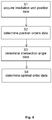
- Fig. 5
- illustrates a flow diagram representing basic steps of the disclosed method.
- a) a quantified offset in 6D (six degrees of freedom, namely three translational degrees of freedom and three rotational degrees of freedom); and
- b) the point in time the error was introduced.
- 1) Make a list of all viewing directions that have clear line of sight
- 2) Generate all possible combinations/orderings for these viewing directions
- 3) Compute for all orderings the sum of the (acute-angled) intersection angles of two consecutive viewing angles
- 4) Determine which ordering provides the maximum of this summation
- 5) In case there is more than one solution, take the one providing the smaller standard deviation
- 6) In case there is still more than one solution, take the solution that is easier for the operator (reduces gantry travelling time)
- A. A computer-implemented medical data processing method for determining a positional pattern of an irradiation unit for irradiating a patient with treatment radiation, the irradiation unit being part of an irradiation treatment device having an imaging device for generating a medical image of the patient, the method comprising executing, on at least one processor of at least one computer, steps of:
- a) acquiring (S1), at the at least one processor, irradiation unit position data describing irradiation unit positions of the irradiation unit for which the imaging device has a free viewing direction onto the position of the patient which is a free line of sight from the imaging device to the position of the patient;
- b) determining (S2), by the at least one processor and based on the irradiation unit position data, position orders data describing all possible orders of the irradiation unit positions for which the imaging device has a free viewing direction onto the position of the patient;
- c) determining (S3), by the at least one processor and based on the irradiation unit position data and the position orders data and per order described by the position orders data, intersection angle data describing a statistical quantity of the intersection angles between free viewing directions of the imaging unit for irradiation unit positions which are immediately subsequent in the order described by the position orders data;
- d) determining (S4), by the at least one processor and based on the intersection angle data and the position orders data, optimal order data describing an order of the irradiation unit positions for which the statistical value is optimal.
- B. The method according to embodiment A, wherein the irradiation unit position data is predetermined and has been generated on the basis of treatment plan data describing an irradiation treatment plan defining treatment positions which are relative positions between the irradiation treatment device and a treatment body part of the patient at which the treatment radiation shall be emitted.
- C. The method according to any one of embodiments A to B, wherein the imaging device comprises a single imaging unit or at least, for example exactly, two imaging units such as a range camera or an infrared-sensitive imaging device.
- D. The method according to embodiment C, wherein the single imaging unit or the at least two imaging units are x-ray devices or an infrared-sensitive imaging device.
- E. The method according to any one of embodiments A to D, wherein the free line of sight is not impeded by a part of the irradiation unit.
- F. The method according to any one of embodiments A to E, wherein the irradiation unit position data is predetermined and has been generated on the basis of device geometry data describing an operational geometry of the irradiation treatment device, for example the relative position between the irradiation unit and the viewing direction.
- G. The method according to any one of embodiments A to F, wherein the statistical quantity is a sum of the intersection angles, the average of the intersection angles, or the average field of view of the imaging unit between the viewing directions associated with the intersection angles.
- H. The method according to any one of embodiments A to G, wherein the optimal order is an order for which the statistical quantity is a maximum.
- I. The method according to any one of embodiments A to H, wherein, if more than one order of the irradiation unit position is associated with an optimum of the statistical quantity, the order of the irradiation unit positions associated with the smallest standard deviation is determined as the optimal order.
- J. The method according to embodiment I, wherein, if more than one order of the irradiation unit position is associated with a smallest standard deviation, the order of the irradiation unit positions associated with the smallest amount of time for moving the irradiation unit through the order of irradiation unit positions is determined as the optimal order.
- K. The method according to any one of embodiments A to J, wherein the intersection angles consist of obtuse angles and right angles or wherein the intersection angles consist of acute angles and right angles.
- L. The method according to any one of embodiments A to K, wherein the intersection angles between viewing directions define a field of view, for example a maximum field of view, of the imaging device between the pairwise subsequent irradiation unit positions.
- M.The method according to any one of embodiments A to L, wherein the imaging device comprises at least two imaging units and wherein the irradiation unit positions are positions of the irradiation unit for which the only one or all of the at least two imaging units have a free viewing direction.
- N. The method according to embodiment M, comprising:
- determining, based on the irradiation unit position data, stereo-imaging data describing irradiation unit positions for which all of the at least two imaging units have a free viewing direction,
- wherein the optimal order data is determined based on the stereo-imaging data, for example by preferring orders described by the position order data having a maximum of irradiation unit positions for which all of the at least two imaging units have a free viewing direction for determining the optimal order data.
- O. The method according to any one of embodiments M or N, comprising:
determining, based on the irradiation unit position data and by the at
least one processor, imaging unit control data describing a control signal for controlling only the at least one of the at least two imaging units which has a free viewing direction to take an image. - P. A computer-implemented medical data processing method for determining a positional pattern of an irradiation unit for irradiating a patient with treatment radiation, the irradiation unit being part of an irradiation treatment device having an imaging device having two imaging units for generating a medical image of the patient, the method comprising executing, on at least one processor of at least one computer, steps of:
- a) acquiring, at the at least one processor, irradiation unit position data describing irradiation unit positions of the irradiation unit for which the imaging device has a free viewing direction onto the position of the patient which is a free line of sight from at least one of the imaging units to the position of the patient;
- b) determining, by the at least one processor and based on the irradiation unit position data, irradiation unit control data describing control signals for controlling the irradiation unit to alternately attain irradiation unit positions described by the irradiation unit position data, wherein the free line of sight of each a different one of the two imaging units is impeded by at least part of the irradiation unit in two immediately subsequently attained irradiation unit positions.
- Q. A method for controlling the position of an irradiation unit of an irradiation treatment device, comprising executing, on at least one processor of at least one computer, steps of:
- executing the method according to any of embodiments A to P; and
- issuing, by the at least one processor and to the irradiation treatment
device and based on the optimal order data, control signal data for controlling the imaging unit to attain the imaging positions in the order described by the optimal order data.
- R. A computer program which, when running on at least one processor of at least one computer or when loaded into the memory of at least one computer, causes the at least one computer to perform the method according to any one of embodiments A to Q.
- S. A non-transitory computer-readable program storage medium on which the program according to embodiment R is stored.
- T. At least one computer, comprising at least one processor and a memory, wherein the program according to embodiment R is running on the at least one processor or is loaded into the memory, or wherein the at least one computer comprises the program storage medium according to the preceding embodiment.
- U. A system for determining a positional pattern of an irradiation unit for irradiating a patient with treatment radiation, the system comprising:
- a) the at least one computer according to embodiment T; and
- b) at least one electronic data storage device storing the irradiation unit position data and, as far as the program running on the at least one computer or loaded into the memory of the at least one computer causes the at least one computer to perform the method according to embodiment B, the treatment plan data,
wherein the at least one computer is operably coupled to the at least one electronic data storage device for acquiring, from the at least one electronic data storage device, the irradiation unit position data and, if the electronic data storage device stores the treatment plan data, the treatment plan data.
- V. A radiation treatment system, comprising:
- an irradiation treatment device comprising an irradiation unit and an imaging device; and
- the at least one computer of embodiment T or the system of embodiment U,
- wherein the at least one computer is operatively coupled to the irradiation treatment device for controlling the position of at least the irradiation unit on the basis of the optimal order data.
Claims (15)
- A computer-implemented medical data processing method for determining a positional pattern of an irradiation unit for irradiating a patient with treatment radiation, the irradiation unit being part of an irradiation treatment device having an imaging device for generating a medical image of the patient, the method comprising executing, on at least one processor of at least one computer, steps of:a) acquiring (S1), at the at least one processor, irradiation unit position data describing irradiation unit positions of the irradiation unit for which the imaging device has a free viewing direction onto the position of the patient which is a free line of sight from the imaging device to the position of the patient;b) determining (S2), by the at least one processor and based on the irradiation unit position data, position orders data describing all possible orders of the irradiation unit positions for which the imaging device has a free viewing direction onto the position of the patient;c) determining (S3), by the at least one processor and based on the irradiation unit position data and the position orders data and per order described by the position orders data, intersection angle data describing a statistical quantity of the intersection angles between free viewing directions of the imaging unit for irradiation unit positions which are immediately subsequent in the order described by the position orders data;d) determining (S4), by the at least one processor and based on the intersection angle data and the position orders data, optimal order data describing an order of the irradiation unit positions for which the statistical quantity is maximal.
- The method according to the preceding claim, wherein the irradiation unit position data is predetermined and has been generated on the basis of treatment plan data describing an irradiation treatment plan defining treatment positions which are relative positions between the irradiation treatment device and a treatment body part of the patient at which the treatment radiation shall be emitted.
- The method according to any one of the preceding claims, wherein the imaging device comprises a single imaging unit or at least, for example exactly, two imaging units such as a range camera or an infrared-sensitive imaging device.
- The method according to any one of the preceding claims, wherein the free line of sight is not impeded by a part of the irradiation unit.
- The method according to any one of the preceding claims, wherein the irradiation unit position data is predetermined and has been generated on the basis of device geometry data describing an operational geometry of the irradiation treatment device, for example the relative position between the irradiation unit and the viewing direction.
- The method according to any one of the preceding claims, wherein the statistical quantity is a sum of the intersection angles, the average of the intersection angles, or the average field of view of the imaging unit between the viewing directions associated with the intersection angles.
- The method according to any one of the preceding claims, wherein the imaging device comprises at least two imaging units and wherein the irradiation unit positions are positions of the irradiation unit for which the only one or all of the at least two imaging units have a free viewing direction.
- The method according to the preceding claim, comprising:determining, based on the irradiation unit position data, stereo-imaging data describing irradiation unit positions for which all of the at least two imaging units have a free viewing direction,wherein the optimal order data is determined based on the stereo-imaging data, for example by preferring orders described by the position order data having a maximum of irradiation unit positions for which all of the at least two imaging units have a free viewing direction for determining the optimal order data.
- The method according to any one of the two immediately preceding claims, comprising:
determining, based on the irradiation unit position data and by the at least one processor, imaging unit control data describing a control signal for controlling only the at least one of the at least two imaging units which has a free viewing direction to take an image. - A method for controlling the position of an irradiation unit of an irradiation treatment device, comprising executing, on at least one processor of at least one computer, steps of:executing the method according to any of the preceding claims; andissuing, by the at least one processor and to the irradiation treatment device and based on the optimal order data, control signal data for controlling the imaging unit to attain the imaging positions in the order described by the optimal order data.
- A computer program which, when running on at least one processor of at least one computer or when loaded into the memory of at least one computer, causes the at least one computer to perform the method according to any one of the preceding claims.
- A non-transitory computer-readable program storage medium on which the program according to the preceding claim is stored.
- At least one computer, comprising at least one processor and a memory, wherein the program according to claim 11 is running on the at least one processor or is loaded into the memory, or wherein the at least one computer comprises the program storage medium according to the preceding claim.
- A system for determining a positional pattern of an irradiation unit for irradiating a patient with treatment radiation, the system comprising:c) the at least one computer according to the preceding claim; andd) at least one electronic data storage device storing the irradiation unit position data and, as far as the program running on the at least one computer or loaded into the memory of the at least one computer causes the at least one computer to perform the method according to claim 2, the treatment plan data,
wherein the at least one computer is operably coupled to the at least one electronic data storage device for acquiring, from the at least one electronic data storage device, the irradiation unit position data and, if the electronic data storage device stores the treatment plan data, the treatment plan data. - A radiation treatment system, comprising:an irradiation treatment device comprising an irradiation unit and an imaging device; andthe at least one computer of claim 13 or the system of claim 14,wherein the at least one computer is operatively coupled to the irradiation treatment device for controlling the position of at least the irradiation unit on the basis of the optimal order data.
Applications Claiming Priority (3)
| Application Number | Priority Date | Filing Date | Title |
|---|---|---|---|
| EP2016052840 | 2016-02-10 | ||
| PCT/EP2017/052940 WO2017137527A1 (en) | 2016-02-10 | 2017-02-10 | Sorting the sequential arrangement of radiation treatment beams regarding well-distributed unobstructed lines of sight |
| EP17704255.3A EP3247457B1 (en) | 2016-02-10 | 2017-02-10 | Sorting the sequential arrangement of radiation treatment beams regarding well-distributed unobstructed lines of sight |
Related Parent Applications (2)
| Application Number | Title | Priority Date | Filing Date |
|---|---|---|---|
| EP17704255.3A Division EP3247457B1 (en) | 2016-02-10 | 2017-02-10 | Sorting the sequential arrangement of radiation treatment beams regarding well-distributed unobstructed lines of sight |
| EP17704255.3A Division-Into EP3247457B1 (en) | 2016-02-10 | 2017-02-10 | Sorting the sequential arrangement of radiation treatment beams regarding well-distributed unobstructed lines of sight |
Publications (2)
| Publication Number | Publication Date |
|---|---|
| EP3583983A1 true EP3583983A1 (en) | 2019-12-25 |
| EP3583983B1 EP3583983B1 (en) | 2021-04-14 |
Family
ID=58009835
Family Applications (2)
| Application Number | Title | Priority Date | Filing Date |
|---|---|---|---|
| EP19185906.5A Active EP3583983B1 (en) | 2016-02-10 | 2017-02-10 | Sorting the sequential arrangement of radiation treatment beams regarding well-distributed unobstructed lines of sight |
| EP17704255.3A Active EP3247457B1 (en) | 2016-02-10 | 2017-02-10 | Sorting the sequential arrangement of radiation treatment beams regarding well-distributed unobstructed lines of sight |
Family Applications After (1)
| Application Number | Title | Priority Date | Filing Date |
|---|---|---|---|
| EP17704255.3A Active EP3247457B1 (en) | 2016-02-10 | 2017-02-10 | Sorting the sequential arrangement of radiation treatment beams regarding well-distributed unobstructed lines of sight |
Country Status (3)
| Country | Link |
|---|---|
| US (2) | US10780297B2 (en) |
| EP (2) | EP3583983B1 (en) |
| WO (1) | WO2017137527A1 (en) |
Families Citing this family (7)
| Publication number | Priority date | Publication date | Assignee | Title |
|---|---|---|---|---|
| US10342996B2 (en) | 2016-08-29 | 2019-07-09 | Accuray Incorporated | Online angle selection in rotational imaging and tracking systems |
| US10532224B2 (en) * | 2016-08-29 | 2020-01-14 | Accuray Incorporated | Offline angle selection in rotational imaging and tracking systems |
| WO2019238220A1 (en) * | 2018-06-12 | 2019-12-19 | Brainlab Ag | Image acquisition based on treatment device position |
| CN110379480B (en) * | 2019-07-18 | 2022-09-16 | 合肥工业大学 | Rehabilitation training evaluation method and system |
| WO2021028022A1 (en) | 2019-08-13 | 2021-02-18 | Brainlab Ag | Triggering of x-ray-images based on surface measurements |
| TWI793390B (en) * | 2019-12-25 | 2023-02-21 | 財團法人工業技術研究院 | Method, processing device, and display system for information display |
| US11445594B1 (en) | 2021-05-21 | 2022-09-13 | Varian Medical Systems, Inc. | Method and system for remote monitoring of proton beam emitting and delivery system |
Citations (3)
| Publication number | Priority date | Publication date | Assignee | Title |
|---|---|---|---|---|
| US20070003007A1 (en) * | 2005-06-29 | 2007-01-04 | Carrano Aaron W | Imaging geometry |
| EP2159725A1 (en) * | 2008-08-26 | 2010-03-03 | Siemens Medical Solutions USA, Inc. | Patient setup error evaluation and error minimizing setup correction in association with radiotherapy treatment |
| US20110080990A1 (en) * | 2009-10-02 | 2011-04-07 | Varian Medical Systems, Inc. | Systems and methods for obtaining reconstructed images during a treatment session |
Family Cites Families (4)
| Publication number | Priority date | Publication date | Assignee | Title |
|---|---|---|---|---|
| US7046762B2 (en) * | 1999-11-05 | 2006-05-16 | Georgia Tech Research Corporation | Systems and methods for global optimization of treatment planning for external beam radiation therapy |
| US9616247B2 (en) * | 2007-03-30 | 2017-04-11 | Koninklijke Philips N.V. | Treatment plan evaluation in radiotherapy by stochastic analysis of delineation uncertainty |
| US8086004B2 (en) | 2008-01-15 | 2011-12-27 | Accuray Incorporated | Use of a single X-ray image for quality assurance of tracking |
| US20170216632A1 (en) * | 2010-04-16 | 2017-08-03 | W. Davis Lee | Dispersive force corrected gantry based radiation treatment apparatus and method of use thereof |
-
2017
- 2017-02-10 US US15/564,600 patent/US10780297B2/en active Active
- 2017-02-10 WO PCT/EP2017/052940 patent/WO2017137527A1/en not_active Ceased
- 2017-02-10 EP EP19185906.5A patent/EP3583983B1/en active Active
- 2017-02-10 EP EP17704255.3A patent/EP3247457B1/en active Active
-
2020
- 2020-08-12 US US16/991,176 patent/US11730978B2/en active Active
Patent Citations (3)
| Publication number | Priority date | Publication date | Assignee | Title |
|---|---|---|---|---|
| US20070003007A1 (en) * | 2005-06-29 | 2007-01-04 | Carrano Aaron W | Imaging geometry |
| EP2159725A1 (en) * | 2008-08-26 | 2010-03-03 | Siemens Medical Solutions USA, Inc. | Patient setup error evaluation and error minimizing setup correction in association with radiotherapy treatment |
| US20110080990A1 (en) * | 2009-10-02 | 2011-04-07 | Varian Medical Systems, Inc. | Systems and methods for obtaining reconstructed images during a treatment session |
Also Published As
| Publication number | Publication date |
|---|---|
| WO2017137527A1 (en) | 2017-08-17 |
| US11730978B2 (en) | 2023-08-22 |
| EP3247457A1 (en) | 2017-11-29 |
| US10780297B2 (en) | 2020-09-22 |
| EP3583983B1 (en) | 2021-04-14 |
| EP3247457B1 (en) | 2019-10-23 |
| US20180093110A1 (en) | 2018-04-05 |
| US20210060359A1 (en) | 2021-03-04 |
Similar Documents
| Publication | Publication Date | Title |
|---|---|---|
| US20230008051A1 (en) | Utilization of a transportable ct-scanner for radiotherapy procedures | |
| US11730978B2 (en) | Sorting the sequential arrangement of radiation treatment beams regarding well-distributed unobstructed lines of sight | |
| US10543381B2 (en) | System for monitoring the position of a patient receiving 4pi radiation therapy | |
| US11669982B2 (en) | Soft tissue stereo-tracking | |
| US10448905B2 (en) | Frameless pre-positioning for radiosurgery | |
| US10926106B2 (en) | Patient pre-positioning in frameless cranial radiosurgery using thermal imaging | |
| EP3622479B1 (en) | Partitioning a medical image | |
| US20250256128A1 (en) | Determining physically correct digitally reconstructed radiographs | |
| US20210145372A1 (en) | Image acquisition based on treatment device position |
Legal Events
| Date | Code | Title | Description |
|---|---|---|---|
| STAA | Information on the status of an ep patent application or granted ep patent |
Free format text: STATUS: EXAMINATION IS IN PROGRESS |
|
| PUAI | Public reference made under article 153(3) epc to a published international application that has entered the european phase |
Free format text: ORIGINAL CODE: 0009012 |
|
| 17P | Request for examination filed |
Effective date: 20190712 |
|
| AC | Divisional application: reference to earlier application |
Ref document number: 3247457 Country of ref document: EP Kind code of ref document: P |
|
| AK | Designated contracting states |
Kind code of ref document: A1 Designated state(s): AL AT BE BG CH CY CZ DE DK EE ES FI FR GB GR HR HU IE IS IT LI LT LU LV MC MK MT NL NO PL PT RO RS SE SI SK SM TR |
|
| GRAP | Despatch of communication of intention to grant a patent |
Free format text: ORIGINAL CODE: EPIDOSNIGR1 |
|
| STAA | Information on the status of an ep patent application or granted ep patent |
Free format text: STATUS: GRANT OF PATENT IS INTENDED |
|
| INTG | Intention to grant announced |
Effective date: 20200915 |
|
| GRAS | Grant fee paid |
Free format text: ORIGINAL CODE: EPIDOSNIGR3 |
|
| GRAJ | Information related to disapproval of communication of intention to grant by the applicant or resumption of examination proceedings by the epo deleted |
Free format text: ORIGINAL CODE: EPIDOSDIGR1 |
|
| GRAL | Information related to payment of fee for publishing/printing deleted |
Free format text: ORIGINAL CODE: EPIDOSDIGR3 |
|
| STAA | Information on the status of an ep patent application or granted ep patent |
Free format text: STATUS: EXAMINATION IS IN PROGRESS |
|
| INTC | Intention to grant announced (deleted) | ||
| GRAP | Despatch of communication of intention to grant a patent |
Free format text: ORIGINAL CODE: EPIDOSNIGR1 |
|
| GRAJ | Information related to disapproval of communication of intention to grant by the applicant or resumption of examination proceedings by the epo deleted |
Free format text: ORIGINAL CODE: EPIDOSDIGR1 |
|
| GRAP | Despatch of communication of intention to grant a patent |
Free format text: ORIGINAL CODE: EPIDOSNIGR1 |
|
| STAA | Information on the status of an ep patent application or granted ep patent |
Free format text: STATUS: GRANT OF PATENT IS INTENDED |
|
| GRAA | (expected) grant |
Free format text: ORIGINAL CODE: 0009210 |
|
| STAA | Information on the status of an ep patent application or granted ep patent |
Free format text: STATUS: THE PATENT HAS BEEN GRANTED |
|
| INTG | Intention to grant announced |
Effective date: 20210224 |
|
| AC | Divisional application: reference to earlier application |
Ref document number: 3247457 Country of ref document: EP Kind code of ref document: P |
|
| AK | Designated contracting states |
Kind code of ref document: B1 Designated state(s): AL AT BE BG CH CY CZ DE DK EE ES FI FR GB GR HR HU IE IS IT LI LT LU LV MC MK MT NL NO PL PT RO RS SE SI SK SM TR |
|
| REG | Reference to a national code |
Ref country code: GB Ref legal event code: FG4D |
|
| REG | Reference to a national code |
Ref country code: CH Ref legal event code: EP |
|
| REG | Reference to a national code |
Ref country code: CH Ref legal event code: NV Representative=s name: RIEDERER HASLER AND PARTNER PATENTANWAELTE AG, LI |
|
| REG | Reference to a national code |
Ref country code: DE Ref legal event code: R096 Ref document number: 602017036937 Country of ref document: DE |
|
| REG | Reference to a national code |
Ref country code: SE Ref legal event code: TRGR |
|
| REG | Reference to a national code |
Ref country code: IE Ref legal event code: FG4D |
|
| REG | Reference to a national code |
Ref country code: AT Ref legal event code: REF Ref document number: 1381760 Country of ref document: AT Kind code of ref document: T Effective date: 20210515 |
|
| REG | Reference to a national code |
Ref country code: LT Ref legal event code: MG9D |
|
| REG | Reference to a national code |
Ref country code: AT Ref legal event code: MK05 Ref document number: 1381760 Country of ref document: AT Kind code of ref document: T Effective date: 20210414 |
|
| REG | Reference to a national code |
Ref country code: NL Ref legal event code: MP Effective date: 20210414 |
|
| PG25 | Lapsed in a contracting state [announced via postgrant information from national office to epo] |
Ref country code: NL Free format text: LAPSE BECAUSE OF FAILURE TO SUBMIT A TRANSLATION OF THE DESCRIPTION OR TO PAY THE FEE WITHIN THE PRESCRIBED TIME-LIMIT Effective date: 20210414 Ref country code: BG Free format text: LAPSE BECAUSE OF FAILURE TO SUBMIT A TRANSLATION OF THE DESCRIPTION OR TO PAY THE FEE WITHIN THE PRESCRIBED TIME-LIMIT Effective date: 20210714 Ref country code: AT Free format text: LAPSE BECAUSE OF FAILURE TO SUBMIT A TRANSLATION OF THE DESCRIPTION OR TO PAY THE FEE WITHIN THE PRESCRIBED TIME-LIMIT Effective date: 20210414 Ref country code: FI Free format text: LAPSE BECAUSE OF FAILURE TO SUBMIT A TRANSLATION OF THE DESCRIPTION OR TO PAY THE FEE WITHIN THE PRESCRIBED TIME-LIMIT Effective date: 20210414 Ref country code: LT Free format text: LAPSE BECAUSE OF FAILURE TO SUBMIT A TRANSLATION OF THE DESCRIPTION OR TO PAY THE FEE WITHIN THE PRESCRIBED TIME-LIMIT Effective date: 20210414 Ref country code: HR Free format text: LAPSE BECAUSE OF FAILURE TO SUBMIT A TRANSLATION OF THE DESCRIPTION OR TO PAY THE FEE WITHIN THE PRESCRIBED TIME-LIMIT Effective date: 20210414 |
|
| PG25 | Lapsed in a contracting state [announced via postgrant information from national office to epo] |
Ref country code: RS Free format text: LAPSE BECAUSE OF FAILURE TO SUBMIT A TRANSLATION OF THE DESCRIPTION OR TO PAY THE FEE WITHIN THE PRESCRIBED TIME-LIMIT Effective date: 20210414 Ref country code: PT Free format text: LAPSE BECAUSE OF FAILURE TO SUBMIT A TRANSLATION OF THE DESCRIPTION OR TO PAY THE FEE WITHIN THE PRESCRIBED TIME-LIMIT Effective date: 20210816 Ref country code: PL Free format text: LAPSE BECAUSE OF FAILURE TO SUBMIT A TRANSLATION OF THE DESCRIPTION OR TO PAY THE FEE WITHIN THE PRESCRIBED TIME-LIMIT Effective date: 20210414 Ref country code: NO Free format text: LAPSE BECAUSE OF FAILURE TO SUBMIT A TRANSLATION OF THE DESCRIPTION OR TO PAY THE FEE WITHIN THE PRESCRIBED TIME-LIMIT Effective date: 20210714 Ref country code: LV Free format text: LAPSE BECAUSE OF FAILURE TO SUBMIT A TRANSLATION OF THE DESCRIPTION OR TO PAY THE FEE WITHIN THE PRESCRIBED TIME-LIMIT Effective date: 20210414 Ref country code: IS Free format text: LAPSE BECAUSE OF FAILURE TO SUBMIT A TRANSLATION OF THE DESCRIPTION OR TO PAY THE FEE WITHIN THE PRESCRIBED TIME-LIMIT Effective date: 20210814 Ref country code: GR Free format text: LAPSE BECAUSE OF FAILURE TO SUBMIT A TRANSLATION OF THE DESCRIPTION OR TO PAY THE FEE WITHIN THE PRESCRIBED TIME-LIMIT Effective date: 20210715 |
|
| REG | Reference to a national code |
Ref country code: DE Ref legal event code: R097 Ref document number: 602017036937 Country of ref document: DE |
|
| PG25 | Lapsed in a contracting state [announced via postgrant information from national office to epo] |
Ref country code: CZ Free format text: LAPSE BECAUSE OF FAILURE TO SUBMIT A TRANSLATION OF THE DESCRIPTION OR TO PAY THE FEE WITHIN THE PRESCRIBED TIME-LIMIT Effective date: 20210414 Ref country code: DK Free format text: LAPSE BECAUSE OF FAILURE TO SUBMIT A TRANSLATION OF THE DESCRIPTION OR TO PAY THE FEE WITHIN THE PRESCRIBED TIME-LIMIT Effective date: 20210414 Ref country code: SM Free format text: LAPSE BECAUSE OF FAILURE TO SUBMIT A TRANSLATION OF THE DESCRIPTION OR TO PAY THE FEE WITHIN THE PRESCRIBED TIME-LIMIT Effective date: 20210414 Ref country code: RO Free format text: LAPSE BECAUSE OF FAILURE TO SUBMIT A TRANSLATION OF THE DESCRIPTION OR TO PAY THE FEE WITHIN THE PRESCRIBED TIME-LIMIT Effective date: 20210414 Ref country code: EE Free format text: LAPSE BECAUSE OF FAILURE TO SUBMIT A TRANSLATION OF THE DESCRIPTION OR TO PAY THE FEE WITHIN THE PRESCRIBED TIME-LIMIT Effective date: 20210414 Ref country code: ES Free format text: LAPSE BECAUSE OF FAILURE TO SUBMIT A TRANSLATION OF THE DESCRIPTION OR TO PAY THE FEE WITHIN THE PRESCRIBED TIME-LIMIT Effective date: 20210414 Ref country code: SK Free format text: LAPSE BECAUSE OF FAILURE TO SUBMIT A TRANSLATION OF THE DESCRIPTION OR TO PAY THE FEE WITHIN THE PRESCRIBED TIME-LIMIT Effective date: 20210414 |
|
| PLBE | No opposition filed within time limit |
Free format text: ORIGINAL CODE: 0009261 |
|
| STAA | Information on the status of an ep patent application or granted ep patent |
Free format text: STATUS: NO OPPOSITION FILED WITHIN TIME LIMIT |
|
| 26N | No opposition filed |
Effective date: 20220117 |
|
| PG25 | Lapsed in a contracting state [announced via postgrant information from national office to epo] |
Ref country code: IS Free format text: LAPSE BECAUSE OF FAILURE TO SUBMIT A TRANSLATION OF THE DESCRIPTION OR TO PAY THE FEE WITHIN THE PRESCRIBED TIME-LIMIT Effective date: 20210814 Ref country code: AL Free format text: LAPSE BECAUSE OF FAILURE TO SUBMIT A TRANSLATION OF THE DESCRIPTION OR TO PAY THE FEE WITHIN THE PRESCRIBED TIME-LIMIT Effective date: 20210414 |
|
| PG25 | Lapsed in a contracting state [announced via postgrant information from national office to epo] |
Ref country code: IT Free format text: LAPSE BECAUSE OF FAILURE TO SUBMIT A TRANSLATION OF THE DESCRIPTION OR TO PAY THE FEE WITHIN THE PRESCRIBED TIME-LIMIT Effective date: 20210414 |
|
| PG25 | Lapsed in a contracting state [announced via postgrant information from national office to epo] |
Ref country code: MC Free format text: LAPSE BECAUSE OF FAILURE TO SUBMIT A TRANSLATION OF THE DESCRIPTION OR TO PAY THE FEE WITHIN THE PRESCRIBED TIME-LIMIT Effective date: 20210414 |
|
| REG | Reference to a national code |
Ref country code: BE Ref legal event code: MM Effective date: 20220228 |
|
| GBPC | Gb: european patent ceased through non-payment of renewal fee |
Effective date: 20220210 |
|
| PG25 | Lapsed in a contracting state [announced via postgrant information from national office to epo] |
Ref country code: LU Free format text: LAPSE BECAUSE OF NON-PAYMENT OF DUE FEES Effective date: 20220210 |
|
| PG25 | Lapsed in a contracting state [announced via postgrant information from national office to epo] |
Ref country code: FR Free format text: LAPSE BECAUSE OF NON-PAYMENT OF DUE FEES Effective date: 20220228 |
|
| PG25 | Lapsed in a contracting state [announced via postgrant information from national office to epo] |
Ref country code: IE Free format text: LAPSE BECAUSE OF NON-PAYMENT OF DUE FEES Effective date: 20220210 Ref country code: GB Free format text: LAPSE BECAUSE OF NON-PAYMENT OF DUE FEES Effective date: 20220210 |
|
| PG25 | Lapsed in a contracting state [announced via postgrant information from national office to epo] |
Ref country code: BE Free format text: LAPSE BECAUSE OF NON-PAYMENT OF DUE FEES Effective date: 20220228 |
|
| P01 | Opt-out of the competence of the unified patent court (upc) registered |
Effective date: 20230512 |
|
| PG25 | Lapsed in a contracting state [announced via postgrant information from national office to epo] |
Ref country code: MK Free format text: LAPSE BECAUSE OF FAILURE TO SUBMIT A TRANSLATION OF THE DESCRIPTION OR TO PAY THE FEE WITHIN THE PRESCRIBED TIME-LIMIT Effective date: 20210414 Ref country code: CY Free format text: LAPSE BECAUSE OF FAILURE TO SUBMIT A TRANSLATION OF THE DESCRIPTION OR TO PAY THE FEE WITHIN THE PRESCRIBED TIME-LIMIT Effective date: 20210414 |
|
| PG25 | Lapsed in a contracting state [announced via postgrant information from national office to epo] |
Ref country code: HU Free format text: LAPSE BECAUSE OF FAILURE TO SUBMIT A TRANSLATION OF THE DESCRIPTION OR TO PAY THE FEE WITHIN THE PRESCRIBED TIME-LIMIT; INVALID AB INITIO Effective date: 20170210 |
|
| PG25 | Lapsed in a contracting state [announced via postgrant information from national office to epo] |
Ref country code: MT Free format text: LAPSE BECAUSE OF FAILURE TO SUBMIT A TRANSLATION OF THE DESCRIPTION OR TO PAY THE FEE WITHIN THE PRESCRIBED TIME-LIMIT Effective date: 20210414 |
|
| REG | Reference to a national code |
Ref country code: DE Ref legal event code: R081 Ref document number: 602017036937 Country of ref document: DE Owner name: BRAINLAB SE, DE Free format text: FORMER OWNER: BRAINLAB AG, 81829 MUENCHEN, DE |
|
| PG25 | Lapsed in a contracting state [announced via postgrant information from national office to epo] |
Ref country code: TR Free format text: LAPSE BECAUSE OF FAILURE TO SUBMIT A TRANSLATION OF THE DESCRIPTION OR TO PAY THE FEE WITHIN THE PRESCRIBED TIME-LIMIT Effective date: 20210414 |
|
| REG | Reference to a national code |
Ref country code: CH Ref legal event code: R18 Free format text: ST27 STATUS EVENT CODE: U-0-0-R10-R18 (AS PROVIDED BY THE NATIONAL OFFICE) Effective date: 20260129 |
|
| REG | Reference to a national code |
Ref country code: CH Ref legal event code: U11 Free format text: ST27 STATUS EVENT CODE: U-0-0-U10-U11 (AS PROVIDED BY THE NATIONAL OFFICE) Effective date: 20260301 |
|
| PGFP | Annual fee paid to national office [announced via postgrant information from national office to epo] |
Ref country code: SE Payment date: 20260218 Year of fee payment: 10 |
|
| PGFP | Annual fee paid to national office [announced via postgrant information from national office to epo] |
Ref country code: DE Payment date: 20260218 Year of fee payment: 10 |
|
| PGFP | Annual fee paid to national office [announced via postgrant information from national office to epo] |
Ref country code: CH Payment date: 20260301 Year of fee payment: 10 |