EP3583957A1 - Gasifying device for sterilization agent and method for cleaning gasifying device for sterilization agent - Google Patents
Gasifying device for sterilization agent and method for cleaning gasifying device for sterilization agent Download PDFInfo
- Publication number
- EP3583957A1 EP3583957A1 EP18753557.0A EP18753557A EP3583957A1 EP 3583957 A1 EP3583957 A1 EP 3583957A1 EP 18753557 A EP18753557 A EP 18753557A EP 3583957 A1 EP3583957 A1 EP 3583957A1
- Authority
- EP
- European Patent Office
- Prior art keywords
- sterilizer
- cleaning liquid
- heating surface
- gasifier
- cleaning
- Prior art date
- Legal status (The legal status is an assumption and is not a legal conclusion. Google has not performed a legal analysis and makes no representation as to the accuracy of the status listed.)
- Granted
Links
Images




Classifications
-
- A—HUMAN NECESSITIES
- A61—MEDICAL OR VETERINARY SCIENCE; HYGIENE
- A61L—METHODS OR APPARATUS FOR STERILISING MATERIALS OR OBJECTS IN GENERAL; DISINFECTION, STERILISATION OR DEODORISATION OF AIR; CHEMICAL ASPECTS OF BANDAGES, DRESSINGS, ABSORBENT PADS OR SURGICAL ARTICLES; MATERIALS FOR BANDAGES, DRESSINGS, ABSORBENT PADS OR SURGICAL ARTICLES
- A61L2/00—Disinfection or sterilisation of materials or objects, in general; Accessories therefor
- A61L2/16—Disinfection or sterilisation of materials or objects, in general; Accessories therefor using chemical substances
- A61L2/18—Liquid substances
- A61L2/186—Peroxide solutions
-
- A—HUMAN NECESSITIES
- A61—MEDICAL OR VETERINARY SCIENCE; HYGIENE
- A61L—METHODS OR APPARATUS FOR STERILISING MATERIALS OR OBJECTS IN GENERAL; DISINFECTION, STERILISATION OR DEODORISATION OF AIR; CHEMICAL ASPECTS OF BANDAGES, DRESSINGS, ABSORBENT PADS OR SURGICAL ARTICLES; MATERIALS FOR BANDAGES, DRESSINGS, ABSORBENT PADS OR SURGICAL ARTICLES
- A61L2/00—Disinfection or sterilisation of materials or objects, in general; Accessories therefor
- A61L2/16—Disinfection or sterilisation of materials or objects, in general; Accessories therefor using chemical substances
- A61L2/20—Gaseous substances, e.g. vapours
- A61L2/208—Hydrogen peroxide
-
- B—PERFORMING OPERATIONS; TRANSPORTING
- B08—CLEANING
- B08B—CLEANING IN GENERAL; PREVENTION OF FOULING IN GENERAL
- B08B3/00—Cleaning by methods involving the use or presence of liquid or steam
- B08B3/02—Cleaning by the force of jets or sprays
-
- A—HUMAN NECESSITIES
- A61—MEDICAL OR VETERINARY SCIENCE; HYGIENE
- A61L—METHODS OR APPARATUS FOR STERILISING MATERIALS OR OBJECTS IN GENERAL; DISINFECTION, STERILISATION OR DEODORISATION OF AIR; CHEMICAL ASPECTS OF BANDAGES, DRESSINGS, ABSORBENT PADS OR SURGICAL ARTICLES; MATERIALS FOR BANDAGES, DRESSINGS, ABSORBENT PADS OR SURGICAL ARTICLES
- A61L2/00—Disinfection or sterilisation of materials or objects, in general; Accessories therefor
- A61L2/16—Disinfection or sterilisation of materials or objects, in general; Accessories therefor using chemical substances
- A61L2/20—Gaseous substances, e.g. vapours
-
- B—PERFORMING OPERATIONS; TRANSPORTING
- B01—PHYSICAL OR CHEMICAL PROCESSES OR APPARATUS IN GENERAL
- B01D—SEPARATION
- B01D1/00—Evaporating
- B01D1/14—Evaporating with heated gases or vapours or liquids in contact with the liquid
-
- B—PERFORMING OPERATIONS; TRANSPORTING
- B01—PHYSICAL OR CHEMICAL PROCESSES OR APPARATUS IN GENERAL
- B01D—SEPARATION
- B01D1/00—Evaporating
- B01D1/16—Evaporating by spraying
-
- B—PERFORMING OPERATIONS; TRANSPORTING
- B01—PHYSICAL OR CHEMICAL PROCESSES OR APPARATUS IN GENERAL
- B01D—SEPARATION
- B01D1/00—Evaporating
- B01D1/22—Evaporating by bringing a thin layer of the liquid into contact with a heated surface
-
- B—PERFORMING OPERATIONS; TRANSPORTING
- B08—CLEANING
- B08B—CLEANING IN GENERAL; PREVENTION OF FOULING IN GENERAL
- B08B5/00—Cleaning by methods involving the use of air flow or gas flow
- B08B5/02—Cleaning by the force of jets, e.g. blowing-out cavities
-
- B—PERFORMING OPERATIONS; TRANSPORTING
- B08—CLEANING
- B08B—CLEANING IN GENERAL; PREVENTION OF FOULING IN GENERAL
- B08B9/00—Cleaning hollow articles by methods or apparatus specially adapted thereto
-
- B—PERFORMING OPERATIONS; TRANSPORTING
- B65—CONVEYING; PACKING; STORING; HANDLING THIN OR FILAMENTARY MATERIAL
- B65B—MACHINES, APPARATUS OR DEVICES FOR, OR METHODS OF, PACKAGING ARTICLES OR MATERIALS; UNPACKING
- B65B55/00—Preserving, protecting or purifying packages or package contents in association with packaging
- B65B55/02—Sterilising, e.g. of complete packages
- B65B55/04—Sterilising wrappers or receptacles prior to, or during, packaging
- B65B55/10—Sterilising wrappers or receptacles prior to, or during, packaging by liquids or gases
-
- A—HUMAN NECESSITIES
- A01—AGRICULTURE; FORESTRY; ANIMAL HUSBANDRY; HUNTING; TRAPPING; FISHING
- A01N—PRESERVATION OF BODIES OF HUMANS OR ANIMALS OR PLANTS OR PARTS THEREOF; BIOCIDES, e.g. AS DISINFECTANTS, AS PESTICIDES OR AS HERBICIDES; PEST REPELLANTS OR ATTRACTANTS; PLANT GROWTH REGULATORS
- A01N59/00—Biocides, pest repellants or attractants, or plant growth regulators containing elements or inorganic compounds
-
- A—HUMAN NECESSITIES
- A23—FOODS OR FOODSTUFFS; TREATMENT THEREOF, NOT COVERED BY OTHER CLASSES
- A23B—PRESERVATION OF FOODS, FOODSTUFFS OR NON-ALCOHOLIC BEVERAGES; CHEMICAL RIPENING OF FRUIT OR VEGETABLES
- A23B2/00—Preservation of foods or foodstuffs, in general
- A23B2/40—Preservation of foods or foodstuffs, in general by heating loose unpacked materials
- A23B2/48—Preservation of foods or foodstuffs, in general by heating loose unpacked materials with the materials in spray form
-
- A—HUMAN NECESSITIES
- A23—FOODS OR FOODSTUFFS; TREATMENT THEREOF, NOT COVERED BY OTHER CLASSES
- A23B—PRESERVATION OF FOODS, FOODSTUFFS OR NON-ALCOHOLIC BEVERAGES; CHEMICAL RIPENING OF FRUIT OR VEGETABLES
- A23B2/00—Preservation of foods or foodstuffs, in general
- A23B2/70—Preservation of foods or foodstuffs, in general by treatment with chemicals
- A23B2/704—Preservation of foods or foodstuffs, in general by treatment with chemicals in the form of gases, e.g. fumigation; Compositions or apparatus therefor
- A23B2/721—Preservation of foods or foodstuffs, in general by treatment with chemicals in the form of gases, e.g. fumigation; Compositions or apparatus therefor in a controlled atmosphere comprising other gases in addition to CO2, N2, O2 or H2O
-
- A—HUMAN NECESSITIES
- A61—MEDICAL OR VETERINARY SCIENCE; HYGIENE
- A61L—METHODS OR APPARATUS FOR STERILISING MATERIALS OR OBJECTS IN GENERAL; DISINFECTION, STERILISATION OR DEODORISATION OF AIR; CHEMICAL ASPECTS OF BANDAGES, DRESSINGS, ABSORBENT PADS OR SURGICAL ARTICLES; MATERIALS FOR BANDAGES, DRESSINGS, ABSORBENT PADS OR SURGICAL ARTICLES
- A61L2103/00—Materials or objects being the target of disinfection or sterilisation
- A61L2103/23—Containers other than laboratory or medical, e.g. bottles or mail
-
- B—PERFORMING OPERATIONS; TRANSPORTING
- B08—CLEANING
- B08B—CLEANING IN GENERAL; PREVENTION OF FOULING IN GENERAL
- B08B2203/00—Details of cleaning machines or methods involving the use or presence of liquid or steam
- B08B2203/007—Heating the liquid
-
- B—PERFORMING OPERATIONS; TRANSPORTING
- B08—CLEANING
- B08B—CLEANING IN GENERAL; PREVENTION OF FOULING IN GENERAL
- B08B2203/00—Details of cleaning machines or methods involving the use or presence of liquid or steam
- B08B2203/02—Details of machines or methods for cleaning by the force of jets or sprays
- B08B2203/0217—Use of a detergent in high pressure cleaners; arrangements for supplying the same
-
- B—PERFORMING OPERATIONS; TRANSPORTING
- B65—CONVEYING; PACKING; STORING; HANDLING THIN OR FILAMENTARY MATERIAL
- B65B—MACHINES, APPARATUS OR DEVICES FOR, OR METHODS OF, PACKAGING ARTICLES OR MATERIALS; UNPACKING
- B65B2210/00—Specific aspects of the packaging machine
- B65B2210/06—Sterilising or cleaning machinery or conduits
Definitions
- the aseptic filling and packaging machine handles various types of packaging used as containers as described above, and sterilization processes differ according to the packaging.
- packaging are irradiated with ultraviolet rays or electron beams, but a method of sterilizing surfaces of the packaging with a sterilizer is generally used.
- packaging which are flat before molding such as creamers or brick cartons are sterilized by being immersed in the sterilizer, but there is also a method for spraying the sterilizer.
- Packaging that are flat and do not have a problem to a drying temperature at a relatively high temperature after immersion are sterilized by immersion, but molded containers such as cups or bottles or other packaging such as films that are stretched by drying at high temperatures are sterilized by spraying of the sterilizer.
- a hydrogen peroxide solution is mainly used as the sterilizer, and any trace amount of heavy metal contained in the hydrogen peroxide solution causes decomposition of hydrogen peroxide.
- sodium pyrophosphate or orthophosphoric acid which has been proven to be safe and effective, is added as a stabilizer to the hydrogen peroxide solution used for sterilization in the aseptic filling and packaging machine (Patent Literature 5).
- the hydrogen peroxide solution is gasified, such a stabilizer can be deposited and accumulated on the surface of the heating element, thereby reducing the efficiency of the gasification of the hydrogen peroxide solution or blocking the nozzle that blasts the gas of the hydrogen peroxide solution to the object to be sterilized.
- a gasified hydrogen peroxide solution is often used.
- the method for gasifying a hydrogen peroxide solution is achieved by bringing the hydrogen peroxide solution into contact with the heating element.
- the stabilizer which is added to the hydrogen peroxide solution can be deposited and accumulated on the heating element as the hydrogen peroxide solution is gasified.
- the accumulated stabilizer impedes heat conduction to the outermost surface of the heating element, and reduces the efficiency of gasification of the hydrogen peroxide solution.
- the gasifier for a sterilizer needs to be regularly disassembled and cleaned, which reduces productivity.
- the cleaning device includes a tank that stores the cleaning liquid, a pump that supplies the cleaning liquid to the cleaning liquid blasting device, and an air supplying device that supplies air to the cleaning liquid blasting device.
- a cleaning liquid circulating device having a discharge port closing cup that closes a cleaning liquid discharge port from which the cleaning liquid is discharged, and recovers the cleaning liquid which is discharged, and a circulation pump that supplies the recovered cleaning liquid to the cleaning device is provided.
- the cleaning method of a gasifier for a sterilizer it is preferable that after the cleaning liquid is blasted to the heating surface, air is blasted to the heating surface.
- FIG. 1 illustrates a first embodiment of a gasifier 1 for a sterilizer according to the present invention.
- the gasifier 1 for a sterilizer includes a sterilizer supplying portion 2, a sterilizer evaporating portion 3, and a heated air supplying device 12.
- the sterilizer supplying portion 2 includes a tank 5 that stores a sterilizer 4, a dropper 7 that drips the sterilizer 4 into the sterilizer evaporating portion 3, and a pump 6 that feeds the sterilizer 4 to the dropper 7.
- the sterilizer evaporating portion 3 includes a heating body 8 that gasifies the sterilizer 4 dripped into the sterilizer evaporating portion 3.
- the heated air supplying device 12 includes a blower 10 that feeds air, and a heating device 11 that heats the air fed by the blower 10.
- the sterilizer 4 may contain one or more of alcohols such as methyl alcohol, ethyl alcohol, isopropyl alcohol, normal propyl alcohol and butyl alcohol, ketones such as acetone, methyl ethyl ketone and acetylacetone, and glycol ethers, for example.
- alcohols such as methyl alcohol, ethyl alcohol, isopropyl alcohol, normal propyl alcohol and butyl alcohol
- ketones such as acetone, methyl ethyl ketone and acetylacetone
- glycol ethers for example.
- the sterilizer 4 may further contain an additive agent such as a compound having a sterilizing effect such as peracetic acid, acetic acid, a chlorine compound or ozone, a cationic surface active agent and a non-ionic surface active agent.
- an additive agent such as a compound having a sterilizing effect such as peracetic acid, acetic acid, a chlorine compound or ozone, a cationic surface active agent and a non-ionic surface active agent.
- the temperature of the heating surface 9 of the heating body 8 that gasifies the sterilizer 4 is set at 130°C to 450°C. If the temperature is lower than 130°C, gasification is difficult, whereas if the temperature is higher than 450°C, hydrogen peroxide is decomposed.
- the heating surface 9 of the heating body 8 may be a planar surface, and horizontal or provided with an inclination, or may be a curved surface such as a concave or convex surface.
- the heating surface 9 of the heating body 8 can have any shape as far as the sterilizer 4 can come into contact with the heating surface 9 of the heating body 8 and be gasified.
- the heating body 8 can have any size and thickness. When the volume of the heating body 8 is large, the heat capacity is large, which is advantageous for gasification of the sterilizer 4, but the gasifier 1 for a sterilizer becomes excessively large.
- the surface of the heating surface 9 preferably has an arithmetic mean roughness (Ra) of 1.0 ⁇ m or less and a ten-point mean roughness (Rz) of 2.0 ⁇ m or less. If Ra is greater than 1.0 ⁇ m, or Rz is greater than 2.0 ⁇ m, the concentration of hydrogen peroxide in the gas of the sterilizer decreases. It is presumed that this is because if the surface area is large, the sterilizer is excessively heated when the sterilizer comes into contact with the heating surface 9 and is gasified, and thereby hydrogen peroxide is easily decomposed.
- Ra arithmetic mean roughness
- Rz ten-point mean roughness
- Polytetrafluoroethylene is a polymer of the monomer tetrafluoroethylene, and has a melting point of about 325°C.
- the perfluoroalkoxy fluorocarbon resin is a copolymer of tetrafluoroethylene and perfluoroether, and has a melting point of about 310°C.
- the surface of the heating body 8 is subjected to a surface treatment such as degreasing, blasting or high-pressure blasting with ceramic particles in order to enhance adhesion, and thereafter the surface of the heating body 8 is coated by a method such as electrostatic powder coating.
- the gas of the sterilizer 4 produced in the sterilizer evaporating portion 3 is discharged through the blowing port 13 by the heated air fed from the heated air supplying device 12 and is used to sterilize a packaging such as a bottle.
- a packaging such as a bottle.
- Any amount of heated air can be supplied, but as the amount of the supplied heated air increases, the concentration of hydrogen peroxide contained in the gas of the sterilizer 4 decreases, and the sterilizing power can be poor. Further, as the amount of the supplied heated air is small, the blowing pressure of the gas of the sterilizer 4 to the packaging can be low.
- the temperature of the heated air is set at 90°C to 350°C.
- the temperature is lower than 90°C, there is a risk that the gasified sterilizer 4 may be liquefied before being used for sterilization, so that the covered surface area of the object to be sterilized decreases, and the sterilization effect deteriorates. It is desirable that the gas of the sterilizer 4 comes into contact with the object to be sterilized, the gas of the sterilizer 4 condenses to form fine mist on the object, and the temperature of the heated air is set at an appropriate temperature for achieving this. As the temperature of the heated air is higher than 350°C, some objects to be sterilized can be deformed. Some objects to be sterilized can be deformed at a temperature lower than 350°C, and therefore this should be kept in mind.
- the stabilizer When the gasifier 1 for a sterilizer is operated for a fixed time period, the stabilizer is deposited on the heating surface 9. In order to remove the deposited stabilizer, the cleaning liquid 15 is blasted to the heating surface 9 from the cleaning liquid blasting device 18. The cleaning liquid 15 is supplied to the cleaning liquid blasting device 18 by the pump 17 from the cleaning liquid tank 16.
- the cleaning liquid 15 may contain alkali metal salt of an organic acid, alkaline earth metal salt, ammonium salt, hydroxycarboxylic acid compound such as alkanolamine salt of ethylenediaminetetraacetic acid or the like, a sequestering agent, an anionic surfactant, a cationic surfactant, a nonionic surfactant such as polyoxyethylene alkyl phenyl ethers, a solubilizer such as sodium cumene sulfonate, an acid based polymer such as polyacrylic acid or metal salt of acid based polymers, a corrosion inhibiter, a preservative, an antioxidant, a dispersant, a defoamer or the like.
- alkali metal salt of an organic acid, alkaline earth metal salt, ammonium salt, hydroxycarboxylic acid compound such as alkanolamine salt of ethylenediaminetetraacetic acid or the like
- a sequestering agent such as alkanolamine salt of
- the cleaning liquid is prepared by dissolving 0.001% by mass to 30% by mass of an acidic compound or a basic compound into water.
- water or aseptic water containing an acidic compound, basic compound or the other additive is used as the cleaning liquid 15, it is necessary to blast water or aseptic water to the heating surface 9 as the cleaning liquid 15 to remove the acidic compound, the basic compound or the other additive after the water or the aseptic water containing the acidic compound, the basic compound or the other additive is blasted to the heating surface 9.
- the cleaning liquid 15 which is blasted to the heating surface 9 is discharged from the cleaning liquid discharge port 20 provided in a lower part of the sterilizer evaporating portion 3 of the gasifier 1 for a sterilizer. Further, in order to discharge the cleaning liquid 15 remaining inside the sterilizer evaporating portion 3 completely after the cleaning liquid 15 is blasted to the heating surface 9, air is supplied to the cleaning liquid blasting device 18 from the air supplying device 19, and air is blasted to the heating surface 9. Air is pressurized air having a pressure of 0.01 MPa to 1.0 MPa, for example.
- a device that pressurizes air in the air supplying device 19 may be a blower, or a compressor.
- a blower and a compressor may be used in combination. Further, the pressurized air may be sterilized air. It is effective to repeat blasting of the cleaning liquid 15 and blasting the pressurized air to the heating surface 9 alternately a plurality of times.
- the cleaning liquid discharge port 20 is closed with the discharge port closing cup 22, all of the cleaning liquid 15 which is discharged is recovered and pressurized by the circulation pump 23, and the recovered cleaning liquid 15 is circulated into the flow path for the cleaning liquid 15.
- the recovered cleaning liquid 15 which is circulated is blasted to the heating surface 9 again by the cleaning liquid blasting device 18.
- the recovered cleaning liquid 15 may be introduced into the cleaning liquid tank 16, and after the recovered cleaning liquid 15 is stored in the cleaning liquid tank 16, the recovered cleaning liquid 15 may be supplied to the cleaning liquid blasting device 18.
- the cleaning liquid 15 which is recovered by the cleaning liquid circulating device 21 is blasted to the heating surface 9, it is necessary to blast water or aseptic water to the heating surface 9 as the cleaning liquid 15, detach the discharge port closing cup 22 from the cleaning liquid discharge port 20, and discard the cleaning liquid 15. This is for removing the stabilizer, the acidic compound or the basic compound, and the other additives from the inside of the sterilizer evaporating portion 3.
- FIG. 3 illustrates a second embodiment of the gasifier 1 for a sterilizer according to the present invention.
- the gasifier 1 for a sterilizer includes the sterilizer supplying portion 2 and the sterilizer evaporating portion 3.
- the sterilizer supplying portion 2 includes a spraying device 24, and the spraying device 24 supplies the sterilizer 4 to the sterilizer evaporating portion 3.
- An inner surface of the sterilizer evaporating portion 3 is formed as the heating body 8.
- the sterilizer 4 is supplied to the sterilizer supplying portion 2 from a tank not illustrated.
- the sterilizer 4 from the sterilizer supplying portion 2 is supplied to a sterilizer supply port 25 of the spraying device 24, and compressed air is supplied to a compressed air supply port 26.
- the spraying device 24 is a twin-fluid sprayer, and sprays the sterilizer 4 in the form of a mist to the inner surface of the sterilizer evaporating portion 3 from a spray nozzle 27 through an extension pipe 31.
- the sprayed sterilizer 4 comes into contact with the heating surface 9 of the heating body 8 and is gasified.
- the extension pipe 31 is provided to prevent the heat of the sterilizer evaporating portion 3 from being conducted to the spraying device 24 through a plug 30 that closes an upper portion of the sterilizer evaporating portion 3 and increasing the temperature of the spraying device 24.
- the gasified sterilizer 4 is discharged from the gas blowing port 13, and is blown to a packaging to sterilize the packaging.
- the diameter of the blowing port 13 for the gas of the sterilizer 4 can be set arbitrarily as in the first embodiment.
- the sterilizer 4, the materials of the heating body 8 and the heating surface 9 and the like used in the second embodiment are the same as those in the first embodiment.
- the second embodiment differs from the first embodiment in that the sterilizer is supplied to the sterilizer evaporating portion 3 by spraying a mist of the sterilizer, the heating body 8 forms the inner surface of the sterilizer evaporating portion 3 and has a cylindrical shape, and the heated air supplying device 12 is not included.
- the inner surface of the sterilizer evaporating portion 3 forms the heating body 8 in the cylindrical shape
- a heater 28 for heating the heating body 8 is provided on an outer surface of the sterilizer evaporating portion 3
- outer covering 29 is further provided on an outer surface of the heater 28 to provide heat insulating properties and protect the heater 28. While FIG. 3 shows that the heater 28 heats the heating body 8, a heating method of the heating body 8 may be any heating method as in the first embodiment.
- the sterilizer 4 is sprayed in a circular pattern through the spray nozzle 27, and therefore the heating body 8 preferably has a circular cylindrical shape.
- the heating body 8 may have a polygonal cylindrical shape.
- a diameter of the cylinder needs to be sufficiently large to prevent the internal pressure of the sterilizer evaporating portion 3 from being increased by the compressed air used to spray the sterilizer 4.
- the diameter of the cylinder can be set to be 1 mm ⁇ to 1000 mm ⁇ .
- the diameter has to be such a diameter that the sprayed mist of the sterilizer 4 comes into contact with the heating surface 9.
- the length of the cylinder is also designed so as to meet the conditions.
- the cleaning device 14 for cleaning the heating surface 9 is provided in the gasifier 1 for a sterilizer of the second embodiment as in the first embodiment, as illustrated in FIG. 3 .
- the cleaning device 14 includes the cleaning liquid blasting device 18. Further, the cleaning device 14 includes the cleaning liquid tank 16 that stores the cleaning liquid 15 to be blasted to the heating surface 9, the pump 17 that supplies the cleaning liquid 15 to the cleaning liquid blasting device 18, and the air supplying device 19 that supplies air to the cleaning liquid blasting device 18 to remove the cleaning liquid 15 from the inside of the sterilizer evaporating portion 3.
- the cleaning liquid 15 is blasted to the heating surface 9 that forms the inner surface of the sterilizer evaporating portion 3 from the cleaning liquid blasting device 18.
- the blasted cleaning liquid 15 is discharged from the blowing port 13.
- the blowing port 13 also functions as the cleaning liquid discharge port 20.
- the two cleaning liquid blasting devices 18 are shown in FIG. 3 , only the one cleaning liquid blasting device 18 may be used, if the one cleaning liquid blasting device 18 can clean the heating surface 9. Further, three or more cleaning liquid blasting devices 18 may be used if necessary.
- the cleaning liquid blasting device 18 is a one-fluid sprayer, for example, the pump 17 adds a pressure of 0.05 MPa to 0.6 MPa to the cleaning liquid 15, and the cleaning liquid blasting device 18 which is the one-fluid sprayer blasts the cleaning liquid 15 to the heating surface 9.
- the pressure of the blasted cleaning liquid 15 removes the deposited stabilizer from the heating surface 9. Further, the stabilizer is dissolved into the cleaning liquid 15, or the stabilizer reacts with the acidic compound or the basic compound contained in the cleaning liquid 15, and thereby the stabilizer adhering to the heating surface 9 is removed.
- the cleaning liquid 15 which is blasted to the heating surface 9 is discharged from the blowing port 13 provided in the lower part of the sterilizer evaporating portion 3 of the gasifier 1 for a sterilizer, which also functions as the cleaning liquid discharge port 20.
- air is supplied to the cleaning liquid blasting device 18 from the air supplying device 19 included in the cleaning device 14, and is blasted to the heating surface 9.
- pressurized air having a pressure of 0.1 MPa to 1.0 MPa is used.
- the temperature of the heating body 8 is increased, and when the temperature of the heating body 8 reaches a set temperature, the sterilizer 4 is sprayed into the sterilizer evaporating portion 3 by the spraying device 24 for a fixed time period. Thereafter, an operation of the gasifier 1 for a sterilizer is started.
- the cleaning liquid 15 which is discharged from the cleaning liquid discharge port 20 may be directly discarded.
- the cleaning liquid circulating device 21 is provided so that the cleaning liquid 15 which is blasted to the heating surface 9 can be recovered and the recovered cleaning liquid 15 can also be blasted to the heating surface 9, as in the first embodiment.
- the cleaning liquid circulating device 21 includes the discharge port closing cup 22 for closing the blowing port 13 which is the cleaning liquid discharge port 20, and recovering the cleaning liquid 15, and the circulation pump 23 that circulates the recovered cleaning liquid 15.
- a balance tank may be provided between the blowing port 13 which also functions as the cleaning liquid discharge port 20 and the circulation pump 23.
- the discharge port closing cup 22 has to be detached from the blowing port 13, and the cleaning liquid 15 has to be discarded. This is for removing the stabilizer, the acidic compound, the basic compound, and the other additives from the inside of the sterilizer evaporating portion 3. Further, while the gasifier 1 for a sterilizer is operating, the gas of the sterilizer 4 is blown to packaging from the blowing port 13, and therefore the discharge port closing cup 22 is detached and is held so as not to interfere with the operation.
- a plurality of sterilizer evaporating portions 3 of the gasifier 1 for a sterilizer may be connected to the conduit pipe 32 instead of the one sterilizer evaporating portion 3. Further, the number of sterilizer gas blowing ports 33 may be one or more.
- the air is heated to 130°C to 300°C by the heating device 11. The temperature of the heated air is set similarly to the first embodiment.
- a sanitary valve is preferably provided downstream of the heating device 11 so that the cleaning liquid 15 does not flow backward.
- the sterilizer gas blowing port 33 which is the cleaning liquid discharge port 20 is closed with the discharge port closing cup 22, all of the cleaning liquid 15 which is discharged is recovered and is pressurized by the circulation pump 23, and the recovered cleaning liquid 15 is introduced into the flow path for the cleaning liquid 15.
- the introduced cleaning liquid 15 is blasted to the heating surface 9 again by the cleaning liquid blasting device 18.
- the recovered cleaning liquid 15 may be introduced into the cleaning liquid tank 16, and after the recovered cleaning liquid 15 is stored in the cleaning liquid tank 16, the recovered cleaning liquid 15 may be supplied to the cleaning liquid blasting device 18.
Landscapes
- Health & Medical Sciences (AREA)
- Chemical Kinetics & Catalysis (AREA)
- Chemical & Material Sciences (AREA)
- Animal Behavior & Ethology (AREA)
- Epidemiology (AREA)
- Life Sciences & Earth Sciences (AREA)
- General Chemical & Material Sciences (AREA)
- General Health & Medical Sciences (AREA)
- Public Health (AREA)
- Veterinary Medicine (AREA)
- Engineering & Computer Science (AREA)
- Mechanical Engineering (AREA)
- Apparatus For Disinfection Or Sterilisation (AREA)
Abstract
Description
- The present invention relates to a gasifier for a sterilizer that includes a cleaning device, and produces gas of a sterilizer used for sterilization of a packaging in an aseptic filling and packaging machine, and a cleaning method of the gasifier for a sterilizer.
- Aseptic products produced by filling various foods and drinks in various containers by aseptic filling and packaging machines are distributed, such as creamers, brick carton beverages, pouch soups, cup drinks, and PET-bottled beverages. The aseptic filling and packaging machine is a device that fills a sterilized container with a sterilized content and seals the container in an aseptic atmosphere. Aseptic products produced by the aseptic filling and packaging machine can be distributed at a room temperature and therefore do not have to be refrigerated or frozen, and consume less energy. Further, the aseptic products have little heating histories of the contents, and also taste good, and therefore the aseptic products are increasing.
- The aseptic filling and packaging machine handles various types of packaging used as containers as described above, and sterilization processes differ according to the packaging. In some processes, packaging are irradiated with ultraviolet rays or electron beams, but a method of sterilizing surfaces of the packaging with a sterilizer is generally used. When packaging are sterilized by using a sterilizer, packaging which are flat before molding such as creamers or brick cartons are sterilized by being immersed in the sterilizer, but there is also a method for spraying the sterilizer. Packaging that are flat and do not have a problem to a drying temperature at a relatively high temperature after immersion are sterilized by immersion, but molded containers such as cups or bottles or other packaging such as films that are stretched by drying at high temperatures are sterilized by spraying of the sterilizer.
- If drops of the sprayed sterilizer are large, the sterilizer can flow down the side surface of the cup or bottle. The smaller the drops of the sprayed sterilizer, the more uniformly the sterilizer is applied to the surface of the packaging, and the higher the sterilization effect is. In this respect, there has been proposed a method of making drops of the sterilizer finer (Patent Literature 1).
- The smaller the drops of the sterilizer adhering to the surface of the packaging, and the more densely the surface of the packaging is covered with the drops of the sterilizer, the higher the sterilization effect is. Therefore, instead of a method of spraying the drops of the sterilizer, there has been proposed a method of gasifying the sterilizer, blowing the gas of the sterilizer to the surface of the packaging, and letting the sterilizer condense on the surface of the packaging (Patent Literature 2). The gasification of the sterilizer is achieved by dripping the sterilizer onto a heating element which is heated.
- Furthermore, there has also been proposed a method of efficiently gasifying a large amount of sterilizer by spraying the sterilizer into a heated pipe (Patent Literature 3). Furthermore, there has also been proposed a method in which a heat reservoir is provided in the heated pipe (Patent Literature 4).
- A hydrogen peroxide solution is mainly used as the sterilizer, and any trace amount of heavy metal contained in the hydrogen peroxide solution causes decomposition of hydrogen peroxide. To prevent this, sodium pyrophosphate or orthophosphoric acid, which has been proven to be safe and effective, is added as a stabilizer to the hydrogen peroxide solution used for sterilization in the aseptic filling and packaging machine (Patent Literature 5). When the hydrogen peroxide solution is gasified, such a stabilizer can be deposited and accumulated on the surface of the heating element, thereby reducing the efficiency of the gasification of the hydrogen peroxide solution or blocking the nozzle that blasts the gas of the hydrogen peroxide solution to the object to be sterilized. To solve the problems with the deposition of the stabilizer, there has been proposed a method of temporarily gasifying the hydrogen peroxide solution, cooling the resulting gas and passing the gas through a filter, and then gasifying the liquefied hydrogen peroxide solution (Patent Literature 6).
-
- Patent Literature 1: Japanese Patent Laid-open No.
S60-220067 - Patent Literature 2: Japanese Patent Laid-open No.
S63-11163 - Patent Literature 3: Japanese Patent Laid-open No.
H3-224469 - Patent Literature 4: Japanese Patent Laid-open No.
H10-218134 - Patent Literature 5: Japanese Patent Laid-open No.
2006-240969 - Patent Literature 6: Japanese Patent Laid-open No.
H10-258811 - To sterilize a packaging in an aseptic filling and packaging machine, a gasified hydrogen peroxide solution is often used. Conventionally, the method for gasifying a hydrogen peroxide solution is achieved by bringing the hydrogen peroxide solution into contact with the heating element. However, if gasification of the hydrogen peroxide solution is performed for a long time period, the stabilizer which is added to the hydrogen peroxide solution can be deposited and accumulated on the heating element as the hydrogen peroxide solution is gasified. The accumulated stabilizer impedes heat conduction to the outermost surface of the heating element, and reduces the efficiency of gasification of the hydrogen peroxide solution. To avoid this, the gasifier for a sterilizer needs to be regularly disassembled and cleaned, which reduces productivity.
- To prevent the harmful effects by the deposition of the stabilizer like this, the method disclosed in
Patent Literature 6 has been proposed, but in this method, gasification of the hydrogen peroxide solution has to be performed twice, and the stabilizer is not contained in the hydrogen peroxide solution in the second gasification. Therefore, decomposition of the hydrogen peroxide advances, the concentration of hydrogen peroxide in the gas decreases, and as a result, the sterilization effect decreases. In addition, since gasification is conducted twice, the energy consumption is high. - The present invention has been devised to solve the problems described above, and an object of the present invention is to provide a gasifier for a sterilizer that produces gas of a sterilizer containing hydrogen peroxide as a sterilizing component for sterilizing packaging with high concentration, stably for a long time, by preventing accumulation of a stabilizer by cleaning a heating element that gasifies the sterilizer without disassembling the gasifier for a sterilizer, and a cleaning method of the gasifier for a sterilizer.
- A gasifier for a sterilizer according to the present invention is a device that brings a sterilizer containing at least hydrogen peroxide and a stabilizer into contact with a heating surface to gasify the sterilizer, wherein a cleaning device that cleans the heating surface is provided, and the cleaning device includes a cleaning liquid blasting device that blasts a cleaning liquid to the heating surface.
- Further, in the gasifier for a sterilizer according to the present invention, it is preferable that the cleaning device includes a tank that stores the cleaning liquid, a pump that supplies the cleaning liquid to the cleaning liquid blasting device, and an air supplying device that supplies air to the cleaning liquid blasting device.
- Further, in the gasifier for a sterilizer according to the present invention, it is preferable that the cleaning liquid blasting device is a one-fluid sprayer.
- Further, in the gasifier for a sterilizer according to the present invention, it is preferable that a cleaning liquid circulating device having a discharge port closing cup that closes a cleaning liquid discharge port from which the cleaning liquid is discharged, and recovers the cleaning liquid which is discharged, and a circulation pump that supplies the recovered cleaning liquid to the cleaning device is provided.
- Further in the gasifier for a sterilizer according to the present invention, it is preferable that the heating surface has a cylindrical shape.
- A cleaning method of a gasifier for a sterilizer according to the present invention is a cleaning method that cleans a gasifier for a sterilizer that brings a sterilizer containing at least hydrogen peroxide and a stabilizer into contact with a heating surface to gasify the sterilizer, wherein the heating surface is cleaned by blasting a cleaning liquid to the heating surface.
- Further, in the cleaning method of a gasifier for a sterilizer according to the present invention, it is preferable that the cleaning liquid is water or water containing an acidic compound or a basic compound.
- Further, in the cleaning method of a gasifier for a sterilizer according to the present invention, it is preferable that after the cleaning liquid is blasted to the heating surface, air is blasted to the heating surface.
- Further, in the cleaning method of a gasifier for a sterilizer according to the present invention, it is preferable that the cleaning liquid discharge port from which the cleaning liquid is discharged is closed, the cleaning liquid which is blasted to the heating surface is recovered, and the recovered cleaning liquid is blasted to the heating surface.
- Further, in the cleaning method of a gasifier for a sterilizer according to the present invention, it is preferable that the heating surface has a cylindrical shape.
- According to the gasifier for a sterilizer and the cleaning method of the gasifier for a sterilizer of the present invention, the stabilizer that is contained in the sterilizer and is deposited on the heating surface can be prevented from accumulating on the heating surface when the sterilizer is gasified. As a result, the gasifier for a sterilizer of the present invention can stably produce a gas of a sterilizer that is used in sterilization of packaging and contains at least high concentration of hydrogen peroxide, for a long time. In other words, the gasifier for a sterilizer of the present invention is mounted, and the cleaning method of the gasifier for a sterilizer is carried out, in an aseptic filling and packaging machine that fills the packaging such as a bottle or cup made of paper or plastics as a material, with a beverage or a dairy product, whereby the sterilization power of the packaging in the aseptic filling and packaging machine can be kept stably for a long time.
-
- [
FIG. 1] FIG. 1 is a side view of a first embodiment of a gasifier for a sterilizer according to the present invention. - [
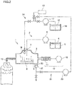
FIG. 2] FIG. 2 is a side view of the gasifier for a sterilizer of the first embodiment including a cleaning liquid circulating device according to the present invention. - [
FIG. 3] FIG. 3 is a side view illustrating a second embodiment of the gasifier for a sterilizer according to the present invention. - [
FIG. 4] FIG. 4 is a side view illustrating the gasifier for a sterilizer of the second embodiment including a cleaning liquid circulating device, according to the present invention. - [
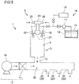
FIG. 5] FIG. 5 is a side view illustrating a third embodiment of the gasifier for a sterilizer according to the present invention. - [
FIG. 6] FIG. 6 is a side view illustrating the gasifier for a sterilizer of the third embodiment including a cleaning liquid circulating device according to the present invention. - Hereinafter, embodiments of the present invention will be described with reference to the drawings.
-
FIG. 1 illustrates a first embodiment of agasifier 1 for a sterilizer according to the present invention. Thegasifier 1 for a sterilizer includes asterilizer supplying portion 2, asterilizer evaporating portion 3, and a heatedair supplying device 12. Thesterilizer supplying portion 2 includes atank 5 that stores asterilizer 4, adropper 7 that drips thesterilizer 4 into thesterilizer evaporating portion 3, and apump 6 that feeds thesterilizer 4 to thedropper 7. Furthermore, thesterilizer evaporating portion 3 includes aheating body 8 that gasifies thesterilizer 4 dripped into thesterilizer evaporating portion 3. The heatedair supplying device 12 includes ablower 10 that feeds air, and aheating device 11 that heats the air fed by theblower 10. - As illustrated in
FIG. 1 , thesterilizer 4 is dripped onto aheating surface 9 of theheating body 8, and thesterilizer 4 is gasified. The produced gas of thesterilizer 4 is blown from a blowingport 13 by heated air. Packaging is sterilized by the gas of thesterilizer 4 which is blown. A stabilizer contained in thesterilizer 4 is deposited when thesterilizer 4 is gasified on theheating surface 9, and the stabilizer adheres to theheating surface 9. - In order to remove the stabilizer adhering to the
heating surface 9, acleaning device 14 that cleans theheating surface 9 is provided at thegasifier 1 for a sterilizer. Thecleaning device 14 includes a cleaningliquid blasting device 18 that blasts a cleaningliquid 15 to theheating surface 9. Further, thecleaning device 14 includes a cleaningliquid tank 16 that stores the cleaningliquid 15, apump 17 that supplies the cleaningliquid 15 to the cleaningliquid blasting device 18, and anair supplying device 19 that supplies air that is blasted to thesterilizer evaporating portion 3 to remove the cleaningliquid 15 from an inside of thesterilizer evaporating portion 3. - The
sterilizer 4 contains at least hydrogen peroxide. The content of the hydrogen peroxide is appropriately in a range of 0.5% by mass to 65% by mass. If the content is lower than 0.5% by mass, the sterilizing power can be insufficient, whereas if the content is higher than 65% by mass, it is difficult to safely handle thesterilizer 4. A more preferable range is 0.5% by mass to 40% by mass. If the content is equal to or lower than 40% by mass, thesterilizer 4 can be more easily handled, and the amount of the hydrogen peroxide remaining on the packaging after sterilization can be reduced because of the low concentration. - Further, the
sterilizer 4 also contains a stabilizer to prevent decomposition of hydrogen peroxide. It is preferable that the stabilizer contained in thesterilizer 4 is sodium pyrophosphate or orthophosphoric acid which is used as a food additive for food products specified by the Minister of Health, Labor and Welfare to sterilize packaging for food. However, an inorganic compound containing phosphorous such as sodium hydrogen pyrophosphate, a phosphonate chelating agent such as aminotrimethylphosphonic acid alkylidenediphosphonate, or the like may also be used. The content of the stabilizer is typically equal to or lower than 40 ppm. - Although the
sterilizer 4 contains water, thesterilizer 4 may contain one or more of alcohols such as methyl alcohol, ethyl alcohol, isopropyl alcohol, normal propyl alcohol and butyl alcohol, ketones such as acetone, methyl ethyl ketone and acetylacetone, and glycol ethers, for example. - Further, the
sterilizer 4 may further contain an additive agent such as a compound having a sterilizing effect such as peracetic acid, acetic acid, a chlorine compound or ozone, a cationic surface active agent and a non-ionic surface active agent. - The
sterilizer 4 stored in thetank 5 is supplied to thedropper 7 by thepump 6, the supply amount is arbitrary, and thesterilizer 4 is supplied based on the required amount of the gas of thesterilizer 4. When the gas of thesterilizer 4 to be supplied is insufficient with the onedropper 7, a plurality ofdroppers 7 is used. The amount of the sterilizer dripped by thedropper 7 is also determined based on the required amount of the gas of the sterilizer, and the amount of the gas produced on theheating surface 9 is determined by the temperature and heat capacity of theheating body 8. - The temperature of the
heating surface 9 of theheating body 8 that gasifies thesterilizer 4 is set at 130°C to 450°C. If the temperature is lower than 130°C, gasification is difficult, whereas if the temperature is higher than 450°C, hydrogen peroxide is decomposed. Further, theheating surface 9 of theheating body 8 may be a planar surface, and horizontal or provided with an inclination, or may be a curved surface such as a concave or convex surface. Theheating surface 9 of theheating body 8 can have any shape as far as thesterilizer 4 can come into contact with theheating surface 9 of theheating body 8 and be gasified. Theheating body 8 can have any size and thickness. When the volume of theheating body 8 is large, the heat capacity is large, which is advantageous for gasification of thesterilizer 4, but thegasifier 1 for a sterilizer becomes excessively large. - For the
heating body 8, a metal such as iron, stainless steel, a copper alloy, aluminum, an aluminum alloy, zinc or tungsten is used. In general, stainless steel having resistance to hydrogen peroxide, such as SUS304, SUS316 or SUS316L is used. - The
heating surface 9 of theheating body 8 may be made of chrome. The material of theheating body 8 itself may be chromium and theheating body 8 may be made of iron, stainless steel, a copper alloy, aluminum, an aluminum alloy, zinc, or tungsten, and the surface of theheating body 8 may be plated with chromium. An outermost surface of the chromium reacts with oxygen to form chromium oxide, which is passive, the outermost surface is extremely stable and does not corrode for a long time even though the hydrogen peroxide contained in thesterilizer 4 at a high temperature comes into contact with the surface. - When the surface of the
heating body 8 is plated with chromium, the thickness of the plating is appropriately 0.1 µm to 100 µm. Before the plating, the material to be plated may be plated with copper or nickel. The surface of the chromium which is plated may be polished to improve the smoothness. - It is estimated that the
heating surface 9 which is the surface of theheating body 8 is made of chromium, whereby decomposition of hydrogen peroxide is reduced when the hydrogen peroxide contained in thesterilizer 4 is gasified, and therefore, the amount of hydrogen peroxide contained in the gas of thesterilizer 4 produced by thegasifier 1 for a sterilizer becomes larger as compared with theheating surface 9 made of stainless steel or the like as in the prior art. - The surface of the
heating surface 9 preferably has an arithmetic mean roughness (Ra) of 1.0 µm or less and a ten-point mean roughness (Rz) of 2.0 µm or less. If Ra is greater than 1.0 µm, or Rz is greater than 2.0 µm, the concentration of hydrogen peroxide in the gas of the sterilizer decreases. It is presumed that this is because if the surface area is large, the sterilizer is excessively heated when the sterilizer comes into contact with theheating surface 9 and is gasified, and thereby hydrogen peroxide is easily decomposed. - The
heating surface 9 of theheating body 8 may be made of polytetrafluoroethylene or perfluoroalkoxy fluorocarbon resin, or chromium plating impregnated with polytetrafluoroethylene or perfluoroalkoxy fluorocarbon resin. Theheating surface 9 is made of polytetrafluoroethylene or perfluoroalkoxy fluorocarbon resin, or a chromium plating impregnated with polytetrafluoroethylene or perfluoroalkoxy fluorocarbon resin, whereby the anti-stick quality of theheating surface 9 can reduce adherence of the stabilizer to theheating surface 9, which is deposited when thesterilizer 4 comes into contact with theheating surface 9 and is gasified. As a result, the number of cleaning times of theheating surface 9 can be reduced. - Polytetrafluoroethylene is a polymer of the monomer tetrafluoroethylene, and has a melting point of about 325°C. The perfluoroalkoxy fluorocarbon resin is a copolymer of tetrafluoroethylene and perfluoroether, and has a melting point of about 310°C. The surface of the
heating body 8 is subjected to a surface treatment such as degreasing, blasting or high-pressure blasting with ceramic particles in order to enhance adhesion, and thereafter the surface of theheating body 8 is coated by a method such as electrostatic powder coating. Further, theheating body 8 coated with polytetrafluoroethylene or perfluoroalkoxy fluorocarbon resin is baked at about 400°C, and thereby theheating surface 9 is formed. The coating and baking may be conducted twice or more times. The thickness of the polytetrafluoroethylene or perfluoroalkoxy fluorocarbon resin is desirably 100 µm to 1000 µm. If the thickness is less than 100 µm, pin holes can occur, whereas if the thickness is greater than 1000 µm, heat conduction from theheating body 8 is compromised. - When the chromium plating impregnated with polytetrafluoroethylene or perfluoroalkoxy fluorocarbon resin is formed on the surface of the
heating body 8, the thickness of the plating is appropriately 1 µm to 100 µm. Before the plating, the material to be plated may be plated with copper or nickel. The surface of the chromium which is plated may be polished to improve the smoothness. - As for a method for heating the
heating body 8, as far as theheating body 8 can be heated to a desired temperature, any method may be adopted, such as passing a current to theheating body 8 to make theheating body 8 itself generate heat, embedding a heater in theheating body 8, placing theheating body 8 in contact with a heater, or heating theheating body 8 with an induction heating device. Further, warm water or steam may be supplied to inside of theheating body 8. - The gas of the
sterilizer 4 produced in thesterilizer evaporating portion 3 is discharged through the blowingport 13 by the heated air fed from the heatedair supplying device 12 and is used to sterilize a packaging such as a bottle. Any amount of heated air can be supplied, but as the amount of the supplied heated air increases, the concentration of hydrogen peroxide contained in the gas of thesterilizer 4 decreases, and the sterilizing power can be poor. Further, as the amount of the supplied heated air is small, the blowing pressure of the gas of thesterilizer 4 to the packaging can be low. The temperature of the heated air is set at 90°C to 350°C. If the temperature is lower than 90°C, there is a risk that thegasified sterilizer 4 may be liquefied before being used for sterilization, so that the covered surface area of the object to be sterilized decreases, and the sterilization effect deteriorates. It is desirable that the gas of thesterilizer 4 comes into contact with the object to be sterilized, the gas of thesterilizer 4 condenses to form fine mist on the object, and the temperature of the heated air is set at an appropriate temperature for achieving this. As the temperature of the heated air is higher than 350°C, some objects to be sterilized can be deformed. Some objects to be sterilized can be deformed at a temperature lower than 350°C, and therefore this should be kept in mind. - The diameter of the blowing
port 13 for the gas of thesterilizer 4 can be arbitrarily set and can be set at 2 mmφ to 200 mmφ, for example. By making the diameter small, the blowing pressure of the produced gas of thesterilizer 4 can be increased. By adjusting the blowing pressure, the intensity of blowing of the gas of thesterilizer 4, the mist generated by condensation of the sterilizer gas, or a mixture thereof onto the surface of the object to be sterilized can be adjusted. For example, if the object to be sterilized is a deep cup, the sterilizer gas and the like can be blown with high intensity, whereas if the object to be sterilized is a shallow container, the sterilizer and the like can be blown with low intensity. If the blowingport 13 is long, the gas of thesterilizer 4 may be cooled and condense, and therefore, the periphery of the blowingport 13 may be heated. - When the
gasifier 1 for a sterilizer is operated for a fixed time period, the stabilizer is deposited on theheating surface 9. In order to remove the deposited stabilizer, the cleaningliquid 15 is blasted to theheating surface 9 from the cleaningliquid blasting device 18. The cleaningliquid 15 is supplied to the cleaningliquid blasting device 18 by thepump 17 from the cleaningliquid tank 16. - The cleaning
liquid 15 is water, or water containing an acidic compound or a basic compound. Water is water sterilized by heating or filtration, pure water, ion exchanged water, distilled water, tap water or the like. The acidic compound is an inorganic acid such as hydrochloric acid, nitric acid, or phosphoric acid, or an organic acid such as acetic acid, formic acid, oxalic acid, citric acid, succinic acid, or gluconic acid. Further, the basic compound is an inorganic basic compound such as sodium hydroxide, or potassium hydroxide, or an organic basic compound such as ethanolamine or diethylamine. In addition to the above, the cleaningliquid 15 may contain alkali metal salt of an organic acid, alkaline earth metal salt, ammonium salt, hydroxycarboxylic acid compound such as alkanolamine salt of ethylenediaminetetraacetic acid or the like, a sequestering agent, an anionic surfactant, a cationic surfactant, a nonionic surfactant such as polyoxyethylene alkyl phenyl ethers, a solubilizer such as sodium cumene sulfonate, an acid based polymer such as polyacrylic acid or metal salt of acid based polymers, a corrosion inhibiter, a preservative, an antioxidant, a dispersant, a defoamer or the like. - The cleaning liquid is prepared by dissolving 0.001% by mass to 30% by mass of an acidic compound or a basic compound into water. When water or aseptic water containing an acidic compound, basic compound or the other additive is used as the cleaning
liquid 15, it is necessary to blast water or aseptic water to theheating surface 9 as the cleaningliquid 15 to remove the acidic compound, the basic compound or the other additive after the water or the aseptic water containing the acidic compound, the basic compound or the other additive is blasted to theheating surface 9. - The cleaning
liquid blasting device 18 is, for example, a one-fluid sprayer, pressure of 0.05 to 0.6 MPa is added to the cleaningliquid 15 by thepump 17, and the cleaningliquid 15 is blasted to theheating surface 9 by the cleaningliquid blasting device 18 which is the one-fluid sprayer. By the pressure of the cleaningliquid 15 which is blasted, the deposited stabilizer is removed from theheating surface 9. Further, the deposited stabilizer is removed by being dissolved in or reacting with the cleaningliquid 15. - The deposited stabilizer is sodium pyrophosphate or orthophosphoric acid contained in hydrogen peroxide. Further, the deposited stabilizer is an inorganic compound containing phosphorous such as sodium hydrogen pyrophosphate or a phosphonate chelating agent such as aminotrimethylphosphonic acid alkylidenediphosphonate, and iron pyrophosphate in which the stabilizer is bound to a metal ion such as iron, or the like is also included.
- When the cleaning
liquid 15 is blasted to theheating surface 9, the temperature of theheating body 8 is preferably 50°C to 250°C. The temperature is more preferably 60°C to 200°C. This is because the higher the temperature of theheating body 8, the higher the cleanability. The cleaningliquid 15 may be blasted to theheating surface 9 when the aseptic filling and packaging machine loaded with thegasifier 1 for a sterilizer is not operating. The cleaningliquid 15 may be blasted to theheating surface 9 periodically, such as once a year, once a month or once a week. However, it is more preferable to carry out the blasting directly after the product is produced by using the aseptic filling and packaging machine, because the stabilizer is efficiently removed. - The cleaning
liquid 15 which is blasted to theheating surface 9 is discharged from the cleaningliquid discharge port 20 provided in a lower part of thesterilizer evaporating portion 3 of thegasifier 1 for a sterilizer. Further, in order to discharge the cleaningliquid 15 remaining inside thesterilizer evaporating portion 3 completely after the cleaningliquid 15 is blasted to theheating surface 9, air is supplied to the cleaningliquid blasting device 18 from theair supplying device 19, and air is blasted to theheating surface 9. Air is pressurized air having a pressure of 0.01 MPa to 1.0 MPa, for example. A device that pressurizes air in theair supplying device 19 may be a blower, or a compressor. A blower and a compressor may be used in combination. Further, the pressurized air may be sterilized air. It is effective to repeat blasting of the cleaningliquid 15 and blasting the pressurized air to theheating surface 9 alternately a plurality of times. - The cleaning
liquid 15 which is discharged from the cleaningliquid discharge port 20 may be directly discarded. However, as illustrated inFIG. 2 , a cleaning liquid circulatingdevice 21 is provided so that the cleaningliquid 15 which is blasted to theheating surface 9 can be recovered and the recovered cleaningliquid 15 can also be blasted to theheating surface 9. The cleaning liquid circulatingdevice 21 includes a dischargeport closing cup 22 for closing the cleaningliquid discharge port 20, and recovering the cleaningliquid 15, and acirculation pump 23 that circulates the recovered cleaningliquid 15 to thecleaning device 14. A balance tank may be provided between the cleaningliquid discharge port 20 and thecirculation pump 23. - The cleaning
liquid discharge port 20 is closed with the dischargeport closing cup 22, all of the cleaningliquid 15 which is discharged is recovered and pressurized by thecirculation pump 23, and the recovered cleaningliquid 15 is circulated into the flow path for the cleaningliquid 15. The recovered cleaningliquid 15 which is circulated is blasted to theheating surface 9 again by the cleaningliquid blasting device 18. In this case, the recovered cleaningliquid 15 may be introduced into the cleaningliquid tank 16, and after the recovered cleaningliquid 15 is stored in the cleaningliquid tank 16, the recovered cleaningliquid 15 may be supplied to the cleaningliquid blasting device 18. - After the cleaning
liquid 15 which is recovered by the cleaning liquid circulatingdevice 21 is blasted to theheating surface 9, it is necessary to blast water or aseptic water to theheating surface 9 as the cleaningliquid 15, detach the dischargeport closing cup 22 from the cleaningliquid discharge port 20, and discard the cleaningliquid 15. This is for removing the stabilizer, the acidic compound or the basic compound, and the other additives from the inside of thesterilizer evaporating portion 3. -
FIG. 3 illustrates a second embodiment of thegasifier 1 for a sterilizer according to the present invention. Thegasifier 1 for a sterilizer includes thesterilizer supplying portion 2 and thesterilizer evaporating portion 3. Thesterilizer supplying portion 2 includes aspraying device 24, and thespraying device 24 supplies thesterilizer 4 to thesterilizer evaporating portion 3. An inner surface of thesterilizer evaporating portion 3 is formed as theheating body 8. Thesterilizer 4 is supplied to thesterilizer supplying portion 2 from a tank not illustrated. - The
sterilizer 4 from thesterilizer supplying portion 2 is supplied to asterilizer supply port 25 of thespraying device 24, and compressed air is supplied to a compressedair supply port 26. The sprayingdevice 24 is a twin-fluid sprayer, and sprays thesterilizer 4 in the form of a mist to the inner surface of thesterilizer evaporating portion 3 from aspray nozzle 27 through anextension pipe 31. The sprayedsterilizer 4 comes into contact with theheating surface 9 of theheating body 8 and is gasified. Theextension pipe 31 is provided to prevent the heat of thesterilizer evaporating portion 3 from being conducted to thespraying device 24 through aplug 30 that closes an upper portion of thesterilizer evaporating portion 3 and increasing the temperature of thespraying device 24. Thegasified sterilizer 4 is discharged from thegas blowing port 13, and is blown to a packaging to sterilize the packaging. The diameter of the blowingport 13 for the gas of thesterilizer 4 can be set arbitrarily as in the first embodiment. - The
sterilizer 4, the materials of theheating body 8 and theheating surface 9 and the like used in the second embodiment are the same as those in the first embodiment. The second embodiment differs from the first embodiment in that the sterilizer is supplied to thesterilizer evaporating portion 3 by spraying a mist of the sterilizer, theheating body 8 forms the inner surface of thesterilizer evaporating portion 3 and has a cylindrical shape, and the heatedair supplying device 12 is not included. - The inner surface of the
sterilizer evaporating portion 3 forms theheating body 8 in the cylindrical shape, aheater 28 for heating theheating body 8 is provided on an outer surface of thesterilizer evaporating portion 3, andouter covering 29 is further provided on an outer surface of theheater 28 to provide heat insulating properties and protect theheater 28. WhileFIG. 3 shows that theheater 28 heats theheating body 8, a heating method of theheating body 8 may be any heating method as in the first embodiment. - With regard to operating conditions of the
spraying device 24, the pressure of the compressed air is adjusted within a range of 0.05 MPa to 0.6 MPa, for example. Further, thesterilizer 4 may be supplied by gravity or under pressure using thepump 6, the supply amount of thesterilizer 4 can be arbitrarily set, and the sterilizer is supplied at a rate within a range of 1 g/min to 100 g/min, for example. - The
sterilizer 4 is sprayed in a circular pattern through thespray nozzle 27, and therefore theheating body 8 preferably has a circular cylindrical shape. However, theheating body 8 may have a polygonal cylindrical shape. A diameter of the cylinder needs to be sufficiently large to prevent the internal pressure of thesterilizer evaporating portion 3 from being increased by the compressed air used to spray thesterilizer 4. For example, the diameter of the cylinder can be set to be 1 mmφ to 1000 mmφ. On the other hand, the diameter has to be such a diameter that the sprayed mist of thesterilizer 4 comes into contact with theheating surface 9. Further, the length of the cylinder is also designed so as to meet the conditions. - When the
gasifier 1 for a sterilizer is operated for a fixed time period, the stabilizer contained in thesterilizer 4 is deposited and accumulated on theheating surface 9 of theheating body 8. In order to clean theheating surface 9 to remove the deposited stabilizer, thecleaning device 14 for cleaning theheating surface 9 is provided in thegasifier 1 for a sterilizer of the second embodiment as in the first embodiment, as illustrated inFIG. 3 . - The
cleaning device 14 includes the cleaningliquid blasting device 18. Further, thecleaning device 14 includes the cleaningliquid tank 16 that stores the cleaningliquid 15 to be blasted to theheating surface 9, thepump 17 that supplies the cleaningliquid 15 to the cleaningliquid blasting device 18, and theair supplying device 19 that supplies air to the cleaningliquid blasting device 18 to remove the cleaningliquid 15 from the inside of thesterilizer evaporating portion 3. - The cleaning
liquid 15 is blasted to theheating surface 9 that forms the inner surface of thesterilizer evaporating portion 3 from the cleaningliquid blasting device 18. The blasted cleaningliquid 15 is discharged from the blowingport 13. In the second embodiment, the blowingport 13 also functions as the cleaningliquid discharge port 20. Although the two cleaningliquid blasting devices 18 are shown inFIG. 3 , only the one cleaningliquid blasting device 18 may be used, if the one cleaningliquid blasting device 18 can clean theheating surface 9. Further, three or more cleaningliquid blasting devices 18 may be used if necessary. - The cleaning
liquid 15 similar to that in the first embodiment is used. Further, when water or aseptic water containing an acidic compound, basic compound or other additives is used as the cleaningliquid 15, it is also necessary to blast the water or aseptic water to theheating surface 9 as the cleaningliquid 15 to remove the acidic compound or the basic compound from the inside of thesterilizer evaporating portion 3 after the cleaning liquid is blasted to theheating surface 9 as in the first embodiment. - The cleaning
liquid blasting device 18 is a one-fluid sprayer, for example, thepump 17 adds a pressure of 0.05 MPa to 0.6 MPa to the cleaningliquid 15, and the cleaningliquid blasting device 18 which is the one-fluid sprayer blasts the cleaningliquid 15 to theheating surface 9. The pressure of the blasted cleaningliquid 15 removes the deposited stabilizer from theheating surface 9. Further, the stabilizer is dissolved into the cleaningliquid 15, or the stabilizer reacts with the acidic compound or the basic compound contained in the cleaningliquid 15, and thereby the stabilizer adhering to theheating surface 9 is removed. - The cleaning
liquid 15 which is blasted to theheating surface 9 is discharged from the blowingport 13 provided in the lower part of thesterilizer evaporating portion 3 of thegasifier 1 for a sterilizer, which also functions as the cleaningliquid discharge port 20. In order to completely discharge the cleaningliquid 15 remaining inside thesterilizer evaporating portion 3 after the cleaningliquid 15 is blasted to theheating surface 9, air is supplied to the cleaningliquid blasting device 18 from theair supplying device 19 included in thecleaning device 14, and is blasted to theheating surface 9. As the air, pressurized air having a pressure of 0.1 MPa to 1.0 MPa is used. - A cleaning step is as follows. After the operation of the
gasifier 1 for a sterilizer is stopped, and the temperature of theheating body 8 decreases, the cleaningliquid 15 is blasted to theheating surface 9 for a fixed time period by the cleaningliquid blasting device 18, and thereafter, the blasting is stopped. After the temperature of theheating body 8 decreases to a room temperature, blasting of the cleaningliquid 15 to theheating surface 9 may be started, and the temperature of theheating body 8 is preferably 50°C to 250°C. The temperature of theheating body 8 is more preferably 60°C to 150°C. The higher the temperature of theheating body 8, the higher the cleanability, which is preferable. However, when the temperature of theheating body 8 becomes higher than 250°C, the cleaningliquid 15 is gasified, and the internal pressure of thesterilizer evaporating portion 3 increases. - After a fixed time period elapses after stopping blasting of the cleaning
liquid 15, the cleaningliquid 15 is blasted for a fixed time period again, and the blasting is stopped. This is repeated several times, and further, air is blasted into thesterilizer evaporating portion 3 for a fixed time period by the cleaningliquid blasting device 18, and the cleaningliquid 15 is removed from the inside of thesterilizer evaporating portions 3. If the diameter of the blowingport 13 which also functions as the cleaningliquid discharge port 20 is taken into consideration, and the cleaningliquid 15 is blasted in a flow amount that fills the inside of thesterilizer evaporating portion 3 with the cleaningliquid 15, it becomes possible to clean thesterilizer evaporating portion 3 up to a top surface of an upper portion of thesterilizer evaporating portion 3. Thereafter, the temperature of theheating body 8 is increased, and when the temperature of theheating body 8 reaches a set temperature, thesterilizer 4 is sprayed into thesterilizer evaporating portion 3 by the sprayingdevice 24 for a fixed time period. Thereafter, an operation of thegasifier 1 for a sterilizer is started. - The cleaning
liquid 15 which is discharged from the cleaningliquid discharge port 20 may be directly discarded. However, as illustrated inFIG. 4 , the cleaning liquid circulatingdevice 21 is provided so that the cleaningliquid 15 which is blasted to theheating surface 9 can be recovered and the recovered cleaningliquid 15 can also be blasted to theheating surface 9, as in the first embodiment. The cleaning liquid circulatingdevice 21 includes the dischargeport closing cup 22 for closing the blowingport 13 which is the cleaningliquid discharge port 20, and recovering the cleaningliquid 15, and thecirculation pump 23 that circulates the recovered cleaningliquid 15. A balance tank may be provided between the blowingport 13 which also functions as the cleaningliquid discharge port 20 and thecirculation pump 23. - The cleaning
liquid discharge port 20 may be closed with the dischargeport closing cup 22, all of the cleaningliquid 15 which is discharged may be recovered, and pressurized by thecirculation pump 23, and the recovered cleaningliquid 15 may be introduced into the flow path for the cleaningliquid 15. The recovered cleaningliquid 15 which is introduced is blasted to theheating surface 9 again by the cleaningliquid blasting device 18. In this case, the recovered cleaningliquid 15 may be introduced into the cleaningliquid tank 16, and after the recovered cleaningliquid 15 is stored in the cleaningliquid tank 16, the recovered cleaningliquid 15 may be supplied to the cleaningliquid blasting device 18. - After the cleaning
liquid 15 which is recovered by the cleaning liquid circulatingdevice 21 is blasted to theheating surface 9, water or aseptic water is blasted to theheating surface 9 as the cleaningliquid 15. At this time, the dischargeport closing cup 22 has to be detached from the blowingport 13, and the cleaningliquid 15 has to be discarded. This is for removing the stabilizer, the acidic compound, the basic compound, and the other additives from the inside of thesterilizer evaporating portion 3. Further, while thegasifier 1 for a sterilizer is operating, the gas of thesterilizer 4 is blown to packaging from the blowingport 13, and therefore the dischargeport closing cup 22 is detached and is held so as not to interfere with the operation. - Although in the second embodiment, the cleaning
liquid 15 is blasted to theheating surface 9 from the cleaningliquid blasting device 18, the cleaningliquid 15 may be supplied to thespraying device 24 from thesterilizer supply port 25, and the cleaningliquid 15 may be blasted into thesterilizer evaporating portion 3 from thespray nozzle 27. In this case, the cleaningliquid 15 is stored in the cleaningliquid tank 16, and is supplied to thesterilizer supply port 25 by thepump 17. The sprayingdevice 24 is equipped with the compressedair supply port 26, and does not need theair supplying device 19. In other words, after the cleaningliquid 15 is blasted to theheating surface 9 from thespray nozzle 27, the compressed air which is supplied to thespraying device 24 from the compressedair supply port 26 is blasted to theheating surface 9 from thespray nozzle 27, and the cleaningliquid 15 which remains in thesterilizer evaporating portion 3 is removed. - An inside of the
extension pipe 31 is not cleaned by the cleaningliquid blasting device 18. The heat of theheating body 8 is conducted to theextension pipe 31, a temperature in a vicinity of theheating body 8 increases, and the stabilizer contained in the sterilizer is likely to be deposited. The inside of theextension pipe 31 may be cleaned by being supplied with the cleaningliquid 15 from thesterilizer supply port 25. In order to increase cleanability, an inside diameter of theextension pipe 31 is preferably 3 mmφ or more. -
FIG. 5 illustrates a third embodiment of thegasifier 1 for a sterilizer according to the present invention. Thesterilizer 4 and the cleaningliquid 15 which are similar to those in the first embodiment are used. Further, for gasification of thesterilizer 4, thegasifier 1 for a sterilizer similar to that of the second embodiment is used, and is operated as in the second embodiment. - The
sterilizer 4 which is gasified by thesterilizer evaporating portion 3 is discharged from the blowingport 13 by pressure of the compressed air. The blowingport 13 is caused to face an object to be sterilized, and the gas of thesterilizer 4 to be discharged can be directly blown to a packaging which is the object to be sterilized. However, as illustrated inFIG. 5 , the heatedair supplying device 12 that introduces heated air is included in an end portion of thesterilizer evaporating portion 3, the gas of thesterilizer 4 which is discharged from the blowingport 13 and the heated air may be mixed in aconduit pipe 32, and the mixed gas may be blown to the packaging from a sterilizergas blowing port 33. The heatedair supplying device 12 includes ablower 10 and aheating device 11, and heats the air by theblower 10 by theheating device 11. - A plurality of
sterilizer evaporating portions 3 of thegasifier 1 for a sterilizer may be connected to theconduit pipe 32 instead of the onesterilizer evaporating portion 3. Further, the number of sterilizergas blowing ports 33 may be one or more. The air is heated to 130°C to 300°C by theheating device 11. The temperature of the heated air is set similarly to the first embodiment. A sanitary valve is preferably provided downstream of theheating device 11 so that the cleaningliquid 15 does not flow backward. - After the
gasifier 1 for a sterilizer is operated for a fixed time period, the cleaningliquid 15 is blasted to the inner surface of thesterilizer evaporating portion 3 by the cleaningliquid blasting device 18 to clean theheating surface 9, and the cleaningliquid 15 is discharged from the sterilizergas blowing port 33 which also functions as the cleaningliquid discharge port 20. After the cleaningliquid 15 is blasted to theheating surface 9, the pressurized air which is supplied from theair supplying device 19 is blasted to theheating surface 9 to completely discharge the cleaningliquid 15 which remains inside thesterilizer evaporating portion 3. As for the air pressure, the pressurized air of 0.1 MPa to 1.0 MPa is used. - The cleaning
liquid 15 which is discharged from the sterilizergas blowing port 33 which also functions as the cleaningliquid discharge port 20 may be directly discarded. However, as illustrated inFIG. 6 , the cleaning liquid circulatingdevice 21 can be provided as in the first embodiment, so that the cleaningliquid 15 which is blasted to theheating surface 9 can be recovered and the recovered cleaningliquid 15 can also be blasted to theheating surface 9. The cleaning liquid circulatingdevice 21 includes the dischargeport closing cup 22 for closing the sterilizergas blowing port 33 which is the cleaningliquid discharge port 20, and recovering the cleaningliquid 15, and thecirculation pump 23 that circulates the recovered cleaningliquid 15. - The sterilizer
gas blowing port 33 which is the cleaningliquid discharge port 20 is closed with the dischargeport closing cup 22, all of the cleaningliquid 15 which is discharged is recovered and is pressurized by thecirculation pump 23, and the recovered cleaningliquid 15 is introduced into the flow path for the cleaningliquid 15. The introducedcleaning liquid 15 is blasted to theheating surface 9 again by the cleaningliquid blasting device 18. In this case, the recovered cleaningliquid 15 may be introduced into the cleaningliquid tank 16, and after the recovered cleaningliquid 15 is stored in the cleaningliquid tank 16, the recovered cleaningliquid 15 may be supplied to the cleaningliquid blasting device 18. - After the cleaning
liquid 15 which is recovered by the cleaning liquid circulatingdevice 21 is blasted to theheating surface 9, it is necessary to blast water or aseptic water to theheating surface 9 as the cleaningliquid 15, detach the dischargeport closing cup 22 from the sterilizergas blowing port 33, and discard the cleaningliquid 15. This is for removing the stabilizer, the acidic compound or the basic compound, and the other additives from the inside of thesterilizer evaporating portion 3. Further, during an operation, the gas of thesterilizer 4 is blown to packaging from the sterilizergas blowing port 33, and therefore the dischargeport closing cup 22 is detached, and is held so as not to interfere with the operation. - Although in the third embodiment, the cleaning
liquid 15 is blasted to theheating surface 9 from the cleaningliquid blasting device 18 as in the second embodiment, the cleaningliquid 15 may be supplied to thespraying device 24 from thesterilizer supply port 25, and the cleaningliquid 15 may be blasted into thesterilizer evaporating portion 3 from thespray nozzle 27. - Hereinafter, the present invention will be described based on examples.
- The
gasifier 1 for a sterilizer illustrated in the second embodiment was used. Here, SUS316L was adopted as the material of theheating body 8 on the inner surface of thesterilizer evaporating portion 3, and theheating surface 9 is made of the same material as theheating body 8. As thesterilizer 4, a hydrogen peroxide solution containing 35% by mass of hydrogen peroxide and a stabilizer was supplied at 65 g/min to thesterilizer supply port 25 of thespraying device 24 which is a twin-fluid sprayer. Further, compressed air of 0.5 MPa was supplied to the compressedair supply port 26. The temperature of theheating body 8 was set at 300°C. Thegasifier 1 for a sterilizer was operated for 24 hours under the above described conditions, and thereafter, cleaning as follows was conducted. - After the operation of the
gasifier 1 for a sterilizer was stopped, and the temperature of theheating body 8 decreases to 150°C or less, pressure of 0.2 MPa was added by thepump 17, and aseptic water was blasted to theheating surface 9 in thesterilizer evaporating portion 3 from the two cleaningliquid blasting devices 18 for 60 seconds. The blasting was stopped for 60 seconds, and blasting was further conducted for 60 seconds. This was repeated five times. Thereafter, air under pressure of 0.5 MPa was blasted into thesterilizer evaporating portion 3 from the two cleaningliquid blasting devices 18 for three minutes. Then, theheating body 8 was increased in temperature, and after the temperature of theheating body 8 reaches 300°C, thesterilizer 4 was sprayed from the sprayingdevice 24 for 10 minutes. Thereafter, the operation of thegasifier 1 for a sterilizer was restarted. The operation was conducted for 300 days, and then the inner surface of thesterilizer evaporating portion 3 was observed. The example shows the case where cleaning was repeatedly conducted, whereas a comparative example shows a case where thegasifier 1 for a sterilizer was operated continuously without conducting cleaning even once. - According to the above described example, by cleaning the
heating surface 9 of thegasifier 1 for a sterilizer, the stabilizer did not adhere to theheating surface 9 after the operation for a long time period, and accumulation of the stabilizer was able to be prevented. On the other hand, in the comparative example where cleaning was not conducted, accumulation of the stabilizer was confirmed. - According to the present invention, the
gasifier 1 for a sterilizer was able to exhibit stable gasifying performance of thesterilizer 4 for a long time period without having accumulation of the stabilizer on theheating surface 9, and without losing heat conductivity from theheating body 8 to theheating surface 9. Further, the stabilizer no longer condenses to be a solid to enter packaging. - Although the present invention is configured as described above, the present invention is not limited to the above described embodiments, but can be variously changed within the gist of the present invention.
- For example, when the
heating body 8 of thegasifier 1 for a sterilizer is heated by an electric heating device, accumulation of the stabilizer onto theheating surface 9 is assumed to occur as a heating current value decreases. Therefore, the current output value may be monitored, and the value may be automatically reflected in cleaning parameters such as the blasting time period of the cleaningliquid 15 and the temperature of theheating body 8. Further, a hydrogen peroxide gas concentration measuring instrument may be provided in the blowingport 13 of thegasifier 1 for a sterilizer, the gasifying state of thegasifier 1 for a sterilizer may be monitored, and the gasifying state may be automatically reflected in the cleaning parameters such as the blasting time period of the cleaningliquid 15 and the temperature of theheating body 8. -
- 1
- gasifier for sterilizer
- 2
- sterilizer supplying portion
- 14
- cleaning device
- 15
- cleaning liquid
- 18
- cleaning liquid blasting device
- 19
- air supplying device
- 21
- cleaning liquid circulating device
Claims (10)
- A gasifier for a sterilizer that brings a sterilizer containing at least hydrogen peroxide and a stabilizer into contact with a heating surface to gasify the sterilizer,
wherein a cleaning device that cleans the heating surface is provided, and the cleaning device comprises a cleaning liquid blasting device that blasts a cleaning liquid to the heating surface. - The gasifier for a sterilizer according to claim 1,
wherein the cleaning device comprises a tank that stores the cleaning liquid, a pump that supplies the cleaning liquid to the cleaning liquid blasting device, and an air supplying device that supplies air to the cleaning liquid blasting device. - The gasifier for a sterilizer according to claim 1 or claim 2,
wherein the cleaning liquid blasting device is a one-fluid sprayer. - The gasifier for a sterilizer according to any one of claim 1 to claim 3,
wherein a cleaning liquid circulating device having a discharge port closing cup that closes a cleaning liquid discharge port from which the cleaning liquid is discharged, and recovers the cleaning liquid which is discharged, and a circulation pump that supplies the recovered cleaning liquid to the cleaning device is provided. - The gasifier for a sterilizer according to any one of claim 1 to claim 4,
wherein the heating surface has a cylindrical shape. - A cleaning method of a gasifier for a sterilizer that brings a sterilizer containing at least hydrogen peroxide and a stabilizer into contact with a heating surface to gasify the sterilizer,
wherein the heating surface is cleaned by blasting a cleaning liquid to the heating surface. - The cleaning method of a gasifier for a sterilizer according to claim 6,
wherein the cleaning liquid is water or water containing an acidic compound or a basic compound. - The cleaning method of a gasifier for a sterilizer according to claim 6 or claim 7,
wherein after the cleaning liquid is blasted to the heating surface, air is blasted to the heating surface. - The cleaning method of a gasifier for a sterilizer according to any one of claim 6 to claim 8,
wherein the cleaning liquid discharge port from which the cleaning liquid is discharged is closed, the cleaning liquid which is blasted to the heating surface is recovered, and the recovered cleaning liquid is blasted to the heating surface. - The cleaning method of a gasifier for a sterilizer according to any one of claim 6 to claim 9,
wherein the heating surface has a cylindrical shape.
Priority Applications (1)
| Application Number | Priority Date | Filing Date | Title |
|---|---|---|---|
| EP25208574.1A EP4706693A1 (en) | 2017-02-20 | 2018-02-20 | Gasifying device for sterilization agent and method for cleaning gasifying device for sterilization agent |
Applications Claiming Priority (2)
| Application Number | Priority Date | Filing Date | Title |
|---|---|---|---|
| JP2017029250 | 2017-02-20 | ||
| PCT/JP2018/005854 WO2018151308A1 (en) | 2017-02-20 | 2018-02-20 | Gasifying device for sterilization agent and method for cleaning gasifying device for sterilization agent |
Related Child Applications (2)
| Application Number | Title | Priority Date | Filing Date |
|---|---|---|---|
| EP25208574.1A Division-Into EP4706693A1 (en) | 2017-02-20 | 2018-02-20 | Gasifying device for sterilization agent and method for cleaning gasifying device for sterilization agent |
| EP25208574.1A Division EP4706693A1 (en) | 2017-02-20 | 2018-02-20 | Gasifying device for sterilization agent and method for cleaning gasifying device for sterilization agent |
Publications (3)
| Publication Number | Publication Date |
|---|---|
| EP3583957A1 true EP3583957A1 (en) | 2019-12-25 |
| EP3583957A4 EP3583957A4 (en) | 2020-12-23 |
| EP3583957B1 EP3583957B1 (en) | 2026-01-14 |
Family
ID=63170394
Family Applications (2)
| Application Number | Title | Priority Date | Filing Date |
|---|---|---|---|
| EP25208574.1A Pending EP4706693A1 (en) | 2017-02-20 | 2018-02-20 | Gasifying device for sterilization agent and method for cleaning gasifying device for sterilization agent |
| EP18753557.0A Active EP3583957B1 (en) | 2017-02-20 | 2018-02-20 | Gasifier for sterilizer and cleaning method of gasifier for sterilizer |
Family Applications Before (1)
| Application Number | Title | Priority Date | Filing Date |
|---|---|---|---|
| EP25208574.1A Pending EP4706693A1 (en) | 2017-02-20 | 2018-02-20 | Gasifying device for sterilization agent and method for cleaning gasifying device for sterilization agent |
Country Status (6)
| Country | Link |
|---|---|
| US (3) | US11305029B2 (en) |
| EP (2) | EP4706693A1 (en) |
| JP (5) | JP6888636B2 (en) |
| CN (3) | CN113663966A (en) |
| MY (1) | MY195893A (en) |
| WO (1) | WO2018151308A1 (en) |
Cited By (1)
| Publication number | Priority date | Publication date | Assignee | Title |
|---|---|---|---|---|
| WO2025247900A1 (en) | 2024-05-29 | 2025-12-04 | Khs Gmbh | Sterilizing agent vaporizer, container treatment system and method for operating a sterilizing agent vaporizer |
Families Citing this family (7)
| Publication number | Priority date | Publication date | Assignee | Title |
|---|---|---|---|---|
| EP3730156A1 (en) * | 2019-04-25 | 2020-10-28 | Sidel Participations | Treatment machine for treating receptacles and method of operating such a treatment machine |
| IT202000005338A1 (en) * | 2020-03-12 | 2020-06-12 | Ur Fog S R L | SANITIZER / DISINFECTANT DEVICE AND COMPOSITION OF SANITIZING / DISINFECTANT FLUID |
| FR3116463B1 (en) | 2020-11-26 | 2023-11-03 | Sidel Participations | Forming machine comprising a device for sterilizing a blowing network |
| CN114288450B (en) * | 2021-12-14 | 2024-02-23 | 深圳市永恒丰智能设备有限公司 | Evaporation type atomizer for sterilizing germs |
| DE102023101887A1 (en) * | 2023-01-26 | 2024-08-01 | Khs Gmbh | Device for evaporating a liquid sterilizing agent and method for cleaning the device |
| IT202400000519A1 (en) * | 2024-01-12 | 2025-07-12 | Saccardo Arturo Figli Srl | INTERNAL WASHING SYSTEM FOR EVACUATION STATIONS FOR VACUUM PACKAGING MACHINES |
| CN118716652B (en) * | 2024-09-03 | 2024-11-15 | 福建正味生物科技有限公司 | Processing method for preparing composite flavoring agent by spraying technology |
Family Cites Families (38)
| Publication number | Priority date | Publication date | Assignee | Title |
|---|---|---|---|---|
| JPS60220067A (en) | 1984-04-13 | 1985-11-02 | 雪印乳業株式会社 | Method and apparatus for sterilizing packing material |
| JPS6311163A (en) | 1986-03-24 | 1988-01-18 | 雪印乳業株式会社 | Sterilizing method and apparatus |
| JPH0670922B2 (en) | 1988-08-25 | 1994-09-07 | 日立金属株式会社 | Magnetic parts for high voltage pulse generator |
| JP3071446B2 (en) | 1989-12-29 | 2000-07-31 | 大日本印刷株式会社 | Method and apparatus for sterilizing packaging material |
| JP2918413B2 (en) * | 1993-03-18 | 1999-07-12 | 住友重機械工業株式会社 | Method for removing calcium sulfate scale in evaporator |
| US6808681B2 (en) | 1996-10-14 | 2004-10-26 | Tetra Laval Holdings & Finance Sa | Method of sterilizing a package material |
| SE507994C2 (en) * | 1996-10-14 | 1998-08-10 | Tetra Laval Holdings & Finance | Ways of sterilizing packaging material |
| JPH10218134A (en) | 1997-02-03 | 1998-08-18 | Toppan Printing Co Ltd | Sterilizer vaporizer |
| JP4075093B2 (en) | 1997-03-18 | 2008-04-16 | 凸版印刷株式会社 | Container sterilizer |
| JPH1111913A (en) * | 1997-06-19 | 1999-01-19 | Mitsubishi Gas Chem Co Inc | Hydrogen peroxide composition |
| US6106772A (en) * | 1997-06-23 | 2000-08-22 | Ethicon, Inc. | Injector impinger |
| DE19742822B4 (en) * | 1997-09-27 | 2005-09-29 | Sig Combibloc Gmbh | Device for sterilizing packaging material |
| JP2001224669A (en) * | 2000-02-16 | 2001-08-21 | Shikoku Kakoki Co Ltd | Sterilizing liquid gasifier |
| JP4431807B2 (en) * | 2000-04-04 | 2010-03-17 | 四国化工機株式会社 | Sterilizer gasifier |
| US20020098111A1 (en) * | 2000-12-04 | 2002-07-25 | Nguyen Nick N. | Vaporizer |
| JP4526820B2 (en) * | 2001-09-05 | 2010-08-18 | 大日本印刷株式会社 | PET bottle sterilization method and sterilizer |
| US7803315B2 (en) * | 2001-10-05 | 2010-09-28 | American Sterilizer Company | Decontamination of surfaces contaminated with prion-infected material with gaseous oxidizing agents |
| DE10201089A1 (en) * | 2002-01-14 | 2003-07-31 | P & W Invest Vermoegensverwalt | Process for the disinfection and cleaning of water-bearing systems, in particular in swimming and bathing pool systems, and device for carrying it out |
| JP2006240969A (en) | 2005-03-07 | 2006-09-14 | Mitsubishi Gas Chem Co Inc | Hydrogen peroxide solution for aseptic filling equipment |
| JP2006286665A (en) * | 2005-03-31 | 2006-10-19 | Toshiba Corp | Electronic device cleaning method and electronic device cleaning apparatus |
| TW200703482A (en) * | 2005-03-31 | 2007-01-16 | Toshiba Kk | Method and apparatus for cleaning electronic device |
| JPWO2006123636A1 (en) * | 2005-05-19 | 2008-12-25 | 三菱瓦斯化学株式会社 | Hydrogen peroxide solution for sterilization |
| AU2006275320B2 (en) * | 2005-08-04 | 2012-03-08 | Saban Ventures Pty Limited | Apparatus for concentrating a nebulant |
| EP1762252A1 (en) * | 2005-09-12 | 2007-03-14 | SOLVAY (Société Anonyme) | Aqueous solution suitable for the chemical sterilization of packaging materials, process for its preparation and its use |
| CN201335368Y (en) * | 2008-12-29 | 2009-10-28 | 中铁二院工程集团有限责任公司 | Spraying structure |
| JP5831673B2 (en) * | 2010-01-22 | 2015-12-09 | 東洋製罐株式会社 | Spatial surface sterilization method |
| CN101812387B (en) * | 2010-04-29 | 2013-01-23 | 燕京啤酒(浙江仙都)有限公司 | Method for producing fresh beer |
| WO2012046555A1 (en) * | 2010-10-07 | 2012-04-12 | 東洋製罐株式会社 | Container sterilization method, and three-fluid nozzle used in sterilization method |
| PT2825212T (en) * | 2012-03-13 | 2018-03-14 | Peroxychem Llc | SUMMARY |
| EP3620426B1 (en) * | 2012-11-16 | 2023-03-01 | Dai Nippon Printing Co., Ltd. | Apparatus for filling a drink comprising means for cleaning and sterilizing the apparatus |
| EP3120940B1 (en) * | 2012-12-21 | 2021-11-17 | Dai Nippon Printing Co., Ltd. | Beverage filling method |
| CN203196964U (en) * | 2013-04-23 | 2013-09-18 | 山东新华医疗器械股份有限公司 | Movable pot cleaning machine for pharmaceutical factory |
| TWI642452B (en) * | 2013-07-18 | 2018-12-01 | 日商三菱瓦斯化學股份有限公司 | Aqueous hydrogen peroxide solution for sterilization and manufacturing method thereof |
| JP2015077584A (en) * | 2013-10-15 | 2015-04-23 | 中外鉱業株式会社 | Desalination plant |
| WO2015078830A1 (en) * | 2013-11-26 | 2015-06-04 | Solvay Sa | Aqueous solution suitable for the chemical sterilization of packaging materials, process for its preparation and its use |
| CN203621049U (en) * | 2013-12-13 | 2014-06-04 | 山东新华医疗器械股份有限公司 | Hopper cleaning station |
| WO2016114273A1 (en) * | 2015-01-16 | 2016-07-21 | 三菱瓦斯化学株式会社 | Disinfectant and disinfection method using same |
| JP6473057B2 (en) * | 2015-07-23 | 2019-02-20 | 三菱重工機械システム株式会社 | Bactericidal agent vaporizing method and vaporizing apparatus |
-
2018
- 2018-02-20 EP EP25208574.1A patent/EP4706693A1/en active Pending
- 2018-02-20 US US16/478,601 patent/US11305029B2/en active Active
- 2018-02-20 CN CN202110836124.3A patent/CN113663966A/en active Pending
- 2018-02-20 EP EP18753557.0A patent/EP3583957B1/en active Active
- 2018-02-20 CN CN202110836118.8A patent/CN113648669A/en active Pending
- 2018-02-20 JP JP2018568661A patent/JP6888636B2/en active Active
- 2018-02-20 CN CN201880008762.2A patent/CN110248684B/en active Active
- 2018-02-20 WO PCT/JP2018/005854 patent/WO2018151308A1/en not_active Ceased
- 2018-02-20 MY MYPI2019004266A patent/MY195893A/en unknown
-
2021
- 2021-05-12 JP JP2021081272A patent/JP7074238B2/en active Active
- 2021-05-12 JP JP2021081269A patent/JP7136270B2/en active Active
- 2021-05-12 JP JP2021081271A patent/JP7074237B2/en active Active
- 2021-05-12 JP JP2021081270A patent/JP7074236B2/en active Active
-
2022
- 2022-02-07 US US17/650,110 patent/US11872323B2/en active Active
- 2022-02-07 US US17/650,108 patent/US11806437B2/en active Active
Cited By (1)
| Publication number | Priority date | Publication date | Assignee | Title |
|---|---|---|---|---|
| WO2025247900A1 (en) | 2024-05-29 | 2025-12-04 | Khs Gmbh | Sterilizing agent vaporizer, container treatment system and method for operating a sterilizing agent vaporizer |
Also Published As
| Publication number | Publication date |
|---|---|
| JP2021120007A (en) | 2021-08-19 |
| JP2021112670A (en) | 2021-08-05 |
| US11305029B2 (en) | 2022-04-19 |
| EP3583957B1 (en) | 2026-01-14 |
| JP7074236B2 (en) | 2022-05-24 |
| JP2021112669A (en) | 2021-08-05 |
| JP7074237B2 (en) | 2022-05-24 |
| JP6888636B2 (en) | 2021-06-16 |
| EP3583957A4 (en) | 2020-12-23 |
| US11872323B2 (en) | 2024-01-16 |
| US11806437B2 (en) | 2023-11-07 |
| JP2021112668A (en) | 2021-08-05 |
| US20220152246A1 (en) | 2022-05-19 |
| US20200046867A1 (en) | 2020-02-13 |
| CN110248684B (en) | 2021-07-27 |
| WO2018151308A1 (en) | 2018-08-23 |
| JP7136270B2 (en) | 2022-09-13 |
| CN113648669A (en) | 2021-11-16 |
| CN110248684A (en) | 2019-09-17 |
| JP7074238B2 (en) | 2022-05-24 |
| MY195893A (en) | 2023-02-27 |
| CN113663966A (en) | 2021-11-19 |
| JPWO2018151308A1 (en) | 2019-11-07 |
| EP4706693A1 (en) | 2026-03-11 |
| US20220152247A1 (en) | 2022-05-19 |
Similar Documents
| Publication | Publication Date | Title |
|---|---|---|
| US11872323B2 (en) | Gasifier for sterilizer and cleaning method of gasifier for sterilizer | |
| EP3744182B1 (en) | Gasifier for sterilizer | |
| JP7434749B2 (en) | Sterilization method and sterilization device in sterile water supply piping of aseptic filling machine | |
| US11884529B2 (en) | Aseptic filling apparatus and method for cooling filling valve of aseptic filling apparatus | |
| JP7017065B2 (en) | Disinfectant gasifier | |
| JP6642454B2 (en) | Disinfectant and disinfection method using the same | |
| EP4353273A1 (en) | Disinfectant vaporizing device and disinfectant vaporizing method | |
| JP6365645B2 (en) | Disinfectant gasifier | |
| EP3542643B1 (en) | Sanitizer gasification apparatus | |
| JP7021664B2 (en) | Gasification device for disinfectant and gasification method for disinfectant | |
| JP7585650B2 (en) | Sterilant gasifier | |
| JP2023055367A (en) | Sterilization method and sterilization apparatus for inside of sterile water supply pipeline of aseptic filling machine |
Legal Events
| Date | Code | Title | Description |
|---|---|---|---|
| STAA | Information on the status of an ep patent application or granted ep patent |
Free format text: STATUS: THE INTERNATIONAL PUBLICATION HAS BEEN MADE |
|
| PUAI | Public reference made under article 153(3) epc to a published international application that has entered the european phase |
Free format text: ORIGINAL CODE: 0009012 |
|
| STAA | Information on the status of an ep patent application or granted ep patent |
Free format text: STATUS: REQUEST FOR EXAMINATION WAS MADE |
|
| 17P | Request for examination filed |
Effective date: 20190801 |
|
| AK | Designated contracting states |
Kind code of ref document: A1 Designated state(s): AL AT BE BG CH CY CZ DE DK EE ES FI FR GB GR HR HU IE IS IT LI LT LU LV MC MK MT NL NO PL PT RO RS SE SI SK SM TR |
|
| AX | Request for extension of the european patent |
Extension state: BA ME |
|
| DAV | Request for validation of the european patent (deleted) | ||
| DAX | Request for extension of the european patent (deleted) | ||
| A4 | Supplementary search report drawn up and despatched |
Effective date: 20201125 |
|
| RIC1 | Information provided on ipc code assigned before grant |
Ipc: B08B 3/02 20060101ALI20201119BHEP Ipc: C08K 5/00 20060101ALI20201119BHEP Ipc: B01D 1/00 20060101ALI20201119BHEP Ipc: B01D 1/16 20060101ALI20201119BHEP Ipc: A61L 2/18 20060101ALI20201119BHEP Ipc: B65B 55/10 20060101ALI20201119BHEP Ipc: B01D 1/14 20060101ALI20201119BHEP Ipc: A61L 2/20 20060101AFI20201119BHEP Ipc: B01D 1/22 20060101ALI20201119BHEP Ipc: B08B 5/02 20060101ALI20201119BHEP |
|
| STAA | Information on the status of an ep patent application or granted ep patent |
Free format text: STATUS: EXAMINATION IS IN PROGRESS |
|
| 17Q | First examination report despatched |
Effective date: 20221215 |
|
| REG | Reference to a national code |
Ref country code: DE Ref legal event code: R079 Free format text: PREVIOUS MAIN CLASS: A61L0002200000 Ipc: B08B0009000000 Ref document number: 602018088586 Country of ref document: DE |
|
| RIC1 | Information provided on ipc code assigned before grant |
Ipc: B01D 1/16 20060101ALI20250604BHEP Ipc: B01D 1/14 20060101ALI20250604BHEP Ipc: B08B 5/02 20060101ALI20250604BHEP Ipc: B08B 3/02 20060101ALI20250604BHEP Ipc: C08K 5/00 20060101ALI20250604BHEP Ipc: B01D 1/22 20060101ALI20250604BHEP Ipc: B01D 1/00 20060101ALI20250604BHEP Ipc: A61L 2/18 20060101ALI20250604BHEP Ipc: B65B 55/10 20060101ALI20250604BHEP Ipc: A61L 2/20 20060101ALI20250604BHEP Ipc: B08B 9/00 20060101AFI20250604BHEP |
|
| GRAP | Despatch of communication of intention to grant a patent |
Free format text: ORIGINAL CODE: EPIDOSNIGR1 |
|
| STAA | Information on the status of an ep patent application or granted ep patent |
Free format text: STATUS: GRANT OF PATENT IS INTENDED |
|
| INTG | Intention to grant announced |
Effective date: 20250710 |
|
| RIN1 | Information on inventor provided before grant (corrected) |
Inventor name: HAYAKAWA, ATSUSHI Inventor name: TAKAGI, MASATOSHI Inventor name: SUZUKI, KAZUFUMI Inventor name: TANAKA, HIDENORI Inventor name: AKIYAMA, HAYATO |
|
| GRAS | Grant fee paid |
Free format text: ORIGINAL CODE: EPIDOSNIGR3 |
|
| GRAA | (expected) grant |
Free format text: ORIGINAL CODE: 0009210 |
|
| STAA | Information on the status of an ep patent application or granted ep patent |
Free format text: STATUS: THE PATENT HAS BEEN GRANTED |
|
| RAP3 | Party data changed (applicant data changed or rights of an application transferred) |
Owner name: DAI NIPPON PRINTING CO., LTD. |
|
| AK | Designated contracting states |
Kind code of ref document: B1 Designated state(s): AL AT BE BG CH CY CZ DE DK EE ES FI FR GB GR HR HU IE IS IT LI LT LU LV MC MK MT NL NO PL PT RO RS SE SI SK SM TR |
|
| REG | Reference to a national code |
Ref country code: CH Ref legal event code: F10 Free format text: ST27 STATUS EVENT CODE: U-0-0-F10-F00 (AS PROVIDED BY THE NATIONAL OFFICE) Effective date: 20260114 Ref country code: GB Ref legal event code: FG4D |
|
| REG | Reference to a national code |
Ref country code: DE Ref legal event code: R096 Ref document number: 602018088586 Country of ref document: DE |
|
| REG | Reference to a national code |
Ref country code: IE Ref legal event code: FG4D |
|
| PGFP | Annual fee paid to national office [announced via postgrant information from national office to epo] |
Ref country code: SE Payment date: 20260302 Year of fee payment: 9 |
|
| PGFP | Annual fee paid to national office [announced via postgrant information from national office to epo] |
Ref country code: DE Payment date: 20260225 Year of fee payment: 9 |
|
| PGFP | Annual fee paid to national office [announced via postgrant information from national office to epo] |
Ref country code: FR Payment date: 20260225 Year of fee payment: 9 |
|
| REG | Reference to a national code |
Ref country code: NL Ref legal event code: MP Effective date: 20260114 |
|
| PG25 | Lapsed in a contracting state [announced via postgrant information from national office to epo] |
Ref country code: NL Free format text: LAPSE BECAUSE OF FAILURE TO SUBMIT A TRANSLATION OF THE DESCRIPTION OR TO PAY THE FEE WITHIN THE PRESCRIBED TIME-LIMIT Effective date: 20260114 |
|
| REG | Reference to a national code |
Ref country code: AT Ref legal event code: MK05 Ref document number: 1876803 Country of ref document: AT Kind code of ref document: T Effective date: 20260114 |
|
| PG25 | Lapsed in a contracting state [announced via postgrant information from national office to epo] |
Ref country code: RS Free format text: LAPSE BECAUSE OF FAILURE TO SUBMIT A TRANSLATION OF THE DESCRIPTION OR TO PAY THE FEE WITHIN THE PRESCRIBED TIME-LIMIT Effective date: 20260414 |
|
| PG25 | Lapsed in a contracting state [announced via postgrant information from national office to epo] |
Ref country code: ES Free format text: LAPSE BECAUSE OF FAILURE TO SUBMIT A TRANSLATION OF THE DESCRIPTION OR TO PAY THE FEE WITHIN THE PRESCRIBED TIME-LIMIT Effective date: 20260114 |
|
| PG25 | Lapsed in a contracting state [announced via postgrant information from national office to epo] |
Ref country code: PL Free format text: LAPSE BECAUSE OF FAILURE TO SUBMIT A TRANSLATION OF THE DESCRIPTION OR TO PAY THE FEE WITHIN THE PRESCRIBED TIME-LIMIT Effective date: 20260114 |
|
| PG25 | Lapsed in a contracting state [announced via postgrant information from national office to epo] |
Ref country code: GR Free format text: LAPSE BECAUSE OF FAILURE TO SUBMIT A TRANSLATION OF THE DESCRIPTION OR TO PAY THE FEE WITHIN THE PRESCRIBED TIME-LIMIT Effective date: 20260415 |
|
| PGFP | Annual fee paid to national office [announced via postgrant information from national office to epo] |
Ref country code: IT Payment date: 20260430 Year of fee payment: 9 |
|
| REG | Reference to a national code |
Ref country code: LT Ref legal event code: MG9D |
|
| PG25 | Lapsed in a contracting state [announced via postgrant information from national office to epo] |
Ref country code: LT Free format text: LAPSE BECAUSE OF FAILURE TO SUBMIT A TRANSLATION OF THE DESCRIPTION OR TO PAY THE FEE WITHIN THE PRESCRIBED TIME-LIMIT Effective date: 20260114 |
|
| PG25 | Lapsed in a contracting state [announced via postgrant information from national office to epo] |
Ref country code: NO Free format text: LAPSE BECAUSE OF FAILURE TO SUBMIT A TRANSLATION OF THE DESCRIPTION OR TO PAY THE FEE WITHIN THE PRESCRIBED TIME-LIMIT Effective date: 20260414 |
|
| PG25 | Lapsed in a contracting state [announced via postgrant information from national office to epo] |
Ref country code: AT Free format text: LAPSE BECAUSE OF FAILURE TO SUBMIT A TRANSLATION OF THE DESCRIPTION OR TO PAY THE FEE WITHIN THE PRESCRIBED TIME-LIMIT Effective date: 20260114 Ref country code: FI Free format text: LAPSE BECAUSE OF FAILURE TO SUBMIT A TRANSLATION OF THE DESCRIPTION OR TO PAY THE FEE WITHIN THE PRESCRIBED TIME-LIMIT Effective date: 20260114 |
|
| PG25 | Lapsed in a contracting state [announced via postgrant information from national office to epo] |
Ref country code: HR Free format text: LAPSE BECAUSE OF FAILURE TO SUBMIT A TRANSLATION OF THE DESCRIPTION OR TO PAY THE FEE WITHIN THE PRESCRIBED TIME-LIMIT Effective date: 20260114 |
|
| PG25 | Lapsed in a contracting state [announced via postgrant information from national office to epo] |
Ref country code: IS Free format text: LAPSE BECAUSE OF FAILURE TO SUBMIT A TRANSLATION OF THE DESCRIPTION OR TO PAY THE FEE WITHIN THE PRESCRIBED TIME-LIMIT Effective date: 20260514 Ref country code: PT Free format text: LAPSE BECAUSE OF FAILURE TO SUBMIT A TRANSLATION OF THE DESCRIPTION OR TO PAY THE FEE WITHIN THE PRESCRIBED TIME-LIMIT Effective date: 20260514 |
|
| PG25 | Lapsed in a contracting state [announced via postgrant information from national office to epo] |
Ref country code: LV Free format text: LAPSE BECAUSE OF FAILURE TO SUBMIT A TRANSLATION OF THE DESCRIPTION OR TO PAY THE FEE WITHIN THE PRESCRIBED TIME-LIMIT Effective date: 20260114 |
|
| PG25 | Lapsed in a contracting state [announced via postgrant information from national office to epo] |
Ref country code: BG Free format text: LAPSE BECAUSE OF FAILURE TO SUBMIT A TRANSLATION OF THE DESCRIPTION OR TO PAY THE FEE WITHIN THE PRESCRIBED TIME-LIMIT Effective date: 20260114 |