EP3583752B1 - Method for enhanced use of a switching fabric within a central office point of delivery of a broadband access network of a telecommunications network - Google Patents
Method for enhanced use of a switching fabric within a central office point of delivery of a broadband access network of a telecommunications network Download PDFInfo
- Publication number
- EP3583752B1 EP3583752B1 EP18702712.3A EP18702712A EP3583752B1 EP 3583752 B1 EP3583752 B1 EP 3583752B1 EP 18702712 A EP18702712 A EP 18702712A EP 3583752 B1 EP3583752 B1 EP 3583752B1
- Authority
- EP
- European Patent Office
- Prior art keywords
- node
- remote access
- delivery
- network
- central office
- Prior art date
- Legal status (The legal status is an assumption and is not a legal conclusion. Google has not performed a legal analysis and makes no representation as to the accuracy of the status listed.)
- Active
Links
Images

Classifications
-
- H—ELECTRICITY
- H04—ELECTRIC COMMUNICATION TECHNIQUE
- H04L—TRANSMISSION OF DIGITAL INFORMATION, e.g. TELEGRAPHIC COMMUNICATION
- H04L45/00—Routing or path finding of packets in data switching networks
- H04L45/34—Source routing
-
- H—ELECTRICITY
- H04—ELECTRIC COMMUNICATION TECHNIQUE
- H04L—TRANSMISSION OF DIGITAL INFORMATION, e.g. TELEGRAPHIC COMMUNICATION
- H04L45/00—Routing or path finding of packets in data switching networks
- H04L45/48—Routing tree calculation
-
- H—ELECTRICITY
- H04—ELECTRIC COMMUNICATION TECHNIQUE
- H04L—TRANSMISSION OF DIGITAL INFORMATION, e.g. TELEGRAPHIC COMMUNICATION
- H04L45/00—Routing or path finding of packets in data switching networks
- H04L45/50—Routing or path finding of packets in data switching networks using label swapping, e.g. multi-protocol label switch [MPLS]
-
- H—ELECTRICITY
- H04—ELECTRIC COMMUNICATION TECHNIQUE
- H04L—TRANSMISSION OF DIGITAL INFORMATION, e.g. TELEGRAPHIC COMMUNICATION
- H04L49/00—Packet switching elements
- H04L49/25—Routing or path finding in a switch fabric
-
- H—ELECTRICITY
- H04—ELECTRIC COMMUNICATION TECHNIQUE
- H04L—TRANSMISSION OF DIGITAL INFORMATION, e.g. TELEGRAPHIC COMMUNICATION
- H04L45/00—Routing or path finding of packets in data switching networks
- H04L45/66—Layer 2 routing, e.g. in Ethernet based MAN's
-
- H—ELECTRICITY
- H04—ELECTRIC COMMUNICATION TECHNIQUE
- H04L—TRANSMISSION OF DIGITAL INFORMATION, e.g. TELEGRAPHIC COMMUNICATION
- H04L67/00—Network arrangements or protocols for supporting network services or applications
- H04L67/01—Protocols
- H04L67/10—Protocols in which an application is distributed across nodes in the network
- H04L67/1097—Protocols in which an application is distributed across nodes in the network for distributed storage of data in networks, e.g. transport arrangements for network file system [NFS], storage area networks [SAN] or network attached storage [NAS]
Definitions
- the present invention relates a method for enhanced use of a switching fabric within a central office point of delivery of a broadband access network of a telecommunications network, wherein the switching fabric comprises a plurality of spine network nodes and a plurality of leaf network nodes.
- the present invention relates to a telecommunications network for enhanced use of a switching fabric within a central office point of delivery of a broadband access network of the telecommunications network, wherein the switching fabric comprises a plurality of spine network nodes and a plurality of leaf network nodes.
- the present invention relates to a program and a computer program product for enhanced use of a switching fabric within a central office point of delivery of a broadband access network of a telecommunications network.
- the present invention generally relates to the area of aggregation networks linking remote or central access nodes to the edge of a backbone network or core network of the telecommunications network, in order to provide network access to client devices being connected to the telecommunications network.
- client devices use a network connectivity link provided by a customer premises equipment device that connects the client device to a central office point of delivery of the telecommunications network.
- a common architecture for switching line termination nodes to a service edge is to use a fabric using layer 2 technology like VxLAN (Virtual Extensible LAN (local area network)) to interconnect devices (or network nodes) within this fabric architecture.
- VxLAN Virtual Extensible LAN (local area network)
- Currently, such solutions typically require a centralized controller to manage all connections within a typical fabric.
- Another approach would be to use layer 3 based MPLS (Multiprotocol Label Switching) protocol. This supports layer 3 traffic mainly, however most access technologies are layer 2 based.
- MPLS Multiprotocol Label Switching
- the different layers mentioned in the context of the present invention refer to the different layers of the OSI model (Open Systems Interconnection model), mainly layer 2 (data link layer), and layer 3 (network layer).
- the data link layer provides node-to-node data transfer such as a link between two directly connected nodes. It detects and possibly corrects errors that may occur in the physical layer. Among other things, it defines the protocol to establish and terminate a connection between two devices being physically connected, either directly or indirectly. It also defines the protocol for flow control between them.
- the network layer provides the functional and procedural means of transferring variable length data sequences (called datagrams or data packets) from one network node to another.
- An object of the present invention is to provide a technically simple, effective and cost effective solution for enhanced use of a switching fabric within a central office point of delivery of a broadband access network of a telecommunications network, wherein the switching fabric comprises a plurality of spine network nodes and a plurality of leaf network nodes.
- a further object of the present invention is to provide a corresponding telecommunications network and a logical or physical central office point of delivery.
- the object of the present invention is achieved by a method according to claim 1.
- multi-segment pseudo wires comprising three segments: a first segment from a remote access node (such as an MSAN (multi-service access nodes)) (of a plurality of remote access nodes) to the respective (i.e.
- line termination node such as especially an OLT (optical line termination node), located in the central office point of delivery, especially as part of the switching fabric, a second segment from the line termination node to the spine network node (or spine switch as part of the switching fabric), and a third segment from the spine network node (or spine switch) to a termination point outside of the central office point of delivery.
- OLT optical line termination node
- an MPLS (Multiprotocol Label Switching) border gateway function establishes or enables pseudo wires to be generated to connect the line termination nodes (especially OLT, optical line termination nodes), the edge nodes (such as the LER (label edge routers)) and the remote access nodes like an MSAN (multi-service access node).
- the line termination node such as an OLT, optical line termination node
- the remote access node such as an MSAN, multi-service access node
- the same pseudo wire label can be used for layer-2 service on both devices, thereby simplifying the forwarding table on the line termination node dramatically.
- the line termination node now only has to push the node label (also known as a so-called SID-label or segment identification label) to the frame (i.e. to the data packet considered; in this case a data packet being transmitted or transported from the remote access node in upstream direction) and forward it to one of the leaf network nodes (or leaf switches) it is connected to.
- the node label also known as a so-called SID-label or segment identification label
- the remote access node is connected to customer premises equipment, and the customer premises equipment is typically connected to at least one client device.
- the client device can be any communication device such as a personal portable or desktop computing device, a (video or audio) streaming device, a television device, a smart phone, a tablet computing device, or any other device that is connectable either using a wireline or cable connection, or by using a wireless link such as a WLAN (wireless local area network) or WiFi connection, a Bluetooth connection or any other low range or cellular wireless access technology.
- WLAN wireless local area network
- WiFi wireless local area network
- Bluetooth connection any other low range or cellular wireless access technology.
- the switching fabric comprises a plurality of spine network nodes and a plurality of leaf network nodes, wherein each one of the plurality of spine network nodes is connected with each one of the plurality of leaf network nodes, and wherein, furthermore, the central office point of delivery comprises a plurality of line termination nodes.
- the remote access nodes of the broadband access network are connected to the line termination nodes of the central office point of delivery such that each one of the remote access nodes is connected to at least one line termination node, and such that each one of the line termination nodes is connected to at least one of the plurality of remote access nodes.
- the telecommunications network furthermore comprises a plurality of (label) edge nodes such that each one of the plurality of spine network nodes is connected to at least one of the plurality of (label) edge nodes.
- Data packets are either transmitted (or transported) in downstream direction, i.e. towards or to a considered remote access node (or a specific remote access node of the plurality of remote access nodes), or in upstream direction, i.e. from a considered (or specific) remote access node of the plurality of remote access nodes (and especially to at least one (specific) line termination node which the considered remote access node is connected to).
- a pseudo wire spanning the specific remote access node and the switching fabric.
- the use of the pseudo wire comprises using at least a first header label information for a data packet (being transported in downstream direction) received by the specific remote access node and using a second header label information for a data packet (being transported in upstream direction) sent from the specific remote access node.
- segment routing - using multi protocol label switching - of the data packets is used involving a third header label information for a data packet (being transported in downstream direction) received by the specific remote access node and using a fourth header label information for a data packet (being transported in upstream direction) sent from the specific remote access node.
- the telecommunications network according to the present invention might be a fixed-line telecommunications network or a mobile communication network but preferably is a telecommunications network having both aspects (or parts) of a fixed-line telecommunications network (or being a fixed-line telecommunications network in such parts) and aspects (or parts) of a mobile communication network (or being a mobile communication network in such parts); such networks are also known under the term fixed-mobile-convergence networks (FMC networks).
- FMC networks fixed-mobile-convergence networks
- the pseudo wire spans at least the specific remote access node, the switching fabric and a termination network node outside of the central office point of delivery, wherein the use of the pseudo wire comprises using at least a fifth header label information for a data packet (being transported in downstream direction) to be received by the specific remote access node and using a sixth header label information for a data packet (being transported in upstream direction) sent from the specific remote access node.
- the use of the pseudo wire additionally comprises using a seventh header label information for a data packet (being transported in downstream direction) to be received by the specific remote access node and using an eighth header label information for a data packet (being transported in upstream direction) sent from the specific remote access node.
- the pseudo wire By means of using the pseudo wire for in order to transport the data packets - being received by the specific remote access node or being sent from the specific remote access node - and the pseudo wire spanning at least the specific remote access node, the switching fabric and a termination network node outside of the central office point of delivery, it is advantageously possible according to the present invention to use the pseudo wire for cases where the termination network node (outside of the central office point of delivery) corresponds to either a hierarchically higher location - compared to the central office point of delivery - within the telecommunications network, especially within the backbone or core network, or for cases where the termination network node corresponds to a hierarchically lower location - compared to the central office point of delivery - within the telecommunications network, especially another access node.
- the broadband access network especially the central office point of delivery or the switching fabric comprises a controller node and/or a virtual router instance, especially on the controller node, wherein the method comprises the following steps:
- the controller node and/or the virtual router instance is hosted by one or a plurality of spine nodes.
- segment identifiers are used as the third and fourth header label information within the switch fabric, wherein the segment identifiers are especially unique identifiers within the switch fabric.
- the pseudo wire provides a transparent layer-2 connection between the specific remote access node and the termination node outside of the central office point of delivery.
- the present invention relates to a logical or physical central office point of delivery according to claim 5.
- the present invention relates to a telecommunication network comprising the logical or physical central office point of delivery according to the present invention.
- the present invention relates to a program according to claim 7 and to a computer program product according to claim 8.
- a telecommunications network 100 is schematically shown, having - preferably - a fixed line part and a mobile (or cellular) part (schematically illustrated by means of base station entities 150).
- the telecommunications network 100 comprising a fixed line part and a mobile (or cellular) part, it is provide for the user equipment or client devices 51, 52 being able to use different access technologies.
- a telecommunications network 100 of the "fixed-line-only" type, or a telecommunications network 100 of the "mobile (or cellular)-only” type is possible to be used according to the present invention.
- the telecommunications network 100 comprises at least one logical or physical central office point of delivery 110 that is preferably realized within a data center and that is handling different access requirements, especially different access possibilities, of the client devices 51, 52 to network functionalities 190 provided by the telecommunications network 100 or via the telecommunications network 100.
- the client devices 51, 52 are typically connected to the logical or physical central office point of delivery 110 by means of a customer premises equipment device 50 or by means of a customer premises equipment functionality that might be built in the client devices 51, 52.
- FIGS 2 and 3 schematically illustrate a part of the telecommunications network 100, wherein the represented part of the telecommunications network 100 comprises a switching fabric 115 within a logical or physical central office point of delivery 110, which itself part of the broadband access network 120 of the telecommunications network 100.
- the switching fabric 115 comprises a plurality of spine network nodes 101, 102.
- the switching fabric 115 comprises two spine network nodes, a first spine network node 101 and a second spine network node 102.
- the switching fabric 115 comprises a plurality of leaf network nodes 201, 202, 203, 204.
- the switching fabric 115 comprises four leaf network nodes, a first leaf network node 201, a second leaf network node 202, a third leaf network node 203, and a fourth leaf network node 204.
- each one of the plurality of spine network nodes 101, 102 is connected with each one of the plurality of leaf network nodes 201, 202, 203, 204.
- the broadband access network 120 comprises a plurality of (label) edge nodes 171, 172, two of which are represented in Figures 2 and 3 .
- the spine network nodes 101, 102 are each connected to one of the (label) edge nodes 171, 172; in the example provided in Figures 2 and 3 , there is a 1:1 relationship between each one of the spine network nodes 101, 102 on the one hand and each one of the (label) edge nodes 171, 172.
- broadband access network such that a group or a plurality of at least two spine network nodes and a group or a plurality of at least two (label) edge nodes are related or assigned to each other, but that the effective connection between a specific spine network node (of the considered group of spine network nodes) and a specific (label) edge node (of the considered group of (label) edge nodes) is dependent on the required transmission capacity in different load conditions of the network.
- the central office point of delivery 110 furthermore comprises a plurality of line termination nodes 301, 302, and a plurality of service edge nodes 401, 402.
- the central office point of delivery 110 comprises two line termination nodes, a first line termination node 301 and a second line termination node 302, and two service edge nodes, such as, e.g. BNG (Broadband Network Gateway nodes), a first service edge node 401, and a second service edge node 402.
- the broadband access network 120 comprises a plurality of remote access nodes 501, 502 such that each one of the plurality of line termination nodes 301, 302 is connected to at least one of the plurality of remote access nodes 501, 502.
- the broadband access network 120 comprises two remote access nodes, a first remote access node 501, and a second remote access node 502.
- the spine network nodes 101, 102 each comprise a certain number of interfaces or ports; in the example represented in Figures 2 and 3 , each one of the spine network nodes 101, 102 comprises five interfaces or ports, being numbered from 1 to 5 in Figures 2 and 3 at each one of the spine network nodes 101, 102; for each spine network node 101, 102, ports 1 to 4 provide a connection to one of the leaf network nodes, i.e.
- port 1 (respectively of the first or the second spine network node 101, 102) provides the connection to the first line termination node 301
- port 2 provides the connection to the second line termination node 302, etc.
- port 5 (respectively of the first or the second spine network node 101, 102) provides a connection to one of the (label) edge nodes 171, 172.
- each one of the leaf network node 201, 202, 203, 204 comprises three interfaces or ports, being numbered from 1 to 3 in Figures 2 and 3 at each one of the leaf network node 201, 202, 203, 204; for each leaf network node 201, 202, 203, 204 ports 1 and 2 provide a connection to one of the spine network nodes, i.e.
- port 1 (respectively of the first, second, third or fourth leaf network node 201, 202, 203, 204) provides the connection to the first spine network node 101
- port 2 provides the connection to the second spine network node 102
- port 3 (respectively of the first or the second or the third or the fourth leaf network node 201, 202, 203, 204) provides a connection to one of the line termination node 301, 302, and to one of service edge nodes 401, 402.
- Figure 4 schematically illustrates and example of a pseudo wire between at specific remote access node 501 (or the plurality of remote access nodes 501, 502) and a termination network node 171 (of the pseudo wire).
- the pseudo wire is designated by means of reference sign 500 and comprises three so-called segments: A first segment 510 spans the considered (or specific) remote access node 501 and the considered (or connected) line termination node 301; a second segment 520 spans the considered (or connected) line termination node 301, the leaf network node 201, and the spine network node 101; a third segment 530 spans the spine network node 101 and the termination network node 171.
- data packets are transported (or routed) to or from the specific remote access node 501 of the plurality of remote access nodes 501, 502, by means of using a pseudo wire 500.
- the pseudo wire 500 spans all the mentioned segments, i.e. according to the example shown in Figure 4 the first segment 510, the second segment 520, and the third segment 530.
- the pseudo wire 500 spans the specific remote access node 501 and the switching fabric 115 (i.e. including the specific remote access node 501, the considered line termination node 301, the leaf network node 201, and the spine network node 101).
- Two exemplary data packets are schematically illustrated in Figure 4 , a (first, downstream) data packet 410, and a (second, upstream) data packet 420. Both data packets 410, 420 are schematically shown at different stages of their transport through the telecommunications network 100.
- a first header label information 411 (reading "321" in the exemplary embodiment of Figure 4 ) is used for the (first) data packet 410 (that is received by the specific remote access node 501) and a second header label information 421 (reading "123” in the exemplary embodiment of Figure 4 ) is used for the (second) data packet 420 (sent from the specific remote access node 501).
- a third header label information 412 (reading "301" in the exemplary embodiment of Figure 4 ) is used for the (first) data packet 410 and a fourth header label information 422 (reading "101" in the exemplary embodiment of Figure 4 ) is used for the (second) data packet 420.
- a fifth header label information 413 (reading "987” in the exemplary embodiment of Figure 4 ) is used for the (first) data packet 410 and a sixth header label information 423 (reading "789” in the exemplary embodiment of Figure 4 ) is used for the (second) data packet 420.
- the use of the pseudo wire 500 additionally comprises using a seventh header label information 414 (reading "654" in the exemplary embodiment of Figure 4 ) for the (first) data packet 410 to be received by the specific remote access node 501 and using an eighth header label information 424 (reading "456" in the exemplary embodiment of Figure 4 ) for the (second) data packet 420 sent from the specific remote access node 501.
- the termination network node is located outside of the central office point of delivery 110, wherein "located outside of the central office point of delivery 110" either means in the "northbound" direction - i.e. towards a hierarchically higher level such as a label edge router towards the backbone or core network of the telecommunications network 100 -, or in the "southbound" direction - i.e. towards a hierarchically lower level such as, e.g., another remote access node (compared to the specific remote access node 501).
- the broadband access network 120 especially the central office point of delivery 110 or the switching fabric 115 comprises a controller node 160 and/or a virtual router instance 161, especially on the controller node 160, wherein the generation and/or the establishment of the pseudo wire 500 is controlled by the controller node 160 and/or by the virtual router instance 161 (especially of the controller node 160).
- the method comprises a first step such that, in case that the (first) data packet 410 is to be received by the specific remote access node 501, the controller node 160 and/or the virtual router instance 161 assigns the first header label information 411 and/or the third header label information 412 to the pseudo wire 500, and in case that the (second) data packet 420 is to be sent from the specific remote access node 501, the controller node 160 and/or the virtual router instance 161 assigns the second header label information 421 and/or the fourth header label information 422 to the second segment 520 of the pseudo wire 500.
- a second step subsequent to the first step, the (first) data packet 410 is received by the specific remote access node 501 or the (second) data packet 420 is sent from the specific remote access node (501).
- MPLS Multiprotocol Label Switching
- LSP label switched path
- an overlay of the switching fabric is provided by means of using the pseudo wire 500 (or by means of using a plurality of such pseudo wires).
- the pseudo wire overlays are especially used for subscriber traffic between line termination nodes (such as OLTs) and the service edge (especially of different central office points of delivery), especially service edge nodes, i.e. in order to transport frames from the line termination nodes (or OLTs) to the (virtual) BNG (Broadband Network Gateway) and, especially, in order to avoid scaling issues with VLAN stacking.
- a pseudo wire provides a transparent layer connection between two endpoints. The pseudo wire terminates for example on the line termination node (e.g.
- an OLT and the (v)BNG itself (or even multiple pseudo wires; each per access port) and is represented by a pseudo wire label (i.e. the fifth to eighth header label information) which is only known to the endpoints.
- a pseudo wire label i.e. the fifth to eighth header label information
- a line termination node receives a frame (or a data packet) from the PON tree (passive optical network tree), it maps the VID (access port) to a pseudowire and pushes the pseudowire label on top of the packet. In addition - depending on the remote pseudo wire termination point (i.e. the termination network node) - it also pushes a prefix SID label representing the (v)BNG and forwards the packet to the leaf switch. Because the line termination node (or OLT) should not participate in dynamic signaling, the prefix SID labels to reach nodes within the central office point of delivery 110 as well as the pseudo wire service label are configured via a southbound API by a controller instance (i.e. the controller node 160 and/or the virtual router instance 161).
- the leaf network node processes the topmost label which is the prefix SID label for the destination node. Based on this label, the frame (or data packet) is either locally switched (in case the vBNG is connected to the same leaf switch as the line termination node) or usually forwarded to one of the spine switches. As there are two spine network nodes with ECMP paths to the destination, the frames (or data packets) are load-balanced based on some kind of hashing. Similar to the ingress leaf network node, the spine network node and egress leaf network node will forward the data packet based on the topmost node SID label which remains unchanged. The (v)BNG pops the node SID label which represents itself and processes the PW label. It decapsulates the PPPoE frame executes the subscriber specific operations.
- pseudo wire proxy running on the spine network node.
- the pseudo wire proxy re-uses the concept of multisegment pseudo wire described in RFC5659 -where the pseudo wire proxy is called pseudo wire switching provider edge (PW S-PE).
- a kind of any cast label is used for both spine network nodes, which means that nodes within the central office point of delivery 110 that connecting to the outside world can use any of the spine network nodes because they have the same forwarding table. This concept helps to move the service from one spine network node to another in case of node or link failure.
- a virtual routing process performs the signaling with the remote pseudo wire termination point.
- the spine network node acts as a pseudo wire switching device, i.e. it has to swap the pseudo wire label which was pushed by the line termination node (or OLT) to the pseudo wire label learned from the remote pseudo wire termination point. In addition, it has to push the transport label towards the backbone forwarding the frame to the connected label edge router.
- the pseudo wire label used to communicate within the central office point of delivery 110 is configured by the controller node 160.
- the pseudo wires 500 span also the remote access node (or MSAN device) to the line termination node, i.e. the remote access node is a termination point of the pseudo wires 500.
- the basic concept is to use a multi-segment pseudowire 500 with the above mentioned three segments.
- the routing process exchanging information with the backbone is hosted on the controller. Without limiting the basic concept, it can be moved to the spine switch if necessary.
- the IP packet resulting from PPP session termination needs to be forwarded to the IP backbone. In the simplest way, this is done via two default routes pointing towards the spine switches.
- the (v)BNG pushes two labels on top of the IP packets and forwards those packets to the leaf switch it is connected to.
- the outer MPLS label represents the prefix SID of the egress spine switch
- the inner label represents the routing context (e.g. the global IP routing table). In this document this label is called the table ID label (TID).
- TID table ID label
- the inner label can also be used to represent a specific VPN context.
- the leaf switch only processes the topmost label and forwards the frame to one of the spine switches.
- the spine switch pops the topmost label because it is his own node SID label and performs a lookup on the second label (TID label).
- TID label represents the uplink to the IP backbone, i.e. in the simplest case there is only one TID label which corresponds to the uplink interface. If there are multiple uplink interfaces, multiple different TID labels might be used for TE purposes. In case MPLS L3VPNs are implemented on the POD, additional TID labels might be allocated to the different L3VPNs. In this scenario, it might be necessary not only to pop the TID label but also to rewrite the frame header with a VLAN ID.
Landscapes
- Engineering & Computer Science (AREA)
- Computer Networks & Wireless Communication (AREA)
- Signal Processing (AREA)
- Data Exchanges In Wide-Area Networks (AREA)
Description
- The present invention relates a method for enhanced use of a switching fabric within a central office point of delivery of a broadband access network of a telecommunications network, wherein the switching fabric comprises a plurality of spine network nodes and a plurality of leaf network nodes.
- Furthermore, the present invention relates to a telecommunications network for enhanced use of a switching fabric within a central office point of delivery of a broadband access network of the telecommunications network, wherein the switching fabric comprises a plurality of spine network nodes and a plurality of leaf network nodes.
- Additionally, the present invention relates to a logical or physical central office point of delivery for enhanced use of a switching fabric within the central office point of delivery of a broadband access network of a telecommunications network, wherein the switching fabric comprises a plurality of spine network nodes and a plurality of leaf network nodes.
- Furthermore, the present invention relates to a program and a computer program product for enhanced use of a switching fabric within a central office point of delivery of a broadband access network of a telecommunications network.
- The exchange of packetized information in broadband communication systems or telecommunications networks, both in fixed-line as in wireless communication systems (or fixed-line communication networks and mobile communication networks) has already grown dramatically and probably will also grow in the future due to the rapid spread of different data services in such communication networks.
- The present invention generally relates to the area of aggregation networks linking remote or central access nodes to the edge of a backbone network or core network of the telecommunications network, in order to provide network access to client devices being connected to the telecommunications network. Typically, such client devices use a network connectivity link provided by a customer premises equipment device that connects the client device to a central office point of delivery of the telecommunications network.
- Presently, a common architecture for switching line termination nodes to a service edge (node) is to use a
fabric using layer 2 technology like VxLAN (Virtual Extensible LAN (local area network)) to interconnect devices (or network nodes) within this fabric architecture. This limits the amount of connections within a fabric to a number of 4094. Furthermore it is difficult or simply not possible, based on technology available today, to stack in order to enable double tagged access ports to be connected transparently to the service edge. Currently, such solutions typically require a centralized controller to manage all connections within a typical fabric. Another approach would be to uselayer 3 based MPLS (Multiprotocol Label Switching) protocol. This supportslayer 3 traffic mainly, however most access technologies arelayer 2 based. - The different layers mentioned in the context of the present invention refer to the different layers of the OSI model (Open Systems Interconnection model), mainly layer 2 (data link layer), and layer 3 (network layer). The data link layer provides node-to-node data transfer such as a link between two directly connected nodes. It detects and possibly corrects errors that may occur in the physical layer. Among other things, it defines the protocol to establish and terminate a connection between two devices being physically connected, either directly or indirectly. It also defines the protocol for flow control between them. The network layer provides the functional and procedural means of transferring variable length data sequences (called datagrams or data packets) from one network node to another.
- Saurav Das ET AL: "CORD: FABRIC An Open-Source Leaf---Spine L3 Clos Fabric ONF Operator Member Survey", 6 February 2015 (2015-02-06) discloses a Central Office, CO, rearchitected as a data centre fabric and a leaf-spine switching fabric architecture in the CO as part of a broadband fibre access technology (GPON).
- LI R ZHENG HUAWEI TECHNOLOGIES A FARREL OLD DOG CONSULTING H: "Multi-Segment Pseudowires in Passive Optical Networks; rfc6456.txt", MULTI-SEGMENT PSEUDOWIRES IN PASSIVE OPTICAL NETWORKS; RFC6456.TXT, INTERNET ENGINEERING TASK FORCE, IETF; STANDARD, INTERNET SOCIETY (ISOC) 4, RUE DES FALAISES CH- 1205 GENEVA, SWITZERLAND, 29 November 2011 (2011-11-29), pages 1-12 discloses multi-segment PW architecture applies to a PON comprising OLTs and ONTs, D4 only broadly mentions using a management protocol to perform label provisioning for PWs in a PON without specifying how the labels are assigned exactly nor used within the switch fabric.
- An object of the present invention is to provide a technically simple, effective and cost effective solution for enhanced use of a switching fabric within a central office point of delivery of a broadband access network of a telecommunications network, wherein the switching fabric comprises a plurality of spine network nodes and a plurality of leaf network nodes. A further object of the present invention is to provide a corresponding telecommunications network and a logical or physical central office point of delivery.
- The object of the present invention is achieved by a method according to
claim 1. - It is thereby advantageously possible according to the present invention to provide an architecture of the switching fabric comprising spine network nodes as well as leaf network nodes in order to connect the plurality of remote network nodes to the edge nodes outside the central office, typically label edge nodes. Furthermore, a MPLS-based pseudo wire is used as service overlay to the MPLS segment routing based transport underlay.
- It is advantageously possible according to the present invention, to provide for a pseudo wire extension to the remote access nodes, i.e. to the termination point of the connection (such as, e.g., MSANs (multi-service access nodes)) instead the line termination nodes of the central office point of delivery within the broadband access network. According to the present invention, multi-segment pseudo wires are used, comprising three segments: a first segment from a remote access node (such as an MSAN (multi-service access nodes)) (of a plurality of remote access nodes) to the respective (i.e. connected) line termination node (such as especially an OLT (optical line termination node), located in the central office point of delivery, especially as part of the switching fabric, a second segment from the line termination node to the spine network node (or spine switch as part of the switching fabric), and a third segment from the spine network node (or spine switch) to a termination point outside of the central office point of delivery.
- According to the present invention, it is advantageously possible to provide a fabric architecture within the central office point of delivery, which supports
Layer 2 based access systems in combination with LDP-based (Label Distribution Protocol) connectivity to remote nodes which are outside of the fabric (and hence outside of the central office point of delivery). This enables a flexible architecture by using basic MPLS (Multiprotocol Label Switching) features. It is especially preferred, according to the present invention, that an MPLS (Multiprotocol Label Switching) border gateway function establishes or enables pseudo wires to be generated to connect the line termination nodes (especially OLT, optical line termination nodes), the edge nodes (such as the LER (label edge routers)) and the remote access nodes like an MSAN (multi-service access node). - In contrast conventionally known approaches, such as the seamless MPLS approach, where LDP-DoD (Label Distribution Protocol Downstream on demand) is used to provide MPLS labels to the remote access node in a very simple way, the first segment mentioned above (i.e. the segment from the remote access node to the respective (i.e. connected) line termination node) is able to be realized without an LDP-DoD (Label Distribution Protocol Downstream on demand) mechanism, as it is simply a one hop segment and therefore no label is needed at all.
- Furthermore, according to the present invention - as the line termination node (such as an OLT, optical line termination node) and the remote access node (such as an MSAN, multi-service access node) are typically controlled by the same controller (or orchestrator) according to the present invention -, the same pseudo wire label can be used for layer-2 service on both devices, thereby simplifying the forwarding table on the line termination node dramatically. The line termination node now only has to push the node label (also known as a so-called SID-label or segment identification label) to the frame (i.e. to the data packet considered; in this case a data packet being transmitted or transported from the remote access node in upstream direction) and forward it to one of the leaf network nodes (or leaf switches) it is connected to.
- Typically, the remote access node is connected to customer premises equipment, and the customer premises equipment is typically connected to at least one client device. The client device can be any communication device such as a personal portable or desktop computing device, a (video or audio) streaming device, a television device, a smart phone, a tablet computing device, or any other device that is connectable either using a wireline or cable connection, or by using a wireless link such as a WLAN (wireless local area network) or WiFi connection, a Bluetooth connection or any other low range or cellular wireless access technology.
- According to the present invention, it is advantageously possible to provide for an enhanced use of the switching fabric within the central office point of delivery. Typically, the switching fabric comprises a plurality of spine network nodes and a plurality of leaf network nodes, wherein each one of the plurality of spine network nodes is connected with each one of the plurality of leaf network nodes, and wherein, furthermore, the central office point of delivery comprises a plurality of line termination nodes. The remote access nodes of the broadband access network are connected to the line termination nodes of the central office point of delivery such that each one of the remote access nodes is connected to at least one line termination node, and such that each one of the line termination nodes is connected to at least one of the plurality of remote access nodes. According to the present invention, the telecommunications network furthermore comprises a plurality of (label) edge nodes such that each one of the plurality of spine network nodes is connected to at least one of the plurality of (label) edge nodes.
- Data packets are either transmitted (or transported) in downstream direction, i.e. towards or to a considered remote access node (or a specific remote access node of the plurality of remote access nodes), or in upstream direction, i.e. from a considered (or specific) remote access node of the plurality of remote access nodes (and especially to at least one (specific) line termination node which the considered remote access node is connected to).
- Fur such transmission (or transport) of data packets, it is proposed according to the present invention to provide, and use, a pseudo wire, spanning the specific remote access node and the switching fabric. The use of the pseudo wire comprises using at least a first header label information for a data packet (being transported in downstream direction) received by the specific remote access node and using a second header label information for a data packet (being transported in upstream direction) sent from the specific remote access node. Furthermore, it is proposed according to the present invention that, in order to transport the data packets across the switching fabric, segment routing - using multi protocol label switching - of the data packets is used involving a third header label information for a data packet (being transported in downstream direction) received by the specific remote access node and using a fourth header label information for a data packet (being transported in upstream direction) sent from the specific remote access node.
- The telecommunications network according to the present invention might be a fixed-line telecommunications network or a mobile communication network but preferably is a telecommunications network having both aspects (or parts) of a fixed-line telecommunications network (or being a fixed-line telecommunications network in such parts) and aspects (or parts) of a mobile communication network (or being a mobile communication network in such parts); such networks are also known under the term fixed-mobile-convergence networks (FMC networks).
- Furthermore, it is advantageously possible according to the present invention that, in order to transport the data packets - being received by the specific remote access node or being sent from the specific remote access node -, the pseudo wire spans at least the specific remote access node, the switching fabric and a termination network node outside of the central office point of delivery, wherein the use of the pseudo wire comprises using at least a fifth header label information for a data packet (being transported in downstream direction) to be received by the specific remote access node and using a sixth header label information for a data packet (being transported in upstream direction) sent from the specific remote access node. According to the present invention, the use of the pseudo wire additionally comprises using a seventh header label information for a data packet (being transported in downstream direction) to be received by the specific remote access node and using an eighth header label information for a data packet (being transported in upstream direction) sent from the specific remote access node.
- By means of using the pseudo wire for in order to transport the data packets - being received by the specific remote access node or being sent from the specific remote access node - and the pseudo wire spanning at least the specific remote access node, the switching fabric and a termination network node outside of the central office point of delivery, it is advantageously possible according to the present invention to use the pseudo wire for cases where the termination network node (outside of the central office point of delivery) corresponds to either a hierarchically higher location - compared to the central office point of delivery - within the telecommunications network, especially within the backbone or core network, or for cases where the termination network node corresponds to a hierarchically lower location - compared to the central office point of delivery - within the telecommunications network, especially another access node.
- It is to be understood that according to the present, it is advantageously possible that a plurality of pseud wires - being terminated at one and the same network node, especially one and the same (considered) remote access node - are able to be established and/or maintained and/or used at the same time.
- According to a further preferred embodiment of the present invention, the broadband access network, especially the central office point of delivery or the switching fabric comprises a controller node and/or a virtual router instance, especially on the controller node, wherein the method comprises the following steps:
- -- in a first step, in case that a data packet is to be received by the specific remote access node, the controller node and/or the virtual router instance assigns the first header label information and/or the third header label information to the pseudo wire, and in case that a data packet is to be sent from the specific remote access node, the controller node and/or the virtual router instance assigns the second header label information and/or the fourth header label information to the pseudo wire,
- -- in a second step, subsequent to the first step, the data packet is received by the specific remote access node or the data packet is sent from the specific remote access node.
- Thereby, it is advantageously possible to implement the use of pseudo wires effectively and comparatively easily.
- According to further embodiments of the present invention, the controller node and/or the virtual router instance is hosted by one or a plurality of spine nodes.
- Thereby, it is advantageously possible to comparatively easily integrate the controller functionality within the switching fabric.
- Furthermore, according to an embodiment of the present invention, segment identifiers are used as the third and fourth header label information within the switch fabric, wherein the segment identifiers are especially unique identifiers within the switch fabric.
- Thereby, it is advantageously possible to easily and effectively implement the inventive method.
- The pseudo wire provides a transparent layer-2 connection between the specific remote access node and the termination node outside of the central office point of delivery.
- Furthermore, the present invention relates to a logical or physical central office point of delivery according to
claim 5. - Additionally, the present invention relates to a telecommunication network comprising the logical or physical central office point of delivery according to the present invention.
- Still additionally, the present invention relates to a program according to claim 7 and to a computer program product according to claim 8.
- These and other characteristics, features and advantages of the present invention will become apparent from the following detailed description, taken in conjunction with the accompanying drawings, which illustrate, by way of example, the principles of the invention. The description is given for the sake of example only, without limiting the scope of the invention. The reference figures quoted below refer to the attached drawings.
-
-
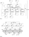
Figure 1 schematically illustrates a telecommunications network according to the present invention, having a fixed line part and a mobile (or cellular) part, and, hence, providing the possibility for user equipment or client devices to use different access technologies, wherein the telecommunications network comprises a broadband access network, and wherein a logical or physical central office point of delivery (being part of the broadband access network) is handling different access possibilities. -
Figures 2 and3 schematically illustrate a part of the telecommunications network, wherein the represented part of the telecommunications network comprises a switching fabric within a logical or physical central office point of delivery, which itself part of the broadband access network of the telecommunications network. -
Figure 4 schematically illustrates and example of a pseudo wire between at remote access node and a termination network node of the pseudo wire. - The present invention will be described with respect to particular embodiments and with reference to certain drawings but the invention is not limited thereto but only by the claims. The drawings described are only schematic and are nonlimiting. In the drawings, the size of some of the elements may be exaggerated and not drawn on scale for illustrative purposes.
- Where an indefinite or definite article is used when referring to a singular noun, e.g. "a", "an", "the", this includes a plural of that noun unless something else is specifically stated.
- Furthermore, the terms first, second, third and the like in the description and in the claims are used for distinguishing between similar elements and not necessarily for describing a sequential or chronological order. It is to be understood that the terms so used are interchangeable under appropriate circumstances and that the embodiments of the invention described herein are capable of operation in other sequences than described or illustrated herein.
- In
Figure 1 , atelecommunications network 100 according to the present invention is schematically shown, having - preferably - a fixed line part and a mobile (or cellular) part (schematically illustrated by means of base station entities 150). According to such a preferred embodiment of thetelecommunications network 100 comprising a fixed line part and a mobile (or cellular) part, it is provide for the user equipment orclient devices telecommunications network 100 of the "fixed-line-only" type, or atelecommunications network 100 of the "mobile (or cellular)-only" type is possible to be used according to the present invention. Thetelecommunications network 100 comprises at least one logical or physical central office point ofdelivery 110 that is preferably realized within a data center and that is handling different access requirements, especially different access possibilities, of theclient devices telecommunications network 100 or via thetelecommunications network 100. Theclient devices delivery 110 by means of a customerpremises equipment device 50 or by means of a customer premises equipment functionality that might be built in theclient devices -
Figures 2 and3 schematically illustrate a part of thetelecommunications network 100, wherein the represented part of thetelecommunications network 100 comprises a switchingfabric 115 within a logical or physical central office point ofdelivery 110, which itself part of thebroadband access network 120 of thetelecommunications network 100. The switchingfabric 115 comprises a plurality ofspine network nodes Figures 2 and3 , the switchingfabric 115 comprises two spine network nodes, a firstspine network node 101 and a secondspine network node 102. Furthermore, the switchingfabric 115 comprises a plurality ofleaf network nodes Figures 2 and3 , the switchingfabric 115 comprises four leaf network nodes, a firstleaf network node 201, a secondleaf network node 202, a thirdleaf network node 203, and a fourthleaf network node 204. Within the switchingfabric 115 each one of the plurality ofspine network nodes leaf network nodes broadband access network 120 comprises a plurality of (label)edge nodes Figures 2 and3 . Thespine network nodes edge nodes Figures 2 and3 , there is a 1:1 relationship between each one of thespine network nodes edge nodes - The central office point of
delivery 110 furthermore comprises a plurality ofline termination nodes service edge nodes Figures 2 and3 , the central office point ofdelivery 110 comprises two line termination nodes, a firstline termination node 301 and a secondline termination node 302, and two service edge nodes, such as, e.g. BNG (Broadband Network Gateway nodes), a firstservice edge node 401, and a secondservice edge node 402. Furthermore, thebroadband access network 120 comprises a plurality ofremote access nodes line termination nodes remote access nodes Figures 2 and3 , thebroadband access network 120 comprises two remote access nodes, a firstremote access node 501, and a secondremote access node 502. - The
spine network nodes Figures 2 and3 , each one of thespine network nodes Figures 2 and3 at each one of thespine network nodes spine network node ports 1 to 4 provide a connection to one of the leaf network nodes, i.e. port 1 (respectively of the first or the secondspine network node 101, 102) provides the connection to the firstline termination node 301,port 2 provides the connection to the secondline termination node 302, etc.; for eachspine network node spine network node 101, 102) provides a connection to one of the (label)edge nodes - Likewise, the
leaf network node Figures 2 and3 , each one of theleaf network node Figures 2 and3 at each one of theleaf network node leaf network node ports leaf network node spine network node 101,port 2 provides the connection to the secondspine network node 102; for eachleaf network node leaf network node line termination node service edge nodes -
Figure 4 schematically illustrates and example of a pseudo wire between at specific remote access node 501 (or the plurality ofremote access nodes 501, 502) and a termination network node 171 (of the pseudo wire). The pseudo wire is designated by means ofreference sign 500 and comprises three so-called segments: Afirst segment 510 spans the considered (or specific)remote access node 501 and the considered (or connected)line termination node 301; asecond segment 520 spans the considered (or connected)line termination node 301, theleaf network node 201, and thespine network node 101; athird segment 530 spans thespine network node 101 and thetermination network node 171. According to the present invention, data packets are transported (or routed) to or from the specificremote access node 501 of the plurality ofremote access nodes pseudo wire 500. Thepseudo wire 500 spans all the mentioned segments, i.e. according to the example shown inFigure 4 thefirst segment 510, thesecond segment 520, and thethird segment 530. - The
pseudo wire 500 spans the specificremote access node 501 and the switching fabric 115 (i.e. including the specificremote access node 501, the consideredline termination node 301, theleaf network node 201, and the spine network node 101). Two exemplary data packets are schematically illustrated inFigure 4 , a (first, downstream)data packet 410, and a (second, upstream)data packet 420. Bothdata packets telecommunications network 100. - Between the specific
remote access node 501 and the line termination node 301 (corresponding to thefirst segment 510 of the pseudo wire 500), a first header label information 411 (reading "321" in the exemplary embodiment ofFigure 4 ) is used for the (first) data packet 410 (that is received by the specific remote access node 501) and a second header label information 421 (reading "123" in the exemplary embodiment ofFigure 4 ) is used for the (second) data packet 420 (sent from the specific remote access node 501). - Between the
line termination node 301 and the spine network node 101 - i.e. within the central office point of delivery and across the switching fabric (corresponding to thesecond segment 520 of the pseudo wire 500) -, a third header label information 412 (reading "301" in the exemplary embodiment ofFigure 4 ) is used for the (first)data packet 410 and a fourth header label information 422 (reading "101" in the exemplary embodiment ofFigure 4 ) is used for the (second)data packet 420. - Between the
spine network node 101 and the termination network node 171 (corresponding to thethird segment 530 of the pseudo wire 500), at least a fifth header label information 413 (reading "987" in the exemplary embodiment ofFigure 4 ) is used for the (first)data packet 410 and a sixth header label information 423 (reading "789" in the exemplary embodiment ofFigure 4 ) is used for the (second) data packet 420.The use of thepseudo wire 500 additionally comprises using a seventh header label information 414 (reading "654" in the exemplary embodiment ofFigure 4 ) for the (first)data packet 410 to be received by the specificremote access node 501 and using an eighth header label information 424 (reading "456" in the exemplary embodiment ofFigure 4 ) for the (second)data packet 420 sent from the specificremote access node 501. - As shown in Figure, the termination network node is located outside of the central office point of
delivery 110, wherein "located outside of the central office point ofdelivery 110" either means in the "northbound" direction - i.e. towards a hierarchically higher level such as a label edge router towards the backbone or core network of the telecommunications network 100 -, or in the "southbound" direction - i.e. towards a hierarchically lower level such as, e.g., another remote access node (compared to the specific remote access node 501). - Furthermore, according to the present invention, the
broadband access network 120, especially the central office point ofdelivery 110 or the switchingfabric 115 comprises acontroller node 160 and/or avirtual router instance 161, especially on thecontroller node 160, wherein the generation and/or the establishment of thepseudo wire 500 is controlled by thecontroller node 160 and/or by the virtual router instance 161 (especially of the controller node 160). Especially, the method comprises a first step such that, in case that the (first)data packet 410 is to be received by the specificremote access node 501, thecontroller node 160 and/or thevirtual router instance 161 assigns the firstheader label information 411 and/or the thirdheader label information 412 to thepseudo wire 500, and in case that the (second)data packet 420 is to be sent from the specificremote access node 501, thecontroller node 160 and/or thevirtual router instance 161 assigns the secondheader label information 421 and/or the fourthheader label information 422 to thesecond segment 520 of thepseudo wire 500. In a second step, subsequent to the first step, the (first)data packet 410 is received by the specificremote access node 501 or the (second)data packet 420 is sent from the specific remote access node (501). - According to the present invention, MPLS (Multiprotocol Label Switching) segment routing is used to forward data packets across the switching fabric. In segment routing, there are two different kinds of MPLS labels known as segment identifiers (SID):
- -- Prefix SID which represents an IP prefix (or subnet) and is unique within the switching fabric; the node SID is a special prefix SID which represents the node itself (i.e. the loopback prefix),
- -- Adjacency SID (adj-SID) which represents a link and is only locally significant to the node attached to the link.
- In order to provide MPLS transport between any two nodes within the switching fabric, a label switched path (LSP) needs to be setup. With segment routing, the nodes within the switching fabric only need to know the node SID of all other nodes to establish LSPs to any potential destination. As the node SID is unique, pushing the node SID on top of a packet results in forwarding the packet through the switching fabric until it reaches the destination node. The destination node removes (pops) the node SID and inspects the remaining packet.
- According to the present invention, an overlay of the switching fabric is provided by means of using the pseudo wire 500 (or by means of using a plurality of such pseudo wires). The pseudo wire overlays are especially used for subscriber traffic between line termination nodes (such as OLTs) and the service edge (especially of different central office points of delivery), especially service edge nodes, i.e. in order to transport frames from the line termination nodes (or OLTs) to the (virtual) BNG (Broadband Network Gateway) and, especially, in order to avoid scaling issues with VLAN stacking. A pseudo wire provides a transparent layer connection between two endpoints. The pseudo wire terminates for example on the line termination node (e.g. an OLT) and the (v)BNG itself (or even multiple pseudo wires; each per access port) and is represented by a pseudo wire label (i.e. the fifth to eighth header label information) which is only known to the endpoints. There is a N:M mapping between line termination nodes (or OLTs) and (v)BNGs, i.e. the pseudo wires, per node or per access node port, configured on a single line termination node typically terminate on multiple (v)BNG-nodes (this can be done either physically or logically or in a grouped manner). If a line termination node receives a frame (or a data packet) from the PON tree (passive optical network tree), it maps the VID (access port) to a pseudowire and pushes the pseudowire label on top of the packet. In addition - depending on the remote pseudo wire termination point (i.e. the termination network node) - it also pushes a prefix SID label representing the (v)BNG and forwards the packet to the leaf switch. Because the line termination node (or OLT) should not participate in dynamic signaling, the prefix SID labels to reach nodes within the central office point of
delivery 110 as well as the pseudo wire service label are configured via a southbound API by a controller instance (i.e. thecontroller node 160 and/or the virtual router instance 161). The leaf network node processes the topmost label which is the prefix SID label for the destination node. Based on this label, the frame (or data packet) is either locally switched (in case the vBNG is connected to the same leaf switch as the line termination node) or usually forwarded to one of the spine switches. As there are two spine network nodes with ECMP paths to the destination, the frames (or data packets) are load-balanced based on some kind of hashing. Similar to the ingress leaf network node, the spine network node and egress leaf network node will forward the data packet based on the topmost node SID label which remains unchanged. The (v)BNG pops the node SID label which represents itself and processes the PW label. It decapsulates the PPPoE frame executes the subscriber specific operations. - It is especially advantageous that there is no restriction in switch ports within the central office point of
delivery 110, i.e. the same dataplane can be used to hand over wholesale traffic to another internet service provider on a port on the spine network node as every switching fabric network node has a unique node label and therefore qualifies as a termination point for the pseudo wire. - For some applications, e.g.wholesale or business access, it might be necessary to setup a pseudo wire between the line termination node (or OLT) and a network node which is outside the central office point of delivery. As the line termination node should not be included in dynamic routing and signaling, a "pseudo wire proxy" running on the spine network node is introduced. The pseudo wire proxy re-uses the concept of multisegment pseudo wire described in RFC5659 -where the pseudo wire proxy is called pseudo wire switching provider edge (PW S-PE). As in the previous case, relevant frames arriving on the line termination node (or OLT) from a PON tree are matched and two labels are pushed on top of the frame, the inner label representing the pseudo wire label and outer label representing the destination which is the one of the spine network nodes. According to an alternative embodiment of the present invention, a kind of any cast label is used for both spine network nodes, which means that nodes within the central office point of
delivery 110 that connecting to the outside world can use any of the spine network nodes because they have the same forwarding table. This concept helps to move the service from one spine network node to another in case of node or link failure. As the line termination node (or OLT) does not take part in dynamic signaling, a virtual routing process performs the signaling with the remote pseudo wire termination point. It therefore uses eBGP-LU to establish a transport path to the remote device and in addition uses LDP or BGP to signal the pseudo wire. The spine network node acts as a pseudo wire switching device, i.e. it has to swap the pseudo wire label which was pushed by the line termination node (or OLT) to the pseudo wire label learned from the remote pseudo wire termination point. In addition, it has to push the transport label towards the backbone forwarding the frame to the connected label edge router. The pseudo wire label used to communicate within the central office point ofdelivery 110 is configured by thecontroller node 160. - According to the present invention, the
pseudo wires 500 span also the remote access node (or MSAN device) to the line termination node, i.e. the remote access node is a termination point of thepseudo wires 500. The basic concept is to use amulti-segment pseudowire 500 with the above mentioned three segments. - For sake of simplicity, the routing process exchanging information with the backbone is hosted on the controller. Without limiting the basic concept, it can be moved to the spine switch if necessary.
- On the (v)BNG, the IP packet resulting from PPP session termination needs to be forwarded to the IP backbone. In the simplest way, this is done via two default routes pointing towards the spine switches.
- Therefore, the (v)BNG pushes two labels on top of the IP packets and forwards those packets to the leaf switch it is connected to. The outer MPLS label represents the prefix SID of the egress spine switch, while the inner label represents the routing context (e.g. the global IP routing table). In this document this label is called the table ID label (TID). In general, the inner label can also be used to represent a specific VPN context. The leaf switch only processes the topmost label and forwards the frame to one of the spine switches.
- The spine switch pops the topmost label because it is his own node SID label and performs a lookup on the second label (TID label). The TID label represents the uplink to the IP backbone, i.e. in the simplest case there is only one TID label which corresponds to the uplink interface. If there are multiple uplink interfaces, multiple different TID labels might be used for TE purposes. In case MPLS L3VPNs are implemented on the POD, additional TID labels might be allocated to the different L3VPNs. In this scenario, it might be necessary not only to pop the TID label but also to rewrite the frame header with a VLAN ID.
Claims (8)
- A method for the use of a switching fabric (115) within a central office point of delivery (110) of a broadband access network (120) of a telecommunications network (100),wherein the switching fabric (115) comprises a plurality of spine network nodes (101, 102) and a plurality of leaf network nodes (201, 202, 203, 204), wherein - within the switching fabric (115) considered - each one of the plurality of spine network nodes (101, 102) is connected with each one of the plurality of leaf network nodes (201, 202, 203, 204),wherein the central office point of delivery (110) further comprises a plurality of line termination nodes (301, 302) and/or service edge nodes (401, 402), and wherein the broadband access network (120) comprises a plurality of remote access nodes (501, 502) such that each one of the plurality of line termination nodes (301, 302) is connected to at least one of the plurality of remote access nodes (501, 502),wherein the telecommunications network (100) furthermore comprises a plurality of edge nodes (171, 172) such that each one of the plurality of spine network nodes (101, 102) is connected to at least one of the plurality of edge nodes (171, 172),characterized in that in order to transport data packets (410, 420) to or from a specific remote access node (501) of the plurality of remote access nodes (501, 502), a multi protocol label switching, MPLS, based pseudo wire (500) is used as service overlay to a MPLS segment routing based transport underlay, wherein the pseudo wire (500) comprises a first segment (510) extending from the specific remote access node (501) to a line termination node (301), a second segment (520) from the line termination node (301) to a spine network node (101), and a third segment (530) from the spine network node (101) to a termination point outside of the central office point of delivery, wherein the use of the pseudo wire (500) comprises using a first header label information (411) for a data packet (410) received by the specific remote access node (501) and using a second header label information (421) for a data packet (420) sent from the specific remote access node (501),wherein, in order to transport the data packets (410, 420) across the switching fabric (115), MPLS segment routing of the data packets (410, 420) is used involving a third header label information (412) for the data packet (410) received by the specific remote access node (501) and using a fourth header label information (422) for the data packet (420) sent from the specific remote access node (501), wherein the use of the pseudo wire (500) comprises using at least a fifth header label information (413) for the data packet (410) to be received by the specific remote access node (501) and using a sixth header label information (423) for the data packet (420) sent from the specific remote access node (501), wherein the use of the pseudo wire (500) additionally comprises using a seventh header label information (414) for the data packet (410) to be received by the specific remote access node (501) and using an eighth header label information (424) for the data packet (420) sent from the specific remote access node (501),wherein for the data packet (410) to be received by the specific remote access node and sent from the termination point outside of the central office point of delivery (110) towards the specific remote access node (501), the spine network node (101) removes the fifth and seventh header label information (413, 414) and adds the first and third header label information (411, 412) to the data packet (410), while the line termination node (301) removes the third header label information (412) from the data packet (410), andwherein for the data packet (420) sent from the specific remote access node (501) towards the termination point outside of the central office point of delivery (110), the line termination node (301) adds the fourth header label information (422) to the data packet (420), while the spine network node (101) removes the second and fourth header label information (421, 422) and adds the eighth and sixth header label information (424, 423).
- The method according to claim 1, wherein the broadband access network (120), the central office point of delivery (110) or the switching fabric (115) comprises a controller node (160) and/or a virtual router instance (161), wherein the method comprises the following steps:-- in a first step, in the case of the data packet (410) to be received by the specific remote access node (501), the controller node (160) and/or the virtual router instance (161) assigns the first header label information (411) and/or the third header label information (412) to the pseudo wire (500), and in the case of the data packet (420) sent from the specific remote access node (501), the controller node (160) and/or the virtual router instance (161) assigns the second header label information (421) and/or the fourth header label information (422) to the pseudo wire (500),-- in a second step, subsequent to the first step, the data packet (410) is received by the specific remote access node (501) or the data packet (420) is sent from the specific remote access node (501).
- The method according to claim 2, wherein the controller node (160) and/or the virtual router instance (161) is hosted by one or a plurality of spine nodes (101, 102).
- The method according to one of the preceding claims, wherein segment identifiers are used as the third and fourth header label information (412, 422) within the switching fabric (115), wherein the segment identifiers are unique identifiers within the switching fabric (115).
- A logical or physical central office point of delivery (110) for the use of a switching fabric (115) within the central office point of delivery (110) of a broadband access network (120) of a telecommunications network (100), wherein the switching fabric (115) comprises a plurality of spine network nodes (101, 102) and a plurality of leaf network nodes (201, 202, 203, 204), wherein - within the switching fabric (115) considered - each one of the plurality of spine network nodes (101, 102) is connected with each one of the plurality of leaf network nodes (201, 202, 203, 204),wherein the central office point of delivery (110) further comprises a plurality of line termination nodes (301, 302) and/or service edge nodes (401, 402), and wherein the broadband access network (120) comprises a plurality of remote access nodes (501, 502) such that each one of the plurality of line termination nodes (301, 302) is connected to at least one of the plurality of remote access nodes (501, 502),wherein the telecommunications network (100) furthermore comprises a plurality of edge nodes (171, 172) such that each one of the plurality of spine network nodes (101, 102) is connected to at least one of the plurality of edge nodes (171, 172),wherein the central office point of delivery (110) is characterized in being configured such that, in order to transport data packets (410, 420) to or from a specific remote access node (501) of the plurality of remote access nodes (501, 502), a multi protocol label switching, MPLS, based pseudo wire (500) is used as service overlay to a MPLS segment routing based transport underlay,wherein the pseudo wire (500) comprises a first segment (510) extending from the specific remote access node (501) to a line termination node (301), a second segment (520) from the line termination node (301) to a spine network node (101), and a third segment (530) from the spine network node (101) to a termination point outside of the central office point of delivery, wherein the use of the pseudo wire (500) comprises using a first header label information (411) for a data packet (410) received by the specific remote access node (501) and using a second header label information (421) for a data packet (420) sent from the specific remote access node (501),wherein, in order to transport the data packets (410, 420) across the switching fabric (115), MPLS segment routing of the data packets (410, 420) is used involving a third header label information (412) for the data packet (410) received by the specific remote access node (501) and using a fourth header label information (422) for the data packet (420) sent from the specific remote access node (501),wherein the use of the pseudo wire (500) comprises using at least a fifth header label information (413) for the data packet (410) to be received by the specific remote access node (501) and using a sixth header label information (423) for the data packet (420) sent from the specific remote access node (501), wherein the use of the pseudo wire (500) additionally comprises using a seventh header label information (414) for the data packet (410) to be received by the specific remote access node (501) and using an eighth header label information (424) for the data packet (420) sent from the specific remote access node (501),wherein for the data packet (410) to be received by the specific remote access node and sent from the termination point outside of the central office point of delivery (110) towards the specific remote access node (501), the spine network node (101) is configured to remove the fifth and seventh header label information (413, 414) and to add the first and third header label information (411, 412) to the data packet (410), while the line termination node (301) is configured to remove the third header label information (412) from the data packet (410), andwherein for the data packet (420) sent from the specific remote access node (501) towards the termination point outside of the central office point of delivery (110), the line termination node (301) is configured to add the fourth header label information (422) to the data packet (420), while the spine network node (101) is configured to remove the second and fourth header label information (421, 422) and to add the eighth and sixth header label information (424, 423).
- A telecommunications network (100) for the use of a switching fabric (115) within a central office point of delivery (110), wherein the telecommunication network (100) comprises the logical or physical central office point of delivery (110) according to claim 5.
- A program comprising a computer readable program code which, when executed on a computer and/or on a logical or physical central office point of delivery (110) and/or on a network node of a switching fabric (115) within a central office point of delivery (110), or in part on a logical or physical central office point of delivery (110) and/or in part on a network node of a switching fabric (115) within a central office point of delivery (110), causes the computer and/or the logical or physical central office point of delivery (110) and/or the network node of a switching fabric (115) within a central office point of delivery (110) to perform a method according one of claims 1 to 4.
- A computer-readable storage medium for the use of a switching fabric (115) within a central office point of delivery (110) of a broadband access network (120) of a telecommunications network (100), the computer-readable storage medium comprising program code which, when executed on a computer and/or on a logical or physical central office point of delivery (110) and/or on a network node of a switching fabric (115) within a central office point of delivery (110), or in part on a logical or physical central office point of delivery (110) and/or in part on a network node of a switching fabric (115) within a central office point of delivery (110), causes the computer and/or the logical or physical central office point of delivery (110) and/or the network node of a switching fabric (115) within a central office point of delivery (110) to perform a method according one of claims 1 to 4.
Applications Claiming Priority (2)
| Application Number | Priority Date | Filing Date | Title |
|---|---|---|---|
| EP17156255 | 2017-02-15 | ||
| PCT/EP2018/052971 WO2018149702A1 (en) | 2017-02-15 | 2018-02-06 | Method for enhanced use of a switching fabric within a central office point of delivery of a broadband access network of a telecommunications network |
Publications (2)
| Publication Number | Publication Date |
|---|---|
| EP3583752A1 EP3583752A1 (en) | 2019-12-25 |
| EP3583752B1 true EP3583752B1 (en) | 2024-11-27 |
Family
ID=58046576
Family Applications (1)
| Application Number | Title | Priority Date | Filing Date |
|---|---|---|---|
| EP18702712.3A Active EP3583752B1 (en) | 2017-02-15 | 2018-02-06 | Method for enhanced use of a switching fabric within a central office point of delivery of a broadband access network of a telecommunications network |
Country Status (5)
| Country | Link |
|---|---|
| US (1) | US11108688B2 (en) |
| EP (1) | EP3583752B1 (en) |
| CN (1) | CN110199504B (en) |
| ES (1) | ES2996708T3 (en) |
| WO (1) | WO2018149702A1 (en) |
Families Citing this family (4)
| Publication number | Priority date | Publication date | Assignee | Title |
|---|---|---|---|---|
| ES2970255T3 (en) | 2020-02-28 | 2024-05-27 | Deutsche Telekom Ag | Procedure for improved operation of a broadband access network of a telecommunications network and/or for improved and/or more energy-efficient operation of the broadband access network, broadband access network or telecommunications network, and computer-readable system, program and medium. |
| EP4092966A1 (en) * | 2021-05-21 | 2022-11-23 | Deutsche Telekom AG | Method for operating a broadband access network of a telecommunications network comprising at least one central office point of delivery, system, broadband access network or telecommunications network, central office point of delivery cluster, program and computer-readable medium |
| ES2970528T3 (en) * | 2021-06-18 | 2024-05-29 | Deutsche Telekom Ag | Method for routing data packets, between a plurality of network nodes of a telecommunications network, while taking into account the energy intensity with respect to the transmission of such data packets, telecommunications network or network node, program and computer-readable medium |
| EP4161028B1 (en) * | 2021-09-29 | 2024-09-25 | Deutsche Telekom AG | Method for operating a broadband access network of a telecommunications network comprising a plurality of central office points of delivery, broadband access network or telecommunications network, central office point of delivery, system, program and computer-readable medium |
Family Cites Families (5)
| Publication number | Priority date | Publication date | Assignee | Title |
|---|---|---|---|---|
| CN101931548B (en) | 2009-06-24 | 2012-09-19 | 华为技术有限公司 | Method, apparatus and system for label management of access network |
| CN101645836B (en) * | 2009-08-25 | 2012-04-18 | 杭州华三通信技术有限公司 | Packet transmission method and device in multi-protocol label switching network |
| US8553533B2 (en) | 2010-12-10 | 2013-10-08 | Cisco Technology, Inc. | System and method for providing improved failover performance for pseudowires |
| US9100285B1 (en) * | 2012-12-18 | 2015-08-04 | Juniper Networks, Inc. | Dynamic control channel establishment for software-defined networks having centralized control |
| US10097372B2 (en) * | 2014-01-09 | 2018-10-09 | Ciena Corporation | Method for resource optimized network virtualization overlay transport in virtualized data center environments |
-
2018
- 2018-02-06 WO PCT/EP2018/052971 patent/WO2018149702A1/en not_active Ceased
- 2018-02-06 US US16/479,978 patent/US11108688B2/en active Active
- 2018-02-06 EP EP18702712.3A patent/EP3583752B1/en active Active
- 2018-02-06 CN CN201880007518.4A patent/CN110199504B/en active Active
- 2018-02-06 ES ES18702712T patent/ES2996708T3/en active Active
Non-Patent Citations (1)
| Title |
|---|
| LI R ZHENG HUAWEI TECHNOLOGIES A FARREL OLD DOG CONSULTING H: "Multi-Segment Pseudowires in Passive Optical Networks; rfc6456.txt", MULTI-SEGMENT PSEUDOWIRES IN PASSIVE OPTICAL NETWORKS; RFC6456.TXT, INTERNET ENGINEERING TASK FORCE, IETF; STANDARD, INTERNET SOCIETY (ISOC) 4, RUE DES FALAISES CH- 1205 GENEVA, SWITZERLAND, 29 November 2011 (2011-11-29), pages 1 - 12, XP015081369 * |
Also Published As
| Publication number | Publication date |
|---|---|
| ES2996708T3 (en) | 2025-02-13 |
| US20190342206A1 (en) | 2019-11-07 |
| WO2018149702A1 (en) | 2018-08-23 |
| CN110199504B (en) | 2021-12-28 |
| US11108688B2 (en) | 2021-08-31 |
| CN110199504A (en) | 2019-09-03 |
| EP3583752A1 (en) | 2019-12-25 |
Similar Documents
| Publication | Publication Date | Title |
|---|---|---|
| US7269135B2 (en) | Methods and systems for providing redundant connectivity across a network using a tunneling protocol | |
| EP1713197B1 (en) | A method for implementing the virtual leased line | |
| EP1816796B1 (en) | Bi-directional forwarding in ethernet-based service domains over networks | |
| US20050190757A1 (en) | Interworking between Ethernet and non-Ethernet customer sites for VPLS | |
| EP2536068A1 (en) | Virtual subscriber management | |
| MX2007008112A (en) | Connection-oriented communications scheme for connection-less communications traffic. | |
| EP1916812A1 (en) | Method and device for fast convergence | |
| US20060062218A1 (en) | Method for establishing session in label switch network and label switch node | |
| US8837521B2 (en) | Ethernet network within MPLS network | |
| CN101877677B (en) | Tunnel switching method and system for multi-protocol label switching services | |
| US11108688B2 (en) | Enhanced use of a switching fabric within a central office point of delivery of a broadband access network of a telecommunications network | |
| US7899061B2 (en) | Access device and service transmission method | |
| CN100525227C (en) | Method for realizing integrated service access by access network | |
| EP2033377B1 (en) | Forced medium access control (MAC) learning in bridged ethernet networks | |
| US20060203820A1 (en) | Method and system for communicating and isolating packetized data through a plurality of last-mile carriers to form a multi-node intranet | |
| CN101232460A (en) | Method for access network to realize synthesis business access | |
| US7797444B2 (en) | Data transfer apparatus and data transfer system | |
| US11063782B2 (en) | Access network with remote access servers | |
| CN112737951B (en) | End-to-end SR control method, system and readable storage medium in public and private network mixed scene | |
| Vaez-Ghaemi | Next-Generation Packet-Based Transport Networks (PTN) | |
| EP2093952A1 (en) | Method and device for processing data in an MPLS domain and communication system comprising such device | |
| CN102195852B (en) | Method and BEB (Backbone Edge Bridge) equipment for realizing user leased-line connection in PBB (Provider Backbone Bridge) network | |
| CN101379779A (en) | Method for routing connections in a packet-switched communication network | |
| KR20070061933A (en) | Apparatus and method for providing point-to-point service between subscribers using MPS VP |
Legal Events
| Date | Code | Title | Description |
|---|---|---|---|
| STAA | Information on the status of an ep patent application or granted ep patent |
Free format text: STATUS: UNKNOWN |
|
| STAA | Information on the status of an ep patent application or granted ep patent |
Free format text: STATUS: THE INTERNATIONAL PUBLICATION HAS BEEN MADE |
|
| PUAI | Public reference made under article 153(3) epc to a published international application that has entered the european phase |
Free format text: ORIGINAL CODE: 0009012 |
|
| STAA | Information on the status of an ep patent application or granted ep patent |
Free format text: STATUS: REQUEST FOR EXAMINATION WAS MADE |
|
| 17P | Request for examination filed |
Effective date: 20190916 |
|
| AK | Designated contracting states |
Kind code of ref document: A1 Designated state(s): AL AT BE BG CH CY CZ DE DK EE ES FI FR GB GR HR HU IE IS IT LI LT LU LV MC MK MT NL NO PL PT RO RS SE SI SK SM TR |
|
| AX | Request for extension of the european patent |
Extension state: BA ME |
|
| DAV | Request for validation of the european patent (deleted) | ||
| DAX | Request for extension of the european patent (deleted) | ||
| STAA | Information on the status of an ep patent application or granted ep patent |
Free format text: STATUS: EXAMINATION IS IN PROGRESS |
|
| 17Q | First examination report despatched |
Effective date: 20210120 |
|
| REG | Reference to a national code |
Ref country code: DE Ref legal event code: R079 Ref document number: 602018076922 Country of ref document: DE Free format text: PREVIOUS MAIN CLASS: H04L0012721000 Ipc: H04L0045000000 |
|
| GRAP | Despatch of communication of intention to grant a patent |
Free format text: ORIGINAL CODE: EPIDOSNIGR1 |
|
| STAA | Information on the status of an ep patent application or granted ep patent |
Free format text: STATUS: GRANT OF PATENT IS INTENDED |
|
| RIC1 | Information provided on ipc code assigned before grant |
Ipc: H04L 45/48 20220101ALI20240621BHEP Ipc: H04L 45/00 20220101AFI20240621BHEP |
|
| INTG | Intention to grant announced |
Effective date: 20240712 |
|
| GRAS | Grant fee paid |
Free format text: ORIGINAL CODE: EPIDOSNIGR3 |
|
| GRAA | (expected) grant |
Free format text: ORIGINAL CODE: 0009210 |
|
| STAA | Information on the status of an ep patent application or granted ep patent |
Free format text: STATUS: THE PATENT HAS BEEN GRANTED |
|
| AK | Designated contracting states |
Kind code of ref document: B1 Designated state(s): AL AT BE BG CH CY CZ DE DK EE ES FI FR GB GR HR HU IE IS IT LI LT LU LV MC MK MT NL NO PL PT RO RS SE SI SK SM TR |
|
| REG | Reference to a national code |
Ref country code: GB Ref legal event code: FG4D |
|
| REG | Reference to a national code |
Ref country code: CH Ref legal event code: EP |
|
| REG | Reference to a national code |
Ref country code: IE Ref legal event code: FG4D |
|
| REG | Reference to a national code |
Ref country code: DE Ref legal event code: R096 Ref document number: 602018076922 Country of ref document: DE |
|
| REG | Reference to a national code |
Ref country code: ES Ref legal event code: FG2A Ref document number: 2996708 Country of ref document: ES Kind code of ref document: T3 Effective date: 20250213 |
|
| REG | Reference to a national code |
Ref country code: LT Ref legal event code: MG9D |
|
| REG | Reference to a national code |
Ref country code: NL Ref legal event code: MP Effective date: 20241127 |
|
| PG25 | Lapsed in a contracting state [announced via postgrant information from national office to epo] |
Ref country code: HR Free format text: LAPSE BECAUSE OF FAILURE TO SUBMIT A TRANSLATION OF THE DESCRIPTION OR TO PAY THE FEE WITHIN THE PRESCRIBED TIME-LIMIT Effective date: 20241127 Ref country code: IS Free format text: LAPSE BECAUSE OF FAILURE TO SUBMIT A TRANSLATION OF THE DESCRIPTION OR TO PAY THE FEE WITHIN THE PRESCRIBED TIME-LIMIT Effective date: 20250327 Ref country code: PT Free format text: LAPSE BECAUSE OF FAILURE TO SUBMIT A TRANSLATION OF THE DESCRIPTION OR TO PAY THE FEE WITHIN THE PRESCRIBED TIME-LIMIT Effective date: 20250327 |
|
| PG25 | Lapsed in a contracting state [announced via postgrant information from national office to epo] |
Ref country code: FI Free format text: LAPSE BECAUSE OF FAILURE TO SUBMIT A TRANSLATION OF THE DESCRIPTION OR TO PAY THE FEE WITHIN THE PRESCRIBED TIME-LIMIT Effective date: 20241127 Ref country code: NL Free format text: LAPSE BECAUSE OF FAILURE TO SUBMIT A TRANSLATION OF THE DESCRIPTION OR TO PAY THE FEE WITHIN THE PRESCRIBED TIME-LIMIT Effective date: 20241127 |
|
| REG | Reference to a national code |
Ref country code: AT Ref legal event code: MK05 Ref document number: 1746820 Country of ref document: AT Kind code of ref document: T Effective date: 20241127 |
|
| PG25 | Lapsed in a contracting state [announced via postgrant information from national office to epo] |
Ref country code: BG Free format text: LAPSE BECAUSE OF FAILURE TO SUBMIT A TRANSLATION OF THE DESCRIPTION OR TO PAY THE FEE WITHIN THE PRESCRIBED TIME-LIMIT Effective date: 20241127 |
|
| PG25 | Lapsed in a contracting state [announced via postgrant information from national office to epo] |
Ref country code: NO Free format text: LAPSE BECAUSE OF FAILURE TO SUBMIT A TRANSLATION OF THE DESCRIPTION OR TO PAY THE FEE WITHIN THE PRESCRIBED TIME-LIMIT Effective date: 20250227 |
|
| PG25 | Lapsed in a contracting state [announced via postgrant information from national office to epo] |
Ref country code: LV Free format text: LAPSE BECAUSE OF FAILURE TO SUBMIT A TRANSLATION OF THE DESCRIPTION OR TO PAY THE FEE WITHIN THE PRESCRIBED TIME-LIMIT Effective date: 20241127 Ref country code: AT Free format text: LAPSE BECAUSE OF FAILURE TO SUBMIT A TRANSLATION OF THE DESCRIPTION OR TO PAY THE FEE WITHIN THE PRESCRIBED TIME-LIMIT Effective date: 20241127 Ref country code: GR Free format text: LAPSE BECAUSE OF FAILURE TO SUBMIT A TRANSLATION OF THE DESCRIPTION OR TO PAY THE FEE WITHIN THE PRESCRIBED TIME-LIMIT Effective date: 20250228 |
|
| PG25 | Lapsed in a contracting state [announced via postgrant information from national office to epo] |
Ref country code: PL Free format text: LAPSE BECAUSE OF FAILURE TO SUBMIT A TRANSLATION OF THE DESCRIPTION OR TO PAY THE FEE WITHIN THE PRESCRIBED TIME-LIMIT Effective date: 20241127 |
|
| PG25 | Lapsed in a contracting state [announced via postgrant information from national office to epo] |
Ref country code: RS Free format text: LAPSE BECAUSE OF FAILURE TO SUBMIT A TRANSLATION OF THE DESCRIPTION OR TO PAY THE FEE WITHIN THE PRESCRIBED TIME-LIMIT Effective date: 20250227 |
|
| PG25 | Lapsed in a contracting state [announced via postgrant information from national office to epo] |
Ref country code: SM Free format text: LAPSE BECAUSE OF FAILURE TO SUBMIT A TRANSLATION OF THE DESCRIPTION OR TO PAY THE FEE WITHIN THE PRESCRIBED TIME-LIMIT Effective date: 20241127 |
|
| PG25 | Lapsed in a contracting state [announced via postgrant information from national office to epo] |
Ref country code: DK Free format text: LAPSE BECAUSE OF FAILURE TO SUBMIT A TRANSLATION OF THE DESCRIPTION OR TO PAY THE FEE WITHIN THE PRESCRIBED TIME-LIMIT Effective date: 20241127 |
|
| PG25 | Lapsed in a contracting state [announced via postgrant information from national office to epo] |
Ref country code: EE Free format text: LAPSE BECAUSE OF FAILURE TO SUBMIT A TRANSLATION OF THE DESCRIPTION OR TO PAY THE FEE WITHIN THE PRESCRIBED TIME-LIMIT Effective date: 20241127 |
|
| PG25 | Lapsed in a contracting state [announced via postgrant information from national office to epo] |
Ref country code: RO Free format text: LAPSE BECAUSE OF FAILURE TO SUBMIT A TRANSLATION OF THE DESCRIPTION OR TO PAY THE FEE WITHIN THE PRESCRIBED TIME-LIMIT Effective date: 20241127 |
|
| PG25 | Lapsed in a contracting state [announced via postgrant information from national office to epo] |
Ref country code: SK Free format text: LAPSE BECAUSE OF FAILURE TO SUBMIT A TRANSLATION OF THE DESCRIPTION OR TO PAY THE FEE WITHIN THE PRESCRIBED TIME-LIMIT Effective date: 20241127 |
|
| PG25 | Lapsed in a contracting state [announced via postgrant information from national office to epo] |
Ref country code: CZ Free format text: LAPSE BECAUSE OF FAILURE TO SUBMIT A TRANSLATION OF THE DESCRIPTION OR TO PAY THE FEE WITHIN THE PRESCRIBED TIME-LIMIT Effective date: 20241127 |
|
| REG | Reference to a national code |
Ref country code: DE Ref legal event code: R097 Ref document number: 602018076922 Country of ref document: DE |
|
| PG25 | Lapsed in a contracting state [announced via postgrant information from national office to epo] |
Ref country code: SE Free format text: LAPSE BECAUSE OF FAILURE TO SUBMIT A TRANSLATION OF THE DESCRIPTION OR TO PAY THE FEE WITHIN THE PRESCRIBED TIME-LIMIT Effective date: 20241127 |
|
| PG25 | Lapsed in a contracting state [announced via postgrant information from national office to epo] |
Ref country code: MC Free format text: LAPSE BECAUSE OF FAILURE TO SUBMIT A TRANSLATION OF THE DESCRIPTION OR TO PAY THE FEE WITHIN THE PRESCRIBED TIME-LIMIT Effective date: 20241127 |
|
| REG | Reference to a national code |
Ref country code: CH Ref legal event code: PL |
|
| PLBE | No opposition filed within time limit |
Free format text: ORIGINAL CODE: 0009261 |
|
| STAA | Information on the status of an ep patent application or granted ep patent |
Free format text: STATUS: NO OPPOSITION FILED WITHIN TIME LIMIT |
|
| PG25 | Lapsed in a contracting state [announced via postgrant information from national office to epo] |
Ref country code: LU Free format text: LAPSE BECAUSE OF NON-PAYMENT OF DUE FEES Effective date: 20250206 |
|
| PG25 | Lapsed in a contracting state [announced via postgrant information from national office to epo] |
Ref country code: CH Free format text: LAPSE BECAUSE OF NON-PAYMENT OF DUE FEES Effective date: 20250228 |
|
| 26N | No opposition filed |
Effective date: 20250828 |
|
| REG | Reference to a national code |
Ref country code: BE Ref legal event code: MM Effective date: 20250228 |
|
| PG25 | Lapsed in a contracting state [announced via postgrant information from national office to epo] |
Ref country code: BE Free format text: LAPSE BECAUSE OF NON-PAYMENT OF DUE FEES Effective date: 20250228 |
|
| PG25 | Lapsed in a contracting state [announced via postgrant information from national office to epo] |
Ref country code: IE Free format text: LAPSE BECAUSE OF NON-PAYMENT OF DUE FEES Effective date: 20250206 |
|
| PGFP | Annual fee paid to national office [announced via postgrant information from national office to epo] |
Ref country code: GB Payment date: 20260219 Year of fee payment: 9 |
|
| PGFP | Annual fee paid to national office [announced via postgrant information from national office to epo] |
Ref country code: ES Payment date: 20260319 Year of fee payment: 9 |
|
| PGFP | Annual fee paid to national office [announced via postgrant information from national office to epo] |
Ref country code: DE Payment date: 20260217 Year of fee payment: 9 |
|
| PGFP | Annual fee paid to national office [announced via postgrant information from national office to epo] |
Ref country code: IT Payment date: 20260227 Year of fee payment: 9 |
|
| PGFP | Annual fee paid to national office [announced via postgrant information from national office to epo] |
Ref country code: FR Payment date: 20260223 Year of fee payment: 9 |
|
| PG25 | Lapsed in a contracting state [announced via postgrant information from national office to epo] |
Ref country code: CY Free format text: LAPSE BECAUSE OF FAILURE TO SUBMIT A TRANSLATION OF THE DESCRIPTION OR TO PAY THE FEE WITHIN THE PRESCRIBED TIME-LIMIT Effective date: 20241127 |
|
| PG25 | Lapsed in a contracting state [announced via postgrant information from national office to epo] |
Ref country code: TR Free format text: LAPSE BECAUSE OF FAILURE TO SUBMIT A TRANSLATION OF THE DESCRIPTION OR TO PAY THE FEE WITHIN THE PRESCRIBED TIME-LIMIT Effective date: 20241127 |
|
| PG25 | Lapsed in a contracting state [announced via postgrant information from national office to epo] |
Ref country code: LT Free format text: LAPSE BECAUSE OF FAILURE TO SUBMIT A TRANSLATION OF THE DESCRIPTION OR TO PAY THE FEE WITHIN THE PRESCRIBED TIME-LIMIT Effective date: 20241127 |