EP3583647B1 - Method for detecting and lessening fuel starvation in fuel cell systems - Google Patents
Method for detecting and lessening fuel starvation in fuel cell systems Download PDFInfo
- Publication number
- EP3583647B1 EP3583647B1 EP18707407.5A EP18707407A EP3583647B1 EP 3583647 B1 EP3583647 B1 EP 3583647B1 EP 18707407 A EP18707407 A EP 18707407A EP 3583647 B1 EP3583647 B1 EP 3583647B1
- Authority
- EP
- European Patent Office
- Prior art keywords
- fuel cell
- fuel
- outlet
- regulating apparatus
- anode
- Prior art date
- Legal status (The legal status is an assumption and is not a legal conclusion. Google has not performed a legal analysis and makes no representation as to the accuracy of the status listed.)
- Active
Links
Images


Classifications
-
- H—ELECTRICITY
- H01—ELECTRIC ELEMENTS
- H01M—PROCESSES OR MEANS, e.g. BATTERIES, FOR THE DIRECT CONVERSION OF CHEMICAL ENERGY INTO ELECTRICAL ENERGY
- H01M8/00—Fuel cells; Manufacture thereof
- H01M8/04—Auxiliary arrangements, e.g. for control of pressure or for circulation of fluids
- H01M8/04082—Arrangements for control of reactant parameters, e.g. pressure or concentration
- H01M8/04201—Reactant storage and supply, e.g. means for feeding, pipes
-
- H—ELECTRICITY
- H01—ELECTRIC ELEMENTS
- H01M—PROCESSES OR MEANS, e.g. BATTERIES, FOR THE DIRECT CONVERSION OF CHEMICAL ENERGY INTO ELECTRICAL ENERGY
- H01M8/00—Fuel cells; Manufacture thereof
- H01M8/04—Auxiliary arrangements, e.g. for control of pressure or for circulation of fluids
- H01M8/04082—Arrangements for control of reactant parameters, e.g. pressure or concentration
- H01M8/04089—Arrangements for control of reactant parameters, e.g. pressure or concentration of gaseous reactants
- H01M8/04097—Arrangements for control of reactant parameters, e.g. pressure or concentration of gaseous reactants with recycling of the reactants
-
- H—ELECTRICITY
- H01—ELECTRIC ELEMENTS
- H01M—PROCESSES OR MEANS, e.g. BATTERIES, FOR THE DIRECT CONVERSION OF CHEMICAL ENERGY INTO ELECTRICAL ENERGY
- H01M8/00—Fuel cells; Manufacture thereof
- H01M8/04—Auxiliary arrangements, e.g. for control of pressure or for circulation of fluids
- H01M8/04223—Auxiliary arrangements, e.g. for control of pressure or for circulation of fluids during start-up or shut-down; Depolarisation or activation, e.g. purging; Means for short-circuiting defective fuel cells
- H01M8/04231—Purging of the reactants
-
- H—ELECTRICITY
- H01—ELECTRIC ELEMENTS
- H01M—PROCESSES OR MEANS, e.g. BATTERIES, FOR THE DIRECT CONVERSION OF CHEMICAL ENERGY INTO ELECTRICAL ENERGY
- H01M8/00—Fuel cells; Manufacture thereof
- H01M8/04—Auxiliary arrangements, e.g. for control of pressure or for circulation of fluids
- H01M8/04298—Processes for controlling fuel cells or fuel cell systems
- H01M8/04313—Processes for controlling fuel cells or fuel cell systems characterised by the detection or assessment of variables; characterised by the detection or assessment of failure or abnormal function
- H01M8/04537—Electric variables
- H01M8/04544—Voltage
- H01M8/04559—Voltage of fuel cell stacks
-
- H—ELECTRICITY
- H01—ELECTRIC ELEMENTS
- H01M—PROCESSES OR MEANS, e.g. BATTERIES, FOR THE DIRECT CONVERSION OF CHEMICAL ENERGY INTO ELECTRICAL ENERGY
- H01M8/00—Fuel cells; Manufacture thereof
- H01M8/04—Auxiliary arrangements, e.g. for control of pressure or for circulation of fluids
- H01M8/04298—Processes for controlling fuel cells or fuel cell systems
- H01M8/04313—Processes for controlling fuel cells or fuel cell systems characterised by the detection or assessment of variables; characterised by the detection or assessment of failure or abnormal function
- H01M8/04537—Electric variables
- H01M8/04574—Current
- H01M8/04589—Current of fuel cell stacks
-
- H—ELECTRICITY
- H01—ELECTRIC ELEMENTS
- H01M—PROCESSES OR MEANS, e.g. BATTERIES, FOR THE DIRECT CONVERSION OF CHEMICAL ENERGY INTO ELECTRICAL ENERGY
- H01M8/00—Fuel cells; Manufacture thereof
- H01M8/04—Auxiliary arrangements, e.g. for control of pressure or for circulation of fluids
- H01M8/04298—Processes for controlling fuel cells or fuel cell systems
- H01M8/04313—Processes for controlling fuel cells or fuel cell systems characterised by the detection or assessment of variables; characterised by the detection or assessment of failure or abnormal function
- H01M8/04664—Failure or abnormal function
- H01M8/04679—Failure or abnormal function of fuel cell stacks
-
- H—ELECTRICITY
- H01—ELECTRIC ELEMENTS
- H01M—PROCESSES OR MEANS, e.g. BATTERIES, FOR THE DIRECT CONVERSION OF CHEMICAL ENERGY INTO ELECTRICAL ENERGY
- H01M8/00—Fuel cells; Manufacture thereof
- H01M8/04—Auxiliary arrangements, e.g. for control of pressure or for circulation of fluids
- H01M8/04298—Processes for controlling fuel cells or fuel cell systems
- H01M8/04694—Processes for controlling fuel cells or fuel cell systems characterised by variables to be controlled
- H01M8/04701—Temperature
- H01M8/04723—Temperature of the coolant
-
- H—ELECTRICITY
- H01—ELECTRIC ELEMENTS
- H01M—PROCESSES OR MEANS, e.g. BATTERIES, FOR THE DIRECT CONVERSION OF CHEMICAL ENERGY INTO ELECTRICAL ENERGY
- H01M8/00—Fuel cells; Manufacture thereof
- H01M8/04—Auxiliary arrangements, e.g. for control of pressure or for circulation of fluids
- H01M8/04298—Processes for controlling fuel cells or fuel cell systems
- H01M8/04694—Processes for controlling fuel cells or fuel cell systems characterised by variables to be controlled
- H01M8/04746—Pressure; Flow
- H01M8/04753—Pressure; Flow of fuel cell reactants
-
- H—ELECTRICITY
- H01—ELECTRIC ELEMENTS
- H01M—PROCESSES OR MEANS, e.g. BATTERIES, FOR THE DIRECT CONVERSION OF CHEMICAL ENERGY INTO ELECTRICAL ENERGY
- H01M8/00—Fuel cells; Manufacture thereof
- H01M8/10—Fuel cells with solid electrolytes
-
- H—ELECTRICITY
- H01—ELECTRIC ELEMENTS
- H01M—PROCESSES OR MEANS, e.g. BATTERIES, FOR THE DIRECT CONVERSION OF CHEMICAL ENERGY INTO ELECTRICAL ENERGY
- H01M8/00—Fuel cells; Manufacture thereof
- H01M8/10—Fuel cells with solid electrolytes
- H01M2008/1095—Fuel cells with polymeric electrolytes
-
- H—ELECTRICITY
- H01—ELECTRIC ELEMENTS
- H01M—PROCESSES OR MEANS, e.g. BATTERIES, FOR THE DIRECT CONVERSION OF CHEMICAL ENERGY INTO ELECTRICAL ENERGY
- H01M2250/00—Fuel cells for particular applications; Specific features of fuel cell system
- H01M2250/20—Fuel cells in motive systems, e.g. vehicle, ship, plane
-
- H—ELECTRICITY
- H01—ELECTRIC ELEMENTS
- H01M—PROCESSES OR MEANS, e.g. BATTERIES, FOR THE DIRECT CONVERSION OF CHEMICAL ENERGY INTO ELECTRICAL ENERGY
- H01M8/00—Fuel cells; Manufacture thereof
- H01M8/04—Auxiliary arrangements, e.g. for control of pressure or for circulation of fluids
- H01M8/04298—Processes for controlling fuel cells or fuel cell systems
- H01M8/04694—Processes for controlling fuel cells or fuel cell systems characterised by variables to be controlled
- H01M8/04828—Humidity; Water content
- H01M8/04835—Humidity; Water content of fuel cell reactants
-
- H—ELECTRICITY
- H01—ELECTRIC ELEMENTS
- H01M—PROCESSES OR MEANS, e.g. BATTERIES, FOR THE DIRECT CONVERSION OF CHEMICAL ENERGY INTO ELECTRICAL ENERGY
- H01M8/00—Fuel cells; Manufacture thereof
- H01M8/04—Auxiliary arrangements, e.g. for control of pressure or for circulation of fluids
- H01M8/04298—Processes for controlling fuel cells or fuel cell systems
- H01M8/04694—Processes for controlling fuel cells or fuel cell systems characterised by variables to be controlled
- H01M8/04858—Electric variables
- H01M8/04895—Current
- H01M8/0491—Current of fuel cell stacks
-
- Y—GENERAL TAGGING OF NEW TECHNOLOGICAL DEVELOPMENTS; GENERAL TAGGING OF CROSS-SECTIONAL TECHNOLOGIES SPANNING OVER SEVERAL SECTIONS OF THE IPC; TECHNICAL SUBJECTS COVERED BY FORMER USPC CROSS-REFERENCE ART COLLECTIONS [XRACs] AND DIGESTS
- Y02—TECHNOLOGIES OR APPLICATIONS FOR MITIGATION OR ADAPTATION AGAINST CLIMATE CHANGE
- Y02E—REDUCTION OF GREENHOUSE GAS [GHG] EMISSIONS, RELATED TO ENERGY GENERATION, TRANSMISSION OR DISTRIBUTION
- Y02E60/00—Enabling technologies; Technologies with a potential or indirect contribution to GHG emissions mitigation
- Y02E60/30—Hydrogen technology
- Y02E60/50—Fuel cells
-
- Y—GENERAL TAGGING OF NEW TECHNOLOGICAL DEVELOPMENTS; GENERAL TAGGING OF CROSS-SECTIONAL TECHNOLOGIES SPANNING OVER SEVERAL SECTIONS OF THE IPC; TECHNICAL SUBJECTS COVERED BY FORMER USPC CROSS-REFERENCE ART COLLECTIONS [XRACs] AND DIGESTS
- Y02—TECHNOLOGIES OR APPLICATIONS FOR MITIGATION OR ADAPTATION AGAINST CLIMATE CHANGE
- Y02T—CLIMATE CHANGE MITIGATION TECHNOLOGIES RELATED TO TRANSPORTATION
- Y02T90/00—Enabling technologies or technologies with a potential or indirect contribution to GHG emissions mitigation
- Y02T90/40—Application of hydrogen technology to transportation, e.g. using fuel cells
Definitions
- This invention relates to methods for detecting and lessening fuel starvation conditions in an operating fuel cell system.
- fuel cell systems comprising a solid polymer electrolyte fuel cell with regulating apparatus for regulating the pressure of fuel supplied to the anode inlet, in which the outlet pressure from the regulating apparatus oscillates when the fuel cell system is operating.
- Fuel cells such as solid polymer electrolyte (or proton exchange membrane) fuel cells electrochemically convert fuel and oxidant reactants (such as hydrogen and oxygen or air respectively) to generate electric power.
- Solid polymer electrolyte fuel cells employ a proton conducting, solid polymer membrane electrolyte between cathode and anode electrodes.
- a structure comprising a solid polymer membrane electrolyte sandwiched between these two electrodes is known as a membrane electrode assembly (MEA).
- MEA membrane electrode assembly
- flow field plates comprising numerous fluid distribution channels for the reactants are provided on either side of a MEA to distribute fuel and oxidant to the respective electrodes and to remove by-products of the electrochemical reactions taking place within the fuel cell.
- Water is the primary by-product in a cell operating on hydrogen and air reactants. Because the output voltage of a single cell is of order of 1V, a plurality of cells is usually stacked together in series for commercial applications in order to provide a higher output voltage. Fuel cell stacks can be further connected in arrays of interconnected stacks in series and/or parallel for use in automotive applications and the like.
- Stacks designed to achieve high power density typically circulate liquid coolant throughout the stack in order to remove heat quickly and efficiently.
- coolant flow fields comprising numerous coolant channels are also typically incorporated in the flow field plates of the cells in the stacks.
- the coolant flow fields may be formed on the electrochemically inactive surfaces of the flow field plates and thus can distribute coolant evenly throughout the cells while keeping the coolant reliably separated from the reactants.
- a fuel cell system based on a solid polymer electrolyte fuel cell stack or stacks therefore typically contains several subsystems for delivering the reactant and coolant fluids to the fuel cell stack and for exhausting the exhaust fluids from the fuel cell stack. These subsystems can employ apparatus for purposes of controlling the pressure and flow rates of the supplied fluids, for adjusting the humidity and/or temperature of the fluids, and/or for removing water from the exhaust fluids.
- a fuel supply subsystem usually at least comprises a fuel supply (e.g. hydrogen) and a regulating apparatus for regulating the pressure of fuel supplied to the anode inlet of the fuel cell stack.
- fuel supply subsystems include a fuel recirculation line for recirculating exhaust from the anode outlet back to the anode inlet. This recirculation prevents stagnation in the stack anodes and allows for water to be removed while minimizing wastage of supplied fuel.
- the subsystem typically incorporates apparatus such as a jet pump or hydrogen recycle blower.
- the functioning is such that the outlet pressure from the regulating apparatus oscillates during operation of the fuel cell system.
- a potential issue with a series stack of electrochemical cells of any kind is the possibility for having voltage reversals occur in one or more cells in the stack. This can happen when, for some reason, an affected cell becomes incapable of delivering the same amount of current as its peers in the stack. If the cell is weak enough and the current drawn from the stack is high enough, the other cells in the stack can drive the weak cell into a voltage reversal condition. This can cause damage to the weak cell, thereby weakening it even further. The performance capability of the stack is degraded accordingly.
- Fuel starvation is a well known condition that can weaken a cell and lead to voltage reversal situations. Fuel starvation can arise for various reasons. For instance, after storage in below freezing conditions, ice may form in the flow fields of the fuel cells and block the flow of fuel in or to the anode in a cell in the stack. The now inadequate supply of fuel in that cell results in a fuel starvation condition. The affected cell can then be driven into voltage reversal by the current from other cells in the series stack, and can suffer rapid and severe damage depending on the extent and duration of the voltage reversal. Stack failure may occur through internal shorting. Reversals, if undetected and unmitigated, can cause catastrophic stack failure.
- US6936370 discusses various circumstances which can result in a solid polymer electrolyte fuel cell being driven into voltage reversal as well as the reactions taking place within. And further, US6936370 discloses means for improving the tolerance of cells against the adverse effects of voltage reversal. For instance, in order to pass current during fuel starvation, reactions such as water electrolysis and oxidation of anode components may take place at the fuel cell anode. The latter reactions can result in irreversible damage.
- promoting the former electrolysis reaction over anode component oxidation can make fuel cells much more tolerant to cell reversal.
- This can be accomplished by incorporating a catalyst composition at the anode to promote the water electrolysis reaction, in addition to the typical anode catalyst used to promote fuel oxidation.
- the incorporated catalyst composition is thus selected specifically to electrolyze water and is commonly known as an oxidation evolution reaction catalyst.
- a typical catalyst composition for this purpose comprises iridium oxide.
- Another approach is to detect and then take appropriate action to mitigate against voltage reversals.
- a common approach in the art has been to implement cell voltage monitoring in the system, which involves monitoring the voltage of each individual cell in the stack. While voltage reversal can reliably be detected in this manner, the cell voltage monitor (CVM) apparatus required can be prohibitively complex and expensive. Such an approach is disclosed in US 2014/0162160 A1 together with some kind of remedial actions.
- high anode fuel partial pressures may be employed to reduce the likelihood of fuel starvation.
- using high fuel partial pressures generally cause large losses of fuel from permeation.
- frequent and thorough purging of the anodes which has been triggered by the measured fuel and nitrogen concentrations has been considered.
- such an approach requires the use of costly fuel and nitrogen sensors.
- Form EP 2 544 287 A1 a method for determination of deterioration of a fuel cell stack powered with a hydrogen containing gas from a reformer in known.
- an oscillation of the input pressure as well as an oscillation of the power output is used to determine the deterioration of the fuel cell stack over time.
- Fuel cell systems typically have a regulating apparatus for regulating the pressure of the fuel supplied to the fuel cell stack in the system.
- the outlet pressure from the regulating apparatus oscillates during operation
- the performance of the fuel cell stack will also oscillate to a certain extent as a result of the periodic increase in fuel pressure provided to the anodes in the fuel cell stack. It was noticed however that the amplitude of these oscillations in stack performance could at times become more significant.
- the method of the invention relates to fuel cell systems comprising a solid polymer electrolyte fuel cell, an oxidant supply subsystem, a fuel supply subsystem which at least comprises a fuel supply and a regulating apparatus for regulating the pressure of fuel supplied to an anode inlet of the fuel cell, and an electrical output monitor for monitoring an electrical output of the fuel cell.
- the fuel supply is connected to an inlet of the regulating apparatus and the anode inlet of the fuel cell is connected to an outlet of the regulating apparatus. Further, the outlet pressure from the regulating apparatus outlet oscillates when the fuel cell system is operating.
- the inventive method comprises monitoring the electrical output of the fuel cell while the fuel cell system is operating, determining the amplitude of oscillation in the electrical output of the fuel cell resulting from the oscillation in the regulating apparatus outlet pressure, and if the determined amplitude of oscillation in the electrical output exceeds a predetermined amount (thereby indicating a fuel starvation condition), taking a remedial action to lessen the fuel starvation condition.
- the fuel supply subsystem can comprise a fuel recirculation line connecting an anode outlet of the fuel cell to the anode inlet of the fuel cell, and the regulating apparatus comprises a jet pump.
- the jet pump can comprise a high pressure nozzle inlet, a low pressure inlet, and an outlet.
- the fuel supply is connected to the high pressure nozzle inlet and the fuel recirculation line is connected in series to the low pressure inlet and the outlet of the jet pump.
- the fuel supply subsystem may also comprise a fuel recirculation line connecting an anode outlet of the fuel cell to the anode inlet of the fuel cell, while the regulating apparatus may comprise a hydrogen recycle blower.
- the fuel supply subsystem may not employ a fuel recirculation line or loop.
- the regulating apparatus may instead simply comprise an on-off valve.
- Suitable electrical output monitors for use in the fuel cell system include a voltage output monitor or a current output monitor when the electrical output is voltage or current respectively.
- a suitable remedial action can comprise purging a greater than normal amount of purge gas from the fuel cell anode if the determined amplitude of oscillation in the electrical output exceeds the predetermined amount.
- suitable remedial actions include operating the regulating apparatus such that the outlet pressure from the regulating apparatus outlet is at greater pressure, reducing the current drawn from the fuel cell, delaying an increase in the current drawn from the fuel cell, reducing the coolant inlet temperature, and/or increasing the relative humidity of the oxidant supplied to the fuel cell cathode.
- the sensitivity of the method can be increased by periodically reducing the fuel pressure at the anode inlet of the fuel cell. Such action can increase the amplitude of oscillation in the electrical output of the fuel cell.
- the method of the invention is for use in systems comprising solid polymer electrolyte fuel cell stacks, and is particularly suitable for use in automotive fuel cell systems. For instance, by detecting and addressing fuel starvation situations in this way, there is no need for a complex and expensive CVM apparatus in the system.
- Systems of the invention comprise a solid polymer electrolyte fuel cell, an oxidant supply subsystem, a fuel supply subsystem, and an electrical output monitor for monitoring an electrical output of the fuel cell.
- the fuel supply subsystem therein comprises a fuel supply, and a regulating apparatus for regulating the pressure of fuel supplied to an anode inlet of the fuel cell in which the fuel supply is connected to an inlet of the regulating apparatus and the anode inlet of the fuel cell is connected to an outlet of the regulating apparatus, and in which the outlet pressure from the regulating apparatus outlet oscillates when the fuel cell system is operating.
- the system is configured to operate according to the aforementioned methods.
- Applicable fuel cell systems comprise a solid polymer electrolyte fuel cell with a regulating apparatus for regulating the pressure of fuel supplied to the anode inlet of the fuel cell, and in which the outlet pressure from the regulating apparatus oscillates during operation.
- the methods involve monitoring an electrical output of the fuel cell during operation, determining the amplitude of oscillation in the electrical output, and then, if the determined amplitude of oscillation in the electrical output exceeds a predetermined amount thereby indicating a fuel starvation condition, taking a remedial action to lessen the fuel starvation condition.
- FIGS 1a, 1b and 1c show simplified schematics of exemplary applicable fuel cell systems which may be used in automotive applications.
- a different applicable option is employed for the regulating apparatus of the fuel supply subsystem.
- the fuel supply subsystem in Figure 1a employs a simple on-off valve but does no recirculation of fuel from the anode outlet back to the anode inlet.
- the subsystems in Figures 1b and 1c employ a jet pump and a hydrogen recycle blower respectively, and both include a recirculation loop to recirculate the fuel.
- the fuel cell system includes fuel cell stack 1 which comprises a series stack of solid polymer electrolyte fuel cells (not called out in Figure 1a ).
- An oxidant supply subsystem (not called out) is used to deliver compressed ambient air (which has been filtered, cooled and humidified as required) as the supply of oxidant to cathode inlet 2a of fuel cell stack 1.
- Oxygen-depleted air and by-product water vapour and liquid water is exhausted from fuel cell stack 1 at cathode outlet 2b.
- Fuel supply subsystem 3 comprises a compressed hydrogen fuel supply 31 and on-off valve 32 which serves as a regulating apparatus for regulating the pressure of the hydrogen supplied to anode inlet 3a.
- the outlet pressure from on-off valve 32 oscillates as it is opened and closed while the fuel cell system is operating.
- the hydrogen depleted exhaust stream from the anode of fuel cell stack 1 is exhausted at anode outlet 3b.
- a coolant supply subsystem (not called out) is used to circulate coolant within the stack via coolant inlet 4a and coolant outlet 4b.
- Electrical power is output from fuel cell stack 1 at positive and negative terminals 5a and 5b respectively.
- the relevant electrical output being monitored is the stack voltage and voltmeter 6 serves as the electrical output monitor.
- the fuel cell system of Figure 1b is similar to that of Figure 1a except that fuel cell subsystem additionally comprises recirculation loop 33 (which connects anode outlet 3b to anode inlet 3a) and jet pump 34.
- on-off valve 32 again serves to provide regulation for the regulating apparatus.
- fuel supply 31 is connected to high pressure nozzle inlet 34a of jet pump 34.
- Exhaust from anode outlet 3b is delivered to low pressure inlet 34b of jet pump 34 via recirculating loop 33.
- anode inlet 3a is connected to outlet 34c of jet pump 34.
- the outlet pressure from jet pump 34 oscillates as a result of cycling of on-off valve 32 while the fuel cell system is operating.
- the fuel cell system of Figure 1c is similar to that of Figure 1b except that instead of jet pump 34, fuel cell subsystem employs hydrogen recycle blower 36 to power the recirculation of fuel in recirculation loop 33.
- the outlet pressure from hydrogen recycle blower 36 oscillates as a result of cycling of the hydrogen recycle blower while the fuel cell system is operating.
- the method of the invention involves identifying a fuel starvation condition based on the oscillations that arise in the electrical output of the fuel cell as a result of oscillations occurring in the outlet fuel pressure from the regulating apparatus. To do so, an appropriate electrical output of the fuel cell is monitored while the fuel cell system is operating. From that, the amplitude of oscillation in the electrical output of the fuel cell is determined, and a fuel starvation condition is indicated if the determined amplitude of oscillation in the electrical output exceeds a predetermined amount. An appropriate remedial action is then taken to lessen the fuel starvation condition.
- the monitored electrical output of the fuel cell can be voltage or current.
- the fuel cell stack performance varies during the jet pump cycles.
- the outlet pressure of the fuel pump might oscillate with a relatively short period (e.g. ⁇ 5 seconds).
- the stack voltage rise during initial pressurization of the anode loop may be monitored.
- voltage oscillations with increasing anode pressure are indicative of possible fuel starvation events.
- the method comprises taking one or more remedial actions to lessen and preferably clear the fuel starvation condition.
- remedial actions include:
- the reactants supplied to the stack were hydrogen and air and the stack was operated under conditions typical of automotive applications.
- fresh fuel was supplied to the stack via an on-off type of regulating apparatus. This resulted in cycling of the jet pump output pressure and hence cycling of the anode inlet pressure.
- Figure 2 illustrates the sensitivity of stack voltage to the pressure of the fuel supplied to the anode inlet of the stack.
- the stack voltage and pressure at the anode inlet were logged at a 1 Hz frequency while the stack was operated with the jet pump cycling.
- the [H 2 ] at the anode outlet was 25% in this example.
- the anode inlet pressure was seen to vary over a range from about 0.5 to 1.5 barg.
- a significant and measurable variation in stack voltage was also observed as a function of the anode inlet pressure. In this test, the stack voltage declined rapidly when the anode pressure inlet fell below 0.5 barg.
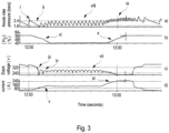
- FIG. 3a, 3b, 3c, and 3d show plots of anode inlet pressure, [H 2 ] at the anode outlet, stack voltage, and current versus time respectively over a time period just before and then after the voltage reversal event.
- the oscillation in anode inlet pressure is noted as being relatively large (denoted "i" in Figure 3a ).
- the anode inlet pressure is seen to go to a minimum (denoted “ii”).
- the stack voltage is seen to dip substantially (denoted “iii") when the anode inlet pressure initially went low and afterwards rises by about 20 volts (denoted “iv”) when the anode pressure rose again.
- the stack current is seen to increase (denoted "v”).
- the [H 2 ] at the anode outlet is seen to drop substantially at this time too (denoted "vi”).
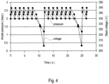
- Figure 4 illustrates an option for increasing the sensitivity of the inventive method by periodically reducing the fuel pressure at the anode inlet.
- the anode inlet pressure and stack voltage versus time of a theoretically similar fuel cell stack are illustrated. Over most of the plot, the anode fuel pressure is assumed to oscillate in the usual manner with the stack voltage oscillating in step accordingly. Periodically though, the anode fuel pressure is considered to be reduced by about a factor of 3 greater than usual. However, the stack voltage is expected to drop by a factor much greater than 3 at these times.
- the amplitude of oscillation in the electrical output i.e. stack voltage
- This procedure would also be expected to help with water management in the fuel cells because the jet pump gives higher changes in anode inlet pressure at lower absolute anode inlet pressures and the change lasts for longer.
Landscapes
- Life Sciences & Earth Sciences (AREA)
- Sustainable Development (AREA)
- Engineering & Computer Science (AREA)
- Manufacturing & Machinery (AREA)
- Sustainable Energy (AREA)
- Chemical & Material Sciences (AREA)
- Chemical Kinetics & Catalysis (AREA)
- Electrochemistry (AREA)
- General Chemical & Material Sciences (AREA)
- Fuel Cell (AREA)
Description
- This invention relates to methods for detecting and lessening fuel starvation conditions in an operating fuel cell system. In particular, it relates to fuel cell systems comprising a solid polymer electrolyte fuel cell with regulating apparatus for regulating the pressure of fuel supplied to the anode inlet, in which the outlet pressure from the regulating apparatus oscillates when the fuel cell system is operating.
- Fuel cells such as solid polymer electrolyte (or proton exchange membrane) fuel cells electrochemically convert fuel and oxidant reactants (such as hydrogen and oxygen or air respectively) to generate electric power. Solid polymer electrolyte fuel cells employ a proton conducting, solid polymer membrane electrolyte between cathode and anode electrodes. A structure comprising a solid polymer membrane electrolyte sandwiched between these two electrodes is known as a membrane electrode assembly (MEA). In a typical fuel cell, flow field plates comprising numerous fluid distribution channels for the reactants are provided on either side of a MEA to distribute fuel and oxidant to the respective electrodes and to remove by-products of the electrochemical reactions taking place within the fuel cell. Water is the primary by-product in a cell operating on hydrogen and air reactants. Because the output voltage of a single cell is of order of 1V, a plurality of cells is usually stacked together in series for commercial applications in order to provide a higher output voltage. Fuel cell stacks can be further connected in arrays of interconnected stacks in series and/or parallel for use in automotive applications and the like.
- Along with water, heat is a significant by-product from the electrochemical reactions taking place within the fuel cell. Means for cooling a fuel cell stack is thus generally required. Stacks designed to achieve high power density (e.g. automotive stacks) typically circulate liquid coolant throughout the stack in order to remove heat quickly and efficiently. To accomplish this, coolant flow fields comprising numerous coolant channels are also typically incorporated in the flow field plates of the cells in the stacks. The coolant flow fields may be formed on the electrochemically inactive surfaces of the flow field plates and thus can distribute coolant evenly throughout the cells while keeping the coolant reliably separated from the reactants.
- A fuel cell system based on a solid polymer electrolyte fuel cell stack or stacks therefore typically contains several subsystems for delivering the reactant and coolant fluids to the fuel cell stack and for exhausting the exhaust fluids from the fuel cell stack. These subsystems can employ apparatus for purposes of controlling the pressure and flow rates of the supplied fluids, for adjusting the humidity and/or temperature of the fluids, and/or for removing water from the exhaust fluids. A fuel supply subsystem usually at least comprises a fuel supply (e.g. hydrogen) and a regulating apparatus for regulating the pressure of fuel supplied to the anode inlet of the fuel cell stack. In addition though, many fuel supply subsystems include a fuel recirculation line for recirculating exhaust from the anode outlet back to the anode inlet. This recirculation prevents stagnation in the stack anodes and allows for water to be removed while minimizing wastage of supplied fuel. To drive the recirculation of the exhaust fluid, the subsystem typically incorporates apparatus such as a jet pump or hydrogen recycle blower. In common embodiments of fuel supply subsystems, the functioning is such that the outlet pressure from the regulating apparatus oscillates during operation of the fuel cell system.
- A potential issue with a series stack of electrochemical cells of any kind is the possibility for having voltage reversals occur in one or more cells in the stack. This can happen when, for some reason, an affected cell becomes incapable of delivering the same amount of current as its peers in the stack. If the cell is weak enough and the current drawn from the stack is high enough, the other cells in the stack can drive the weak cell into a voltage reversal condition. This can cause damage to the weak cell, thereby weakening it even further. The performance capability of the stack is degraded accordingly.
- In fuel cells, fuel starvation is a well known condition that can weaken a cell and lead to voltage reversal situations. Fuel starvation can arise for various reasons. For instance, after storage in below freezing conditions, ice may form in the flow fields of the fuel cells and block the flow of fuel in or to the anode in a cell in the stack. The now inadequate supply of fuel in that cell results in a fuel starvation condition. The affected cell can then be driven into voltage reversal by the current from other cells in the series stack, and can suffer rapid and severe damage depending on the extent and duration of the voltage reversal. Stack failure may occur through internal shorting. Reversals, if undetected and unmitigated, can cause catastrophic stack failure.
- Numerous approaches have been proposed in the art for dealing with the problems associated with voltage reversal, and particularly for preventing or dealing with fuel starvation conditions that can lead to voltage reversal.
US6936370 discusses various circumstances which can result in a solid polymer electrolyte fuel cell being driven into voltage reversal as well as the reactions taking place within. And further,US6936370 discloses means for improving the tolerance of cells against the adverse effects of voltage reversal. For instance, in order to pass current during fuel starvation, reactions such as water electrolysis and oxidation of anode components may take place at the fuel cell anode. The latter reactions can result in irreversible damage. However, promoting the former electrolysis reaction over anode component oxidation can make fuel cells much more tolerant to cell reversal. This can be accomplished by incorporating a catalyst composition at the anode to promote the water electrolysis reaction, in addition to the typical anode catalyst used to promote fuel oxidation. The incorporated catalyst composition is thus selected specifically to electrolyze water and is commonly known as an oxidation evolution reaction catalyst. A typical catalyst composition for this purpose comprises iridium oxide. - Another approach is to detect and then take appropriate action to mitigate against voltage reversals. A common approach in the art has been to implement cell voltage monitoring in the system, which involves monitoring the voltage of each individual cell in the stack. While voltage reversal can reliably be detected in this manner, the cell voltage monitor (CVM) apparatus required can be prohibitively complex and expensive. Such an approach is disclosed in
US 2014/0162160 A1 together with some kind of remedial actions. - Other techniques developed in the field to detect voltage reversal conditions and to prevent any resulting damage include for instance, granted Japanese patents
JP5200414 JP5287815 Japanese patent JP4998609 US20130095405 discloses a fuel cell system and method based on use of an accumulated current value measuring unit. - In another approach, high anode fuel partial pressures may be employed to reduce the likelihood of fuel starvation. However, using high fuel partial pressures generally cause large losses of fuel from permeation. In yet another approach, frequent and thorough purging of the anodes which has been triggered by the measured fuel and nitrogen concentrations has been considered. However, such an approach requires the use of costly fuel and nitrogen sensors.
-
Form EP 2 544 287 A1 a method for determination of deterioration of a fuel cell stack powered with a hydrogen containing gas from a reformer in known. In this document an oscillation of the input pressure as well as an oscillation of the power output is used to determine the deterioration of the fuel cell stack over time. - As further
prior art DE 10 2009 036 197 A1 could be mentioned. It describes an anode loop for a fuel cell system. The purge valve in this anode loop is controlled in relation to a voltage of the stack.US 2013/0344406 A1 discloses an fuel cell system with an anode and a cathode loop. - Despite the advances made to date, there remains a need for better protection of fuel cell systems from harm arising from potential fuel starvation events during operation. This invention represents an option for fulfilling these needs and provides further related advantages.
- Fuel cell systems typically have a regulating apparatus for regulating the pressure of the fuel supplied to the fuel cell stack in the system. In systems where the outlet pressure from the regulating apparatus oscillates during operation (e.g. systems equipped with a fuel recirculation loop and a regulating apparatus comprising a jet pump in the loop), the performance of the fuel cell stack will also oscillate to a certain extent as a result of the periodic increase in fuel pressure provided to the anodes in the fuel cell stack. It was noticed however that the amplitude of these oscillations in stack performance could at times become more significant. It was determined that this can result when the stack is undergoing a fuel starvation event in one or more cells, and the increase in fuel pressure and hydrogen flow through the stack can cause these regions of partial fuel starvation to recover, thereby resulting in a more noticeable increase in fuel cell stack performance. It was realized that partial fuel starvation conditions could thus be detected and lessened by monitoring the electrical output of the fuel cell stack and by taking appropriate remedial action based on the amplitude of the oscillations in this electrical output.
- Specifically, the method of the invention relates to fuel cell systems comprising a solid polymer electrolyte fuel cell, an oxidant supply subsystem, a fuel supply subsystem which at least comprises a fuel supply and a regulating apparatus for regulating the pressure of fuel supplied to an anode inlet of the fuel cell, and an electrical output monitor for monitoring an electrical output of the fuel cell. In the fuel supply subsystem, the fuel supply is connected to an inlet of the regulating apparatus and the anode inlet of the fuel cell is connected to an outlet of the regulating apparatus. Further, the outlet pressure from the regulating apparatus outlet oscillates when the fuel cell system is operating. The inventive method comprises monitoring the electrical output of the fuel cell while the fuel cell system is operating, determining the amplitude of oscillation in the electrical output of the fuel cell resulting from the oscillation in the regulating apparatus outlet pressure, and if the determined amplitude of oscillation in the electrical output exceeds a predetermined amount (thereby indicating a fuel starvation condition), taking a remedial action to lessen the fuel starvation condition.
- In an exemplary embodiment of the invention, the fuel supply subsystem can comprise a fuel recirculation line connecting an anode outlet of the fuel cell to the anode inlet of the fuel cell, and the regulating apparatus comprises a jet pump. The jet pump can comprise a high pressure nozzle inlet, a low pressure inlet, and an outlet. And in the subsystem, the fuel supply is connected to the high pressure nozzle inlet and the fuel recirculation line is connected in series to the low pressure inlet and the outlet of the jet pump.
- In an alternative embodiment, the fuel supply subsystem may also comprise a fuel recirculation line connecting an anode outlet of the fuel cell to the anode inlet of the fuel cell, while the regulating apparatus may comprise a hydrogen recycle blower.
- In a yet further alternative embodiment, the fuel supply subsystem may not employ a fuel recirculation line or loop. Here, the regulating apparatus may instead simply comprise an on-off valve.
- The method is appropriate for use in fuel cell systems in which the outlet pressure from the regulating apparatus outlet oscillates relatively quickly, e.g. with a period of less than 5 seconds. Suitable electrical output monitors for use in the fuel cell system include a voltage output monitor or a current output monitor when the electrical output is voltage or current respectively.
- In embodiments in which operation of the fuel cell system comprises a normal periodic purging step comprising purging a normal amount of purge gas from the fuel cell anode, a suitable remedial action can comprise purging a greater than normal amount of purge gas from the fuel cell anode if the determined amplitude of oscillation in the electrical output exceeds the predetermined amount. In other embodiments, suitable remedial actions include operating the regulating apparatus such that the outlet pressure from the regulating apparatus outlet is at greater pressure, reducing the current drawn from the fuel cell, delaying an increase in the current drawn from the fuel cell, reducing the coolant inlet temperature, and/or increasing the relative humidity of the oxidant supplied to the fuel cell cathode.
- If desired, the sensitivity of the method can be increased by periodically reducing the fuel pressure at the anode inlet of the fuel cell. Such action can increase the amplitude of oscillation in the electrical output of the fuel cell.
- The method of the invention is for use in systems comprising solid polymer electrolyte fuel cell stacks, and is particularly suitable for use in automotive fuel cell systems. For instance, by detecting and addressing fuel starvation situations in this way, there is no need for a complex and expensive CVM apparatus in the system.
- Systems of the invention comprise a solid polymer electrolyte fuel cell, an oxidant supply subsystem, a fuel supply subsystem, and an electrical output monitor for monitoring an electrical output of the fuel cell. The fuel supply subsystem therein comprises a fuel supply, and a regulating apparatus for regulating the pressure of fuel supplied to an anode inlet of the fuel cell in which the fuel supply is connected to an inlet of the regulating apparatus and the anode inlet of the fuel cell is connected to an outlet of the regulating apparatus, and in which the outlet pressure from the regulating apparatus outlet oscillates when the fuel cell system is operating. In addition, the system is configured to operate according to the aforementioned methods.
- These and other aspects of the invention are evident upon reference to the attached Figure and following detailed description.
-
-
Figures 1a, 1b and 1c show simplified schematics of exemplary automotive fuel cell systems in which different options are employed for the regulating apparatus of the fuel supply subsystem. The system inFigure 1a employs a simple on-off valve but no recirculation. The systems inFigures 1b and 1c employ a jet pump and a hydrogen recycle blower respectively, and both recirculate the fuel. -
Figure 2 shows plots of voltage versus anode inlet pressure for a fuel cell stack in the Examples. -
Figures 3a, 3b, 3c, and 3d show plots of anode inlet pressure, [H2] at the anode outlet, stack voltage, and current versus time respectively for a fuel cell stack in the Examples, just before and just after a voltage reversal event. -
Figure 4 illustrates an option for increasing the sensitivity of the inventive method by periodically reducing the fuel pressure at the anode inlet. InFigure 4 , the anode inlet pressure and stack voltage versus time are illustrated. - In this specification, words such as "a" and "comprises" are to be construed in an open-ended sense and are to be considered as meaning at least one but not limited to just one.
- Herein, in a quantitative context, the term "about" should be construed as being in the range up to plus 10% and down to minus 10%.
- The present methods of the invention are useful for detecting and lessening fuel starvation conditions in certain operating fuel cell systems. Applicable fuel cell systems comprise a solid polymer electrolyte fuel cell with a regulating apparatus for regulating the pressure of fuel supplied to the anode inlet of the fuel cell, and in which the outlet pressure from the regulating apparatus oscillates during operation. The methods involve monitoring an electrical output of the fuel cell during operation, determining the amplitude of oscillation in the electrical output, and then, if the determined amplitude of oscillation in the electrical output exceeds a predetermined amount thereby indicating a fuel starvation condition, taking a remedial action to lessen the fuel starvation condition.
-
Figures 1a, 1b and 1c show simplified schematics of exemplary applicable fuel cell systems which may be used in automotive applications. In each figure, a different applicable option is employed for the regulating apparatus of the fuel supply subsystem. The fuel supply subsystem inFigure 1a employs a simple on-off valve but does no recirculation of fuel from the anode outlet back to the anode inlet. The subsystems inFigures 1b and 1c employ a jet pump and a hydrogen recycle blower respectively, and both include a recirculation loop to recirculate the fuel. - In
Figure 1a , the fuel cell system includesfuel cell stack 1 which comprises a series stack of solid polymer electrolyte fuel cells (not called out inFigure 1a ). An oxidant supply subsystem (not called out) is used to deliver compressed ambient air (which has been filtered, cooled and humidified as required) as the supply of oxidant tocathode inlet 2a offuel cell stack 1. Oxygen-depleted air and by-product water vapour and liquid water is exhausted fromfuel cell stack 1 atcathode outlet 2b.Fuel supply subsystem 3 comprises a compressedhydrogen fuel supply 31 and on-offvalve 32 which serves as a regulating apparatus for regulating the pressure of the hydrogen supplied toanode inlet 3a. The outlet pressure from on-offvalve 32 oscillates as it is opened and closed while the fuel cell system is operating. The hydrogen depleted exhaust stream from the anode offuel cell stack 1 is exhausted atanode outlet 3b. To maintain an appropriate operating temperature forfuel cell stack 1, a coolant supply subsystem (not called out) is used to circulate coolant within the stack viacoolant inlet 4a andcoolant outlet 4b. Electrical power is output fromfuel cell stack 1 at positive andnegative terminals Figure 1a , the relevant electrical output being monitored is the stack voltage andvoltmeter 6 serves as the electrical output monitor. - The fuel cell system of
Figure 1b is similar to that ofFigure 1a except that fuel cell subsystem additionally comprises recirculation loop 33 (which connectsanode outlet 3b toanode inlet 3a) andjet pump 34. Here, on-offvalve 32 again serves to provide regulation for the regulating apparatus. Via on-offvalve 32,fuel supply 31 is connected to highpressure nozzle inlet 34a ofjet pump 34. Exhaust fromanode outlet 3b is delivered tolow pressure inlet 34b ofjet pump 34 viarecirculating loop 33. Andanode inlet 3a is connected tooutlet 34c ofjet pump 34. The outlet pressure fromjet pump 34 oscillates as a result of cycling of on-offvalve 32 while the fuel cell system is operating. - The fuel cell system of
Figure 1c is similar to that ofFigure 1b except that instead ofjet pump 34, fuel cell subsystem employshydrogen recycle blower 36 to power the recirculation of fuel inrecirculation loop 33. The outlet pressure fromhydrogen recycle blower 36 oscillates as a result of cycling of the hydrogen recycle blower while the fuel cell system is operating. - In general, the method of the invention involves identifying a fuel starvation condition based on the oscillations that arise in the electrical output of the fuel cell as a result of oscillations occurring in the outlet fuel pressure from the regulating apparatus. To do so, an appropriate electrical output of the fuel cell is monitored while the fuel cell system is operating. From that, the amplitude of oscillation in the electrical output of the fuel cell is determined, and a fuel starvation condition is indicated if the determined amplitude of oscillation in the electrical output exceeds a predetermined amount. An appropriate remedial action is then taken to lessen the fuel starvation condition.
- The monitored electrical output of the fuel cell can be voltage or current. For instance, in an embodiment comprising a jet pump as a regulating apparatus (as shown in
Figure 1b ), the fuel cell stack performance varies during the jet pump cycles. Typically, the outlet pressure of the fuel pump might oscillate with a relatively short period (e.g. < 5 seconds). In an alternative embodiment, the stack voltage rise during initial pressurization of the anode loop may be monitored. Here, voltage oscillations with increasing anode pressure are indicative of possible fuel starvation events. - In setting an appropriate and satisfactory value for the predetermined amount which is used to identify when remedial action is to be taken, consideration is given to voltage changes associated with fuel starvation in individual cells and also the number of cells in the series stack. In individual cells, fuel starvation conditions, or the onset of them, may be associated with voltage changes of about 200 mV up to 1V. In a stack comprising several hundred cells, this amounts to only an average of several mV/cell. Based on the preceding description and representative information appearing in the Examples to follow, those skilled in the art will be expected to be able to determine an appropriate voltage change (i.e. predetermined amount) for a given stack design and operating conditions to effectively detect the onset of potentially problematic fuel starvation conditions. And thereafter, appropriate remedial action can be taken.
- Then, in case that a fuel starvation event is detected, the method comprises taking one or more remedial actions to lessen and preferably clear the fuel starvation condition. These methods include:
- in fuel cell stacks employing a normal periodic purging step during operation, purging more than the usual amount of purge gas from the fuel cell anode;
- avoiding low anode pressure, by operating the regulating apparatus such that the outlet pressure from the regulating apparatus outlet is at greater pressure. If necessary, the cathode pressure could also be increased to avoid exceeding a cross-pressure limit across the cathode and anode;
- reducing the current drawn from the fuel cell, even to zero, especially during start-up below freezing temperatures when the risk of voltage reversals is great;
- delaying an increase in the current drawn from the fuel cell, e.g. delaying driving away normally after starting a fuel cell vehicle;
- reducing the coolant inlet temperature in stacks with circulating liquid coolant; and
- increase the relative humidity of the oxidant supplied to the cathode inlet of the fuel cells to mitigate over-drying of the active area inlet which can occur at low fuel recirculation rates.
- In order to make the inventive method more sensitive, certain additional techniques may optionally be employed. For instance, such techniques include periodically reducing the anode pressure (as demonstrated in the following Examples).
- The following Examples have been provided to illustrate certain aspects of the invention, but they should not be construed as limiting in any way.
- Examples:
In the following tests, a fuel cell system comprising a solid polymer electrolyte fuel cell stack and suitable for use in automotive applications was employed. The system employed a recirculation line for recirculating anode exhaust back to the anode inlet. A jet pump was employed in the recirculation line as generally shown in the schematic ofFigure 1b . - The reactants supplied to the stack were hydrogen and air and the stack was operated under conditions typical of automotive applications. In particular, fresh fuel was supplied to the stack via an on-off type of regulating apparatus. This resulted in cycling of the jet pump output pressure and hence cycling of the anode inlet pressure.
-
Figure 2 illustrates the sensitivity of stack voltage to the pressure of the fuel supplied to the anode inlet of the stack. InFigure 2 , the stack voltage and pressure at the anode inlet were logged at a 1 Hz frequency while the stack was operated with the jet pump cycling. The [H2] at the anode outlet was 25% in this example. The anode inlet pressure was seen to vary over a range from about 0.5 to 1.5 barg. A significant and measurable variation in stack voltage was also observed as a function of the anode inlet pressure. In this test, the stack voltage declined rapidly when the anode pressure inlet fell below 0.5 barg. - A similar fuel cell system to that of
Figure 2 was undergoing routine lifetime testing and was being monitored extensively and continuously while operating. (This included monitoring of both stack and individual fuel cell voltages, stack current, reactant pressures, along with other parameters.) An unexpected voltage reversal event occurred during this testing as a result of insufficient routine anode purging.Figures 3a, 3b, 3c, and 3d show plots of anode inlet pressure, [H2] at the anode outlet, stack voltage, and current versus time respectively over a time period just before and then after the voltage reversal event. At time ~ 12:50 inFigure 3 , the oscillation in anode inlet pressure is noted as being relatively large (denoted "i" inFigure 3a ). Shortly afterwards at time ~ 12:51, the anode inlet pressure is seen to go to a minimum (denoted "ii"). The stack voltage is seen to dip substantially (denoted "iii") when the anode inlet pressure initially went low and afterwards rises by about 20 volts (denoted "iv") when the anode pressure rose again. The stack current is seen to increase (denoted "v"). And the [H2] at the anode outlet is seen to drop substantially at this time too (denoted "vi"). These observations signal the onset of a fuel starvation condition. From individual cell voltage monitoring (not shown inFigure 3 ), it was found that several individual cells went into voltage reversal at this time too (dropping to voltages circa -1.2 V). Following these events, the stack voltage is seen to oscillate (denoted "vii") in step with the oscillations in the anode inlet pressure (denoted "viii"). At time ~ 13:00 inFigure 3 , the anode inlet pressure was increased (denoted "ix") and this resulted in an observable increase in [H2] at the anode outlet (denoted "x"). (The stack current is also seen to increase (denoted "xi"). However, by now it is too late to help prevent severe damage. From individual cell voltage monitoring, it was noted that some individual cells went into deeper reversal (below -2 V) and the current through the stack increased yet again. - It is evident from the details presented in
Figures 3a to 3d that the voltage reversal situation and the severe consequences associated with it could have been prevented by taking appropriate remedial action in response to the noticeable voltage change at time ~ 12:50. -
Figure 4 illustrates an option for increasing the sensitivity of the inventive method by periodically reducing the fuel pressure at the anode inlet. InFigure 4 , the anode inlet pressure and stack voltage versus time of a theoretically similar fuel cell stack are illustrated. Over most of the plot, the anode fuel pressure is assumed to oscillate in the usual manner with the stack voltage oscillating in step accordingly. Periodically though, the anode fuel pressure is considered to be reduced by about a factor of 3 greater than usual. However, the stack voltage is expected to drop by a factor much greater than 3 at these times. As is evident then fromFigure 4 , the amplitude of oscillation in the electrical output (i.e. stack voltage) should increase with the periodic reduction in anode inlet pressure. This procedure would also be expected to help with water management in the fuel cells because the jet pump gives higher changes in anode inlet pressure at lower absolute anode inlet pressures and the change lasts for longer. - While particular elements, embodiments and applications of the present invention have been shown and described, it will be understood, of course, that the invention is not limited thereto since modifications may be made by those skilled in the art without departing from the scope of the present disclosure, particularly in light of the foregoing teachings. Such modifications are to be considered within the scope of the claims appended hereto.
Claims (12)
- A method for detecting and lessening a fuel starvation condition in an operating fuel cell system, the fuel cell system comprising:a solid polymer electrolyte fuel cell,an oxidant supply subsystem,a fuel supply subsystem comprising:a fuel supply, anda regulating apparatus for regulating the pressure of fuel supplied to an anode inlet of the fuel cell wherein the fuel supply is connected to an inlet of the regulating apparatus and the anode inlet of the fuel cell is connected to an outlet of the regulating apparatus, and wherein the outlet pressure from the regulating apparatus outlet oscillates when the fuel cell system is operating, andan electrical output monitor for monitoring an electrical output of the fuel cell,the method comprising:monitoring the electrical output of the fuel cell while the fuel cell system is operating;determining the amplitude of oscillation in the electrical output of the fuel cell resulting from the oscillation in the regulating apparatus outlet pressure; andif the determined amplitude of oscillation in the electrical output exceeds a predetermined amount thereby indicating a fuel starvation condition, taking a remedial action to lessen the fuel starvation condition.
- The method of claim 1 wherein the fuel supply subsystem comprises a fuel recirculation line connecting an anode outlet of the fuel cell to the anode inlet of the fuel cell, and the regulating apparatus comprises a jet pump comprising a high pressure nozzle inlet, a low pressure inlet, and an outlet wherein the fuel supply is connected to the high pressure nozzle inlet and the fuel recirculation line is connected in series to the low pressure inlet and the outlet of the jet pump.
- The method of claim 1 wherein the fuel supply subsystem comprises a fuel recirculation line connecting an anode outlet of the fuel cell to the anode inlet of the fuel cell, and the regulating apparatus comprises a hydrogen recycle blower.
- The method of claim 1 wherein the regulating apparatus comprises an on-off valve.
- The method of claim 1 wherein the outlet pressure from the regulating apparatus outlet oscillates with a period of less than 5 seconds.
- The method of claim 1 wherein the electrical output monitor is a voltage output monitor or a current output monitor.
- The method of claim 6 wherein the electrical output is voltage or current.
- The method of claim 1 wherein operating the fuel cell system comprises a normal periodic purging step comprising purging a normal amount of purge gas from the fuel cell anode, and the remedial action comprises purging a greater than normal amount of purge gas from the fuel cell anode if the determined amplitude of oscillation in the electrical output exceeds the predetermined amount.
- The method of claim 1 wherein the remedial action is selected from the group consisting of operating the regulating apparatus such that the outlet pressure from the regulating apparatus outlet is at greater pressure, reducing the current drawn from the fuel cell, delaying an increase in the current drawn from the fuel cell, reducing the coolant inlet temperature, and increasing the relative humidity of the oxidant supplied to the fuel cell cathode.
- The method of claim 1 comprising periodically reducing the fuel pressure at the anode inlet of the fuel cell, whereby the amplitude of oscillation in the electrical output of the fuel cell is increased.
- The method of claim 1 wherein the fuel cell system is an automotive fuel cell system.
- A fuel cell system comprising:a solid polymer electrolyte fuel cell,an oxidant supply subsystem,a fuel supply subsystem comprising:a fuel supply, anda regulating apparatus for regulating the pressure of fuel supplied to an anode inlet of the fuel cell wherein the fuel supply is connected to an inlet of the regulating apparatus and the anode inlet of the fuel cell is connected to an outlet of the regulating apparatus, and wherein the outlet pressure from the regulating apparatus outlet oscillates when the fuel cell system is operating, andan electrical output monitor for monitoring an electrical output of the fuel cell,wherein the system is configured to operate according to the method of claim 1.
Applications Claiming Priority (2)
| Application Number | Priority Date | Filing Date | Title |
|---|---|---|---|
| US201762460764P | 2017-02-18 | 2017-02-18 | |
| PCT/IB2018/000077 WO2018150251A1 (en) | 2017-02-18 | 2018-02-02 | Method for detecting and lessening fuel starvation in fuel cell systems |
Publications (2)
| Publication Number | Publication Date |
|---|---|
| EP3583647A1 EP3583647A1 (en) | 2019-12-25 |
| EP3583647B1 true EP3583647B1 (en) | 2023-03-22 |
Family
ID=61283262
Family Applications (1)
| Application Number | Title | Priority Date | Filing Date |
|---|---|---|---|
| EP18707407.5A Active EP3583647B1 (en) | 2017-02-18 | 2018-02-02 | Method for detecting and lessening fuel starvation in fuel cell systems |
Country Status (5)
| Country | Link |
|---|---|
| US (1) | US11411235B2 (en) |
| EP (1) | EP3583647B1 (en) |
| JP (1) | JP7293117B2 (en) |
| CN (1) | CN110582879B (en) |
| WO (1) | WO2018150251A1 (en) |
Families Citing this family (3)
| Publication number | Priority date | Publication date | Assignee | Title |
|---|---|---|---|---|
| US10971745B2 (en) * | 2018-01-10 | 2021-04-06 | GM Global Technology Operations LLC | Cell reversal diagnostics for a fuel cell stack |
| JP7208832B2 (en) * | 2019-03-07 | 2023-01-19 | 株式会社豊田自動織機 | FUEL CELL SYSTEM, VEHICLE, AND CONTROL METHOD FOR FUEL CELL SYSTEM |
| DE102024205646A1 (en) * | 2024-06-19 | 2025-12-24 | Robert Bosch Gesellschaft mit beschränkter Haftung | Fuel cell system and method for operating a fuel cell system |
Family Cites Families (14)
| Publication number | Priority date | Publication date | Assignee | Title |
|---|---|---|---|---|
| JPS52414B2 (en) | 1973-10-25 | 1977-01-07 | ||
| US6936370B1 (en) | 1999-08-23 | 2005-08-30 | Ballard Power Systems Inc. | Solid polymer fuel cell with improved voltage reversal tolerance |
| US20080206610A1 (en) * | 2005-09-30 | 2008-08-28 | Saunders James H | Method of Operating an Electrochemical Device Including Mass Flow and Electrical Parameter Controls |
| GB2434437B (en) * | 2006-01-19 | 2011-01-26 | Siemens Ag | Improvements in or relating to combustion apparatus |
| DE102009036197B4 (en) | 2009-08-05 | 2013-03-07 | Daimler Ag | Method for operating a fuel cell system |
| US20120315560A1 (en) * | 2010-03-01 | 2012-12-13 | Aisin Seiki Kabushiki Kaisha | Fuel cell system, fuel cell control method, and fuel cell determination method |
| JP4998609B2 (en) | 2010-05-25 | 2012-08-15 | トヨタ自動車株式会社 | Fuel cell system and control method thereof |
| JP5051273B2 (en) | 2010-05-25 | 2012-10-17 | トヨタ自動車株式会社 | Fuel cell system and control method thereof |
| JP5287815B2 (en) | 2010-09-28 | 2013-09-11 | トヨタ自動車株式会社 | Fuel cell system, negative voltage factor identification method and program |
| FR2971087B1 (en) * | 2011-02-01 | 2013-01-18 | Soc Tech Michelin | RECYCLING LOOP FOR FUEL CELL |
| KR101293979B1 (en) * | 2011-12-21 | 2013-08-07 | 현대자동차주식회사 | Control method for pressure flow oscillation in the anode of fuel cell stack |
| TWI458996B (en) * | 2012-12-07 | 2014-11-01 | Ind Tech Res Inst | Fuel cell failure prediction apparatus and method |
| JP6303941B2 (en) * | 2014-09-12 | 2018-04-04 | 株式会社デンソー | Heat transport system |
| WO2016067789A1 (en) * | 2014-10-28 | 2016-05-06 | 日産自動車株式会社 | Fuel cell system and control method therefor |
-
2018
- 2018-02-02 EP EP18707407.5A patent/EP3583647B1/en active Active
- 2018-02-02 US US16/480,630 patent/US11411235B2/en active Active
- 2018-02-02 JP JP2019544735A patent/JP7293117B2/en active Active
- 2018-02-02 CN CN201880012107.4A patent/CN110582879B/en active Active
- 2018-02-02 WO PCT/IB2018/000077 patent/WO2018150251A1/en not_active Ceased
Also Published As
| Publication number | Publication date |
|---|---|
| JP7293117B2 (en) | 2023-06-19 |
| WO2018150251A1 (en) | 2018-08-23 |
| US11411235B2 (en) | 2022-08-09 |
| CN110582879B (en) | 2023-01-10 |
| EP3583647A1 (en) | 2019-12-25 |
| US20190386323A1 (en) | 2019-12-19 |
| JP2020507905A (en) | 2020-03-12 |
| CN110582879A (en) | 2019-12-17 |
Similar Documents
| Publication | Publication Date | Title |
|---|---|---|
| EP2156496B1 (en) | Fuel cell system | |
| CN115241493A (en) | Fuel cell system and aircraft | |
| US8956775B2 (en) | Fuel cell system and method of detecting abnormality of fuel cell system | |
| KR102219191B1 (en) | Redox flow battery system, monitoring method for redox flow battery and control method for redox flow battery | |
| US10714771B2 (en) | Below freezing start-up method for fuel cell system | |
| JP6996340B2 (en) | Fuel cell system and fuel cell control method | |
| US11183699B2 (en) | Fuel cell system and method of controlling fuel cell system | |
| US20140205924A1 (en) | Selectively reacting to the minimum cell voltage drop rate in a fuel cell system | |
| US20140162159A1 (en) | Method for running a fuel cell system with a failed stack health monitor | |
| EP3583647B1 (en) | Method for detecting and lessening fuel starvation in fuel cell systems | |
| JP2026063327A (en) | Water electrolysis system | |
| EP4421210A1 (en) | Water electrolysis system | |
| CN107346827A (en) | Anode overflow is actively remedied | |
| JP5141937B2 (en) | FUEL CELL SYSTEM AND FUEL CELL STATE DIAGNOSIS METHOD | |
| JP2012004138A (en) | Fuel cell system | |
| JP2009146573A (en) | Fuel cell system | |
| WO2008073119A1 (en) | Maintaining performance of a fuel cell power supply |
Legal Events
| Date | Code | Title | Description |
|---|---|---|---|
| STAA | Information on the status of an ep patent application or granted ep patent |
Free format text: STATUS: UNKNOWN |
|
| STAA | Information on the status of an ep patent application or granted ep patent |
Free format text: STATUS: THE INTERNATIONAL PUBLICATION HAS BEEN MADE |
|
| PUAI | Public reference made under article 153(3) epc to a published international application that has entered the european phase |
Free format text: ORIGINAL CODE: 0009012 |
|
| STAA | Information on the status of an ep patent application or granted ep patent |
Free format text: STATUS: REQUEST FOR EXAMINATION WAS MADE |
|
| 17P | Request for examination filed |
Effective date: 20190819 |
|
| AK | Designated contracting states |
Kind code of ref document: A1 Designated state(s): AL AT BE BG CH CY CZ DE DK EE ES FI FR GB GR HR HU IE IS IT LI LT LU LV MC MK MT NL NO PL PT RO RS SE SI SK SM TR |
|
| AX | Request for extension of the european patent |
Extension state: BA ME |
|
| DAV | Request for validation of the european patent (deleted) | ||
| DAX | Request for extension of the european patent (deleted) | ||
| RAP1 | Party data changed (applicant data changed or rights of an application transferred) |
Owner name: FORD MOTOR COMPANY Owner name: CELLCENTRIC GMBH & CO. KG |
|
| GRAP | Despatch of communication of intention to grant a patent |
Free format text: ORIGINAL CODE: EPIDOSNIGR1 |
|
| STAA | Information on the status of an ep patent application or granted ep patent |
Free format text: STATUS: GRANT OF PATENT IS INTENDED |
|
| INTG | Intention to grant announced |
Effective date: 20220913 |
|
| GRAS | Grant fee paid |
Free format text: ORIGINAL CODE: EPIDOSNIGR3 |
|
| GRAA | (expected) grant |
Free format text: ORIGINAL CODE: 0009210 |
|
| STAA | Information on the status of an ep patent application or granted ep patent |
Free format text: STATUS: THE PATENT HAS BEEN GRANTED |
|
| AK | Designated contracting states |
Kind code of ref document: B1 Designated state(s): AL AT BE BG CH CY CZ DE DK EE ES FI FR GB GR HR HU IE IS IT LI LT LU LV MC MK MT NL NO PL PT RO RS SE SI SK SM TR |
|
| REG | Reference to a national code |
Ref country code: GB Ref legal event code: FG4D |
|
| REG | Reference to a national code |
Ref country code: CH Ref legal event code: EP |
|
| REG | Reference to a national code |
Ref country code: IE Ref legal event code: FG4D |
|
| REG | Reference to a national code |
Ref country code: DE Ref legal event code: R096 Ref document number: 602018047458 Country of ref document: DE |
|
| REG | Reference to a national code |
Ref country code: AT Ref legal event code: REF Ref document number: 1555846 Country of ref document: AT Kind code of ref document: T Effective date: 20230415 |
|
| REG | Reference to a national code |
Ref country code: LT Ref legal event code: MG9D |
|
| P01 | Opt-out of the competence of the unified patent court (upc) registered |
Effective date: 20230621 |
|
| REG | Reference to a national code |
Ref country code: NL Ref legal event code: MP Effective date: 20230322 |
|
| PG25 | Lapsed in a contracting state [announced via postgrant information from national office to epo] |
Ref country code: RS Free format text: LAPSE BECAUSE OF FAILURE TO SUBMIT A TRANSLATION OF THE DESCRIPTION OR TO PAY THE FEE WITHIN THE PRESCRIBED TIME-LIMIT Effective date: 20230322 Ref country code: NO Free format text: LAPSE BECAUSE OF FAILURE TO SUBMIT A TRANSLATION OF THE DESCRIPTION OR TO PAY THE FEE WITHIN THE PRESCRIBED TIME-LIMIT Effective date: 20230622 Ref country code: LV Free format text: LAPSE BECAUSE OF FAILURE TO SUBMIT A TRANSLATION OF THE DESCRIPTION OR TO PAY THE FEE WITHIN THE PRESCRIBED TIME-LIMIT Effective date: 20230322 Ref country code: LT Free format text: LAPSE BECAUSE OF FAILURE TO SUBMIT A TRANSLATION OF THE DESCRIPTION OR TO PAY THE FEE WITHIN THE PRESCRIBED TIME-LIMIT Effective date: 20230322 Ref country code: HR Free format text: LAPSE BECAUSE OF FAILURE TO SUBMIT A TRANSLATION OF THE DESCRIPTION OR TO PAY THE FEE WITHIN THE PRESCRIBED TIME-LIMIT Effective date: 20230322 |
|
| REG | Reference to a national code |
Ref country code: SE Ref legal event code: TRGR |
|
| REG | Reference to a national code |
Ref country code: AT Ref legal event code: MK05 Ref document number: 1555846 Country of ref document: AT Kind code of ref document: T Effective date: 20230322 |
|
| PG25 | Lapsed in a contracting state [announced via postgrant information from national office to epo] |
Ref country code: SE Free format text: LAPSE BECAUSE OF FAILURE TO SUBMIT A TRANSLATION OF THE DESCRIPTION OR TO PAY THE FEE WITHIN THE PRESCRIBED TIME-LIMIT Effective date: 20230322 Ref country code: NL Free format text: LAPSE BECAUSE OF FAILURE TO SUBMIT A TRANSLATION OF THE DESCRIPTION OR TO PAY THE FEE WITHIN THE PRESCRIBED TIME-LIMIT Effective date: 20230322 Ref country code: GR Free format text: LAPSE BECAUSE OF FAILURE TO SUBMIT A TRANSLATION OF THE DESCRIPTION OR TO PAY THE FEE WITHIN THE PRESCRIBED TIME-LIMIT Effective date: 20230623 Ref country code: FI Free format text: LAPSE BECAUSE OF FAILURE TO SUBMIT A TRANSLATION OF THE DESCRIPTION OR TO PAY THE FEE WITHIN THE PRESCRIBED TIME-LIMIT Effective date: 20230322 |
|
| PG25 | Lapsed in a contracting state [announced via postgrant information from national office to epo] |
Ref country code: SM Free format text: LAPSE BECAUSE OF FAILURE TO SUBMIT A TRANSLATION OF THE DESCRIPTION OR TO PAY THE FEE WITHIN THE PRESCRIBED TIME-LIMIT Effective date: 20230322 Ref country code: RO Free format text: LAPSE BECAUSE OF FAILURE TO SUBMIT A TRANSLATION OF THE DESCRIPTION OR TO PAY THE FEE WITHIN THE PRESCRIBED TIME-LIMIT Effective date: 20230322 Ref country code: PT Free format text: LAPSE BECAUSE OF FAILURE TO SUBMIT A TRANSLATION OF THE DESCRIPTION OR TO PAY THE FEE WITHIN THE PRESCRIBED TIME-LIMIT Effective date: 20230724 Ref country code: ES Free format text: LAPSE BECAUSE OF FAILURE TO SUBMIT A TRANSLATION OF THE DESCRIPTION OR TO PAY THE FEE WITHIN THE PRESCRIBED TIME-LIMIT Effective date: 20230322 Ref country code: EE Free format text: LAPSE BECAUSE OF FAILURE TO SUBMIT A TRANSLATION OF THE DESCRIPTION OR TO PAY THE FEE WITHIN THE PRESCRIBED TIME-LIMIT Effective date: 20230322 Ref country code: AT Free format text: LAPSE BECAUSE OF FAILURE TO SUBMIT A TRANSLATION OF THE DESCRIPTION OR TO PAY THE FEE WITHIN THE PRESCRIBED TIME-LIMIT Effective date: 20230322 |
|
| PG25 | Lapsed in a contracting state [announced via postgrant information from national office to epo] |
Ref country code: SK Free format text: LAPSE BECAUSE OF FAILURE TO SUBMIT A TRANSLATION OF THE DESCRIPTION OR TO PAY THE FEE WITHIN THE PRESCRIBED TIME-LIMIT Effective date: 20230322 Ref country code: PL Free format text: LAPSE BECAUSE OF FAILURE TO SUBMIT A TRANSLATION OF THE DESCRIPTION OR TO PAY THE FEE WITHIN THE PRESCRIBED TIME-LIMIT Effective date: 20230322 Ref country code: IS Free format text: LAPSE BECAUSE OF FAILURE TO SUBMIT A TRANSLATION OF THE DESCRIPTION OR TO PAY THE FEE WITHIN THE PRESCRIBED TIME-LIMIT Effective date: 20230722 |
|
| REG | Reference to a national code |
Ref country code: DE Ref legal event code: R097 Ref document number: 602018047458 Country of ref document: DE |
|
| PLBE | No opposition filed within time limit |
Free format text: ORIGINAL CODE: 0009261 |
|
| STAA | Information on the status of an ep patent application or granted ep patent |
Free format text: STATUS: NO OPPOSITION FILED WITHIN TIME LIMIT |
|
| PG25 | Lapsed in a contracting state [announced via postgrant information from national office to epo] |
Ref country code: SI Free format text: LAPSE BECAUSE OF FAILURE TO SUBMIT A TRANSLATION OF THE DESCRIPTION OR TO PAY THE FEE WITHIN THE PRESCRIBED TIME-LIMIT Effective date: 20230322 Ref country code: DK Free format text: LAPSE BECAUSE OF FAILURE TO SUBMIT A TRANSLATION OF THE DESCRIPTION OR TO PAY THE FEE WITHIN THE PRESCRIBED TIME-LIMIT Effective date: 20230322 Ref country code: CZ Free format text: LAPSE BECAUSE OF FAILURE TO SUBMIT A TRANSLATION OF THE DESCRIPTION OR TO PAY THE FEE WITHIN THE PRESCRIBED TIME-LIMIT Effective date: 20230322 |
|
| 26N | No opposition filed |
Effective date: 20240102 |
|
| PG25 | Lapsed in a contracting state [announced via postgrant information from national office to epo] |
Ref country code: IT Free format text: LAPSE BECAUSE OF FAILURE TO SUBMIT A TRANSLATION OF THE DESCRIPTION OR TO PAY THE FEE WITHIN THE PRESCRIBED TIME-LIMIT Effective date: 20230322 |
|
| PG25 | Lapsed in a contracting state [announced via postgrant information from national office to epo] |
Ref country code: MC Free format text: LAPSE BECAUSE OF FAILURE TO SUBMIT A TRANSLATION OF THE DESCRIPTION OR TO PAY THE FEE WITHIN THE PRESCRIBED TIME-LIMIT Effective date: 20230322 |
|
| REG | Reference to a national code |
Ref country code: CH Ref legal event code: PL |
|
| PG25 | Lapsed in a contracting state [announced via postgrant information from national office to epo] |
Ref country code: LU Free format text: LAPSE BECAUSE OF NON-PAYMENT OF DUE FEES Effective date: 20240202 |
|
| PG25 | Lapsed in a contracting state [announced via postgrant information from national office to epo] |
Ref country code: CH Free format text: LAPSE BECAUSE OF NON-PAYMENT OF DUE FEES Effective date: 20240229 |
|
| PG25 | Lapsed in a contracting state [announced via postgrant information from national office to epo] |
Ref country code: LU Free format text: LAPSE BECAUSE OF NON-PAYMENT OF DUE FEES Effective date: 20240202 Ref country code: CH Free format text: LAPSE BECAUSE OF NON-PAYMENT OF DUE FEES Effective date: 20240229 |
|
| PG25 | Lapsed in a contracting state [announced via postgrant information from national office to epo] |
Ref country code: BG Free format text: LAPSE BECAUSE OF FAILURE TO SUBMIT A TRANSLATION OF THE DESCRIPTION OR TO PAY THE FEE WITHIN THE PRESCRIBED TIME-LIMIT Effective date: 20230322 |
|
| PG25 | Lapsed in a contracting state [announced via postgrant information from national office to epo] |
Ref country code: BG Free format text: LAPSE BECAUSE OF FAILURE TO SUBMIT A TRANSLATION OF THE DESCRIPTION OR TO PAY THE FEE WITHIN THE PRESCRIBED TIME-LIMIT Effective date: 20230322 |
|
| REG | Reference to a national code |
Ref country code: BE Ref legal event code: MM Effective date: 20240229 |
|
| PG25 | Lapsed in a contracting state [announced via postgrant information from national office to epo] |
Ref country code: BE Free format text: LAPSE BECAUSE OF NON-PAYMENT OF DUE FEES Effective date: 20240229 |
|
| REG | Reference to a national code |
Ref country code: DE Ref legal event code: R082 Ref document number: 602018047458 Country of ref document: DE Representative=s name: PLATZOEDER PATENTANWALTSGESELLSCHAFT MBH, DE |
|
| PG25 | Lapsed in a contracting state [announced via postgrant information from national office to epo] |
Ref country code: IE Free format text: LAPSE BECAUSE OF NON-PAYMENT OF DUE FEES Effective date: 20240202 |
|
| PG25 | Lapsed in a contracting state [announced via postgrant information from national office to epo] |
Ref country code: IE Free format text: LAPSE BECAUSE OF NON-PAYMENT OF DUE FEES Effective date: 20240202 Ref country code: BE Free format text: LAPSE BECAUSE OF NON-PAYMENT OF DUE FEES Effective date: 20240229 |
|
| PG25 | Lapsed in a contracting state [announced via postgrant information from national office to epo] |
Ref country code: CY Free format text: LAPSE BECAUSE OF FAILURE TO SUBMIT A TRANSLATION OF THE DESCRIPTION OR TO PAY THE FEE WITHIN THE PRESCRIBED TIME-LIMIT; INVALID AB INITIO Effective date: 20180202 |
|
| PG25 | Lapsed in a contracting state [announced via postgrant information from national office to epo] |
Ref country code: HU Free format text: LAPSE BECAUSE OF FAILURE TO SUBMIT A TRANSLATION OF THE DESCRIPTION OR TO PAY THE FEE WITHIN THE PRESCRIBED TIME-LIMIT; INVALID AB INITIO Effective date: 20180202 |
|
| PG25 | Lapsed in a contracting state [announced via postgrant information from national office to epo] |
Ref country code: TR Free format text: LAPSE BECAUSE OF FAILURE TO SUBMIT A TRANSLATION OF THE DESCRIPTION OR TO PAY THE FEE WITHIN THE PRESCRIBED TIME-LIMIT Effective date: 20230322 |
|
| PGFP | Annual fee paid to national office [announced via postgrant information from national office to epo] |
Ref country code: SE Payment date: 20260218 Year of fee payment: 9 |
|
| PGFP | Annual fee paid to national office [announced via postgrant information from national office to epo] |
Ref country code: GB Payment date: 20260218 Year of fee payment: 9 |
|
| PGFP | Annual fee paid to national office [announced via postgrant information from national office to epo] |
Ref country code: DE Payment date: 20260217 Year of fee payment: 9 |
|
| PGFP | Annual fee paid to national office [announced via postgrant information from national office to epo] |
Ref country code: FR Payment date: 20260226 Year of fee payment: 9 |