EP3583321B1 - Methods of pumping heat transfer fluid in thermal energy storage systems - Google Patents
Methods of pumping heat transfer fluid in thermal energy storage systems Download PDFInfo
- Publication number
- EP3583321B1 EP3583321B1 EP18753960.6A EP18753960A EP3583321B1 EP 3583321 B1 EP3583321 B1 EP 3583321B1 EP 18753960 A EP18753960 A EP 18753960A EP 3583321 B1 EP3583321 B1 EP 3583321B1
- Authority
- EP
- European Patent Office
- Prior art keywords
- thermal energy
- energy storage
- pressure vessel
- htf
- tes
- Prior art date
- Legal status (The legal status is an assumption and is not a legal conclusion. Google has not performed a legal analysis and makes no representation as to the accuracy of the status listed.)
- Active
Links
Images





Classifications
-
- F—MECHANICAL ENGINEERING; LIGHTING; HEATING; WEAPONS; BLASTING
- F28—HEAT EXCHANGE IN GENERAL
- F28D—HEAT-EXCHANGE APPARATUS, NOT PROVIDED FOR IN ANOTHER SUBCLASS, IN WHICH THE HEAT-EXCHANGE MEDIA DO NOT COME INTO DIRECT CONTACT
- F28D20/00—Heat storage plants or apparatus in general; Regenerative heat-exchange apparatus not covered by groups F28D17/00 or F28D19/00
- F28D20/02—Heat storage plants or apparatus in general; Regenerative heat-exchange apparatus not covered by groups F28D17/00 or F28D19/00 using latent heat
- F28D20/028—Control arrangements therefor
-
- F—MECHANICAL ENGINEERING; LIGHTING; HEATING; WEAPONS; BLASTING
- F04—POSITIVE - DISPLACEMENT MACHINES FOR LIQUIDS; PUMPS FOR LIQUIDS OR ELASTIC FLUIDS
- F04F—PUMPING OF FLUID BY DIRECT CONTACT OF ANOTHER FLUID OR BY USING INERTIA OF FLUID TO BE PUMPED; SIPHONS
- F04F1/00—Pumps using positively or negatively pressurised fluid medium acting directly on the liquid to be pumped
- F04F1/06—Pumps using positively or negatively pressurised fluid medium acting directly on the liquid to be pumped the fluid medium acting on the surface of the liquid to be pumped
- F04F1/14—Pumps using positively or negatively pressurised fluid medium acting directly on the liquid to be pumped the fluid medium acting on the surface of the liquid to be pumped adapted to pump specific liquids, e.g. corrosive or hot liquids
-
- F—MECHANICAL ENGINEERING; LIGHTING; HEATING; WEAPONS; BLASTING
- F03—MACHINES OR ENGINES FOR LIQUIDS; WIND, SPRING, OR WEIGHT MOTORS; PRODUCING MECHANICAL POWER OR A REACTIVE PROPULSIVE THRUST, NOT OTHERWISE PROVIDED FOR
- F03G—SPRING, WEIGHT, INERTIA OR LIKE MOTORS; MECHANICAL-POWER PRODUCING DEVICES OR MECHANISMS, NOT OTHERWISE PROVIDED FOR OR USING ENERGY SOURCES NOT OTHERWISE PROVIDED FOR
- F03G6/00—Devices for producing mechanical power from solar energy
- F03G6/06—Devices for producing mechanical power from solar energy with solar energy concentrating means
- F03G6/068—Devices for producing mechanical power from solar energy with solar energy concentrating means having other power cycles, e.g. Stirling or transcritical, supercritical cycles; combined with other power sources, e.g. wind, gas or nuclear
-
- F—MECHANICAL ENGINEERING; LIGHTING; HEATING; WEAPONS; BLASTING
- F04—POSITIVE - DISPLACEMENT MACHINES FOR LIQUIDS; PUMPS FOR LIQUIDS OR ELASTIC FLUIDS
- F04F—PUMPING OF FLUID BY DIRECT CONTACT OF ANOTHER FLUID OR BY USING INERTIA OF FLUID TO BE PUMPED; SIPHONS
- F04F1/00—Pumps using positively or negatively pressurised fluid medium acting directly on the liquid to be pumped
- F04F1/06—Pumps using positively or negatively pressurised fluid medium acting directly on the liquid to be pumped the fluid medium acting on the surface of the liquid to be pumped
- F04F1/10—Pumps using positively or negatively pressurised fluid medium acting directly on the liquid to be pumped the fluid medium acting on the surface of the liquid to be pumped of multiple type, e.g. with two or more units in parallel
-
- F—MECHANICAL ENGINEERING; LIGHTING; HEATING; WEAPONS; BLASTING
- F17—STORING OR DISTRIBUTING GASES OR LIQUIDS
- F17D—PIPE-LINE SYSTEMS; PIPE-LINES
- F17D1/00—Pipe-line systems
- F17D1/08—Pipe-line systems for liquids or viscous products
- F17D1/12—Conveying liquids or viscous products by pressure of another fluid
-
- F—MECHANICAL ENGINEERING; LIGHTING; HEATING; WEAPONS; BLASTING
- F24—HEATING; RANGES; VENTILATING
- F24S—SOLAR HEAT COLLECTORS; SOLAR HEAT SYSTEMS
- F24S60/00—Arrangements for storing heat collected by solar heat collectors
- F24S60/10—Arrangements for storing heat collected by solar heat collectors using latent heat
-
- F—MECHANICAL ENGINEERING; LIGHTING; HEATING; WEAPONS; BLASTING
- F28—HEAT EXCHANGE IN GENERAL
- F28D—HEAT-EXCHANGE APPARATUS, NOT PROVIDED FOR IN ANOTHER SUBCLASS, IN WHICH THE HEAT-EXCHANGE MEDIA DO NOT COME INTO DIRECT CONTACT
- F28D20/00—Heat storage plants or apparatus in general; Regenerative heat-exchange apparatus not covered by groups F28D17/00 or F28D19/00
- F28D20/0034—Heat storage plants or apparatus in general; Regenerative heat-exchange apparatus not covered by groups F28D17/00 or F28D19/00 using liquid heat storage material
-
- F—MECHANICAL ENGINEERING; LIGHTING; HEATING; WEAPONS; BLASTING
- F28—HEAT EXCHANGE IN GENERAL
- F28D—HEAT-EXCHANGE APPARATUS, NOT PROVIDED FOR IN ANOTHER SUBCLASS, IN WHICH THE HEAT-EXCHANGE MEDIA DO NOT COME INTO DIRECT CONTACT
- F28D20/00—Heat storage plants or apparatus in general; Regenerative heat-exchange apparatus not covered by groups F28D17/00 or F28D19/00
- F28D20/02—Heat storage plants or apparatus in general; Regenerative heat-exchange apparatus not covered by groups F28D17/00 or F28D19/00 using latent heat
-
- F—MECHANICAL ENGINEERING; LIGHTING; HEATING; WEAPONS; BLASTING
- F03—MACHINES OR ENGINES FOR LIQUIDS; WIND, SPRING, OR WEIGHT MOTORS; PRODUCING MECHANICAL POWER OR A REACTIVE PROPULSIVE THRUST, NOT OTHERWISE PROVIDED FOR
- F03G—SPRING, WEIGHT, INERTIA OR LIKE MOTORS; MECHANICAL-POWER PRODUCING DEVICES OR MECHANISMS, NOT OTHERWISE PROVIDED FOR OR USING ENERGY SOURCES NOT OTHERWISE PROVIDED FOR
- F03G6/00—Devices for producing mechanical power from solar energy
- F03G6/071—Devices for producing mechanical power from solar energy with energy storage devices
-
- F—MECHANICAL ENGINEERING; LIGHTING; HEATING; WEAPONS; BLASTING
- F24—HEATING; RANGES; VENTILATING
- F24S—SOLAR HEAT COLLECTORS; SOLAR HEAT SYSTEMS
- F24S20/00—Solar heat collectors specially adapted for particular uses or environments
- F24S20/20—Solar heat collectors for receiving concentrated solar energy, e.g. receivers for solar power plants
-
- F—MECHANICAL ENGINEERING; LIGHTING; HEATING; WEAPONS; BLASTING
- F24—HEATING; RANGES; VENTILATING
- F24S—SOLAR HEAT COLLECTORS; SOLAR HEAT SYSTEMS
- F24S23/00—Arrangements for concentrating solar-rays for solar heat collectors
- F24S23/70—Arrangements for concentrating solar-rays for solar heat collectors with reflectors
- F24S23/71—Arrangements for concentrating solar-rays for solar heat collectors with reflectors with parabolic reflective surfaces
-
- F—MECHANICAL ENGINEERING; LIGHTING; HEATING; WEAPONS; BLASTING
- F28—HEAT EXCHANGE IN GENERAL
- F28D—HEAT-EXCHANGE APPARATUS, NOT PROVIDED FOR IN ANOTHER SUBCLASS, IN WHICH THE HEAT-EXCHANGE MEDIA DO NOT COME INTO DIRECT CONTACT
- F28D20/00—Heat storage plants or apparatus in general; Regenerative heat-exchange apparatus not covered by groups F28D17/00 or F28D19/00
- F28D2020/0004—Particular heat storage apparatus
- F28D2020/0021—Particular heat storage apparatus the heat storage material being enclosed in loose or stacked elements
-
- F—MECHANICAL ENGINEERING; LIGHTING; HEATING; WEAPONS; BLASTING
- F28—HEAT EXCHANGE IN GENERAL
- F28D—HEAT-EXCHANGE APPARATUS, NOT PROVIDED FOR IN ANOTHER SUBCLASS, IN WHICH THE HEAT-EXCHANGE MEDIA DO NOT COME INTO DIRECT CONTACT
- F28D20/00—Heat storage plants or apparatus in general; Regenerative heat-exchange apparatus not covered by groups F28D17/00 or F28D19/00
- F28D20/0034—Heat storage plants or apparatus in general; Regenerative heat-exchange apparatus not covered by groups F28D17/00 or F28D19/00 using liquid heat storage material
- F28D2020/0047—Heat storage plants or apparatus in general; Regenerative heat-exchange apparatus not covered by groups F28D17/00 or F28D19/00 using liquid heat storage material using molten salts or liquid metals
-
- F—MECHANICAL ENGINEERING; LIGHTING; HEATING; WEAPONS; BLASTING
- F28—HEAT EXCHANGE IN GENERAL
- F28D—HEAT-EXCHANGE APPARATUS, NOT PROVIDED FOR IN ANOTHER SUBCLASS, IN WHICH THE HEAT-EXCHANGE MEDIA DO NOT COME INTO DIRECT CONTACT
- F28D20/00—Heat storage plants or apparatus in general; Regenerative heat-exchange apparatus not covered by groups F28D17/00 or F28D19/00
- F28D2020/006—Heat storage systems not otherwise provided for
-
- F—MECHANICAL ENGINEERING; LIGHTING; HEATING; WEAPONS; BLASTING
- F28—HEAT EXCHANGE IN GENERAL
- F28D—HEAT-EXCHANGE APPARATUS, NOT PROVIDED FOR IN ANOTHER SUBCLASS, IN WHICH THE HEAT-EXCHANGE MEDIA DO NOT COME INTO DIRECT CONTACT
- F28D20/00—Heat storage plants or apparatus in general; Regenerative heat-exchange apparatus not covered by groups F28D17/00 or F28D19/00
- F28D2020/0065—Details, e.g. particular heat storage tanks, auxiliary members within tanks
- F28D2020/0078—Heat exchanger arrangements
-
- F—MECHANICAL ENGINEERING; LIGHTING; HEATING; WEAPONS; BLASTING
- F28—HEAT EXCHANGE IN GENERAL
- F28D—HEAT-EXCHANGE APPARATUS, NOT PROVIDED FOR IN ANOTHER SUBCLASS, IN WHICH THE HEAT-EXCHANGE MEDIA DO NOT COME INTO DIRECT CONTACT
- F28D20/00—Heat storage plants or apparatus in general; Regenerative heat-exchange apparatus not covered by groups F28D17/00 or F28D19/00
- F28D2020/0065—Details, e.g. particular heat storage tanks, auxiliary members within tanks
- F28D2020/0082—Multiple tanks arrangements, e.g. adjacent tanks, tank in tank
-
- F—MECHANICAL ENGINEERING; LIGHTING; HEATING; WEAPONS; BLASTING
- F28—HEAT EXCHANGE IN GENERAL
- F28F—DETAILS OF HEAT-EXCHANGE AND HEAT-TRANSFER APPARATUS, OF GENERAL APPLICATION
- F28F2250/00—Arrangements for modifying the flow of the heat exchange media, e.g. flow guiding means; Particular flow patterns
- F28F2250/08—Fluid driving means, e.g. pumps, fans
-
- Y—GENERAL TAGGING OF NEW TECHNOLOGICAL DEVELOPMENTS; GENERAL TAGGING OF CROSS-SECTIONAL TECHNOLOGIES SPANNING OVER SEVERAL SECTIONS OF THE IPC; TECHNICAL SUBJECTS COVERED BY FORMER USPC CROSS-REFERENCE ART COLLECTIONS [XRACs] AND DIGESTS
- Y02—TECHNOLOGIES OR APPLICATIONS FOR MITIGATION OR ADAPTATION AGAINST CLIMATE CHANGE
- Y02E—REDUCTION OF GREENHOUSE GAS [GHG] EMISSIONS, RELATED TO ENERGY GENERATION, TRANSMISSION OR DISTRIBUTION
- Y02E10/00—Energy generation through renewable energy sources
- Y02E10/40—Solar thermal energy, e.g. solar towers
- Y02E10/46—Conversion of thermal power into mechanical power, e.g. Rankine, Stirling or solar thermal engines
-
- Y—GENERAL TAGGING OF NEW TECHNOLOGICAL DEVELOPMENTS; GENERAL TAGGING OF CROSS-SECTIONAL TECHNOLOGIES SPANNING OVER SEVERAL SECTIONS OF THE IPC; TECHNICAL SUBJECTS COVERED BY FORMER USPC CROSS-REFERENCE ART COLLECTIONS [XRACs] AND DIGESTS
- Y02—TECHNOLOGIES OR APPLICATIONS FOR MITIGATION OR ADAPTATION AGAINST CLIMATE CHANGE
- Y02E—REDUCTION OF GREENHOUSE GAS [GHG] EMISSIONS, RELATED TO ENERGY GENERATION, TRANSMISSION OR DISTRIBUTION
- Y02E60/00—Enabling technologies; Technologies with a potential or indirect contribution to GHG emissions mitigation
- Y02E60/14—Thermal energy storage
Definitions
- the present invention pertains to the field of methods and systems for pumping heat transfer fluid in thermal energy storage systems and more particularly to methods of indirect pumping in thermal energy systems comprising a first and second thermal energy storage tank connected by a bi-directional flow member.
- CSP concentrated solar power
- the solar radiation receiver absorbs solar radiation as thermal energy and a conversion system (generally a heat engine) then converts this thermal energy to electrical energy for subsequent distribution.
- a parabolic trough system comprises a large surface area of parabolic trough shaped solar collectors directing solar radiation to a heat transfer fluid (HTF) arranged along a focal axis of the parabolic trough. The HTF is then pumped and used to conduct thermal energy to the conversion system for electrical energy generation.
- HTF heat transfer fluid
- Another system is a power tower whereby solar radiation is directed by fields of mirrors which track the sun toward a static central tower.
- the central tower comprises a HTF which can be used to conduct thermal energy to a conversion system.
- a Linear Fresnel reflector uses a system of flat linear mirrors approximating the parabolic shape of a parabolic trough and directing the solar radiation to a solar receiver comprising a HTF which can be used for subsequent electrical energy generation as described.
- the parabolic dish system comprises a parabolic dish comprising mirror(s) on an inner surface which tracks the sun in 2-axis during the day.
- the solar radiation is concentrated at a focal point by the mirror(s) where it is traditionally converted directly to electrical energy via a conversion system such as a Stirling or Rankine cycle engine.
- a conversion system such as a Stirling or Rankine cycle engine.
- parabolic dish systems can be modular, installed on uneven ground, take less space than the other named system and are especially efficient they are particular ideal candidates for cost-effective CSP systems.
- parabolic dish systems which have a moving solar receiver, do not use a HTF and have no capacity for thermal energy storage as the energy conversion system is located directly at the focal point of the parabolic dish. Without thermal energy storage, the parabolic dish systems only generate electrical energy during hours of sunlight.
- Thermal energy storage systems for storing thermal energy generated during periods of sunlight are known in concentrated solar power systems having static solar receivers but there is a lack of thermal energy storage systems suitable for use with parabolic dish systems.
- the known thermal energy storage systems generally operate with a hot storage tank, operating at up to around 390 °C ⁇ 560 °C, storing thermal energy from the solar receiver (either storing the HTF, or storing energy from the HTF in a different medium).
- the energy in the hot storage tank is thereafter accessed and distributed to the electrical energy generator via the HTF.
- the HTF has a reduced temperature and it, or energy therefrom, is thereafter stored in a cold storage tank operating at around 290 °C or less.
- the cold storage tank acts as a receptacle for the used/cooler fluid. After storage in the cold tank, and when the receiver is again receiving sunlight, the HTF is pumped back to the receiver to be warmed again.
- the fluid must be maintained at a high temperature throughout this entire process and the temperature of the cold tank is always at or below the temperature of the used HTF, and the used HTF cannot be used for the generation of electrical energy until the receiver is receiving sunlight again.
- the present invention preferably seeks to mitigate, alleviate or eliminate one or more of the above-identified deficiencies in the art and disadvantages singly or in any combination and solves at least the above mentioned problems by providing a method of pumping a heat transfer fluid in a thermal energy storage system comprising a first thermal energy storage tank connected to a second thermal energy storage tank via a bi-directional flow member.
- the first and second thermal energy storage tanks are associated with a pressure vessel system comprising a first and second pressure vessel each pressure vessel being partially fillable with an actuating liquid, wherein, the method for pumping comprises: displacing the actuating liquid from the first pressure vessel to the second pressure vessel, thereby creating a pressure difference in the first thermal energy storage tank with respect to the second thermal energy storage tank, and therein displacing the heat transfer fluid via the bi-directional flow member.
- Thermal energy storage systems are also provided.
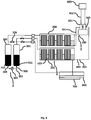
- Fig. 1 shows a thermal energy storage system 2 comprising a first thermal energy storage (TES) tank 200 and a second thermal energy storage (TES) tank 201 for receiving a Heat Transfer Fluid.
- the first and second TES tanks 200, 201 are fluidically connected via at least one bi-directional flow member 202 such that a Heat Transfer Fluid (HTF) can be reversibly displaced from the first TES tank 200 to the second TES tank 201.
- HTF Heat Transfer Fluid
- the bi-directional flow member 202 has a first end provided at a lower region of the first TES tank 200.
- the bi-directional flow member 202 has a second end provided at a lower region of the second TES tank 201.
- the first and second ends of the bi-directional flow member 202 must be positioned such that, during pumping of the HTF, the first and second ends are always immersed in HTF. Otherwise gas bubbles may form in the system. During system initialisation the first and second ends do not need to be immersed in HTF.
- the HTF is displaced by the provision of a pressure differential in the first TES tank 200 with respect to the second TES tank 201.
- the pressure differential generates a force acting on the HTF in the first TES tank 200 and therein actuates the displacement of the HTF to the second tank 201.
- the pressure present at the first end of the bi-directional flow member 202 is greater than the pressure at the second end of the bi-directional flow member 202. This pressure difference means that the HTF flows through the bi-directional flow member 202.
- an ideal way of creating the pressure differential between the first TES tank 200 and the second TES tank 201 is to associate the TES system 2 with at least one pressure vessel system 3.
- a pressure vessel system 3 comprising a first and second pressure vessel 300, 301 is associated with the TES system 2.
- the first pressure vessel 300 is connected to the first TES tank 200.
- the first pressure vessel 300 is connected to the first TES tank 200 by a fluidic conduit having a first end at an upper region of the first pressure vessel 300 and a second end at an upper region of the first TES tank 200.
- the second pressure vessel 301 is connected to the second TES tank 201.
- Each of the first and second pressure vessels 300, 301 is partially filled with an actuating liquid.
- the second pressure vessel 301 is connected to the second TES tank 201 by a fluidic conduit having a first end at an upper region of the second pressure vessel 301 and a second end at an upper region of the second TES tank 200.
- An actuating liquid flow path 303 is provided between the first and second pressure vessels 300, 301.
- the actuating liquid flow path 303 may be connected at a first end 304 to a lower region 310 of the first pressure vessel 300.
- the actuating liquid flow path 303 may also be connected at a second end 306 to a lower region 311 of the second pressure vessel 301.
- a pump 302 is provided in communication with the actuating liquid flow path 303. The pump is for pumping actuating liquid, it does not need to be capable of pumping HTF.
- the total volume of actuating liquid in both the first and second pressure vessels 300, 301 is constant. That is, the volume of actuating liquid in the pressure vessel system 3 is constant.
- the remaining volume of the pressure vessel system 3, that is, the volume not filled with actuating liquid may comprise, such as be filled with a fluid, for example an inert gas such as N2.
- the remaining volume may comprise, such as be filled with CO 2 , especially if the HTF or PCM (see below for further information regarding PCM) comprise carbonate salts.
- Other inert gases such as Argon may also be suitable but cost of such a gas may be prohibitive.
- the pressure vessel system 3 and the TES system 2 are closed and the total volume of the pressure vessel system 3 and the connected TES system 2 is constant. More specifically, the volume of the first and second pressure vessels 300, 301, and the first and second TES tanks 200, 201 is fixed. This enables in-direct pumping of HTF from the first TES tank 200 to the second TES tank 201 and back again without the requirement of a pump acting directly on the HTF.
- the pump 302 acts only on the actuating liquid, and the pressure differential created in the system causes the displacement of HTF. This will now be further described.
- the actuating liquid can be pumped from the first pressure vessel 300 to the second pressure vessel 301 via the pump 302.
- the displacement of the actuating liquid causes a pressure differential in the first TES tank 200 with respect to the second TES tank 201.
- This pressure differential creates a force on any HTF present in the first or second TES tanks 200, 201 and displaces the HTF via the bi-directional flow member 202.
- the first TES tank 200 may be provided at a height above the second TES tank 201.
- the first TES tank 200 and the second 201 need not be thermally isolated from one another. It may be advantageous to have them adjacent and in thermal contact such that any heat energy provided to the first or second TES tank 300, 301 is conducted to the second or first TES tank 301, 300.
- a thermal energy storage system 2 comprising a single pressure vessel is also envisaged.
- the HTF is displaced via the actuation of a mechanical piston acting in the single pressure vessel which displaces an inert gas.
- the displacement of the inert gas causes an increase in pressure at the first TES tank 200 and therein forces the displacement of HTF from the first TES tank 200 to the second TES 201.
- the mechanical piston may then be retracted, causing a reduction in pressure in the first TES tank 200 and therein the HTF is flowed in a reverse direction.
- Another, less preferred, method of displacing the HTF is to displace the first and second TES tanks (200, 201) relative to one another. For example, by raising the first TES tank 200 above the height of the second TES tank 201 the force of gravity acting on the fluid in the first TES tank 200 causes it to flow through the bi-directional flow member 202 in to the second TES tank 201. The second TES tank 201 can thereafter be raised above the first TES tank 200 and the flow is reversed.
- the pressure of HTF at the first end of the bi-directional flow member 202 is increased relative to the pressure at the second end of the bi-directional flow member 202, and therein HTF from the first thermal energy storage tank 200 is displaced to the second thermal energy storage tank 201.
- a valve 305 may be provided between the first and second pressure vessels 300, 301 for equalizing the pressure in the first and second pressure vessels 300, 301.
- the pressure differential between the first and second pressure vessels 300, 301 can be equalized on opening the valve 305.
- the valve 305 is generally closed during system operation such that the pressure vessel system 3 is closed and therein that the pumping of the fluids between the first and second pressure vessel 300, 301 causes a pressure differential between the first and second TES tanks 200, 201.
- a method of pumping heat transfer fluid in a thermal energy storage system wherein the thermal energy storage system may comprise a first thermal energy storage tank connected to a second thermal energy storage tank via a bi-directional flow member.
- the first and second thermal energy storage tanks being connected via fluidic conduits with a pressure vessel system comprising a first and a second pressure vessel each first and second pressure vessel being partially fillable with an actuating liquid, wherein, the pumping is conducted through displacing the actuating liquid from the first pressure vessel to the second pressure vessel, thereby creating a pressure difference in the first thermal energy storage tank with respect to the second thermal energy storage tank, and therein displacing the heat transfer fluid via the bi-directional flow member.
- the thermal energy storage system 2 may be connected to a solar receiver 400.
- the solar receiver 400 receives solar radiation and is generally heated, or a portion thereof is heated.
- solar radiation may be reflected and focused on the solar receiver 400 by a parabolic dish 600 as shown in Figure 2 .
- the parabolic dish 600 comprises a plurality of mirrors 601 reflecting and focusing the solar radiation at a focal point 602.
- the solar receiver 400 is located at a focal point where sunlight is reflected and focused. Referring again, specifically to parabolic dish systems, as the solar parabolic dish 600 moves in 2-axis and tracks the sunlight during the day, the focal point 602 and therein the solar receiver 400 also moves during the day.
- the solar receiver 400 in a parabolic dish 600 CSP system is not static. It is also generally located at a height above ground level.
- Other systems for reflecting and/or focusing solar radiation on the solar receiver 400 may be possible to combine with the thermal energy storage system 2 described herein.
- static solar receiver systems such as parabolic trough, linear Fresnel, and power tower systems could also be used. In such systems, the solar receiver does not move, it is static.
- the solar receiver 400 is thermally connected to the thermal energy storage system 2. As is shown in Figure 1 , the solar receiver may be connected to the first TES tank 200 and connected to the second TES tank 201. Heat generated at the solar receiver 400 is conducted to the first and second TES tanks 200, 201.
- the solar receiver 400 is connected to the first TES tank 200 via a first thermal flow path 401.
- the first thermal flow path 401 may be a conduit for HTF.
- the solar receiver 400 is connected to the second TES via a second thermal flow path 402.
- the second thermal flow path 402 may be a conduit for HTF.
- the first and second thermal flow paths 401, 402 may be connected such that a combined thermal flow path is formed from the first TES tank 200 to the second TES tank 201.
- HTF can flow from the first TES tank 200, through the first thermal flow path 401 to the solar receiver 400, where it may be warmed by solar radiation directed at the solar receiver 400, through the second thermal flow path 402 to the second TES tank 201.
- the HTF is then stored in the second TES tank 201.
- the combined thermal flow path is the bi-directional flow member 202 described above.
- the solar receiver 400 may be provided along the bi-directional flow member 202. HTF may flow through the solar receiver 400.
- the displacement of the HTF from the first/second TES tank to the second/first TES tank 200, 201 can be actuated via indirect pumping whereby a volume of actuation liquid is displaced from the first or second pressure vessel 300, 301 to the second or first pressure vessel 301, 300 thereby creating a pressure difference between the first and second TES tanks 200, 201 and that pressure difference forces the HTF through the first and second thermal flow paths 401, 402.
- the first and second flow paths 401, 402 may be flexible pipes forming conduits for the HTF. The provision of flexible pipes as the first and second flow paths 401, 402 reduces the complexity in systems comprising a parabolic solar dish as the solar receiver inherently 400 moves with the dish and therefore rigid pipes require more complex joints and connections.
- an electrical energy generation system 5 is provided to generate electrical energy from the thermal energy generated by the solar receiver 400, and/or stored in the thermal energy storage system 2.
- the electrical energy generation system 5 is an energy conversion system, converting thermal energy to electrical energy.
- the electricity generated by the electrical energy generation system 5 can be fed in to an electricity grid, or electricity distribution network.
- the electrical energy generation system 5 may comprise a conversion unit 500 operating on the Stirling cycle, Rankine cycle, Brayton cycle, or any other heat engine capable of efficiently generating electrical energy from thermal energy to electrical energy.
- a Stirling engine is shown as the electrical energy generation system 5.
- the conversion unit 500 is in thermal connection with the HTF.
- the conversion unit 500 is in thermal connection with the first and second thermal flow paths 401, 402. Due to the use of a HTF and as opposed to traditional concentrated solar power systems comprising parabolic dishes, the conversion unit 500 need not be located at the focal point 602 of the parabolic dish 600.
- the conversion unit 500 may be provided adjacent to the TES system 2. Providing the Stirling engine at a location not at the focal point 602 of the parabolic dish 600 greatly improves ease of installation and maintenance as the Stirling engine does not need to move with the parabolic dish 600.
- the solar receiver 400 but not the conversion unit 500 moves with the parabolic dish 600.
- the electrical energy generation system 5 may comprise at least one heat exchanger 501 for transferring the thermal energy from the HTF to the working fluid of the conversion unit 500.
- a pair of heat exchangers 501, 502 are shown for receiving energy from the HTF.
- a first heat exchanger 501 is arranged on the first thermal flow path 401
- a second heat exchanger 502 is arranged on the second thermal flow path 402.
- the single thermal flow path is also a flow path for HTF. That is, the flow path forms a conduit for the flow of HTF.
- the electrical energy generation system 5 need not be in fluidic connection to the TES system 2.
- a thermosiphon may be provided between the TES system 2 and the electrical energy generation system 5.
- the thermosiphon is a longitudinally, and generally vertically, extending receptacle comprising a fluid whereby heat energy provided at the lower portion raises under convection and can be extracted at an upper portion.
- the thermosiphon may thermally connect both the first and second TES tanks 200, 201 to the electrical energy generation system 5, such as to the heat exchangers 501, 502.
- the first TES tank 200 and the second TES tank 201 are provided with at least one phase change material PCM for storing and/or releasing energy from/to the HTF.
- the at least one PCM may for example be a salt having a melting point substantially greater than the melting point of the HTF.
- the at least one PCM material may be encapsulated in members physically, but not thermally, isolating the PCM from the HTF.
- the PCM is, as is known in the art, a material which absorbs energy during heating as phase change from e.g. a solid to a liquid takes and releases energy to the adjacent environment during the reversed cooling process.
- a solid to a liquid takes and releases energy to the adjacent environment during the reversed cooling process.
- the solid increases temperature (sensible energy storage).
- phase change from solid to liquid energy is stored latently. After phase change to a liquid energy is again stored sensibly and the PCM in liquid phase increases temperature.
- the PCM in the TES tanks 200, 201 acts as a reliable and predictable thermal energy storage medium. Therein a substantial amount of thermal energy can be stored in the TES system 2 beyond that which could be stored in only the HTF.
- the PCM may comprise any media capable of storing thermal energy such as a salt, or mixture of salts, a particle such as sand, concrete or combinations of the above.
- the PCM may have a melting point from 500 °C to 900 °C, such as from 650 °C to 810 °C.
- the temperature of the first and second TES tanks (200, 201) is from about 500 °C to about 900 °C.
- the HTF has a melting point of from 200 °C to 500 °C, such as from 300 °C to 400 °C.
- the HTF may comprise a molten salt, molten glass and/or liquid metal(s).
- suitable molten salts may be eutectic salts of carbonates, fluorides, or chlorides and/or nitrate salts.
- the HTF may comprise oxides.
- the HTF may also comprise mixtures of the above in various fractions. Whilst named a fluid it is obvious that the HTF is simply a substance which is a fluid, i.e., is at a temperature greater than melting point, at its normal operating temperatures.
- the PCM is comprised within a plurality of members being PCM receptacles 220.
- Each PCM receptacle 220 comprises a portion for storing PCM and a wall which physical separates the PCM in the portion for the storing the PCM from the HTF.
- the PCM receptacles 220 may be longitudinally extending members having a substantially vertical alignment.
- the PCM receptacles 220 may be cylindrical members, having a circular cross-section. They may also be longitudinally extending members have square, hexagonal, or oval cross-sections.
- the PCM receptacles 220 may have an opening in an upper portion such that the PCM can expand freely on phase change without a pressure build-up occurring within the receptacle.
- the PCM receptacles 220 are sealed at the bottom portion such that HTF present in the first and second TES tanks 200, 201 cannot directly contact the PCM.
- the PCM receptacles 220 may be arranged in a grid as shown in Figures 1 , 3 and 5 .
- the PCM receptacles 220 are arranged substantially parallel to each other.
- Figure 5 shows a cut-away view of the thermal energy storage system 2 showing an arrangement of PCM receptacles 220 in both the first and second TES tanks 200, 201.
- the plurality of PCM receptacles 220 are arranged parallel and adjacent to one another in a grid.
- the HTF can flow around the PCM receptacles 220 and therein heat the PCM in the PCM receptacles 220.
- the first and second TES tanks 200, 201 may be provided with a second PCM having a melting point substantially higher than the melting point of the HTF but substantially lower than the melting point of the first PCM.
- This second PCM may be considered a low-temp PCM, with the first PCM being considered a high-temp PCM.
- the low-temp PCM may have a melting point from 0 to 100 °C higher than the melting point of the HTF.
- the TES system 2 may comprise from 0 to 30% by mass of the low-temp PCM.
- One advantage of the low-temp PCM is that the HTF can be maintained in liquid state for longer compared to a TES system 2 not comprising a low-temp PCM.
- the low-temp PCM is not used for maintain the HTF at a temperature suitable for energy generation in the energy conversion system 5 but rather maintains the HTF in a liquid state.
- the TES system 2 may comprise a pre-heater 700 for heating the HTF and TES system 2.
- the pre-heater 700 may be in thermal connection with the first or second TES tank 200,201 and is arranged for heating the HTF on system initialization.
- the pre-heater 700 may be arranged in communication with a separate HTF storage/drainage tank 800.
- the separate HTF storage/drainage tank 800 is provided in fluidic communication with the pressure vessel system 3, for the provision of pressure to displace the HTF, and the first or second TES tank 200, 201, for the transfer of HTF.
- the valve 305 With the TES system 2 off and prior to starting the valve 305 can be opened 1001 and the volume of actuating liquid in each of the first and second pressure vessels 300, 301 is equalized 1002 by the pump 302. As the valve 305 is open the HTF in the TES system 2 will flow, due to the gravity, to the lowest point in the TES system 2. In Figure 1 , the lowest point is the second TES tank 201. By altering the arrangement of the tanks the first TES tank 200 could be positioned lower than the second TES tank 201.Irrespective of which tank is at a higher or lower point, all HTF will be present in a single tank.
- the pre-heater may then begin to pre-heat 1003 the HTF in the second TES tank to or above its melting point.
- Super heating the HTF above its melting point prevents the HTF from freezing if there are cold spots in the system that haven't been pre-heated sufficiently.
- the super heating could be from 1 to 100 °C above the melting point of the HTF, such as from 10 to 50 °C.
- the first and second TES tanks 200, 201 may be thermally connected to each other, and in such a way, heating the second TES tank 201 may, via conduction, heat the first TES tank 200.
- the solar receiver 400 and thermal flow paths 401, 402 are also pre-heated 1004.
- the valve 305 may be closed 1005 such that the first and second pressure vessels 300, 301 are only connected via the actuating liquid flow path 303.
- the actuating liquid is pumped 1006 via the pump 302 to the pressure vessel in connection with the TES tank comprising the HTF.
- the actuating liquid is pumped via the pump 302 to the second pressure vessel 301, which is connected to the second TES tank 201.
- An inert gas, such as N 2 is then provided 1007 to the first TES tank 200. The inert gas acts to charge the system and to aid in pre-heating.
- the inert gas flows through the bi-direction flow member 202 in to the HTF in the second TES tank 201.
- the inert gas may be provided to the first TES tank 200 such that a predetermined pressure in the pressure vessel system 3 is reached.
- the actuating liquid may then be pumped 1008, via the pump 302 from the second pressure vessel 301 to the first pressure vessel 300 such that the inert gas is displaced and flows through the bi-directional flow member 202 and eventually to the second TES tank 201.
- the pressure vessel system 3 is reset.
- the valve 305 is then opened and the actuating liquid is pumped 1009, via the pump 302, to the first pressure vessel 300.
- the actuating liquid is pumped to a height such that pressure provided by the actuating liquid when the pump 302 ceases pumping is sufficient to overcome the static pressure of the HTF at the highest point, above the lowest system level, in the bi-directional flow member 202.
- the highest point in the bi-directional flow member is generally the solar receiver 400.
- the valve 305 can now be closed 1010 and the pressure vessel system 3, and TES system 2 now have a fixed total volume.
- the HTF flows from the second TES tank 201 to the first TES tank 200.
- the volumes of actuating liquid in each of the first and second pressure vessels 300, 301 are equalized such that the volume of HTF in each of the first and second TES is therein equalized.
- the pump 302 to displace the HTF the pump 302 no longer needs to overcome the static pressure of the system. It has to only overcome the internal pressure losses in the HTF conduits.
- the indirect pumping method can then be used to oscillate the HTF from the first TES tank 201 to the second TES tank, via the solar receiver 400.
- a 2 hot-tank TES system 2 with indirect pumping is achieved.
- the system has a great thermal storage capacity as two tanks are utilized for thermal energy storage.
- the pump 302 does not need to pump HTF, but only the actuating liquid, operational costs are significantly reduced.
- Charging the TES system 2 is when the thermal energy stored in the TES system 2 is increased such that it can be accessed later for electrical energy generation. Charging the TES system 2 occurs during hours of sunlight when the solar receiver 400 is receiving sunlight.
- the HTF is oscillated from the first TES tank 200 to the second TES tank 201 via the bi-directional flow member 202.
- the solar receiver 400 is provided at a point along the bi-directional flow member 202.
- the HTF is heated via the solar radiation at the solar receiver 400.
- the HTF may pass through the solar receiver 400.
- the temperature of the HTF on entering the solar receiver 400 is lower than the temperature of the HTF leaving the solar receiver.
- the thermal energy in the HTF is transferred to the PCM, or PCMs, in the first and second TES tanks 200, 201.
- the thermal energy is therein stored in the first and second TES tanks 200, 201.
- Discharging the TES system 2 is when energy stored in the TES system 2 is accessed and therein that the thermal energy present in the system is decreased. Discharging the TES system normally occurs when electrical energy is to be generated by the energy conversion system 5.
- One way of discharging the system is to provide an energy conversion system 5 in thermal connection with the bi-directional flow member 202. HTF is oscillated from the first TES tank 200 to the second TES tank 201 via the bidirectional flow member 202.
- the energy conversion system 5 generally comprises a first heat exchanger 501, provided between on the first thermal flow path 401 of the bi-directional flow member 202, arranged to receive thermal energy from the HTF. The thermal energy is used to drive the energy conversion unit 500 and can thereafter be converted to electrical energy.
- a second heat exchanger 502 can be provided on the second thermal flow path 402 and arranged to receive thermal energy from the HTF.
- the second heat exchanger 502 provides the capacity for improved energy conversion.
- the HTF is oscillated from the first TES tank 200 to the second TES tank 201 and back again.
- During discharging the temperature of the PCM drops as energy is removed from the TES system 2. Once the temperature of the PCM is below its melting point the TES system 2 is considered empty and discharging for electrical energy generation ceases. If, as described previously, the TES system 2 comprises a second low-temp PCM, having a melting point substantially lower than the melting point of the first PCM, then the system is considered empty when the first high-temp PCM has dropped below its melting point.
- the HTF can be maintained in both the first and second TES tanks 200, 201 such that HTF is maintained above its melting point by the thermal energy stored in the PCM. If the TES system comprises a second low-temp PCM then the HTF is maintained above its melting point predominantly by energy stored in the low-temp PCM.
- the PCM in each of the first and second TES tanks 200, 201 are maintained at a temperature higher than the melting point of the HTF.
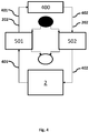
- FIG. 4 shows a schematic of the system.
- the system comprises a TES system 2, a solar receiver 400 and an electrical energy generation system 5.
- a first heat exchanger 501 is provided on the first thermal flow path 401.
- a second heat exchanger 502 is provided on the second thermal flow path 402.
- the thermal flow paths 401, 402 form the bi-directional flow member 202.
- the different temperatures at different points of the system will now be described. As an example, after initialization and during charging the temperature of the TES system 2 may be about 714 °C.
- the temperature of HTF flowing in the first thermal energy flow path 401 between the TES system 2 and the first heat exchanger 501 may therefore in the ideal case be about 714 °C.
- the temperature of the HTF in the first thermal energy flow path 401 after leaving the first heat exchanger 501 and before reaching the solar receiver 400 may be about 704 °C (10 °C drop during heat exchanging).
- the HTF is then heated in the solar receiver 400 by about 40 °C.
- the temperature of the HTF in the second thermal flow path 402, between the solar receiver 400 and the second heat exchanger 502 may therefore be about 744 °C.
- the temperature of HTF in the second thermal flow path 402 after leaving the second heat exchanger 502 may be about 734 °C (10 °C drop during heat exchanging).
- the HTF may slightly increase the temperature of the TES system 2.
- the temperature of the TES system 2 may be about 714 °C.
- the temperature of HTF flowing in the first thermal energy flow path 401 between the TES system 2 and the first heat exchanger 501 may therefore be about 714 °C.
- the temperature of the HTF in the first thermal energy flow path 401 after leaving the first heat exchanger 501 and before reaching the solar receiver 400 may be about 704 °C (10 °C drop during heat exchanging).
- the temperature of the HTF in the second thermal flow path 402, between the solar receiver 400 and the second heat exchanger 502 may therefore be about 704 °C.
- the temperature of HTF in the second thermal flow path 402 after leaving the second heat exchanger 502 may be about 694 °C (10 °C drop during heat exchanging). As the temperature of the TES system 2 was about 714 °C, and the temperature of HTF entering the TES system 2 is about 694 °C then the HTF may slightly decrease the temperature of the TES system 2.
- the HTF flowing from the TES system 2 flows from the first TES tank 200 to the second TES tank 201. As has been described previously it may also flow in a reciprocal or oscillating manner, from the second TES tank 201 to the first TES tank 200.
- This oscillating flow of HTF is used in both charging and discharging the TES system 2.
- the oscillating flow allows the system to charge and discharge the TES system without needing to have a pump acting directly on the HTF as would be the case with a traditional system. This reduces system costs substantially.
- thermo energy storage system 2 comprising first thermal energy storage tank 200 connected to a second thermal energy storage tank 201 via a bi-directional flow member 202 having a first end provided at the first thermal energy storage tank 200, and a second end provided at the second thermal energy storage tank 201, the method comprising: increasing the pressure of the heat transfer fluid present at the first end of the bi-directional flow member 202 relative to the pressure at the second end of the bi-directional flow member 202, and therein displacing heat transfer fluid from the first thermal energy storage tank 200 to the second thermal energy storage tank 201.
- Figure 8a-c shows results of simulation of the expected performance during discharging the TES system 2 described herein.
- the PCM was 2200kgs of salt.
- the PCM receptacles 220 were modelled as having walls comprising steel.
- the HTF was modelled as filling up the first and second TES tanks 200, 201 to the total height of PCM receptacles 220. Mass flow of HTF was 2.5 kg/s. This equals a temperature delta of 11 °C for a heat load of 40 kW.
- the cycle time that is the time taken to displace the HTF from the first TES tank to the second TES tank and then back again was 84 seconds.
- Figure 8a and 8b show that the extracted power from the system over the first 8 hours is equal.
- Figure 8c shows that the temperature from the system decreases over time.
- the current system design as described herein provides sufficiently high thermal energy storage temperatures for about 6 hours.
Landscapes
- Engineering & Computer Science (AREA)
- Mechanical Engineering (AREA)
- General Engineering & Computer Science (AREA)
- Life Sciences & Earth Sciences (AREA)
- Combustion & Propulsion (AREA)
- Chemical & Material Sciences (AREA)
- Sustainable Energy (AREA)
- Sustainable Development (AREA)
- Physics & Mathematics (AREA)
- Thermal Sciences (AREA)
- Water Supply & Treatment (AREA)
- Public Health (AREA)
- Health & Medical Sciences (AREA)
- Engine Equipment That Uses Special Cycles (AREA)
- Heat-Pump Type And Storage Water Heaters (AREA)
Description
- The present invention pertains to the field of methods and systems for pumping heat transfer fluid in thermal energy storage systems and more particularly to methods of indirect pumping in thermal energy systems comprising a first and second thermal energy storage tank connected by a bi-directional flow member.
- In concentrated solar power (CSP) generation systems the sun's radiation is focused by parabolic mirrors, heliostats or the like on to solar radiation receivers.
- The solar radiation receiver absorbs solar radiation as thermal energy and a conversion system (generally a heat engine) then converts this thermal energy to electrical energy for subsequent distribution. There are several classes of systems that comprise different solar receivers and associated electrical energy generation systems. For example, a parabolic trough system comprises a large surface area of parabolic trough shaped solar collectors directing solar radiation to a heat transfer fluid (HTF) arranged along a focal axis of the parabolic trough. The HTF is then pumped and used to conduct thermal energy to the conversion system for electrical energy generation. Another system is a power tower whereby solar radiation is directed by fields of mirrors which track the sun toward a static central tower. The central tower comprises a HTF which can be used to conduct thermal energy to a conversion system. A Linear Fresnel reflector uses a system of flat linear mirrors approximating the parabolic shape of a parabolic trough and directing the solar radiation to a solar receiver comprising a HTF which can be used for subsequent electrical energy generation as described.
- An especially efficient solar receiver design is the parabolic dish system. The parabolic dish system comprises a parabolic dish comprising mirror(s) on an inner surface which tracks the sun in 2-axis during the day. The solar radiation is concentrated at a focal point by the mirror(s) where it is traditionally converted directly to electrical energy via a conversion system such as a Stirling or Rankine cycle engine. As parabolic dish systems can be modular, installed on uneven ground, take less space than the other named system and are especially efficient they are particular ideal candidates for cost-effective CSP systems.
- However, as opposed to the other static receiver systems generally parabolic dish systems, which have a moving solar receiver, do not use a HTF and have no capacity for thermal energy storage as the energy conversion system is located directly at the focal point of the parabolic dish. Without thermal energy storage, the parabolic dish systems only generate electrical energy during hours of sunlight.
- Thermal energy storage systems for storing thermal energy generated during periods of sunlight are known in concentrated solar power systems having static solar receivers but there is a lack of thermal energy storage systems suitable for use with parabolic dish systems.
- The known thermal energy storage systems generally operate with a hot storage tank, operating at up to around 390 °C ― 560 °C, storing thermal energy from the solar receiver (either storing the HTF, or storing energy from the HTF in a different medium). In such a system, the energy in the hot storage tank is thereafter accessed and distributed to the electrical energy generator via the HTF. After electrical energy generation, the HTF has a reduced temperature and it, or energy therefrom, is thereafter stored in a cold storage tank operating at around 290 °C or less. The cold storage tank acts as a receptacle for the used/cooler fluid. After storage in the cold tank, and when the receiver is again receiving sunlight, the HTF is pumped back to the receiver to be warmed again. The fluid must be maintained at a high temperature throughout this entire process and the temperature of the cold tank is always at or below the temperature of the used HTF, and the used HTF cannot be used for the generation of electrical energy until the receiver is receiving sunlight again.
- For efficiency reasons, it is desirable to heat the HTF to as high a temperature as possible. However, this creates complexities in transferring the HTF from the receiver, where it is heated, to the conversion unit generating electrical energy from the thermal energy. For example, a fluid having a very high heat capacity may have a relatively high melting point and must be maintained at a high temperature throughout the fluidic path. Furthermore, a very hot fluid is difficult to pump and requires expensive and complex specially designed pumps. Typically, efforts to overcome these problems have targeted the provision of an ideal fluid having a low melting point and high specific heat.
- In light of these drawbacks a system which can store energy for substantial periods of time and pump the heat transfer fluid more reliably and cost effectively is desired.
- Documents
FR 3019854 A1 US 2013/285380 A1 disclose such thermal energy storage systems. - Accordingly, the present invention preferably seeks to mitigate, alleviate or eliminate one or more of the above-identified deficiencies in the art and disadvantages singly or in any combination and solves at least the above mentioned problems by providing a method of pumping a heat transfer fluid in a thermal energy storage system comprising a first thermal energy storage tank connected to a second thermal energy storage tank via a bi-directional flow member. The first and second thermal energy storage tanks are associated with a pressure vessel system comprising a first and second pressure vessel each pressure vessel being partially fillable with an actuating liquid, wherein, the method for pumping comprises: displacing the actuating liquid from the first pressure vessel to the second pressure vessel, thereby creating a pressure difference in the first thermal energy storage tank with respect to the second thermal energy storage tank, and therein displacing the heat transfer fluid via the bi-directional flow member.
- Thermal energy storage systems are also provided.
- Further advantageous embodiments are disclosed below and in the appended patent claims.
- These and other aspects, features and advantages of which the invention is capable, will be apparent and elucidated from the following description of embodiments of the present invention, reference being made to the accompanying drawings, in which
-
Figure 1 is a schematic view of system according to the invention. -
Figure 2 is a perspective view of an arrangement of a system according to the invention. -
Figure 3 is a schematic view of an arrangement of a system according to the invention. -
Figure 4 is a schematic view of an arrangement of a system according to the invention. -
Figure 5 is a perspective cut-away view of the thermal energy storage system according to the invention. -
Figure 6 is a schematic view on an arrangement of a system according to the invention showing a separate pre-heating/drainage tank. -
Figure 7 is a flowchart for initialisation. -
Figure 8a-c shows the results of a simulation of performance in discharging the system. - For a further understanding of the present invention, reference should be made to the following detailed description taken in conjunction with the accompanying drawings, wherein:
Fig. 1 shows a thermalenergy storage system 2 comprising a first thermal energy storage (TES)tank 200 and a second thermal energy storage (TES)tank 201 for receiving a Heat Transfer Fluid. The first andsecond TES tanks bi-directional flow member 202 such that a Heat Transfer Fluid (HTF) can be reversibly displaced from thefirst TES tank 200 to thesecond TES tank 201. By reversibly displaced it is meant that the HTF can be flowed in an oscillating manner from thefirst TES tank 200 to thesecond TES tank 201 and then back again via thebi-directional flow member 202. - The
bi-directional flow member 202 has a first end provided at a lower region of thefirst TES tank 200. Thebi-directional flow member 202 has a second end provided at a lower region of thesecond TES tank 201. The first and second ends of thebi-directional flow member 202 must be positioned such that, during pumping of the HTF, the first and second ends are always immersed in HTF. Otherwise gas bubbles may form in the system. During system initialisation the first and second ends do not need to be immersed in HTF. - The HTF is displaced by the provision of a pressure differential in the
first TES tank 200 with respect to thesecond TES tank 201. The pressure differential generates a force acting on the HTF in thefirst TES tank 200 and therein actuates the displacement of the HTF to thesecond tank 201. The pressure present at the first end of thebi-directional flow member 202 is greater than the pressure at the second end of thebi-directional flow member 202. This pressure difference means that the HTF flows through thebi-directional flow member 202. - The inventors have identified that an ideal way of creating the pressure differential between the
first TES tank 200 and thesecond TES tank 201 is to associate theTES system 2 with at least onepressure vessel system 3. - In Figure 1 A
pressure vessel system 3 comprising a first andsecond pressure vessel TES system 2. Thefirst pressure vessel 300 is connected to thefirst TES tank 200. InFigure 1 thefirst pressure vessel 300 is connected to thefirst TES tank 200 by a fluidic conduit having a first end at an upper region of thefirst pressure vessel 300 and a second end at an upper region of thefirst TES tank 200. Thesecond pressure vessel 301 is connected to thesecond TES tank 201. Each of the first andsecond pressure vessels Figure 1 thesecond pressure vessel 301 is connected to thesecond TES tank 201 by a fluidic conduit having a first end at an upper region of thesecond pressure vessel 301 and a second end at an upper region of thesecond TES tank 200. An actuatingliquid flow path 303 is provided between the first andsecond pressure vessels liquid flow path 303 may be connected at afirst end 304 to alower region 310 of thefirst pressure vessel 300. The actuatingliquid flow path 303 may also be connected at asecond end 306 to alower region 311 of thesecond pressure vessel 301. Apump 302 is provided in communication with the actuatingliquid flow path 303. The pump is for pumping actuating liquid, it does not need to be capable of pumping HTF. - The total volume of actuating liquid in both the first and
second pressure vessels pressure vessel system 3 is constant. The remaining volume of thepressure vessel system 3, that is, the volume not filled with actuating liquid may comprise, such as be filled with a fluid, for example an inert gas such as N2. The remaining volume may comprise, such as be filled with CO2, especially if the HTF or PCM (see below for further information regarding PCM) comprise carbonate salts. Other inert gases such as Argon may also be suitable but cost of such a gas may be prohibitive. - During operation, the
pressure vessel system 3 and theTES system 2 are closed and the total volume of thepressure vessel system 3 and theconnected TES system 2 is constant. More specifically, the volume of the first andsecond pressure vessels second TES tanks first TES tank 200 to thesecond TES tank 201 and back again without the requirement of a pump acting directly on the HTF. Thepump 302 acts only on the actuating liquid, and the pressure differential created in the system causes the displacement of HTF. This will now be further described. - The actuating liquid can be pumped from the
first pressure vessel 300 to thesecond pressure vessel 301 via thepump 302. The displacement of the actuating liquid causes a pressure differential in thefirst TES tank 200 with respect to thesecond TES tank 201. This pressure differential creates a force on any HTF present in the first orsecond TES tanks bi-directional flow member 202. - The
first TES tank 200 may be provided at a height above thesecond TES tank 201. Thefirst TES tank 200 and the second 201 need not be thermally isolated from one another. It may be advantageous to have them adjacent and in thermal contact such that any heat energy provided to the first orsecond TES tank first TES tank - A thermal
energy storage system 2 comprising a single pressure vessel is also envisaged. In such a system the HTF is displaced via the actuation of a mechanical piston acting in the single pressure vessel which displaces an inert gas. The displacement of the inert gas causes an increase in pressure at thefirst TES tank 200 and therein forces the displacement of HTF from thefirst TES tank 200 to thesecond TES 201. The mechanical piston may then be retracted, causing a reduction in pressure in thefirst TES tank 200 and therein the HTF is flowed in a reverse direction. - Another, less preferred, method of displacing the HTF is to displace the first and second TES tanks (200, 201) relative to one another. For example, by raising the
first TES tank 200 above the height of thesecond TES tank 201 the force of gravity acting on the fluid in thefirst TES tank 200 causes it to flow through thebi-directional flow member 202 in to thesecond TES tank 201. Thesecond TES tank 201 can thereafter be raised above thefirst TES tank 200 and the flow is reversed. - In all of the described methods of pumping the HTF, the pressure of HTF at the first end of the
bi-directional flow member 202 is increased relative to the pressure at the second end of thebi-directional flow member 202, and therein HTF from the first thermalenergy storage tank 200 is displaced to the second thermalenergy storage tank 201. - A
valve 305 may be provided between the first andsecond pressure vessels second pressure vessels second pressure vessels valve 305. Thevalve 305 is generally closed during system operation such that thepressure vessel system 3 is closed and therein that the pumping of the fluids between the first andsecond pressure vessel second TES tanks - In one non-limiting example a method of pumping heat transfer fluid in a thermal energy storage system is described wherein the thermal energy storage system may comprise a first thermal energy storage tank connected to a second thermal energy storage tank via a bi-directional flow member. The first and second thermal energy storage tanks being connected via fluidic conduits with a pressure vessel system comprising a first and a second pressure vessel each first and second pressure vessel being partially fillable with an actuating liquid, wherein, the pumping is conducted through displacing the actuating liquid from the first pressure vessel to the second pressure vessel, thereby creating a pressure difference in the first thermal energy storage tank with respect to the second thermal energy storage tank, and therein displacing the heat transfer fluid via the bi-directional flow member.
- The thermal
energy storage system 2 may be connected to asolar receiver 400. Thesolar receiver 400 receives solar radiation and is generally heated, or a portion thereof is heated. In a parabolic dish CSP system, solar radiation may be reflected and focused on thesolar receiver 400 by aparabolic dish 600 as shown inFigure 2 . Theparabolic dish 600 comprises a plurality ofmirrors 601 reflecting and focusing the solar radiation at afocal point 602. In all types of CSP systems, thesolar receiver 400 is located at a focal point where sunlight is reflected and focused. Referring again, specifically to parabolic dish systems, as the solarparabolic dish 600 moves in 2-axis and tracks the sunlight during the day, thefocal point 602 and therein thesolar receiver 400 also moves during the day. That is, thesolar receiver 400 in aparabolic dish 600 CSP system is not static. It is also generally located at a height above ground level. Other systems for reflecting and/or focusing solar radiation on thesolar receiver 400 may be possible to combine with the thermalenergy storage system 2 described herein. For example, static solar receiver systems such as parabolic trough, linear Fresnel, and power tower systems could also be used. In such systems, the solar receiver does not move, it is static. - The
solar receiver 400 is thermally connected to the thermalenergy storage system 2. As is shown inFigure 1 , the solar receiver may be connected to thefirst TES tank 200 and connected to thesecond TES tank 201. Heat generated at thesolar receiver 400 is conducted to the first andsecond TES tanks solar receiver 400 is connected to thefirst TES tank 200 via a firstthermal flow path 401. The firstthermal flow path 401 may be a conduit for HTF. Thesolar receiver 400 is connected to the second TES via a secondthermal flow path 402. The secondthermal flow path 402 may be a conduit for HTF. The first and secondthermal flow paths first TES tank 200 to thesecond TES tank 201. In systems comprising a combined thermal flow path and wherein the thermal flow paths form conduits for the HTF: HTF can flow from thefirst TES tank 200, through the firstthermal flow path 401 to thesolar receiver 400, where it may be warmed by solar radiation directed at thesolar receiver 400, through the secondthermal flow path 402 to thesecond TES tank 201. The HTF is then stored in thesecond TES tank 201. - In a system where the first and second
thermal flow paths bi-directional flow member 202 described above. For clarification's sake, thesolar receiver 400 may be provided along thebi-directional flow member 202. HTF may flow through thesolar receiver 400. - As described previously, the displacement of the HTF from the first/second TES tank to the second/
first TES tank second pressure vessel first pressure vessel second TES tanks thermal flow paths second flow paths second flow paths - As is known in concentrated solar power systems, an electrical
energy generation system 5 is provided to generate electrical energy from the thermal energy generated by thesolar receiver 400, and/or stored in the thermalenergy storage system 2. The electricalenergy generation system 5 is an energy conversion system, converting thermal energy to electrical energy. The electricity generated by the electricalenergy generation system 5 can be fed in to an electricity grid, or electricity distribution network. The electricalenergy generation system 5 may comprise aconversion unit 500 operating on the Stirling cycle, Rankine cycle, Brayton cycle, or any other heat engine capable of efficiently generating electrical energy from thermal energy to electrical energy. - In
Figure 1 a Stirling engine is shown as the electricalenergy generation system 5. Theconversion unit 500 is in thermal connection with the HTF. Theconversion unit 500 is in thermal connection with the first and secondthermal flow paths conversion unit 500 need not be located at thefocal point 602 of theparabolic dish 600. Theconversion unit 500 may be provided adjacent to theTES system 2. Providing the Stirling engine at a location not at thefocal point 602 of theparabolic dish 600 greatly improves ease of installation and maintenance as the Stirling engine does not need to move with theparabolic dish 600. Thesolar receiver 400 but not theconversion unit 500 moves with theparabolic dish 600. - The electrical
energy generation system 5 may comprise at least oneheat exchanger 501 for transferring the thermal energy from the HTF to the working fluid of theconversion unit 500. InFigure 3 a pair ofheat exchangers first heat exchanger 501 is arranged on the firstthermal flow path 401, asecond heat exchanger 502 is arranged on the secondthermal flow path 402. As can be seen inFigure 3 there is a single thermal path comprising thefirst TES tank 200, the firstthermal flow path 401, thefirst heat exchanger 501, thesolar receiver 400, thesecond heat exchanger 502, the secondthermal flow path 402 and thesecond TES tank 201. Ideally, the single thermal flow path is also a flow path for HTF. That is, the flow path forms a conduit for the flow of HTF. - The electrical
energy generation system 5 need not be in fluidic connection to theTES system 2. A thermosiphon may be provided between theTES system 2 and the electricalenergy generation system 5. The thermosiphon is a longitudinally, and generally vertically, extending receptacle comprising a fluid whereby heat energy provided at the lower portion raises under convection and can be extracted at an upper portion. The thermosiphon may thermally connect both the first andsecond TES tanks energy generation system 5, such as to theheat exchangers - The
first TES tank 200 and thesecond TES tank 201 are provided with at least one phase change material PCM for storing and/or releasing energy from/to the HTF. The at least one PCM may for example be a salt having a melting point substantially greater than the melting point of the HTF. - The at least one PCM material may be encapsulated in members physically, but not thermally, isolating the PCM from the HTF. The PCM is, as is known in the art, a material which absorbs energy during heating as phase change from e.g. a solid to a liquid takes and releases energy to the adjacent environment during the reversed cooling process. During heating of the PCM in a solid phase the solid increases temperature (sensible energy storage). During phase change from solid to liquid energy is stored latently. After phase change to a liquid energy is again stored sensibly and the PCM in liquid phase increases temperature.
- The PCM in the
TES tanks TES system 2 beyond that which could be stored in only the HTF. The PCM may comprise any media capable of storing thermal energy such as a salt, or mixture of salts, a particle such as sand, concrete or combinations of the above. The PCM may have a melting point from 500 °C to 900 °C, such as from 650 °C to 810 °C. During operation, the temperature of the first and second TES tanks (200, 201) is from about 500 °C to about 900 °C. - The HTF has a melting point of from 200 °C to 500 °C, such as from 300 °C to 400 °C. The HTF may comprise a molten salt, molten glass and/or liquid metal(s). For example, suitable molten salts may be eutectic salts of carbonates, fluorides, or chlorides and/or nitrate salts. The HTF may comprise oxides. The HTF may also comprise mixtures of the above in various fractions. Whilst named a fluid it is obvious that the HTF is simply a substance which is a fluid, i.e., is at a temperature greater than melting point, at its normal operating temperatures.
- As described above, the PCM is comprised within a plurality of members being
PCM receptacles 220. EachPCM receptacle 220 comprises a portion for storing PCM and a wall which physical separates the PCM in the portion for the storing the PCM from the HTF. The PCM receptacles 220 may be longitudinally extending members having a substantially vertical alignment. The PCM receptacles 220 may be cylindrical members, having a circular cross-section. They may also be longitudinally extending members have square, hexagonal, or oval cross-sections. The PCM receptacles 220 may have an opening in an upper portion such that the PCM can expand freely on phase change without a pressure build-up occurring within the receptacle. The PCM receptacles 220 are sealed at the bottom portion such that HTF present in the first andsecond TES tanks Figures 1 ,3 and5 . The PCM receptacles 220 are arranged substantially parallel to each other. -
Figure 5 shows a cut-away view of the thermalenergy storage system 2 showing an arrangement ofPCM receptacles 220 in both the first andsecond TES tanks PCM receptacles 220 are arranged parallel and adjacent to one another in a grid. The HTF can flow around thePCM receptacles 220 and therein heat the PCM in the PCM receptacles 220. - The first and
second TES tanks TES system 2 may comprise from 0 to 30% by mass of the low-temp PCM. One advantage of the low-temp PCM is that the HTF can be maintained in liquid state for longer compared to aTES system 2 not comprising a low-temp PCM. The low-temp PCM is not used for maintain the HTF at a temperature suitable for energy generation in theenergy conversion system 5 but rather maintains the HTF in a liquid state. - As shown in
Figure 1 theTES system 2 may comprise a pre-heater 700 for heating the HTF andTES system 2. The pre-heater 700 may be in thermal connection with the first or second TES tank 200,201 and is arranged for heating the HTF on system initialization. - As is shown in
Figure 6 it is also possible that the pre-heater 700 may be arranged in communication with a separate HTF storage/drainage tank 800. The separate HTF storage/drainage tank 800 is provided in fluidic communication with thepressure vessel system 3, for the provision of pressure to displace the HTF, and the first orsecond TES tank - With reference to
Figure 7 a method for initializing aTES system 2 will now be described. - With the
TES system 2 off and prior to starting thevalve 305 can be opened 1001 and the volume of actuating liquid in each of the first andsecond pressure vessels pump 302. As thevalve 305 is open the HTF in theTES system 2 will flow, due to the gravity, to the lowest point in theTES system 2. InFigure 1 , the lowest point is thesecond TES tank 201. By altering the arrangement of the tanks thefirst TES tank 200 could be positioned lower than the second TES tank 201.Irrespective of which tank is at a higher or lower point, all HTF will be present in a single tank. - The pre-heater may then begin to pre-heat 1003 the HTF in the second TES tank to or above its melting point. Super heating the HTF above its melting point prevents the HTF from freezing if there are cold spots in the system that haven't been pre-heated sufficiently. The super heating could be from 1 to 100 °C above the melting point of the HTF, such as from 10 to 50 °C. As stated previously, the first and
second TES tanks second TES tank 201 may, via conduction, heat thefirst TES tank 200. - The
solar receiver 400 andthermal flow paths valve 305 may be closed 1005 such that the first andsecond pressure vessels liquid flow path 303. The actuating liquid is pumped 1006 via thepump 302 to the pressure vessel in connection with the TES tank comprising the HTF. According to the system inFigure 1 , the actuating liquid is pumped via thepump 302 to thesecond pressure vessel 301, which is connected to thesecond TES tank 201. An inert gas, such as N2, is then provided 1007 to thefirst TES tank 200. The inert gas acts to charge the system and to aid in pre-heating. The inert gas flows through thebi-direction flow member 202 in to the HTF in thesecond TES tank 201. The inert gas may be provided to thefirst TES tank 200 such that a predetermined pressure in thepressure vessel system 3 is reached. The actuating liquid may then be pumped 1008, via thepump 302 from thesecond pressure vessel 301 to thefirst pressure vessel 300 such that the inert gas is displaced and flows through thebi-directional flow member 202 and eventually to thesecond TES tank 201. - After the actuation liquid has been pumped in to the
first pressure vessel 300, thepressure vessel system 3 is reset. - The
valve 305 is then opened and the actuating liquid is pumped 1009, via thepump 302, to thefirst pressure vessel 300. The actuating liquid is pumped to a height such that pressure provided by the actuating liquid when thepump 302 ceases pumping is sufficient to overcome the static pressure of the HTF at the highest point, above the lowest system level, in thebi-directional flow member 202. As shown inFigure 1 the highest point in the bi-directional flow member is generally thesolar receiver 400. Thevalve 305 can now be closed 1010 and thepressure vessel system 3, andTES system 2 now have a fixed total volume. - On pumping the actuating liquid from the
first pressure vessel 300 to thesecond pressure vessel 301 the HTF flows from thesecond TES tank 201 to thefirst TES tank 200. The volumes of actuating liquid in each of the first andsecond pressure vessels pressure vessel system 2 andTES system 2 are closed thepump 302, to displace the HTF thepump 302 no longer needs to overcome the static pressure of the system. It has to only overcome the internal pressure losses in the HTF conduits. - The indirect pumping method can then be used to oscillate the HTF from the
first TES tank 201 to the second TES tank, via thesolar receiver 400. Therein a 2 hot-tank TES system 2 with indirect pumping is achieved. The system has a great thermal storage capacity as two tanks are utilized for thermal energy storage. As thepump 302 does not need to pump HTF, but only the actuating liquid, operational costs are significantly reduced. - Charging the
TES system 2 is when the thermal energy stored in theTES system 2 is increased such that it can be accessed later for electrical energy generation. Charging theTES system 2 occurs during hours of sunlight when thesolar receiver 400 is receiving sunlight. The HTF is oscillated from thefirst TES tank 200 to thesecond TES tank 201 via thebi-directional flow member 202. Thesolar receiver 400 is provided at a point along thebi-directional flow member 202. The HTF is heated via the solar radiation at thesolar receiver 400. The HTF may pass through thesolar receiver 400. During charging, the temperature of the HTF on entering thesolar receiver 400 is lower than the temperature of the HTF leaving the solar receiver. The thermal energy in the HTF is transferred to the PCM, or PCMs, in the first andsecond TES tanks second TES tanks - Discharging the
TES system 2 is when energy stored in theTES system 2 is accessed and therein that the thermal energy present in the system is decreased. Discharging the TES system normally occurs when electrical energy is to be generated by theenergy conversion system 5. One way of discharging the system is to provide anenergy conversion system 5 in thermal connection with thebi-directional flow member 202. HTF is oscillated from thefirst TES tank 200 to thesecond TES tank 201 via thebidirectional flow member 202. Theenergy conversion system 5 generally comprises afirst heat exchanger 501, provided between on the firstthermal flow path 401 of thebi-directional flow member 202, arranged to receive thermal energy from the HTF. The thermal energy is used to drive theenergy conversion unit 500 and can thereafter be converted to electrical energy. Asecond heat exchanger 502 can be provided on the secondthermal flow path 402 and arranged to receive thermal energy from the HTF. Thesecond heat exchanger 502 provides the capacity for improved energy conversion. As described previously the HTF is oscillated from thefirst TES tank 200 to thesecond TES tank 201 and back again. During discharging the temperature of the PCM drops as energy is removed from theTES system 2. Once the temperature of the PCM is below its melting point theTES system 2 is considered empty and discharging for electrical energy generation ceases. If, as described previously, theTES system 2 comprises a second low-temp PCM, having a melting point substantially lower than the melting point of the first PCM, then the system is considered empty when the first high-temp PCM has dropped below its melting point. - When the
TES system 2 is neither charging nor discharging, that is, when the system is at idle, the HTF can be maintained in both the first andsecond TES tanks - During charging, discharging and idle, the PCM in each of the first and
second TES tanks -
Figure 4 shows a schematic of the system. The system comprises aTES system 2, asolar receiver 400 and an electricalenergy generation system 5. Afirst heat exchanger 501 is provided on the firstthermal flow path 401. Asecond heat exchanger 502 is provided on the secondthermal flow path 402. Thethermal flow paths bi-directional flow member 202. The different temperatures at different points of the system will now be described. As an example, after initialization and during charging the temperature of theTES system 2 may be about 714 °C. The temperature of HTF flowing in the first thermalenergy flow path 401 between theTES system 2 and thefirst heat exchanger 501 may therefore in the ideal case be about 714 °C. The temperature of the HTF in the first thermalenergy flow path 401 after leaving thefirst heat exchanger 501 and before reaching thesolar receiver 400 may be about 704 °C (10 °C drop during heat exchanging). The HTF is then heated in thesolar receiver 400 by about 40 °C. The temperature of the HTF in the secondthermal flow path 402, between thesolar receiver 400 and thesecond heat exchanger 502 may therefore be about 744 °C. the temperature of HTF in the secondthermal flow path 402 after leaving thesecond heat exchanger 502 may be about 734 °C (10 °C drop during heat exchanging). As the temperature of theTES system 2 was about 714 °C, and the temperature of HTF entering theTES system 2 is about 734 °C then the HTF may slightly increase the temperature of theTES system 2. - As an example, after initialization and during discharging the temperature of the
TES system 2 may be about 714 °C. The temperature of HTF flowing in the first thermalenergy flow path 401 between theTES system 2 and thefirst heat exchanger 501 may therefore be about 714 °C. The temperature of the HTF in the first thermalenergy flow path 401 after leaving thefirst heat exchanger 501 and before reaching thesolar receiver 400 may be about 704 °C (10 °C drop during heat exchanging). During discharging the HTF is not heated in thesolar receiver 400. The temperature of the HTF in the secondthermal flow path 402, between thesolar receiver 400 and thesecond heat exchanger 502 may therefore be about 704 °C. the temperature of HTF in the secondthermal flow path 402 after leaving thesecond heat exchanger 502 may be about 694 °C (10 °C drop during heat exchanging). As the temperature of theTES system 2 was about 714 °C, and the temperature of HTF entering theTES system 2 is about 694 °C then the HTF may slightly decrease the temperature of theTES system 2. - In the above description the HTF flowing from the
TES system 2 flows from thefirst TES tank 200 to thesecond TES tank 201. As has been described previously it may also flow in a reciprocal or oscillating manner, from thesecond TES tank 201 to thefirst TES tank 200. This oscillating flow of HTF is used in both charging and discharging theTES system 2. The oscillating flow allows the system to charge and discharge the TES system without needing to have a pump acting directly on the HTF as would be the case with a traditional system. This reduces system costs substantially. - Also provided is a method of pumping a heat transfer fluid in a thermal
energy storage system 2, the thermalenergy storage system 2 comprising first thermalenergy storage tank 200 connected to a second thermalenergy storage tank 201 via abi-directional flow member 202 having a first end provided at the first thermalenergy storage tank 200, and a second end provided at the second thermalenergy storage tank 201, the method comprising: increasing the pressure of the heat transfer fluid present at the first end of thebi-directional flow member 202 relative to the pressure at the second end of thebi-directional flow member 202, and therein displacing heat transfer fluid from the first thermalenergy storage tank 200 to the second thermalenergy storage tank 201. -
Figure 8a-c shows results of simulation of the expected performance during discharging theTES system 2 described herein. - In the simulation the PCM was 2200kgs of salt. The PCM receptacles 220 were modelled as having walls comprising steel. The HTF was modelled as filling up the first and
second TES tanks PCM receptacles 220. Mass flow of HTF was 2.5 kg/s. This equals a temperature delta of 11 °C for a heat load of 40 kW. The cycle time, that is the time taken to displace the HTF from the first TES tank to the second TES tank and then back again was 84 seconds. -
Figure 8a and 8b show that the extracted power from the system over the first 8 hours is equal.Figure 8c shows that the temperature from the system decreases over time. The current system design as described herein provides sufficiently high thermal energy storage temperatures for about 6 hours. - While the invention has been described in conjunction with a number of embodiments, it is evident that many alternatives, modifications and variations would be or are apparent to those of ordinary skill in the applicable arts. Accordingly, Applicant intends to embrace all such alternatives, modifications, equivalents and variations that are within the scope of the appended claims.
Claims (13)
- A method of pumping a heat transfer fluid in a thermal energy storage system (2), the thermal energy storage system (2) comprising a first thermal energy storage tank (200) connected to a second thermal energy storage tank (201) via a bi-directional flow member (202), the first and second thermal energy storage tanks (200, 201) being connected via fluidic conduits with a pressure vessel system (3) comprising a first and a second pressure vessel (300, 301) characterized in that each first and second
pressure vessel (300, 301) being partially fillable with an actuating liquid, wherein, the method for pumping comprises:displacing the actuating liquid from the first pressure vessel (300) to the second pressure vessel (301), therebycreating a pressure difference in the first thermal energy storage tank (200) with respect to the second thermal energy storage tank (201), and therein displacing the heat transfer fluid via the bi-directional flow member (202). - The method according to claim 1, wherein the first and second pressure vessels (300, 301) and the first and second thermal energy storage tanks (200, 201) form a closed system having a substantially constant volume during operation.
- The method according to claim 1 or 2, wherein the displacing of the actuating liquid is performed via a pump (302) provided in fluidic connection between the first and second pressure vessels (300, 301).
- The method according to any of claims 1 to 3, wherein the actuating liquid has a temperature substantially lower than the temperature of the heat transfer fluid during operation.
- The method according to any of claims 1 to 4, wherein the method comprises oscillating the flow of actuating liquid from the second pressure vessel (301) to the first pressure vessel (300) and therein oscillating the flow of heat transfer fluid.
- The method according to any of claims 1 to 5, wherein a solar receiver (400) is provided at a point along the bi-directional flow member (202) and wherein the heat transfer fluid passes through the solar receiver (400).
- The method according to claim 6, wherein the heat transfer fluid is oscillated via the solar receiver (400).
- The method according to any of claims 1 to 7, wherein, the first pressure vessel (300) is connected to the first thermal energy storage tank (200) via a fluidic conduit having a first end provided at an upper region of the first pressure vessel (300) and a second end provided at an upper region of the first thermal energy storage tank (200).
- The method according to any of claims 1 to 8, wherein the second pressure vessel (301) is connected to the second thermal energy storage tank (201) via fluidic conduit having a first end provided at an upper region of the second pressure vessel (301) and a second end provided at an upper region of the second thermal energy storage tank (201).
- The method according to any of claims 1 to 9, wherein the bi-directional flow member (202) has a first end provided at a lower region of the first thermal energy storage tank (200) and a second end provided at a lower region of the second thermal energy storage tank (201).
- The method according to any of claims 1 to 10, wherein the heat transfer fluid has a melting point from about 200 °C to about 500 °C.
- The method according to any of claims 1 to 11, wherein the temperature of the first and second thermal energy storage tanks (200, 201) during operation is from about 500 °C to about 900 °C.
- A thermal energy storage system (2) comprising a first thermal energy storage tank (200) connected to a second thermal energy storage tank (201) via a bi-directional flow member (202), the first and second thermal energy storage tanks (200, 201) being arranged to receive a heat transfer fluid, said first and second thermal energy storage tanks further being connected via fluidic conduits with a pressure vessel system (3) comprising a first and second pressure vessel (300, 301) characterized in that
each first and second pressure vessel (300, 301) being partially fillable with an actuating liquid for indirectly displacing the heat transfer fluid, wherein- the actuating liquid is displaceable from the first pressure vessel (300) to the second pressure vessel (301), creating a pressure difference between the first thermal energy storage tank (200) with respect to the second thermal energy storage tank (201); and thereby- the heat transfer fluid is displaceable via the bidirectional flow member (202).
Applications Claiming Priority (2)
| Application Number | Priority Date | Filing Date | Title |
|---|---|---|---|
| SE1750135A SE542570C2 (en) | 2017-02-14 | 2017-02-14 | Control of pre-SCR ammonia dosing based on look-ahead |
| PCT/SE2018/050143 WO2018151654A1 (en) | 2017-02-14 | 2018-02-14 | Methods of pumping heat transfer fluid in thermal energy storage systems |
Publications (3)
| Publication Number | Publication Date |
|---|---|
| EP3583321A1 EP3583321A1 (en) | 2019-12-25 |
| EP3583321A4 EP3583321A4 (en) | 2020-11-25 |
| EP3583321B1 true EP3583321B1 (en) | 2021-12-01 |
Family
ID=63169967
Family Applications (1)
| Application Number | Title | Priority Date | Filing Date |
|---|---|---|---|
| EP18753960.6A Active EP3583321B1 (en) | 2017-02-14 | 2018-02-14 | Methods of pumping heat transfer fluid in thermal energy storage systems |
Country Status (6)
| Country | Link |
|---|---|
| US (1) | US11022102B2 (en) |
| EP (1) | EP3583321B1 (en) |
| CN (1) | CN110382879B (en) |
| MA (1) | MA47510A (en) |
| SE (1) | SE542570C2 (en) |
| WO (1) | WO2018151654A1 (en) |
Families Citing this family (24)
| Publication number | Priority date | Publication date | Assignee | Title |
|---|---|---|---|---|
| EP4042086B8 (en) * | 2019-10-11 | 2025-10-29 | Phasestor LLC | Systems and methods for managing thermal energy |
| US11912572B1 (en) | 2023-03-03 | 2024-02-27 | EnhancedGEO Holdings, LLC | Thermochemical reactions using geothermal energy |
| DE102020115656A1 (en) * | 2020-06-15 | 2021-12-16 | Deutsches Zentrum für Luft- und Raumfahrt e.V. | Heat storage device for sensitive heat storage in molten salts |
| CN112944967B (en) * | 2021-01-25 | 2023-04-11 | 杭州德尚科技有限公司 | PVT heat storage and utilization device and control method thereof |
| US11852383B2 (en) | 2022-02-28 | 2023-12-26 | EnhancedGEO Holdings, LLC | Geothermal power from superhot geothermal fluid and magma reservoirs |
| US12326278B2 (en) | 2022-02-28 | 2025-06-10 | EnhancedGEO Holdings, LLC | Geothermal power from superhot geothermal fluid and magma reservoirs |
| US12055131B2 (en) | 2022-02-28 | 2024-08-06 | EnhancedGEO Holdings, LLC | Geothermal power from superhot geothermal fluid and magma reservoirs |
| US11905797B2 (en) | 2022-05-01 | 2024-02-20 | EnhancedGEO Holdings, LLC | Wellbore for extracting heat from magma bodies |
| US11918967B1 (en) | 2022-09-09 | 2024-03-05 | EnhancedGEO Holdings, LLC | System and method for magma-driven thermochemical processes |
| US12516849B2 (en) | 2023-02-10 | 2026-01-06 | EnhancedGEO Holdings, LLC | Molten salt as heat transfer fluid in magma geothermal system |
| US11913679B1 (en) | 2023-03-02 | 2024-02-27 | EnhancedGEO Holdings, LLC | Geothermal systems and methods with an underground magma chamber |
| US11912573B1 (en) | 2023-03-03 | 2024-02-27 | EnhancedGEO Holdings, LLC | Molten-salt mediated thermochemical reactions using geothermal energy |
| US11897828B1 (en) | 2023-03-03 | 2024-02-13 | EnhancedGEO, Holdings, LLC | Thermochemical reactions using geothermal energy |
| EP4731940A2 (en) | 2023-06-26 | 2026-04-29 | Photonstor Corp. | Thermal energy storage systems and methods |
| US12613056B2 (en) | 2023-06-26 | 2026-04-28 | Photonstor Corp. | Modular solar energy harvesting and storage systems for power generation |
| US12540514B2 (en) | 2023-07-27 | 2026-02-03 | EnhancedGEO Holdings, LLC | Tubing anchor for a magma wellbore |
| US12060765B1 (en) | 2023-07-27 | 2024-08-13 | EnhancedGEO Holdings, LLC | Float shoe for a magma wellbore |
| US12680732B2 (en) | 2023-07-27 | 2026-07-14 | EnhancedGEO Holdings, LLC | Tubing anchor receptacle for a magma wellbore |
| US12570826B2 (en) | 2023-08-14 | 2026-03-10 | EnhancedGEO Holdings, LLC | Thermal depolymerization and monomer repurposing using geothermal energy |
| US12522710B2 (en) | 2023-08-14 | 2026-01-13 | EnhancedGEO Holdings, LLC | Flow through process for thermal depolymerization and monomer repurposing using geothermal energy |
| US12180820B1 (en) | 2023-09-27 | 2024-12-31 | EnhancedGEO Holdings, LLC | Drilling a wellbore into a magma reservoir |
| US11905814B1 (en) | 2023-09-27 | 2024-02-20 | EnhancedGEO Holdings, LLC | Detecting entry into and drilling through a magma/rock transition zone |
| US12291965B2 (en) | 2023-09-08 | 2025-05-06 | EnhancedGEO Holdings, LLC | Detecting entry into and drilling through a magma reservoir |
| CN117791961B (en) * | 2024-02-26 | 2024-05-17 | 浙江西子联合工程有限公司 | Energy storage device kinetic energy recovery device, steam turbine power generation system and heating system |
Family Cites Families (13)
| Publication number | Priority date | Publication date | Assignee | Title |
|---|---|---|---|---|
| US3005417A (en) * | 1957-04-26 | 1961-10-24 | United States Steel Corp | Pneumatic system for pumping liquid |
| US5364208A (en) * | 1988-09-19 | 1994-11-15 | Mori-Gumi Co., Ltd. | Method of transferring objects with compressed air |
| BE1004021A3 (en) * | 1989-08-10 | 1992-09-08 | Ven Kari | Method and device for by a line pumps liquid high temperature. |
| US5660530A (en) * | 1994-12-15 | 1997-08-26 | Rafei; Iraj | Pump system for biasing seals of a centrifugal pump |
| US5823177A (en) * | 1996-01-16 | 1998-10-20 | Whitehead; John C. | Pumpless solar water heater with isolated pressurized storage |
| US6701711B1 (en) * | 2002-11-11 | 2004-03-09 | The Boeing Company | Molten salt receiver cooling system |
| GB0506511D0 (en) * | 2005-03-31 | 2005-05-04 | British Nuclear Fuels Plc | Use of fluidic pumps |
| WO2007118223A2 (en) * | 2006-04-06 | 2007-10-18 | Brightsource Energy, Inc. | Solar plant employing cultivation of organisms |
| FR2945326B1 (en) * | 2009-05-07 | 2011-04-29 | Ecoren | METHOD AND EQUIPMENT FOR MECHANICAL ENERGY STORAGE BY COMPRESSION AND QUASI-ISOTHERMAL RELAXATION OF A GAS |
| WO2012093354A2 (en) * | 2011-01-03 | 2012-07-12 | Brightsource Industries (Israel) Ltd. | Thermal storage system and methods |
| US20150107246A1 (en) * | 2013-10-18 | 2015-04-23 | Krishna Kumar Bindingnavale Ranga | System and method for heat storage in solar thermal power plants |
| FR3019854B1 (en) * | 2014-04-11 | 2019-04-12 | Fives | DEVICE FOR STORING AND RESORTING CALORIFIC ENERGY BY A CONSTANTLY-PRESSURIZED CALOPORATOR FLUID |
| GB2532580B (en) * | 2014-10-16 | 2017-02-15 | Rolls-Royce Power Eng Plc | Energy storage system |
-
2017
- 2017-02-14 SE SE1750135A patent/SE542570C2/en unknown
-
2018
- 2018-02-14 EP EP18753960.6A patent/EP3583321B1/en active Active
- 2018-02-14 MA MA047510A patent/MA47510A/en unknown
- 2018-02-14 US US16/480,409 patent/US11022102B2/en active Active
- 2018-02-14 WO PCT/SE2018/050143 patent/WO2018151654A1/en not_active Ceased
- 2018-02-14 CN CN201880008089.2A patent/CN110382879B/en active Active
Also Published As
| Publication number | Publication date |
|---|---|
| SE542570C2 (en) | 2020-06-09 |
| CN110382879A (en) | 2019-10-25 |
| SE1750135A1 (en) | 2018-08-15 |
| EP3583321A1 (en) | 2019-12-25 |
| US11022102B2 (en) | 2021-06-01 |
| US20190383276A1 (en) | 2019-12-19 |
| MA47510A (en) | 2019-12-25 |
| CN110382879B (en) | 2021-07-13 |
| WO2018151654A1 (en) | 2018-08-23 |
| EP3583321A4 (en) | 2020-11-25 |
Similar Documents
| Publication | Publication Date | Title |
|---|---|---|
| US11022102B2 (en) | Methods of pumping heat transfer fluid in thermal energy storage systems | |
| US8464535B2 (en) | Systems, apparatus and methods for thermal energy storage, coupling and transfer | |
| US9273883B2 (en) | Concentrated solar power system | |
| US10030636B2 (en) | Solar thermal energy storage system | |
| US11365941B2 (en) | Thermal energy storage assembly | |
| US20110100356A1 (en) | Reversible hydride thermal energy storage cell optimized for solar applications | |
| CN102927698B (en) | Integrated heat absorption, storage and exchange device | |
| WO2013059467A2 (en) | High temperature thermal energy storage | |
| US20120132195A1 (en) | Convection Driven Two-Component Solar Water Heater Using All-Glass Evacuated Tubes with a Heat Separator | |
| CN201858919U (en) | Heat storage device | |
| CN104969012A (en) | Flow control systems and methods for a phase change material solar receiver | |
| NL7909122A (en) | THERMALLY INSULATED HEAT STORAGE DEVICE. | |
| CN102374809A (en) | Heat storage device | |
| WO2010147674A2 (en) | A solar energy storage and collection system | |
| US20050258261A1 (en) | Method for operating heating systems, heating system for carrying out the method and use thereof | |
| CN202188668U (en) | Heat absorption, storage and transfer integrated device | |
| CN219607807U (en) | High-temperature phase-change heat storage and release device and solar photo-thermal power generation system comprising same | |
| SE1750136A1 (en) | Concentrated solar power system and thermal energy storage system therefor | |
| AU2024306526B2 (en) | Thermal energy storage systems and methods | |
| SE543772C2 (en) | Thermal energy storage assembly | |
| Solano et al. | Conjugate heat transfer in a solar-driven enhanced thermal energy storage system using PCM | |
| WO2011105989A2 (en) | Reversible hydride thermal energy storage cell optimize for solar applications | |
| Sheikh | A Review on Thermal Energy Storage for Concentrating Solar Power Plants |
Legal Events
| Date | Code | Title | Description |
|---|---|---|---|
| STAA | Information on the status of an ep patent application or granted ep patent |
Free format text: STATUS: THE INTERNATIONAL PUBLICATION HAS BEEN MADE |
|
| PUAI | Public reference made under article 153(3) epc to a published international application that has entered the european phase |
Free format text: ORIGINAL CODE: 0009012 |
|
| STAA | Information on the status of an ep patent application or granted ep patent |
Free format text: STATUS: REQUEST FOR EXAMINATION WAS MADE |
|
| 17P | Request for examination filed |
Effective date: 20190628 |
|
| AK | Designated contracting states |
Kind code of ref document: A1 Designated state(s): AL AT BE BG CH CY CZ DE DK EE ES FI FR GB GR HR HU IE IS IT LI LT LU LV MC MK MT NL NO PL PT RO RS SE SI SK SM TR |
|
| AX | Request for extension of the european patent |
Extension state: BA ME |
|
| DAX | Request for extension of the european patent (deleted) | ||
| RAV | Requested validation state of the european patent: fee paid |
Extension state: MA Effective date: 20190628 |
|
| REG | Reference to a national code |
Ref country code: DE Ref legal event code: R079 Ref document number: 602018027531 Country of ref document: DE Free format text: PREVIOUS MAIN CLASS: F04F0001140000 Ipc: F04F0001100000 |
|
| A4 | Supplementary search report drawn up and despatched |
Effective date: 20201022 |
|
| RIC1 | Information provided on ipc code assigned before grant |
Ipc: F28D 20/02 20060101ALI20201016BHEP Ipc: F04F 1/10 20060101AFI20201016BHEP Ipc: F24S 60/10 20180101ALI20201016BHEP Ipc: F03G 6/06 20060101ALI20201016BHEP Ipc: F28D 20/00 20060101ALI20201016BHEP |
|
| GRAP | Despatch of communication of intention to grant a patent |
Free format text: ORIGINAL CODE: EPIDOSNIGR1 |
|
| STAA | Information on the status of an ep patent application or granted ep patent |
Free format text: STATUS: GRANT OF PATENT IS INTENDED |
|
| INTG | Intention to grant announced |
Effective date: 20210623 |
|
| GRAS | Grant fee paid |
Free format text: ORIGINAL CODE: EPIDOSNIGR3 |
|
| GRAA | (expected) grant |
Free format text: ORIGINAL CODE: 0009210 |
|
| STAA | Information on the status of an ep patent application or granted ep patent |
Free format text: STATUS: THE PATENT HAS BEEN GRANTED |
|
| AK | Designated contracting states |
Kind code of ref document: B1 Designated state(s): AL AT BE BG CH CY CZ DE DK EE ES FI FR GB GR HR HU IE IS IT LI LT LU LV MC MK MT NL NO PL PT RO RS SE SI SK SM TR |
|
| REG | Reference to a national code |
Ref country code: GB Ref legal event code: FG4D |
|
| REG | Reference to a national code |
Ref country code: AT Ref legal event code: REF Ref document number: 1452020 Country of ref document: AT Kind code of ref document: T Effective date: 20211215 Ref country code: CH Ref legal event code: EP |
|
| REG | Reference to a national code |
Ref country code: IE Ref legal event code: FG4D |
|
| REG | Reference to a national code |
Ref country code: DE Ref legal event code: R096 Ref document number: 602018027531 Country of ref document: DE |
|
| REG | Reference to a national code |
Ref country code: LT Ref legal event code: MG9D |
|
| REG | Reference to a national code |
Ref country code: NL Ref legal event code: MP Effective date: 20211201 |
|
| REG | Reference to a national code |
Ref country code: AT Ref legal event code: MK05 Ref document number: 1452020 Country of ref document: AT Kind code of ref document: T Effective date: 20211201 |
|
| PG25 | Lapsed in a contracting state [announced via postgrant information from national office to epo] |
Ref country code: RS Free format text: LAPSE BECAUSE OF FAILURE TO SUBMIT A TRANSLATION OF THE DESCRIPTION OR TO PAY THE FEE WITHIN THE PRESCRIBED TIME-LIMIT Effective date: 20211201 Ref country code: LT Free format text: LAPSE BECAUSE OF FAILURE TO SUBMIT A TRANSLATION OF THE DESCRIPTION OR TO PAY THE FEE WITHIN THE PRESCRIBED TIME-LIMIT Effective date: 20211201 Ref country code: FI Free format text: LAPSE BECAUSE OF FAILURE TO SUBMIT A TRANSLATION OF THE DESCRIPTION OR TO PAY THE FEE WITHIN THE PRESCRIBED TIME-LIMIT Effective date: 20211201 Ref country code: BG Free format text: LAPSE BECAUSE OF FAILURE TO SUBMIT A TRANSLATION OF THE DESCRIPTION OR TO PAY THE FEE WITHIN THE PRESCRIBED TIME-LIMIT Effective date: 20220301 Ref country code: AT Free format text: LAPSE BECAUSE OF FAILURE TO SUBMIT A TRANSLATION OF THE DESCRIPTION OR TO PAY THE FEE WITHIN THE PRESCRIBED TIME-LIMIT Effective date: 20211201 |
|
| PG25 | Lapsed in a contracting state [announced via postgrant information from national office to epo] |
Ref country code: SE Free format text: LAPSE BECAUSE OF FAILURE TO SUBMIT A TRANSLATION OF THE DESCRIPTION OR TO PAY THE FEE WITHIN THE PRESCRIBED TIME-LIMIT Effective date: 20211201 Ref country code: PL Free format text: LAPSE BECAUSE OF FAILURE TO SUBMIT A TRANSLATION OF THE DESCRIPTION OR TO PAY THE FEE WITHIN THE PRESCRIBED TIME-LIMIT Effective date: 20211201 Ref country code: NO Free format text: LAPSE BECAUSE OF FAILURE TO SUBMIT A TRANSLATION OF THE DESCRIPTION OR TO PAY THE FEE WITHIN THE PRESCRIBED TIME-LIMIT Effective date: 20220301 Ref country code: LV Free format text: LAPSE BECAUSE OF FAILURE TO SUBMIT A TRANSLATION OF THE DESCRIPTION OR TO PAY THE FEE WITHIN THE PRESCRIBED TIME-LIMIT Effective date: 20211201 Ref country code: HR Free format text: LAPSE BECAUSE OF FAILURE TO SUBMIT A TRANSLATION OF THE DESCRIPTION OR TO PAY THE FEE WITHIN THE PRESCRIBED TIME-LIMIT Effective date: 20211201 Ref country code: GR Free format text: LAPSE BECAUSE OF FAILURE TO SUBMIT A TRANSLATION OF THE DESCRIPTION OR TO PAY THE FEE WITHIN THE PRESCRIBED TIME-LIMIT Effective date: 20220302 Ref country code: ES Free format text: LAPSE BECAUSE OF FAILURE TO SUBMIT A TRANSLATION OF THE DESCRIPTION OR TO PAY THE FEE WITHIN THE PRESCRIBED TIME-LIMIT Effective date: 20211201 |
|
| PG25 | Lapsed in a contracting state [announced via postgrant information from national office to epo] |
Ref country code: NL Free format text: LAPSE BECAUSE OF FAILURE TO SUBMIT A TRANSLATION OF THE DESCRIPTION OR TO PAY THE FEE WITHIN THE PRESCRIBED TIME-LIMIT Effective date: 20211201 |
|
| PG25 | Lapsed in a contracting state [announced via postgrant information from national office to epo] |
Ref country code: SM Free format text: LAPSE BECAUSE OF FAILURE TO SUBMIT A TRANSLATION OF THE DESCRIPTION OR TO PAY THE FEE WITHIN THE PRESCRIBED TIME-LIMIT Effective date: 20211201 Ref country code: SK Free format text: LAPSE BECAUSE OF FAILURE TO SUBMIT A TRANSLATION OF THE DESCRIPTION OR TO PAY THE FEE WITHIN THE PRESCRIBED TIME-LIMIT Effective date: 20211201 Ref country code: RO Free format text: LAPSE BECAUSE OF FAILURE TO SUBMIT A TRANSLATION OF THE DESCRIPTION OR TO PAY THE FEE WITHIN THE PRESCRIBED TIME-LIMIT Effective date: 20211201 Ref country code: PT Free format text: LAPSE BECAUSE OF FAILURE TO SUBMIT A TRANSLATION OF THE DESCRIPTION OR TO PAY THE FEE WITHIN THE PRESCRIBED TIME-LIMIT Effective date: 20220401 Ref country code: EE Free format text: LAPSE BECAUSE OF FAILURE TO SUBMIT A TRANSLATION OF THE DESCRIPTION OR TO PAY THE FEE WITHIN THE PRESCRIBED TIME-LIMIT Effective date: 20211201 Ref country code: CZ Free format text: LAPSE BECAUSE OF FAILURE TO SUBMIT A TRANSLATION OF THE DESCRIPTION OR TO PAY THE FEE WITHIN THE PRESCRIBED TIME-LIMIT Effective date: 20211201 |
|
| REG | Reference to a national code |
Ref country code: DE Ref legal event code: R097 Ref document number: 602018027531 Country of ref document: DE |
|
| PG25 | Lapsed in a contracting state [announced via postgrant information from national office to epo] |
Ref country code: MC Free format text: LAPSE BECAUSE OF FAILURE TO SUBMIT A TRANSLATION OF THE DESCRIPTION OR TO PAY THE FEE WITHIN THE PRESCRIBED TIME-LIMIT Effective date: 20211201 Ref country code: IS Free format text: LAPSE BECAUSE OF FAILURE TO SUBMIT A TRANSLATION OF THE DESCRIPTION OR TO PAY THE FEE WITHIN THE PRESCRIBED TIME-LIMIT Effective date: 20220401 |
|
| PLBE | No opposition filed within time limit |
Free format text: ORIGINAL CODE: 0009261 |
|
| STAA | Information on the status of an ep patent application or granted ep patent |
Free format text: STATUS: NO OPPOSITION FILED WITHIN TIME LIMIT |
|
| REG | Reference to a national code |
Ref country code: CH Ref legal event code: PL |
|
| REG | Reference to a national code |
Ref country code: BE Ref legal event code: MM Effective date: 20220228 |
|
| PG25 | Lapsed in a contracting state [announced via postgrant information from national office to epo] |
Ref country code: LU Free format text: LAPSE BECAUSE OF NON-PAYMENT OF DUE FEES Effective date: 20220214 Ref country code: DK Free format text: LAPSE BECAUSE OF FAILURE TO SUBMIT A TRANSLATION OF THE DESCRIPTION OR TO PAY THE FEE WITHIN THE PRESCRIBED TIME-LIMIT Effective date: 20211201 Ref country code: AL Free format text: LAPSE BECAUSE OF FAILURE TO SUBMIT A TRANSLATION OF THE DESCRIPTION OR TO PAY THE FEE WITHIN THE PRESCRIBED TIME-LIMIT Effective date: 20211201 |
|
| 26N | No opposition filed |
Effective date: 20220902 |
|
| PG25 | Lapsed in a contracting state [announced via postgrant information from national office to epo] |
Ref country code: SI Free format text: LAPSE BECAUSE OF FAILURE TO SUBMIT A TRANSLATION OF THE DESCRIPTION OR TO PAY THE FEE WITHIN THE PRESCRIBED TIME-LIMIT Effective date: 20211201 |
|
| PG25 | Lapsed in a contracting state [announced via postgrant information from national office to epo] |
Ref country code: LI Free format text: LAPSE BECAUSE OF NON-PAYMENT OF DUE FEES Effective date: 20220228 Ref country code: IE Free format text: LAPSE BECAUSE OF NON-PAYMENT OF DUE FEES Effective date: 20220214 Ref country code: CH Free format text: LAPSE BECAUSE OF NON-PAYMENT OF DUE FEES Effective date: 20220228 |
|
| PG25 | Lapsed in a contracting state [announced via postgrant information from national office to epo] |
Ref country code: BE Free format text: LAPSE BECAUSE OF NON-PAYMENT OF DUE FEES Effective date: 20220228 |
|
| PG25 | Lapsed in a contracting state [announced via postgrant information from national office to epo] |
Ref country code: IT Free format text: LAPSE BECAUSE OF FAILURE TO SUBMIT A TRANSLATION OF THE DESCRIPTION OR TO PAY THE FEE WITHIN THE PRESCRIBED TIME-LIMIT Effective date: 20211201 |
|
| PG25 | Lapsed in a contracting state [announced via postgrant information from national office to epo] |
Ref country code: MK Free format text: LAPSE BECAUSE OF FAILURE TO SUBMIT A TRANSLATION OF THE DESCRIPTION OR TO PAY THE FEE WITHIN THE PRESCRIBED TIME-LIMIT Effective date: 20211201 Ref country code: CY Free format text: LAPSE BECAUSE OF FAILURE TO SUBMIT A TRANSLATION OF THE DESCRIPTION OR TO PAY THE FEE WITHIN THE PRESCRIBED TIME-LIMIT Effective date: 20211201 |
|
| VS25 | Lapsed in a validation state [announced via postgrant information from nat. office to epo] |
Ref country code: MA Free format text: LAPSE BECAUSE OF FAILURE TO SUBMIT A TRANSLATION OF THE DESCRIPTION OR TO PAY THE FEE WITHIN THE PRESCRIBED TIME-LIMIT Effective date: 20211201 |
|
| PG25 | Lapsed in a contracting state [announced via postgrant information from national office to epo] |
Ref country code: HU Free format text: LAPSE BECAUSE OF FAILURE TO SUBMIT A TRANSLATION OF THE DESCRIPTION OR TO PAY THE FEE WITHIN THE PRESCRIBED TIME-LIMIT; INVALID AB INITIO Effective date: 20180214 |
|
| PG25 | Lapsed in a contracting state [announced via postgrant information from national office to epo] |
Ref country code: TR Free format text: LAPSE BECAUSE OF FAILURE TO SUBMIT A TRANSLATION OF THE DESCRIPTION OR TO PAY THE FEE WITHIN THE PRESCRIBED TIME-LIMIT Effective date: 20211201 |
|
| REG | Reference to a national code |
Ref country code: DE Ref legal event code: R081 Ref document number: 602018027531 Country of ref document: DE Owner name: ENERGYINTEL SERVICES LTD, CY Free format text: FORMER OWNER: AZELIO AB, AMAL, SE |
|
| REG | Reference to a national code |
Ref country code: GB Ref legal event code: 732E Free format text: REGISTERED BETWEEN 20240829 AND 20240904 |
|
| PG25 | Lapsed in a contracting state [announced via postgrant information from national office to epo] |
Ref country code: MT Free format text: LAPSE BECAUSE OF FAILURE TO SUBMIT A TRANSLATION OF THE DESCRIPTION OR TO PAY THE FEE WITHIN THE PRESCRIBED TIME-LIMIT Effective date: 20211201 |
|
| PGFP | Annual fee paid to national office [announced via postgrant information from national office to epo] |
Ref country code: GB Payment date: 20260219 Year of fee payment: 9 |
|
| PGFP | Annual fee paid to national office [announced via postgrant information from national office to epo] |
Ref country code: DE Payment date: 20251204 Year of fee payment: 9 |
|
| PGFP | Annual fee paid to national office [announced via postgrant information from national office to epo] |
Ref country code: FR Payment date: 20260223 Year of fee payment: 9 |