EP3583025B1 - Survival systems - Google Patents
Survival systems Download PDFInfo
- Publication number
- EP3583025B1 EP3583025B1 EP18706694.9A EP18706694A EP3583025B1 EP 3583025 B1 EP3583025 B1 EP 3583025B1 EP 18706694 A EP18706694 A EP 18706694A EP 3583025 B1 EP3583025 B1 EP 3583025B1
- Authority
- EP
- European Patent Office
- Prior art keywords
- inflation system
- bladder
- inflation
- shows
- inflatable chamber
- Prior art date
- Legal status (The legal status is an assumption and is not a legal conclusion. Google has not performed a legal analysis and makes no representation as to the accuracy of the status listed.)
- Active
Links
Images










Classifications
-
- A—HUMAN NECESSITIES
- A41—WEARING APPAREL
- A41D—OUTERWEAR; PROTECTIVE GARMENTS; ACCESSORIES
- A41D13/00—Professional, industrial or sporting protective garments, e.g. surgeons' gowns or garments protecting against blows or punches
- A41D13/0007—Garments with built-in harnesses
-
- A—HUMAN NECESSITIES
- A41—WEARING APPAREL
- A41D—OUTERWEAR; PROTECTIVE GARMENTS; ACCESSORIES
- A41D13/00—Professional, industrial or sporting protective garments, e.g. surgeons' gowns or garments protecting against blows or punches
- A41D13/012—Professional, industrial or sporting protective garments, e.g. surgeons' gowns or garments protecting against blows or punches for aquatic activities, e.g. with buoyancy aids
- A41D13/0125—Professional, industrial or sporting protective garments, e.g. surgeons' gowns or garments protecting against blows or punches for aquatic activities, e.g. with buoyancy aids with buoyancy aids
-
- B—PERFORMING OPERATIONS; TRANSPORTING
- B63—SHIPS OR OTHER WATERBORNE VESSELS; RELATED EQUIPMENT
- B63C—LAUNCHING, HAULING-OUT, OR DRY-DOCKING OF VESSELS; LIFE-SAVING IN WATER; EQUIPMENT FOR DWELLING OR WORKING UNDER WATER; MEANS FOR SALVAGING OR SEARCHING FOR UNDERWATER OBJECTS
- B63C9/00—Life-saving in water
- B63C9/08—Life-buoys, e.g. rings; Life-belts, jackets, suits, or the like
- B63C9/081—Life-buoys, e.g. rings; Life-belts, jackets, suits, or the like having compartments comprising elements which are filled with gas by deployment, e.g. sponge-like elements
-
- B—PERFORMING OPERATIONS; TRANSPORTING
- B63—SHIPS OR OTHER WATERBORNE VESSELS; RELATED EQUIPMENT
- B63C—LAUNCHING, HAULING-OUT, OR DRY-DOCKING OF VESSELS; LIFE-SAVING IN WATER; EQUIPMENT FOR DWELLING OR WORKING UNDER WATER; MEANS FOR SALVAGING OR SEARCHING FOR UNDERWATER OBJECTS
- B63C9/00—Life-saving in water
- B63C9/08—Life-buoys, e.g. rings; Life-belts, jackets, suits, or the like
- B63C9/11—Life-buoys, e.g. rings; Life-belts, jackets, suits, or the like covering the torso, e.g. harnesses
- B63C9/125—Life-buoys, e.g. rings; Life-belts, jackets, suits, or the like covering the torso, e.g. harnesses having gas-filled compartments
- B63C9/1255—Life-buoys, e.g. rings; Life-belts, jackets, suits, or the like covering the torso, e.g. harnesses having gas-filled compartments inflatable
-
- B—PERFORMING OPERATIONS; TRANSPORTING
- B63—SHIPS OR OTHER WATERBORNE VESSELS; RELATED EQUIPMENT
- B63C—LAUNCHING, HAULING-OUT, OR DRY-DOCKING OF VESSELS; LIFE-SAVING IN WATER; EQUIPMENT FOR DWELLING OR WORKING UNDER WATER; MEANS FOR SALVAGING OR SEARCHING FOR UNDERWATER OBJECTS
- B63C9/00—Life-saving in water
- B63C9/08—Life-buoys, e.g. rings; Life-belts, jackets, suits, or the like
- B63C9/13—Life-buoys, e.g. rings; Life-belts, jackets, suits, or the like attachable to body member, e.g. arm, neck, head or waist
- B63C9/15—Life-buoys, e.g. rings; Life-belts, jackets, suits, or the like attachable to body member, e.g. arm, neck, head or waist having gas-filled compartments
- B63C9/155—Life-buoys, e.g. rings; Life-belts, jackets, suits, or the like attachable to body member, e.g. arm, neck, head or waist having gas-filled compartments inflatable
-
- B—PERFORMING OPERATIONS; TRANSPORTING
- B63—SHIPS OR OTHER WATERBORNE VESSELS; RELATED EQUIPMENT
- B63C—LAUNCHING, HAULING-OUT, OR DRY-DOCKING OF VESSELS; LIFE-SAVING IN WATER; EQUIPMENT FOR DWELLING OR WORKING UNDER WATER; MEANS FOR SALVAGING OR SEARCHING FOR UNDERWATER OBJECTS
- B63C9/00—Life-saving in water
- B63C9/08—Life-buoys, e.g. rings; Life-belts, jackets, suits, or the like
- B63C9/18—Inflatable equipment characterised by the gas-generating or inflation device
Definitions
- the present invention relates to survival systems, such as those for use in water and including an inflatable chamber - e.g. lifejackets and small single seat liferafts.
- traditional inflation systems 1 are mounted directly onto the lifejacket 3 such that the inflation system 1, which consists of a compressed gas cylinder 5 and an activation mechanism 7, is mounted directly onto the inflatable structure (bladder) 9 and the gas enters the inflatable structure through a valve 11 (typically a Schrader valve), as shown in Figure 2 .
- the inflation system 1 can be activated manually (by pulling on a lever 13) or automatically by a water activated device 15 acting on a piercing pin 14.
- the inflation system 1 is typically many times the weight of the bladder 9 and cover, and is bulky and hard. In a lifejacket 3, for example worn by a pilot or aircrew, the inflation system is included in the cover that containers the bladder 9. The additional weight and bulk of the inflation system 1 is a hindrance to the wearer as the position of the lifejacket 3 on the chest, as shown in Figures 1A and 1B , interferes with the many other items of equipment worn in this area and also with a harness system if worn. Additionally, the weight of the inflation system 1 in that position on the chest, when the pilot is experiencing acceleration, is increased which may further interfere with the pilot's breathing etc.
- US6231411B1 discloses a "fashionable" life saving device in the form of e.g. shorts to disguise inflatable chambers, a gas canister and safety devices including a manual inflation tube. When inflated, the chambers move and rest under the user's arms, but are attached to his waist or the lower part of his body.
- WO2014083210A1 to a marine work and survival suit comprising a garment including a multi-layer fabric that covers all of the person's body and his/her upper and lower extremities, passive flotation elements and complementary thermal protection and flotation means that are automatically activated in man overboard (MOB) situations.
- the complementary flotation means comprise at least one complementary flotation volume, a compressed gas cartridge for inflating the complementary flotation volume through a flexible tube and a pyrotechnic device for blasting the gas cartridge.
- the pyrotechnic device is activated using electronic means comprising an electronic circuit board for controlling the suit, power supply batteries, at least two pairs of pressure sensors, and at least two pairs of conductivity sensors distributed on the surface of the suit
- JP H09 301272 Another example of such a know life saving device is disclosed in JP H09 301272 .
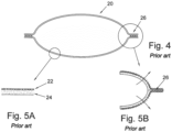
- a conventional lifejacket uses a single layer of material 20 that consists of a textile supporting sheet 22 (for example nylon or polyester) coated or laminated on the inside with a sheet 24 of flexible, air impermeable polymer such as neoprene or polyurethane.
- the coated two-layer material is typically stiff because of the relative thickness of the material and it is typically joined at its edges by welding or gluing the material together to form a seam 26.
- the resistance of the bladder to bursting from over pressure is dependent on the strength of the weld in peel and the strength of the welded or glued seam 26 is only as strong as the bonding of the polymer layer 24 to the supporting textile 22.
- the outer textile 22 when the outer textile 22 is coated with the polymer 24 its tear strength is greatly reduced and therefore a stronger and thicker textile must be used.
- Known lifejackets are provided with automatic inflators which are triggered automatically on contact with water.
- the inflator releases compressed gas from a cylinder in order to inflate the bladder of the lifejacket and provide buoyancy for the wearer.
- covers for inflatable lifejackets are designed by making an outer cover from stitched or welded panels of a textile that are shaped to conform to the overall shape of the bladder when it is deflated.
- the cover is closed over the bladder by a zipper or Velcro ® or press studs etc. built into the cover such that when the bladder is filled with gas from the inflation system the pressure of the gas inside the cover will open the zipper or Velcro or press studs and allow the bladder to expand outwards.
- Such arrangements are liable to damage and wear and are expensive to manufacture.
- the embodiments of the present invention seek to address one or more disadvantages of these known aspects of survival systems.
- a personal survival system as defined in claim 1.
- Optional features are specified in the dependent claims.
- the mounting system may comprise a fabric support or rigid frame or a garment.
- the inflation system may be mounted at a position that is more likely to be fully immersed in water in an emergency than the inflatable chamber, such as at or near the waist.
- the inflatable chamber may be configured to be mounted on the upper body of the wearer - such as the shoulders, neck and/or chest.
- the chamber may have a horse-shoe shape for fitting around the back of wearer's neck and resting against the wearer's chest.
- Two or more inflatable chambers may be provided.
- the inflation system may comprise a compressed gas container and/or an activation mechanism for triggering inflation.
- a lifejacket as shown in Figures 6 , 7A and 7B , or small single seat liferaft is modified such that, instead of the inflation system being directly mounted onto the buoyancy-providing bladder as described above in relation to Figure 1 to 3 , it is remote from the bladder and connected to it by a flexible tube through which the compressed gas can pass from the inflation system into the bladder.
- the inflation system 31 include a compressed gas cylinder 5 and an activation mechanism 7, similar to the known arrangement. When activated, compressed gas from the cylinder 5 passes through a valve 11 into a flexible tube 35 from where it is passed to the bladder 9 in order to inflate the bladder 9.
- the inflation system can be activated manually, in accordance with the invention, (by pulling on the lever 13) or automatically by a water activated device 15.
- inflators 31 In the drawings of this arrangement two inflators 31 are shown. However, there may be one inflator or more than two inflators.
- the inflator or inflators 31 may be mounted in a pocket that is attached to a harness, belt or jacket/vest of the wearer. The pocket is indicated by dashed lines 37 in the drawings.
- the arrangement allows the heavy, bulky and hard inflation system 31 to be mounted onto the wearer in a position that is better for the wearer and causes less obstruction and interference to the wearer's memorability and comfort.
- the wear on the bladder 9 may be greatly reduced by having the inflation system 31 remote to the bladder 9.
- FIGS 8A and 8B show in more detail how the inflation system 31 is connected to the bladder 9.
- inflation systems 31 need to be regularly checked and serviced as they contain pressurised gas and this process normally requires the lifejacket 33 to be unpacked and the inflation system 31 removed for servicing.
- the inflation system 31 can be easily detached for inspection and servicing without the need tom unpack the bladder 9.
- a further benefit of the remote inflation system 31 is that it can be mounted in a position whereby the (automatic) water activation part 15 of the inflation system 31 can be positioned lower on the wearer's body, as shown in Figures 9A and 9B , so that it ensures it will be fully immersed when the wearer falls into the water. This should be contrasted with the known arrangement described above in relation to Figures 3A and B .
- the inflation system may, e.g., be mounted at or near the waist of the wearer.
- the lifejacket bladder 9 may be contained in a cover and/or is incorporated into a survival vest or harness or ballistic protection vest or garment.
- the remote inflation system 31 may be either housed in a pocket on the garment or is contained in its own packet that can be attached to the vest or garment in a suitable position.
- the bladder 9 (and lifejacket 33) may remain in substantially the same position before and after inflation.
- the bladder 9 (and lifejacket 33) located on the body of the wearer by any suitable means, such as by being shaped to pass around the neck of the wearer and/or having a chest strap.
- Bladder 9 (and lifejacket 33) are mounted in deployment position prior to inflation (rather than being moved position by as a result of inflation). This may allow better (semi-permanent) location of the bladder 9 (and lifejacket 33) and provide more rapid deployment.
- the bladder 9 (and lifejacket 33) may be located by a rigid or partially rigid frame so that they remain in substantially the same position before and after inflation.
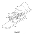
- Figures 20 and 20A show an alternative arrangement of an inflation system.
- the inflation system 31 includes a compressed gas cylinder 5 and an activation mechanism 7, similar to the known arrangement.
- compressed gas from the cylinder 5 passes into a tube 35 from where it is passed to the bladder 9 in order to inflate the bladder 9.
- the inflation system is activated manually by pulling on the lever 13, which moves spring-loaded piercer 14 to pierce a membrane of the gas cylinder 35 to release the gas.
- An indicator clip 16 provides a visual indication of whether the inflation system 31 has been used.
- a connector 17 for a further tube for transfer is optionally provided.
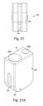
- the activation mechanism 7 is provided in a housing 20, shown in more detail in Figures 21A to 2 .
- the housing 20 has a top surface 21 with a first opening 22A to receive the gas cylinder 5 and a second opening 22B to receive the tube 35.
- the bottom surface 23 has a recess 24 formed therein that extends into at least one sidewall. The recess accommodates the moveable lever 13.
- a rear surface of the housing 20 is fixed to a mounting plate 100.
- Figure 22 shows an adaptor housing 25 so that a COTS (commercial off the shelf) inflation mechanism (manual or automatic/water-activated) can be adapted using this adaptor housing 25 so that the gas flow is directed from the gas cylinder 5 into the flexible tube 35 (rather than conventionally going through a "D Post" into a bladder).
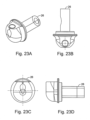
- Figures 23A-D show in more detail the adaptor 26 and Figures 24A-D show shows in more detail the cap nut 27.
- the outlet 28 of the adaptor 26 is connected to the tube 35 receives gas from the gas cylinder 35 via the adapter housing inlet 29.
- Figure 25 shows an alternative adaptor housing 25 so that a COTS (commercial off the shelf) inflation mechanism (manual or automatic/water-activated) can be adapted using this adaptor housing 25 so that the gas flow is directed from the gas cylinder 5 into the flexible tube 35.
- Figures 26A-C show in more detail the "banjo" adaptor 26 and Figures 27A-C show shows in more detail a D-post 30.
- the outlet 28 of the adaptor 26 is connected to the tube 35 receives gas from the gas cylinder 5 via the adapter housing inlet 29 and the D-post 30 that passes though the "banjo" adaptor 26 and into the adaptor housing 25.
- rear surface of the housing 20 is fixed to a mounting plate 100.
- the mounting plate 100 may include a recess 102 for accommodating the D-post 30 and the "banjo" adaptor 26, which recess also includes an opening through which the tube 35 passes.
- Figure 29 shows an inlet port 106 that fits onto the bladder 9 and to which the gas hose 35 is fitted.
- the flange 110 may be coupled to the surface of the bladder 9 so as to provide a fluid tight connection between the tube 35 and the bladder 9.
- This arrangement may use the inflation system of the second arrangement, below, and may additionally or alternatively house the inflation system in sealable chamber as described in relation to the third arrangement, below.
- a textile outer layer 52 may be formed of two sheets of material that are stitched together.
- An upper sheet of material 53A has an outer surface 57A and an inner surface 57B.
- the lower sheet of material 53B has an outer surface 58A and an inner surface 58B.
- the sheets 53A and 53B are connected at an edge region 59 of each of the sheets so that the distal inner surface of one of the sheets overlaps the distal outer surface of the other one of the sheets, the distal surfaces being stitched together, as indicated at 61.
- the distal inner surface 57B of the upper layer 57A is positioned to face the distal portion of the outer surface of the lower layer 53B, these layers being held in contact by the stitching 61.
- the bladder 9 is formed by two sheets 54 or flexible air impermeable material. The two sheets are joined by a weld.
- the outer textile 52 can be stitched (in sheer) around its edge and this creates a much stronger seam than the welding.
- the bladder 9 is made to be oversize or made from a polymer that can stretch and so the welded edge 56 never comes under tension, as shown in Figures 10A-C .
- the bladder 9 may be of generally the same shape as the outer textile 52, the bladder 9 may be of generally larger size.
- the bladder 9 may be made of a sufficiently large size so that, when inflated within the outer textile 52, the bladder 9 fills the internal volume of the outer textile 52 without any stretching of the bladder 9 occurring, and the tension is taken up by the outer textile 52. If the bladder 9 is made oversized, the bladder 9 may be made of an inextensible and/or inelastic material. It is advantageous for the tension to be taken up by the outer textile 52, as it is stronger than the bladder 9.
- the outer textile layer 52 is made from a lightweight "ripstop" material and is coated with a lubricant such as silicone. This produces an extremely strong material with high tear strength, and also, because the surface has a very low surface friction, the inner polymer layer will slide easily over it which results in a very compact lifejacket.
- Ripstop fabrics are woven fabrics, e.g. made of nylon, using a special reinforcing technique that makes them resistant to tearing and ripping. During weaving, relatively thick reinforcement threads are interwoven at regular intervals in a crosshatch pattern. The intervals are typically 5 to 8 mm. Thin and lightweight ripstop fabrics have a 3-dimensional structure due to the thicker threads being interwoven in thinner cloth.
- the third arrangement which is not the subject-matter of the claims, relates to the use of a water protected inflator.
- FIG 11 shows an example lifejacket 3 according to a third arrangement.
- the lifejacket 3 includes an inflator that is contains in a selectively sealable chamber 73 formed in the lifejacket 3, the chamber being selectively sealable by operation of a zipper 70.
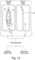
- the operation of the zipper is shown in Figure 12 .
- the zipper 70 is open the inflator 71 is exposed, and so if the lifejacket 3 is immersed in water the automatic inflator 71 will be triggered.
- the inflator 71 is not exposed and is sealed within a fluid-tight chamber 73 in the lifejacket 3.
- the inflator 71 When the zipper 70 is closed, the inflator 71 is not exposed to the environment outside the chamber, and so if the lifejacket 3 is immersed in water, the inflator will not automatically trigger. Thus, the lifejacket has an "automatic" inflation mode and a “manual” inflation mode.
- the chamber 73 may be attached to the bladder 9 and surrounds the gas cylinder 5, the release mechanism 75 and the piercing spike 14.
- the chamber 73 may be completely or partially formed integrally with the bladder 9 that provides buoyancy to the lifejacket 3.
- the chamber 73 may be completely or partially formed from the same material as the bladder 9 that provides buoyancy to the lifejacket 3.
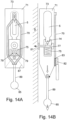
- Figure 13 shows the zipper 70 in a closed state
- Figure 14 shows the zipper 70 in an open state.
- the inflator 71 comprises a compressed gas container 5. Compressed gas is released from the container 5 by movement of the spring loaded piercing spike 14. The spring loaded piercing spike 14 is held apart from the container 5, against the action of the spring by an automatic release 75, that on significant contact with water, releases the spring loaded piercing spike 74 to pierce the seal of the container 5 to release the compressed gas.
- the automatic release may comprise a compressed salt pellet (such as one available from Halkey Roberts), a paper cartridge (such as one available from United Moulders) or a paper element protected by a hydrostatic valve (such as available from Hammar).
- a compressed salt pellet such as one available from Halkey Roberts
- a paper cartridge such as one available from United Moulders
- a hydrostatic valve such as available from Hammar
- the gas from the container 5 flows along conduit 77 via an inlet valve 81 into the bladder 9 of the lifejacket 3 in order to inflate the lifejacket.
- Figure 14 shows the zipper 70 in an open state.
- water will flow into the chamber 71 and will reach the automatic actuator 75, as indicated by arrow 79, and will cause release of the spring-loaded piercing pin 14 to puncture the seal of the container 5 in order to release the compressed gas, as indicated by the arrow 81.
- the zipper 70 slider may be fitted with a device 83 to ensure that it is fully closed.
- a device 83 may be an indicator attached to a press stud or an electronic "tag" that gives a signal when closed.
- the zipper slider is designated 82 in the drawings.
- Manual inflation of the bladder 9 may be required when the zipper is closed (and automatic operation is deactivated) or at any time when a wearer wishes to pre-inflate the bladder, such as when the wearer knows that they are about to enter water.
- a pull knob 85 provided for this purpose for operation by the wearer (or other personal).
- a reverse fold 87 may be formed in the chamber 73 whereby the pull knob 85 chord 89 is sealed onto the chamber 73.
- Other ways of releasing the manual pull knob 85 may be used, such as by tearing a seal or pulling out a plug.
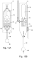
- Figures 15 and 16 correspond generally to Figures 13 and 14 , but show the water protected inflator arrangement used in combination with the remote inflation system of the embodiment.
- the piercing spike 14 pierces the seal of the compressed gas container 5
- the gas flows along the conduit 77 and then along the tube 35 to the bladder 9, as described in relation to the embodiment.
- FIG. 15 and 16 show how the waterproof pocket can be used with the water protected inflator concept.
- the ability of the inflation system to be converted from manual to automatic (water activated) has already been described, but the benefit with the remote inflation system is enhanced.
- the fourth arrangement which is not the subject-matter of the claims, relates to the construction of the outer cover.
- covers for inflatable lifejackets are designed by making an outer cover from stitched or welded panels of a textile that are shaped to conform to the overall shape of the bladder when it is deflated Figures 3A and 3B .
- Figure 18 shows the construction of such a cover in more detail.
- the cover 90 is made from a fabric or a plastic reinforced with a textile and is made to be a shape to conform to the wearers neck and torso. It is usually made by seaming together cut panels of the cover material. 91 is a typical seam.
- the cover is closed by a zipper 92, or by Velcro or press studs or a combination. If a zipper is used it is usual to incorporate a short lengthy of the zipper without the "teeth" such that when the bladder is inflated a section of the bladder will begin to open out and then the zipper "peels open” this is known as a "burst" zipper.
- Figure 8A and 8B show how the cover opens to allow the bladder to become fully inflated.
- the cover is closed over the bladder by a zipper or Velcro ® or press studs etc. built into the cover such that when the bladder is filled with gas from the inflation system the pressure of the gas inside the cover will open the zipper or Velcro or press studs and allow the bladder to expand outwards.
- a moulded cover constructed from a flexible polymer is used as an alternative to the known panels of material joined together.
- the cover is seamless and has a number of benefits.
- the smooth moulded outer cover is less liable to damage and wear and is cheaper to manufacture.
- the closure of the moulded cover can be by use of a "tongue and groove seam” like a "ziplock bag”.
- Figure 19 shows the cross section through the packed lifejacket.
- the moulded "seamless cover 93 is closed by a "tongue and groove” or “ziplock” type seal. This closure is designed to be strong enough not to open in use and rough handling etc. but will still open when the bladder begins to inflate.
Landscapes
- Engineering & Computer Science (AREA)
- Mechanical Engineering (AREA)
- Ocean & Marine Engineering (AREA)
- Health & Medical Sciences (AREA)
- General Health & Medical Sciences (AREA)
- Physical Education & Sports Medicine (AREA)
- Textile Engineering (AREA)
- Life Sciences & Earth Sciences (AREA)
- Oceanography (AREA)
- Professional, Industrial, Or Sporting Protective Garments (AREA)
- Revetment (AREA)
- Tents Or Canopies (AREA)
Description
- The present invention relates to survival systems, such as those for use in water and including an inflatable chamber - e.g. lifejackets and small single seat liferafts.
- As shown in
Figure 1A and B ,traditional inflation systems 1 are mounted directly onto thelifejacket 3 such that theinflation system 1, which consists of acompressed gas cylinder 5 and anactivation mechanism 7, is mounted directly onto the inflatable structure (bladder) 9 and the gas enters the inflatable structure through a valve 11 (typically a Schrader valve), as shown inFigure 2 . Theinflation system 1 can be activated manually (by pulling on a lever 13) or automatically by a water activateddevice 15 acting on apiercing pin 14. - The
inflation system 1 is typically many times the weight of thebladder 9 and cover, and is bulky and hard. In alifejacket 3, for example worn by a pilot or aircrew, the inflation system is included in the cover that containers thebladder 9. The additional weight and bulk of theinflation system 1 is a hindrance to the wearer as the position of thelifejacket 3 on the chest, as shown inFigures 1A and 1B , interferes with the many other items of equipment worn in this area and also with a harness system if worn. Additionally, the weight of theinflation system 1 in that position on the chest, when the pilot is experiencing acceleration, is increased which may further interfere with the pilot's breathing etc. - Additionally the inflation system, because it is hard and heavy, causes wear of the relatively delicate bladder system.
- When the wearer is wearing bulky and buoyant clothing or an immersion garment it is possible that the
inflation system 1, when it is mounted on the wearer, will remain above the water as shown inFigures 3A and 3B , and not activate which could lead to the wearer drowning. -
US6231411B1 discloses a "fashionable" life saving device in the form of e.g. shorts to disguise inflatable chambers, a gas canister and safety devices including a manual inflation tube. When inflated, the chambers move and rest under the user's arms, but are attached to his waist or the lower part of his body. -
WO2014083210A1 to a marine work and survival suit comprising a garment including a multi-layer fabric that covers all of the person's body and his/her upper and lower extremities, passive flotation elements and complementary thermal protection and flotation means that are automatically activated in man overboard (MOB) situations. The complementary flotation means comprise at least one complementary flotation volume, a compressed gas cartridge for inflating the complementary flotation volume through a flexible tube and a pyrotechnic device for blasting the gas cartridge. The pyrotechnic device is activated using electronic means comprising an electronic circuit board for controlling the suit, power supply batteries, at least two pairs of pressure sensors, and at least two pairs of conductivity sensors distributed on the surface of the suit - Another example of such a know life saving device is disclosed in
JP H09 301272 - As shown in
Figures 4, 5A, and 5B , a conventional lifejacket uses a single layer ofmaterial 20 that consists of a textile supporting sheet 22 (for example nylon or polyester) coated or laminated on the inside with asheet 24 of flexible, air impermeable polymer such as neoprene or polyurethane. The coated two-layer material is typically stiff because of the relative thickness of the material and it is typically joined at its edges by welding or gluing the material together to form aseam 26. The resistance of the bladder to bursting from over pressure is dependent on the strength of the weld in peel and the strength of the welded or gluedseam 26 is only as strong as the bonding of thepolymer layer 24 to the supportingtextile 22. Furthermore, when theouter textile 22 is coated with thepolymer 24 its tear strength is greatly reduced and therefore a stronger and thicker textile must be used. - Known lifejackets are provided with automatic inflators which are triggered automatically on contact with water. The inflator releases compressed gas from a cylinder in order to inflate the bladder of the lifejacket and provide buoyancy for the wearer.
- It can be advantageous to disable the automatic inflator in certain situations when there is a risk that the inflators will be exposed to moisture or water but when it would be undesirable for the lifejacket to inflate. Special forces for example may wish to disable automatic inflation during covert operation or when swimming, but at other times will wish to have the automatic inflation facility activated - such as when boarding a vessel.
- Known arrangements provide a cap or plug that seals off an automatic inflator by preventing water entering a chamber. Such known arrangements have the disadvantage of requiring an additional, separate part, which can be fiddly to operate and difficult to fit.
- Typically covers for inflatable lifejackets are designed by making an outer cover from stitched or welded panels of a textile that are shaped to conform to the overall shape of the bladder when it is deflated. The cover is closed over the bladder by a zipper or Velcro® or press studs etc. built into the cover such that when the bladder is filled with gas from the inflation system the pressure of the gas inside the cover will open the zipper or Velcro or press studs and allow the bladder to expand outwards. Such arrangements are liable to damage and wear and are expensive to manufacture.
- The embodiments of the present invention seek to address one or more disadvantages of these known aspects of survival systems.
- According to a first aspect of the invention, there is provided a personal survival system as defined in
claim 1. Optional features are specified in the dependent claims. - The mounting system may comprise a fabric support or rigid frame or a garment.
- The inflation system may be mounted at a position that is more likely to be fully immersed in water in an emergency than the inflatable chamber, such as at or near the waist.
- The inflatable chamber may be configured to be mounted on the upper body of the wearer - such as the shoulders, neck and/or chest. The chamber may have a horse-shoe shape for fitting around the back of wearer's neck and resting against the wearer's chest.
- Two or more inflatable chambers may be provided.
- The inflation system may comprise a compressed gas container and/or an activation mechanism for triggering inflation.
- For a better understanding of the present invention embodiments will now be described by way of example, with reference to the accompanying drawings, in which:
-
Figure 1A shows a front elevation of a known lifejacket and inflation system worn by a wearer; -
Figure 1B shows a side elevation of the known lifejacket and inflation system ofFigure 1A ; -
Figure 2 shows a partial cross-sectional view of the inflator and bladder of the lifejacket ofFigures 1A and 1B ; -
Figure 3A shows a front elevational view of the known lifejacket when the wearer is partially immersed in water; -
Figure 3B shows a side elevation of the partially immersed wearer corresponding toFigure 3A ; -
Figure 4 shows a cross-sectional view taken of the inflatable chamber of the known lifejacket; -
Figure 5A shows a close up detailed view of the material forming the layer of the inflator chamber ofFigure 4 ; -
Figure 5B shows an enlarged detailed view of the inflated chamber at a seam region; -
Figure 6 shows a partial cross-sectional view of an inflation system; -
Figure 7A shows a front elevation of a lifejacket incorporating the inflation system; -
Figure 7B shows a side elevation corresponding to the front elevation ofFigure 7A ; -
Figure 8A shows a part cross-sectional side elevational view of a lifejacket when in an inflated state; and -
Figure 8B shows a view corresponding to that ofFigure 8A prior to inflation of the lifejacket; -
Figure 9A shows a front elevation of a lifejacket in which the wearer is partially immersed in water; -
Figure 9B shows a side elevation corresponding to the front elevation ofFigure 9A ; -
Figure 10A shows a cross-sectional view of an inflatable chamber according to a second arrangement, which is not the subject-matter of the claims; -
Figure 10B shows an enlarged detailed view of the layers of the inflatable chamber according to the second arrangement; -
Figure 10C shows an enlarged view of the inflatable chamber where the upper and lower layers are connected together; -
Figure 11 shows a front elevational view of a lifejacket having a selectively sealable chamber for housing an inflator in accordance with a third arrangement, which is not the subject-matter of the claims; -
Figure 12 shows a zipper of the selectively sealable chamber in an open and closed position (automatic mode and manual mode) ; -
Figure 13A shows a front elevational detailed view of the zipper and chamber of the third arrangement with the zipper of the selectively sealable chamber closed; -
Figure 13B shows a partial cross-sectional side elevational view of the third arrangement with the zipper of the selectively sealable chamber closed; -
Figures 14A and 14B show views corresponding toFigures 13A and 13B , but with the zipper open; -
Figures 15A and 15B correspond toFigures 14A and 14B , but with the inflator mounted remotely from the bladder; -
Figures 16A and 16B correspond toFigures 13A and 13B but with the inflator remote from the bladder; -
Figure 18 shows a cross-section X-X of the conventional cover illustrated inFig. 3A and 3B ; -
Figure 19 shows an example moulded seamless cover; -
Figure 20 shows a perspective view of a modified inflation system according to an embodiment of the invention; -
Figure 20A shows a partial enlarged view ofFigure 20 ; -
Figure 21 shoes a bottom view of the housing of the inflation system according ofFigure 20 ; -
Figure 21A shoes a perspective view of the housing of the inflation system according ofFigure 20 ; -
Figure 22 shows a perspective view of a another modified inflation system according to an embodiment of the invention; -
Figure 23A shoes a perspective view of the adaptor of the inflation system according ofFigure 22 ; -
Figure 23B shows a top view of the adaptor of the inflation system according ofFigure 22 ; -
Figure 23C shows a front view of the adaptor of the inflation system according ofFigure 22 ; -
Figure 23D shoes a side view of the adaptor of the inflation system according ofFigure 22 ; -
Figure 24A shoes a perspective view of the cap nut of the inflation system according ofFigure 22 ; -
Figure 24B shows a top view of the cap nut of the inflation system according ofFigure 22 ; -
Figure 24C shows a front view of the cap nut of the inflation system according ofFigure 22 ; -
Figure 24D shoes a side view of the cap nut of the inflation system according ofFigure 22 ; -
Figure 25 shows a perspective view of a another modified inflation system; -
Figure 26A shoes a perspective view of the adaptor of the inflation system according ofFigure 25 ; -
Figure 26B shows a side view of the adaptor of the inflation system according ofFigure 25 ; -
Figure 26C shows a cross-sectional view of the adaptor of the inflation system according ofFigure 25 ; -
Figure 27A shoes a perspective view of the D-post of the inflation system according ofFigure 25 ; -
Figure 27B shows a side view of the D-post of the inflation system according ofFigure 25 ; -
Figure 27C shows a cross-sectional view of the D-post of the inflation system according ofFigure 25 ; -
Figure 28 shoes a perspective view of the inflation system of the inflation system according ofFigure 25 on a mounting plate; and -
Figure 29 shows an inlet port that fits onto a bladder. - In the drawings, like elements are generally designated with the same reference sign.
- In this arrangement a lifejacket, as shown in
Figures 6 ,7A and 7B , or small single seat liferaft is modified such that, instead of the inflation system being directly mounted onto the buoyancy-providing bladder as described above in relation toFigure 1 to 3 , it is remote from the bladder and connected to it by a flexible tube through which the compressed gas can pass from the inflation system into the bladder. - The
inflation system 31 include acompressed gas cylinder 5 and anactivation mechanism 7, similar to the known arrangement. When activated, compressed gas from thecylinder 5 passes through avalve 11 into aflexible tube 35 from where it is passed to thebladder 9 in order to inflate thebladder 9. The inflation system can be activated manually, in accordance with the invention, (by pulling on the lever 13) or automatically by a water activateddevice 15. - In the drawings of this arrangement two
inflators 31 are shown. However, there may be one inflator or more than two inflators. The inflator orinflators 31 may be mounted in a pocket that is attached to a harness, belt or jacket/vest of the wearer. The pocket is indicated by dashedlines 37 in the drawings. - The arrangement allows the heavy, bulky and
hard inflation system 31 to be mounted onto the wearer in a position that is better for the wearer and causes less obstruction and interference to the wearer's memorability and comfort. - The wear on the
bladder 9 may be greatly reduced by having theinflation system 31 remote to thebladder 9. -
Figures 8A and 8B show in more detail how theinflation system 31 is connected to thebladder 9. - When the
inflation system 31 is activated (either manually or automatically), compressed gas from thecylinder 5 is released by movement of the piercingpin 14. The compressed gas flows via thevalve 11 along thetube 35 and enters thebladder 9 of thelifejacket 33 via aconnector 39. Gas causes the bladder to inflate from the generally deflated state as shown inFigure 8B , as indicated byarrows 41, into the inflated state, as shown inFigure 8A , to fill thelifejacket 33 body and provide buoyancy for the wearer. - Another benefit is that
inflation systems 31 need to be regularly checked and serviced as they contain pressurised gas and this process normally requires thelifejacket 33 to be unpacked and theinflation system 31 removed for servicing. By using this arrangement, theinflation system 31 can be easily detached for inspection and servicing without the need tom unpack thebladder 9. - A further benefit of the
remote inflation system 31 is that it can be mounted in a position whereby the (automatic)water activation part 15 of theinflation system 31 can be positioned lower on the wearer's body, as shown inFigures 9A and 9B , so that it ensures it will be fully immersed when the wearer falls into the water. This should be contrasted with the known arrangement described above in relation toFigures 3A and B . The inflation system may, e.g., be mounted at or near the waist of the wearer. - The
lifejacket bladder 9 may be contained in a cover and/or is incorporated into a survival vest or harness or ballistic protection vest or garment. Theremote inflation system 31 may be either housed in a pocket on the garment or is contained in its own packet that can be attached to the vest or garment in a suitable position. - The bladder 9 (and lifejacket 33) may remain in substantially the same position before and after inflation. The bladder 9 (and lifejacket 33) located on the body of the wearer by any suitable means, such as by being shaped to pass around the neck of the wearer and/or having a chest strap. Bladder 9 (and lifejacket 33) are mounted in deployment position prior to inflation (rather than being moved position by as a result of inflation). This may allow better (semi-permanent) location of the bladder 9 (and lifejacket 33) and provide more rapid deployment. The bladder 9 (and lifejacket 33) may be located by a rigid or partially rigid frame so that they remain in substantially the same position before and after inflation.
-
Figures 20 and20A show an alternative arrangement of an inflation system. In this arrangement theinflation system 31 includes acompressed gas cylinder 5 and anactivation mechanism 7, similar to the known arrangement. When activated, compressed gas from thecylinder 5 passes into atube 35 from where it is passed to thebladder 9 in order to inflate thebladder 9. The inflation system is activated manually by pulling on thelever 13, which moves spring-loadedpiercer 14 to pierce a membrane of thegas cylinder 35 to release the gas. - An
indicator clip 16 provides a visual indication of whether theinflation system 31 has been used. Aconnector 17 for a further tube for transfer is optionally provided. - The
activation mechanism 7 is provided in ahousing 20, shown in more detail inFigures 21A to 2 . Thehousing 20 has atop surface 21 with afirst opening 22A to receive thegas cylinder 5 and asecond opening 22B to receive thetube 35. Thebottom surface 23 has arecess 24 formed therein that extends into at least one sidewall. The recess accommodates themoveable lever 13. A rear surface of thehousing 20 is fixed to a mountingplate 100. -
Figure 22 shows anadaptor housing 25 so that a COTS (commercial off the shelf) inflation mechanism (manual or automatic/water-activated) can be adapted using thisadaptor housing 25 so that the gas flow is directed from thegas cylinder 5 into the flexible tube 35 (rather than conventionally going through a "D Post" into a bladder).Figures 23A-D show in more detail theadaptor 26 andFigures 24A-D show shows in more detail thecap nut 27. Theoutlet 28 of theadaptor 26 is connected to thetube 35 receives gas from thegas cylinder 35 via theadapter housing inlet 29. -
Figure 25 shows analternative adaptor housing 25 so that a COTS (commercial off the shelf) inflation mechanism (manual or automatic/water-activated) can be adapted using thisadaptor housing 25 so that the gas flow is directed from thegas cylinder 5 into theflexible tube 35.Figures 26A-C show in more detail the "banjo"adaptor 26 andFigures 27A-C show shows in more detail a D-post 30. Theoutlet 28 of theadaptor 26 is connected to thetube 35 receives gas from thegas cylinder 5 via theadapter housing inlet 29 and the D-post 30 that passes though the "banjo"adaptor 26 and into theadaptor housing 25. As shown inFigure 28 rear surface of thehousing 20 is fixed to a mountingplate 100. The mountingplate 100 may include a recess 102 for accommodating the D-post 30 and the "banjo"adaptor 26, which recess also includes an opening through which thetube 35 passes. -
Figure 29 shows aninlet port 106 that fits onto thebladder 9 and to which thegas hose 35 is fitted. There is a small one-way check valve 108 fitted inside the flange 110 (to prevent back flow out of thebladder 9 if thetube 35 becomes detached or is punctured). Theflange 110 may be coupled to the surface of thebladder 9 so as to provide a fluid tight connection between thetube 35 and thebladder 9. - This arrangement may use the inflation system of the second arrangement, below, and may additionally or alternatively house the inflation system in sealable chamber as described in relation to the third arrangement, below.
- In this arrangement, which is not the subject-matter of the claims, instead of using a single layer of material that consists of a textile supporting sheet (for example nylon or polyester) coated or laminated on the inside with a sheet of flexible air impermeable polymer such as neoprene or polyurethane as described above with reference to
Figures 4 and 5A-B , the two separate layers are provided (i.e. a textile outer layer and the separate inner polymer layer). - The use of two separate layers to make a bladder, results in a bladder construction that is lighter, more compact when packed and stronger.
- As shown in
Figures 10A-C , a textile outer layer 52 (for example nylon or polyester) may be formed of two sheets of material that are stitched together. An upper sheet ofmaterial 53A has anouter surface 57A and aninner surface 57B. The lower sheet ofmaterial 53B has anouter surface 58A and aninner surface 58B. Thesheets edge region 59 of each of the sheets so that the distal inner surface of one of the sheets overlaps the distal outer surface of the other one of the sheets, the distal surfaces being stitched together, as indicated at 61. In the arrangement shown the distalinner surface 57B of theupper layer 57A is positioned to face the distal portion of the outer surface of thelower layer 53B, these layers being held in contact by thestitching 61. - The
bladder 9 is formed by twosheets 54 or flexible air impermeable material. The two sheets are joined by a weld. - In this arrangement the
outer textile 52 can be stitched (in sheer) around its edge and this creates a much stronger seam than the welding. Thebladder 9 is made to be oversize or made from a polymer that can stretch and so the weldededge 56 never comes under tension, as shown inFigures 10A-C . Although thebladder 9 may be of generally the same shape as theouter textile 52, thebladder 9 may be of generally larger size. Thebladder 9 may be made of a sufficiently large size so that, when inflated within theouter textile 52, thebladder 9 fills the internal volume of theouter textile 52 without any stretching of thebladder 9 occurring, and the tension is taken up by theouter textile 52. If thebladder 9 is made oversized, thebladder 9 may be made of an inextensible and/or inelastic material. It is advantageous for the tension to be taken up by theouter textile 52, as it is stronger than thebladder 9. - Preferably, the
outer textile layer 52 is made from a lightweight "ripstop" material and is coated with a lubricant such as silicone. This produces an extremely strong material with high tear strength, and also, because the surface has a very low surface friction, the inner polymer layer will slide easily over it which results in a very compact lifejacket. - Ripstop fabrics are woven fabrics, e.g. made of nylon, using a special reinforcing technique that makes them resistant to tearing and ripping. During weaving, relatively thick reinforcement threads are interwoven at regular intervals in a crosshatch pattern. The intervals are typically 5 to 8 mm. Thin and lightweight ripstop fabrics have a 3-dimensional structure due to the thicker threads being interwoven in thinner cloth.
- The third arrangement, which is not the subject-matter of the claims, relates to the use of a water protected inflator.
-
Figure 11 shows anexample lifejacket 3 according to a third arrangement. Thelifejacket 3 includes an inflator that is contains in a selectivelysealable chamber 73 formed in thelifejacket 3, the chamber being selectively sealable by operation of azipper 70. The operation of the zipper is shown inFigure 12 . When thezipper 70 is open the inflator 71 is exposed, and so if thelifejacket 3 is immersed in water theautomatic inflator 71 will be triggered. In contrast, when thezipper 70 is closed, theinflator 71 is not exposed and is sealed within a fluid-tight chamber 73 in thelifejacket 3. When thezipper 70 is closed, theinflator 71 is not exposed to the environment outside the chamber, and so if thelifejacket 3 is immersed in water, the inflator will not automatically trigger. Thus, the lifejacket has an "automatic" inflation mode and a "manual" inflation mode. - The
chamber 73 may be attached to thebladder 9 and surrounds thegas cylinder 5, therelease mechanism 75 and the piercingspike 14. Thechamber 73 may be completely or partially formed integrally with thebladder 9 that provides buoyancy to thelifejacket 3. Thechamber 73 may be completely or partially formed from the same material as thebladder 9 that provides buoyancy to thelifejacket 3. - The configuration and operation of the third arrangement will be described in more detail with reference to
Figures 13 and14 .Figure 13 shows thezipper 70 in a closed state, andFigure 14 shows thezipper 70 in an open state. - The inflator 71 comprises a
compressed gas container 5. Compressed gas is released from thecontainer 5 by movement of the spring loaded piercingspike 14. The spring loaded piercingspike 14 is held apart from thecontainer 5, against the action of the spring by anautomatic release 75, that on significant contact with water, releases the spring loaded piercing spike 74 to pierce the seal of thecontainer 5 to release the compressed gas. - The automatic release may comprise a compressed salt pellet (such as one available from Halkey Roberts), a paper cartridge (such as one available from United Moulders) or a paper element protected by a hydrostatic valve (such as available from Hammar).
- When the seal of the
container 5 is pierced by the piercingspike 14, the gas from thecontainer 5 flows alongconduit 77 via aninlet valve 81 into thebladder 9 of thelifejacket 3 in order to inflate the lifejacket. - In
Figure 13 thezipper 70 is closed, and so water cannot reach theautomatic actuator 75, and so inflation of thebladder 9 will not be automatically activated even if thelifejacket 3 is immersed in water. -
Figure 14 shows thezipper 70 in an open state. In this state water will flow into thechamber 71 and will reach theautomatic actuator 75, as indicated byarrow 79, and will cause release of the spring-loaded piercingpin 14 to puncture the seal of thecontainer 5 in order to release the compressed gas, as indicated by thearrow 81. - The
zipper 70 slider may be fitted with adevice 83 to ensure that it is fully closed. Such adevice 83 may be an indicator attached to a press stud or an electronic "tag" that gives a signal when closed. The zipper slider is designated 82 in the drawings. - There may be an indicator, similar to 83, at the upper (opened) end of the
zipper 70. - Manual inflation of the
bladder 9 may be required when the zipper is closed (and automatic operation is deactivated) or at any time when a wearer wishes to pre-inflate the bladder, such as when the wearer knows that they are about to enter water. Apull knob 85 provided for this purpose for operation by the wearer (or other personal). Areverse fold 87 may be formed in thechamber 73 whereby thepull knob 85chord 89 is sealed onto thechamber 73. Other ways of releasing themanual pull knob 85 may be used, such as by tearing a seal or pulling out a plug. -
Figures 15 and16 correspond generally toFigures 13 and14 , but show the water protected inflator arrangement used in combination with the remote inflation system of the embodiment. When the piercingspike 14 pierces the seal of the compressedgas container 5, the gas flows along theconduit 77 and then along thetube 35 to thebladder 9, as described in relation to the embodiment. - The embodiment of the remote inflation system lends itself to this waterproof pouch concept.
Figure 15 and16 show how the waterproof pocket can be used with the water protected inflator concept. The ability of the inflation system to be converted from manual to automatic (water activated) has already been described, but the benefit with the remote inflation system is enhanced. - The fourth arrangement, which is not the subject-matter of the claims, relates to the construction of the outer cover.
- As mentioned above, typically covers for inflatable lifejackets are designed by making an outer cover from stitched or welded panels of a textile that are shaped to conform to the overall shape of the bladder when it is deflated
Figures 3A and 3B .Figure 18 shows the construction of such a cover in more detail. - The
cover 90 is made from a fabric or a plastic reinforced with a textile and is made to be a shape to conform to the wearers neck and torso. It is usually made by seaming together cut panels of the cover material. 91 is a typical seam. The cover is closed by azipper 92, or by Velcro or press studs or a combination. If a zipper is used it is usual to incorporate a short lengthy of the zipper without the "teeth" such that when the bladder is inflated a section of the bladder will begin to open out and then the zipper "peels open" this is known as a "burst" zipper.Figure 8A and 8B show how the cover opens to allow the bladder to become fully inflated. The cover is closed over the bladder by a zipper or Velcro® or press studs etc. built into the cover such that when the bladder is filled with gas from the inflation system the pressure of the gas inside the cover will open the zipper or Velcro or press studs and allow the bladder to expand outwards. - In contrast, according to this arrangement, a moulded cover constructed from a flexible polymer is used as an alternative to the known panels of material joined together. The cover is seamless and has a number of benefits. The smooth moulded outer cover is less liable to damage and wear and is cheaper to manufacture. The closure of the moulded cover can be by use of a "tongue and groove seam" like a "ziplock bag".
Figure 19 shows the cross section through the packed lifejacket. The moulded "seamless cover 93 is closed by a "tongue and groove" or "ziplock" type seal. This closure is designed to be strong enough not to open in use and rough handling etc. but will still open when the bladder begins to inflate.
Claims (4)
- A personal survival system for use in water, including:an inflatable chamber (9),an inflation system (31) operable to inflate the inflatable chamber (9), and wherein the inflation system and the inflatable chamber are mountable on a wearer's body and the inflation system (31) is mountable separately from and remotely from the inflatable chamber (9),a tube (35) providing a fluid connection between the inflation system (31) and the inflatable chamber (9),a one-way check valve (108) provided to prevent back-flow out of the inflatable chamber (9),a mounting system configured to locate the inflation system separately from and remotely from the inflatable chamber so that they are spaced apart on a wearer's body at substantially the same positions prior to and after inflation of the inflatable chamber,characterised in that the inflation system (31) is manually operable and comprises a housing (20, 25) that is coupled to the tube (35), the housing (20, 25) being fixed to a mounting plate (100).
- The personal survival system of claim 1, wherein the inflation system (31) is mountable on the wearer's body at a position that is more likely to be fully immersed in water in an emergency than the inflatable chamber (9).
- The personal survival system of claim 1 or 2, wherein the inflation system (31) comprises a compressed gas container (5) and/or an activation mechanism (7).
- The personal survival system of claim 1, 2 or 3, wherein the inflation system (31) can be activated manually by pulling on a lever (13).
Applications Claiming Priority (2)
| Application Number | Priority Date | Filing Date | Title |
|---|---|---|---|
| GB1702609.7A GB2559773B (en) | 2017-02-17 | 2017-02-17 | Survival systems |
| PCT/EP2018/053820 WO2018149933A1 (en) | 2017-02-17 | 2018-02-15 | Survival systems |
Publications (2)
| Publication Number | Publication Date |
|---|---|
| EP3583025A1 EP3583025A1 (en) | 2019-12-25 |
| EP3583025B1 true EP3583025B1 (en) | 2025-02-26 |
Family
ID=58486958
Family Applications (1)
| Application Number | Title | Priority Date | Filing Date |
|---|---|---|---|
| EP18706694.9A Active EP3583025B1 (en) | 2017-02-17 | 2018-02-15 | Survival systems |
Country Status (7)
| Country | Link |
|---|---|
| US (1) | US11214342B2 (en) |
| EP (1) | EP3583025B1 (en) |
| AU (2) | AU2018221769B2 (en) |
| ES (1) | ES3027200T3 (en) |
| FI (1) | FI3583025T3 (en) |
| GB (2) | GB2559773B (en) |
| WO (1) | WO2018149933A1 (en) |
Families Citing this family (3)
| Publication number | Priority date | Publication date | Assignee | Title |
|---|---|---|---|---|
| CN110789692A (en) * | 2019-11-20 | 2020-02-14 | 常州机电职业技术学院 | Portable buoyancy device |
| GB2615742A (en) * | 2022-02-03 | 2023-08-23 | Survitec Group Ltd | Life preserver |
| US12509199B2 (en) * | 2022-02-28 | 2025-12-30 | G180, Llc | Personal flotation device |
Citations (2)
| Publication number | Priority date | Publication date | Assignee | Title |
|---|---|---|---|---|
| WO2014083210A1 (en) * | 2012-11-28 | 2014-06-05 | Aeromarine, S. L. | Marine work and survival suit |
| US20140213128A1 (en) * | 2013-01-31 | 2014-07-31 | Hugh Patrick Hughes | Inflatable swim vest |
Family Cites Families (23)
| Publication number | Priority date | Publication date | Assignee | Title |
|---|---|---|---|---|
| US874026A (en) * | 1907-08-27 | 1907-12-17 | Adolf Necker | Life-preserver. |
| US1960474A (en) * | 1931-12-08 | 1934-05-29 | Montague P Browne | Buoyant bathing device |
| US2842785A (en) * | 1954-05-07 | 1958-07-15 | William C Sieverts | Life jacket |
| US4416641A (en) * | 1981-08-28 | 1983-11-22 | East/West Industries, Inc. | Anti-exposure jacket |
| US4842562A (en) | 1988-01-28 | 1989-06-27 | Supal Mark L | Inflatable buoyancy belt |
| GB2277906B (en) * | 1993-04-26 | 1997-01-08 | Crewsaver Limited | Improvements relating to flotation devices |
| JP2912870B2 (en) * | 1996-05-13 | 1999-06-28 | 一二三 奈良部 | Lifesaving rescue equipment |
| GB9612733D0 (en) * | 1996-06-18 | 1996-08-21 | Int Safety Group Ltd | Improvements relating to life jackets |
| US6231411B1 (en) * | 2000-05-24 | 2001-05-15 | Alejandro Vinay | Fashionable emergency flotation aid |
| KR100442910B1 (en) * | 2002-01-10 | 2004-08-04 | 손양현 | Automatic life saving tube |
| US7033237B2 (en) * | 2003-05-26 | 2006-04-25 | The Life Belt S.R.L. | Inflatable safety apparatus |
| ITMI20031051A1 (en) | 2003-05-26 | 2004-11-27 | Vito Spagnuolo | INFLATABLE SECURITY APPARATUS |
| US7061040B2 (en) | 2003-11-14 | 2006-06-13 | United Microelectronics Corp. | Memory device |
| US7819714B2 (en) * | 2004-04-29 | 2010-10-26 | Irvin Aerospace Canada Limited | Water activated inflator for inflatable device and method of air deployment |
| US7937770B1 (en) | 2008-04-16 | 2011-05-10 | Hernandez Marcos | Inflatable swimsuit |
| CN202138521U (en) * | 2011-05-20 | 2012-02-08 | 吴宝良 | Double-layer inflatable article |
| US20130014310A1 (en) | 2011-07-15 | 2013-01-17 | Tang Tai Shun | Swimsuit with lifesaving device |
| US8911273B2 (en) * | 2012-08-29 | 2014-12-16 | Patagonia, Inc. | Watersports inflation vest |
| AU2013203831B2 (en) * | 2012-11-01 | 2015-06-04 | Thf Innovation Pty Ltd | A personal protection system including a garment with body armour and a personal flotation device |
| US9481144B1 (en) * | 2015-03-02 | 2016-11-01 | Air Cruisers Company, LLC | Nonwoven flexible composites |
| AU2016235235B2 (en) * | 2015-03-23 | 2019-03-14 | Halkey-Roberts Corporation | Indicator for manual inflator |
| US10745130B2 (en) * | 2015-07-28 | 2020-08-18 | The Skylife Company, Inc. | Container for aerial delivery |
| US10182662B2 (en) * | 2016-05-04 | 2019-01-22 | Dreamwell, Ltd. | Adjustable comfort mattress system and processes |
-
2017
- 2017-02-17 GB GB1702609.7A patent/GB2559773B/en active Active
-
2018
- 2018-02-15 GB GB1911678.9A patent/GB2573474B/en active Active
- 2018-02-15 WO PCT/EP2018/053820 patent/WO2018149933A1/en not_active Ceased
- 2018-02-15 FI FIEP18706694.9T patent/FI3583025T3/en active
- 2018-02-15 US US16/486,801 patent/US11214342B2/en active Active
- 2018-02-15 ES ES18706694T patent/ES3027200T3/en active Active
- 2018-02-15 AU AU2018221769A patent/AU2018221769B2/en active Active
- 2018-02-15 EP EP18706694.9A patent/EP3583025B1/en active Active
-
2024
- 2024-04-19 AU AU2024202591A patent/AU2024202591A1/en active Pending
Patent Citations (2)
| Publication number | Priority date | Publication date | Assignee | Title |
|---|---|---|---|---|
| WO2014083210A1 (en) * | 2012-11-28 | 2014-06-05 | Aeromarine, S. L. | Marine work and survival suit |
| US20140213128A1 (en) * | 2013-01-31 | 2014-07-31 | Hugh Patrick Hughes | Inflatable swim vest |
Also Published As
| Publication number | Publication date |
|---|---|
| GB201702609D0 (en) | 2017-04-05 |
| US20200031440A1 (en) | 2020-01-30 |
| GB2559773A (en) | 2018-08-22 |
| FI3583025T3 (en) | 2025-05-22 |
| ES3027200T3 (en) | 2025-06-13 |
| US11214342B2 (en) | 2022-01-04 |
| EP3583025A1 (en) | 2019-12-25 |
| GB2573474B (en) | 2021-10-06 |
| GB2559773B (en) | 2022-03-23 |
| AU2018221769B2 (en) | 2024-05-09 |
| AU2024202591A1 (en) | 2024-05-09 |
| AU2018221769A1 (en) | 2019-09-19 |
| GB201911678D0 (en) | 2019-10-02 |
| WO2018149933A1 (en) | 2018-08-23 |
| GB2573474A (en) | 2019-11-06 |
Similar Documents
| Publication | Publication Date | Title |
|---|---|---|
| US9869532B2 (en) | Maritime ballistic safety carrier | |
| AU2024202591A1 (en) | Survival systems | |
| US4324234A (en) | Dual chamber personal flotation device | |
| US5494469A (en) | Inflatable life vest | |
| US9802685B2 (en) | Flotation safety system | |
| EP1565077B1 (en) | Personal flotation device | |
| US6837764B2 (en) | Multi-chambered flotation device | |
| AU2002324525A1 (en) | Multi-chambered flotation device | |
| US2463641A (en) | Buoyant belt with wearing apparel | |
| JP3806574B2 (en) | Lifesaving waist bag | |
| GB2562756A (en) | A safety device | |
| US20250128799A1 (en) | Life preserver | |
| US9944368B1 (en) | Inflatable life raft assembly | |
| US20040029466A1 (en) | Life preserver | |
| KR102930352B1 (en) | Bulletproof suit with emergency flotation | |
| US20240359782A1 (en) | Flexible life-saving flotation device | |
| JP4118656B2 (en) | Automatic inflatable life jacket | |
| WO2018197718A1 (en) | Lifejacket | |
| GB2639872A (en) | Life-saving system | |
| JP2004090773A (en) | Always wear type life vest and buoyancy body for life vest | |
| KR20130012697A (en) | Life jacket having lifeboat |
Legal Events
| Date | Code | Title | Description |
|---|---|---|---|
| STAA | Information on the status of an ep patent application or granted ep patent |
Free format text: STATUS: UNKNOWN |
|
| STAA | Information on the status of an ep patent application or granted ep patent |
Free format text: STATUS: THE INTERNATIONAL PUBLICATION HAS BEEN MADE |
|
| PUAI | Public reference made under article 153(3) epc to a published international application that has entered the european phase |
Free format text: ORIGINAL CODE: 0009012 |
|
| STAA | Information on the status of an ep patent application or granted ep patent |
Free format text: STATUS: REQUEST FOR EXAMINATION WAS MADE |
|
| 17P | Request for examination filed |
Effective date: 20190815 |
|
| AK | Designated contracting states |
Kind code of ref document: A1 Designated state(s): AL AT BE BG CH CY CZ DE DK EE ES FI FR GB GR HR HU IE IS IT LI LT LU LV MC MK MT NL NO PL PT RO RS SE SI SK SM TR |
|
| AX | Request for extension of the european patent |
Extension state: BA ME |
|
| DAV | Request for validation of the european patent (deleted) | ||
| DAX | Request for extension of the european patent (deleted) | ||
| STAA | Information on the status of an ep patent application or granted ep patent |
Free format text: STATUS: EXAMINATION IS IN PROGRESS |
|
| 17Q | First examination report despatched |
Effective date: 20200911 |
|
| GRAP | Despatch of communication of intention to grant a patent |
Free format text: ORIGINAL CODE: EPIDOSNIGR1 |
|
| STAA | Information on the status of an ep patent application or granted ep patent |
Free format text: STATUS: GRANT OF PATENT IS INTENDED |
|
| INTG | Intention to grant announced |
Effective date: 20240916 |
|
| GRAS | Grant fee paid |
Free format text: ORIGINAL CODE: EPIDOSNIGR3 |
|
| GRAA | (expected) grant |
Free format text: ORIGINAL CODE: 0009210 |
|
| STAA | Information on the status of an ep patent application or granted ep patent |
Free format text: STATUS: THE PATENT HAS BEEN GRANTED |
|
| RBV | Designated contracting states (corrected) |
Designated state(s): AL AT BE BG CH CY CZ DE DK EE ES FI FR GR HR HU IE IS IT LI LT LU LV MC MK MT NL NO PL PT RO RS SE SI SK SM TR |
|
| AK | Designated contracting states |
Kind code of ref document: B1 Designated state(s): AL AT BE BG CH CY CZ DE DK EE ES FI FR GR HR HU IE IS IT LI LT LU LV MC MK MT NL NO PL PT RO RS SE SI SK SM TR |
|
| REG | Reference to a national code |
Ref country code: CH Ref legal event code: EP |
|
| REG | Reference to a national code |
Ref country code: DE Ref legal event code: R096 Ref document number: 602018079548 Country of ref document: DE |
|
| REG | Reference to a national code |
Ref country code: IE Ref legal event code: FG4D |
|
| REG | Reference to a national code |
Ref country code: FI Ref legal event code: FGE |
|
| REG | Reference to a national code |
Ref country code: SE Ref legal event code: TRGR |
|
| REG | Reference to a national code |
Ref country code: ES Ref legal event code: FG2A Ref document number: 3027200 Country of ref document: ES Kind code of ref document: T3 Effective date: 20250613 |
|
| REG | Reference to a national code |
Ref country code: NL Ref legal event code: MP Effective date: 20250226 |
|
| PG25 | Lapsed in a contracting state [announced via postgrant information from national office to epo] |
Ref country code: RS Free format text: LAPSE BECAUSE OF FAILURE TO SUBMIT A TRANSLATION OF THE DESCRIPTION OR TO PAY THE FEE WITHIN THE PRESCRIBED TIME-LIMIT Effective date: 20250526 |
|
| PG25 | Lapsed in a contracting state [announced via postgrant information from national office to epo] |
Ref country code: PL Free format text: LAPSE BECAUSE OF FAILURE TO SUBMIT A TRANSLATION OF THE DESCRIPTION OR TO PAY THE FEE WITHIN THE PRESCRIBED TIME-LIMIT Effective date: 20250226 |
|
| REG | Reference to a national code |
Ref country code: LT Ref legal event code: MG9D |
|
| PG25 | Lapsed in a contracting state [announced via postgrant information from national office to epo] |
Ref country code: IS Free format text: LAPSE BECAUSE OF FAILURE TO SUBMIT A TRANSLATION OF THE DESCRIPTION OR TO PAY THE FEE WITHIN THE PRESCRIBED TIME-LIMIT Effective date: 20250626 |
|
| PG25 | Lapsed in a contracting state [announced via postgrant information from national office to epo] |
Ref country code: NL Free format text: LAPSE BECAUSE OF FAILURE TO SUBMIT A TRANSLATION OF THE DESCRIPTION OR TO PAY THE FEE WITHIN THE PRESCRIBED TIME-LIMIT Effective date: 20250226 |
|
| PG25 | Lapsed in a contracting state [announced via postgrant information from national office to epo] |
Ref country code: HR Free format text: LAPSE BECAUSE OF FAILURE TO SUBMIT A TRANSLATION OF THE DESCRIPTION OR TO PAY THE FEE WITHIN THE PRESCRIBED TIME-LIMIT Effective date: 20250226 |
|
| PG25 | Lapsed in a contracting state [announced via postgrant information from national office to epo] |
Ref country code: PT Free format text: LAPSE BECAUSE OF FAILURE TO SUBMIT A TRANSLATION OF THE DESCRIPTION OR TO PAY THE FEE WITHIN THE PRESCRIBED TIME-LIMIT Effective date: 20250626 Ref country code: LV Free format text: LAPSE BECAUSE OF FAILURE TO SUBMIT A TRANSLATION OF THE DESCRIPTION OR TO PAY THE FEE WITHIN THE PRESCRIBED TIME-LIMIT Effective date: 20250226 |
|
| PG25 | Lapsed in a contracting state [announced via postgrant information from national office to epo] |
Ref country code: GR Free format text: LAPSE BECAUSE OF FAILURE TO SUBMIT A TRANSLATION OF THE DESCRIPTION OR TO PAY THE FEE WITHIN THE PRESCRIBED TIME-LIMIT Effective date: 20250527 Ref country code: BG Free format text: LAPSE BECAUSE OF FAILURE TO SUBMIT A TRANSLATION OF THE DESCRIPTION OR TO PAY THE FEE WITHIN THE PRESCRIBED TIME-LIMIT Effective date: 20250226 |
|
| REG | Reference to a national code |
Ref country code: AT Ref legal event code: MK05 Ref document number: 1770421 Country of ref document: AT Kind code of ref document: T Effective date: 20250226 |
|
| PG25 | Lapsed in a contracting state [announced via postgrant information from national office to epo] |
Ref country code: SM Free format text: LAPSE BECAUSE OF FAILURE TO SUBMIT A TRANSLATION OF THE DESCRIPTION OR TO PAY THE FEE WITHIN THE PRESCRIBED TIME-LIMIT Effective date: 20250226 |
|
| PG25 | Lapsed in a contracting state [announced via postgrant information from national office to epo] |
Ref country code: DK Free format text: LAPSE BECAUSE OF FAILURE TO SUBMIT A TRANSLATION OF THE DESCRIPTION OR TO PAY THE FEE WITHIN THE PRESCRIBED TIME-LIMIT Effective date: 20250226 |
|
| PG25 | Lapsed in a contracting state [announced via postgrant information from national office to epo] |
Ref country code: AT Free format text: LAPSE BECAUSE OF FAILURE TO SUBMIT A TRANSLATION OF THE DESCRIPTION OR TO PAY THE FEE WITHIN THE PRESCRIBED TIME-LIMIT Effective date: 20250226 |
|
| PG25 | Lapsed in a contracting state [announced via postgrant information from national office to epo] |
Ref country code: EE Free format text: LAPSE BECAUSE OF FAILURE TO SUBMIT A TRANSLATION OF THE DESCRIPTION OR TO PAY THE FEE WITHIN THE PRESCRIBED TIME-LIMIT Effective date: 20250226 Ref country code: CZ Free format text: LAPSE BECAUSE OF FAILURE TO SUBMIT A TRANSLATION OF THE DESCRIPTION OR TO PAY THE FEE WITHIN THE PRESCRIBED TIME-LIMIT Effective date: 20250226 |
|
| PG25 | Lapsed in a contracting state [announced via postgrant information from national office to epo] |
Ref country code: RO Free format text: LAPSE BECAUSE OF FAILURE TO SUBMIT A TRANSLATION OF THE DESCRIPTION OR TO PAY THE FEE WITHIN THE PRESCRIBED TIME-LIMIT Effective date: 20250226 |
|
| PG25 | Lapsed in a contracting state [announced via postgrant information from national office to epo] |
Ref country code: SK Free format text: LAPSE BECAUSE OF FAILURE TO SUBMIT A TRANSLATION OF THE DESCRIPTION OR TO PAY THE FEE WITHIN THE PRESCRIBED TIME-LIMIT Effective date: 20250226 |
|
| REG | Reference to a national code |
Ref country code: DE Ref legal event code: R097 Ref document number: 602018079548 Country of ref document: DE |
|
| PLBE | No opposition filed within time limit |
Free format text: ORIGINAL CODE: 0009261 |
|
| STAA | Information on the status of an ep patent application or granted ep patent |
Free format text: STATUS: NO OPPOSITION FILED WITHIN TIME LIMIT |
|
| 26N | No opposition filed |
Effective date: 20251127 |
|
| PGFP | Annual fee paid to national office [announced via postgrant information from national office to epo] |
Ref country code: SE Payment date: 20260227 Year of fee payment: 9 |
|
| PGFP | Annual fee paid to national office [announced via postgrant information from national office to epo] |
Ref country code: ES Payment date: 20260302 Year of fee payment: 9 |
|
| PGFP | Annual fee paid to national office [announced via postgrant information from national office to epo] |
Ref country code: DE Payment date: 20260227 Year of fee payment: 9 Ref country code: NO Payment date: 20260227 Year of fee payment: 9 |
|
| PGFP | Annual fee paid to national office [announced via postgrant information from national office to epo] |
Ref country code: FI Payment date: 20260225 Year of fee payment: 9 Ref country code: IT Payment date: 20260219 Year of fee payment: 9 |
|
| PGFP | Annual fee paid to national office [announced via postgrant information from national office to epo] |
Ref country code: FR Payment date: 20260225 Year of fee payment: 9 |