EP3582594B1 - Module locking apparatus, module, and electrical equipment - Google Patents
Module locking apparatus, module, and electrical equipment Download PDFInfo
- Publication number
- EP3582594B1 EP3582594B1 EP19180021.8A EP19180021A EP3582594B1 EP 3582594 B1 EP3582594 B1 EP 3582594B1 EP 19180021 A EP19180021 A EP 19180021A EP 3582594 B1 EP3582594 B1 EP 3582594B1
- Authority
- EP
- European Patent Office
- Prior art keywords
- module
- ejector lever
- tongue
- supporting base
- locking apparatus
- Prior art date
- Legal status (The legal status is an assumption and is not a legal conclusion. Google has not performed a legal analysis and makes no representation as to the accuracy of the status listed.)
- Active
Links
Images




Classifications
-
- H—ELECTRICITY
- H05—ELECTRIC TECHNIQUES NOT OTHERWISE PROVIDED FOR
- H05K—PRINTED CIRCUITS; CASINGS OR CONSTRUCTIONAL DETAILS OF ELECTRIC APPARATUS; MANUFACTURE OF ASSEMBLAGES OF ELECTRICAL COMPONENTS
- H05K7/00—Constructional details common to different types of electric apparatus
- H05K7/14—Mounting supporting structure in casing or on frame or rack
- H05K7/1485—Servers; Data center rooms, e.g. 19-inch computer racks
- H05K7/1487—Blade assemblies, e.g. blade cases or inner arrangements within a blade
-
- H—ELECTRICITY
- H05—ELECTRIC TECHNIQUES NOT OTHERWISE PROVIDED FOR
- H05K—PRINTED CIRCUITS; CASINGS OR CONSTRUCTIONAL DETAILS OF ELECTRIC APPARATUS; MANUFACTURE OF ASSEMBLAGES OF ELECTRICAL COMPONENTS
- H05K7/00—Constructional details common to different types of electric apparatus
- H05K7/14—Mounting supporting structure in casing or on frame or rack
- H05K7/1422—Printed circuit boards receptacles, e.g. stacked structures, electronic circuit modules or box like frames
-
- H—ELECTRICITY
- H05—ELECTRIC TECHNIQUES NOT OTHERWISE PROVIDED FOR
- H05K—PRINTED CIRCUITS; CASINGS OR CONSTRUCTIONAL DETAILS OF ELECTRIC APPARATUS; MANUFACTURE OF ASSEMBLAGES OF ELECTRICAL COMPONENTS
- H05K7/00—Constructional details common to different types of electric apparatus
- H05K7/14—Mounting supporting structure in casing or on frame or rack
- H05K7/1422—Printed circuit boards receptacles, e.g. stacked structures, electronic circuit modules or box like frames
- H05K7/1427—Housings
- H05K7/1432—Housings specially adapted for power drive units or power converters
-
- H—ELECTRICITY
- H05—ELECTRIC TECHNIQUES NOT OTHERWISE PROVIDED FOR
- H05K—PRINTED CIRCUITS; CASINGS OR CONSTRUCTIONAL DETAILS OF ELECTRIC APPARATUS; MANUFACTURE OF ASSEMBLAGES OF ELECTRICAL COMPONENTS
- H05K7/00—Constructional details common to different types of electric apparatus
- H05K7/14—Mounting supporting structure in casing or on frame or rack
- H05K7/1485—Servers; Data center rooms, e.g. 19-inch computer racks
- H05K7/1488—Cabinets therefor, e.g. chassis or racks or mechanical interfaces between blades and support structures
- H05K7/1492—Cabinets therefor, e.g. chassis or racks or mechanical interfaces between blades and support structures having electrical distribution arrangements, e.g. power supply or data communications
Definitions
- This application relates to the field of communications technologies, and in particular, to a module locking apparatus, a module, and electrical equipment.
- a communication power module In an existing communications cabinet, a communication power module is usually installed in a subrack inside the cabinet. When the communication power module is assembled or used, the communication power module usually needs to be pulled out of or pushed into the subrack. For ease of pulling out or pushing in the module, an ejector lever structure is usually designed on a panel of the module. After the module is inserted into the subrack, a fixing device is used to fix the module onto the subrack. Power density of a communications product is increasing, and utilization of product space in the module is increasingly high, and therefore an ejector lever needs to occupy less space, and have a more reliable fixing structure, a simpler assembly method, and an aesthetically attractive appearance.
- a module locking apparatus configured to lock a module onto a cabinet.
- the locking apparatus includes a casing and a supporting base that serves as a supporting apparatus, where the casing covers the supporting base, and space for accommodating main moving components of the locking apparatus is formed between the supporting base and the casing.
- the moving components include a tongue, an elastic component, and an ejector lever, where the tongue is located between the supporting base and the casing; one end of the tongue is rotatably connected to the supporting base, and the other end of the tongue is a free end; and a hook configured to engage with the cabinet is disposed on the free end.
- Unlocking is implemented by using the ejector lever.
- the ejector lever is rotatably connected to the supporting base, and can press the tongue to rotate in a direction away from the casing. When being rotated to a first specified position, the ejector lever presses the tongue to rotate to a position in which the tongue is disengaged from the cabinet, thereby implementing unlocking.
- a specific structure of the tongue includes a rotating shaft and a connecting plate connected to the rotating shaft.
- the rotating shaft is rotatably connected to the supporting base, and the hook is disposed at an end of the connecting plate away from the rotating shaft.
- the installed rotating shaft coordinates with the supporting base to make the tongue rotate relative to the supporting base, and the connecting plate is installed to generate a specific distance between the hook and the rotating shaft, ensuring a specific rotation distance for the hook when the tongue rotates, to lock onto and unlock from the cabinet.
- the elastic component is configured to push the tongue to rotate and enable the hook on the tongue to engage with the cabinet.
- the elastic component may be elastic components of different structure types.
- the elastic component is a rotary spring.
- the rotary spring is sleeved on the rotating shaft of the tongue, and two ends of the rotary spring press against the supporting base and the connecting plate, respectively, to push the tongue to rotate and provide force for the hook to engage with the cabinet.
- the elastic component may be an elastic sheet.
- One end of the elastic sheet is provided with a bent structure, and correspondingly, a mounting base is disposed on the supporting base. The bent structure may be clamped on the mounting base, to fasten the elastic sheet onto the supporting base.
- a surface, facing away from the supporting base, of the connecting plate is a pressing surface that coordinates with the ejector lever, and the pressing surface is a surface pressed when the ejector lever pushes the tongue to rotate.
- the pressing surface faces away from the supporting base, and the pressing surface is disposed in an inclined manner opposite to a first surface, facing the supporting base, of the connecting plate.
- a vertical distance between the pressing surface and the first surface gradually increases in a direction away from the rotating shaft. In this way, when the ejector lever is rotated, an effect of pushing the tongue to rotate can be improved.
- the ejector lever is a C-shaped ejector lever, and two ends of the ejector lever are a first end and a second end, respectively.
- the first end is used for pressing the pressing surface; and when the ejector lever is rotated to the second specified position, both the first end and the second end of the ejector lever are located in a notch, and a middle part of the ejector lever is exposed outside a side face that is of the supporting base and that is perpendicular to the casing.
- the exposed part makes it convenient to pull the ejector lever to rotate.
- a through hole that coordinates with the hook is disposed in the casing during installation of the casing. Pushed by the elastic component, the hook is exposed out of the through hole. When the ejector lever pushes the tongue, the hook moves back into the through hole.
- a module is provided.
- the module includes a module body and the locking apparatus, according to any implementation of the first aspect, fixedly connected to the module body.
- the elastic component is used to push the hook to lock the module and the cabinet together, and to implement unlocking, only the ejector lever needs to be pulled to press the hook down. It can be learned from the foregoing description that the operations during using of the module locking apparatus provided in the present application are simple: Only the ejector lever needs to be pulled to implement unlocking, and the module is pushed into the cabinet to implement locking.
- the tongue, the elastic component, and the ejector lever are all disposed on a side wall of the module, and only a part of the ejector lever is exposed out of a panel of the module. Compared with a module locking structure in the prior art, in this structure, an area occupied on the panel is reduced.
- the module further includes an outer casing covering the module body.
- the supporting base and the side wall of the module body are of an integrated structure, and the casing and the outer casing of the module body are of an integrated structure. In this way, the locking apparatus can be directly formed on the module body.
Landscapes
- Engineering & Computer Science (AREA)
- Microelectronics & Electronic Packaging (AREA)
- Computer Hardware Design (AREA)
- General Engineering & Computer Science (AREA)
- Casings For Electric Apparatus (AREA)
Description
- This application relates to the field of communications technologies, and in particular, to a module locking apparatus, a module, and electrical equipment.
- In an existing communications cabinet, a communication power module is usually installed in a subrack inside the cabinet. When the communication power module is assembled or used, the communication power module usually needs to be pulled out of or pushed into the subrack. For ease of pulling out or pushing in the module, an ejector lever structure is usually designed on a panel of the module. After the module is inserted into the subrack, a fixing device is used to fix the module onto the subrack. Power density of a communications product is increasing, and utilization of product space in the module is increasingly high, and therefore an ejector lever needs to occupy less space, and have a more reliable fixing structure, a simpler assembly method, and an aesthetically attractive appearance.
US 2013/044440 A1 describes locking systems for fitting and securing modules in a housing includes at least one module.
US 2013 / 094156 A1 describes systems with a power supply unit that includes a sidewall, an end wall, a resilient latch, and a block. The end wall is connected to the sidewall.
CN 102 573 375 B1 ,US 2013/108358 A1 ,US 2012/162956 A1 ,US 2015/029654 A1 ,US 2012/161599 A1 all describe systems and methods for locking assemblies. - When a
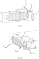
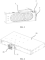
common module 1 is inserted into a cabinet, as shown inFIG. 1 , aslider 2 on a panel of themodule 1 is pressed to the left (in a direction indicated by an arrow inFIG. 1 ), anejector lever 3 is pulled out, themodule 1 is inserted into the cabinet, and then theejector lever 3 is pushed in. As shown inFIG. 2 , themodule 1 is stuck in the cabinet by using aprotrusion 4 disposed on theejector lever 3. Finally, as shown inFIG. 3 , theslider 2 is pressed to the right (in a direction indicated by an arrow inFIG. 3 ), to lock theejector lever 3 and themodule 1. When themodule 1 needs to be pulled out, theslider 2 is pressed to the left, theejector lever 3 is pulled out, and themodule 1 is pulled out. However, when this method is used, the fastener for locking themodule 1 needs to occupy space of themodule 1, and consequently an effective area of a panel is reduced. In addition, when the foregoing locking structure is used, actions such as pressing theslider 2 and pulling theejector lever 3 need to be performed, and the operations are relatively complex. - This application provides a module locking apparatus, a module, and electrical equipment, to facilitate locking of a module and reduce an area occupied by a locking apparatus on a panel of the module.
- According to a first aspect, a module locking apparatus is provided, configured to lock a module onto a cabinet. The locking apparatus includes a casing and a supporting base that serves as a supporting apparatus, where the casing covers the supporting base, and space for accommodating main moving components of the locking apparatus is formed between the supporting base and the casing. The moving components include a tongue, an elastic component, and an ejector lever, where the tongue is located between the supporting base and the casing; one end of the tongue is rotatably connected to the supporting base, and the other end of the tongue is a free end; and a hook configured to engage with the cabinet is disposed on the free end. When the module is inserted into the cabinet, the module is locked by using the hook. During hook installation, the hook needs to extend out of the casing to engage with the cabinet, and the hook is pushed by the installed elastic component to engage with the cabinet. The elastic component is configured to drive the hook to be exposed out of the casing and engage with the cabinet, so that the hook can lock the module inside the cabinet when coordinating with the cabinet. Unlocking is implemented by using the ejector lever. The ejector lever is rotatably connected to the supporting base, and can press the tongue to rotate in a direction away from the casing. When being rotated to a first specified position, the ejector lever presses the tongue to rotate to a position in which the tongue is disengaged from the cabinet, thereby implementing unlocking.
- According to the foregoing technical solution, the elastic component is used to push the hook to lock the module and the cabinet together, and to implement unlocking, only the ejector lever needs to be pulled to press the hook down. It can be learned from the foregoing description that the operations during using of the module locking apparatus provided in the present application are simple: Only the ejector lever needs to be pulled to implement unlocking, and the module is pushed into the cabinet to implement locking. In addition, when this structure is used, the tongue, the elastic component, and the ejector lever are all disposed on a side wall of the module, and only a part of the ejector lever is exposed out of a panel of the module. Compared with a module locking structure in the prior art, in this structure, an area occupied on the panel is reduced.
- A specific structure of the tongue includes a rotating shaft and a connecting plate connected to the rotating shaft. The rotating shaft is rotatably connected to the supporting base, and the hook is disposed at an end of the connecting plate away from the rotating shaft. The installed rotating shaft coordinates with the supporting base to make the tongue rotate relative to the supporting base, and the connecting plate is installed to generate a specific distance between the hook and the rotating shaft, ensuring a specific rotation distance for the hook when the tongue rotates, to lock onto and unlock from the cabinet.
- The elastic component is configured to push the tongue to rotate and enable the hook on the tongue to engage with the cabinet. The elastic component may be elastic components of different structure types. For example, the elastic component is a rotary spring. The rotary spring is sleeved on the rotating shaft of the tongue, and two ends of the rotary spring press against the supporting base and the connecting plate, respectively, to push the tongue to rotate and provide force for the hook to engage with the cabinet. Alternatively, the elastic component may be an elastic sheet. One end of the elastic sheet is provided with a bent structure, and correspondingly, a mounting base is disposed on the supporting base. The bent structure may be clamped on the mounting base, to fasten the elastic sheet onto the supporting base. The other end of the elastic sheet is a free end, and the free end presses against a surface, facing the supporting base, of the connecting plate, so that the connecting plate can be pushed to rotate in a direction away from the supporting base. Certainly, it should be understood that the elastic component may be a common elastic component different from the rotary spring and the elastic sheet, such as a compression spring or a rubber spring.
- To ensure that the ejector lever can be locked when not being used, the bent structure on the elastic sheet is connected to an elastic protrusion that coordinates with the ejector lever. When the ejector lever is rotated to a second specified position, the ejector lever disengages from the tongue, and the ejector lever engages with the elastic protrusion, so that the ejector lever is fixed. The second specified position is a position in which the ejector lever is located when the ejector lever does not push the tongue.
- A surface, facing away from the supporting base, of the connecting plate is a pressing surface that coordinates with the ejector lever, and the pressing surface is a surface pressed when the ejector lever pushes the tongue to rotate. The pressing surface faces away from the supporting base, and the pressing surface is disposed in an inclined manner opposite to a first surface, facing the supporting base, of the connecting plate. A vertical distance between the pressing surface and the first surface gradually increases in a direction away from the rotating shaft. In this way, when the ejector lever is rotated, an effect of pushing the tongue to rotate can be improved.
- The ejector lever is a C-shaped ejector lever, and two ends of the ejector lever are a first end and a second end, respectively. The first end is used for pressing the pressing surface; and when the ejector lever is rotated to the second specified position, both the first end and the second end of the ejector lever are located in a notch, and a middle part of the ejector lever is exposed outside a side face that is of the supporting base and that is perpendicular to the casing. The exposed part makes it convenient to pull the ejector lever to rotate.
- To more conveniently pull the ejector lever to rotate, an antiskid protrusion is disposed on the middle part of the ejector lever.
- During specific installation, to improve the effect of driving, by the ejector lever, the tongue to rotate, a rotation direction of the ejector lever is perpendicular to a rotation direction of the tongue.
- For ease of exposing the hook, a through hole that coordinates with the hook is disposed in the casing during installation of the casing. Pushed by the elastic component, the hook is exposed out of the through hole. When the ejector lever pushes the tongue, the hook moves back into the through hole.
- According to a second aspect, a module is provided. The module includes a module body and the locking apparatus, according to any implementation of the first aspect, fixedly connected to the module body.
- According to the foregoing technical solution, the elastic component is used to push the hook to lock the module and the cabinet together, and to implement unlocking, only the ejector lever needs to be pulled to press the hook down. It can be learned from the foregoing description that the operations during using of the module locking apparatus provided in the present application are simple: Only the ejector lever needs to be pulled to implement unlocking, and the module is pushed into the cabinet to implement locking. In addition, when this structure is used, the tongue, the elastic component, and the ejector lever are all disposed on a side wall of the module, and only a part of the ejector lever is exposed out of a panel of the module. Compared with a module locking structure in the prior art, in this structure, an area occupied on the panel is reduced.
- During specific assembly, the module further includes an outer casing covering the module body. The supporting base and the side wall of the module body are of an integrated structure, and the casing and the outer casing of the module body are of an integrated structure. In this way, the locking apparatus can be directly formed on the module body.
- According to a third aspect, electrical equipment is provided. The electrical equipment includes a cabinet and the module inserted into the cabinet, where a slot that coordinates with the hook is disposed in the cabinet.
- According to the foregoing technical solution, the elastic component is used to push the hook to lock the module and the cabinet together, and to implement unlocking, only the ejector lever needs to be pulled to press the hook down. It can be learned from the foregoing description that the operations during using of the module locking apparatus provided in the present application are simple: Only the ejector lever needs to be pulled to implement unlocking, and the module is pushed into the cabinet to implement locking. In addition, when this structure is used, the tongue, the elastic component, and the ejector lever are all disposed on a side wall of the module, and only a part of the ejector lever is exposed out of a panel of the module. Compared with a module locking structure in the prior art, in this structure, an area occupied on the panel is reduced.
-
-
FIG. 1 is a schematic diagram of inserting a module into a cabinet in the prior art; -
FIG. 2 is a schematic diagram of locking a module in a cabinet by using an ejector lever in the prior art; -
FIG. 3 is a schematic structural diagram of locking an ejector lever for a module by using a slider in the prior art; -
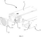
FIG. 4 is a schematic assembly diagram of a module and a cabinet according to an embodiment of this application; -
FIG. 5 is a schematic exploded view of a module according to an embodiment of this application; -
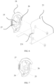
FIG. 6 is a schematic exploded view of a locking apparatus according to an embodiment of this application; -
FIG. 7 is a schematic diagram of an internal structure of a locking apparatus according to an embodiment of this application; -
FIG. 8 is a schematic exploded view of an internal structure of a locking apparatus according to an embodiment of this application; -
FIG. 9 is a schematic structural diagram of a supporting base according to an embodiment of this application; -
FIG. 10 is a schematic structural diagram of an elastic sheet according to an embodiment of this application; -
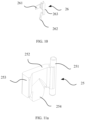
FIG. 11a is a schematic structural diagram of a tongue according to an embodiment of this application; -
FIG. 11b is a section view of a tongue according to an embodiment of this application; -
FIG. 12 is a schematic structural diagram of an ejector lever according to an embodiment of this application; -
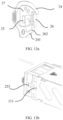
FIG. 13a to FIG. 13c are schematic diagrams of coordination between a locking apparatus and a cabinet when an ejector lever has not been rotated according to an embodiment of this application; -
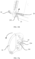
FIG. 14a andFIG. 14b are schematic diagrams of coordination between a locking apparatus and a cabinet when an ejector lever is rotated according to an embodiment of this application; and -
FIG. 15a andFIG. 15b are schematic diagrams of coordination between a locking apparatus and a cabinet when an ejector lever is rotated to a first specified position according to an embodiment of this application. - To make the objectives, technical solutions, and advantages of the present application clearer, the following further describes the present application in detail with reference to the accompanying drawings. Apparently, the described embodiments are merely some rather than all of the embodiments of the present application. Embodiments of the invention are defined by the independent claim and preferred embodiments are defined by the dependent claims.
- To facilitate understanding of a locking apparatus for a
module 20 provided in the embodiments of this application, an application scenario of the locking apparatus provided in the embodiments of this application is first described. Thelocking module 20 is applied to electrical equipment. As shown inFIG. 4 , the electrical equipment includes acabinet 10, and a plurality ofsockets 11 are disposed in thecabinet 10. Amodule 20 is inserted in eachsocket 11, and the locking apparatus provided in the embodiments of this application is configured to lockdifferent modules 20 in thecabinet 10 of the electrical equipment. The locking apparatus is disposed on themodule 20, a slot that coordinates with the locking apparatus is disposed in thecabinet 10, and themodule 20 is locked in thecabinet 10 through coordination between the locking apparatus and the slot. Themodule 20 may be acommon module 20 in the prior art, such as apower module 20, acommunication module 20, and other modules with different functions. - To resolve a prior-art problem that locking and unlocking by using a locking apparatus on a
module 20 are complex, the embodiments of this application provide the locking apparatus for themodule 20. BothFIG. 5 andFIG. 6 are referred to.FIG. 5 is a schematic assembly diagram of themodule 20 and the locking apparatus, andFIG. 6 is a schematic structural diagram of thelocking module 20. First, referring toFIG. 6 , the locking apparatus includes a supportingbase 27 and acasing 23, and the supportingbase 27 and thecasing 23 form a supporting component for supporting moving components of the locking apparatus. Also referring toFIG. 5 , when the locking apparatus is disposed on themodule 20, the supportingbase 27 and thecasing 23 of the locking apparatus may be implemented by using a side wall and an outer casing of themodule 20, respectively. In this case, the supportingbase 27 of the locking apparatus is the side wall of themodule 20, and thecasing 23 of the locking apparatus is the outer casing of themodule 20. - Still referring to
FIG. 6 , the moving components of the locking apparatus provided in the embodiments of this application include atongue 25, an elastic component, and anejector lever 24, and thetongue 25, the elastic component, and theejector lever 24 are disposed in space formed after thecasing 23 is covered on the supportingbase 27. When thetongue 25, the elastic component, and theejector lever 24 are specifically installed, refer toFIG. 7 andFIG. 8 .FIG. 7 shows a status when thetongue 25, the elastic component, and theejector lever 24 are disposed on the supportingbase 27, andFIG. 8 is a schematic exploded view when the three components are assembled with the supportingbase 27. It can be seen fromFIG. 7 that, during installation of thetongue 25, one end of thetongue 25 is rotatably connected to the supportingbase 27, and the other end is a free end. A hook is disposed on the free end, and the hook is configured to engage with a side wall of thesocket 11 in thecabinet 10 for coordination. Thetongue 25 has two working statuses when being rotated: One is that the hook is engaged with the side wall of thesocket 11 when themodule 20 is locked, and the other is that the hook is disengaged from the side wall of thesocket 11 when themodule 20 is unlocked. To engage the hook with the side wall of thesocket 11, during installation of thetongue 25, the hook on thetongue 25 extends outside thecasing 23 to engage with the side wall of thesocket 11. For ease of exposing the hook, during installation of thecasing 23, a throughhole 231 that coordinates with the hook is disposed in thecasing 23. When the hook of thetongue 25 is engaged with the side wall of thesocket 11, specific force is required to make the hook and the side wall of thesocket 11 keep in an engaged state. Therefore, the elastic component is disposed as a driving piece in the locking apparatus provided in the embodiments of this application, and the elastic component is configured to push thetongue 25 to rotate, and provide the force for making the hook on thetongue 25 engage with the side wall of thesocket 11. Theejector lever 24 in the moving components serves as an unlocking component. Theejector lever 24 is rotatably connected to the supportingbase 27, and is configured to press thetongue 25. When pressing against thetongue 25, theejector lever 24 overcomes elastic force of the elastic component and pushes thetongue 25 to rotate, to disengage the hook from the side wall of thesocket 11. During locking, theejector lever 24 is out of contact with thetongue 25, so that the elastic component can push thetongue 25 to rotate and engage with the side wall of thesocket 11. It can be learned from the foregoing description that, in the locking apparatus provided in the embodiments of this application, the elastic component is used to push the hook to lock themodule 20 and thecabinet 10 together, and to implement unlocking, only theejector lever 24 needs to be pulled to press the hook down. The operations are simple: Only theejector lever 24 needs to be pulled to implement unlocking, and themodule 20 is pushed into thecabinet 10 to implement locking. In addition, when this structure is used, as shown inFIG. 5 , thetongue 25, the elastic component, and theejector lever 24 are all disposed on the side wall of themodule 20, and only a part of theejector lever 24 is exposed out of apanel 22 of themodule 20. Compared with a locking structure for amodule 20 in the prior art, in this structure, an area occupied on thepanel 22 is reduced. - It can be learned from the foregoing description that the locking apparatus for the
module 20 provided in the embodiments of this application mainly implements locking and unlocking by using several moving components. The following describes in detail coordination between the several moving components with reference to the accompanying drawings. For ease of description, the following description is provided by using an example in which the elastic component is anelastic sheet 26. - First,
FIG. 6 is referred to.FIG. 6 is a schematic exploded view of the supportingbase 27 and thecasing 23 of thelocking module 20. It can be seen fromFIG. 6 that thecasing 23 covers the supportingbase 27, and space for accommodating the moving components may be formed between the supportingbase 27 and thecasing 23. BothFIG. 6 and FIG. 7 are referred to.FIG. 7 shows a status when the moving components are assembled on the supportingbase 27. After the moving components shown inFIG. 7 are assembled on the supportingbase 27, as shown inFIG. 6 , thecasing 23 is covered on the supportingbase 27, and is fastened onto the supportingbase 27 by using a bolt, so that the moving components are restricted inside the space between the supportingbase 27 and thecasing 23. - Both
FIG. 8 and FIG. 9 are referred to.FIG. 8 is a schematic exploded view of the moving components and the supportingbase 27.FIG. 9 is a schematic structural diagram of the supportingbase 27. In this application, the supportingbase 27 is configured to support thetongue 25, the elastic component, and theejector lever 24. To support the foregoing several moving components, a specific structure is disposed on the supportingbase 27 to coordinate with different components. As shown inFIG. 9 , afirst groove 271 for accommodating thetongue 25 and theelastic sheet 26 is disposed in the supportingbase 27. One end of thefirst groove 271 is connected to asecond groove 272 that has an arc-shaped cross section. Thesecond groove 272 is configured to coordinate with a rotating shaft of thetongue 25. When thecasing 23 is covered on the supportingbase 27, thesecond groove 272 and thecasing 23 form a spatial structure that restricts the rotating shaft of thetongue 25. In addition, a side wall of thefirst groove 271 also serves as a structure for fixing theelastic sheet 26, and aprotrusion 274 for rotatably coordinating with theejector lever 24 is further disposed on the supportingbase 27. To facilitate understanding of the foregoing structure, the following describes in detail a specific use of the foregoing structure on the supportingbase 27 with reference to several specific moving components. -
FIG. 8 toFIG. 1 are referred to.FIG. 10 is a schematic structural diagram of theelastic sheet 26. As shown inFIG. 10 , theelastic sheet 26 serves as a moving component that pushes thetongue 25 to rotate and enables the hook on thetongue 25 to engage with thecabinet 10. When being disposed in thefirst groove 271 on the supportingbase 27, as shown inFIG. 8 , theelastic sheet 26 and thetongue 25 are stacked in thefirst groove 271 in a Z direction (a direction perpendicular to a surface that is of the supportingbase 27 and on which the moving components are disposed) shown inFIG. 8 . Theelastic sheet 26 is located under thetongue 25, so that theelastic sheet 26 can push thetongue 25 towards a surface of thefirst groove 271, and further push thetongue 25 to rotate out of thefirst groove 271, to engage with a side wall of thecabinet 10. Still referring toFIG. 10 , theelastic sheet 26 is a Z-shaped structure as a whole, and one end of theelastic sheet 26 is a fixed end, and the other end thereof is a free end. The fixed end is abent structure 263 at an end of theelastic sheet 26. Thebent structure 263 is an inverted L-shapedbent structure 263, configured to be attached to the side wall of thefirst groove 271. The side wall of thefirst groove 271 is a side wall adjacent to thesecond groove 272, and serves as a mountingbase 273 to limit theelastic sheet 26. When thebent structure 263 of theelastic sheet 26 is attached onto the mountingbase 273 and thecasing 23 is covered on the supportingbase 27, the mountingbase 273 and thecasing 23 are used to clamp thebent structure 263 of theelastic sheet 26, so that theelastic sheet 26 is fixed. Still referring toFIG. 10 , it can be seen fromFIG. 10 that the free end of theelastic sheet 26 is located on a plate-like structure. The plate-like structure should be anelastic plate 261, and theelastic plate 261 is connected to the inverted L-shapedbent structure 263 such that the entireelastic sheet 26 is Z-shaped. In addition, during specific installation, theelastic plate 261 may be an arc-shaped plate or aflat plate 22. Specifically, when theelastic plate 261 is arc-shaped, an inner concave surface of theelastic plate 261 may face thetongue 25 or may face away from thetongue 25; when theelastic sheet 261 is theflat plate 22, a vertical section, relative to thebent structure 263, of theflat plate 22 is disposed in an inclined manner, so that the free end can press against thetongue 25 to push thetongue 25 to rotate outwards (outside the groove). In addition, to improve structural strength of theelastic sheet 26, thebent structure 263 and theelastic plate 261 of theelastic sheet 26 are of an integrated structure, and are made of a material having specific elasticity, such as a common material with an elastic deformation property, for example, a stainless steel plate, a copper plate, or plastics. It should be understood that theelastic sheet 26 shown inFIG. 10 is merely a specific embodiment of the elastic component provided in the embodiments of this application. The elastic component provided in the embodiments of this application may be alternatively an elastic component of a different structure type. For example, the elastic component is a rotary spring. The rotary spring is sleeved on the rotating shaft of thetongue 25, and two ends of the rotary spring press against the supportingbase 27 and a connecting plate, respectively, to push thetongue 25 to rotate and provide force for the hook to engage with thecabinet 10. Alternatively, the elastic component may be a common elastic component such as a compression spring or a rubber spring. -
FIG. 8, FIG. 9 ,FIG. 11a , andFIG. 11b are referred to.FIG. 11a andFIG. 11b show a structure and a sectional view of thetongue 25, respectively. First,FIG. 8 is referred to. It can be seen fromFIG. 8 that, during installation of thetongue 25, thetongue 25 is installed in thefirst groove 271 of the supportingbase 27. For details, refer to the foregoing description of the supportingbase 27 with reference toFIG. 9 . Thefirst groove 271 and thesecond groove 272 are disposed in the supportingbase 27 for coordination with thetongue 25. A corresponding structure of thetongue 25 is shown inFIG. 11a . Thetongue 25 includes arotating shaft 251 and a connectingplate 252 connected to therotating shaft 251. Therotating shaft 251 is configured to rotatably connect to the supportingbase 27. Ahook 253 is disposed at an end of the connectingplate 252 away from therotating shaft 251 to engage with the side wall of thecabinet 10. During specific installation, as shown inFIG. 7 andFIG. 8 , when thetongue 25 is assembled onto the supportingbase 27, therotating shaft 251 is located in thesecond groove 272, and there is a gap between therotating shaft 251 and the side wall of thefirst groove 271 to accommodate the bent structure of theelastic sheet 26. In addition, the connectingplate 252 is located in thefirst groove 271 and presses against the elastic plate of theelastic sheet 26. When thecasing 23 is covered on the supporting base, space for accommodating therotating shaft 251 is enclosed by thesecond groove 272 and thecasing 23 together, so that rotation stability of thetongue 25 can be kept when therotating shaft 251 rotates. In addition, to improve structural strength of theentire tongue 25, therotating shaft 251, the connectingplate 252, and thehook 253 are of an integrated structure, and thetongue 25 is made of a material having specific structural strength, such as stainless steel, copper, iron, or plastics. In addition, thetongue 25 may be fabricated through injection molding or stamping. - Still referring to
FIG. 11a , in addition to therotating shaft 251, the connecting plate, and thehook 253 described above, some structures for helping theejector lever 24 to drive thetongue 25 to rotate are further disposed on thetongue 25, for example, apressing surface 254 disposed on the connectingplate 252. BothFIG. 11a andFIG. 11b are referred to.FIG. 11b is a schematic diagram of a cross section that is of the connecting plate and that is perpendicular to a lengthwise direction of therotating shaft 251. Thepressing surface 254 is disposed on a surface, facing away from the supportingbase 27, of the connectingplate 252. Thepressing surface 254 is a surface pressed when theejector lever 24 pushes thetongue 25 to rotate, and thepressing surface 254 is disposed in an inclined manner opposite to afirst surface 255, facing the supportingbase 27, of the connectingplate 252. As shown inFIG. 11b , in a direction away from the rotating shaft 251 (a direction a shown inFIG. 11b ), a vertical distance between thepressing surface 254 and thefirst surface 255 gradually increases. As shown inFIG. 11b , a distance between thepressing surface 254 and a side that is of thefirst surface 255 and that is close to therotating shaft 251 is c, a distance between thepressing surface 254 and a side that is of thefirst surface 255 and that is away from therotating shaft 251 is b, and b > c. In this way, the entire connectingplate 252 becomes a structure in which the end provided with thehook 253 is relatively thick and an end connected to therotating shaft 251 is relatively thin. In this implementation, when theejector lever 24 presses thetongue 25, theejector lever 24 first presses the connectingplate 252 from the side near therotating shaft 251; and as theejector lever 24 rotates, a pressing position of theejector lever 24 on the connectingplate 252 gradually moves away from therotating shaft 251. In a process in which theejector lever 24 rotates, a thickness of a pressed section of the connectingplate 252 gradually increases. In this way, when theejector lever 24 rotates by a relatively small range, the connectingplate 252 can rotate by a relatively large range, so that a movement range of thehook 253 is increased, and thehook 253 can be quickly unlocked from the side wall of thecabinet 10. During specific installation of thepressing surface 254, thepressing surface 254 may be connected to the surface, facing away from the supportingbase 27, of the connecting plate. In this case, the cross section that is of the connecting plate and that is perpendicular to the direction of therotating shaft 251 is a triangle-like cross section. In addition, thepressing surface 254 may alternatively be some structures formed on the surface, facing away from the supportingbase 27, of the connecting plate. As shown inFIG. 11a , thepressing surface 254 is apressing surface 254 that satisfies a requirement and that is formed by forming a notch on the surface, facing away from the supportingbase 27, of the connecting plate. In addition, referring toFIG. 7 andFIG. 11a , to enable thepressing surface 254 to be closer to theejector lever 24, a protrusion is disposed on a side, facing theejector lever 24, of the connectingplate 252, and the protrusion and the connectingplate 252 are of an integrated structure. In this case, thepressing surface 254 is located on the protrusion and the connectingplate 252. - Still referring to
FIG. 11b , in the hook provided in the embodiments of this application, a cross section of the hook is a right-angled triangular structure, and during inserting themodule 20 into thesocket 11, a surface, facing thesocket 11, of the hook is an oblique surface, and a surface, facing away from thesocket 11, of the hook is a right-angled surface. In this way, when themodule 20 is pushed into thesocket 11, the side wall of thesocket 11 can press the hook to push theentire module 20 into thesocket 11. - It should be understood that
FIG. 11b shows only a specific implementation of thepressing surface 254, and another implementation may be alternatively used to improve a pressing effect generated when theejector lever 24 presses thetongue 25. If thepressing surface 254 is a surface on which a part is a spiral surface, a rotating shaft around which the spiral surface extends is the rotating shaft around which theejector lever 24 rotates. - The
ejector lever 24 provided in the embodiments of this application serves as a driving piece. When being used, theejector lever 24 presses against thetongue 25 during rotation, so that the hook on thetongue 25 can be unlocked from thecabinet 10.FIG. 8, FIG. 9 , andFIG. 12 are referred to.FIG. 12 is a schematic structural diagram of theejector lever 24 according to the embodiments of this application. In a structure shown inFIG. 12 , theejector lever 24 has two ends: afirst end 241 and asecond end 242. Thefirst end 241 is a pressing end that coordinates with thetongue 25, and thesecond end 242 is an end opposite to thefirst end 241, and serves as a force applying end. During unlocking, the force applying end is pressed, so that theejector lever 24 rotates; and when the pressing end presses against thetongue 25, thetongue 25 is driven to overcome elastic force of theelastic sheet 26 and rotate. Theejector lever 24 is a C-shapedejector lever 24, and arotating shaft hole 243 is disposed in a side that is of theejector lever 24 and that is close to thefirst end 241. With reference to the structure shown inFIG. 9 , theprotrusion 274 that coordinates with therotating shaft hole 243 is disposed on the supportingbase 27. Theprotrusion 274 serves as a rotating shaft. During assembly of theejector lever 24, theprotrusion 274 is inserted into therotating shaft hole 243; and a threaded hole is disposed in theprotrusion 274, and the threaded hole locks thecasing 23 and the supportingbase 27 together through coordination with a bolt or a screw. In addition, to reduce friction of theejector lever 24 during rotation, a bearing that can rotate relative to theprotrusion 274 is sleeved on theprotrusion 274, and the bearing is inserted into therotating shaft hole 243. - Still referring to
FIG. 9 , a notch that coordinates with the C-shapedejector lever 24 is further disposed on the supportingbase 27, and the notch is divided into two parts: a first notch and a second notch. The first notch and the second notch are arranged on two opposite sides of thefirst groove 271, and are configured to accommodate the two ends of theejector lever 24. During assembly of theejector lever 24 on the supportingbase 27, as shown inFIG. 7 , thefirst end 241 of theejector lever 24 is located in the first notch, thesecond end 242 of theejector lever 24 is located in the second notch, and a middle part of theejector lever 24 is exposed outside a side face that is of the supportingbase 27 and that is perpendicular to thecasing 23, for facilitate pulling of theejector lever 24. In addition, to more conveniently pull theejector lever 24 to rotate, anantiskid protrusion 244 is disposed on the part, exposed outside the supportingbase 27, of theejector lever 24, so that thesecond end 242 of theejector lever 24 is pulled out of the second notch. During installation of the entire locking apparatus on themodule 20, the locking apparatus is installed on the side wall of themodule 20. In this case, theejector lever 24 is exposed outside a surface of thepanel 22 of themodule 20, and only theejector lever 24 of the entire locking apparatus is exposed on thepanel 22. Therefore, compared with the prior-art structure shown inFIG. 3 , in this structure, an occupied area on thepanel 22 can be reduced, and utilization of thepanel 22 can be improved. - In addition, to ensure that the
ejector lever 24 can keep a stable posture when not pressing thetongue 25, referring to bothFIG. 10 andFIG. 12 , anelastic protrusion 262 that coordinates with thefirst end 241 of theejector lever 24 is disposed on theelastic sheet 26. Theelastic protrusion 262 is a bentelastic protrusion 262, and theelastic protrusion 262 and theelastic sheet 26 are of an integrated structure. To ensure that theejector lever 24 can be locked when not being used, when theejector lever 24 is rotated to a second specified position, theejector lever 24 engages with the elastic protrusion 262.In the second specified position, theejector lever 24 does not press thetongue 25. In this case, thesecond end 242 is located in the second notch, and thefirst end 241 presses against theelastic protrusion 262, so that theejector lever 24 can keep a stable posture. When theejector lever 24 needs to be pulled, thefirst end 241 overcomes force of theelastic protrusion 262 and rotates. - Still referring to
FIG. 6 , it can be seen from the structure shown inFIG. 6 that a rotation direction of theejector lever 24 is perpendicular to a rotation direction of thetongue 25. Theejector lever 24 is used to press thetongue 25 to change the rotation direction of theejector lever 24 to the moving direction of thetongue 25, to unlock thetongue 25 from the side wall of thecabinet 10. Certainly, during specific installation, the rotating shaft around which theejector lever 24 rotates may not be completely perpendicular to the rotating shaft around which thetongue 25 rotates, and a specific inclination angle may exist between the rotating shafts, but an application principle is the same as a principle of the structure shown inFIG. 6 in the embodiments of this application, and there is no substantial difference between the principles. - To facilitate understanding of an operating principle of the locking apparatus provided in the embodiments of this application, the following provides a detailed description with reference to the accompanying drawings. For ease of describing the principle, the locking apparatus provided in the embodiments of this application is installed on the
module 20. As shown inFIG. 5 , themodule 20 includes amodule body 21, the locking apparatus, and thepanel 22. The locking apparatus is located on the side wall of themodule body 21, and the outer casing of themodule body 21 covers the side wall of themodule body 21, thepanel 22 covers ends of themodule body 21, and correspondingly, the through hole that coordinates with theejector lever 24 is disposed in thepanel 22, so that theejector lever 24 is exposed out of thepanel 22. To ensure structure compactness, the supportingbase 27 of the locking apparatus and the side wall of themodule body 21 are of an integrated structure, and thecasing 23 of thelocking module 20 and the outer casing of themodule body 21 are of an integrated structure. - First,
FIG. 13a to FIG. 13c are referred to.FIG. 13a shows position status of the moving components of the locking structure. In these position status, the ejector lever is rotated to the second specified position, and theejector lever 24 does not press against thetongue 25. In this case, thetongue 25 is pushed by theelastic sheet 26 to press against the outer casing of themodule 20, and the hook on thetongue 25 passes through the throughhole 231 of the outer casing and then is exposed outside thecasing 23. BothFIG. 13b andFIG. 13c are referred to. First, as shown inFIG. 13b , theslot 111 that coordinates with the hook is disposed in the side wall of thesocket 11, and when themodule 20 is inserted into thesocket 11, themodule 20 is pushed in a direction indicated by a straight line with an arrow shown inFIG. 13b . Because the surface, facing thesocket 11, of the hook that is an oblique surface, the hook moves back into the throughhole 231 when being pressed by the side wall of thesocket 11; and when themodule 20 moves in place, theslot 111 in the side wall of thesocket 11 is opposite to a position of the hook. At this time, under action of theelastic sheet 26, the hook bounces and engages with theslot 111. When themodule 20 is pulled outwards, a vertical side wall of the hook presses against theslot 111, so that themodule 20 is tightly locked in thesocket 11. - Both
FIG. 14a andFIG. 14b are referred to.FIG. 14a shows a coordination status of the moving components of thelocking module 20.FIG. 14b shows a status of the correspondingmodule 20 in thesocket 11. As shown inFIG. 14a , when thesocket 11 needs to be pulled out, theejector lever 24 is rotated in a direction indicated by an arrow shown inFIG. 14a , the first end of theejector lever 24 starts to press against the pressing surface on thetongue 25 and drive thetongue 25 to rotate. As shown inFIG. 14b , the hook starts to rotate in a direction indicated by an arrow shown inFIG. 14b , to move back into the throughhole 231. - Both
FIG. 15a andFIG. 15b are referred to.FIG. 15a shows a coordination status of the moving components of thelocking module 20.FIG. 15b shows a status of the correspondingmodule 20 in thesocket 11. First, as shown inFIG. 15a , theejector lever 24 continues being rotated in a direction indicated by an arrow inFIG. 15a , so that the first end of theejector lever 24 continues pressing thetongue 25, and thetongue 25 continues rotating to a status shown inFIG. 15b . At this time, the ejector lever is rotated to the first specified position, and the hook completely moves back into the throughhole 231. - Still referring to
FIG. 5 , the embodiments of this application further provide amodule 20. Themodule 20 includes themodule body 21, the locking apparatus, and thepanel 22. The locking apparatus is located on the side wall of themodule body 21, and the outer casing of themodule body 21 covers the side wall of themodule body 21, thepanel 22 covers ends of themodule body 21, and correspondingly, the through hole that coordinates with theejector lever 24 is disposed in thepanel 22, so that theejector lever 24 is exposed out of thepanel 22. To ensure structure compactness, the supportingbase 27 of the locking apparatus and the side wall of themodule body 21 are of an integrated structure, and thecasing 23 of thelocking module 20 and the outer casing of themodule body 21 are of an integrated structure. In this embodiment, the elastic component is used to push the hook to lock themodule 20 and thecabinet 10 together, and to implement unlocking, only theejector lever 24 needs to be pulled to press the hook down. It can be learned from the foregoing description that the operations during using of the locking apparatus for themodule 20 provided in the present application are simple: Only theejector lever 24 needs to be pulled to implement unlocking, and themodule 20 is pushed into thecabinet 10 to implement locking. In addition, when this structure is used, thetongue 25, the elastic component, and theejector lever 24 are all disposed on the side wall of themodule 20, and only a part of theejector lever 24 is exposed out of thepanel 22 of themodule 20. Compared with a locking structure for amodule 20 in the prior art, in this structure, an area occupied on thepanel 22 is reduced. - Still referring to
FIG. 4 , the embodiments of this application further provide electrical equipment. The electrical equipment includes thecabinet 10 and the foregoingmodule 20 inserted into thecabinet 10. Theslot 111 that coordinates with the hook is disposed in thecabinet 10. During specific installation, thesocket 11 in one-to-one correspondence with themodule 20 is disposed in eachcabinet 10, and theslot 111 that coordinates with the hook is disposed in thesocket 11. When themodule 20 is used, the elastic component of the locking apparatus on themodule 20 is used to push the hook to lock themodule 20 and thecabinet 10 together, and to implement unlocking, only theejector lever 24 needs to be pulled to press the hook down. It can be learned from the foregoing description that the operations during using of the locking apparatus for themodule 20 provided in the present application are simple: Only theejector lever 24 needs to be pulled to implement unlocking, and themodule 20 is pushed into thecabinet 10 to implement locking. In addition, when this structure is used, thetongue 25, the elastic component, and theejector lever 24 are all disposed on the side wall of themodule 20, and only a part of theejector lever 24 is exposed out of thepanel 22 of themodule 20. Compared with a locking structure for amodule 20 in the prior art, in this structure, an area occupied on thepanel 22 is reduced. - The foregoing descriptions are merely specific implementations of the present application, but are not intended to limit the protection scope of the present application. The protection scope of the present application shall be subject to the protection scope of the claims.
Claims (13)
- A module locking apparatus, configured to be fixedly connected to the module body (21) of a module (20) and configured to lock the module (20) onto a cabinet (10), wherein the module locking apparatus comprises a supporting base (27) and a casing (23) that covers the supporting base, and further comprises an ejector lever (24), a tongue (25), and an elastic component (26), whereinthe tongue is located between the supporting base and the casing; one end of the tongue is rotatably connected to the supporting base, and the other end of the tongue is a free end; and a hook (253) configured to engage with the cabinet is disposed on the free end and the tongue (25) has two working statuses when being rotated: one is that the hook is engaged with the cabinet when the module (20) is locked, and the other is that the hook is disengaged from the cabinet when the module (20) is unlocked;the elastic component (26) is disposed as a driving piece in the locking apparatus and is configured to drive the hook to be exposed out of the casing and engage with the cabinet; andthe ejector lever (24) serves as an unlocking component and is rotatably connected to the supporting base and is configured to press the tongue;during locking the ejector lever is out of contact with the tongue, so that the elastic component can push the tongue to rotate and engage with the cabinet, and when being rotated to a first specified position, the ejector lever presses the tongue to rotate to a position in which the tongue is disengaged from the cabinet.
- The module locking apparatus according to claim 1, wherein the tongue comprises a rotating shaft rotatably connected to the supporting base and a connecting plate (252) connected to the rotating shaft, wherein the hook is disposed at an end of the connecting plate away from the rotating shaft.
- The module locking apparatus according to claim 2, wherein the elastic component is a rotary spring, the rotary spring is sleeved on the rotating shaft, and two ends of the rotary spring press against the supporting base and the connecting plate, respectively.
- The module locking apparatus according to claim 2, whereina mounting base is disposed on the supporting base; andthe elastic component is an elastic sheet; one end of the elastic sheet is provided with a bent structure clamped on the mounting base, and the other end of the elastic sheet is a free end; and the free end of the elastic sheet presses against a surface, facing the supporting base, of the connecting plate.
- The module locking apparatus according to claim 4, wherein the bent structure is connected to an elastic protrusion that coordinates with the ejector lever; and
when the ejector lever is rotated to a second specified position, the ejector lever disengages from the tongue, and the ejector lever engages with the elastic protrusion. - The module locking apparatus according to any one of claims 2 to 5, wherein a surface, facing away from the supporting base, of the connecting plate is a pressing surface that coordinates with the ejector lever; the pressing surface is disposed in an inclined manner opposite to a first surface, facing the supporting base, of the connecting plate; and a vertical distance between the pressing surface and the first surface gradually increases in a direction away from the rotating shaft.
- The module locking apparatus according to claim 6, wherein the ejector lever is a C-shaped ejector lever, and two ends of the ejector lever are a first end and a second end, respectively, wherein the first end is used for pressing the pressing surface; and
a notch for accommodating the first end and the second end is disposed on the supporting base, and when the ejector lever is rotated to the second specified position, both the first end and the second end of the ejector lever are located in the notch, and a middle part of the ejector lever is exposed outside a side face that is of the supporting base and that is perpendicular to the casing. - The module locking apparatus according to claim 7, wherein an antiskid protrusion is disposed on the middle part of the ejector lever.
- The module locking apparatus according to claim 1, wherein a rotation direction of the ejector lever is perpendicular to a rotation direction of the tongue.
- The module locking apparatus according to claim 1, wherein a through hole that coordinates with the hook is disposed in the casing.
- A module, comprising a module body (21) and the locking apparatus, according to any one of claims 1 to 10, fixedly connected to the module body.
- The module according to claim 11, further comprising an outer casing covering the module body, wherein the supporting base and a side wall of the module body are of an integrated structure, and the casing and the outer casing of the module body are of an integrated structure.
- Electrical equipment, comprising a cabinet and the module, according to claim 11 or 12, inserted into the cabinet, wherein a slot that coordinates with the hook is disposed in the cabinet.
Applications Claiming Priority (1)
| Application Number | Priority Date | Filing Date | Title |
|---|---|---|---|
| CN201810609961.0A CN108770277B (en) | 2018-06-13 | 2018-06-13 | Locking device of module, module and electrical equipment |
Publications (2)
| Publication Number | Publication Date |
|---|---|
| EP3582594A1 EP3582594A1 (en) | 2019-12-18 |
| EP3582594B1 true EP3582594B1 (en) | 2023-11-22 |
Family
ID=64021686
Family Applications (1)
| Application Number | Title | Priority Date | Filing Date |
|---|---|---|---|
| EP19180021.8A Active EP3582594B1 (en) | 2018-06-13 | 2019-06-13 | Module locking apparatus, module, and electrical equipment |
Country Status (2)
| Country | Link |
|---|---|
| EP (1) | EP3582594B1 (en) |
| CN (1) | CN108770277B (en) |
Families Citing this family (2)
| Publication number | Priority date | Publication date | Assignee | Title |
|---|---|---|---|---|
| CN113175272B (en) * | 2020-01-25 | 2025-01-21 | 广东金点原子安防科技股份有限公司 | A modular electromechanical lock body |
| CN117239608B (en) * | 2023-11-16 | 2024-06-28 | 西安图为电气技术有限公司 | Electrical equipment cabinet and power module thereof |
Family Cites Families (16)
| Publication number | Priority date | Publication date | Assignee | Title |
|---|---|---|---|---|
| KR960032380U (en) * | 1995-03-10 | 1996-10-24 | Fastening device of computer case | |
| CN101871293B (en) * | 2009-04-24 | 2012-01-11 | 辽宁聚龙金融设备股份有限公司 | Movable paper money storage box |
| DE102010035101A1 (en) * | 2010-08-23 | 2012-02-23 | Rohde & Schwarz Gmbh & Co. Kg | Locking system for assemblies on the housing and assembly process |
| TW201228566A (en) * | 2010-12-24 | 2012-07-01 | Hon Hai Prec Ind Co Ltd | Anti-drop mechanism |
| CN102573379A (en) * | 2010-12-25 | 2012-07-11 | 鸿富锦精密工业(深圳)有限公司 | Electronic device |
| TWI441013B (en) * | 2011-10-18 | 2014-06-11 | Hon Hai Prec Ind Co Ltd | Power supply unit |
| TWM425502U (en) * | 2011-10-31 | 2012-03-21 | Hon Hai Prec Ind Co Ltd | Removable electronic device |
| CN102573375B (en) * | 2012-01-05 | 2015-01-07 | 华为技术有限公司 | Module with wrench and module component |
| CN104345774B (en) * | 2013-07-29 | 2017-09-22 | 英业达科技有限公司 | Server and its bearing structure |
| EP3271533B1 (en) * | 2015-03-16 | 2020-08-26 | Vander Industries Pty. Ltd. | Push and/or pull handle lockset |
| CN106941767A (en) * | 2016-01-04 | 2017-07-11 | 中兴通讯股份有限公司 | A kind of communication equipment of push-pull structure and the application push-pull structure |
| US10356955B2 (en) * | 2016-05-11 | 2019-07-16 | Facebook, Inc. | Modular network switches, associated structures, and associated methods of manufacture and use |
| CN206603480U (en) * | 2016-08-04 | 2017-11-03 | 胡旭阳 | A kind of adjustable disassembly and assembly structure of drawer sliding rail |
| CN106292925A (en) * | 2016-08-23 | 2017-01-04 | 浪潮电子信息产业股份有限公司 | Handles available for tray fixing in server products |
| CN207374881U (en) * | 2017-07-03 | 2018-05-18 | 台州市腾强塑业有限公司 | Portable storage box |
| CN207135395U (en) * | 2017-09-18 | 2018-03-23 | 丁勇杰 | Airborne emergency communication equipment |
-
2018
- 2018-06-13 CN CN201810609961.0A patent/CN108770277B/en active Active
-
2019
- 2019-06-13 EP EP19180021.8A patent/EP3582594B1/en active Active
Also Published As
| Publication number | Publication date |
|---|---|
| EP3582594A1 (en) | 2019-12-18 |
| CN108770277A (en) | 2018-11-06 |
| CN108770277B (en) | 2020-08-25 |
Similar Documents
| Publication | Publication Date | Title |
|---|---|---|
| US7855881B2 (en) | Mounting apparatus for back panel | |
| US7483267B2 (en) | Mounting apparatus for securing storage device | |
| US8411429B2 (en) | Mounting apparatus for disk drive | |
| US8498104B2 (en) | Mounting apparatus for data storage device | |
| US20120020037A1 (en) | Expansion card mounting assembly | |
| US8154863B2 (en) | Data storage device assembly | |
| US8605440B2 (en) | Server rack assembly | |
| CN113050759B (en) | Handle device, chassis and server | |
| US20100124015A1 (en) | Computer enclosure with power supply | |
| CN102171525A (en) | Control cabinet arrangement | |
| EP3582594A1 (en) | Module locking apparatus, module, and electrical equipment | |
| US20180007804A1 (en) | Fixing apparatus and electronic equipment using the same | |
| US8240627B2 (en) | Retaining assembly for locking disk drive | |
| US9210821B2 (en) | Locking assembly and communication apparatus using same | |
| US7232193B2 (en) | Locking mechanism for securing the bezel of an electronics enclosure to a rack structure | |
| US8564962B2 (en) | Electronic device with detachable power module | |
| US6123579A (en) | Electrical connector mounting arrangement | |
| CN217506469U (en) | Hard disk fixing device and case | |
| CN205281367U (en) | Fixing device for expansion card | |
| US8545249B2 (en) | Locking assembly and communication apparatus using same | |
| CN113685092B (en) | Locking structure and server case with same | |
| CN218940209U (en) | Self-locking mechanism, pull-out assisting device assembly and communication device | |
| US5967825A (en) | Integral actuator for a printed circuit board | |
| US8233285B2 (en) | Linecard to chassis securing | |
| CN220014763U (en) | Handle, dummy panel and communication device |
Legal Events
| Date | Code | Title | Description |
|---|---|---|---|
| PUAI | Public reference made under article 153(3) epc to a published international application that has entered the european phase |
Free format text: ORIGINAL CODE: 0009012 |
|
| STAA | Information on the status of an ep patent application or granted ep patent |
Free format text: STATUS: REQUEST FOR EXAMINATION WAS MADE |
|
| 17P | Request for examination filed |
Effective date: 20190613 |
|
| AK | Designated contracting states |
Kind code of ref document: A1 Designated state(s): AL AT BE BG CH CY CZ DE DK EE ES FI FR GB GR HR HU IE IS IT LI LT LU LV MC MK MT NL NO PL PT RO RS SE SI SK SM TR |
|
| AX | Request for extension of the european patent |
Extension state: BA ME |
|
| RAP1 | Party data changed (applicant data changed or rights of an application transferred) |
Owner name: HUAWEI DIGITAL POWER TECHNOLOGIES CO., LTD. |
|
| STAA | Information on the status of an ep patent application or granted ep patent |
Free format text: STATUS: EXAMINATION IS IN PROGRESS |
|
| 17Q | First examination report despatched |
Effective date: 20211222 |
|
| GRAP | Despatch of communication of intention to grant a patent |
Free format text: ORIGINAL CODE: EPIDOSNIGR1 |
|
| STAA | Information on the status of an ep patent application or granted ep patent |
Free format text: STATUS: GRANT OF PATENT IS INTENDED |
|
| INTG | Intention to grant announced |
Effective date: 20230616 |
|
| GRAS | Grant fee paid |
Free format text: ORIGINAL CODE: EPIDOSNIGR3 |
|
| GRAA | (expected) grant |
Free format text: ORIGINAL CODE: 0009210 |
|
| STAA | Information on the status of an ep patent application or granted ep patent |
Free format text: STATUS: THE PATENT HAS BEEN GRANTED |
|
| AK | Designated contracting states |
Kind code of ref document: B1 Designated state(s): AL AT BE BG CH CY CZ DE DK EE ES FI FR GB GR HR HU IE IS IT LI LT LU LV MC MK MT NL NO PL PT RO RS SE SI SK SM TR |
|
| REG | Reference to a national code |
Ref country code: GB Ref legal event code: FG4D |
|
| REG | Reference to a national code |
Ref country code: CH Ref legal event code: EP |
|
| REG | Reference to a national code |
Ref country code: DE Ref legal event code: R096 Ref document number: 602019041779 Country of ref document: DE |
|
| REG | Reference to a national code |
Ref country code: IE Ref legal event code: FG4D |
|
| P01 | Opt-out of the competence of the unified patent court (upc) registered |
Effective date: 20231121 |
|
| REG | Reference to a national code |
Ref country code: LT Ref legal event code: MG9D |
|
| REG | Reference to a national code |
Ref country code: NL Ref legal event code: MP Effective date: 20231122 |
|
| PG25 | Lapsed in a contracting state [announced via postgrant information from national office to epo] |
Ref country code: GR Free format text: LAPSE BECAUSE OF FAILURE TO SUBMIT A TRANSLATION OF THE DESCRIPTION OR TO PAY THE FEE WITHIN THE PRESCRIBED TIME-LIMIT Effective date: 20240223 |
|
| PG25 | Lapsed in a contracting state [announced via postgrant information from national office to epo] |
Ref country code: IS Free format text: LAPSE BECAUSE OF FAILURE TO SUBMIT A TRANSLATION OF THE DESCRIPTION OR TO PAY THE FEE WITHIN THE PRESCRIBED TIME-LIMIT Effective date: 20240322 |
|
| PG25 | Lapsed in a contracting state [announced via postgrant information from national office to epo] |
Ref country code: LT Free format text: LAPSE BECAUSE OF FAILURE TO SUBMIT A TRANSLATION OF THE DESCRIPTION OR TO PAY THE FEE WITHIN THE PRESCRIBED TIME-LIMIT Effective date: 20231122 |
|
| REG | Reference to a national code |
Ref country code: AT Ref legal event code: MK05 Ref document number: 1635085 Country of ref document: AT Kind code of ref document: T Effective date: 20231122 |
|
| PG25 | Lapsed in a contracting state [announced via postgrant information from national office to epo] |
Ref country code: NL Free format text: LAPSE BECAUSE OF FAILURE TO SUBMIT A TRANSLATION OF THE DESCRIPTION OR TO PAY THE FEE WITHIN THE PRESCRIBED TIME-LIMIT Effective date: 20231122 |
|
| PG25 | Lapsed in a contracting state [announced via postgrant information from national office to epo] |
Ref country code: AT Free format text: LAPSE BECAUSE OF FAILURE TO SUBMIT A TRANSLATION OF THE DESCRIPTION OR TO PAY THE FEE WITHIN THE PRESCRIBED TIME-LIMIT Effective date: 20231122 |
|
| PG25 | Lapsed in a contracting state [announced via postgrant information from national office to epo] |
Ref country code: ES Free format text: LAPSE BECAUSE OF FAILURE TO SUBMIT A TRANSLATION OF THE DESCRIPTION OR TO PAY THE FEE WITHIN THE PRESCRIBED TIME-LIMIT Effective date: 20231122 |
|
| PG25 | Lapsed in a contracting state [announced via postgrant information from national office to epo] |
Ref country code: NL Free format text: LAPSE BECAUSE OF FAILURE TO SUBMIT A TRANSLATION OF THE DESCRIPTION OR TO PAY THE FEE WITHIN THE PRESCRIBED TIME-LIMIT Effective date: 20231122 Ref country code: LT Free format text: LAPSE BECAUSE OF FAILURE TO SUBMIT A TRANSLATION OF THE DESCRIPTION OR TO PAY THE FEE WITHIN THE PRESCRIBED TIME-LIMIT Effective date: 20231122 Ref country code: IS Free format text: LAPSE BECAUSE OF FAILURE TO SUBMIT A TRANSLATION OF THE DESCRIPTION OR TO PAY THE FEE WITHIN THE PRESCRIBED TIME-LIMIT Effective date: 20240322 Ref country code: GR Free format text: LAPSE BECAUSE OF FAILURE TO SUBMIT A TRANSLATION OF THE DESCRIPTION OR TO PAY THE FEE WITHIN THE PRESCRIBED TIME-LIMIT Effective date: 20240223 Ref country code: ES Free format text: LAPSE BECAUSE OF FAILURE TO SUBMIT A TRANSLATION OF THE DESCRIPTION OR TO PAY THE FEE WITHIN THE PRESCRIBED TIME-LIMIT Effective date: 20231122 Ref country code: BG Free format text: LAPSE BECAUSE OF FAILURE TO SUBMIT A TRANSLATION OF THE DESCRIPTION OR TO PAY THE FEE WITHIN THE PRESCRIBED TIME-LIMIT Effective date: 20240222 Ref country code: AT Free format text: LAPSE BECAUSE OF FAILURE TO SUBMIT A TRANSLATION OF THE DESCRIPTION OR TO PAY THE FEE WITHIN THE PRESCRIBED TIME-LIMIT Effective date: 20231122 Ref country code: PT Free format text: LAPSE BECAUSE OF FAILURE TO SUBMIT A TRANSLATION OF THE DESCRIPTION OR TO PAY THE FEE WITHIN THE PRESCRIBED TIME-LIMIT Effective date: 20240322 |
|
| PG25 | Lapsed in a contracting state [announced via postgrant information from national office to epo] |
Ref country code: SE Free format text: LAPSE BECAUSE OF FAILURE TO SUBMIT A TRANSLATION OF THE DESCRIPTION OR TO PAY THE FEE WITHIN THE PRESCRIBED TIME-LIMIT Effective date: 20231122 Ref country code: RS Free format text: LAPSE BECAUSE OF FAILURE TO SUBMIT A TRANSLATION OF THE DESCRIPTION OR TO PAY THE FEE WITHIN THE PRESCRIBED TIME-LIMIT Effective date: 20231122 Ref country code: PL Free format text: LAPSE BECAUSE OF FAILURE TO SUBMIT A TRANSLATION OF THE DESCRIPTION OR TO PAY THE FEE WITHIN THE PRESCRIBED TIME-LIMIT Effective date: 20231122 Ref country code: NO Free format text: LAPSE BECAUSE OF FAILURE TO SUBMIT A TRANSLATION OF THE DESCRIPTION OR TO PAY THE FEE WITHIN THE PRESCRIBED TIME-LIMIT Effective date: 20240222 Ref country code: LV Free format text: LAPSE BECAUSE OF FAILURE TO SUBMIT A TRANSLATION OF THE DESCRIPTION OR TO PAY THE FEE WITHIN THE PRESCRIBED TIME-LIMIT Effective date: 20231122 Ref country code: HR Free format text: LAPSE BECAUSE OF FAILURE TO SUBMIT A TRANSLATION OF THE DESCRIPTION OR TO PAY THE FEE WITHIN THE PRESCRIBED TIME-LIMIT Effective date: 20231122 |
|
| PG25 | Lapsed in a contracting state [announced via postgrant information from national office to epo] |
Ref country code: DK Free format text: LAPSE BECAUSE OF FAILURE TO SUBMIT A TRANSLATION OF THE DESCRIPTION OR TO PAY THE FEE WITHIN THE PRESCRIBED TIME-LIMIT Effective date: 20231122 |
|
| PG25 | Lapsed in a contracting state [announced via postgrant information from national office to epo] |
Ref country code: CZ Free format text: LAPSE BECAUSE OF FAILURE TO SUBMIT A TRANSLATION OF THE DESCRIPTION OR TO PAY THE FEE WITHIN THE PRESCRIBED TIME-LIMIT Effective date: 20231122 |
|
| PG25 | Lapsed in a contracting state [announced via postgrant information from national office to epo] |
Ref country code: SK Free format text: LAPSE BECAUSE OF FAILURE TO SUBMIT A TRANSLATION OF THE DESCRIPTION OR TO PAY THE FEE WITHIN THE PRESCRIBED TIME-LIMIT Effective date: 20231122 |
|
| PG25 | Lapsed in a contracting state [announced via postgrant information from national office to epo] |
Ref country code: SM Free format text: LAPSE BECAUSE OF FAILURE TO SUBMIT A TRANSLATION OF THE DESCRIPTION OR TO PAY THE FEE WITHIN THE PRESCRIBED TIME-LIMIT Effective date: 20231122 Ref country code: SK Free format text: LAPSE BECAUSE OF FAILURE TO SUBMIT A TRANSLATION OF THE DESCRIPTION OR TO PAY THE FEE WITHIN THE PRESCRIBED TIME-LIMIT Effective date: 20231122 Ref country code: RO Free format text: LAPSE BECAUSE OF FAILURE TO SUBMIT A TRANSLATION OF THE DESCRIPTION OR TO PAY THE FEE WITHIN THE PRESCRIBED TIME-LIMIT Effective date: 20231122 Ref country code: IT Free format text: LAPSE BECAUSE OF FAILURE TO SUBMIT A TRANSLATION OF THE DESCRIPTION OR TO PAY THE FEE WITHIN THE PRESCRIBED TIME-LIMIT Effective date: 20231122 Ref country code: EE Free format text: LAPSE BECAUSE OF FAILURE TO SUBMIT A TRANSLATION OF THE DESCRIPTION OR TO PAY THE FEE WITHIN THE PRESCRIBED TIME-LIMIT Effective date: 20231122 Ref country code: DK Free format text: LAPSE BECAUSE OF FAILURE TO SUBMIT A TRANSLATION OF THE DESCRIPTION OR TO PAY THE FEE WITHIN THE PRESCRIBED TIME-LIMIT Effective date: 20231122 Ref country code: CZ Free format text: LAPSE BECAUSE OF FAILURE TO SUBMIT A TRANSLATION OF THE DESCRIPTION OR TO PAY THE FEE WITHIN THE PRESCRIBED TIME-LIMIT Effective date: 20231122 |
|
| REG | Reference to a national code |
Ref country code: DE Ref legal event code: R097 Ref document number: 602019041779 Country of ref document: DE |
|
| PLBE | No opposition filed within time limit |
Free format text: ORIGINAL CODE: 0009261 |
|
| STAA | Information on the status of an ep patent application or granted ep patent |
Free format text: STATUS: NO OPPOSITION FILED WITHIN TIME LIMIT |
|
| PG25 | Lapsed in a contracting state [announced via postgrant information from national office to epo] |
Ref country code: SI Free format text: LAPSE BECAUSE OF FAILURE TO SUBMIT A TRANSLATION OF THE DESCRIPTION OR TO PAY THE FEE WITHIN THE PRESCRIBED TIME-LIMIT Effective date: 20231122 |
|
| 26N | No opposition filed |
Effective date: 20240823 |
|
| PG25 | Lapsed in a contracting state [announced via postgrant information from national office to epo] |
Ref country code: SI Free format text: LAPSE BECAUSE OF FAILURE TO SUBMIT A TRANSLATION OF THE DESCRIPTION OR TO PAY THE FEE WITHIN THE PRESCRIBED TIME-LIMIT Effective date: 20231122 |
|
| PG25 | Lapsed in a contracting state [announced via postgrant information from national office to epo] |
Ref country code: MC Free format text: LAPSE BECAUSE OF FAILURE TO SUBMIT A TRANSLATION OF THE DESCRIPTION OR TO PAY THE FEE WITHIN THE PRESCRIBED TIME-LIMIT Effective date: 20231122 |
|
| REG | Reference to a national code |
Ref country code: CH Ref legal event code: PL |
|
| PG25 | Lapsed in a contracting state [announced via postgrant information from national office to epo] |
Ref country code: LU Free format text: LAPSE BECAUSE OF NON-PAYMENT OF DUE FEES Effective date: 20240613 |
|
| GBPC | Gb: european patent ceased through non-payment of renewal fee |
Effective date: 20240613 |
|
| PG25 | Lapsed in a contracting state [announced via postgrant information from national office to epo] |
Ref country code: IE Free format text: LAPSE BECAUSE OF NON-PAYMENT OF DUE FEES Effective date: 20240613 |
|
| PG25 | Lapsed in a contracting state [announced via postgrant information from national office to epo] |
Ref country code: CH Free format text: LAPSE BECAUSE OF NON-PAYMENT OF DUE FEES Effective date: 20240630 Ref country code: BE Free format text: LAPSE BECAUSE OF NON-PAYMENT OF DUE FEES Effective date: 20240630 |
|
| PG25 | Lapsed in a contracting state [announced via postgrant information from national office to epo] |
Ref country code: FR Free format text: LAPSE BECAUSE OF NON-PAYMENT OF DUE FEES Effective date: 20240630 |
|
| PG25 | Lapsed in a contracting state [announced via postgrant information from national office to epo] |
Ref country code: GB Free format text: LAPSE BECAUSE OF NON-PAYMENT OF DUE FEES Effective date: 20240613 |
|
| REG | Reference to a national code |
Ref country code: BE Ref legal event code: MM Effective date: 20240630 |
|
| PG25 | Lapsed in a contracting state [announced via postgrant information from national office to epo] |
Ref country code: FI Free format text: LAPSE BECAUSE OF FAILURE TO SUBMIT A TRANSLATION OF THE DESCRIPTION OR TO PAY THE FEE WITHIN THE PRESCRIBED TIME-LIMIT Effective date: 20231122 |
|
| PG25 | Lapsed in a contracting state [announced via postgrant information from national office to epo] |
Ref country code: CY Free format text: LAPSE BECAUSE OF FAILURE TO SUBMIT A TRANSLATION OF THE DESCRIPTION OR TO PAY THE FEE WITHIN THE PRESCRIBED TIME-LIMIT; INVALID AB INITIO Effective date: 20190613 |
|
| PG25 | Lapsed in a contracting state [announced via postgrant information from national office to epo] |
Ref country code: HU Free format text: LAPSE BECAUSE OF FAILURE TO SUBMIT A TRANSLATION OF THE DESCRIPTION OR TO PAY THE FEE WITHIN THE PRESCRIBED TIME-LIMIT; INVALID AB INITIO Effective date: 20190613 |
|
| PG25 | Lapsed in a contracting state [announced via postgrant information from national office to epo] |
Ref country code: TR Free format text: LAPSE BECAUSE OF FAILURE TO SUBMIT A TRANSLATION OF THE DESCRIPTION OR TO PAY THE FEE WITHIN THE PRESCRIBED TIME-LIMIT Effective date: 20231122 |
|
| PGFP | Annual fee paid to national office [announced via postgrant information from national office to epo] |
Ref country code: DE Payment date: 20260506 Year of fee payment: 8 |