EP3582453A1 - Management system, management device, and management method and program - Google Patents
Management system, management device, and management method and program Download PDFInfo
- Publication number
- EP3582453A1 EP3582453A1 EP18748519.8A EP18748519A EP3582453A1 EP 3582453 A1 EP3582453 A1 EP 3582453A1 EP 18748519 A EP18748519 A EP 18748519A EP 3582453 A1 EP3582453 A1 EP 3582453A1
- Authority
- EP
- European Patent Office
- Prior art keywords
- management node
- management
- congestion
- processing
- node
- Prior art date
- Legal status (The legal status is an assumption and is not a legal conclusion. Google has not performed a legal analysis and makes no representation as to the accuracy of the status listed.)
- Granted
Links
Images






Classifications
-
- H—ELECTRICITY
- H04—ELECTRIC COMMUNICATION TECHNIQUE
- H04L—TRANSMISSION OF DIGITAL INFORMATION, e.g. TELEGRAPHIC COMMUNICATION
- H04L43/00—Arrangements for monitoring or testing data switching networks
- H04L43/08—Monitoring or testing based on specific metrics, e.g. QoS, energy consumption or environmental parameters
- H04L43/0876—Network utilisation, e.g. volume of load or congestion level
-
- G—PHYSICS
- G06—COMPUTING OR CALCULATING; COUNTING
- G06F—ELECTRIC DIGITAL DATA PROCESSING
- G06F9/00—Arrangements for program control, e.g. control units
- G06F9/06—Arrangements for program control, e.g. control units using stored programs, i.e. using an internal store of processing equipment to receive or retain programs
- G06F9/44—Arrangements for executing specific programs
- G06F9/455—Emulation; Interpretation; Software simulation, e.g. virtualisation or emulation of application or operating system execution engines
- G06F9/45533—Hypervisors; Virtual machine monitors
- G06F9/45558—Hypervisor-specific management and integration aspects
-
- G—PHYSICS
- G06—COMPUTING OR CALCULATING; COUNTING
- G06F—ELECTRIC DIGITAL DATA PROCESSING
- G06F17/00—Digital computing or data processing equipment or methods, specially adapted for specific functions
- G06F17/10—Complex mathematical operations
- G06F17/18—Complex mathematical operations for evaluating statistical data, e.g. average values, frequency distributions, probability functions, regression analysis
-
- H—ELECTRICITY
- H04—ELECTRIC COMMUNICATION TECHNIQUE
- H04L—TRANSMISSION OF DIGITAL INFORMATION, e.g. TELEGRAPHIC COMMUNICATION
- H04L41/00—Arrangements for maintenance, administration or management of data switching networks, e.g. of packet switching networks
- H04L41/08—Configuration management of networks or network elements
- H04L41/0803—Configuration setting
- H04L41/0813—Configuration setting characterised by the conditions triggering a change of settings
- H04L41/0816—Configuration setting characterised by the conditions triggering a change of settings the condition being an adaptation, e.g. in response to network events
-
- H—ELECTRICITY
- H04—ELECTRIC COMMUNICATION TECHNIQUE
- H04L—TRANSMISSION OF DIGITAL INFORMATION, e.g. TELEGRAPHIC COMMUNICATION
- H04L41/00—Arrangements for maintenance, administration or management of data switching networks, e.g. of packet switching networks
- H04L41/08—Configuration management of networks or network elements
- H04L41/0895—Configuration of virtualised networks or elements, e.g. virtualised network function or OpenFlow elements
-
- H—ELECTRICITY
- H04—ELECTRIC COMMUNICATION TECHNIQUE
- H04L—TRANSMISSION OF DIGITAL INFORMATION, e.g. TELEGRAPHIC COMMUNICATION
- H04L41/00—Arrangements for maintenance, administration or management of data switching networks, e.g. of packet switching networks
- H04L41/40—Arrangements for maintenance, administration or management of data switching networks, e.g. of packet switching networks using virtualisation of network functions or resources, e.g. SDN or NFV entities
-
- H—ELECTRICITY
- H04—ELECTRIC COMMUNICATION TECHNIQUE
- H04L—TRANSMISSION OF DIGITAL INFORMATION, e.g. TELEGRAPHIC COMMUNICATION
- H04L43/00—Arrangements for monitoring or testing data switching networks
- H04L43/20—Arrangements for monitoring or testing data switching networks the monitoring system or the monitored elements being virtualised, abstracted or software-defined entities, e.g. SDN or NFV
-
- G—PHYSICS
- G06—COMPUTING OR CALCULATING; COUNTING
- G06F—ELECTRIC DIGITAL DATA PROCESSING
- G06F9/00—Arrangements for program control, e.g. control units
- G06F9/06—Arrangements for program control, e.g. control units using stored programs, i.e. using an internal store of processing equipment to receive or retain programs
- G06F9/44—Arrangements for executing specific programs
- G06F9/455—Emulation; Interpretation; Software simulation, e.g. virtualisation or emulation of application or operating system execution engines
- G06F9/45533—Hypervisors; Virtual machine monitors
- G06F9/45558—Hypervisor-specific management and integration aspects
- G06F2009/45562—Creating, deleting, cloning virtual machine instances
-
- G—PHYSICS
- G06—COMPUTING OR CALCULATING; COUNTING
- G06F—ELECTRIC DIGITAL DATA PROCESSING
- G06F9/00—Arrangements for program control, e.g. control units
- G06F9/06—Arrangements for program control, e.g. control units using stored programs, i.e. using an internal store of processing equipment to receive or retain programs
- G06F9/44—Arrangements for executing specific programs
- G06F9/455—Emulation; Interpretation; Software simulation, e.g. virtualisation or emulation of application or operating system execution engines
- G06F9/45533—Hypervisors; Virtual machine monitors
- G06F9/45558—Hypervisor-specific management and integration aspects
- G06F2009/45575—Starting, stopping, suspending or resuming virtual machine instances
-
- G—PHYSICS
- G06—COMPUTING OR CALCULATING; COUNTING
- G06F—ELECTRIC DIGITAL DATA PROCESSING
- G06F9/00—Arrangements for program control, e.g. control units
- G06F9/06—Arrangements for program control, e.g. control units using stored programs, i.e. using an internal store of processing equipment to receive or retain programs
- G06F9/44—Arrangements for executing specific programs
- G06F9/455—Emulation; Interpretation; Software simulation, e.g. virtualisation or emulation of application or operating system execution engines
- G06F9/45533—Hypervisors; Virtual machine monitors
- G06F9/45558—Hypervisor-specific management and integration aspects
- G06F2009/45587—Isolation or security of virtual machine instances
-
- G—PHYSICS
- G06—COMPUTING OR CALCULATING; COUNTING
- G06F—ELECTRIC DIGITAL DATA PROCESSING
- G06F9/00—Arrangements for program control, e.g. control units
- G06F9/06—Arrangements for program control, e.g. control units using stored programs, i.e. using an internal store of processing equipment to receive or retain programs
- G06F9/44—Arrangements for executing specific programs
- G06F9/455—Emulation; Interpretation; Software simulation, e.g. virtualisation or emulation of application or operating system execution engines
- G06F9/45533—Hypervisors; Virtual machine monitors
- G06F9/45558—Hypervisor-specific management and integration aspects
- G06F2009/45595—Network integration; Enabling network access in virtual machine instances
Definitions
- the present invention relates to a management system, a management apparatus, a management method, and a program.
- NFV network function virtualisation
- Non-Patent Literature 1 discloses a configuration for implementing NFV.
- a network functions virtualisation orchestrator (NFVO), a virtualised network functions manager (VNFM), and a virtualised infrastructure manager (VIM) perform virtual resource management, virtualised network functions (VNF) lifecycle management, and the like.
- the NFVO and the VNFM request the VIM to perform virtual resource management and/or VNF lifecycle management.
- the VIM then performs the virtual resource management and/or the VNF lifecycle management.
- Patent Literature 1 describes a technique for performing VNF scale out in NFV environment.
- the VNFM includes a VNFM surplus resource information database (DB) to store surplus resource information of surplus resources, which are surplus virtual resources reserved in a VIM in advance.
- the VNFM identifies a virtual server with the reserved surplus resources, based on the surplus resource information stored in the VNFM surplus resource information DB, and transmits an instruction to provide the identified virtual server to the VIM.
- the VIM Upon receipt of the instruction to provide the virtual server from the VNFM, the VIM provides the virtual server.
- DB VNFM surplus resource information database
- Patent Literature 2 describes a technique for performing, even when switching of a plurality of virtual machines or the like has been performed by various control apparatuses, control for acquiring the latest data from a database.
- an NFVO stores delay information indicating synchronization delay between storages.
- a VNF accepts a transmission request from a mobile communication terminal. In response to the accepted transmission request, the VNF further accesses at least one database apparatus among a plurality of database apparatuses. The VNF further acquires the delay information from the NFVO and also receives a switching request. The VNF is triggered by the acceptance of the switching request to control for acquiring the latest data from the database apparatus, based on the delay information.
- Non-Patent Literature 1 " Network Functions Orchestration (NFV); Management and Orchestration; Functional requirements specification", ETSI GS NFV-IFA 010 V2.1.1 (2016-04), [online] searched on December 28, 2016, the Internet ⁇ URL: http://www.etsi.org/deliver/etsi_gs/NFV-IFA/001_099/010/02.01.01_60 /gs_NFV-IFA010v020101p.pdf>
- Patent Literatures and Non-Patent Literatures are incorporated herein by reference.
- the following analysis has been made from a viewpoint of the present invention.
- Non-Patent Literature 1 the NFVO and the VNFM are not able to monitor and/or keep track of load of the VIM. For this reason, even when the VIM is overloaded, the NFVO and the VNFM transmit a signal for requesting processing to the VIM in some cases. Consequently, even when the VIM is in congestion, the NFVO and the VNFM transmit a signal for requesting processing to the VIM, which further increases the load of the VIM. The increase in load of the VIM may prevent the VIM for appropriately performing processing related to VNF lifecycle.
- Patent Literatures 1 and 2 include no description about a case in which the VIM in congestion is not able to appropriately perform processing related to VNF lifecycle. Hence, in the techniques described in Patent Literatures 1 and 2, when the VIM is in congestion, the VIM may not be able to appropriately perform the processing related to VNF lifecycle.
- an object of the present invention is to provide a management system, a management apparatus, a management method, and a program that contribute to appropriately performing processing related to VNF lifecycle.
- a management system includes a first management node configured to instruct a second management node to perform processing for managing resources for a virtualised network function.
- the management system includes the second management node configured to perform, in response to an instruction from the first management node, the processing for managing the resources for virtualised network function.
- the second management node when the second management node is in congestion, at least one of the first management node and the second management node performs processing for suppressing communication traffic (amount) between the first management node and the second management node.
- a management apparatus instructs a predetermined apparatus to perform processing for managing resources for a virtualised network function. Moreover, the management apparatus performs, when the predetermined apparatus is in congestion, processing for suppressing communication traffic between the predetermined apparatus and the management apparatus itself.
- another management apparatus performs, in response to an instruction from a predetermined apparatus, processing for managing resources for a virtualised network function. Moreover, the management apparatus performs, when the management apparatus itself is in congestion, processing for suppressing communication traffic between the predetermined apparatus and the management apparatus itself.
- a management method being performed by a management system including a first management node configured to instruct a second management node perform processing for managing resources for a virtualised network function and the second management node configured to perform, in response to an instruction from the first management node, the processing for managing the resources for the virtualised network function.
- the management method includes the step of, when the second management node is in congestion, removing suppression of communication traffic between the first management node and the second management node.
- this method is associated with a particular machine called management node configured to manage resources for a virtualised network function.
- a program being executed by a management system including a first management node configured to instruct a second management node to perform processing for managing resources for a virtualised network function and the second management node configured to perform, in response to an instruction from the first management node, the processing for managing the resources for the virtualised network function.
- the management program causes the management system to perform, when the second management node is in congestion, processing for suppressing communication traffic between the first management node and the second management node.
- the storage medium may be a non-transient medium, such as a semiconductor memory, a hard disk, a magnetic recording medium, or an optical recording medium.
- the present invention may be implemented as a computer program product.
- a management system a management apparatus, a management method, and a program that contribute to appropriately performing processing related to VNF lifecycle are provided.
- Connecting lines between the blocks in each block diagram include both bidirectional and unidirectional connecting lines. Note that an input/output port or an interface is provided at each connection portion of each connecting line although explicit illustration thereof is omitted.
- a management system As described above, a management system, a management apparatus, a management method, and a program that contribute to appropriately performing processing related to VNF lifecycle are desired.
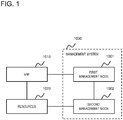
- the management system 1000 includes a first management node 1001 and a second management node 1002.
- the first management node 1001 instructs the second management node 1002 to perform processing for managing resources 1020 for a virtualised network function (VNF) 1010.
- VNF virtualised network function
- the second management node 1002 performs the processing for managing the resources 1020 for the VNF 1010. Specifically, in a case that the VNF 1010 is created, updated, terminated, or the like, the second management node 1002 performs processing such as securing, allocating, releasing, or the like of the resources for the VNF 1010.
- the second management node 1002 When the second management node 1002 is in congestion, at least one of the first management node 1001 and the second management node 1002 performs processing for suppressing communication traffic between the first management node 1001 and the second management node 1002. Suppressing communication traffic between the first management node 1001 and the second management node 1002 reduces load of the second management node 1002 and hence easing the congestion. For example, the first management node 1001 reduces requests (instructions) from the first management node 1001 to the second management node 1002, which thereby suppresses the communication traffic (amount) between the first management node 1001 and the second management node 1002.
- the second management node 1002 When the second management node 1002 is in congestion, the second management node 1002 may not be able to appropriately manage the resources 1020 for the VNF 1010. The second management node 1002 being not able to appropriately manage the resources 1020 for the VNF 1010 may cause a failure in performing processing related to VNF lifecycle.
- the congestion of the second management node 1002 can be eased. Consequently, the second management node 1002 is able to appropriately manage the resources 1020 for the VNF 1010.
- the second management node 1002 appropriately managing the resources 1020 for the VNF 1010 consequently contributes to preventing a failure in performing the processing related to VNF lifecycle.
- the management system 1000 contributes to appropriately performing the processing related to VNF lifecycle.
- FIG. 2 is a block diagram illustrating an example of an entire configuration of a communication system 10 according to the present example embodiment.
- the communication system 10 includes a management system 1, a virtualised network function (VNF) 2, and resources 3 for controlling performance of the VNF 2.
- the management system 1 includes a first management node 11 and a second management node 12.
- the VNF 2 is a unit implementing a network function that is virtualised.
- the VNF 2 may be a function of network equipment, such as a router, a gateway, a firewall, or a load balancer, implemented in a virtualised environment.
- the resources 3 are a virtual machine and hardware, configured to implement and control the VNF 2.
- the virtual machine performs processing in a virtualised environment to implement and control the VNF 2.
- the management system 1 manages the lifecycle of the VNF 2, based on an instruction from a client 4.
- the lifecycle of the VNF 2 includes processing such as creation, update, and termination of the VNF 2.
- the client 4 is, for example, a terminal apparatus used by a maintenance worker of the management system 1, a host apparatus of the management system 1, or the like.
- the first management node 11 instructs the second management node 12 to perform processing for managing the resources for the VNF 2. In other words, the first management node 11 instructs the second management node 12 to perform processing for managing the resources 3.
- the second management node 12 performs the processing for managing the resources for the VNF 2 (i.e., the resources 3).
- At least one of the first management node 11 and the second management node 12 performs processing for suppressing communication traffic between the first management node 11 and the second management node 12.
- at least one of the first management node 11 and the second management node 12 removes the suppression of the communication traffic between the first management node 11 and the second management node 12.
- FIG. 3 is a block diagram illustrating an example of an inner configuration of the communication system 10 according to the present example embodiment.
- the communication system 10 includes the management system 1, a VNF layer 5, and a resource layer 6.
- the VNF layer 5 implements the VNF 2 illustrated in FIG. 2 .
- the resource layer 6 implements the resources 3 illustrated in FIG. 2 .
- the management system 1, the VNF layer 5, and the resource layer 6 communicate with a communication service node 7.
- FIG. 3 is an example of the communication system 10 according to the present example embodiment and is not intended to limit the communication system 10 according to the present example embodiment to the configuration illustrated in FIG. 3 .
- VNF layer 5 is described in detail.
- the VNF layer 5 includes virtual nodes (VNFs) (51-a to 51-c) and virtual management nodes (element management systems (EMSs)) (52-a to 52-c).
- VNFs virtual nodes
- EMSs virtual management nodes
- FIG. 3 three virtual nodes (VNFs) (51-a to 51-c) and three virtual management nodes (EMSs) (52-a to 52-c) are illustrated. However, this does not intend to limit each of the number of the virtual nodes (VNFs) 51 and the number of virtual management nodes (EMSs) 52 to three.
- the virtual node (VNF) 51 By configuring (implementing) the virtual node (VNF) 51 with a network function, the virtual node (VNF) 51 implements a VNF.
- the virtual machine performs the network function configured in the virtual node (VNF) 51 by using the virtual node (VNF) 51 configured with the network function.
- one virtual node (VNF) 51 may, of course, correspond to two or more virtual machines.
- one virtual machine may, of course, use two or more virtual nodes (VNFs) 51.
- the virtual management node (EMS) 52 manages the virtual node (VNF) 51. Specifically, the virtual management node (EMS) 52 manages the network function configured in the virtual node (VNF) 51. Each virtual management node (EMS) 52 may manage one virtual node (VNF) 51. Alternatively, one virtual management node (EMS) 52 may manage two or more virtual nodes (VNFs) 51.
- the resource layer 6 includes a control part (hardware) 61, a storage part (hardware) 62, a communication part (hardware) 63, a virtualisation layer 64, a virtual control part 65, a virtual storage part 66, and a virtual communication part 67.
- the virtual machine includes the virtual control part 65, the virtual storage part 66, and the virtual communication part 67.
- the resource layer 6 may include two or more virtual machines.
- the control part (hardware) 61, the storage part (hardware) 62, and the communication part (hardware) 63 are also referred to simply as "hardware” when there is no need for distinction.
- the virtual control part 65, the virtual storage part 66, and the virtual communication part 67 are also referred to simply as a "virtual machine" when there is no need for distinction.
- the control part (hardware) 61 is configured to control an information processing apparatus (computer) constituting the resource layer 6.
- the control part (hardware) 61 is implemented with a central processing unit (CPU) and the like.
- the storage part (hardware) 62 is configured to store information necessary for causing the information processing apparatus constituting the resource layer 6 to operate.
- the storage part (hardware) 62 is implemented with a magnetic disk apparatus, an optical disk apparatus, or a semiconductor memory.
- the communication part (hardware) 63 is configured to control communication processing of the control part (hardware) 61 and the storage part (hardware) 62 with the virtual machine, the management system 1, the communication service node 7, the client 4, and the like.
- the communication part (hardware) 63 is configured to also control communication processing with a network different from the communication system 10 according to the present example embodiment.
- the communication part (hardware) 63 is implemented with a network interface card (NIC) or the like.
- the virtualisation layer 64 is configured to perform processing for abstracting hardware.
- the virtualisation layer 64 is configured to further relay connection between the hardware and the virtual machine and the VNF.
- the hardware accesses the virtual machine and the VNF via the virtualisation layer 64 to perform processing configured in the virtual machine and the VNF.
- the virtual control part 65 performs the VNF configured in the virtual node 51.
- the virtual storage part 66 stores information necessary for performing the VNF.
- the virtual communication part 67 controls communication processing with the management system 1, the communication service node 7, the client 4, and the like.
- the communication service node 7 provides communication service.
- a communication provider manages the communication service node 7.
- the communication service node 7 may function as an operations support systems and business support systems (OSS/BSS) defined in the ETSI NFV standards (Non-Patent Literature 1).
- OSS/BSS operations support systems and business support systems
- the management system 1 includes the first management node 11 and the second management node 12.
- the first management node 11 includes a system management node 111 and one or two or more function management nodes 112.
- the second management node 12 includes a resource management node 121.
- the system management node 111 accepts an instruction of VNF creation or the like from the client 4.
- the system management node 111 inquires the function management node 112 managing a target VNF about whether or not the instructed processing is possible.
- the system management node 111 instructs the resource management node 121 to perform processing for securing resources necessary for the target VNF.
- Each function management node 112 manages VNF lifecycle.
- the function management node 112 may be provided in the management system 1 for each VNF.
- one resource management node 121 may manage lifecycles of two or more VNFs.
- the function management node 112 determines whether or not the processing related to VNF lifecycle is possible. The function management node 112 then responds to the system management node 111 about whether or not the processing related to VNF lifecycle is possible. The function management node 112 instructs the resource management node 121 to perform processing for allocating resources to the target VNF. Furthermore, the function management node 112 performs the processing related to VNF lifecycle, such as VNF creation.
- the resource management node 121 performs processing for managing resources for a VNF. Specifically, in response to an instruction from the system management node 111, the resource management node 121 performs the processing for securing resources necessary for a target VNF. In response to the instruction from the function management node 112, the resource management node 121 performs the processing for allocating resources to the target VNF.
- the resource management node 121 secures, for the target VNF, VNF resources with a functional configuration smaller than a requested functional configuration.
- the resource management node 121 then allocates the resources smaller than the resources for the requested functional configuration, to the target VNF.
- the resource management node 121 secures, for the target VNF, VNF resources satisfying the originally requested functional configuration.
- the resource management node 121 then allocates the resources satisfying the originally requested functional configuration, to the target VNF.
- the system management node 111 may be implemented as an orchestrator defined in the ETSI NFV standards (Non-Patent Literature 1).
- the function management node 112 may be implemented as a VNF manager defined in the ETSI NFV standards.
- the resource management node 121 may be implemented as a virtualised infrastructure manager (VIM) defined in the ETSI NFV standards.
- VIM virtualised infrastructure manager
- VNF instantiation processing is described as an example in the following description, this does not intend to limit processing of the management system 1 according to the present example embodiment to the VNF instantiation processing.
- the processing in the management system 1 according to the present example embodiment may be applied to VNF scale out processing and healing processing.
- the operations of the communication system 10 to be described below are examples of the communication system 10 according to the present example embodiment, and the description is not intended to limit operations of the communication system 10 to the operations to be described below.
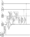
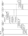
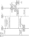
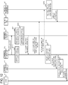
- FIGS. 4 , 5 , and 6 are sequence diagrams illustrating examples of the operations of the communication system 10 according to the present example embodiment.
- Step S001 the client 4 instructs the system management node 111 to create a VNF.
- the system management node 111 Upon receipt of a VNF creation instruction from the client 4, the system management node 111 instructs the function management node 112 to create the VNF (Step S002). Specifically, the system management node 111 instructs the function management node 112 that manages the VNF for which creation is instructed, to create the VNF.
- Step S003 the function management node 112 transmits a request for permission to create the VNF to the system management node 111.
- the request for permission to create the VNF includes a functional configuration implementing the creation-target VNF and information of resources satisfying the functional configuration.
- Step S004 the system management node 111 requests the resource management node 121 to reserve the resources satisfying the requested functional configuration.
- Step S005 the resource management node 121 determines whether or not the resource management node 121 is in congestion. When the resource management node 121 is not in congestion (No at branch in Step S005), the resource management node 121 secures the resources satisfying the requested functional configuration (Step S006). Then, the processing advances to Step S008.
- Step S005 when the resource management node 121 is in congestion (Yes at branch in Step S005), the resource management node 121 secures resources satisfying a functional configuration smaller than the requested functional configuration (Step S007).
- Step S008 the system management node 111 is notified of information of the secured resources.
- Step S009 the system management node 111 determines whether or not the VNF is configurable by using the resources with the notified functional configuration (Step S009).
- the system management node 111 notifies, via the function management node 112, the resource management node 121 that the VNF is not configurable (Steps S010 and S011). Then, when the resource management node 121 is in congestion, the resource management node 121 suspends performance of the VNF creation processing until the congestion is solved (Step S012).
- Step S009 when the VNF is configurable by using the resources with the notified functional configuration (Yes at branch in Step S009), the system management node 111 notifies the function management node 112 that the VNF is configurable and about the notified functional configuration and resources (Step S013). Then, the processing advances to Step S021 illustrated in FIG. 5 .
- Step S021 the function management node 112 determines whether or not the notified functional configuration is configurable. In a case that the notified functional configuration is not configurable (No at branch in Step S021), the function management node 112 notifies the resource management node 121 that the VNF is not configurable (Step S022). Then, the resource management node 121 suspends performance of the VNF creation processing until the congestion is solved (Step S023).
- the function management node 112 requests to allocate resources satisfying the notified functional configuration (Step S024). Specifically, the function management node 112 requests to allocate the resources secured by the resource management node 121 in Step S007 to the creation-target VNF.
- the smaller the size of the resources requested to be allocated is, the smaller the communication traffic between the function management node 112 and the resource management node 121 is. In other words, the smaller the size of the resources requested to be allocated is, the smaller the communication load of the resource management node 121 is.
- Step S025 the resource management node 121 allocates the resources requested to be allocated, to the creation-target VNF. Specifically, the resource management node 121 allocates the resources secured in Step S007 to the creation-target VNF.
- Step S026 the resource management node 121 notifies the function management node 112 of completion of the resource allocation.
- the function management node 112 configures, in the virtual node (VNF) 51, information necessary for assigning the VNF and creates the VNF (Step S027).
- the function management node 112 then notifies the virtual management node (EMS) 52 of completion of the VNF creation (Step S028). Then, the processing advances to Step S041 illustrated in FIG. 6 .
- Step S041 When the function management node 112 notifies the virtual management node (EMS) 52 of completion of VNF configuration, the function management node 112 and the virtual management node (EMS) 52 add the virtual node (VNF) 51 configured with the VNF, as a management target (Step S041).
- the virtual management node (EMS) 52 then configures application information in the virtual node (VNF) 51 (Step S042).
- the application information is information of an application that causes the VNF to operate or the like.
- the function management node 112 notifies the system management node 111 of completion of the VNF configuration (Step S043).
- the system management node 111 then associates the VNF with the resource management node 121 and a resource pool (Step S044).
- the resource management node 121 secures the resources satisfying the originally requested functional configuration (functional configuration requested in Step S004) (Step S045).
- the resource management node 121 then notifies the function management node 112 of completion of the resource securing (Step S046).
- the function management node 112 then starts scale out processing to create the VNF that satisfies the originally requested functional configuration (Step S047).
- the management system 1 when the resource management node 121 is in congestion, VNF resources with a functional configuration smaller than a requested functional configuration are secured. Consequently, load of the resource management node 121 is reduced. Moreover, the smaller the size of VNF resources to be secured is, the more the communication traffic between the function management node 112 and the resource management node 121 is reduced. Consequently, the management system 1 according to the present example embodiment eases congestion of the resource management node 121 and thereby contributes to preventing a failure in performing the processing related to VNF lifecycle. Hence, the management system 1 according to the present example embodiment contributes to appropriately performing the processing related to VNF lifecycle.
- the present example embodiment is a mode in which, when a node configured to manage VNF resources is in congestion, a management system suspends, after accepting a request for processing related to VNF lifecycle, performance of the processing.
- a management system suspends, after accepting a request for processing related to VNF lifecycle, performance of the processing.
- FIG. 2 An entire configuration of a communication system 10 according to the present example embodiment is as illustrated in FIG. 2 .
- An inner configuration of the communication system 10 according to the present example embodiment is as illustrated in FIG. 3 .
- a first management node 11 (system management node 111 and function management node 112) suspends performance of VNF management processing until the congestion is solved.
- the first management node 11 (system management node 111 and function management node 112) performs processing for suppressing communication between the first management node 11 and the resource management node 121.
- the resource management node 121 in congestion receives a signal (request for processing related to VNF lifecycle) from the system management node 111 or the function management node 112, the resource management node 121 responds that the resource management node 121 is in congestion.
- the transmission source of the signal i.e., the system management node 111 or the function management node 112 then suppresses subsequent signal transmission and suspends performance of the processing related to VNF lifecycle.
- the system management node 111 then notifies the requester of the processing related to VNF lifecycle that the resource management node 121 is in congestion and that performance of the processing related to VNF lifecycle is suspended.
- the system management node 111 and the function management node 112 start performance of VNF management processing.
- the resource management node 121 when the congestion of the resource management node 121 is solved, the resource management node 121 notifies the system management node 111 or the function management node 112 that the congestion of the resource management node 121 is solved.
- the system management node 111 or the function management node 112 thereby recognizes that the congestion of the resource management node 121 is solved and resumes (starts) the suspended processing related to VNF lifecycle.
- the system management node 111 then notifies the requester of the processing related to VNF lifecycle that the congestion of the resource management node 121 is solved and that the processing related to VNF lifecycle is resumed (started).
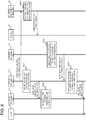
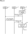
- FIGS. 7 , 8 , and 9 are sequence diagrams illustrating examples of the operations of the communication system 10 according to the present example embodiment.
- VNF instantiation processing is described as an example in the following description, this does not intend to limit processing of the management system 1 according to the present example embodiment to the VNF instantiation processing.
- the processing in the management system 1 according to the present example embodiment may be applied to VNF scale out processing and healing processing.
- the operations of the communication system 10 to be described below are examples of the communication system 10 according to the present example embodiment, and the description is not intended to limit operations of the communication system 10 to the operations to be described below.
- the processing in Step S001 to Step S004 illustrated in FIG. 7 is similar to the processing in Step S001 to Step S004 illustrated in FIG. 4 , and hence detailed descriptions thereof are omitted.
- Step S005 illustrated in FIG. 7
- Step S101 the resource management node 121 secures the resources satisfying the requested functional configuration
- Step S101 When the resource management node 121 secures the resources satisfying a requested functional configuration (Step S101), the resource management node 121 notifies the system management node 111 of information of the secured resources (Step S141). The system management node 111 then notifies the function management node 112 of the notified functional configuration and resources (Step S142). The function management node 112 requests the resource management node 121 to allocate the notified resources (Step S143). The resource management node 121 allocates the resources requested to be allocated, to the creation-target VNF (Step S144). Then, the processing advances to Step S122 illustrated in FIG. 9 .
- Step S102 the resource management node 121 notifies the system management node 111 of the congestion
- Step S103 the function management node 112 of the congestion
- Step S104 the system management node 111 may notify the function management node 112, after notifying the client 4, that the resource management node 121 is in congestion, and thus the notifications may be made in any order.
- the system management node 111 and the function management node 112 suspend performance of the VNF creation processing (Step S105).
- the resource management node 121 secures the resources satisfying the originally requested functional configuration (the functional configuration requested in Step S004) (Step S106).
- the resource management node 121 then notifies the system management node 111 that the congestion is solved (Step S107).
- the system management node 111 then notifies the function management node 112 that the congestion is solved (Step S108).
- the system management node 111 then notifies the client 4 that the congestion is solved and that the VNF creation processing is to be resumed (Step S109).
- the system management node 111 may notify the function management node 112, after notifying the client 4, that the resource management node 121 is in congestion, and thus the notifications may be made in any order.
- Step S110 the function management node 112 requests the resource management node 121 to allocate the resources. Then, the processing advances to Step S121 illustrated in FIG. 9 .
- Step S121 illustrated in FIG. 9 the resource management node 121 allocates the resources requested to be allocated, to the creation-target VNF.
- the processing in Step S122 to Step S124 illustrated in FIG. 9 is similar to the processing in Step S026 to Step S028 illustrated in FIG. 5 , and hence detailed descriptions thereof are omitted below.
- the processing in Step S125 to Step S128 illustrated in FIG. 9 is similar to the processing in Step S041 to Step S044 illustrated in FIG. 6 , and hence detailed descriptions thereof are omitted.
- Step S128 When the system management node 111 associates the VNF with the resource management node 121 and a resource pool (Step S128), the system management node 111 notifies the client 4 of completion of the configuration (Step S129).
- the management system 1 when the resource management node 121 is in congestion, the management system 1 according to the present example embodiment suspends, after accepting a request for processing related to VNF lifecycle, performance of the processing.
- the resource management node 121 suspending performance of the processing stops performance and request of processing in subsequent steps. Consequently, the management system 1 according to the present example embodiment eases congestion of the resource management node 121 and thereby contributes to preventing a failure in performing the processing related to VNF lifecycle.
- the management system 1 according to the present example embodiment contributes to appropriately performing the processing related to VNF lifecycle.
- the present example embodiment is a mode in which, when a node configured to manage VNF resources is in congestion, a management system reserves, after accepting a request for processing related to VNF lifecycle, performance of the processing and suspends the performance of the processing related to VNF lifecycle.
- a management system reserves, after accepting a request for processing related to VNF lifecycle, performance of the processing and suspends the performance of the processing related to VNF lifecycle.
- FIG. 2 An entire configuration of a communication system 10 according to the present example embodiment is as illustrated in FIG. 2 .
- An inner configuration of the communication system 10 according to the present example embodiment is as illustrated in FIG. 3 .
- a resource management node 121 when a resource management node 121 is in congestion and processing for managing VNF resources is instructed by a first management node 11 (system management node 111 and function management node 112), the resource management node 121 reserves performance of the instructed processing and suspends the performance of the instructed processing until the congestion is solved.
- the resource management node 121 receives a signal (request for processing related to VNF lifecycle) from the first management node 11 (system management node 111 and function management node 112) in congestion, the resource management node 121 accepts the request for the processing and reserves performance of the processing. The resource management node 121 then responds that the performance of the processing is reserved. The resource management node 121 then suspends processing in subsequent steps. The system management node 111 then notifies the requester of the processing related to VNF lifecycle that the performance of the processing related to VNF lifecycle is suspended.
- the system management node 111 and the function management node 112 start performance of VNF management processing.
- the resource management node 121 performs VNF resource allocation.
- the resource management node 121 then resumes (starts) the suspended processing related to VNF lifecycle.
- the first management node 11 system management node 111 and function management node 112 also resumes (starts) the suspended processing related to VNF lifecycle.
- the system management node 111 notifies the requester of the processing of completion of the processing.
- FIGS. 10 , 11 , and 12 are sequence diagrams illustrating examples of the operations of the communication system 10 according to the present example embodiment.
- VNF instantiation processing is described as an example in the following description, this does not intend to limit processing of the management system 1 according to the present example embodiment to the VNF instantiation processing.
- the processing in the management system 1 according to the present example embodiment may be applied to VNF scale out processing and healing processing.
- the operations of the communication system 10 to be described below are examples of the communication system 10 according to the present example embodiment, and the description is not intended to limit operations of the communication system 10 to the operations to be described below.
- the processing in Step S001 to Step S004 illustrated in FIG. 10 is similar to the processing in Step S001 to Step S004 illustrated in FIG. 4 , and hence detailed descriptions thereof are omitted.
- Step S005 illustrated in FIG. 10
- the resource management node 121 secures resources satisfying the requested functional configuration (Step S201). Then, the processing advances to Step S231 illustrated in FIG. 11 .
- Step S201 When the resource management node 121 secures the resources satisfying a requested functional configuration (Step S201), the resource management node 121 notifies the system management node 111 of information of the secured resources (Step S231). The system management node 111 then notifies the function management node 112 of the notified functional configuration and resources (Step S232). The function management node 112 requests the resource management node 121 to allocate the notified resources (Step S233). The resource management node 121 allocates the resources requested to be allocated, to the creation-target VNF (Step S234). Then, the processing advances to Step S213 illustrated in FIG. 12 .
- the resource management node 121 reserves performance of VNF creation processing (Step S202).
- the resource management node 121 then notifies the system management node 111 that the performance of the VNF creation processing is reserved (Step S203).
- the system management node 111 then notifies the function management node 112 that the performance of the VNF creation processing is reserved (Step S204).
- the system management node 111 further notifies the client 4 that the performance of the VNF creation processing is to be suspended (Step S205).
- Step S206 the system management node 111 suspends the performance of the VNF creation processing.
- Step S207 the function management node 112 requests the resource management node 121 to allocate the resources. Then, the processing advances to Step S211 illustrated in FIG. 12 .
- Step S211 When the function management node 112 requests the resource management node 121 to allocate resources, the function management node 112 and the resource management node 121 suspend performance of the VNF creation processing (Step S211).
- Step S212 the resource management node 121 performs resource allocation (Step S212).
- Step S213 the resource management node 121 notifies the function management node 112 of completion of the resource allocation.
- the processing in Step S214 and Step S215 illustrated in FIG. 12 is similar to the processing in Step S027 and Step S028 illustrated in FIG. 5 , and hence detailed descriptions thereof are omitted below.
- the processing in Step S216 to Step S219 illustrated in FIG. 12 is similar to the processing in S041 to Step S044 illustrated in FIG. 6 , and hence detailed descriptions thereof are omitted.
- Step S219 When the system management node 111 associates the VNF with the resource management node 121 and a resource pool (Step S219), the system management node 111 notifies the client 4 of completion of the configuration (Step S220).
- the management system 1 when the resource management node 121 is in congestion, the management system 1 according to the present example embodiment reserves performance of the processing and suspends the performance of the processing related to VNF lifecycle. Reserving performance of the processing related to VNF lifecycle and suspending the performance of the processing stop performance and request of processing in subsequent steps. Consequently, the management system 1 according to the present example embodiment eases congestion of the resource management node 121 and thereby contributes to preventing a failure in performing the processing related to VNF lifecycle. Hence, the management system 1 according to the present example embodiment contributes to appropriately performing the processing related to VNF lifecycle.
- the present example embodiment is a mode in which an upper limit of response wait time is increased in accordance with response time from a node configured to manage VNF resources to thereby ease congestion of the node.
- descriptions of parts overlapping those in the above-described example embodiments are omitted in the description of the present example embodiment.
- the same constituent components as those in the above-described example embodiments are denoted by the same reference signs, and descriptions thereof are omitted, in the description of the present example embodiment.
- descriptions of the same advantageous effects as those in the above-described example embodiments are also omitted in the description of the present example embodiment.
- FIG. 2 An entire configuration of a communication system 10 according to the present example embodiment is as illustrated in FIG. 2 .
- An inner configuration of the communication system 10 according to the present example embodiment is as illustrated in FIG. 3 .
- a first management node 11 determines whether or not the resource management node 121 is in congestion, based on a statistic (e.g., the average value) of response times of the resource management node 121.
- the first management node 11 When the first management node 11 (system management node 111 or function management node 112) determines that the resource management node 121 is in congestion, the first management node 11 (system management node 111 or function management node 112) extends (increases) the upper limit of response wait time from the resource management node 121. In contrast, when the first management node 11 (system management node 111 or function management node 112) determines that the resource management node 121 is not in congestion, the first management node 11 (system management node 111 or function management node 112) configures the upper limit of response wait time from the resource management node 121 at a predetermined time period (configures the upper limit of response wait time back to the upper limit of response wait time before the increase). Note that the upper limit of response wait time means an upper limit of time period for the system management node 111 or the function management node 112 to wait for a response from the resource management node 121.
- the first management node 11 (system management node 111 or function management node 112) stores a history of response time including a predetermined number of response times for communication with the resource management node 121.
- the history of the response time is assumed to be a history of response time including a predetermined number of response times before the last communication with the resource management node 121.
- the first management node 11 When the first management node 11 (system management node 111 or function management node 112) communicates with the resource management node 121, the first management node 11 (system management node 111 or function management node 112) compares a time period for a response from the resource management node 121 with a statistic of the stored response times to thereby determine whether or not the resource management node 121 is in congestion.
- the first management node 11 determines whether or not the time period for a response from the resource management node 121 exceeds the average value of the stored response times. When the time for a response from the resource management node 121 exceeds the average value of the stored response times, the first management node 11 (system management node 111 or function management node 112) determines that the resource management node 121 is in congestion. In contrast, when the time for a response from the resource management node 121 is equal to or shorter than the average value of the stored response times, the first management node 11 (system management node 111 or function management node 112) determines that the resource management node 121 is not in congestion.
- FIGS. 13 and 14 are sequence diagrams illustrating examples of the operations of the communication system 10 according to the present example embodiment.
- VNF instantiation processing is described as an example in the following description, this does not intend to limit processing of the management system 1 according to the present example embodiment to the VNF instantiation processing.
- the processing in the management system 1 according to the present example embodiment may be applied to VNF scale out processing and healing processing.
- the operations of the communication system 10 to be described below are examples of the communication system 10 according to the present example embodiment, and the description is not intended to limit operations of the communication system 10 to the operations to be described below.
- the processing in Step S001 to Step S004 illustrated in FIG. 13 is similar to the processing in Step S001 to Step S004 illustrated in FIG. 4 , and hence detailed descriptions thereof are omitted.
- Step S301 When the resource management node 121 accepts a request to reserve resources from the system management node 111, the resource management node 121 responds to the system management node 111 that resource reservation is accepted (Step S301 illustrated in FIG. 13 ).
- Step S302 the system management node 111 calculates the average value of the response times for communication with the resource management node 121, based on the history of response time including a predetermined number of response times.
- Step S303 when the response time exceeds the calculated average value in the last communication with the resource management node 121 (e.g., processing in Step S301), the system management node 111 extends (increases) the upper limit of response wait time.
- Step S304 when the response time is equal to or shorter than the calculated average value in the last communication with the resource management node 121 (e.g., processing in Step S301), the system management node 111 configures the upper limit of response wait time at an original upper limit of time period (predetermined upper limit of time period).
- Step S305 the system management node 111 transmits a permission to create the VNF to the function management node 112. Then, the processing advances to Step S311 illustrated in FIG. 14 .
- the function management node 112 When the function management node 112 receives the permission to create the VNF from the system management node 111, the function management node 112 requests the resource management node 121 to allocate the resources (Step S311).
- Step S312 the resource management node 121 allocates the resources requested to be allocated, to the creation-target VNF.
- Step S313 the resource management node 121 notifies the function management node 112 of completion of the resource allocation.
- Step S314 the function management node 112 calculates the average value of the response times for communication with the resource management node 121, based on the history of response time including a predetermined number of response times.
- Step S315 when the response time exceeds the calculated average value in the last communication with the resource management node 121 (e.g., processing in Step S313), the function management node 112 increases the upper limit of response wait time.
- Step S316 when the response time is equal to or shorter than the calculated average value in the last communication with the resource management node 121 (e.g., processing in Step S313), the function management node 112 configures the upper limit of response wait time at an original upper limit of time period (predetermined upper limit of time period).
- the processing in Step S317 and Step S318 illustrated in FIG. 14 is similar to the processing in Step S027 and Step S028 illustrated in FIG. 5 , and hence detailed descriptions thereof are omitted below.
- the processing in Step S319 to Step S322 illustrated in FIG. 14 is similar to the processing in Step S041 to Step S044 illustrated in FIG. 6 , and hence detailed descriptions thereof are omitted.
- Step S322 When the system management node 111 associates the VNF with the resource management node 121 and a resource pool (Step S322), the system management node 111 notifies the client 4 of completion of the configuration (Step S323).
- the management system 1 increases the upper limit of response wait time of the first management node 11 (system management node 111 or function management node 112) in accordance with time for a response from the resource management node 121 to the first management node 11 (system management node 111 or function management node 112).
- Increasing the upper limit of response wait time of the first management node 11 suppresses the communication traffic between the first management node 11 (system management node 111 or function management node 112) and the resource management node 121.
- the management system 1 according to the present example embodiment eases congestion of the resource management node 121 and thereby contributes to preventing a failure in performing the processing related to VNF lifecycle. Hence, the management system 1 according to the present example embodiment contributes to appropriately performing the processing related to VNF lifecycle.
- the system management node 111 may manage information of resources necessary for a functional configuration of a VNF.
- the system management node 111 and the function management node 112 may manage information of resources necessary for a functional configuration of a VNF.
- a management system including: a first management node configured to instruct a second management node to perform processing for managing resources for a virtualised network function; and the second management node configured to perform, in response to an instruction from the first management node, the processing for managing the resources for the virtualised network function, wherein, when the second management node is in congestion, at least one of the first management node and the second management node performs processing for suppressing communication traffic between the first management node and the second management node.
- the management system in which, when the second management node is in congestion, the second management node secures resources for the virtualised network function with a functional configuration smaller than a requested functional configuration.
- the management system in which, when the second management node is in congestion, the first management node suspends performance of the processing for managing the resources for the virtualised network function until the congestion is solved.
- the management system in which, when the second management node is in congestion and the processing for managing the resources for the virtualised network function is instructed from the first management node, the second management node reserves performance of the instructed processing and suspends the performance of the instructed processing until the congestion is solved.
- the management system in which the first management node calculates, based on a record of a predetermined number of response times, an average value of the response times, and determines, when a response time of the second management node exceeds the average value of the response times, that the second management node is in congestion and extends (increases) an upper limit of response wait time from the second management node.
- the management system in which, when the congestion of the second management node is solved, at least one of the first management node and the second management node removes suppression of communication traffic between the first management node and the second management node.
- a management apparatus that instructs a predetermined apparatus to perform processing for managing resources for a virtualised network function, wherein, when the predetermined apparatus is in congestion, the management apparatus performs processing for suppressing communication traffic between the predetermined apparatus and the management apparatus itself.
- the management apparatus in which the management apparatus manages the virtualised network function and suspends, when the predetermined apparatus is in congestion, performance of the processing for managing the virtualised network function until the congestion is solved.
- the management apparatus determines, based on a statistic of response times of the predetermined apparatus, whether or not the predetermined apparatus is in congestion, and increases, when the predetermined apparatus is in congestion, an upper limit of response wait time from the predetermined node.
- the management apparatus in which, when the congestion of the predetermined apparatus is solved, the management apparatus removes suppression of communication traffic between the predetermined apparatus and the management apparatus itself.
- a management apparatus that performs processing for managing resources for a virtualised network function in response to an instruction from a predetermined apparatus, wherein, when the management apparatus itself is in congestion, the management apparatus performs processing for suppressing communication traffic between the predetermined apparatus and the management apparatus itself.
- the management apparatus in which, when the management apparatus itself is in congestion, the management apparatus secures resources for the virtualised network function with a functional configuration smaller than a requested functional configuration.
- the management apparatus in which, when the management apparatus itself is in congestion and the processing for managing the resources for the virtualised network function is instructed from the predetermined apparatus, the management apparatus reserves a request for the instructed processing and suspends performance of the instructed processing until the congestion is solved.
- the management apparatus in which, when the congestion of the management apparatus itself is solved, the management apparatus removes suppression of communication traffic between the predetermined apparatus and the management apparatus itself.
- a management method performed by a management system including a first management node and a second management node including the step of, suppressing communication traffic between the first management node and the second management node when the second management node is in congestion, wherein the first management node configured to instruct a second management node to perform processing for managing resources for a virtualised network function and the second management node configured to perform, in response to an instruction from the first management node, the processing for managing the resources for the virtualised network function.
- the management method including the step of securing resources for the virtualised network function with a functional configuration smaller than a requested functional configuration when the second management node is in congestion.
- the management method including the step of suspending performance of the processing for managing the resources for the virtualised network function until the congestion is solved when the second management node is in congestion.
- the management method including the step of reserving performance of the processing for managing the resources for the virtualised network function and suspending the performance of the instructed processing until the congestion is solved when the second management node is in congestion.
- the management method including the steps of determining, based on a statistic of response times of the second management node, whether or not the second management node is in congestion; and extending (increasing) an upper limit of response wait time from the second management node when the second management node is in congestion.
- the management method including the step of removing suppression of communication traffic between the first management node and the second management node when the congestion of the second management node is solved.
- Mode 21 As the mode described in Mode 15, can be developed to the modes described in Modes 16 to 20.
- Patent Literatures and Non-Patent Literature are incorporated herein by reference. Making a change and adjustment of the example embodiments is allowed within the framework of the entire disclosure (including the scope of the claims) of the present invention, and also based on a basic technical concept of the present invention. Further, various combination or selection of various disclosed elements (including each element of each claim, each element of each example embodiment, each element of each drawing, and the like) is allowed within the framework of the entire disclosure of the present invention. Specifically, as a matter of course, the present invention encompasses various modifications and amendments that may be achieved by a person skilled in the art based on the entire disclosure including the scope of the claims and the technical concept. Regarding a numerical range described herein, in particular, it should be interpreted that any numerical value or any smaller range included within the range is specifically described even without particular description.
Landscapes
- Engineering & Computer Science (AREA)
- Physics & Mathematics (AREA)
- Theoretical Computer Science (AREA)
- Computer Networks & Wireless Communication (AREA)
- Signal Processing (AREA)
- Software Systems (AREA)
- General Physics & Mathematics (AREA)
- Data Mining & Analysis (AREA)
- Computational Mathematics (AREA)
- Mathematical Analysis (AREA)
- Mathematical Physics (AREA)
- Pure & Applied Mathematics (AREA)
- General Engineering & Computer Science (AREA)
- Mathematical Optimization (AREA)
- Evolutionary Biology (AREA)
- Life Sciences & Earth Sciences (AREA)
- Operations Research (AREA)
- Probability & Statistics with Applications (AREA)
- Bioinformatics & Computational Biology (AREA)
- Algebra (AREA)
- Bioinformatics & Cheminformatics (AREA)
- Databases & Information Systems (AREA)
- Environmental & Geological Engineering (AREA)
- Data Exchanges In Wide-Area Networks (AREA)
Abstract
Description
- The present invention claims priority based on Japanese Patent Application No.
2017-017066 (filed on February 1, 2017 - The present invention relates to a management system, a management apparatus, a management method, and a program.
- The use of network function virtualisation (NFV) for virtualising functions of network equipment (such as routers, gateways, firewalls, and load balancers) has been increasing. In NFV, a function of network equipment is performed on a virtual machine, and thereby the virtual machine performs the function of the network equipment alternatively.
- Non-Patent
Literature 1 discloses a configuration for implementing NFV. In the configuration described inNPL 1, a network functions virtualisation orchestrator (NFVO), a virtualised network functions manager (VNFM), and a virtualised infrastructure manager (VIM) perform virtual resource management, virtualised network functions (VNF) lifecycle management, and the like. Specifically, the NFVO and the VNFM request the VIM to perform virtual resource management and/or VNF lifecycle management. The VIM then performs the virtual resource management and/or the VNF lifecycle management. -
Patent Literature 1 describes a technique for performing VNF scale out in NFV environment. Specifically, in the technique described inPatent Literature 1, the VNFM includes a VNFM surplus resource information database (DB) to store surplus resource information of surplus resources, which are surplus virtual resources reserved in a VIM in advance. Upon receipt of notification that virtual resources are in short from the VNF, the VNFM identifies a virtual server with the reserved surplus resources, based on the surplus resource information stored in the VNFM surplus resource information DB, and transmits an instruction to provide the identified virtual server to the VIM. Upon receipt of the instruction to provide the virtual server from the VNFM, the VIM provides the virtual server. -
Patent Literature 2 describes a technique for performing, even when switching of a plurality of virtual machines or the like has been performed by various control apparatuses, control for acquiring the latest data from a database. Specifically, in the technique described inPatent Literature 2, an NFVO stores delay information indicating synchronization delay between storages. A VNF accepts a transmission request from a mobile communication terminal. In response to the accepted transmission request, the VNF further accesses at least one database apparatus among a plurality of database apparatuses. The VNF further acquires the delay information from the NFVO and also receives a switching request. The VNF is triggered by the acceptance of the switching request to control for acquiring the latest data from the database apparatus, based on the delay information. -
- Patent Literature 1:
Japanese Patent Kokai Publication No.JP2015-194949A - Patent Literature 2:
Japanese Patent Kokai Publication No.JP2015-222481A - Non-Patent Literature 1 :
"Network Functions Orchestration (NFV); Management and Orchestration; Functional requirements specification", ETSI GS NFV-IFA 010 V2.1.1 (2016-04), [online] searched on December 28, 2016, the Internet <URL: http://www.etsi.org/deliver/etsi_gs/NFV-IFA/001_099/010/02.01.01_60 /gs_NFV-IFA010v020101p.pdf> - Note that the disclosures in the above-mentioned Patent Literatures and Non-Patent Literatures are incorporated herein by reference. The following analysis has been made from a viewpoint of the present invention.
- Regarding the configuration described in
Non-Patent Literature 1, the NFVO and the VNFM are not able to monitor and/or keep track of load of the VIM. For this reason, even when the VIM is overloaded, the NFVO and the VNFM transmit a signal for requesting processing to the VIM in some cases. Consequently, even when the VIM is in congestion, the NFVO and the VNFM transmit a signal for requesting processing to the VIM, which further increases the load of the VIM. The increase in load of the VIM may prevent the VIM for appropriately performing processing related to VNF lifecycle. -
Patent Literatures Patent Literatures - In view of these, an object of the present invention is to provide a management system, a management apparatus, a management method, and a program that contribute to appropriately performing processing related to VNF lifecycle.
- According to a first aspect, a management system is provided. The management system includes a first management node configured to instruct a second management node to perform processing for managing resources for a virtualised network function.
- Moreover, the management system includes the second management node configured to perform, in response to an instruction from the first management node, the processing for managing the resources for virtualised network function.
- In the management system, when the second management node is in congestion, at least one of the first management node and the second management node performs processing for suppressing communication traffic (amount) between the first management node and the second management node.
- According to a second aspect, a management apparatus is provided. The management apparatus instructs a predetermined apparatus to perform processing for managing resources for a virtualised network function. Moreover, the management apparatus performs, when the predetermined apparatus is in congestion, processing for suppressing communication traffic between the predetermined apparatus and the management apparatus itself.
- According to another aspect of the present invention, another management apparatus is provided. The management apparatus performs, in response to an instruction from a predetermined apparatus, processing for managing resources for a virtualised network function. Moreover, the management apparatus performs, when the management apparatus itself is in congestion, processing for suppressing communication traffic between the predetermined apparatus and the management apparatus itself.
- According to a third aspect, a management method is provided, the management method being performed by a management system including a first management node configured to instruct a second management node perform processing for managing resources for a virtualised network function and the second management node configured to perform, in response to an instruction from the first management node, the processing for managing the resources for the virtualised network function.
- The management method includes the step of, when the second management node is in congestion, removing suppression of communication traffic between the first management node and the second management node.
- Note that this method is associated with a particular machine called management node configured to manage resources for a virtualised network function.
- According to a fourth aspect, a program is provided, the program being executed by a management system including a first management node configured to instruct a second management node to perform processing for managing resources for a virtualised network function and the second management node configured to perform, in response to an instruction from the first management node, the processing for managing the resources for the virtualised network function.
- The management program causes the management system to perform, when the second management node is in congestion, processing for suppressing communication traffic between the first management node and the second management node.
- Note that this program may be recoded on a computer-readable storage medium. The storage medium may be a non-transient medium, such as a semiconductor memory, a hard disk, a magnetic recording medium, or an optical recording medium. The present invention may be implemented as a computer program product.
- According to each of the aspects, a management system, a management apparatus, a management method, and a program that contribute to appropriately performing processing related to VNF lifecycle are provided.
-
-
FIG. 1 is a diagram for illustrating an outline of one example embodiment. -
FIG. 2 is a block diagram illustrating an example of an entire configuration of acommunication system 10. -
FIG. 3 is a block diagram illustrating an example of an inner configuration of thecommunication system 10. -
FIG. 4 is a sequence diagram illustrating an example of operations of acommunication system 10 according to a first example embodiment. -
FIG. 5 is a sequence diagram illustrating the example of the operations of thecommunication system 10 according to the first example embodiment. -
FIG. 6 is a sequence diagram illustrating the example of the operations of thecommunication system 10 according to the first example embodiment. -
FIG. 7 is a sequence diagram illustrating an example of operations of acommunication system 10 according to a second example embodiment. -
FIG. 8 is a sequence diagram illustrating the example of the operations of thecommunication system 10 according to the second example embodiment. -
FIG. 9 is a sequence diagram illustrating the example of the operations of thecommunication system 10 according to the second example embodiment. -
FIG. 10 is a sequence diagram illustrating an example of operations of acommunication system 10 according to a third example embodiment. -
FIG. 11 is a sequence diagram illustrating the example of the operations of thecommunication system 10 according to the third example embodiment. -
FIG. 12 is a sequence diagram illustrating the example of the operations of thecommunication system 10 according to the third example embodiment. -
FIG. 13 is a sequence diagram illustrating an example of operations of acommunication system 10 according to a fourth example embodiment. -
FIG. 14 is a sequence diagram illustrating the example of the operations of thecommunication system 10 according to the fourth example embodiment. - First of all, with reference to
FIG. 1 , an outline of one example embodiment is described. Note that the reference signs in the drawings added in this outline are given, as an example, to elements for convenience for the sake of better understanding, and the description of this outline is not intended to provide any particular limitation. Connecting lines between the blocks in each block diagram include both bidirectional and unidirectional connecting lines. Note that an input/output port or an interface is provided at each connection portion of each connecting line although explicit illustration thereof is omitted. - As described above, a management system, a management apparatus, a management method, and a program that contribute to appropriately performing processing related to VNF lifecycle are desired.
- In view of this, a
management system 1000 illustrated inFIG. 1 is provided as an example. Themanagement system 1000 includes afirst management node 1001 and asecond management node 1002. - The
first management node 1001 instructs thesecond management node 1002 to perform processing for managingresources 1020 for a virtualised network function (VNF) 1010. - In response to the instruction from the
first management node 1001, thesecond management node 1002 performs the processing for managing theresources 1020 for theVNF 1010. Specifically, in a case that theVNF 1010 is created, updated, terminated, or the like, thesecond management node 1002 performs processing such as securing, allocating, releasing, or the like of the resources for theVNF 1010. - When the
second management node 1002 is in congestion, at least one of thefirst management node 1001 and thesecond management node 1002 performs processing for suppressing communication traffic between thefirst management node 1001 and thesecond management node 1002. Suppressing communication traffic between thefirst management node 1001 and thesecond management node 1002 reduces load of thesecond management node 1002 and hence easing the congestion. For example, thefirst management node 1001 reduces requests (instructions) from thefirst management node 1001 to thesecond management node 1002, which thereby suppresses the communication traffic (amount) between thefirst management node 1001 and thesecond management node 1002. - When the
second management node 1002 is in congestion, thesecond management node 1002 may not be able to appropriately manage theresources 1020 for theVNF 1010. Thesecond management node 1002 being not able to appropriately manage theresources 1020 for theVNF 1010 may cause a failure in performing processing related to VNF lifecycle. - However, by suppressing communication traffic between the
first management node 1001 and thesecond management node 1002, the congestion of thesecond management node 1002 can be eased. Consequently, thesecond management node 1002 is able to appropriately manage theresources 1020 for theVNF 1010. Thesecond management node 1002 appropriately managing theresources 1020 for theVNF 1010 consequently contributes to preventing a failure in performing the processing related to VNF lifecycle. - Hence, the
management system 1000 contributes to appropriately performing the processing related to VNF lifecycle. - A first example embodiment is described in more detail by using drawings.
-
FIG. 2 is a block diagram illustrating an example of an entire configuration of acommunication system 10 according to the present example embodiment. Thecommunication system 10 according to the present example embodiment includes amanagement system 1, a virtualised network function (VNF) 2, andresources 3 for controlling performance of theVNF 2. Themanagement system 1 includes afirst management node 11 and asecond management node 12. - The
VNF 2 is a unit implementing a network function that is virtualised. For example, theVNF 2 may be a function of network equipment, such as a router, a gateway, a firewall, or a load balancer, implemented in a virtualised environment. - The
resources 3 are a virtual machine and hardware, configured to implement and control theVNF 2. The virtual machine performs processing in a virtualised environment to implement and control theVNF 2. - The
management system 1 manages the lifecycle of theVNF 2, based on an instruction from aclient 4. The lifecycle of theVNF 2 includes processing such as creation, update, and termination of theVNF 2. - The
client 4 is, for example, a terminal apparatus used by a maintenance worker of themanagement system 1, a host apparatus of themanagement system 1, or the like. - The
first management node 11 instructs thesecond management node 12 to perform processing for managing the resources for theVNF 2. In other words, thefirst management node 11 instructs thesecond management node 12 to perform processing for managing theresources 3. - In response to the instruction from the
first management node 11, thesecond management node 12 performs the processing for managing the resources for the VNF 2 (i.e., the resources 3). - When the
second management node 12 is in congestion, at least one of thefirst management node 11 and thesecond management node 12 performs processing for suppressing communication traffic between thefirst management node 11 and thesecond management node 12. When the congestion of thesecond management node 12 is solved, at least one of thefirst management node 11 and thesecond management node 12 removes the suppression of the communication traffic between thefirst management node 11 and thesecond management node 12. - Next, with reference to
FIG. 3 , thecommunication system 10 according to the present example embodiment is described in further detail. -
FIG. 3 is a block diagram illustrating an example of an inner configuration of thecommunication system 10 according to the present example embodiment. - With reference to
FIG. 3 , thecommunication system 10 according to the present example embodiment includes themanagement system 1, aVNF layer 5, and aresource layer 6. TheVNF layer 5 implements theVNF 2 illustrated inFIG. 2 . Theresource layer 6 implements theresources 3 illustrated inFIG. 2 . Themanagement system 1, theVNF layer 5, and theresource layer 6 communicate with a communication service node 7. Note thatFIG. 3 is an example of thecommunication system 10 according to the present example embodiment and is not intended to limit thecommunication system 10 according to the present example embodiment to the configuration illustrated inFIG. 3 . - First, the
VNF layer 5 is described in detail. - The
VNF layer 5 includes virtual nodes (VNFs) (51-a to 51-c) and virtual management nodes (element management systems (EMSs)) (52-a to 52-c). Note that, in the following description, the virtual nodes (VNFs) (51-a to 51-c) are referred to as a virtual node (VNF) 51, and the virtual management nodes (EMSs) (52-a to 52-c) are referred to as a virtual management node (EMS) 52, when there is no need for distinction. Moreover, inFIG. 3 , three virtual nodes (VNFs) (51-a to 51-c) and three virtual management nodes (EMSs) (52-a to 52-c) are illustrated. However, this does not intend to limit each of the number of the virtual nodes (VNFs) 51 and the number of virtual management nodes (EMSs) 52 to three. - By configuring (implementing) the virtual node (VNF) 51 with a network function, the virtual node (VNF) 51 implements a VNF. The virtual machine performs the network function configured in the virtual node (VNF) 51 by using the virtual node (VNF) 51 configured with the network function. Note that one virtual node (VNF) 51 may, of course, correspond to two or more virtual machines. Moreover, one virtual machine may, of course, use two or more virtual nodes (VNFs) 51.
- The virtual management node (EMS) 52 manages the virtual node (VNF) 51. Specifically, the virtual management node (EMS) 52 manages the network function configured in the virtual node (VNF) 51. Each virtual management node (EMS) 52 may manage one virtual node (VNF) 51. Alternatively, one virtual management node (EMS) 52 may manage two or more virtual nodes (VNFs) 51.
- Next, the
resource layer 6 is described in detail. - The
resource layer 6 includes a control part (hardware) 61, a storage part (hardware) 62, a communication part (hardware) 63, avirtualisation layer 64, avirtual control part 65, avirtual storage part 66, and avirtual communication part 67. - The virtual machine includes the
virtual control part 65, thevirtual storage part 66, and thevirtual communication part 67. Here, theresource layer 6 may include two or more virtual machines. Note that, in the following description, the control part (hardware) 61, the storage part (hardware) 62, and the communication part (hardware) 63 are also referred to simply as "hardware" when there is no need for distinction. Moreover, in the following description, thevirtual control part 65, thevirtual storage part 66, and thevirtual communication part 67 are also referred to simply as a "virtual machine" when there is no need for distinction. - The control part (hardware) 61 is configured to control an information processing apparatus (computer) constituting the
resource layer 6. For example, the control part (hardware) 61 is implemented with a central processing unit (CPU) and the like. - The storage part (hardware) 62 is configured to store information necessary for causing the information processing apparatus constituting the
resource layer 6 to operate. For example, the storage part (hardware) 62 is implemented with a magnetic disk apparatus, an optical disk apparatus, or a semiconductor memory. - The communication part (hardware) 63 is configured to control communication processing of the control part (hardware) 61 and the storage part (hardware) 62 with the virtual machine, the
management system 1, the communication service node 7, theclient 4, and the like. The communication part (hardware) 63 is configured to also control communication processing with a network different from thecommunication system 10 according to the present example embodiment. For example, the communication part (hardware) 63 is implemented with a network interface card (NIC) or the like. - The
virtualisation layer 64 is configured to perform processing for abstracting hardware. Thevirtualisation layer 64 is configured to further relay connection between the hardware and the virtual machine and the VNF. In other words, the hardware accesses the virtual machine and the VNF via thevirtualisation layer 64 to perform processing configured in the virtual machine and the VNF. - The
virtual control part 65 performs the VNF configured in thevirtual node 51. Thevirtual storage part 66 stores information necessary for performing the VNF. Thevirtual communication part 67 controls communication processing with themanagement system 1, the communication service node 7, theclient 4, and the like. - The communication service node 7 provides communication service. For example, a communication provider manages the communication service node 7. For example, the communication service node 7 may function as an operations support systems and business support systems (OSS/BSS) defined in the ETSI NFV standards (Non-Patent Literature 1).
- Next, the
management system 1 is described in detail. - The
management system 1 includes thefirst management node 11 and thesecond management node 12. Thefirst management node 11 includes asystem management node 111 and one or two or morefunction management nodes 112. Thesecond management node 12 includes aresource management node 121. - The
system management node 111 accepts an instruction of VNF creation or the like from theclient 4. When thesystem management node 111 accepts the instruction of VNF creation or the like from theclient 4, thesystem management node 111 inquires thefunction management node 112 managing a target VNF about whether or not the instructed processing is possible. When the instructed processing is possible to be performed, thesystem management node 111 instructs theresource management node 121 to perform processing for securing resources necessary for the target VNF. - Each
function management node 112 manages VNF lifecycle. Thefunction management node 112 may be provided in themanagement system 1 for each VNF. Alternatively, oneresource management node 121 may manage lifecycles of two or more VNFs. - In response to a request from the
system management node 111, thefunction management node 112 determines whether or not the processing related to VNF lifecycle is possible. Thefunction management node 112 then responds to thesystem management node 111 about whether or not the processing related to VNF lifecycle is possible. Thefunction management node 112 instructs theresource management node 121 to perform processing for allocating resources to the target VNF. Furthermore, thefunction management node 112 performs the processing related to VNF lifecycle, such as VNF creation. - The
resource management node 121 performs processing for managing resources for a VNF. Specifically, in response to an instruction from thesystem management node 111, theresource management node 121 performs the processing for securing resources necessary for a target VNF. In response to the instruction from thefunction management node 112, theresource management node 121 performs the processing for allocating resources to the target VNF. - Here, when the
resource management node 121 is in congestion, theresource management node 121 secures, for the target VNF, VNF resources with a functional configuration smaller than a requested functional configuration. Theresource management node 121 then allocates the resources smaller than the resources for the requested functional configuration, to the target VNF. - In contrast, when the congestion of the
resource management node 121 is solved, theresource management node 121 secures, for the target VNF, VNF resources satisfying the originally requested functional configuration. Theresource management node 121 then allocates the resources satisfying the originally requested functional configuration, to the target VNF. - For example, the
system management node 111 may be implemented as an orchestrator defined in the ETSI NFV standards (Non-Patent Literature 1). For example, thefunction management node 112 may be implemented as a VNF manager defined in the ETSI NFV standards. For example, theresource management node 121 may be implemented as a virtualised infrastructure manager (VIM) defined in the ETSI NFV standards. - Next, operations of the
communication system 10 according to the present example embodiment are described in detail with reference toFIGS. 4 ,5 , and6 . Note that, although VNF instantiation processing is described as an example in the following description, this does not intend to limit processing of themanagement system 1 according to the present example embodiment to the VNF instantiation processing. The processing in themanagement system 1 according to the present example embodiment may be applied to VNF scale out processing and healing processing. The operations of thecommunication system 10 to be described below are examples of thecommunication system 10 according to the present example embodiment, and the description is not intended to limit operations of thecommunication system 10 to the operations to be described below. -
FIGS. 4 ,5 , and6 are sequence diagrams illustrating examples of the operations of thecommunication system 10 according to the present example embodiment. - With reference to
FIG. 4 , in Step S001, theclient 4 instructs thesystem management node 111 to create a VNF. Upon receipt of a VNF creation instruction from theclient 4, thesystem management node 111 instructs thefunction management node 112 to create the VNF (Step S002). Specifically, thesystem management node 111 instructs thefunction management node 112 that manages the VNF for which creation is instructed, to create the VNF. - In Step S003, the
function management node 112 transmits a request for permission to create the VNF to thesystem management node 111. Here, the request for permission to create the VNF includes a functional configuration implementing the creation-target VNF and information of resources satisfying the functional configuration. - In Step S004, the
system management node 111 requests theresource management node 121 to reserve the resources satisfying the requested functional configuration. - In Step S005, the
resource management node 121 determines whether or not theresource management node 121 is in congestion. When theresource management node 121 is not in congestion (No at branch in Step S005), theresource management node 121 secures the resources satisfying the requested functional configuration (Step S006). Then, the processing advances to Step S008. - In contrast, when the
resource management node 121 is in congestion (Yes at branch in Step S005), theresource management node 121 secures resources satisfying a functional configuration smaller than the requested functional configuration (Step S007). Here, the smaller the size of the resources to be secured by theresource management node 121 is, the smaller the load of theresource management node 121 is in the processing for securing the resources. - In Step S008, the
system management node 111 is notified of information of the secured resources. - In Step S009, the
system management node 111 determines whether or not the VNF is configurable by using the resources with the notified functional configuration (Step S009). When the VNF is not configurable by using the resources with the notified functional configuration (No at branch in Step S009), thesystem management node 111 notifies, via thefunction management node 112, theresource management node 121 that the VNF is not configurable (Steps S010 and S011). Then, when theresource management node 121 is in congestion, theresource management node 121 suspends performance of the VNF creation processing until the congestion is solved (Step S012). - In contrast, when the VNF is configurable by using the resources with the notified functional configuration (Yes at branch in Step S009), the
system management node 111 notifies thefunction management node 112 that the VNF is configurable and about the notified functional configuration and resources (Step S013). Then, the processing advances to Step S021 illustrated inFIG. 5 . - Next, the description of the operations of the
communication system 10 according to the present example embodiment continues with reference toFIG. 5 . - In Step S021, the
function management node 112 determines whether or not the notified functional configuration is configurable. In a case that the notified functional configuration is not configurable (No at branch in Step S021), thefunction management node 112 notifies theresource management node 121 that the VNF is not configurable (Step S022). Then, theresource management node 121 suspends performance of the VNF creation processing until the congestion is solved (Step S023). - In contrast, in a case that the notified functional configuration is configurable (Yes at branch in Step S021), the
function management node 112 requests to allocate resources satisfying the notified functional configuration (Step S024). Specifically, thefunction management node 112 requests to allocate the resources secured by theresource management node 121 in Step S007 to the creation-target VNF. Here, the smaller the size of the resources requested to be allocated is, the smaller the communication traffic between thefunction management node 112 and theresource management node 121 is. In other words, the smaller the size of the resources requested to be allocated is, the smaller the communication load of theresource management node 121 is. - In Step S025, the
resource management node 121 allocates the resources requested to be allocated, to the creation-target VNF. Specifically, theresource management node 121 allocates the resources secured in Step S007 to the creation-target VNF. Here, the smaller the size of the resources to be allocated is, the smaller the load of theresource management node 121 is in the processing for allocating the resources. - In Step S026, the
resource management node 121 notifies thefunction management node 112 of completion of the resource allocation. Upon receipt of the notification of the completion of the resource allocation, thefunction management node 112 configures, in the virtual node (VNF) 51, information necessary for assigning the VNF and creates the VNF (Step S027). Thefunction management node 112 then notifies the virtual management node (EMS) 52 of completion of the VNF creation (Step S028). Then, the processing advances to Step S041 illustrated inFIG. 6 . - Next, the description of the operations of the
communication system 10 according to the present example embodiment continues with reference toFIG. 6 . - When the
function management node 112 notifies the virtual management node (EMS) 52 of completion of VNF configuration, thefunction management node 112 and the virtual management node (EMS) 52 add the virtual node (VNF) 51 configured with the VNF, as a management target (Step S041). - The virtual management node (EMS) 52 then configures application information in the virtual node (VNF) 51 (Step S042). Here, the application information is information of an application that causes the VNF to operate or the like. The
function management node 112 notifies thesystem management node 111 of completion of the VNF configuration (Step S043). Thesystem management node 111 then associates the VNF with theresource management node 121 and a resource pool (Step S044). - Next, a case in which the congestion is solved in the
resource management node 121 is described. - When the congestion is solved, the
resource management node 121 secures the resources satisfying the originally requested functional configuration (functional configuration requested in Step S004) (Step S045). Theresource management node 121 then notifies thefunction management node 112 of completion of the resource securing (Step S046). Thefunction management node 112 then starts scale out processing to create the VNF that satisfies the originally requested functional configuration (Step S047). - Then, in Step S048, the
function management node 112 notifies, via thesystem management node 111, theclient 4 of completion of the configuration. - As described above, in the
management system 1 according to the present example embodiment, when theresource management node 121 is in congestion, VNF resources with a functional configuration smaller than a requested functional configuration are secured. Consequently, load of theresource management node 121 is reduced. Moreover, the smaller the size of VNF resources to be secured is, the more the communication traffic between thefunction management node 112 and theresource management node 121 is reduced. Consequently, themanagement system 1 according to the present example embodiment eases congestion of theresource management node 121 and thereby contributes to preventing a failure in performing the processing related to VNF lifecycle. Hence, themanagement system 1 according to the present example embodiment contributes to appropriately performing the processing related to VNF lifecycle. - Next, a second example embodiment is described in detail by using the drawings.
- The present example embodiment is a mode in which, when a node configured to manage VNF resources is in congestion, a management system suspends, after accepting a request for processing related to VNF lifecycle, performance of the processing. Note that descriptions of parts overlapping those in the above-described example embodiment are omitted in the description of the present example embodiment. Furthermore, the same constituent components as those in the above-described example embodiment are denoted by the same reference signs, and descriptions thereof are omitted, in the description of the present example embodiment. Moreover, descriptions of the same advantageous effects as those in the above-described example embodiment are also omitted in the description of the present example embodiment.
- An entire configuration of a
communication system 10 according to the present example embodiment is as illustrated inFIG. 2 . An inner configuration of thecommunication system 10 according to the present example embodiment is as illustrated inFIG. 3 . - In a
management system 1 according to the present example embodiment, when aresource management node 121 is in congestion, a first management node 11 (system management node 111 and function management node 112) suspends performance of VNF management processing until the congestion is solved. In other words, when theresource management node 121 is in congestion, the first management node 11 (system management node 111 and function management node 112) performs processing for suppressing communication between thefirst management node 11 and theresource management node 121. - Specifically, when the
resource management node 121 in congestion receives a signal (request for processing related to VNF lifecycle) from thesystem management node 111 or thefunction management node 112, theresource management node 121 responds that theresource management node 121 is in congestion. The transmission source of the signal (i.e., thesystem management node 111 or the function management node 112) then suppresses subsequent signal transmission and suspends performance of the processing related to VNF lifecycle. - The
system management node 111 then notifies the requester of the processing related to VNF lifecycle that theresource management node 121 is in congestion and that performance of the processing related to VNF lifecycle is suspended. - In contrast, when the congestion of the
resource management node 121 is solved, thesystem management node 111 and thefunction management node 112 start performance of VNF management processing. - Specifically, when the congestion of the
resource management node 121 is solved, theresource management node 121 notifies thesystem management node 111 or thefunction management node 112 that the congestion of theresource management node 121 is solved. - The
system management node 111 or thefunction management node 112 thereby recognizes that the congestion of theresource management node 121 is solved and resumes (starts) the suspended processing related to VNF lifecycle. - The
system management node 111 then notifies the requester of the processing related to VNF lifecycle that the congestion of theresource management node 121 is solved and that the processing related to VNF lifecycle is resumed (started). - Next, operations of the
communication system 10 according to the present example embodiment are described in detail with reference toFIGS. 7 to 9 . -
FIGS. 7 ,8 , and9 are sequence diagrams illustrating examples of the operations of thecommunication system 10 according to the present example embodiment. Note that, although VNF instantiation processing is described as an example in the following description, this does not intend to limit processing of themanagement system 1 according to the present example embodiment to the VNF instantiation processing. The processing in themanagement system 1 according to the present example embodiment may be applied to VNF scale out processing and healing processing. The operations of thecommunication system 10 to be described below are examples of thecommunication system 10 according to the present example embodiment, and the description is not intended to limit operations of thecommunication system 10 to the operations to be described below. Note that the processing in Step S001 to Step S004 illustrated inFIG. 7 is similar to the processing in Step S001 to Step S004 illustrated inFIG. 4 , and hence detailed descriptions thereof are omitted. - When the
resource management node 121 accepts a request to reserve resources from thesystem management node 111, theresource management node 121 determines whether or not theresource management node 121 is in congestion (Step S005 illustrated inFIG. 7 ). When theresource management node 121 is not in congestion (No at branch in Step S005), theresource management node 121 secures the resources satisfying the requested functional configuration (Step S101). Then, the processing advances to Step S141 illustrated inFIG. 8 . - Here, with reference to
FIG. 8 , a case in which theresource management node 121 is not in congestion is described. - When the
resource management node 121 secures the resources satisfying a requested functional configuration (Step S101), theresource management node 121 notifies thesystem management node 111 of information of the secured resources (Step S141). Thesystem management node 111 then notifies thefunction management node 112 of the notified functional configuration and resources (Step S142). Thefunction management node 112 requests theresource management node 121 to allocate the notified resources (Step S143). Theresource management node 121 allocates the resources requested to be allocated, to the creation-target VNF (Step S144). Then, the processing advances to Step S122 illustrated inFIG. 9 . - Again, with reference to
FIG. 7 , a case in which theresource management node 121 is in congestion is described. When theresource management node 121 is in congestion (Yes at branch in Step S005), theresource management node 121 notifies thesystem management node 111 of the congestion (Step S102). Thesystem management node 111 then notifies thefunction management node 112 of the congestion (Step S103). Thesystem management node 111 further notifies theclient 4 that theresource management node 121 is in congestion and that the VNF creation processing is to be suspended (Step S104). Note that thesystem management node 111 may notify thefunction management node 112, after notifying theclient 4, that theresource management node 121 is in congestion, and thus the notifications may be made in any order. - The
system management node 111 and thefunction management node 112 suspend performance of the VNF creation processing (Step S105). - Next, a case in which the congestion is solved in the
resource management node 121 is described. - When the congestion is solved, the
resource management node 121 secures the resources satisfying the originally requested functional configuration (the functional configuration requested in Step S004) (Step S106). Theresource management node 121 then notifies thesystem management node 111 that the congestion is solved (Step S107). Thesystem management node 111 then notifies thefunction management node 112 that the congestion is solved (Step S108). Thesystem management node 111 then notifies theclient 4 that the congestion is solved and that the VNF creation processing is to be resumed (Step S109). Note that thesystem management node 111 may notify thefunction management node 112, after notifying theclient 4, that theresource management node 121 is in congestion, and thus the notifications may be made in any order. - In Step S110, the
function management node 112 requests theresource management node 121 to allocate the resources. Then, the processing advances to Step S121 illustrated inFIG. 9 . - In Step S121 illustrated in
FIG. 9 , theresource management node 121 allocates the resources requested to be allocated, to the creation-target VNF. The processing in Step S122 to Step S124 illustrated inFIG. 9 is similar to the processing in Step S026 to Step S028 illustrated inFIG. 5 , and hence detailed descriptions thereof are omitted below. Furthermore, the processing in Step S125 to Step S128 illustrated inFIG. 9 is similar to the processing in Step S041 to Step S044 illustrated inFIG. 6 , and hence detailed descriptions thereof are omitted. - When the
system management node 111 associates the VNF with theresource management node 121 and a resource pool (Step S128), thesystem management node 111 notifies theclient 4 of completion of the configuration (Step S129). - As described above, when the
resource management node 121 is in congestion, themanagement system 1 according to the present example embodiment suspends, after accepting a request for processing related to VNF lifecycle, performance of the processing. Theresource management node 121 suspending performance of the processing stops performance and request of processing in subsequent steps. Consequently, themanagement system 1 according to the present example embodiment eases congestion of theresource management node 121 and thereby contributes to preventing a failure in performing the processing related to VNF lifecycle. Hence, themanagement system 1 according to the present example embodiment contributes to appropriately performing the processing related to VNF lifecycle. - Next, a third example embodiment is described in detail by using drawings.
- The present example embodiment is a mode in which, when a node configured to manage VNF resources is in congestion, a management system reserves, after accepting a request for processing related to VNF lifecycle, performance of the processing and suspends the performance of the processing related to VNF lifecycle. Note that descriptions of parts overlapping those in the above-described example embodiments are omitted in the description of the present example embodiment. Furthermore, the same constituent components as those in the above-described example embodiments are denoted by the same reference signs, and descriptions thereof are omitted, in the description of the present example embodiment. Moreover, descriptions of the same advantageous effects as those in the above-described example embodiments are also omitted in the description of the present example embodiment.
- An entire configuration of a
communication system 10 according to the present example embodiment is as illustrated inFIG. 2 . An inner configuration of thecommunication system 10 according to the present example embodiment is as illustrated inFIG. 3 . - In a
management system 1 according to the present example embodiment, when aresource management node 121 is in congestion and processing for managing VNF resources is instructed by a first management node 11 (system management node 111 and function management node 112), theresource management node 121 reserves performance of the instructed processing and suspends the performance of the instructed processing until the congestion is solved. - Specifically, when the
resource management node 121 receives a signal (request for processing related to VNF lifecycle) from the first management node 11 (system management node 111 and function management node 112) in congestion, theresource management node 121 accepts the request for the processing and reserves performance of the processing. Theresource management node 121 then responds that the performance of the processing is reserved. Theresource management node 121 then suspends processing in subsequent steps. Thesystem management node 111 then notifies the requester of the processing related to VNF lifecycle that the performance of the processing related to VNF lifecycle is suspended. - In contrast, when the congestion of the
resource management node 121 is solved, thesystem management node 111 and thefunction management node 112 start performance of VNF management processing. - Specifically, when the congestion of the
resource management node 121 is solved, theresource management node 121 performs VNF resource allocation. Theresource management node 121 then resumes (starts) the suspended processing related to VNF lifecycle. The first management node 11 (system management node 111 and function management node 112) also resumes (starts) the suspended processing related to VNF lifecycle. When the processing related to VNF lifecycle is completed, thesystem management node 111 notifies the requester of the processing of completion of the processing. - Next, operations of the
communication system 10 according to the present example embodiment are described in detail with reference toFIGS. 10 to 12 . -
FIGS. 10 ,11 , and12 are sequence diagrams illustrating examples of the operations of thecommunication system 10 according to the present example embodiment. Note that, although VNF instantiation processing is described as an example in the following description, this does not intend to limit processing of themanagement system 1 according to the present example embodiment to the VNF instantiation processing. The processing in themanagement system 1 according to the present example embodiment may be applied to VNF scale out processing and healing processing. The operations of thecommunication system 10 to be described below are examples of thecommunication system 10 according to the present example embodiment, and the description is not intended to limit operations of thecommunication system 10 to the operations to be described below. Note that the processing in Step S001 to Step S004 illustrated inFIG. 10 is similar to the processing in Step S001 to Step S004 illustrated inFIG. 4 , and hence detailed descriptions thereof are omitted. - When the
resource management node 121 accepts a request to reserve resources from thesystem management node 111, theresource management node 121 determines whether or not theresource management node 121 is in congestion (Step S005 illustrated inFIG. 10 ). When theresource management node 121 is not in congestion (No at branch in Step S005), theresource management node 121 secures resources satisfying the requested functional configuration (Step S201). Then, the processing advances to Step S231 illustrated inFIG. 11 . - Here, with reference to
FIG. 11 , a case in which theresource management node 121 is not in congestion is described. - When the
resource management node 121 secures the resources satisfying a requested functional configuration (Step S201), theresource management node 121 notifies thesystem management node 111 of information of the secured resources (Step S231). Thesystem management node 111 then notifies thefunction management node 112 of the notified functional configuration and resources (Step S232). Thefunction management node 112 requests theresource management node 121 to allocate the notified resources (Step S233). Theresource management node 121 allocates the resources requested to be allocated, to the creation-target VNF (Step S234). Then, the processing advances to Step S213 illustrated inFIG. 12 . - Again, with reference to
FIG. 10 , a case in which theresource management node 121 is in congestion is described. - When the
resource management node 121 is in congestion (Yes at branch in Step S005), theresource management node 121 reserves performance of VNF creation processing (Step S202). Theresource management node 121 then notifies thesystem management node 111 that the performance of the VNF creation processing is reserved (Step S203). Thesystem management node 111 then notifies thefunction management node 112 that the performance of the VNF creation processing is reserved (Step S204). Thesystem management node 111 further notifies theclient 4 that the performance of the VNF creation processing is to be suspended (Step S205). - In Step S206, the
system management node 111 suspends the performance of the VNF creation processing. - In Step S207, the
function management node 112 requests theresource management node 121 to allocate the resources. Then, the processing advances to Step S211 illustrated inFIG. 12 . - Next, the description of the operations of the
communication system 10 according to the present example embodiment continues with reference toFIG. 12 . - When the
function management node 112 requests theresource management node 121 to allocate resources, thefunction management node 112 and theresource management node 121 suspend performance of the VNF creation processing (Step S211). - Next, a case in which the congestion is solved in the
resource management node 121 is described. - When the congestion is solved, the
resource management node 121 performs resource allocation (Step S212). In Step S213, theresource management node 121 notifies thefunction management node 112 of completion of the resource allocation. The processing in Step S214 and Step S215 illustrated inFIG. 12 is similar to the processing in Step S027 and Step S028 illustrated inFIG. 5 , and hence detailed descriptions thereof are omitted below. Furthermore, the processing in Step S216 to Step S219 illustrated inFIG. 12 is similar to the processing in S041 to Step S044 illustrated inFIG. 6 , and hence detailed descriptions thereof are omitted. - When the
system management node 111 associates the VNF with theresource management node 121 and a resource pool (Step S219), thesystem management node 111 notifies theclient 4 of completion of the configuration (Step S220). - As described above, when the
resource management node 121 is in congestion, themanagement system 1 according to the present example embodiment reserves performance of the processing and suspends the performance of the processing related to VNF lifecycle. Reserving performance of the processing related to VNF lifecycle and suspending the performance of the processing stop performance and request of processing in subsequent steps. Consequently, themanagement system 1 according to the present example embodiment eases congestion of theresource management node 121 and thereby contributes to preventing a failure in performing the processing related to VNF lifecycle. Hence, themanagement system 1 according to the present example embodiment contributes to appropriately performing the processing related to VNF lifecycle. - Next, a fourth example embodiment is described in detail by using the drawings.
- The present example embodiment is a mode in which an upper limit of response wait time is increased in accordance with response time from a node configured to manage VNF resources to thereby ease congestion of the node. Note that descriptions of parts overlapping those in the above-described example embodiments are omitted in the description of the present example embodiment. Furthermore, the same constituent components as those in the above-described example embodiments are denoted by the same reference signs, and descriptions thereof are omitted, in the description of the present example embodiment. Moreover, descriptions of the same advantageous effects as those in the above-described example embodiments are also omitted in the description of the present example embodiment.
- An entire configuration of a
communication system 10 according to the present example embodiment is as illustrated inFIG. 2 . An inner configuration of thecommunication system 10 according to the present example embodiment is as illustrated inFIG. 3 . - In a
management system 1 according to the present example embodiment, a first management node 11 (system management node 111 or function management node 112) determines whether or not theresource management node 121 is in congestion, based on a statistic (e.g., the average value) of response times of theresource management node 121. - When the first management node 11 (
system management node 111 or function management node 112) determines that theresource management node 121 is in congestion, the first management node 11 (system management node 111 or function management node 112) extends (increases) the upper limit of response wait time from theresource management node 121. In contrast, when the first management node 11 (system management node 111 or function management node 112) determines that theresource management node 121 is not in congestion, the first management node 11 (system management node 111 or function management node 112) configures the upper limit of response wait time from theresource management node 121 at a predetermined time period (configures the upper limit of response wait time back to the upper limit of response wait time before the increase). Note that the upper limit of response wait time means an upper limit of time period for thesystem management node 111 or thefunction management node 112 to wait for a response from theresource management node 121. - Specifically, the first management node 11 (
system management node 111 or function management node 112) stores a history of response time including a predetermined number of response times for communication with theresource management node 121. Here, the history of the response time is assumed to be a history of response time including a predetermined number of response times before the last communication with theresource management node 121. - When the first management node 11 (
system management node 111 or function management node 112) communicates with theresource management node 121, the first management node 11 (system management node 111 or function management node 112) compares a time period for a response from theresource management node 121 with a statistic of the stored response times to thereby determine whether or not theresource management node 121 is in congestion. - For example, the first management node 11 (
system management node 111 or function management node 112) determines whether or not the time period for a response from theresource management node 121 exceeds the average value of the stored response times. When the time for a response from theresource management node 121 exceeds the average value of the stored response times, the first management node 11 (system management node 111 or function management node 112) determines that theresource management node 121 is in congestion. In contrast, when the time for a response from theresource management node 121 is equal to or shorter than the average value of the stored response times, the first management node 11 (system management node 111 or function management node 112) determines that theresource management node 121 is not in congestion. - Next, operations of the
communication system 10 according to the present example embodiment are described in detail with reference toFIGS. 13 and14 . -
FIGS. 13 and14 are sequence diagrams illustrating examples of the operations of thecommunication system 10 according to the present example embodiment. Note that, although VNF instantiation processing is described as an example in the following description, this does not intend to limit processing of themanagement system 1 according to the present example embodiment to the VNF instantiation processing. The processing in themanagement system 1 according to the present example embodiment may be applied to VNF scale out processing and healing processing. The operations of thecommunication system 10 to be described below are examples of thecommunication system 10 according to the present example embodiment, and the description is not intended to limit operations of thecommunication system 10 to the operations to be described below. Note that the processing in Step S001 to Step S004 illustrated inFIG. 13 is similar to the processing in Step S001 to Step S004 illustrated inFIG. 4 , and hence detailed descriptions thereof are omitted. - When the
resource management node 121 accepts a request to reserve resources from thesystem management node 111, theresource management node 121 responds to thesystem management node 111 that resource reservation is accepted (Step S301 illustrated inFIG. 13 ). - In Step S302, the
system management node 111 calculates the average value of the response times for communication with theresource management node 121, based on the history of response time including a predetermined number of response times. - In Step S303, when the response time exceeds the calculated average value in the last communication with the resource management node 121 (e.g., processing in Step S301), the
system management node 111 extends (increases) the upper limit of response wait time. In contrast, in Step S304, when the response time is equal to or shorter than the calculated average value in the last communication with the resource management node 121 (e.g., processing in Step S301), thesystem management node 111 configures the upper limit of response wait time at an original upper limit of time period (predetermined upper limit of time period). - In Step S305, the
system management node 111 transmits a permission to create the VNF to thefunction management node 112. Then, the processing advances to Step S311 illustrated inFIG. 14 . - Next, the description of the operations of the
communication system 10 according to the present example embodiment continues with reference toFIG. 14 . - When the
function management node 112 receives the permission to create the VNF from thesystem management node 111, thefunction management node 112 requests theresource management node 121 to allocate the resources (Step S311). - In Step S312, the
resource management node 121 allocates the resources requested to be allocated, to the creation-target VNF. - In Step S313, the
resource management node 121 notifies thefunction management node 112 of completion of the resource allocation. - In Step S314, the
function management node 112 calculates the average value of the response times for communication with theresource management node 121, based on the history of response time including a predetermined number of response times. - In Step S315, when the response time exceeds the calculated average value in the last communication with the resource management node 121 (e.g., processing in Step S313), the
function management node 112 increases the upper limit of response wait time. In contrast, in Step S316, when the response time is equal to or shorter than the calculated average value in the last communication with the resource management node 121 (e.g., processing in Step S313), thefunction management node 112 configures the upper limit of response wait time at an original upper limit of time period (predetermined upper limit of time period). The processing in Step S317 and Step S318 illustrated inFIG. 14 is similar to the processing in Step S027 and Step S028 illustrated inFIG. 5 , and hence detailed descriptions thereof are omitted below. Furthermore, the processing in Step S319 to Step S322 illustrated inFIG. 14 is similar to the processing in Step S041 to Step S044 illustrated inFIG. 6 , and hence detailed descriptions thereof are omitted. - When the
system management node 111 associates the VNF with theresource management node 121 and a resource pool (Step S322), thesystem management node 111 notifies theclient 4 of completion of the configuration (Step S323). - As described above, the
management system 1 according to the present example embodiment increases the upper limit of response wait time of the first management node 11 (system management node 111 or function management node 112) in accordance with time for a response from theresource management node 121 to the first management node 11 (system management node 111 or function management node 112). Increasing the upper limit of response wait time of the first management node 11 (system management node 111 or function management node 112) suppresses the communication traffic between the first management node 11 (system management node 111 or function management node 112) and theresource management node 121. Consequently, themanagement system 1 according to the present example embodiment eases congestion of theresource management node 121 and thereby contributes to preventing a failure in performing the processing related to VNF lifecycle. Hence, themanagement system 1 according to the present example embodiment contributes to appropriately performing the processing related to VNF lifecycle. - Note that, in the above descriptions, the configuration in which the
function management node 112 manages information of resources necessary with a functional configuration of a VNF has been described. However, this does not intend to limit operations of thecommunication system 10 according to the present example embodiment. For example, thesystem management node 111 may manage information of resources necessary for a functional configuration of a VNF. Alternatively, thesystem management node 111 and thefunction management node 112 may manage information of resources necessary for a functional configuration of a VNF. - A part or the whole of above-described example embodiments can be described as, but is not limited to, the following modes.
- A management system including: a first management node configured to instruct a second management node to perform processing for managing resources for a virtualised network function; and the second management node configured to perform, in response to an instruction from the first management node, the processing for managing the resources for the virtualised network function, wherein, when the second management node is in congestion, at least one of the first management node and the second management node performs processing for suppressing communication traffic between the first management node and the second management node.
- The management system, in which, when the second management node is in congestion, the second management node secures resources for the virtualised network function with a functional configuration smaller than a requested functional configuration.
- The management system, in which, when the second management node is in congestion, the first management node suspends performance of the processing for managing the resources for the virtualised network function until the congestion is solved.
- The management system, in which, when the second management node is in congestion and the processing for managing the resources for the virtualised network function is instructed from the first management node, the second management node reserves performance of the instructed processing and suspends the performance of the instructed processing until the congestion is solved.
- The management system, in which the first management node calculates, based on a record of a predetermined number of response times, an average value of the response times, and determines, when a response time of the second management node exceeds the average value of the response times, that the second management node is in congestion and extends (increases) an upper limit of response wait time from the second management node.
- The management system, in which, when the congestion of the second management node is solved, at least one of the first management node and the second management node removes suppression of communication traffic between the first management node and the second management node.
- A management apparatus that instructs a predetermined apparatus to perform processing for managing resources for a virtualised network function, wherein, when the predetermined apparatus is in congestion, the management apparatus performs processing for suppressing communication traffic between the predetermined apparatus and the management apparatus itself.
- The management apparatus, in which the management apparatus manages the virtualised network function and suspends, when the predetermined apparatus is in congestion, performance of the processing for managing the virtualised network function until the congestion is solved.
- The management apparatus, in which the management apparatus determines, based on a statistic of response times of the predetermined apparatus, whether or not the predetermined apparatus is in congestion, and increases, when the predetermined apparatus is in congestion, an upper limit of response wait time from the predetermined node.
- The management apparatus, in which, when the congestion of the predetermined apparatus is solved, the management apparatus removes suppression of communication traffic between the predetermined apparatus and the management apparatus itself.
- A management apparatus that performs processing for managing resources for a virtualised network function in response to an instruction from a predetermined apparatus, wherein, when the management apparatus itself is in congestion, the management apparatus performs processing for suppressing communication traffic between the predetermined apparatus and the management apparatus itself.
- The management apparatus, in which, when the management apparatus itself is in congestion, the management apparatus secures resources for the virtualised network function with a functional configuration smaller than a requested functional configuration.
- The management apparatus, in which, when the management apparatus itself is in congestion and the processing for managing the resources for the virtualised network function is instructed from the predetermined apparatus, the management apparatus reserves a request for the instructed processing and suspends performance of the instructed processing until the congestion is solved.
- The management apparatus, in which, when the congestion of the management apparatus itself is solved, the management apparatus removes suppression of communication traffic between the predetermined apparatus and the management apparatus itself.
- A management method performed by a management system including a first management node and a second management node, the management method including the step of,
suppressing communication traffic between the first management node and the second management node when the second management node is in congestion,
wherein the first management node configured to instruct a second management node to perform processing for managing resources for a virtualised network function and the second management node configured to perform, in response to an instruction from the first management node, the processing for managing the resources for the virtualised network function. - The management method including the step of securing resources for the virtualised network function with a functional configuration smaller than a requested functional configuration when the second management node is in congestion.
- The management method including the step of suspending performance of the processing for managing the resources for the virtualised network function until the congestion is solved when the second management node is in congestion.
- The management method including the step of reserving performance of the processing for managing the resources for the virtualised network function and suspending the performance of the instructed processing until the congestion is solved when the second management node is in congestion.
- The management method including the steps of determining, based on a statistic of response times of the second management node, whether or not the second management node is in congestion; and extending (increasing) an upper limit of response wait time from the second management node when the second management node is in congestion.
- The management method including the step of removing suppression of communication traffic between the first management node and the second management node when the congestion of the second management node is solved.
- A program executed by a management system including a first management node and a second management node, the program causing the management system to perform processing for suppressing communication traffic between the first management node and the second management node when the second management node is in congestion,
wherein the first management node configured to instruct a second management node to perform processing for managing resources for a virtualised network function, and the second management node configured to perform, in response to an instruction from the first management node. - The mode described in Mode 21 above, as the mode described in Mode 15, can be developed to the modes described in Modes 16 to 20.
- Note that the disclosures of the above-mentioned Patent Literatures and Non-Patent Literature are incorporated herein by reference. Making a change and adjustment of the example embodiments is allowed within the framework of the entire disclosure (including the scope of the claims) of the present invention, and also based on a basic technical concept of the present invention. Further, various combination or selection of various disclosed elements (including each element of each claim, each element of each example embodiment, each element of each drawing, and the like) is allowed within the framework of the entire disclosure of the present invention. Specifically, as a matter of course, the present invention encompasses various modifications and amendments that may be achieved by a person skilled in the art based on the entire disclosure including the scope of the claims and the technical concept. Regarding a numerical range described herein, in particular, it should be interpreted that any numerical value or any smaller range included within the range is specifically described even without particular description.
-
- 1, 1000
- Management system
- 2, 1010
- VNF
- 3, 1020
- Resources
- 4
- Client
- 5
- VNF layer
- 6
- Resource layer
- 7
- Communication service node
- 10
- Communication system
- 11, 1001
- First management node
- 12, 1002
- Second management node
- 51, 51-a to 51-c
- Virtual node (VNF)
- 52, 52-a to 52-c
- Virtual management node (EMS)
- 61
- Control part (hardware)
- 62
- Storage part (hardware)
- 63
- Communication part (hardware)
- 64
- Virtualisation layer
- 65
- Virtual control part
- 66
- Virtual storage part
- 67
- Virtual communication part
- 111
- System management node
- 112
- Function management node
- 121
- Resource management node
Claims (21)
- A management system comprising:a first management node configured to instruct a second management node to perform processing for managing resources for a virtualised network function; andthe second management node configured to perform, in response to an instruction from the first management node, the processing for managing the resources for the virtualised network function, wherein,when the second management node is in congestion, at least one of the first management node and the second management node performs processing for suppressing communication traffic between the first management node and the second management node.
- The management system according to claim 1, wherein, when the second management node is in congestion, the second management node secures resources for the virtualised network function with a functional configuration smaller than a requested functional configuration.
- The management system according to claim 1 or 2, wherein, when the second management node is in congestion, the first management node suspends performance of the processing for managing the resources for the virtualised network function until the congestion is solved.
- The management system according to any one of claims 1 to 3, wherein, when the second management node is in congestion and the processing for managing the resources for the virtualised network function is instructed from the first management node, the second management node reserves performance of the instructed processing and suspends the performance of the instructed processing until the congestion is solved.
- The management system according to any one of claims 1 to 4, wherein the first management node calculates, based on a history of response time including a predetermined number of response times, an average value of the response times, and determines, when a response time of the second management node exceeds the average value, that the second management node is in congestion and extends an upper limit of response wait time from the second management node.
- The management system according to any one of claims 1 to 5, wherein, when the congestion of the second management node is solved, at least one of the first management node and the second management node removes suppression of communication traffic between the first management node and the second management node.
- A management apparatus that instructs a predetermined apparatus to perform processing for managing resources for a virtualised network function, wherein, when the predetermined apparatus is in congestion, the management apparatus performs processing for suppressing communication traffic between the predetermined apparatus and the management apparatus itself.
- The management apparatus according to claim 7, wherein, the management apparatus manages the virtualised network function and suspends, when the predetermined apparatus is in congestion, performance of the processing for managing the virtualised network function until the congestion is solved.
- The management apparatus according to claim 7 or 8, wherein the management apparatus determines, based on a statistic of response times of the predetermined apparatus, whether or not the predetermined apparatus is in congestion, and extends, when the predetermined apparatus is in congestion, an upper limit of response wait time from the predetermined node.
- The management apparatus according to any one of claims 7 to 9, wherein, when the congestion of the predetermined apparatus is solved, the management apparatus removes suppression of communication traffic between the predetermined apparatus and the management apparatus itself.
- A management apparatus that performs processing for managing resources for a virtualised network function in response to an instruction from a predetermined apparatus, wherein,
when the management apparatus itself is in congestion, the management apparatus performs processing for suppressing communication traffic between the predetermined apparatus and the management apparatus itself. - The management apparatus according to claim 11, wherein, when the management apparatus itself is in congestion, the management apparatus secures resources for the virtualised network function with a functional configuration smaller than a requested functional configuration.
- The management apparatus according to claim 11 or 12, wherein, when the management apparatus itself is in congestion and the processing for managing the resources for the virtualised network function is instructed from the predetermined apparatus, the management apparatus reserves a request for the instructed processing and suspends performance of the instructed processing until the congestion is solved.
- The management apparatus according to any one of claims 11 to 13, wherein, when the congestion of the management apparatus itself is solved, the management apparatus removes suppression of communication traffic between the predetermined apparatus and the management apparatus itself.
- A management method performed by a management system including a first management node and a second management node, the management method comprising the step of,
suppressing communication traffic between the first management node and the second management node when the second management node is in congestion,
wherein the first management node configured to instruct a second management node to perform processing for managing resources for a virtualised network function and the second management node configured to perform, in response to an instruction from the first management node, the processing for managing the resources for the virtualised network function. - The management method according to claim 15, the management method comprising the step of,
securing resources for the virtualised network function with a functional configuration smaller than a requested functional configuration when the second management node is in congestion. - The management method according to claim 15 or 16, the management method comprising the step of,
suspending performance of the processing for managing the resources for the virtualised network function until the congestion is solved when the second management node is in congestion. - The management method according to any one of claims 15 to 17, the management method comprising the step of,
reserving performance of the processing for managing the resources for the virtualised network function and suspending the performance of the instructed processing until the congestion is solved when the second management node is in congestion. - The management method according to any one of claims 15 to 18, the management method comprising the steps of:determining, based on a statistic of response times of the second management node, whether or not the second management node is in congestion; and,extending an upper limit of response wait time from the second management node when the second management node is in congestion.
- The management method according to any one of claims 15 to 19, the management method comprising the step of,
removing suppression of communication traffic between the first management node and the second management node when the congestion of the second management node is solved. - A program executed by a management system including a first management node and a second management nod, the program causing the management system to perform processing for:suppressing communication traffic between the first management node and the second management node when the second management node is in congestion,wherein the first management node configured to instruct a second management node to perform processing for managing resources for a virtualised network function and the second management node configured to perform, in response to an instruction from the first management node, the processing for managing the resources for the virtualised network function.
Applications Claiming Priority (2)
| Application Number | Priority Date | Filing Date | Title |
|---|---|---|---|
| JP2017017066 | 2017-02-01 | ||
| PCT/JP2018/003106 WO2018143235A1 (en) | 2017-02-01 | 2018-01-31 | Management system, management device, and management method and program |
Publications (3)
| Publication Number | Publication Date |
|---|---|
| EP3582453A1 true EP3582453A1 (en) | 2019-12-18 |
| EP3582453A4 EP3582453A4 (en) | 2020-04-01 |
| EP3582453B1 EP3582453B1 (en) | 2021-07-21 |
Family
ID=63040709
Family Applications (1)
| Application Number | Title | Priority Date | Filing Date |
|---|---|---|---|
| EP18748519.8A Active EP3582453B1 (en) | 2017-02-01 | 2018-01-31 | Management system, management method and program |
Country Status (4)
| Country | Link |
|---|---|
| US (1) | US11397605B2 (en) |
| EP (1) | EP3582453B1 (en) |
| JP (1) | JP6705513B2 (en) |
| WO (1) | WO2018143235A1 (en) |
Families Citing this family (6)
| Publication number | Priority date | Publication date | Assignee | Title |
|---|---|---|---|---|
| CN114747189B (en) * | 2019-11-25 | 2024-07-09 | 瑞典爱立信有限公司 | Technologies for replacing VNFM in VNF-based environments |
| CN111090495B (en) * | 2019-12-02 | 2026-04-07 | 中兴通讯股份有限公司 | Node management methods, devices, equipment, storage media and systems |
| US12321823B2 (en) * | 2020-04-30 | 2025-06-03 | UiPath, Inc. | Machine learning model retraining pipeline for robotic process automation |
| WO2022003953A1 (en) * | 2020-07-03 | 2022-01-06 | 日本電信電話株式会社 | Network virtualizing system, virtual resource management device, virtual resource management method, and program |
| KR20230043969A (en) * | 2020-07-31 | 2023-03-31 | 비보 모바일 커뮤니케이션 컴퍼니 리미티드 | Access control method, device and communication device |
| US12363063B2 (en) * | 2023-12-11 | 2025-07-15 | Arista Networks, Inc. | Dynamic implementation and tear-down of hardware network address translation pipelines for a dataflow |
Family Cites Families (17)
| Publication number | Priority date | Publication date | Assignee | Title |
|---|---|---|---|---|
| WO2013144747A1 (en) | 2012-03-29 | 2013-10-03 | Telefonaktiebolaget L M Ericsson (Publ) | Implementing epc in a cloud computer with openflow data plane |
| US20150181462A1 (en) * | 2012-07-20 | 2015-06-25 | Nec Corporation | Core Network Node, Wireless Terminal, Method for Congestion Control, and Non-Transitory Computer-Readable Medium |
| JP5743334B2 (en) * | 2012-08-23 | 2015-07-01 | 日本電信電話株式会社 | Congestion control device |
| JP6288633B2 (en) * | 2013-08-23 | 2018-03-07 | 学校法人東京電機大学 | Network control method |
| JP6196322B2 (en) * | 2013-12-27 | 2017-09-13 | 株式会社Nttドコモ | Management system, virtual communication function management node, and management method |
| US20150195162A1 (en) | 2014-01-06 | 2015-07-09 | Google Inc. | Multi-Master Selection in a Software Defined Network |
| JP6263424B2 (en) | 2014-03-31 | 2018-01-17 | 株式会社Nttドコモ | Management system and management method |
| JP6243294B2 (en) | 2014-05-22 | 2017-12-06 | 株式会社Nttドコモ | COMMUNICATION SYSTEM, CONTROL DEVICE, AND DATABASE ACCESS METHOD |
| US11856457B2 (en) | 2014-08-07 | 2023-12-26 | Apple Inc. | Virtualized network function management |
| CN105429776B (en) * | 2014-09-22 | 2020-06-09 | 中兴通讯股份有限公司 | Method and system for virtualized network function management |
| KR102438042B1 (en) * | 2014-09-25 | 2022-08-29 | 애플 인크. | Network functions virtualization |
| JP2016144133A (en) * | 2015-02-04 | 2016-08-08 | 株式会社日立製作所 | Control device, control program, and communication system |
| US10491688B2 (en) * | 2016-04-29 | 2019-11-26 | Hewlett Packard Enterprise Development Lp | Virtualized network function placements |
| US10212232B2 (en) * | 2016-06-03 | 2019-02-19 | At&T Intellectual Property I, L.P. | Method and apparatus for managing data communications using communication thresholds |
| US20180088977A1 (en) * | 2016-09-28 | 2018-03-29 | Mark Gray | Techniques to determine and mitigate latency in virtual environments |
| US10489180B2 (en) * | 2016-10-31 | 2019-11-26 | Hewlett Packard Enterprise Development Lp | Determining virtual network function configurations |
| WO2018108278A1 (en) * | 2016-12-15 | 2018-06-21 | Telefonaktiebolaget Lm Ericsson (Publ) | Flow control in a virtualized communication network |
-
2018
- 2018-01-31 JP JP2018565582A patent/JP6705513B2/en active Active
- 2018-01-31 WO PCT/JP2018/003106 patent/WO2018143235A1/en not_active Ceased
- 2018-01-31 EP EP18748519.8A patent/EP3582453B1/en active Active
- 2018-01-31 US US16/482,313 patent/US11397605B2/en active Active
Also Published As
| Publication number | Publication date |
|---|---|
| US11397605B2 (en) | 2022-07-26 |
| WO2018143235A1 (en) | 2018-08-09 |
| EP3582453B1 (en) | 2021-07-21 |
| JPWO2018143235A1 (en) | 2019-12-19 |
| EP3582453A4 (en) | 2020-04-01 |
| JP6705513B2 (en) | 2020-06-03 |
| US20200004573A1 (en) | 2020-01-02 |
Similar Documents
| Publication | Publication Date | Title |
|---|---|---|
| EP3582453B1 (en) | Management system, management method and program | |
| US10791040B2 (en) | Systems and methods for network slice management | |
| EP3462316B1 (en) | System and method to support network slicing in an mec system providing automatic conflict resolution arising from multiple tenancy in the mec environment | |
| EP3468151B1 (en) | Acceleration resource processing method and apparatus | |
| US8863138B2 (en) | Application service performance in cloud computing | |
| US10389800B2 (en) | Minimizing execution time of a compute workload based on adaptive complexity estimation | |
| US10700936B2 (en) | System and methods for virtual infrastructure management between operator networks | |
| US9942273B2 (en) | Dynamic detection and reconfiguration of a multi-tenant service | |
| US9999030B2 (en) | Resource provisioning method | |
| US11005951B2 (en) | Gateway device allowing multiple infrastructural services to access multiple IoT devices | |
| EP3089032A1 (en) | Management system, overall management node, and management method | |
| JP2018198068A (en) | Profile-based sla guarantees under workload migration in distributed cloud | |
| US20100306767A1 (en) | Methods and systems for automated scaling of cloud computing systems | |
| EP3089031A1 (en) | Management system, virtual communication-function management node, and management method | |
| US10067785B1 (en) | Event driven virtual machine instance pool balancing | |
| US20230088858A1 (en) | Resolving the version mismatch problem when implementing a rolling update in an open-source platform for container orchestration | |
| US10042676B1 (en) | Capacity pool health index | |
| KR102389334B1 (en) | Virtual machine provisioning system and method for cloud service | |
| CN111917586A (en) | Container bandwidth adjusting method, server and storage medium | |
| KR20200054368A (en) | Electronic apparatus and controlling method thereof | |
| KR20220038740A (en) | Network-Based Media Processing (NBMP) Workflow Management with Framework (FLUS) Control for 5G Live Uplink Streaming | |
| US9819732B2 (en) | Methods for centralized management API service across disparate storage platforms and devices thereof | |
| EP3470983A1 (en) | Method, system and computer readable medium to allocate resources to at least one application | |
| US20240370310A1 (en) | Resource sharing in an orchestrated environment | |
| KR20190048890A (en) | Application distribution excution system based on network slicing, apparatus and control method thereof using the system |
Legal Events
| Date | Code | Title | Description |
|---|---|---|---|
| STAA | Information on the status of an ep patent application or granted ep patent |
Free format text: STATUS: THE INTERNATIONAL PUBLICATION HAS BEEN MADE |
|
| PUAI | Public reference made under article 153(3) epc to a published international application that has entered the european phase |
Free format text: ORIGINAL CODE: 0009012 |
|
| STAA | Information on the status of an ep patent application or granted ep patent |
Free format text: STATUS: REQUEST FOR EXAMINATION WAS MADE |
|
| 17P | Request for examination filed |
Effective date: 20190718 |
|
| AK | Designated contracting states |
Kind code of ref document: A1 Designated state(s): AL AT BE BG CH CY CZ DE DK EE ES FI FR GB GR HR HU IE IS IT LI LT LU LV MC MK MT NL NO PL PT RO RS SE SI SK SM TR |
|
| AX | Request for extension of the european patent |
Extension state: BA ME |
|
| REG | Reference to a national code |
Ref country code: DE Ref legal event code: R079 Ref document number: 602018020493 Country of ref document: DE Free format text: PREVIOUS MAIN CLASS: H04L0012700000 Ipc: H04L0012240000 |
|
| A4 | Supplementary search report drawn up and despatched |
Effective date: 20200228 |
|
| RIC1 | Information provided on ipc code assigned before grant |
Ipc: H04L 12/26 20060101ALI20200224BHEP Ipc: H04L 12/24 20060101AFI20200224BHEP |
|
| DAV | Request for validation of the european patent (deleted) | ||
| DAX | Request for extension of the european patent (deleted) | ||
| STAA | Information on the status of an ep patent application or granted ep patent |
Free format text: STATUS: EXAMINATION IS IN PROGRESS |
|
| 17Q | First examination report despatched |
Effective date: 20201015 |
|
| GRAP | Despatch of communication of intention to grant a patent |
Free format text: ORIGINAL CODE: EPIDOSNIGR1 |
|
| STAA | Information on the status of an ep patent application or granted ep patent |
Free format text: STATUS: GRANT OF PATENT IS INTENDED |
|
| INTG | Intention to grant announced |
Effective date: 20210225 |
|
| GRAS | Grant fee paid |
Free format text: ORIGINAL CODE: EPIDOSNIGR3 |
|
| GRAA | (expected) grant |
Free format text: ORIGINAL CODE: 0009210 |
|
| STAA | Information on the status of an ep patent application or granted ep patent |
Free format text: STATUS: THE PATENT HAS BEEN GRANTED |
|
| AK | Designated contracting states |
Kind code of ref document: B1 Designated state(s): AL AT BE BG CH CY CZ DE DK EE ES FI FR GB GR HR HU IE IS IT LI LT LU LV MC MK MT NL NO PL PT RO RS SE SI SK SM TR |
|
| REG | Reference to a national code |
Ref country code: GB Ref legal event code: FG4D |
|
| REG | Reference to a national code |
Ref country code: CH Ref legal event code: EP |
|
| REG | Reference to a national code |
Ref country code: DE Ref legal event code: R096 Ref document number: 602018020493 Country of ref document: DE |
|
| REG | Reference to a national code |
Ref country code: AT Ref legal event code: REF Ref document number: 1413630 Country of ref document: AT Kind code of ref document: T Effective date: 20210815 |
|
| REG | Reference to a national code |
Ref country code: IE Ref legal event code: FG4D |
|
| REG | Reference to a national code |
Ref country code: LT Ref legal event code: MG9D |
|
| REG | Reference to a national code |
Ref country code: NL Ref legal event code: MP Effective date: 20210721 |
|
| REG | Reference to a national code |
Ref country code: DE Ref legal event code: R079 Ref document number: 602018020493 Country of ref document: DE Free format text: PREVIOUS MAIN CLASS: H04L0012240000 Ipc: H04L0041000000 |
|
| REG | Reference to a national code |
Ref country code: AT Ref legal event code: MK05 Ref document number: 1413630 Country of ref document: AT Kind code of ref document: T Effective date: 20210721 |
|
| PG25 | Lapsed in a contracting state [announced via postgrant information from national office to epo] |
Ref country code: BG Free format text: LAPSE BECAUSE OF FAILURE TO SUBMIT A TRANSLATION OF THE DESCRIPTION OR TO PAY THE FEE WITHIN THE PRESCRIBED TIME-LIMIT Effective date: 20211021 Ref country code: AT Free format text: LAPSE BECAUSE OF FAILURE TO SUBMIT A TRANSLATION OF THE DESCRIPTION OR TO PAY THE FEE WITHIN THE PRESCRIBED TIME-LIMIT Effective date: 20210721 Ref country code: LT Free format text: LAPSE BECAUSE OF FAILURE TO SUBMIT A TRANSLATION OF THE DESCRIPTION OR TO PAY THE FEE WITHIN THE PRESCRIBED TIME-LIMIT Effective date: 20210721 Ref country code: NO Free format text: LAPSE BECAUSE OF FAILURE TO SUBMIT A TRANSLATION OF THE DESCRIPTION OR TO PAY THE FEE WITHIN THE PRESCRIBED TIME-LIMIT Effective date: 20211021 Ref country code: PT Free format text: LAPSE BECAUSE OF FAILURE TO SUBMIT A TRANSLATION OF THE DESCRIPTION OR TO PAY THE FEE WITHIN THE PRESCRIBED TIME-LIMIT Effective date: 20211122 Ref country code: NL Free format text: LAPSE BECAUSE OF FAILURE TO SUBMIT A TRANSLATION OF THE DESCRIPTION OR TO PAY THE FEE WITHIN THE PRESCRIBED TIME-LIMIT Effective date: 20210721 Ref country code: RS Free format text: LAPSE BECAUSE OF FAILURE TO SUBMIT A TRANSLATION OF THE DESCRIPTION OR TO PAY THE FEE WITHIN THE PRESCRIBED TIME-LIMIT Effective date: 20210721 Ref country code: SE Free format text: LAPSE BECAUSE OF FAILURE TO SUBMIT A TRANSLATION OF THE DESCRIPTION OR TO PAY THE FEE WITHIN THE PRESCRIBED TIME-LIMIT Effective date: 20210721 Ref country code: FI Free format text: LAPSE BECAUSE OF FAILURE TO SUBMIT A TRANSLATION OF THE DESCRIPTION OR TO PAY THE FEE WITHIN THE PRESCRIBED TIME-LIMIT Effective date: 20210721 Ref country code: ES Free format text: LAPSE BECAUSE OF FAILURE TO SUBMIT A TRANSLATION OF THE DESCRIPTION OR TO PAY THE FEE WITHIN THE PRESCRIBED TIME-LIMIT Effective date: 20210721 Ref country code: HR Free format text: LAPSE BECAUSE OF FAILURE TO SUBMIT A TRANSLATION OF THE DESCRIPTION OR TO PAY THE FEE WITHIN THE PRESCRIBED TIME-LIMIT Effective date: 20210721 |
|
| PG25 | Lapsed in a contracting state [announced via postgrant information from national office to epo] |
Ref country code: PL Free format text: LAPSE BECAUSE OF FAILURE TO SUBMIT A TRANSLATION OF THE DESCRIPTION OR TO PAY THE FEE WITHIN THE PRESCRIBED TIME-LIMIT Effective date: 20210721 Ref country code: LV Free format text: LAPSE BECAUSE OF FAILURE TO SUBMIT A TRANSLATION OF THE DESCRIPTION OR TO PAY THE FEE WITHIN THE PRESCRIBED TIME-LIMIT Effective date: 20210721 Ref country code: GR Free format text: LAPSE BECAUSE OF FAILURE TO SUBMIT A TRANSLATION OF THE DESCRIPTION OR TO PAY THE FEE WITHIN THE PRESCRIBED TIME-LIMIT Effective date: 20211022 |
|
| REG | Reference to a national code |
Ref country code: DE Ref legal event code: R097 Ref document number: 602018020493 Country of ref document: DE |
|
| PG25 | Lapsed in a contracting state [announced via postgrant information from national office to epo] |
Ref country code: DK Free format text: LAPSE BECAUSE OF FAILURE TO SUBMIT A TRANSLATION OF THE DESCRIPTION OR TO PAY THE FEE WITHIN THE PRESCRIBED TIME-LIMIT Effective date: 20210721 |
|
| PLBE | No opposition filed within time limit |
Free format text: ORIGINAL CODE: 0009261 |
|
| STAA | Information on the status of an ep patent application or granted ep patent |
Free format text: STATUS: NO OPPOSITION FILED WITHIN TIME LIMIT |
|
| PG25 | Lapsed in a contracting state [announced via postgrant information from national office to epo] |
Ref country code: SM Free format text: LAPSE BECAUSE OF FAILURE TO SUBMIT A TRANSLATION OF THE DESCRIPTION OR TO PAY THE FEE WITHIN THE PRESCRIBED TIME-LIMIT Effective date: 20210721 Ref country code: SK Free format text: LAPSE BECAUSE OF FAILURE TO SUBMIT A TRANSLATION OF THE DESCRIPTION OR TO PAY THE FEE WITHIN THE PRESCRIBED TIME-LIMIT Effective date: 20210721 Ref country code: RO Free format text: LAPSE BECAUSE OF FAILURE TO SUBMIT A TRANSLATION OF THE DESCRIPTION OR TO PAY THE FEE WITHIN THE PRESCRIBED TIME-LIMIT Effective date: 20210721 Ref country code: EE Free format text: LAPSE BECAUSE OF FAILURE TO SUBMIT A TRANSLATION OF THE DESCRIPTION OR TO PAY THE FEE WITHIN THE PRESCRIBED TIME-LIMIT Effective date: 20210721 Ref country code: CZ Free format text: LAPSE BECAUSE OF FAILURE TO SUBMIT A TRANSLATION OF THE DESCRIPTION OR TO PAY THE FEE WITHIN THE PRESCRIBED TIME-LIMIT Effective date: 20210721 Ref country code: AL Free format text: LAPSE BECAUSE OF FAILURE TO SUBMIT A TRANSLATION OF THE DESCRIPTION OR TO PAY THE FEE WITHIN THE PRESCRIBED TIME-LIMIT Effective date: 20210721 |
|
| 26N | No opposition filed |
Effective date: 20220422 |
|
| PG25 | Lapsed in a contracting state [announced via postgrant information from national office to epo] |
Ref country code: IT Free format text: LAPSE BECAUSE OF FAILURE TO SUBMIT A TRANSLATION OF THE DESCRIPTION OR TO PAY THE FEE WITHIN THE PRESCRIBED TIME-LIMIT Effective date: 20210721 |
|
| PG25 | Lapsed in a contracting state [announced via postgrant information from national office to epo] |
Ref country code: MC Free format text: LAPSE BECAUSE OF FAILURE TO SUBMIT A TRANSLATION OF THE DESCRIPTION OR TO PAY THE FEE WITHIN THE PRESCRIBED TIME-LIMIT Effective date: 20210721 |
|
| REG | Reference to a national code |
Ref country code: CH Ref legal event code: PL |
|
| REG | Reference to a national code |
Ref country code: BE Ref legal event code: MM Effective date: 20220131 |
|
| PG25 | Lapsed in a contracting state [announced via postgrant information from national office to epo] |
Ref country code: LU Free format text: LAPSE BECAUSE OF NON-PAYMENT OF DUE FEES Effective date: 20220131 |
|
| PG25 | Lapsed in a contracting state [announced via postgrant information from national office to epo] |
Ref country code: FR Free format text: LAPSE BECAUSE OF NON-PAYMENT OF DUE FEES Effective date: 20220131 Ref country code: BE Free format text: LAPSE BECAUSE OF NON-PAYMENT OF DUE FEES Effective date: 20220131 |
|
| PG25 | Lapsed in a contracting state [announced via postgrant information from national office to epo] |
Ref country code: LI Free format text: LAPSE BECAUSE OF NON-PAYMENT OF DUE FEES Effective date: 20220131 Ref country code: CH Free format text: LAPSE BECAUSE OF NON-PAYMENT OF DUE FEES Effective date: 20220131 |
|
| PG25 | Lapsed in a contracting state [announced via postgrant information from national office to epo] |
Ref country code: IE Free format text: LAPSE BECAUSE OF NON-PAYMENT OF DUE FEES Effective date: 20220131 |
|
| PG25 | Lapsed in a contracting state [announced via postgrant information from national office to epo] |
Ref country code: MK Free format text: LAPSE BECAUSE OF FAILURE TO SUBMIT A TRANSLATION OF THE DESCRIPTION OR TO PAY THE FEE WITHIN THE PRESCRIBED TIME-LIMIT Effective date: 20210721 Ref country code: CY Free format text: LAPSE BECAUSE OF FAILURE TO SUBMIT A TRANSLATION OF THE DESCRIPTION OR TO PAY THE FEE WITHIN THE PRESCRIBED TIME-LIMIT Effective date: 20210721 |
|
| PG25 | Lapsed in a contracting state [announced via postgrant information from national office to epo] |
Ref country code: HU Free format text: LAPSE BECAUSE OF FAILURE TO SUBMIT A TRANSLATION OF THE DESCRIPTION OR TO PAY THE FEE WITHIN THE PRESCRIBED TIME-LIMIT; INVALID AB INITIO Effective date: 20180131 |
|
| PG25 | Lapsed in a contracting state [announced via postgrant information from national office to epo] |
Ref country code: MT Free format text: LAPSE BECAUSE OF FAILURE TO SUBMIT A TRANSLATION OF THE DESCRIPTION OR TO PAY THE FEE WITHIN THE PRESCRIBED TIME-LIMIT Effective date: 20210721 |
|
| PG25 | Lapsed in a contracting state [announced via postgrant information from national office to epo] |
Ref country code: TR Free format text: LAPSE BECAUSE OF FAILURE TO SUBMIT A TRANSLATION OF THE DESCRIPTION OR TO PAY THE FEE WITHIN THE PRESCRIBED TIME-LIMIT Effective date: 20210721 |
|
| PGFP | Annual fee paid to national office [announced via postgrant information from national office to epo] |
Ref country code: GB Payment date: 20260123 Year of fee payment: 9 |
|
| PGFP | Annual fee paid to national office [announced via postgrant information from national office to epo] |
Ref country code: DE Payment date: 20260121 Year of fee payment: 9 |