EP3582438A1 - Common capacity ratio for a plurality of communication links - Google Patents
Common capacity ratio for a plurality of communication links Download PDFInfo
- Publication number
- EP3582438A1 EP3582438A1 EP18178048.7A EP18178048A EP3582438A1 EP 3582438 A1 EP3582438 A1 EP 3582438A1 EP 18178048 A EP18178048 A EP 18178048A EP 3582438 A1 EP3582438 A1 EP 3582438A1
- Authority
- EP
- European Patent Office
- Prior art keywords
- upstream
- downstream
- communication
- aqm
- controller
- Prior art date
- Legal status (The legal status is an assumption and is not a legal conclusion. Google has not performed a legal analysis and makes no representation as to the accuracy of the status listed.)
- Granted
Links
Images


Classifications
-
- H—ELECTRICITY
- H04—ELECTRIC COMMUNICATION TECHNIQUE
- H04L—TRANSMISSION OF DIGITAL INFORMATION, e.g. TELEGRAPHIC COMMUNICATION
- H04L43/00—Arrangements for monitoring or testing data switching networks
- H04L43/08—Monitoring or testing based on specific metrics, e.g. QoS, energy consumption or environmental parameters
- H04L43/0876—Network utilisation, e.g. volume of load or congestion level
- H04L43/0894—Packet rate
-
- H—ELECTRICITY
- H04—ELECTRIC COMMUNICATION TECHNIQUE
- H04L—TRANSMISSION OF DIGITAL INFORMATION, e.g. TELEGRAPHIC COMMUNICATION
- H04L47/00—Traffic control in data switching networks
- H04L47/10—Flow control; Congestion control
- H04L47/12—Avoiding congestion; Recovering from congestion
- H04L47/125—Avoiding congestion; Recovering from congestion by balancing the load, e.g. traffic engineering
-
- H—ELECTRICITY
- H04—ELECTRIC COMMUNICATION TECHNIQUE
- H04L—TRANSMISSION OF DIGITAL INFORMATION, e.g. TELEGRAPHIC COMMUNICATION
- H04L43/00—Arrangements for monitoring or testing data switching networks
- H04L43/08—Monitoring or testing based on specific metrics, e.g. QoS, energy consumption or environmental parameters
- H04L43/0852—Delays
- H04L43/0864—Round trip delays
-
- H—ELECTRICITY
- H04—ELECTRIC COMMUNICATION TECHNIQUE
- H04L—TRANSMISSION OF DIGITAL INFORMATION, e.g. TELEGRAPHIC COMMUNICATION
- H04L47/00—Traffic control in data switching networks
- H04L47/10—Flow control; Congestion control
- H04L47/41—Flow control; Congestion control by acting on aggregated flows or links
Definitions
- various example embodiments relate to the determination of a configurable common capacity ratio between upstream and downstream communication channels, wherein the common capacity ratio is common for a plurality of communication links.
- a communication link may provide a total capacity that is to be shared by a downstream and upstream communication channel available on that communication link.
- the apportionment of this total capacity may further be configurable by a ratio between the capacity of the upstream and downstream communication channel. In certain applications, this ratio is only configurable for a plurality of communication links, i.e. this configurable ratio is common for all the communication links.
- An example application is G.fast as specified in ITU-T G.9700 and G.9701 that employs synchronous time-division multiplexing, TDD, to separate downstream and upstream transmission.
- a single parameter then defines the number of discrete multi-tone, DMT, symbols that are allocated for vectored downstream transmission versus the number of DMT symbols that are allocated for vectored upstream transmission during a certain predetermined time interval. This parameter is thus common for all communication links, i.e. all the vectored lines.
- Other example applications are rate steering wherein link rates are distributed among different users, or the dynamic redistribution of downstream and upstream rates in multi-user duplex applications.
- a communication controller comprising means for performing:
- the desired common capacity ratio is thus not merely determined to accommodate the observed ingress rates or even to accommodate the evolution of the observed ingress rates.
- the above communication controller is first estimating the amount of traffic flows on the communication links. Thereupon the controller apportions the capacities according to the estimated traffic flows in such a way that the ingress rates converge, i.e., such that the ingress rates converge to a working point that complies with a fair apportionment if the expected amounts of traffic flows would remain constant.
- the above determination of the common capacity ratio has the advantage that starvation of traffic flows is prevented because a fair apportionment to the different traffic flows is taken into account. Starvation of flows may occur because of rate adaptation techniques applied by source nodes. Because of this, the observed ingress rates are not always a good indicator for the fair apportionment of the capacity to the different communication links.
- a traffic flow may be understood as a collection of packets that are sent from a certain source node to a certain destination node.
- packets of a flow may specify how they should be treated.
- Source, destination and treatment may be provided in various ways.
- the source and destination node may for example be defined by the packet's source and destination address, e.g. an Internet Protocol (IP) address.
- IP Internet Protocol
- Source and destination may also be defined more specifically by both the network and transport protocol address, e.g. by the IP address and TCP or UDP port number.
- the way the traffic flow is to be treated may further be specified by DiffServ Code Points (DSCP) as specified in RFC 2474 or by any other means for specifying a service class of a traffic flow.
- DSCP DiffServ Code Points
- the amount of expected traffic flows may be estimated in different ways. For example, the amount may be estimated by directly inspecting the protocol fields that define the traffic flows, more specifically by counting the amount of combinations of such fields, e.g. the combinations of source address and port number, destination address and port number, and the value of the service class field.
- the estimating the expected amounts of upstream and downstream traffic flows may further comprise:
- the ingress rates may be directly available or obtainable.
- the respective upstream and downstream traffic ingress rates may be determined by:
- the communication controller further comprises means for configuring the configurable upstream and downstream capacities of the communication links according to the desired common capacity ratio.
- the desired common capacity ratio is directly applied to the communication links. Thereupon, the respective ingress rates will converge according to the established working point associated to the fair apportionment.
- communication controller is part of a communication equipment that further comprises AQM controllers comprising means for performing active queue management, AQM, by determining independently upstream and downstream AQM probabilities for the communication links.
- the AQM controllers independently control the upstream and downstream AQM probabilities but the common capacity ratio is set according to the determined desired common capacity ratio.
- the AQM controllers Upon configuring the common capacity ratio, the AQM controllers will adapt their AQM probabilities indirectly because of the changing link characteristics and, hence, the upstream and downstream ingress rates of the communication links will change accordingly.
- the common capacity ratio takes into account the amounts of traffic flow, the ratio between the upstream and downstream AQM probabilities will implicitly steer the ingress rates towards the determined working point.
- the communication controller may further comprise means for providing the configured upstream and downstream capacities to the respective AQM controllers.
- the communication controller further comprises means for providing joint AQM controllers with the desired common capacity ratio for further apportioning, by a joint AQM controller and for a communication link, a total AQM probability to upstream and downstream AQM probabilities based on the desired common capacity ratio.
- a joint AQM controller is an AQM controller which does not determine upstream and downstream AQM probabilities independently from each other.
- a joint AQM controller operates according to a total AQM probability and apportions this total probability to the upstream and downstream channels.
- the joint AQM controller may determine the AQM probabilities based on this ratio which, on its turn, will result in ingress rates according to the apportionment.
- joint AQM controllers for performing active queue management, AQM, and the communication controller may further be part of a communication equipment.
- the joint AQM controllers then further comprise means for performing:
- the joint AQM controller further comprises means for performing the apportioning based on the desired common capacity ratio and amounts of upstream and downstream traffic flows.
- the communication equipment further comprises a physical layer controller for configuring communication interfaces of the respective communication lines, the physical layer controller further comprising means for:
- the common capacity ratio is determined by only considering the observed upstream and downstream ingress rates. Nevertheless, as the ingress rates are a result of the AQM probabilities set by the joint AQM controllers and, therefore, a result of the determined desired common capacity ratio, the common capacity ratio will be indirectly determined by the apportionment such that the ingress rates converge to the working point.
- the communication links comprise vectored communication lines and the capacity ratio is indicative for an allocation of DMT symbols between downstream and upstream transmission during an upcoming time frame.
- the communication controller, the AQM controllers, and/or the physical layer controller comprises at least one processor and at least one memory including computer program code, the at least one memory and computer program code configured to, with the at least one processor, cause the performance of the respective communication controller, AQM controllers, and/or physical layer controller.
- a method comprising:
- Fig. 1 illustrates an example embodiment of a communication system wherein the communication links may correspond to vectored digital subscriber lines 112, 132.
- the lines 112, 132 connect subscribers 122, 142 with a communication equipment, e.g. a Digital Subscriber Line Access Multiplier 100, DSLAM.
- Upstream and downstream allocation may then be performed by synchronous time-division multiplexing, TDD.
- TDD time-division multiplexing
- upstream and downstream indicate opposite directions of communication over a communication link wherein upstream typically indicates the direction from the subscriber to the access provider and downstream from the access provider towards the subscriber.
- Communication controller 101 is configured to determine the desired common capacity ratio R com .
- R com may define the number of discrete multi-tone, DMT, symbols that are allocated for vectored downstream transmission versus the number of DMT symbols that are allocated for upstream transmission during a certain predetermined time interval. This parameter is thus common for all communication links, i.e. all the vectored lines.
- the G.fast communication protocol as specified in ITU-T G.9700 and G.9701 employs such synchronous time-division multiplexing to separate downstream and upstream transmission.
- a TDD frame may for example consist out of 22 or 35 DMT symbols that are allocatable for either downstream or upstream communication.
- Data for downstream and upstream transmission may be buffered in respective queues 110, 120 and 130, 140.
- the queues are further managed by Active Queue Management, AQM, controllers 111, 121, 131, 141.
- An AQM controller determines a marking or dropping probability that is applied to data packets in the respective queues. The marking or dropping probability will further be referred to as the AQM probability.
- AQM controllers 121, 141 may also be located in communication equipment 100. In such a case, the status of queues 120, 140 for performing AQM control is communicated from the respective subscribers 122, 142 to the communication equipment 100, i.e., over a control channel 113, 133.
- Communication equipment 100 may further comprise a common logic component 102 for performing joint processing for the communication across the different communication links.
- logic component 102 may correspond to a baseband processor for performing baseband processing on communication signals.
- Logic component 102 may be used for both the pre-processing of downstream communication signals and the post-processing of received upstream communication signals.
- Logic component 102 may also perform other physical layer functions such as the determining and the configuring of the upstream and downstream capacities of the various communication links.
- the subscribers 122, 142 may comprise baseband processing logic 125, 145 for the pre-processing of upstream communication signals according and for configuring configurations received from the communication equipment 102.
- the following variables as also shown in Fig. 1 are defined:
- the controller 101 determines the desired common capacity ratio R com such that all ingress rates at the different queues are accommodated for.
- the controller 101 may then make a decision about the common capacity ratio for that upcoming time slot based on an estimation of the ingress rates, I ⁇ d , l t + 1 I ⁇ u , l t + 1 , for that upcoming slot, thereby determining the link rates C d , l t + 1 C u , l t + 1 of all communication links during the next time slot.
- the link rates C d , l t C u , l t for that slot are determined based on the expected ingress rates I ⁇ d , l t + 1 I ⁇ u , l t + 1 for that time slot.
- the symbol X ⁇ t indicates an estimation for X t for a time slot t.
- Fig. 2 illustrates this coupling for a simplified situation with three communication links.
- the line 200 indicates the allocation of the downstream and upstream capacity for all lines.
- the slope of line 200 is determined by the configured common capacity ratio and is also referred to as the common capacity line 200.
- AQM aware sources such as end-points that communicate according to the TCP transport protocol determine how much data a source may transmit based on feedback from an AQM controller, i.e., under the form of dropped or marked packets.
- an underload on a communication link i.e., when I d , l t ⁇ C d , l t and I u , l t ⁇ C d , l t
- the respective points I d , l t I u , l t indicated by the dots 213, 223, 233, reside inside the shape determined by C d , l t C u , l t , i.e.
- the transport protocol will makes the offered ingress rates increase proportional to the amount of sources, i.e., d I d , l t I u , l t dt ⁇ N d , l t N u , l t (wherein dX dt designates the time derivative of X).
- dX dt designates the time derivative of X.
- the AQM controller When the AQM controller operates according to an AQM algorithm such as PIE (proportional integral enhanced) or PI 2 (proportional integral squared), then it is ensured that the ingress traffic rapidly converges to the available capacity without too much fluctuations, while keeping the delay defined as Q x , l t C x , l t under control.
- PIE proportional integral enhanced
- PI 2 proportional integral squared
- FIG. 2 illustrates this behaviour by the movement directions 214, 224, 234 wherein the respective ingress rates I d , l t I u , l t , move towards the respective dots 215, 225, 235 with coordinates C d , l t C u , l t .
- the movements 214, 224, 234 are first along the respective lines 216, 226, 236 and then along either respective lines 211, 221, 231.
- Controller 101 determines a desired value for the common capacity rate during a next time interval, i.e. R com , that can accommodate all expected ingress rates. Referring to Fig. 2 , controller 101 determines the desired slope of the common capacity line 200. This slope, on its turn, determines the desired capacities that are to be configured on the respective communication links. When the ingress rates coincide with the capacity rate a working point is reached, i.e. the controller 101 keeps the desired common capacity ratio unchanged and the AQM controllers do no longer change the ingress rates. Different choices for the desired common capacity ratio at the different time slots may result in a different working point. However, not all working points are desirable. For example, at a certain working point, some flows on some communication links may have starved. The description below describes how to converge to an optimal working point wherein traffic flows are not starved.
- Controller 101 is configured to perform various steps to determine the desired common capacity ratio R com t + 1 at the end of a time slot for a next time slot and configures the communication system accordingly to arrive at a working point where traffic flows are not starved.
- Fig. 3 illustrates steps performed by the controller 101 to determine this desired common capacity ratio according to an example embodiment.
- controller 101 estimates the expected amount of traffic flows N x , l t + 1
- N ⁇ x , l t + 1 N ⁇ x , l t + 1 .
- N ⁇ x , l t + 1 P x , l t + 1 ⁇ ⁇ I ⁇ x , l t + 1 C ⁇ P x , i t ⁇ ⁇ I ⁇ x , l t C
- N ⁇ x , l t + 1 may further be capped to a predefined maximum N max .
- an estimation of the ingress rates N ⁇ x , l t is needed.
- the ingress rates may be measurable or obtainable from the respective queues.
- the ingress rates may not be available, but the egress rates and buffer occupancies are.
- the desired common capacity ratio is determined such that a maximum fairness is achieved for the estimated amount of flows.
- an additional restriction may be applied by forcing that the common capacity ratio has to lie between certain bounds [ Mds min ,Mds max ].
- Fig. 4 illustrates, according to an embodiment, further steps performed for configuring the communication system of Fig. 1 based on the determined desired common capacity R com t + 1 , e.g. as determined by the steps described with reference to Fig. 3 .
- the communication system of Fig. 1 comprises independent AQM controllers 111, 121, 131, 141 for the upstream and downstream channels.
- Independent AQM controllers are AQM controllers configured to perform active queue management, AQM, by determining independently upstream and downstream AQM probabilities for the communication links.
- the first steps 401 and 402 may be performed by communication controller 101 wherein the first step corresponds to the determination of the desired common capacity ratio R com t + 1 for a next time interval t + 1.
- the communication controller 101 configures the communication lines 112, 132 according to the desired common capacity ratio. This may for example be done by providing the desired capacity ratio to the baseband controller 102.
- Baseband controller 102 then derives for each communication link the upstream and downstream capacities C d , l t + 1 , C u , l t + 1 i.e.
- the dynamic allocation of the capacities in step 403 according to the desired common capacity ration acts as a master control for achieving a fair allocation of the capacities to the different traffic flows.
- the independent AQM controllers than depend on this master control and will follow accordingly by determining the AQM probabilities such that the fair allocation of the ingress rates to the different traffic flows is actually achieved.
- Fig. 5 illustrates, according to an alternative embodiment, further steps performed for configuring the communication system of Fig. 1 based on the determined desired common capacity R com t + 1 , e.g. as determined by the steps described with reference to Fig. 3 .
- the communication system of Fig. 1 comprises a joint AQM controller, i.e., the upstream AQM controllers 121, 141 and downstream AQM controllers 111, 131 do not independently determine the upstream and downstream AQM probabilities P u , l t + 1 and P d , l t + 1 , but operate according to a joint or total AQM probability P tot , l t + 1 for each communication link.
- Fig. 1 The fact that the AQM controllers operate jointly is illustrated in Fig. 1 by the dashed line 113, 133 representing the joint operation of the AQM controllers.
- the joint AQM controllers for respective communication lines 112 and 132 are represented by respective references 111+121 and 131+141 thereby indicating the joint operation of respective AQM controller 111 and 121, and 131 and 141.
- the joint AQM controllers determine the joint AQM probability P tot , l t + 1 in step 503, from both the queue occupancies Q u . l t + 1 and Q d . l t + 1 . This may be done by applying an AQM on a virtual queue of which the queue occupancy is a combination of the upstream and downstream queue occupancies. As queue occupancy of the virtual queue the sum Q d . l t + 1 + Q u . l t + 1 or the maximum max Q d . l t + 1 Q u . l t + 1 of the downstream and upstream occupancy may be used.
- the ratio y l for a communication link is determined in a step 502 from the desired common capacity ratio R com t + 1 such that a fair convergence of the ingress rates is obtained according to the optimized utility function of equation (Eq. 6) and (Eq.7). This may be done by considering the ratios between the upstream and downstream ingress rates according to the traffic flow model of equation (Eq.
- the ratio y l may be determined from Mds b or, for the more general case, from R com t + 1 .
- the joint AQM controllers act as a master controller for achieving the fair apportionment of the upstream and downstream ingress rates according to the estimated amount of traffic flow.
- the actual capacities for the communication lines C d , l t + 1 , C u , l t + 1 are then set by baseband controller 102 according to the observed ingress rates as controlled by the joint AQM controllers as shown in steps 505. In other words, the desired common capacity ratio is not directly applied to determine the actual capacities of the communication links.
- the desired common capacity ratio is used to determine the joint AQM probability for the joint AQM controller.
- the capacities C d , l t + 1 , C u , l t + 1 are then determined according to steps 505, 506 from the observed ingress rates.
- Determining the C d , l t + 1 , C u , l t + 1 from the observed ingress rates may be performed according to methods which are known in the art. Such methods are for example disclosed by M. Kuipers in "G.fast: cDTA Emulation Results", ITU SG15 report, Q4/15-C16 (170403), April 2017 and by M. Kuipers in "G.fast: Additional cDTA Emulation Results", ITU SG15 report, SG15-C.392, June 2017 and in WO2017102683(A1 ). These methods accommodate the ingress rates as follows.
- Equation (Eq. 5) introduced a shape parameter ⁇ and weighting factors w x,l . Below, these parameters and factors are discussed in more detail to show how they influence the characteristics of the working point.
- the working point associated with setting ⁇ very large is best in terms of avoiding starvation. No matter how the weights are chosen, it maximizes the minimum throughput allocated to the flows.
- the choice of the parameter ⁇ allows to tune from a working point that maximizes the minimum flow rate fairness to a working point that is comparable to a fixed default Mds value.
- Fig. 6 shows a suitable computing system 600 according to an example embodiment.
- Computing system 600 comprises means for performing the steps according to the above example embodiments.
- Computing system 600 may therefore be used as suitable implementation of controller 101, 111, 121, 131, 141, 102.
- Computing system 600 may in general be formed as a suitable general-purpose computer and comprise a bus 610, a processor 602, a local memory 604, a communication interface 612, storage element interface 606 and one or more storage elements 608.
- Bus 610 may comprise one or more conductors that permit communication among the components of the computing system 600.
- Processor 602 may include any type of conventional processor or microprocessor that interprets and executes programming instructions.
- Local memory 604 may include a random-access memory (RAM) or another type of dynamic storage device that stores information and instructions for execution by processor 602 and/or a read only memory (ROM) or another type of static storage device that stores static information and instructions for use by processor 602.
- Input interface 614 may comprise one or more conventional mechanisms that permit an operator to input information to the computing device 600, such as a keyboard 620, a mouse 630, a pen, voice recognition and/or biometric mechanisms, etc.
- Output interface 616 may comprise one or more conventional mechanisms that output information to the operator, such as a display 640, etc.
- Communication interface 612 may comprise any transceiver-like mechanism such as for example one or more Ethernet interfaces that enables computing system 600 to communicate with other devices and/or systems.
- the communication interface 612 of computing system 600 may be connected to such another computing system by means of a local area network (LAN) or a wide area network (WAN) such as for example the internet.
- Storage element interface 606 may comprise a storage interface such as for example a Serial Advanced Technology Attachment (SATA) interface or a Small Computer System Interface (SCSI) for connecting bus 610 to one or more storage elements 608, such as one or more local disks, for example SATA disk drives, and control the reading and writing of data to and/or from these storage elements 608.
- SATA Serial Advanced Technology Attachment
- SCSI Small Computer System Interface
- the storage elements 608 above is described as a local disk, in general any other suitable computer-readable media such as a removable magnetic disk, optical storage media such as a CD or DVD, -ROM disk, solid state drives, flash memory cards, ... may be used.
- top, bottom, over, under, and the like are introduced for descriptive purposes and not necessarily to denote relative positions. It is to be understood that the terms so used are interchangeable under appropriate circumstances and embodiments of the invention are capable of operating according to the present invention in other sequences, or in orientations different from the one(s) described or illustrated above.
Landscapes
- Engineering & Computer Science (AREA)
- Computer Networks & Wireless Communication (AREA)
- Signal Processing (AREA)
- Environmental & Geological Engineering (AREA)
- Data Exchanges In Wide-Area Networks (AREA)
Abstract
Description
- Among others, various example embodiments relate to the determination of a configurable common capacity ratio between upstream and downstream communication channels, wherein the common capacity ratio is common for a plurality of communication links.
- A communication link may provide a total capacity that is to be shared by a downstream and upstream communication channel available on that communication link. The apportionment of this total capacity may further be configurable by a ratio between the capacity of the upstream and downstream communication channel. In certain applications, this ratio is only configurable for a plurality of communication links, i.e. this configurable ratio is common for all the communication links.
- An example application is G.fast as specified in ITU-T G.9700 and G.9701 that employs synchronous time-division multiplexing, TDD, to separate downstream and upstream transmission. A single parameter then defines the number of discrete multi-tone, DMT, symbols that are allocated for vectored downstream transmission versus the number of DMT symbols that are allocated for vectored upstream transmission during a certain predetermined time interval. This parameter is thus common for all communication links, i.e. all the vectored lines. Other example applications are rate steering wherein link rates are distributed among different users, or the dynamic redistribution of downstream and upstream rates in multi-user duplex applications.
- It is an object, among others, of the present disclosure to provide a solution for determining an optimal common capacity ratio and for configuring the communication links accordingly.
- Thereto, according to a first example aspect of the present disclosure, a communication controller is disclosed comprising means for performing:
- estimating expected amounts of upstream and downstream traffic flows on respective communication links having configurable upstream and downstream capacities by means of a common capacity ratio for the communication links; and
- determining, based on the expected amounts of upstream and downstream traffic flows, a desired common capacity ratio for which expected upstream and downstream ingress rates of the communication links will converge to a working point according to an apportionment of the upstream and downstream capacities to the respective expected amounts of upstream and downstream traffic flows.
- The desired common capacity ratio is thus not merely determined to accommodate the observed ingress rates or even to accommodate the evolution of the observed ingress rates. The above communication controller is first estimating the amount of traffic flows on the communication links. Thereupon the controller apportions the capacities according to the estimated traffic flows in such a way that the ingress rates converge, i.e., such that the ingress rates converge to a working point that complies with a fair apportionment if the expected amounts of traffic flows would remain constant.
- The above determination of the common capacity ratio has the advantage that starvation of traffic flows is prevented because a fair apportionment to the different traffic flows is taken into account. Starvation of flows may occur because of rate adaptation techniques applied by source nodes. Because of this, the observed ingress rates are not always a good indicator for the fair apportionment of the capacity to the different communication links.
- A traffic flow may be understood as a collection of packets that are sent from a certain source node to a certain destination node. Optionally, packets of a flow may specify how they should be treated. Source, destination and treatment may be provided in various ways. The source and destination node may for example be defined by the packet's source and destination address, e.g. an Internet Protocol (IP) address. Source and destination may also be defined more specifically by both the network and transport protocol address, e.g. by the IP address and TCP or UDP port number. The way the traffic flow is to be treated may further be specified by DiffServ Code Points (DSCP) as specified in RFC 2474 or by any other means for specifying a service class of a traffic flow.
- The amount of expected traffic flows may be estimated in different ways. For example, the amount may be estimated by directly inspecting the protocol fields that define the traffic flows, more specifically by counting the amount of combinations of such fields, e.g. the combinations of source address and port number, destination address and port number, and the value of the service class field.
- Alternatively, when the above combinations are not always directly observable or obtainable, the estimating the expected amounts of upstream and downstream traffic flows may further comprise:
- obtaining active queue management, AQM, probabilities applied to the upstream and downstream traffic flows by respective AQM controllers; and
- deriving the expected amounts of upstream and downstream traffic flows from a traffic model relating, for a communication link, the respective upstream and downstream traffic ingress rates of the communication link to the amount of respective upstream and downstream traffic flows on the communication link and to the AQM probabilities applied to the respective upstream and downstream traffic flows.
- The above approach has the advantage that deep packet inspection is not required. Moreover, this approach also works for encrypted traffic flows where deep packet inspection is even not possible.
- The ingress rates may be directly available or obtainable. Alternatively, the respective upstream and downstream traffic ingress rates may be determined by:
- obtaining a change in upstream and downstream queue occupancies of the communication link during a previous time interval; and/or obtaining corresponding upstream and downstream egress rates of the communication link; and
- estimating the upstream and downstream traffic ingress rates of the communication link from the obtained change in upstream and downstream queue occupancies and/or from the upstream and downstream egress rates.
- According to example embodiments, the communication controller further comprises means for configuring the configurable upstream and downstream capacities of the communication links according to the desired common capacity ratio.
- In other words, the desired common capacity ratio is directly applied to the communication links. Thereupon, the respective ingress rates will converge according to the established working point associated to the fair apportionment.
- Advantageously, communication controller is part of a communication equipment that further comprises AQM controllers comprising means for performing active queue management, AQM, by determining independently upstream and downstream AQM probabilities for the communication links.
- In other words, the AQM controllers independently control the upstream and downstream AQM probabilities but the common capacity ratio is set according to the determined desired common capacity ratio. Upon configuring the common capacity ratio, the AQM controllers will adapt their AQM probabilities indirectly because of the changing link characteristics and, hence, the upstream and downstream ingress rates of the communication links will change accordingly. As the common capacity ratio takes into account the amounts of traffic flow, the ratio between the upstream and downstream AQM probabilities will implicitly steer the ingress rates towards the determined working point.
- If supported by the AQM controllers, the communication controller may further comprise means for providing the configured upstream and downstream capacities to the respective AQM controllers.
- According to example embodiments, the communication controller further comprises means for providing joint AQM controllers with the desired common capacity ratio for further apportioning, by a joint AQM controller and for a communication link, a total AQM probability to upstream and downstream AQM probabilities based on the desired common capacity ratio.
- A joint AQM controller is an AQM controller which does not determine upstream and downstream AQM probabilities independently from each other. In other words, a joint AQM controller operates according to a total AQM probability and apportions this total probability to the upstream and downstream channels. By supplying the desired common capacity ratio to such a joint AQM controller, the joint AQM controller may determine the AQM probabilities based on this ratio which, on its turn, will result in ingress rates according to the apportionment.
- Such joint AQM controllers for performing active queue management, AQM, and the communication controller may further be part of a communication equipment. The joint AQM controllers then further comprise means for performing:
- determining the total AQM probability for the communication link; and
- determining the upstream and downstream AQM probability based on the total AQM probability for the communication link.
- Advantageously, the joint AQM controller further comprises means for performing the apportioning based on the desired common capacity ratio and amounts of upstream and downstream traffic flows.
- According to embodiments, the communication equipment further comprises a physical layer controller for configuring communication interfaces of the respective communication lines, the physical layer controller further comprising means for:
- determining an actual common capacity ratio for accommodating observed upstream and downstream ingress rates; and
- configuring the configurable upstream and downstream capacities of the communication links according to the actual common capacity ratio.
- In other words, the common capacity ratio is determined by only considering the observed upstream and downstream ingress rates. Nevertheless, as the ingress rates are a result of the AQM probabilities set by the joint AQM controllers and, therefore, a result of the determined desired common capacity ratio, the common capacity ratio will be indirectly determined by the apportionment such that the ingress rates converge to the working point.
- According to example embodiments the communication links comprise vectored communication lines and the capacity ratio is indicative for an allocation of DMT symbols between downstream and upstream transmission during an upcoming time frame.
- According to example embodiments, the communication controller, the AQM controllers, and/or the physical layer controller comprises at least one processor and at least one memory including computer program code, the at least one memory and computer program code configured to, with the at least one processor, cause the performance of the respective communication controller, AQM controllers, and/or physical layer controller.
- According to example embodiments, a method is disclosed comprising:
- estimating expected amounts of upstream and downstream traffic flows on respective communication links having configurable upstream and downstream capacities by means of a common capacity ratio for the communication links; and
- determining, based on the expected amounts of upstream and downstream traffic flows a desired common capacity ratio for which expected upstream and downstream ingress rates of the communication links will converge to a working point according to an apportionment of the upstream and downstream capacities to the respective expected amounts of upstream and downstream traffic flows.
- Some example embodiments will now be described with reference to the accompanying drawings.
-
Fig. 1 illustrates an example embodiment of a communication system comprising a plurality of communication lines connected to upstream and downstream communication equipment; and -
Fig. 2 shows a plot with the relation between downstream and upstream ingress rates of the communication links, and the relation between downstream and upstream capacities of the communication links; and -
Fig. 3 illustrates steps performed for determining a desired common capacity ratio according to example embodiments; and -
Fig. 4 illustrates steps performed for configuring a communication system based on a desired common capacity ratio according to example embodiments; and -
Fig. 5 illustrates steps performed for configuring a communication system based on a desired common capacity ratio according to example embodiments; and -
Fig. 6 illustrates a computing system suitable for performing various steps according example embodiments. - Various example embodiments relate to the determination of a desired common capacity ratio between upstream and downstream communication channels, wherein the common capacity ratio is common for a plurality of communication links.
Fig. 1 illustrates an example embodiment of a communication system wherein the communication links may correspond to vectoreddigital subscriber lines lines subscribers Communication controller 101 is configured to determine the desired common capacity ratio Rcom. For synchronous TDD, Rcom may define the number of discrete multi-tone, DMT, symbols that are allocated for vectored downstream transmission versus the number of DMT symbols that are allocated for upstream transmission during a certain predetermined time interval. This parameter is thus common for all communication links, i.e. all the vectored lines. The G.fast communication protocol as specified in ITU-T G.9700 and G.9701 employs such synchronous time-division multiplexing to separate downstream and upstream transmission. A TDD frame may for example consist out of 22 or 35 DMT symbols that are allocatable for either downstream or upstream communication. Data for downstream and upstream transmission may be buffered inrespective queues controllers AQM controllers queues respective subscribers control channel 113, 133. - Communication equipment 100 may further comprise a
common logic component 102 for performing joint processing for the communication across the different communication links. To thisrespect logic component 102 may correspond to a baseband processor for performing baseband processing on communication signals.Logic component 102 may be used for both the pre-processing of downstream communication signals and the post-processing of received upstream communication signals.Logic component 102 may also perform other physical layer functions such as the determining and the configuring of the upstream and downstream capacities of the various communication links. Similarly, thesubscribers baseband processing logic communication equipment 102. To further describe the example embodiments the following variables as also shown inFig. 1 are defined: -

-

-

-

-

-

- The
controller 101 determines the desired common capacity ratio Rcom such that all ingress rates at the different queues are accommodated for. At the start of a time slot t + 1, thecontroller 101 may then make a decision about the common capacity ratio for that upcoming time slot based on an estimation of the ingress rates,


- As the AQM controllers also steer the ingress rates, there is a coupling between the configured common capacity ratio and the AQM dropping probabilities.
Fig. 2 illustrates this coupling for a simplified situation with three communication links.Lines line 200 indicates the allocation of the downstream and upstream capacity for all lines. The slope ofline 200 is determined by the configured common capacity ratio and is also referred to as thecommon capacity line 200. The intersection ofcommon capacity line 200 with thecapacity lines 
respective dots - AQM aware sources such as end-points that communicate according to the TCP transport protocol determine how much data a source may transmit based on feedback from an AQM controller, i.e., under the form of dropped or marked packets. When there is an underload on a communication link, i.e., when


dots 
respective lines respective lines 


Fig. 2 illustrates this behaviour by themovement directions 
respective dots 
movements respective lines respective lines -
Controller 101 determines a desired value for the common capacity rate during a next time interval, i.e. Rcom , that can accommodate all expected ingress rates. Referring toFig. 2 ,controller 101 determines the desired slope of thecommon capacity line 200. This slope, on its turn, determines the desired capacities that are to be configured on the respective communication links. When the ingress rates coincide with the capacity rate a working point is reached, i.e. thecontroller 101 keeps the desired common capacity ratio unchanged and the AQM controllers do no longer change the ingress rates. Different choices for the desired common capacity ratio at the different time slots may result in a different working point. However, not all working points are desirable. For example, at a certain working point, some flows on some communication links may have starved. The description below describes how to converge to an optimal working point wherein traffic flows are not starved. -
Controller 101 is configured to perform various steps to determine the desired common capacity ratio
Fig. 3 illustrates steps performed by thecontroller 101 to determine this desired common capacity ratio according to an example embodiment. - In a
step 302,controller 101 estimates the expected amount of traffic flows
- in the
queues 

- C is a constant mainly determined by the round-trip time, RTT; and
- η is a parameter depending on the type of TCP transport layer protocol used for adapting the sent rate according to the AQM; e.g., η = 0.5 for TCP RENO controlled by a tail-drop or PIE AQM, and η = 1 for DCTCP (datacenter TCP) and TCP RENO controlled by PI2 AQM; η usually ranges between 0 and 1 wherein η = 0 is applicable to the case where there is no AQM based adjustment such as for UDP traffic.
- Assuming that η and C are the same for all sources, the expected amount of traffic flows may be estimated as follows:


- When using Eq. 2 for estimating the amount of traffic flows, an estimation of the ingress rates


optional step 301, the buffer evolution during a time slot on a communication link in a particular direction may be defined as


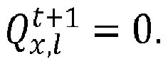

- In the
next step 303, the desired common capacity ratio is determined such that a maximum fairness is achieved for the estimated amount of flows. To this end, a utility function Φ may be defined that is to be maximized and which depends on the amount of flows Nd,l,Nu,l and the common capacity ratio Rcom :
- For example, when applying this to a synchronous time-division multiplexing access network where a TDD frame consists out of 35 DMT symbols, the following utility function may be defined:

- α is a positive parameter indicative for the shape of the utility function Φ and may be selected freely depending on the use case;
- wx,l is a positive weighting factor and may be selected freely depending on the use case;
- Mds defines the amount of DMT symbols allocated to vectored downstream transmission versus the amount of DMT symbols allocated to vectored upstream transmission, i.e., the DMT symbols with an index smaller than or equal to the Mds value are used for downstream transmission, while the others are used for upstream transmission; Mds is thus a specific measure of the common capacity ratio for the synchronous TDD application.
- This utility Φ is maximized for


- Optionally, an additional restriction may be applied by forcing that the common capacity ratio has to lie between certain bounds [Mdsmin,Mdsmax ]. In such a case, the capacity ratio may be obtained as:

- By the above equations Eq. 6 to Eq. 8 the Mds value that maximizes fairness among the amount of expected flows may be obtained, i.e., the desired common capacity ratio

-
Fig. 4 illustrates, according to an embodiment, further steps performed for configuring the communication system ofFig. 1 based on the determined desired common capacity
Fig. 3 . When performing the step according toFig. 4 , the communication system ofFig. 1 comprisesindependent AQM controllers - The
first steps communication controller 101 wherein the first step corresponds to the determination of the desired common capacity ratio
interval t + 1. In thenext step 402, thecommunication controller 101 configures thecommunication lines baseband controller 102.Baseband controller 102 then derives for each communication link the upstream and downstream capacities


physical layer logic subscriber equipments - Because of the adapted capacities of the communication links, the throughput on the communication links will change, and, consequently, the upstream and downstream queue occupancies


AQM controllers steps 


- In other words, the dynamic allocation of the capacities in
step 403 according to the desired common capacity ration acts as a master control for achieving a fair allocation of the capacities to the different traffic flows. The independent AQM controllers than depend on this master control and will follow accordingly by determining the AQM probabilities such that the fair allocation of the ingress rates to the different traffic flows is actually achieved. -
Fig. 5 illustrates, according to an alternative embodiment, further steps performed for configuring the communication system ofFig. 1 based on the determined desired common capacity
Fig. 3 . In this case, the communication system ofFig. 1 comprises a joint AQM controller, i.e., theupstream AQM controllers downstream AQM controllers 


Fig. 1 by the dashedline 113, 133 representing the joint operation of the AQM controllers. InFig. 5 the joint AQM controllers forrespective communication lines respective references 111+121 and 131+141 thereby indicating the joint operation ofrespective AQM controller - The joint AQM controllers determine the joint AQM probability
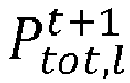
step 503, from both the queue occupancies


step 504 from the join AQM probability as:

- The ratio yl for a communication link is determined in a
step 502 from the desired common capacity ratio


- In other words, the ratio yl may be determined from Mdsb or, for the more general case, from
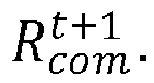
steps 501 to 504, the joint AQM controllers act as a master controller for achieving the fair apportionment of the upstream and downstream ingress rates according to the estimated amount of traffic flow. The actual capacities for the communication lines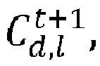

baseband controller 102 according to the observed ingress rates as controlled by the joint AQM controllers as shown insteps 505. In other words, the desired common capacity ratio is not directly applied to determine the actual capacities of the communication links. Instead, the desired common capacity ratio is used to determine the joint AQM probability for the joint AQM controller. The capacities

steps - Determining the


WO2017102683(A1 ). These methods accommodate the ingress rates as follows. As long as the sum of the expected downstream and upstream ingress rates


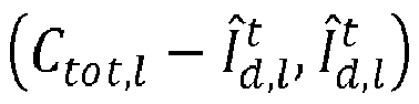

- The above utility function of equation (Eq. 5) introduced a shape parameter α and weighting factors wx,l . Below, these parameters and factors are discussed in more detail to show how they influence the characteristics of the working point.
- If α → 1, Eq. 6 reduces to


if α → ∞, Eq. 6 reduces to
- In this case wx,l = 1 for x ∈ {d,u} and l = 1, 2, ..., L. While for α → 1, the weighted sum of flow throughputs is maximized, for α → ∞ the minimum per-flow throughput considering some weights is maximized. For values of α between those values, there is a trade-off between those two. For the case that the total available capacity on the links is (C tot,1,C tot,2,Ctot,3 ) = (5.4,5.8,6.2)x100Mbps and the number of flows on the links are (N d,1,N d,2,N d,3) = (4,7,6) and (N u,1,N u,2,N u,3) = (10,8,2), Table 1 below illustrates the corresponding per-flow rates in units of 100Mbps.
Table 1 α Downstream flow rate Upstream flow rate Link 1 Link 2 Link 3 Link 1Link 2 Link 3 Minimum flow rate 0.01 0.6952 0.4267 0.5321 0.2619 0.3517 1.5037 0.2619 1 0.6203 0.3807 0.4748 0.2919 0.3919 1.6757 0.2919 2 0.5808 0.3565 0.4446 0.3077 0.4131 1.7663 0.3077 10 0.5370 0.3296 0.4110 0.3252 0.4366 1.8669 0.3252 100 0.5329 0.3271 0.4079 0.3268 0.4388 1.8763 0.3268 - In this case wx,l = 1/Nx,l for x ∈ {d,u} and l = 1, 2, ..., L. While for α → 1, all links are split half for downstream and half for upstream, for α → ∞ the minimum per-flow throughput is maximized. For values of α between those values, there is a trade-off between those two. For the case that the total available capacity on the links is (C tot,1, C tot,2, Ctot,3 ) = (5.4,5.8, 6.2)x100Mbps and the number of flows on the links are (N d,1,N d,2,N d,3) = (4,7,6) and (N u,1,N u,2, N u,3) = (10,8,2), Table 2 below illustrates the corresponding per-flow rates in units of 100Mbps..
Table 2 α Downstream flow rate Upstream flow rate Link 1 Link 2 Link 3 Link 1Link 2 Link 3 Minimum flow rate 1 0.6750 0.4143 0.5167 0.2700 0.3625 1.5500 0.2700 2 0.6416 0.3938 0.4911 0.2834 0.3804 1.6267 0.2834 10 0.5489 0.3369 0.4201 0.3205 0.4302 1.8397 0.3205 100 0.5341 0.3278 0.4088 0.3264 0.4382 1.8737 0.3264 - In this case wd,l = θ/Nd,l and wu,l = 1/Nu,l for l = 1, 2, ..., L, with θ ∈ [0,1], wherein, in a particular direction, the weights are still inversely proportional to the amount of flows. While for α → 1, all links are split with a downstream to upstream ratio equal to θ, for α → ∞ the minimum per-flow throughput is maximized. For values of α between those values, there is a trade-off between those two. For the case that the total available capacity on the links is (C tot,1, C tot,2, Ctot,3 ) = (5.4,5.8,6.2)x100Mbps and the number of flows on the links are (N d,1,N d,2,N d,3) = (4,7,6) and (N u,1,N u,2,N u,3) = (10,8,2), and θ = 4. Table 3 below illustrates the corresponding per-flow rates in units of 100Mbps.
Table 3 α DS flow rate US flow rate Link 1 Link 2 Link 3 Link 1Link 2 Link 3 Min flow rate 1 1.0800 0.6629 0.8267 0.1080 0.1450 0.6200 0.1080 2 0.8698 0.5339 0.6658 0.1921 0.2579 1.1026 0.1921 10 0.5945 0.3649 0.4551 0.3022 0.4057 1.7348 0.3022 100 0.5385 0.3305 0.4122 0.3246 0.4358 1.8634 0.3246 - From the above examples it may be observed that the working point associated with setting α very large is best in terms of avoiding starvation. No matter how the weights are chosen, it maximizes the minimum throughput allocated to the flows. The working point associated with setting the weights inversely proportional to the amount of flows and diversified in downstream and upstream wd,l = θ/Nd,l and wu,l = 1/Nu,l and for l = 1, 2, ..., L, with θ ∈ [0,1] and α → 1 is the case wherein rates are configured according to default downstream and upstream link rates. Hence, if the weights are set inversely proportional to the amount of flows and diversified in downstream and upstream with a parameter θ, the choice of the parameter α, allows to tune from a working point that maximizes the minimum flow rate fairness to a working point that is comparable to a fixed default Mds value.
-
Fig. 6 shows asuitable computing system 600 according to an example embodiment.Computing system 600 comprises means for performing the steps according to the above example embodiments.Computing system 600 may therefore be used as suitable implementation ofcontroller Computing system 600 may in general be formed as a suitable general-purpose computer and comprise abus 610, aprocessor 602, alocal memory 604, acommunication interface 612,storage element interface 606 and one ormore storage elements 608.Bus 610 may comprise one or more conductors that permit communication among the components of thecomputing system 600.Processor 602 may include any type of conventional processor or microprocessor that interprets and executes programming instructions.Local memory 604 may include a random-access memory (RAM) or another type of dynamic storage device that stores information and instructions for execution byprocessor 602 and/or a read only memory (ROM) or another type of static storage device that stores static information and instructions for use byprocessor 602.Input interface 614 may comprise one or more conventional mechanisms that permit an operator to input information to thecomputing device 600, such as akeyboard 620, amouse 630, a pen, voice recognition and/or biometric mechanisms, etc.Output interface 616 may comprise one or more conventional mechanisms that output information to the operator, such as a display 640, etc.Communication interface 612 may comprise any transceiver-like mechanism such as for example one or more Ethernet interfaces that enablescomputing system 600 to communicate with other devices and/or systems. Thecommunication interface 612 ofcomputing system 600 may be connected to such another computing system by means of a local area network (LAN) or a wide area network (WAN) such as for example the internet.Storage element interface 606 may comprise a storage interface such as for example a Serial Advanced Technology Attachment (SATA) interface or a Small Computer System Interface (SCSI) for connectingbus 610 to one ormore storage elements 608, such as one or more local disks, for example SATA disk drives, and control the reading and writing of data to and/or from thesestorage elements 608. Although thestorage elements 608 above is described as a local disk, in general any other suitable computer-readable media such as a removable magnetic disk, optical storage media such as a CD or DVD, -ROM disk, solid state drives, flash memory cards, ... may be used. - Although the present invention has been illustrated by reference to specific embodiments, it will be apparent to those skilled in the art that the invention is not limited to the details of the foregoing example embodiments, and that the present invention may be embodied with various changes and modifications without departing from the scope thereof. The present embodiments are therefore to be considered in all respects as illustrative and not restrictive, the scope of the invention being indicated by the appended claims rather than by the foregoing description, and all changes which come within the scope of the claims are therefore intended to be embraced therein.
- It will furthermore be understood by the reader of this patent application that the words "comprising" or "comprise" do not exclude other elements or steps, that the words "a" or "an" do not exclude a plurality, and that a single element, such as a computer system, a processor, or another integrated unit may fulfil the functions of several means recited in the claims. Any reference signs in the claims shall not be construed as limiting the respective claims concerned. The terms "first", "second", third", "a", "b", "c", and the like, when used in the description or in the claims are introduced to distinguish between similar elements or steps and are not necessarily describing a sequential or chronological order. Similarly, the terms "top", "bottom", "over", "under", and the like are introduced for descriptive purposes and not necessarily to denote relative positions. It is to be understood that the terms so used are interchangeable under appropriate circumstances and embodiments of the invention are capable of operating according to the present invention in other sequences, or in orientations different from the one(s) described or illustrated above.
Claims (13)
- A communication controller (101) comprising means for performing:- estimating (302) expected amounts of upstream and downstream traffic flows

 - determining (303), based on the expected amounts of upstream and downstream traffic flows


- The communication controller (101) according to claim 1 wherein the estimating (302) the expected amounts of upstream and downstream traffic flows
 - obtaining (304) active queue management, AQM, probabilities
 - deriving (302) the expected amounts of upstream and downstream traffic flows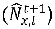

- The communication controller (101) according to claim 2 wherein the estimating (302) the expected amounts of upstream and downstream traffic flows
 - obtaining (305) a change in upstream and downstream queue occupancies

 - estimating (301) the upstream and downstream traffic ingress rates
- The communication controller (101) according to any one of the preceding claims further comprising means for performing:- configuring (403) the configurable upstream and downstream capacities


- A communication equipment (100) comprising the communication controller (101) according to claim 4, and comprising AQM controllers (111, 121, 131, 141) comprising means for performing active queue management, AQM, by determining independently upstream and downstream AQM probabilities for the communication links.
- The communication equipment (100) according to claim 5 wherein the communication controller (101) further comprises means for providing the configured upstream and downstream capacities

- The communication controller (101) according to any one of claims 1 to 3 further comprising means for providing joint AQM controllers (111+121, 131+141) with the desired common capacity ratio
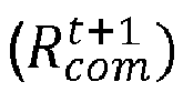


- Communication equipment (100) comprising:- the communication controller according to claim 7; and- the joint AQM controllers (111, 131) for performing active queue management, AQM,and wherein the joint AQM controller further comprises means for performing:- determining (503) the total AQM probability
 - determining (504) the upstream and downstream AQM probability


- The communication equipment (100) according to claim 8 wherein the joint AQM controller further comprises means for performing the apportioning (502) based on the desired common capacity ratio

- The communication equipment (100) according to any one of claims 8 or 9 comprising a physical layer controller (102) for configuring communication interfaces of the respective communication lines, the physical layer controller further comprising means for:- determining (505) an actual common capacity ratio
 - configuring (506) the configurable upstream and downstream capacities

- The communication controller (101) or communication equipment (100) according to any one of the preceding claims wherein the communication links (112, 132) comprise vectored communication lines and the capacity ratio is indicative for an allocation of DMT symbols between downstream and upstream transmission during an upcoming time frame.
- The communication controller (101) or communication equipment (100) according to any one of the preceding claims wherein the communication controller (101), the AQM controllers (111, 112, 113, 114), and/or the physical layer controller (102) comprises at least one processor and at least one memory including computer program code, the at least one memory and computer program code configured to, with the at least one processor, cause the performance of the respective communication controller, AQM controllers, and/or physical layer controller.
- A method comprising:- estimating (302) expected amounts of upstream and downstream traffic flows
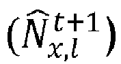
 - determining (303), based on the expected amounts of upstream and downstream traffic flows


Priority Applications (1)
| Application Number | Priority Date | Filing Date | Title |
|---|---|---|---|
| EP18178048.7A EP3582438B1 (en) | 2018-06-15 | 2018-06-15 | Common capacity ratio for a plurality of communication links |
Applications Claiming Priority (1)
| Application Number | Priority Date | Filing Date | Title |
|---|---|---|---|
| EP18178048.7A EP3582438B1 (en) | 2018-06-15 | 2018-06-15 | Common capacity ratio for a plurality of communication links |
Publications (2)
| Publication Number | Publication Date |
|---|---|
| EP3582438A1 true EP3582438A1 (en) | 2019-12-18 |
| EP3582438B1 EP3582438B1 (en) | 2024-02-07 |
Family
ID=62684717
Family Applications (1)
| Application Number | Title | Priority Date | Filing Date |
|---|---|---|---|
| EP18178048.7A Active EP3582438B1 (en) | 2018-06-15 | 2018-06-15 | Common capacity ratio for a plurality of communication links |
Country Status (1)
| Country | Link |
|---|---|
| EP (1) | EP3582438B1 (en) |
Citations (2)
| Publication number | Priority date | Publication date | Assignee | Title |
|---|---|---|---|---|
| US20080267068A1 (en) * | 2007-04-30 | 2008-10-30 | Lakshman Tirunell V | Lightweight bandwidth-management scheme for elastic traffic |
| WO2017102683A1 (en) | 2015-12-17 | 2017-06-22 | Alcatel Lucent | Apparatus and method for controlling tdd communications |
-
2018
- 2018-06-15 EP EP18178048.7A patent/EP3582438B1/en active Active
Patent Citations (2)
| Publication number | Priority date | Publication date | Assignee | Title |
|---|---|---|---|---|
| US20080267068A1 (en) * | 2007-04-30 | 2008-10-30 | Lakshman Tirunell V | Lightweight bandwidth-management scheme for elastic traffic |
| WO2017102683A1 (en) | 2015-12-17 | 2017-06-22 | Alcatel Lucent | Apparatus and method for controlling tdd communications |
Non-Patent Citations (2)
| Title |
|---|
| M. KUIPERS: "G.fast: Additional cDTA Emulation Results", ITU SG15 REPORT, SG15-C.392, June 2017 (2017-06-01) |
| M. KUIPERS: "G.fast: cDTA Emulation Results", ITU SG15 REPORT, Q4/15-C16 (170403, April 2017 (2017-04-01) |
Also Published As
| Publication number | Publication date |
|---|---|
| EP3582438B1 (en) | 2024-02-07 |
Similar Documents
| Publication | Publication Date | Title |
|---|---|---|
| JP4174052B2 (en) | Flow control in network devices | |
| Keshav | Packet-pair flow control | |
| JP4032231B2 (en) | Data transmission method | |
| EP4080829B1 (en) | Service class adjustment method, apparatus, device and storage medium | |
| DE602004011347T2 (en) | Sequence control and method for planning data transmission in a communication network | |
| US9762491B2 (en) | Dynamic thresholds for congestion control | |
| EP4054134A1 (en) | Congestion control method and releated device | |
| EP2491687B1 (en) | Aggregate policing applying max-min fairness for each data source based on probabilistic filtering | |
| CN113825171A (en) | Network congestion control method, device, equipment and medium | |
| US7430172B2 (en) | Method for allocating transmission bandwidth in a packet-oriented communications facility | |
| US20020039349A1 (en) | Telecommunications traffic regulator | |
| EP3200494A1 (en) | Radio resource allocation method and radio network controller | |
| US6704312B1 (en) | Switching apparatus and method using bandwidth decomposition | |
| Welzl | Scalable performance signalling and congestion avoidance | |
| EP3442182B1 (en) | Joint dropping or marking of data packets for traffic congestion control | |
| EP2220568B1 (en) | Methods and systems for providing efficient provisioning of data flows | |
| EP3582438B1 (en) | Common capacity ratio for a plurality of communication links | |
| CN116527587A (en) | System and method for realizing weight distribution of bandwidth based on AIMD | |
| Lee et al. | Enhanced TFRC for high quality video streaming over high bandwidth delay product networks | |
| Barrera et al. | Statistical detection of congestion in routers | |
| EP3270625B1 (en) | Managing medium access of an access point and associated devices in a wireless network | |
| EP1661334B1 (en) | Call admission control system and method for interpreting signaling messages and controlling traffic load in internet protocol differentiated services networks | |
| US7490163B2 (en) | Data unit transmission method and device | |
| US20070086483A1 (en) | Method and system for policing binary flows in a switching device | |
| EP3516858B1 (en) | Allocation of physical communication resources |
Legal Events
| Date | Code | Title | Description |
|---|---|---|---|
| PUAI | Public reference made under article 153(3) epc to a published international application that has entered the european phase |
Free format text: ORIGINAL CODE: 0009012 |
|
| STAA | Information on the status of an ep patent application or granted ep patent |
Free format text: STATUS: THE APPLICATION HAS BEEN PUBLISHED |
|
| AK | Designated contracting states |
Kind code of ref document: A1 Designated state(s): AL AT BE BG CH CY CZ DE DK EE ES FI FR GB GR HR HU IE IS IT LI LT LU LV MC MK MT NL NO PL PT RO RS SE SI SK SM TR |
|
| AX | Request for extension of the european patent |
Extension state: BA ME |
|
| STAA | Information on the status of an ep patent application or granted ep patent |
Free format text: STATUS: REQUEST FOR EXAMINATION WAS MADE |
|
| 17P | Request for examination filed |
Effective date: 20200618 |
|
| RBV | Designated contracting states (corrected) |
Designated state(s): AL AT BE BG CH CY CZ DE DK EE ES FI FR GB GR HR HU IE IS IT LI LT LU LV MC MK MT NL NO PL PT RO RS SE SI SK SM TR |
|
| STAA | Information on the status of an ep patent application or granted ep patent |
Free format text: STATUS: EXAMINATION IS IN PROGRESS |
|
| 17Q | First examination report despatched |
Effective date: 20201106 |
|
| REG | Reference to a national code |
Ref country code: DE Ipc: H04L0041089600 Ref legal event code: R079 Ref document number: 602018064889 Country of ref document: DE Free format text: PREVIOUS MAIN CLASS: H04L0012240000 |
|
| GRAP | Despatch of communication of intention to grant a patent |
Free format text: ORIGINAL CODE: EPIDOSNIGR1 |
|
| STAA | Information on the status of an ep patent application or granted ep patent |
Free format text: STATUS: GRANT OF PATENT IS INTENDED |
|
| RIC1 | Information provided on ipc code assigned before grant |
Ipc: H04L 47/41 20220101ALN20221026BHEP Ipc: H04L 43/0864 20220101ALN20221026BHEP Ipc: H04L 47/125 20220101ALI20221026BHEP Ipc: H04L 43/0894 20220101ALI20221026BHEP Ipc: H04L 41/0896 20220101AFI20221026BHEP |
|
| INTG | Intention to grant announced |
Effective date: 20221110 |
|
| GRAJ | Information related to disapproval of communication of intention to grant by the applicant or resumption of examination proceedings by the epo deleted |
Free format text: ORIGINAL CODE: EPIDOSDIGR1 |
|
| STAA | Information on the status of an ep patent application or granted ep patent |
Free format text: STATUS: EXAMINATION IS IN PROGRESS |
|
| GRAP | Despatch of communication of intention to grant a patent |
Free format text: ORIGINAL CODE: EPIDOSNIGR1 |
|
| STAA | Information on the status of an ep patent application or granted ep patent |
Free format text: STATUS: GRANT OF PATENT IS INTENDED |
|
| INTC | Intention to grant announced (deleted) | ||
| RIC1 | Information provided on ipc code assigned before grant |
Ipc: H04L 47/41 20220101ALN20230330BHEP Ipc: H04L 43/0864 20220101ALN20230330BHEP Ipc: H04L 47/125 20220101ALI20230330BHEP Ipc: H04L 43/0894 20220101ALI20230330BHEP Ipc: H04L 41/0896 20220101AFI20230330BHEP |
|
| INTG | Intention to grant announced |
Effective date: 20230412 |
|
| RIC1 | Information provided on ipc code assigned before grant |
Ipc: H04L 47/41 20220101ALN20230331BHEP Ipc: H04L 43/0864 20220101ALN20230331BHEP Ipc: H04L 47/125 20220101ALI20230331BHEP Ipc: H04L 43/0894 20220101ALI20230331BHEP Ipc: H04L 41/0896 20220101AFI20230331BHEP |
|
| GRAJ | Information related to disapproval of communication of intention to grant by the applicant or resumption of examination proceedings by the epo deleted |
Free format text: ORIGINAL CODE: EPIDOSDIGR1 |
|
| STAA | Information on the status of an ep patent application or granted ep patent |
Free format text: STATUS: EXAMINATION IS IN PROGRESS |
|
| GRAP | Despatch of communication of intention to grant a patent |
Free format text: ORIGINAL CODE: EPIDOSNIGR1 |
|
| STAA | Information on the status of an ep patent application or granted ep patent |
Free format text: STATUS: GRANT OF PATENT IS INTENDED |
|
| INTC | Intention to grant announced (deleted) | ||
| RIC1 | Information provided on ipc code assigned before grant |
Ipc: H04L 47/41 20220101ALN20230906BHEP Ipc: H04L 43/0864 20220101ALN20230906BHEP Ipc: H04L 47/125 20220101ALI20230906BHEP Ipc: H04L 43/0894 20220101ALI20230906BHEP Ipc: H04L 41/0896 20220101AFI20230906BHEP |
|
| INTG | Intention to grant announced |
Effective date: 20230919 |
|
| GRAS | Grant fee paid |
Free format text: ORIGINAL CODE: EPIDOSNIGR3 |
|
| GRAA | (expected) grant |
Free format text: ORIGINAL CODE: 0009210 |
|
| STAA | Information on the status of an ep patent application or granted ep patent |
Free format text: STATUS: THE PATENT HAS BEEN GRANTED |
|
| AK | Designated contracting states |
Kind code of ref document: B1 Designated state(s): AL AT BE BG CH CY CZ DE DK EE ES FI FR GB GR HR HU IE IS IT LI LT LU LV MC MK MT NL NO PL PT RO RS SE SI SK SM TR |
|
| REG | Reference to a national code |
Ref country code: GB Ref legal event code: FG4D |
|
| REG | Reference to a national code |
Ref country code: CH Ref legal event code: EP |
|
| REG | Reference to a national code |
Ref country code: IE Ref legal event code: FG4D |
|
| REG | Reference to a national code |
Ref country code: DE Ref legal event code: R096 Ref document number: 602018064889 Country of ref document: DE |
|
| REG | Reference to a national code |
Ref country code: LT Ref legal event code: MG9D |
|
| REG | Reference to a national code |
Ref country code: NL Ref legal event code: MP Effective date: 20240207 |
|
| PG25 | Lapsed in a contracting state [announced via postgrant information from national office to epo] |
Ref country code: IS Free format text: LAPSE BECAUSE OF FAILURE TO SUBMIT A TRANSLATION OF THE DESCRIPTION OR TO PAY THE FEE WITHIN THE PRESCRIBED TIME-LIMIT Effective date: 20240607 |
|
| PG25 | Lapsed in a contracting state [announced via postgrant information from national office to epo] |
Ref country code: LT Free format text: LAPSE BECAUSE OF FAILURE TO SUBMIT A TRANSLATION OF THE DESCRIPTION OR TO PAY THE FEE WITHIN THE PRESCRIBED TIME-LIMIT Effective date: 20240207 |
|
| PG25 | Lapsed in a contracting state [announced via postgrant information from national office to epo] |
Ref country code: GR Free format text: LAPSE BECAUSE OF FAILURE TO SUBMIT A TRANSLATION OF THE DESCRIPTION OR TO PAY THE FEE WITHIN THE PRESCRIBED TIME-LIMIT Effective date: 20240508 |
|
| REG | Reference to a national code |
Ref country code: AT Ref legal event code: MK05 Ref document number: 1656078 Country of ref document: AT Kind code of ref document: T Effective date: 20240207 |
|
| PG25 | Lapsed in a contracting state [announced via postgrant information from national office to epo] |
Ref country code: NL Free format text: LAPSE BECAUSE OF FAILURE TO SUBMIT A TRANSLATION OF THE DESCRIPTION OR TO PAY THE FEE WITHIN THE PRESCRIBED TIME-LIMIT Effective date: 20240207 Ref country code: HR Free format text: LAPSE BECAUSE OF FAILURE TO SUBMIT A TRANSLATION OF THE DESCRIPTION OR TO PAY THE FEE WITHIN THE PRESCRIBED TIME-LIMIT Effective date: 20240207 Ref country code: RS Free format text: LAPSE BECAUSE OF FAILURE TO SUBMIT A TRANSLATION OF THE DESCRIPTION OR TO PAY THE FEE WITHIN THE PRESCRIBED TIME-LIMIT Effective date: 20240507 |
|
| PG25 | Lapsed in a contracting state [announced via postgrant information from national office to epo] |
Ref country code: ES Free format text: LAPSE BECAUSE OF FAILURE TO SUBMIT A TRANSLATION OF THE DESCRIPTION OR TO PAY THE FEE WITHIN THE PRESCRIBED TIME-LIMIT Effective date: 20240207 |
|
| PG25 | Lapsed in a contracting state [announced via postgrant information from national office to epo] |
Ref country code: AT Free format text: LAPSE BECAUSE OF FAILURE TO SUBMIT A TRANSLATION OF THE DESCRIPTION OR TO PAY THE FEE WITHIN THE PRESCRIBED TIME-LIMIT Effective date: 20240207 |
|
| PG25 | Lapsed in a contracting state [announced via postgrant information from national office to epo] |
Ref country code: RS Free format text: LAPSE BECAUSE OF FAILURE TO SUBMIT A TRANSLATION OF THE DESCRIPTION OR TO PAY THE FEE WITHIN THE PRESCRIBED TIME-LIMIT Effective date: 20240507 Ref country code: NO Free format text: LAPSE BECAUSE OF FAILURE TO SUBMIT A TRANSLATION OF THE DESCRIPTION OR TO PAY THE FEE WITHIN THE PRESCRIBED TIME-LIMIT Effective date: 20240507 Ref country code: NL Free format text: LAPSE BECAUSE OF FAILURE TO SUBMIT A TRANSLATION OF THE DESCRIPTION OR TO PAY THE FEE WITHIN THE PRESCRIBED TIME-LIMIT Effective date: 20240207 Ref country code: LT Free format text: LAPSE BECAUSE OF FAILURE TO SUBMIT A TRANSLATION OF THE DESCRIPTION OR TO PAY THE FEE WITHIN THE PRESCRIBED TIME-LIMIT Effective date: 20240207 Ref country code: IS Free format text: LAPSE BECAUSE OF FAILURE TO SUBMIT A TRANSLATION OF THE DESCRIPTION OR TO PAY THE FEE WITHIN THE PRESCRIBED TIME-LIMIT Effective date: 20240607 Ref country code: HR Free format text: LAPSE BECAUSE OF FAILURE TO SUBMIT A TRANSLATION OF THE DESCRIPTION OR TO PAY THE FEE WITHIN THE PRESCRIBED TIME-LIMIT Effective date: 20240207 Ref country code: GR Free format text: LAPSE BECAUSE OF FAILURE TO SUBMIT A TRANSLATION OF THE DESCRIPTION OR TO PAY THE FEE WITHIN THE PRESCRIBED TIME-LIMIT Effective date: 20240508 Ref country code: FI Free format text: LAPSE BECAUSE OF FAILURE TO SUBMIT A TRANSLATION OF THE DESCRIPTION OR TO PAY THE FEE WITHIN THE PRESCRIBED TIME-LIMIT Effective date: 20240207 Ref country code: ES Free format text: LAPSE BECAUSE OF FAILURE TO SUBMIT A TRANSLATION OF THE DESCRIPTION OR TO PAY THE FEE WITHIN THE PRESCRIBED TIME-LIMIT Effective date: 20240207 Ref country code: BG Free format text: LAPSE BECAUSE OF FAILURE TO SUBMIT A TRANSLATION OF THE DESCRIPTION OR TO PAY THE FEE WITHIN THE PRESCRIBED TIME-LIMIT Effective date: 20240207 Ref country code: AT Free format text: LAPSE BECAUSE OF FAILURE TO SUBMIT A TRANSLATION OF THE DESCRIPTION OR TO PAY THE FEE WITHIN THE PRESCRIBED TIME-LIMIT Effective date: 20240207 |
|
| PG25 | Lapsed in a contracting state [announced via postgrant information from national office to epo] |
Ref country code: PL Free format text: LAPSE BECAUSE OF FAILURE TO SUBMIT A TRANSLATION OF THE DESCRIPTION OR TO PAY THE FEE WITHIN THE PRESCRIBED TIME-LIMIT Effective date: 20240207 Ref country code: PT Free format text: LAPSE BECAUSE OF FAILURE TO SUBMIT A TRANSLATION OF THE DESCRIPTION OR TO PAY THE FEE WITHIN THE PRESCRIBED TIME-LIMIT Effective date: 20240607 |
|
| PG25 | Lapsed in a contracting state [announced via postgrant information from national office to epo] |
Ref country code: SE Free format text: LAPSE BECAUSE OF FAILURE TO SUBMIT A TRANSLATION OF THE DESCRIPTION OR TO PAY THE FEE WITHIN THE PRESCRIBED TIME-LIMIT Effective date: 20240207 Ref country code: PT Free format text: LAPSE BECAUSE OF FAILURE TO SUBMIT A TRANSLATION OF THE DESCRIPTION OR TO PAY THE FEE WITHIN THE PRESCRIBED TIME-LIMIT Effective date: 20240607 Ref country code: PL Free format text: LAPSE BECAUSE OF FAILURE TO SUBMIT A TRANSLATION OF THE DESCRIPTION OR TO PAY THE FEE WITHIN THE PRESCRIBED TIME-LIMIT Effective date: 20240207 Ref country code: LV Free format text: LAPSE BECAUSE OF FAILURE TO SUBMIT A TRANSLATION OF THE DESCRIPTION OR TO PAY THE FEE WITHIN THE PRESCRIBED TIME-LIMIT Effective date: 20240207 |
|
| PG25 | Lapsed in a contracting state [announced via postgrant information from national office to epo] |
Ref country code: DK Free format text: LAPSE BECAUSE OF FAILURE TO SUBMIT A TRANSLATION OF THE DESCRIPTION OR TO PAY THE FEE WITHIN THE PRESCRIBED TIME-LIMIT Effective date: 20240207 |
|
| PG25 | Lapsed in a contracting state [announced via postgrant information from national office to epo] |
Ref country code: SM Free format text: LAPSE BECAUSE OF FAILURE TO SUBMIT A TRANSLATION OF THE DESCRIPTION OR TO PAY THE FEE WITHIN THE PRESCRIBED TIME-LIMIT Effective date: 20240207 |
|
| PG25 | Lapsed in a contracting state [announced via postgrant information from national office to epo] |
Ref country code: CZ Free format text: LAPSE BECAUSE OF FAILURE TO SUBMIT A TRANSLATION OF THE DESCRIPTION OR TO PAY THE FEE WITHIN THE PRESCRIBED TIME-LIMIT Effective date: 20240207 Ref country code: EE Free format text: LAPSE BECAUSE OF FAILURE TO SUBMIT A TRANSLATION OF THE DESCRIPTION OR TO PAY THE FEE WITHIN THE PRESCRIBED TIME-LIMIT Effective date: 20240207 |
|
| PG25 | Lapsed in a contracting state [announced via postgrant information from national office to epo] |
Ref country code: SK Free format text: LAPSE BECAUSE OF FAILURE TO SUBMIT A TRANSLATION OF THE DESCRIPTION OR TO PAY THE FEE WITHIN THE PRESCRIBED TIME-LIMIT Effective date: 20240207 |
|
| PG25 | Lapsed in a contracting state [announced via postgrant information from national office to epo] |
Ref country code: SM Free format text: LAPSE BECAUSE OF FAILURE TO SUBMIT A TRANSLATION OF THE DESCRIPTION OR TO PAY THE FEE WITHIN THE PRESCRIBED TIME-LIMIT Effective date: 20240207 Ref country code: SK Free format text: LAPSE BECAUSE OF FAILURE TO SUBMIT A TRANSLATION OF THE DESCRIPTION OR TO PAY THE FEE WITHIN THE PRESCRIBED TIME-LIMIT Effective date: 20240207 Ref country code: RO Free format text: LAPSE BECAUSE OF FAILURE TO SUBMIT A TRANSLATION OF THE DESCRIPTION OR TO PAY THE FEE WITHIN THE PRESCRIBED TIME-LIMIT Effective date: 20240207 Ref country code: EE Free format text: LAPSE BECAUSE OF FAILURE TO SUBMIT A TRANSLATION OF THE DESCRIPTION OR TO PAY THE FEE WITHIN THE PRESCRIBED TIME-LIMIT Effective date: 20240207 Ref country code: DK Free format text: LAPSE BECAUSE OF FAILURE TO SUBMIT A TRANSLATION OF THE DESCRIPTION OR TO PAY THE FEE WITHIN THE PRESCRIBED TIME-LIMIT Effective date: 20240207 Ref country code: CZ Free format text: LAPSE BECAUSE OF FAILURE TO SUBMIT A TRANSLATION OF THE DESCRIPTION OR TO PAY THE FEE WITHIN THE PRESCRIBED TIME-LIMIT Effective date: 20240207 |
|
| REG | Reference to a national code |
Ref country code: DE Ref legal event code: R097 Ref document number: 602018064889 Country of ref document: DE |
|
| PG25 | Lapsed in a contracting state [announced via postgrant information from national office to epo] |
Ref country code: IT Free format text: LAPSE BECAUSE OF FAILURE TO SUBMIT A TRANSLATION OF THE DESCRIPTION OR TO PAY THE FEE WITHIN THE PRESCRIBED TIME-LIMIT Effective date: 20240207 |
|
| PLBE | No opposition filed within time limit |
Free format text: ORIGINAL CODE: 0009261 |
|
| STAA | Information on the status of an ep patent application or granted ep patent |
Free format text: STATUS: NO OPPOSITION FILED WITHIN TIME LIMIT |
|
| PG25 | Lapsed in a contracting state [announced via postgrant information from national office to epo] |
Ref country code: IT Free format text: LAPSE BECAUSE OF FAILURE TO SUBMIT A TRANSLATION OF THE DESCRIPTION OR TO PAY THE FEE WITHIN THE PRESCRIBED TIME-LIMIT Effective date: 20240207 |
|
| 26N | No opposition filed |
Effective date: 20241108 |
|
| PG25 | Lapsed in a contracting state [announced via postgrant information from national office to epo] |
Ref country code: MC Free format text: LAPSE BECAUSE OF FAILURE TO SUBMIT A TRANSLATION OF THE DESCRIPTION OR TO PAY THE FEE WITHIN THE PRESCRIBED TIME-LIMIT Effective date: 20240207 |
|
| REG | Reference to a national code |
Ref country code: CH Ref legal event code: PL |
|
| PG25 | Lapsed in a contracting state [announced via postgrant information from national office to epo] |
Ref country code: LU Free format text: LAPSE BECAUSE OF NON-PAYMENT OF DUE FEES Effective date: 20240615 |
|
| PG25 | Lapsed in a contracting state [announced via postgrant information from national office to epo] |
Ref country code: IE Free format text: LAPSE BECAUSE OF NON-PAYMENT OF DUE FEES Effective date: 20240615 |
|
| PG25 | Lapsed in a contracting state [announced via postgrant information from national office to epo] |
Ref country code: SI Free format text: LAPSE BECAUSE OF FAILURE TO SUBMIT A TRANSLATION OF THE DESCRIPTION OR TO PAY THE FEE WITHIN THE PRESCRIBED TIME-LIMIT Effective date: 20240207 Ref country code: BE Free format text: LAPSE BECAUSE OF NON-PAYMENT OF DUE FEES Effective date: 20240630 Ref country code: CH Free format text: LAPSE BECAUSE OF NON-PAYMENT OF DUE FEES Effective date: 20240630 |
|
| PG25 | Lapsed in a contracting state [announced via postgrant information from national office to epo] |
Ref country code: FR Free format text: LAPSE BECAUSE OF NON-PAYMENT OF DUE FEES Effective date: 20240630 |
|
| REG | Reference to a national code |
Ref country code: BE Ref legal event code: MM Effective date: 20240630 |
|
| PGFP | Annual fee paid to national office [announced via postgrant information from national office to epo] |
Ref country code: DE Payment date: 20250429 Year of fee payment: 8 |
|
| PGFP | Annual fee paid to national office [announced via postgrant information from national office to epo] |
Ref country code: GB Payment date: 20250501 Year of fee payment: 8 |
|
| PG25 | Lapsed in a contracting state [announced via postgrant information from national office to epo] |
Ref country code: CY Free format text: LAPSE BECAUSE OF FAILURE TO SUBMIT A TRANSLATION OF THE DESCRIPTION OR TO PAY THE FEE WITHIN THE PRESCRIBED TIME-LIMIT; INVALID AB INITIO Effective date: 20180615 |
|
| PG25 | Lapsed in a contracting state [announced via postgrant information from national office to epo] |
Ref country code: HU Free format text: LAPSE BECAUSE OF FAILURE TO SUBMIT A TRANSLATION OF THE DESCRIPTION OR TO PAY THE FEE WITHIN THE PRESCRIBED TIME-LIMIT; INVALID AB INITIO Effective date: 20180615 |