EP3582318A1 - Apparatus for allocating identification information to plurality of slave battery management units - Google Patents
Apparatus for allocating identification information to plurality of slave battery management units Download PDFInfo
- Publication number
- EP3582318A1 EP3582318A1 EP18859107.7A EP18859107A EP3582318A1 EP 3582318 A1 EP3582318 A1 EP 3582318A1 EP 18859107 A EP18859107 A EP 18859107A EP 3582318 A1 EP3582318 A1 EP 3582318A1
- Authority
- EP
- European Patent Office
- Prior art keywords
- battery management
- antenna
- identification information
- slave
- antennas
- Prior art date
- Legal status (The legal status is an assumption and is not a legal conclusion. Google has not performed a legal analysis and makes no representation as to the accuracy of the status listed.)
- Granted
Links
Images



Classifications
-
- H—ELECTRICITY
- H01—ELECTRIC ELEMENTS
- H01M—PROCESSES OR MEANS, e.g. BATTERIES, FOR THE DIRECT CONVERSION OF CHEMICAL ENERGY INTO ELECTRICAL ENERGY
- H01M10/00—Secondary cells; Manufacture thereof
- H01M10/42—Methods or arrangements for servicing or maintenance of secondary cells or secondary half-cells
- H01M10/4221—Methods or arrangements for servicing or maintenance of secondary cells or secondary half-cells with battery type recognition
-
- H—ELECTRICITY
- H01—ELECTRIC ELEMENTS
- H01M—PROCESSES OR MEANS, e.g. BATTERIES, FOR THE DIRECT CONVERSION OF CHEMICAL ENERGY INTO ELECTRICAL ENERGY
- H01M10/00—Secondary cells; Manufacture thereof
- H01M10/42—Methods or arrangements for servicing or maintenance of secondary cells or secondary half-cells
- H01M10/425—Structural combination with electronic components, e.g. electronic circuits integrated to the outside of the casing
- H01M10/4257—Smart batteries, e.g. electronic circuits inside the housing of the cells or batteries
-
- H—ELECTRICITY
- H01—ELECTRIC ELEMENTS
- H01M—PROCESSES OR MEANS, e.g. BATTERIES, FOR THE DIRECT CONVERSION OF CHEMICAL ENERGY INTO ELECTRICAL ENERGY
- H01M10/00—Secondary cells; Manufacture thereof
- H01M10/42—Methods or arrangements for servicing or maintenance of secondary cells or secondary half-cells
- H01M10/425—Structural combination with electronic components, e.g. electronic circuits integrated to the outside of the casing
-
- H—ELECTRICITY
- H01—ELECTRIC ELEMENTS
- H01M—PROCESSES OR MEANS, e.g. BATTERIES, FOR THE DIRECT CONVERSION OF CHEMICAL ENERGY INTO ELECTRICAL ENERGY
- H01M10/00—Secondary cells; Manufacture thereof
- H01M10/42—Methods or arrangements for servicing or maintenance of secondary cells or secondary half-cells
- H01M10/4207—Methods or arrangements for servicing or maintenance of secondary cells or secondary half-cells for several batteries or cells simultaneously or sequentially
-
- H—ELECTRICITY
- H01—ELECTRIC ELEMENTS
- H01M—PROCESSES OR MEANS, e.g. BATTERIES, FOR THE DIRECT CONVERSION OF CHEMICAL ENERGY INTO ELECTRICAL ENERGY
- H01M10/00—Secondary cells; Manufacture thereof
- H01M10/42—Methods or arrangements for servicing or maintenance of secondary cells or secondary half-cells
- H01M10/48—Accumulators combined with arrangements for measuring, testing or indicating the condition of cells, e.g. the level or density of the electrolyte
- H01M10/482—Accumulators combined with arrangements for measuring, testing or indicating the condition of cells, e.g. the level or density of the electrolyte for several batteries or cells simultaneously or sequentially
-
- H—ELECTRICITY
- H01—ELECTRIC ELEMENTS
- H01M—PROCESSES OR MEANS, e.g. BATTERIES, FOR THE DIRECT CONVERSION OF CHEMICAL ENERGY INTO ELECTRICAL ENERGY
- H01M50/00—Constructional details or processes of manufacture of the non-active parts of electrochemical cells other than fuel cells, e.g. hybrid cells
- H01M50/20—Mountings; Secondary casings or frames; Racks, modules or packs; Suspension devices; Shock absorbers; Transport or carrying devices; Holders
- H01M50/204—Racks, modules or packs for multiple batteries or multiple cells
-
- H—ELECTRICITY
- H01—ELECTRIC ELEMENTS
- H01M—PROCESSES OR MEANS, e.g. BATTERIES, FOR THE DIRECT CONVERSION OF CHEMICAL ENERGY INTO ELECTRICAL ENERGY
- H01M50/00—Constructional details or processes of manufacture of the non-active parts of electrochemical cells other than fuel cells, e.g. hybrid cells
- H01M50/20—Mountings; Secondary casings or frames; Racks, modules or packs; Suspension devices; Shock absorbers; Transport or carrying devices; Holders
- H01M50/271—Lids or covers for the racks or secondary casings
- H01M50/273—Lids or covers for the racks or secondary casings characterised by the material
- H01M50/276—Inorganic material
-
- H—ELECTRICITY
- H01—ELECTRIC ELEMENTS
- H01Q—ANTENNAS, i.e. RADIO AERIALS
- H01Q1/00—Details of, or arrangements associated with, antennas
- H01Q1/12—Supports; Mounting means
- H01Q1/22—Supports; Mounting means by structural association with other equipment or articles
-
- H—ELECTRICITY
- H01—ELECTRIC ELEMENTS
- H01Q—ANTENNAS, i.e. RADIO AERIALS
- H01Q17/00—Devices for absorbing waves radiated from an antenna; Combinations of such devices with active antenna elements or systems
-
- H—ELECTRICITY
- H01—ELECTRIC ELEMENTS
- H01M—PROCESSES OR MEANS, e.g. BATTERIES, FOR THE DIRECT CONVERSION OF CHEMICAL ENERGY INTO ELECTRICAL ENERGY
- H01M10/00—Secondary cells; Manufacture thereof
- H01M10/42—Methods or arrangements for servicing or maintenance of secondary cells or secondary half-cells
- H01M10/425—Structural combination with electronic components, e.g. electronic circuits integrated to the outside of the casing
- H01M2010/4271—Battery management systems including electronic circuits, e.g. control of current or voltage to keep battery in healthy state, cell balancing
-
- H—ELECTRICITY
- H01—ELECTRIC ELEMENTS
- H01M—PROCESSES OR MEANS, e.g. BATTERIES, FOR THE DIRECT CONVERSION OF CHEMICAL ENERGY INTO ELECTRICAL ENERGY
- H01M10/00—Secondary cells; Manufacture thereof
- H01M10/42—Methods or arrangements for servicing or maintenance of secondary cells or secondary half-cells
- H01M10/425—Structural combination with electronic components, e.g. electronic circuits integrated to the outside of the casing
- H01M2010/4278—Systems for data transfer from batteries, e.g. transfer of battery parameters to a controller, data transferred between battery controller and main controller
-
- H—ELECTRICITY
- H01—ELECTRIC ELEMENTS
- H01M—PROCESSES OR MEANS, e.g. BATTERIES, FOR THE DIRECT CONVERSION OF CHEMICAL ENERGY INTO ELECTRICAL ENERGY
- H01M2220/00—Batteries for particular applications
- H01M2220/20—Batteries in motive systems, e.g. vehicle, ship, plane
-
- Y—GENERAL TAGGING OF NEW TECHNOLOGICAL DEVELOPMENTS; GENERAL TAGGING OF CROSS-SECTIONAL TECHNOLOGIES SPANNING OVER SEVERAL SECTIONS OF THE IPC; TECHNICAL SUBJECTS COVERED BY FORMER USPC CROSS-REFERENCE ART COLLECTIONS [XRACs] AND DIGESTS
- Y02—TECHNOLOGIES OR APPLICATIONS FOR MITIGATION OR ADAPTATION AGAINST CLIMATE CHANGE
- Y02E—REDUCTION OF GREENHOUSE GAS [GHG] EMISSIONS, RELATED TO ENERGY GENERATION, TRANSMISSION OR DISTRIBUTION
- Y02E60/00—Enabling technologies; Technologies with a potential or indirect contribution to GHG emissions mitigation
- Y02E60/10—Energy storage using batteries
Definitions
- the present disclosure relates to an apparatus for assigning identification information to a plurality of slave battery management units mounted on a battery pack, and more particularly, to an apparatus for assigning different identification information to different slave battery management units by using a wireless signal before the assembly of a battery pack is completed.
- lithium secondary batteries have almost no memory effect as compared with nickel-based secondary batteries, and are thus free for charge and discharge and have a very low self-discharge rate and a high energy density. Due to these advantages, lithium secondary batteries have attracted attention.
- a battery pack applied to an electric vehicle or the like typically includes a plurality of battery modules and a plurality of slave battery management units connected in series and/or in parallel. Each of the slave battery management units monitors and controls the state of the battery module to be managed. Recently, as large-capacity and high-output battery packs are required, the number of battery modules included in the battery pack is also increasing.
- a multi-slave structure is disclosed.
- the multi-slave structure includes a plurality of slave battery management units installed in each battery module and a master battery management unit that controls the plurality of slave battery management units as a whole.
- each slave battery management unit in order for a master battery management unit to collect state information of a plurality of battery modules from a plurality of slave battery management units and transmit a control command for the plurality of battery modules to the plurality of slave battery management units, each slave battery management unit must be assigned an ID indicating a physical or electrical position of a battery module to be managed.
- Patent Literature 1 discloses a technique for sequentially assigning IDs to a plurality of slave battery management units. Patent Literature 1 proposes a method of assigning an ID in a state in which a master battery management unit is connected to each slave battery management unit by wire. However, in the ID assigning method according to Patent Literature 1, since it is assumed that the master battery management unit is connected to each slave battery management unit by wire, there are concerns such as disconnection of electric wires and space restriction is great. In addition, in order to set the IDs in the order of hardware positions of the respective slave battery management units, a process of measuring a potential difference by the batteries managed by each slave battery management unit must be preceded.
- a method by which the master battery management unit assigns identification information to a plurality of slave battery management units in a wireless scheme may be considered.
- the master battery management unit In order to assign identification information in a wireless scheme, the master battery management unit must precede a process of checking to which one of the plurality of battery modules included in the battery pack each slave battery management unit is electrically connected.
- module information for example, potential, voltage, temperature, or the like
- Patent Literature 1 Korean Patent Application Publication No. 10-2011-0013747 (published on February 10, 2011)
- the present disclosure is designed to solve the problems of the related art, and therefore the present disclosure is directed to providing an apparatus for assigning identification information to a plurality of slave battery management units (BMUs) mounted on a battery pack by using a wireless signal before the manufacturing of the battery pack is completed.
- BMUs slave battery management units
- the apparatus may include: a casing jig configured to at least partially cover the plurality of slave battery management units together with the base plate; a wireless communication unit including a plurality of antennas disposed in a region of the casing jig facing the base plate so as to correspond one-to-one to the plurality of slave battery management units; and a controller electrically connected to the wireless communication unit.
- the controller may be configured to select at least one of the plurality of antennas and transmit, to the wireless communication unit, a first control signal including identification information related to the at least one selected antenna.
- the wireless communication unit may be configured to output a wireless signal indicating the identification information through an antenna associated with the identification information in response to the first control signal.
- the controller may be further configured to select two or more of the plurality of antennas at the same time, or to select the plurality of antennas one by one in a predetermined order.
- the wireless signal may have signal strength in a predetermined range.
- the casing jig may include: a supporting member at least partially made of a metallic material and defining an overall appearance of the casing jig so that the plurality of antennas are disposed; and an electromagnetic wave absorbing member coupled to at least a part of an inner surface of the supporting member.
- the controller may include a memory in which a plurality of reference positions and a plurality of pieces of identification information mapped one-to-one to the plurality of reference positions are stored.
- the plurality of reference positions may indicate positions at which the plurality of antennas are disposed in the casing jig, respectively.
- the controller may be further configured to: select a first antenna and a second antenna among the plurality of antennas at the same time with reference to the plurality of reference positions prestored in the memory.
- a distance between a first reference position corresponding to the first antenna and a second reference position corresponding to the second antenna is equal to or greater than a predetermined threshold distance.
- the apparatus may further include a power supply unit configured to selectively supply operating power to at least one of the plurality of slave battery management units.
- the controller When transmitting the first control signal, the controller may be further configured to transmit, to the power supply unit, a second control signal related to the first control signal.
- the power supply unit may be further configured to supply the operating power to the slave battery management unit corresponding to the at least one selected antenna among the plurality of slave battery management units, in response to the second control signal.
- identification information may be assigned to each of the plurality of slave BMUs mounted on a battery pack by using a wireless signal. Therefore, identification information for each of the plurality of slave BMUs may be easily assigned without separate wired connection lines.
- identification information may be assigned to each of the plurality of slave BMUs before the manufacturing of the battery pack is completed.
- control unit as used herein, represent a unit for processing at least one function or operation, which may be implemented by hardware, software, or a combination thereof.
- FIG. 1 is a diagram schematically illustrating a state in which an identification information assigning apparatus 100 according to an embodiment of the present disclosure is separated from a base plate 11 of a battery pack 10
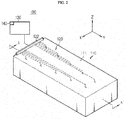
- FIG. 2 is a diagram schematically illustrating a state in which the identification information assigning apparatus 100 of FIG. 1 is coupled to the base plate 11 of the battery pack 10
- FIG. 3 is a cross-sectional view taken along line A-A' of FIG. 2 .
- the identification information assigning apparatus 100 assigns different identification information to a plurality of slave BMUs 30 mounted on the battery pack 10 before assembly is completed.
- the identification information may be, for example, a unique address used for wireless communication with a master BMU (not illustrated).
- the battery pack 10 is assembled by mounting a plurality of battery modules 20, the plurality of slave BMUs 30, and the master BMU on the base plate 11 and coupling a pack cover (not illustrated).
- the apparatus 100 is used to assign identification information to each of the plurality of slave BMUs 30 before the pack cover is coupled to the base plate 11.
- the plurality of slave BMUs 30-1 to 30-10 are electrically coupled one-to-one to the plurality of battery modules 20-1 to 20-10.
- Each of the slave BMUs 30 may be operated with operating power received from the battery module 20 or the apparatus 100 to which each of the slave BMU 30 is electrically connected.
- Each of the slave BMUs 30-1 to 30-10 includes at least one antenna 31 configured to collect wireless signals from the apparatus 100.
- the apparatus 100 may include a casing jig 110, a wireless communication unit 120, a controller 130, and a memory 140.
- the casing jig 110 is configured to at least partially cover the plurality of slave BMUs 30-1 to 30-10 together with the base plate 11.
- the casing jig 110 may have the equal or similar appearance to the pack cover (not illustrated) can be coupled to the base plate 11. It will be apparent that the shape and size of the casing jig 110 may be freely changed as needed.
- the casing jig 110 basically includes a supporting member 111 and optionally further includes an electromagnetic wave absorbing member 112.
- the supporting member 111 defines the overall appearance of the casing jig 110 so that a plurality of antennas 121-1 to 121-10 included in the wireless communication unit 120 may be disposed.
- at least a portion of the supporting member 111 may be made of a metallic material.
- the supporting member 111 may have a substrate 111a forming the upper surface of the casing jig 110 and a partition wall 111b forming the side surface, and the lower portion thereof may be opened so as to have a basket shape.
- the opened lower portion of the casing jig 110 is at least partly closed by the base plate 11.
- the plurality of battery modules 20-1 to 20-10, the plurality of slave battery management units 30-1 to 30-10, and the plurality of antennas 121-1 to 121-10 are accommodated in the inner space provided by the connection of the casing jig 110 and the base plate 11.
- the electromagnetic wave absorbing member 112 is coupled to at least a part of the inner surface of the supporting member 111.
- the electromagnetic wave absorbing member 112 suppresses noise caused by electromagnetic waves generated from the plurality of antennas 121-1 to 121-10 in the internal space provided by the connection of the casing jig 110 and the base plate 11.
- the wireless communication unit 120 includes the plurality of antennas 121-1 to 121-10 and a wireless communication circuit 122.
- the plurality of antennas 121-1 to 121-10 are spaced apart from each other so as to correspond one-to-one to the plurality of slave BMUs 30-1 to 30-10 in a region of the lower surfaces of both sides of the substrate opposite to the base plate 11. That is, when (2 ⁇ 5) ⁇ m ⁇ 1, the m-th antenna 121-m is disposed at a specific position of the casing jig 110 closer to the m-th slave BMU 30-m than the remaining antennas 121.
- the m-th antenna 121-m may be disposed within a reference distance from the m-th slave BMU 30-m and farther than the reference distance from the remaining slave BMUs 30.
- the wireless communication circuit 122 transmits a wireless signal to at least one of the plurality of slave BMUs 30-1 to 30-10 through at least one of the plurality of antennas 121-1 to 121-10 in response to a first control signal from the controller 130.
- the first control signal may include antenna selection information and identification information.
- the identification information included in the the first control signal is information to be assigned to the slave BMU 30-k corresponding to the antenna 121-k selected by the antenna selection information.
- the identification information included in the first control signal is modulated by the wireless communication circuit 122 and wirelessly transmitted through the antenna 121-k indicated by the antenna selection information.
- the wireless signal transmitted through the antenna 121-k may be received by an antenna 31-k provided in the slave BMU 30-k disposed at the position corresponding to the antenna 121-k among the plurality of slave BMUs 30-1 to 30-10.
- the wireless communication circuit 122 may perform a control so that the wireless signal output by each antenna 121 selected by the first control signal has signal strength in a predetermined range.
- the strength of the wireless signal gradually weakens while the wireless signal propagates. Therefore, when each antenna 121 outputs the wireless signal having the signal strength in the predetermined range, only one slave BMU 30 disposed within the reference distance from each antenna 121 may normally detect the wireless signal.
- the signal strength of the wireless signal is smaller than the threshold signal strength, and thus only the slave BMU 30-m may respond to the wireless signal output by the m-th antenna 121-m.
- the threshold signal strength may be the minimum value of the signal strength that may be detected by each slave BMU 30.
- the controller 130 includes a memory 140 and a processor and is electrically connected to the wireless communication unit 120.
- a plurality of pieces of reference position information and a plurality of pieces of identification information may be stored in the memory 140.
- the plurality of reference positions may individually indicate positions at which the plurality of antennas 121-1 to 121-10 are disposed in the casing jig 110.
- the controller 130 may select at least one of the plurality of antennas 121-1 to 121-10 at a specific time point. That is, the controller 130 may simultaneously select two or more of the plurality of antennas 121-1 to 121-10, or may sequentially select the plurality of antennas 121-1 to 121-10 one by one in a predetermined order.
- the controller 130 transmits, to the wireless communication unit 120, the first control signal including the antenna selection information indicating the antenna 121-k selected by the controller 130 and the identification information related to the selected antenna 121-k.
- the controller 130 may refer to the plurality of reference positions prestored in the memory 140. Specifically, the controller 130 may determine two or more reference positions that are separated from each other by a threshold distance D TH or more among the plurality of reference positions.
- the threshold distance may be equal to or longer than the above-described reference distance. For example, since the distance between the sixth antenna 121-6 and the seventh antenna 121-7 is shorter than the threshold distance D TH , when the controller 130 selects one of the sixth antenna 121-6 and the seventh antenna 121-7, the controller 130 does not select the other one at the same time.
- the controller 130 may select the sixth antenna 121-6 and the eighth antenna 121-8 at the same time. Since the threshold distance D TH is the reference distance or more, even if two or more antennas (for example, 121-6 and 121-8) farther than the threshold distance D TH output two wireless signals at the same time, each of the slave BMUs (for example, 30-6 and 30-8) may normally receive only a wireless signal from one antenna corresponding to each of the slave BMUs 30.
- the processor included in the controller 130 may optionally include a processor, an application-specific integrated circuit (ASIC), another chipset, a logic circuit, a register, a communication modem, a data processing device, and the like, which are known to those skilled in the art.
- ASIC application-specific integrated circuit
- At least one of the various control logics may be combined, and the combined control logics may be written in a computer-readable code system and recorded in a computer-readable recording medium.
- the recording medium is not particularly limited as long as the recording medium can be accessed by a processor included in a computer.
- the recording medium includes at least one selected from the group consisting of a ROM, a RAM, a register, a CD-ROM, a magnetic tape, a hard disk, a floppy disk, and an optical data recording device.
- the code system may be modulated into a carrier signal and included in a communication carrier at a particular time point, and may be stored and executed in a networked computer in a distributed fashion.
- functional programs, codes, and code segments for implementing the combined control logics may be easily construed by programmers skilled in the art to which the present disclosure pertains.
- FIG. 4 is a diagram referred to in describing an identification information assigning apparatus 100 according to an embodiment of the present disclosure. For the sake of understanding, the same cross-sectional view as that in FIG. 3 is illustrated.
- the apparatus 100 is the same as those of the embodiments described above with reference to FIGS. 1 to 3 , except that the apparatus 100 further includes a power supply unit 150.
- the power supply unit 150 is operatively coupled to the controller 130 and is connected to the plurality of slave BMUs 30-1 to 30-10 through a plurality of power supply lines 151-1 to 151-10.
- the power supply unit 150 is configured to selectively supply operating power to at least one of the plurality of slave BMUs 30-1 to 30-10. To this end, the power supply unit 150 is individually connected to the plurality of slave BMUs 30-1 to 30-10 through the plurality of power supply lines 151-1 to 151-10.
- the controller 130 may transmit, to the power supply unit 150, a second control signal related to the first control signal.
- the second control signal includes slave selection information corresponding to the antenna selection information included in the first control signal.
- the antenna selection information of the first control signal is information for selecting the m-th antenna 121-m
- the slave selection information of the second control signal may be information for selecting the m-th slave BMU 30-m.
- the power supply unit 150 may supply operating power to the slave BMU 30-k corresponding to the antenna 121-k selected by the first control signal among the plurality of slave BMUs 30-1 to 30-10 through the power supply line 151-k in response to the second control signal. Since each slave BMU 30 selected by the second control signal activates its own antenna 31 by using the operating power from the power supply unit 150, the slave BMU 30 becomes a wake-up state in which the wireless signal from the wireless communication unit 120 can be detected. On the other hand, since the remaining slave BMUs 30 not selected by the second control signal are not supplied with the operating power from the power supply unit 150, the remaining slave BMUs 30 are remained in a sleep state in which the wireless signal from the wireless communication unit 120 can not be sensed.
Landscapes
- Chemical & Material Sciences (AREA)
- Chemical Kinetics & Catalysis (AREA)
- Electrochemistry (AREA)
- General Chemical & Material Sciences (AREA)
- Engineering & Computer Science (AREA)
- Manufacturing & Machinery (AREA)
- Microelectronics & Electronic Packaging (AREA)
- Inorganic Chemistry (AREA)
- Battery Mounting, Suspending (AREA)
- Secondary Cells (AREA)
Abstract
Description
- The present disclosure relates to an apparatus for assigning identification information to a plurality of slave battery management units mounted on a battery pack, and more particularly, to an apparatus for assigning different identification information to different slave battery management units by using a wireless signal before the assembly of a battery pack is completed.
- The present application claims priority to Korean Patent Application No.
10-2017-0123421 filed on September 25, 2017 - Recently, as the demand for portable electronic products such as notebook computers, video cameras, and mobile phones is rapidly increasing and the development of electric vehicles, energy storage batteries, robots, satellites, and the like is being regularized, studies on high performance secondary batteries capable of repeated charge and discharge have been actively conducted.
- Currently available secondary batteries include nickel-cadmium batteries, nickel-hydrogen batteries, nickel-zinc batteries, and lithium secondary batteries. Of these, lithium secondary batteries have almost no memory effect as compared with nickel-based secondary batteries, and are thus free for charge and discharge and have a very low self-discharge rate and a high energy density. Due to these advantages, lithium secondary batteries have attracted attention.
- A battery pack applied to an electric vehicle or the like typically includes a plurality of battery modules and a plurality of slave battery management units connected in series and/or in parallel. Each of the slave battery management units monitors and controls the state of the battery module to be managed. Recently, as large-capacity and high-output battery packs are required, the number of battery modules included in the battery pack is also increasing. In order to efficiently manage each battery module included in the battery pack, a multi-slave structure is disclosed. The multi-slave structure includes a plurality of slave battery management units installed in each battery module and a master battery management unit that controls the plurality of slave battery management units as a whole.
- In a battery pack having a multi-slave structure, in order for a master battery management unit to collect state information of a plurality of battery modules from a plurality of slave battery management units and transmit a control command for the plurality of battery modules to the plurality of slave battery management units, each slave battery management unit must be assigned an ID indicating a physical or electrical position of a battery module to be managed.
- Patent Literature 1 discloses a technique for sequentially assigning IDs to a plurality of slave battery management units. Patent Literature 1 proposes a method of assigning an ID in a state in which a master battery management unit is connected to each slave battery management unit by wire. However, in the ID assigning method according to Patent Literature 1, since it is assumed that the master battery management unit is connected to each slave battery management unit by wire, there are concerns such as disconnection of electric wires and space restriction is great. In addition, in order to set the IDs in the order of hardware positions of the respective slave battery management units, a process of measuring a potential difference by the batteries managed by each slave battery management unit must be preceded.
- In addition, a method by which the master battery management unit assigns identification information to a plurality of slave battery management units in a wireless scheme may be considered. In order to assign identification information in a wireless scheme, the master battery management unit must precede a process of checking to which one of the plurality of battery modules included in the battery pack each slave battery management unit is electrically connected. However, even if each slave battery management unit wirelessly transmits, to the master battery management unit, module information (for example, potential, voltage, temperature, or the like) of the battery module to which the slave battery management unit is connected, it is difficult for the master battery management unit to determine by which of the plurality of slave battery management units each module information is transmitted.
- (Patent Literature 1) Korean Patent Application Publication No.
10-2011-0013747 - The present disclosure is designed to solve the problems of the related art, and therefore the present disclosure is directed to providing an apparatus for assigning identification information to a plurality of slave battery management units (BMUs) mounted on a battery pack by using a wireless signal before the manufacturing of the battery pack is completed.
- These and other objects and advantages of the present disclosure may be understood from the following detailed description and will become more fully apparent from the exemplary embodiments of the present disclosure. Also, it will be easily understood that the objects and advantages of the present disclosure may be realized by the means shown in the appended claims and combinations thereof.
- Various embodiments of the present disclosure for achieving the above objects are as follows.
- In one aspect of the present disclosure, there is provided an apparatus for assigning identification information to a plurality of slave battery management units electrically connected one-to-one to a plurality of battery modules mounted on a base plate of a battery pack.
- The apparatus may include: a casing jig configured to at least partially cover the plurality of slave battery management units together with the base plate; a wireless communication unit including a plurality of antennas disposed in a region of the casing jig facing the base plate so as to correspond one-to-one to the plurality of slave battery management units; and a controller electrically connected to the wireless communication unit. The controller may be configured to select at least one of the plurality of antennas and transmit, to the wireless communication unit, a first control signal including identification information related to the at least one selected antenna. The wireless communication unit may be configured to output a wireless signal indicating the identification information through an antenna associated with the identification information in response to the first control signal.
- According to an embodiment, the controller may be further configured to select two or more of the plurality of antennas at the same time, or to select the plurality of antennas one by one in a predetermined order.
- According to an embodiment, the wireless signal may have signal strength in a predetermined range.
- According to an embodiment, the casing jig may include: a supporting member at least partially made of a metallic material and defining an overall appearance of the casing jig so that the plurality of antennas are disposed; and an electromagnetic wave absorbing member coupled to at least a part of an inner surface of the supporting member.
- According to an embodiment, the controller may include a memory in which a plurality of reference positions and a plurality of pieces of identification information mapped one-to-one to the plurality of reference positions are stored. The plurality of reference positions may indicate positions at which the plurality of antennas are disposed in the casing jig, respectively.
- According to an embodiment, the controller may be further configured to: select a first antenna and a second antenna among the plurality of antennas at the same time with reference to the plurality of reference positions prestored in the memory. A distance between a first reference position corresponding to the first antenna and a second reference position corresponding to the second antenna is equal to or greater than a predetermined threshold distance.
- According to an embodiment, the apparatus may further include a power supply unit configured to selectively supply operating power to at least one of the plurality of slave battery management units. When transmitting the first control signal, the controller may be further configured to transmit, to the power supply unit, a second control signal related to the first control signal. The power supply unit may be further configured to supply the operating power to the slave battery management unit corresponding to the at least one selected antenna among the plurality of slave battery management units, in response to the second control signal.
- According to at least one of the embodiments of the present disclosure, identification information may be assigned to each of the plurality of slave BMUs mounted on a battery pack by using a wireless signal. Therefore, identification information for each of the plurality of slave BMUs may be easily assigned without separate wired connection lines.
- In addition, according to at least one of the embodiments of the present disclosure, identification information may be assigned to each of the plurality of slave BMUs before the manufacturing of the battery pack is completed.
- The effects of the present disclosure are not limited to the above-described effects, and other effects not described herein may be clearly understood by those skilled in the art from the description of the claims.
- The accompanying drawings illustrate a preferred embodiment of the present disclosure and together with the foregoing disclosure, serve to provide further understanding of the technical features of the present disclosure, and thus, the present disclosure is not construed as being limited to the drawing.
-
FIG. 1 is a diagram schematically illustrating a state in which an identification information assigning apparatus according to an embodiment of the present disclosure is separated from a base plate of a battery pack. -
FIG. 2 is a diagram schematically illustrating a state in which the identification information assigning apparatus ofFIG. 1 is coupled to the base plate of the battery pack. -
FIG. 3 is a cross-sectional view taken along line A-A ofFIG. 2 . -
FIG. 4 is a diagram referred to in describing an identification information assigning apparatus according to an embodiment of the present disclosure. - Hereinafter, preferred embodiments of the present disclosure will be described in detail with reference to the accompanying drawings. Prior to the description, it should be understood that the terms used in the specification and the appended claims should not be construed as limited to general and dictionary meanings, but interpreted based on the meanings and concepts corresponding to technical aspects of the present disclosure on the basis of the principle that the inventor is allowed to define terms appropriately for the best explanation.
- Therefore, it should be understood that various equivalents and alternatives can be made at the time of filing the present disclosure since the descriptions of the specification and the features shown in the drawings are no other than preferred embodiments without reflecting all the technical ideas of the present disclosure.
- However, in the following descriptions and the accompanying drawings, descriptions of well-known functions or constructions will be omitted if they are considered to unnecessarily obscure the gist of the present disclosure.
- It should be understood that terms including ordinals, such as first, second, etc., are used for the purpose of distinguishing one of various components from the others, and are not used to limit the components by such terms.
- It should be understood that terms such as "comprise", "include", and "have", when used herein, specify the presence of stated elements, but do not preclude the presence or addition of one or more other elements. In addition, the terms "control unit" as used herein represent a unit for processing at least one function or operation, which may be implemented by hardware, software, or a combination thereof.
- It should be understood that when a region is referred to as being "connected to" or "coupled to" another region, it may be "directly" connected or coupled to the other region, or may be "indirectly" connected or coupled to the other region, with intervening regions being disposed therebetween.
-
FIG. 1 is a diagram schematically illustrating a state in which an identificationinformation assigning apparatus 100 according to an embodiment of the present disclosure is separated from abase plate 11 of abattery pack 10,FIG. 2 is a diagram schematically illustrating a state in which the identificationinformation assigning apparatus 100 ofFIG. 1 is coupled to thebase plate 11 of thebattery pack 10, andFIG. 3 is a cross-sectional view taken along line A-A' ofFIG. 2 . - Referring to
FIGS. 1 to 3 , the identification information assigning apparatus 100 (hereinafter, referred to as an "apparatus") assigns different identification information to a plurality of slave BMUs 30 mounted on thebattery pack 10 before assembly is completed. The identification information may be, for example, a unique address used for wireless communication with a master BMU (not illustrated). Thebattery pack 10 is assembled by mounting a plurality of battery modules 20, the plurality of slave BMUs 30, and the master BMU on thebase plate 11 and coupling a pack cover (not illustrated). Theapparatus 100 is used to assign identification information to each of the plurality of slave BMUs 30 before the pack cover is coupled to thebase plate 11. - For the sake of understanding, it is assumed that a total of ten battery modules 20-1 to 20-10 are arranged on the
base plate 11 in a 2 × 5 matrix form. The plurality of slave BMUs 30-1 to 30-10 are electrically coupled one-to-one to the plurality of battery modules 20-1 to 20-10. Each of the slave BMUs 30 may be operated with operating power received from the battery module 20 or theapparatus 100 to which each of the slave BMU 30 is electrically connected. Each of the slave BMUs 30-1 to 30-10 includes at least one antenna 31 configured to collect wireless signals from theapparatus 100. - The
apparatus 100 may include acasing jig 110, awireless communication unit 120, acontroller 130, and amemory 140. - The
casing jig 110 is configured to at least partially cover the plurality of slave BMUs 30-1 to 30-10 together with thebase plate 11. Thecasing jig 110 may have the equal or similar appearance to the pack cover (not illustrated) can be coupled to thebase plate 11. It will be apparent that the shape and size of thecasing jig 110 may be freely changed as needed. - The
casing jig 110 basically includes a supportingmember 111 and optionally further includes an electromagneticwave absorbing member 112. The supportingmember 111 defines the overall appearance of thecasing jig 110 so that a plurality of antennas 121-1 to 121-10 included in thewireless communication unit 120 may be disposed. According to an embodiment, at least a portion of the supportingmember 111 may be made of a metallic material. - For example, the supporting
member 111 may have asubstrate 111a forming the upper surface of thecasing jig 110 and apartition wall 111b forming the side surface, and the lower portion thereof may be opened so as to have a basket shape. The opened lower portion of thecasing jig 110 is at least partly closed by thebase plate 11. The plurality of battery modules 20-1 to 20-10, the plurality of slave battery management units 30-1 to 30-10, and the plurality of antennas 121-1 to 121-10 are accommodated in the inner space provided by the connection of thecasing jig 110 and thebase plate 11. - The electromagnetic
wave absorbing member 112 is coupled to at least a part of the inner surface of the supportingmember 111. The electromagneticwave absorbing member 112 suppresses noise caused by electromagnetic waves generated from the plurality of antennas 121-1 to 121-10 in the internal space provided by the connection of thecasing jig 110 and thebase plate 11. - The
wireless communication unit 120 includes the plurality of antennas 121-1 to 121-10 and awireless communication circuit 122. The plurality of antennas 121-1 to 121-10 are spaced apart from each other so as to correspond one-to-one to the plurality of slave BMUs 30-1 to 30-10 in a region of the lower surfaces of both sides of the substrate opposite to thebase plate 11. That is, when (2 × 5) ≥ m ≥ 1, the m-th antenna 121-m is disposed at a specific position of thecasing jig 110 closer to the m-th slave BMU 30-m than the remaining antennas 121. The m-th antenna 121-m may be disposed within a reference distance from the m-th slave BMU 30-m and farther than the reference distance from the remaining slave BMUs 30. - The
wireless communication circuit 122 transmits a wireless signal to at least one of the plurality of slave BMUs 30-1 to 30-10 through at least one of the plurality of antennas 121-1 to 121-10 in response to a first control signal from thecontroller 130. In this case, the first control signal may include antenna selection information and identification information. The antenna selection information included in the the first control signal is information for selecting the antenna 121-k (k = 1 to 10) to be used for outputting a wireless signal among the plurality of antennas 121-1 to 121-10. The identification information included in the the first control signal is information to be assigned to the slave BMU 30-k corresponding to the antenna 121-k selected by the antenna selection information. The identification information included in the first control signal is modulated by thewireless communication circuit 122 and wirelessly transmitted through the antenna 121-k indicated by the antenna selection information. The wireless signal transmitted through the antenna 121-k may be received by an antenna 31-k provided in the slave BMU 30-k disposed at the position corresponding to the antenna 121-k among the plurality of slave BMUs 30-1 to 30-10. - The
wireless communication circuit 122 may perform a control so that the wireless signal output by each antenna 121 selected by the first control signal has signal strength in a predetermined range. The strength of the wireless signal gradually weakens while the wireless signal propagates. Therefore, when each antenna 121 outputs the wireless signal having the signal strength in the predetermined range, only one slave BMU 30 disposed within the reference distance from each antenna 121 may normally detect the wireless signal. For example, the signal strength of the wireless signal output from the m-th antenna 121-m (m = 1 to 10) is equal to or larger than threshold signal strength up to the reference distance from the m-th antenna 121-m. However, when it exceeds the distance from the m-th antenna 121-m, the signal strength of the wireless signal is smaller than the threshold signal strength, and thus only the slave BMU 30-m may respond to the wireless signal output by the m-th antenna 121-m. The threshold signal strength may be the minimum value of the signal strength that may be detected by each slave BMU 30. - The
controller 130 includes amemory 140 and a processor and is electrically connected to thewireless communication unit 120. A plurality of pieces of reference position information and a plurality of pieces of identification information may be stored in thememory 140. The plurality of reference positions may individually indicate positions at which the plurality of antennas 121-1 to 121-10 are disposed in thecasing jig 110. - The
controller 130 may select at least one of the plurality of antennas 121-1 to 121-10 at a specific time point. That is, thecontroller 130 may simultaneously select two or more of the plurality of antennas 121-1 to 121-10, or may sequentially select the plurality of antennas 121-1 to 121-10 one by one in a predetermined order. Thecontroller 130 transmits, to thewireless communication unit 120, the first control signal including the antenna selection information indicating the antenna 121-k selected by thecontroller 130 and the identification information related to the selected antenna 121-k. - When two or more of the plurality of antennas 121-1 to 121-10 are simultaneously selected, the
controller 130 may refer to the plurality of reference positions prestored in thememory 140. Specifically, thecontroller 130 may determine two or more reference positions that are separated from each other by a threshold distance DTH or more among the plurality of reference positions. The threshold distance may be equal to or longer than the above-described reference distance. For example, since the distance between the sixth antenna 121-6 and the seventh antenna 121-7 is shorter than the threshold distance DTH, when thecontroller 130 selects one of the sixth antenna 121-6 and the seventh antenna 121-7, thecontroller 130 does not select the other one at the same time. On the other hand, since the distance between the sixth antenna 121-6 and the eighth antenna 121-8 is longer than the threshold distance DTH, thecontroller 130 may select the sixth antenna 121-6 and the eighth antenna 121-8 at the same time. Since the threshold distance DTH is the reference distance or more, even if two or more antennas (for example, 121-6 and 121-8) farther than the threshold distance DTH output two wireless signals at the same time, each of the slave BMUs (for example, 30-6 and 30-8) may normally receive only a wireless signal from one antenna corresponding to each of the slave BMUs 30. - In order to execute various control logics, the processor included in the
controller 130 may optionally include a processor, an application-specific integrated circuit (ASIC), another chipset, a logic circuit, a register, a communication modem, a data processing device, and the like, which are known to those skilled in the art. At least one of the various control logics may be combined, and the combined control logics may be written in a computer-readable code system and recorded in a computer-readable recording medium. The recording medium is not particularly limited as long as the recording medium can be accessed by a processor included in a computer. For example, the recording medium includes at least one selected from the group consisting of a ROM, a RAM, a register, a CD-ROM, a magnetic tape, a hard disk, a floppy disk, and an optical data recording device. In addition, the code system may be modulated into a carrier signal and included in a communication carrier at a particular time point, and may be stored and executed in a networked computer in a distributed fashion. In addition, functional programs, codes, and code segments for implementing the combined control logics may be easily construed by programmers skilled in the art to which the present disclosure pertains. -
FIG. 4 is a diagram referred to in describing an identificationinformation assigning apparatus 100 according to an embodiment of the present disclosure. For the sake of understanding, the same cross-sectional view as that inFIG. 3 is illustrated. - Referring to
FIG. 4 , theapparatus 100 is the same as those of the embodiments described above with reference toFIGS. 1 to 3 , except that theapparatus 100 further includes apower supply unit 150. - The
power supply unit 150 is operatively coupled to thecontroller 130 and is connected to the plurality of slave BMUs 30-1 to 30-10 through a plurality of power supply lines 151-1 to 151-10. Thepower supply unit 150 is configured to selectively supply operating power to at least one of the plurality of slave BMUs 30-1 to 30-10. To this end, thepower supply unit 150 is individually connected to the plurality of slave BMUs 30-1 to 30-10 through the plurality of power supply lines 151-1 to 151-10. - When the first control signal is transmitted to the
wireless communication unit 120, thecontroller 130 may transmit, to thepower supply unit 150, a second control signal related to the first control signal. The second control signal includes slave selection information corresponding to the antenna selection information included in the first control signal. For example, when the antenna selection information of the first control signal is information for selecting the m-th antenna 121-m, the slave selection information of the second control signal may be information for selecting the m-th slave BMU 30-m. - The
power supply unit 150 may supply operating power to the slave BMU 30-k corresponding to the antenna 121-k selected by the first control signal among the plurality of slave BMUs 30-1 to 30-10 through the power supply line 151-k in response to the second control signal. Since each slave BMU 30 selected by the second control signal activates its own antenna 31 by using the operating power from thepower supply unit 150, the slave BMU 30 becomes a wake-up state in which the wireless signal from thewireless communication unit 120 can be detected. On the other hand, since the remaining slave BMUs 30 not selected by the second control signal are not supplied with the operating power from thepower supply unit 150, the remaining slave BMUs 30 are remained in a sleep state in which the wireless signal from thewireless communication unit 120 can not be sensed. - While the present disclosure has been shown and described with reference to certain preferred embodiments thereof, but the present disclosure is not limited thereto. It should be understood by those skilled in the art that various changes and modifications can be made without departing from the spirit of the present disclosure as defined by the appended claims and their equivalents.
- In addition, it should be understood by those skilled in the art that since various changes and modifications can be made without departing from the spirit of the present disclosure, the present disclosure is not limited to the above-described embodiments and the accompanying drawings, and all or some of the embodiments may be selectively combined so that various modifications can be made.
-
- 10:
- battery pack
- 11:
- base plate
- 20:
- battery module
- 30:
- slave battery management unit
- 100:
- identification information assigning apparatus
- 110:
- casing jig
- 120:
- communication unit
- 130:
- controller
- 140:
- memory
Claims (7)
- An apparatus for assigning identification information to a plurality of slave battery management units electrically connected one-to-one to a plurality of battery modules mounted on a base plate of a battery pack, the apparatus comprising:a casing jig configured to at least partially cover the plurality of slave battery management units together with the base plate;a wireless communication unit including a plurality of antennas disposed in a region of the casing jig facing the base plate so as to correspond one-to-one to the plurality of slave battery management units; anda controller electrically connected to the wireless communication unit,wherein the controller is configured to select at least one of the plurality of antennas and transmit, to the wireless communication unit, a first control signal including identification information related to the at least one selected antenna, andthe wireless communication unit is configured to output a wireless signal indicating the identification information through an antenna associated with the identification information in response to the first control signal.
- The apparatus of claim 1, wherein the controller is further configured to select two or more of the plurality of antennas at the same time, or to select the plurality of antennas one by one in a predetermined order.
- The apparatus of claim 1, wherein the wireless signal has signal strength in a predetermined range.
- The apparatus of claim 1, wherein the casing jig comprises:a supporting member at least partially made of a metallic material and defining an overall appearance of the casing jig so that the plurality of antennas are disposed; andan electromagnetic wave absorbing member coupled to at least a part of an inner surface of the supporting member.
- The apparatus of claim 1, wherein the controller comprises a memory in which a plurality of reference positions and a plurality of pieces of identification information mapped one-to-one to the plurality of reference positions are stored, and
the plurality of reference positions indicate positions at which the plurality of antennas are disposed in the casing jig, respectively. - The apparatus of claim 5, wherein the controller is further configured to select a first antenna and a second antenna among the plurality of antennas at the same time with reference to the plurality of reference positions prestored in the memory, wherein a distance between a first reference position corresponding to the first antenna and a second reference position corresponding to the second antenna is equal to or greater than a predetermined threshold distance.
- The apparatus of claim 1, further comprising a power supply unit configured to selectively supply operating power to at least one of the plurality of slave battery management units,
wherein when transmitting the first control signal, the controller is further configured to transmit, to the power supply unit, a second control signal related to the first control signal, and
the power supply unit is further configured to supply the operating power to the slave battery management unit corresponding to the at least one selected antenna among the plurality of slave battery management units, in response to the second control signal.
Applications Claiming Priority (2)
| Application Number | Priority Date | Filing Date | Title |
|---|---|---|---|
| KR1020170123421A KR102202615B1 (en) | 2017-09-25 | 2017-09-25 | Apparatus for assigning identification information to a plurality of slave battery management units |
| PCT/KR2018/010378 WO2019059568A1 (en) | 2017-09-25 | 2018-09-05 | Apparatus for allocating identification information to plurality of slave battery management units |
Publications (3)
| Publication Number | Publication Date |
|---|---|
| EP3582318A1 true EP3582318A1 (en) | 2019-12-18 |
| EP3582318A4 EP3582318A4 (en) | 2020-06-17 |
| EP3582318B1 EP3582318B1 (en) | 2025-06-18 |
Family
ID=65809925
Family Applications (1)
| Application Number | Title | Priority Date | Filing Date |
|---|---|---|---|
| EP18859107.7A Active EP3582318B1 (en) | 2017-09-25 | 2018-09-05 | Apparatus for assigning identification information to slave battery management units |
Country Status (9)
| Country | Link |
|---|---|
| US (1) | US11223072B2 (en) |
| EP (1) | EP3582318B1 (en) |
| JP (1) | JP6822729B2 (en) |
| KR (1) | KR102202615B1 (en) |
| CN (1) | CN110235299B (en) |
| ES (1) | ES3035817T3 (en) |
| HU (1) | HUE071994T2 (en) |
| PL (1) | PL3582318T3 (en) |
| WO (1) | WO2019059568A1 (en) |
Cited By (2)
| Publication number | Priority date | Publication date | Assignee | Title |
|---|---|---|---|---|
| WO2020159300A1 (en) | 2019-02-01 | 2020-08-06 | 주식회사 엘지화학 | Battery system and slave battery management system |
| WO2022066506A1 (en) | 2020-09-24 | 2022-03-31 | Sensata Technologies, Inc. | System and method of signal transmission through a battery cell for in cell sensing |
Families Citing this family (25)
| Publication number | Priority date | Publication date | Assignee | Title |
|---|---|---|---|---|
| KR102768602B1 (en) * | 2019-06-18 | 2025-02-17 | 주식회사 엘지에너지솔루션 | Apparatus and method for assigning bms id |
| KR102705897B1 (en) * | 2019-08-05 | 2024-09-12 | 주식회사 엘지에너지솔루션 | Automatic id assignment system and method for battery module |
| US12407031B2 (en) | 2019-12-20 | 2025-09-02 | Lg Energy Solution, Ltd. | Sub-pack including multiple unit modules and BMS assembly, and battery pack comprising same |
| CN111146641A (en) * | 2019-12-28 | 2020-05-12 | 深圳市优必选科技股份有限公司 | A magnetic connector, circuit and robot |
| JP6996574B2 (en) * | 2020-01-06 | 2022-01-17 | 株式会社デンソー | Battery pack |
| JP6977792B2 (en) * | 2020-01-15 | 2021-12-08 | 株式会社デンソー | Battery module |
| JP6988929B2 (en) * | 2020-01-15 | 2022-01-05 | 株式会社デンソー | Battery pack |
| CN111129706B (en) * | 2020-01-22 | 2025-02-14 | 江门市大长江集团有限公司 | Transportation tool, battery box and installation structure of external antenna thereof |
| JP7375581B2 (en) * | 2020-01-28 | 2023-11-08 | 株式会社デンソー | battery pack |
| CN111354990B (en) * | 2020-02-25 | 2023-03-24 | 深圳市安仕新能源科技有限公司 | Battery pack, identification information distribution system and method thereof, and storage medium |
| KR102831631B1 (en) * | 2020-06-04 | 2025-07-07 | 주식회사 엘지에너지솔루션 | A battery rack with optimization structure for wireless communication and energy storage device including the same |
| KR102818310B1 (en) * | 2020-06-29 | 2025-06-10 | 주식회사 엘지에너지솔루션 | Provisioning apparatus and method for battery state diagnosis and id assignment |
| KR102837606B1 (en) * | 2020-10-12 | 2025-07-22 | 주식회사 엘지에너지솔루션 | Battery pack and device including the same |
| KR102754511B1 (en) * | 2020-10-12 | 2025-01-13 | 주식회사 엘지에너지솔루션 | Battery pack and device including the same |
| KR102903026B1 (en) * | 2020-11-09 | 2025-12-19 | 주식회사 엘지에너지솔루션 | Battery pack and Vehicle comprising the same |
| JP7067607B1 (en) * | 2020-12-28 | 2022-05-16 | 株式会社デンソー | Battery pack and communication method |
| JP7548166B2 (en) * | 2021-08-31 | 2024-09-10 | 株式会社デンソー | Battery Monitoring System |
| JPWO2023210652A1 (en) * | 2022-04-27 | 2023-11-02 | ||
| CN218039399U (en) * | 2022-08-11 | 2022-12-13 | 湖北亿纬动力有限公司 | Battery system |
| EP4333154A1 (en) | 2022-09-02 | 2024-03-06 | Murata Manufacturing Co., Ltd. | Battery pack |
| CN118900446A (en) | 2023-05-05 | 2024-11-05 | 台达电子工业股份有限公司 | Wireless management system and method |
| CN120283364A (en) * | 2023-11-06 | 2025-07-08 | 株式会社Lg新能源 | Battery system, battery pack embedded with the battery system, and battery pack monitoring method using the battery system |
| KR20250071517A (en) * | 2023-11-15 | 2025-05-22 | 주식회사 엘지에너지솔루션 | Inspection device and method of checking communication status of battery management device |
| DE102023213176B4 (en) * | 2023-12-21 | 2026-02-05 | Schaeffler Technologies AG & Co. KG | Method for determining the installation position of a battery module in a battery |
| WO2025193009A1 (en) * | 2024-03-14 | 2025-09-18 | 엘지이노텍 주식회사 | Battery management device |
Family Cites Families (25)
| Publication number | Priority date | Publication date | Assignee | Title |
|---|---|---|---|---|
| JP2001118037A (en) | 1999-10-21 | 2001-04-27 | Denso Corp | ID tag system |
| JP4796119B2 (en) * | 2008-12-09 | 2011-10-19 | 三菱重工業株式会社 | Battery device |
| US9214822B2 (en) | 2009-04-06 | 2015-12-15 | The University Of Akron | Battery pack manager unit and method for using same to extend the life of a battery pack |
| KR101104137B1 (en) | 2009-06-22 | 2012-01-13 | 전자부품연구원 | How to detect the optimal attachment position of the RFID tag |
| KR101156342B1 (en) | 2009-08-03 | 2012-06-13 | 삼성에스디아이 주식회사 | Battery id setting system and driving method thereof |
| JP4929389B2 (en) | 2010-10-14 | 2012-05-09 | 三菱重工業株式会社 | Battery system |
| CN103270666B (en) | 2010-11-02 | 2018-01-30 | 纳维达斯解决方案有限公司 | Wireless battery Local Area Network for intelligent battery management |
| WO2013051157A1 (en) * | 2011-10-07 | 2013-04-11 | 日立ビークルエナジー株式会社 | Battery monitoring system, host controller, and battery monitoring device |
| JP5973723B2 (en) | 2011-12-27 | 2016-08-23 | 株式会社東芝 | Secondary battery device and manufacturing method thereof |
| KR101485127B1 (en) * | 2012-03-05 | 2015-01-28 | 정윤이 | Battery energy storage apparatus using wireless controlling method |
| KR101631064B1 (en) | 2012-08-06 | 2016-06-16 | 삼성에스디아이 주식회사 | Battery pack, voltage measuring method of the same, and energy storage system including the battery pack |
| JP6289803B2 (en) * | 2012-08-22 | 2018-03-07 | 株式会社東芝 | Storage battery device, storage battery device management method, and storage battery system |
| WO2014103003A1 (en) | 2012-12-28 | 2014-07-03 | 株式会社日立製作所 | Assembled battery system |
| KR20140103063A (en) | 2013-02-15 | 2014-08-25 | 주식회사 아모텍 | Electromagnetic wave absorption sheet, and antenna module having this |
| KR102210890B1 (en) * | 2013-06-05 | 2021-02-02 | 삼성에스디아이 주식회사 | Battery management system, and method of managing the same |
| KR101516370B1 (en) * | 2013-07-08 | 2015-05-04 | 주식회사 엘지화학 | System and method for identifier allocation of multi-slave |
| KR101632350B1 (en) * | 2013-09-09 | 2016-06-21 | 주식회사 엘지화학 | System and method for communication identifier allowcation of multi-bms |
| EP3098895B1 (en) | 2014-01-20 | 2019-12-25 | Hitachi Automotive Systems, Ltd. | Power supply control system, power supply control apparatus, and power supply control method |
| KR101764472B1 (en) | 2014-10-17 | 2017-08-14 | 주식회사 엘지화학 | Apparatus for assigning ID of battery management item, apparatus for ordering of battery management item and battery management method using the same |
| KR20160074214A (en) | 2014-12-18 | 2016-06-28 | (주)에이텍티앤 | RFID reader for smart cards |
| DE102015202566A1 (en) | 2015-02-12 | 2016-08-18 | Robert Bosch Gmbh | Apparatus and method for communicating with a battery cell and battery cell, battery module, battery, battery system and vehicle |
| JP6630156B2 (en) * | 2015-02-19 | 2020-01-15 | 矢崎総業株式会社 | Battery monitoring device |
| WO2017002174A1 (en) | 2015-06-29 | 2017-01-05 | 三菱電機株式会社 | Wireless device, relay device, communication system, and identifier allocation method |
| US10794957B2 (en) * | 2015-12-17 | 2020-10-06 | Lg Chem, Ltd. | Battery module and cell configuration recognition system for ID assignment |
| KR20170123421A (en) | 2016-04-29 | 2017-11-08 | 이니그마(주) | Authentication system and method for the public accounts that multiple members of the co-ownership |
-
2017
- 2017-09-25 KR KR1020170123421A patent/KR102202615B1/en active Active
-
2018
- 2018-09-05 WO PCT/KR2018/010378 patent/WO2019059568A1/en not_active Ceased
- 2018-09-05 PL PL18859107.7T patent/PL3582318T3/en unknown
- 2018-09-05 JP JP2019540584A patent/JP6822729B2/en active Active
- 2018-09-05 EP EP18859107.7A patent/EP3582318B1/en active Active
- 2018-09-05 CN CN201880009762.4A patent/CN110235299B/en active Active
- 2018-09-05 ES ES18859107T patent/ES3035817T3/en active Active
- 2018-09-05 US US16/481,641 patent/US11223072B2/en active Active
- 2018-09-05 HU HUE18859107A patent/HUE071994T2/en unknown
Cited By (3)
| Publication number | Priority date | Publication date | Assignee | Title |
|---|---|---|---|---|
| WO2020159300A1 (en) | 2019-02-01 | 2020-08-06 | 주식회사 엘지화학 | Battery system and slave battery management system |
| US12009487B2 (en) | 2019-02-01 | 2024-06-11 | Lg Energy Solution, Ltd. | Slave battery management system at a boundary of metal housing and battery system including the same |
| WO2022066506A1 (en) | 2020-09-24 | 2022-03-31 | Sensata Technologies, Inc. | System and method of signal transmission through a battery cell for in cell sensing |
Also Published As
| Publication number | Publication date |
|---|---|
| CN110235299B (en) | 2022-05-31 |
| EP3582318B1 (en) | 2025-06-18 |
| US20200006815A1 (en) | 2020-01-02 |
| HUE071994T2 (en) | 2025-10-28 |
| ES3035817T3 (en) | 2025-09-09 |
| JP2020510956A (en) | 2020-04-09 |
| PL3582318T3 (en) | 2025-08-18 |
| CN110235299A (en) | 2019-09-13 |
| US11223072B2 (en) | 2022-01-11 |
| WO2019059568A1 (en) | 2019-03-28 |
| KR20190034868A (en) | 2019-04-03 |
| JP6822729B2 (en) | 2021-01-27 |
| KR102202615B1 (en) | 2021-01-12 |
| EP3582318A4 (en) | 2020-06-17 |
Similar Documents
| Publication | Publication Date | Title |
|---|---|---|
| EP3582318B1 (en) | Apparatus for assigning identification information to slave battery management units | |
| US10571523B2 (en) | Wireless battery management system and battery pack including same | |
| US11011917B2 (en) | Wireless battery management apparatus and battery pack including same | |
| US8115449B2 (en) | Wireless power charging system | |
| US11356824B2 (en) | Wireless control system, wireless control method, and battery pack | |
| EP3557687A1 (en) | Battery management unit and battery pack including same | |
| JP2020501481A (en) | Wireless battery management system and battery pack including the same | |
| KR102717844B1 (en) | Wireless charging device for wirelessly charging a plurality of electronic device and electronic device wirelessly charging using thereof | |
| US20210336301A1 (en) | Battery management system and battery pack including same | |
| EP3758303B1 (en) | Wireless control system, wireless connection method, and battery pack | |
| CN106899088A (en) | Transmission Coil Modules for Wireless Power Transmitters | |
| JP6915207B2 (en) | Equipment and methods for diagnosing communication abnormalities | |
| KR102795016B1 (en) | Electronic device comprising battery | |
| US20250140949A1 (en) | Device and method for optical communication between master bms and slave bms | |
| TW201044281A (en) | Rotation-activated electronic component | |
| EP4101050A1 (en) | Wireless charger for a container | |
| JP2011035731A (en) | Communication device and communication method | |
| US20170126020A1 (en) | Systems and methods for dynamic wireless charging compensation | |
| JP2019092251A (en) | Power reception apparatus and wireless power transmission system | |
| US20240223021A1 (en) | Methods and apparatuses with bi-directional wireless power transfer | |
| CN103972933A (en) | Wireless charging device, electronic device and system | |
| KR20240139194A (en) | Battery monitoring apparatus | |
| CN120565854A (en) | BMS communication system, ESS communication system, and manufacturing method thereof |
Legal Events
| Date | Code | Title | Description |
|---|---|---|---|
| STAA | Information on the status of an ep patent application or granted ep patent |
Free format text: STATUS: THE INTERNATIONAL PUBLICATION HAS BEEN MADE |
|
| PUAI | Public reference made under article 153(3) epc to a published international application that has entered the european phase |
Free format text: ORIGINAL CODE: 0009012 |
|
| STAA | Information on the status of an ep patent application or granted ep patent |
Free format text: STATUS: REQUEST FOR EXAMINATION WAS MADE |
|
| 17P | Request for examination filed |
Effective date: 20190911 |
|
| AK | Designated contracting states |
Kind code of ref document: A1 Designated state(s): AL AT BE BG CH CY CZ DE DK EE ES FI FR GB GR HR HU IE IS IT LI LT LU LV MC MK MT NL NO PL PT RO RS SE SI SK SM TR |
|
| AX | Request for extension of the european patent |
Extension state: BA ME |
|
| A4 | Supplementary search report drawn up and despatched |
Effective date: 20200519 |
|
| RIC1 | Information provided on ipc code assigned before grant |
Ipc: H01M 10/42 20060101AFI20200513BHEP Ipc: H01M 2/10 20060101ALI20200513BHEP Ipc: H01Q 1/22 20060101ALI20200513BHEP Ipc: H01Q 17/00 20060101ALI20200513BHEP Ipc: H01M 10/48 20060101ALI20200513BHEP |
|
| DAV | Request for validation of the european patent (deleted) | ||
| DAX | Request for extension of the european patent (deleted) | ||
| RAP1 | Party data changed (applicant data changed or rights of an application transferred) |
Owner name: LG ENERGY SOLUTION LTD. |
|
| RAP3 | Party data changed (applicant data changed or rights of an application transferred) |
Owner name: LG ENERGY SOLUTION, LTD. |
|
| GRAP | Despatch of communication of intention to grant a patent |
Free format text: ORIGINAL CODE: EPIDOSNIGR1 |
|
| STAA | Information on the status of an ep patent application or granted ep patent |
Free format text: STATUS: GRANT OF PATENT IS INTENDED |
|
| RIC1 | Information provided on ipc code assigned before grant |
Ipc: H01M 50/276 20210101ALI20241219BHEP Ipc: H01M 50/204 20210101ALI20241219BHEP Ipc: H01Q 17/00 20060101ALI20241219BHEP Ipc: H01Q 1/22 20060101ALI20241219BHEP Ipc: H01M 10/48 20060101ALI20241219BHEP Ipc: H01M 10/42 20060101AFI20241219BHEP |
|
| INTG | Intention to grant announced |
Effective date: 20250107 |
|
| P01 | Opt-out of the competence of the unified patent court (upc) registered |
Free format text: CASE NUMBER: APP_6039/2025 Effective date: 20250205 |
|
| GRAS | Grant fee paid |
Free format text: ORIGINAL CODE: EPIDOSNIGR3 |
|
| GRAA | (expected) grant |
Free format text: ORIGINAL CODE: 0009210 |
|
| STAA | Information on the status of an ep patent application or granted ep patent |
Free format text: STATUS: THE PATENT HAS BEEN GRANTED |
|
| AK | Designated contracting states |
Kind code of ref document: B1 Designated state(s): AL AT BE BG CH CY CZ DE DK EE ES FI FR GB GR HR HU IE IS IT LI LT LU LV MC MK MT NL NO PL PT RO RS SE SI SK SM TR |
|
| REG | Reference to a national code |
Ref country code: GB Ref legal event code: FG4D |
|
| REG | Reference to a national code |
Ref country code: CH Ref legal event code: EP |
|
| REG | Reference to a national code |
Ref country code: DE Ref legal event code: R096 Ref document number: 602018082754 Country of ref document: DE |
|
| REG | Reference to a national code |
Ref country code: CH Ref legal event code: EP |
|
| REG | Reference to a national code |
Ref country code: IE Ref legal event code: FG4D |
|
| REG | Reference to a national code |
Ref country code: SE Ref legal event code: TRGR |
|
| REG | Reference to a national code |
Ref country code: ES Ref legal event code: FG2A Ref document number: 3035817 Country of ref document: ES Kind code of ref document: T3 Effective date: 20250909 |
|
| PG25 | Lapsed in a contracting state [announced via postgrant information from national office to epo] |
Ref country code: FI Free format text: LAPSE BECAUSE OF FAILURE TO SUBMIT A TRANSLATION OF THE DESCRIPTION OR TO PAY THE FEE WITHIN THE PRESCRIBED TIME-LIMIT Effective date: 20250618 |
|
| PGFP | Annual fee paid to national office [announced via postgrant information from national office to epo] |
Ref country code: DE Payment date: 20250820 Year of fee payment: 8 |
|
| REG | Reference to a national code |
Ref country code: LT Ref legal event code: MG9D |
|
| PG25 | Lapsed in a contracting state [announced via postgrant information from national office to epo] |
Ref country code: NO Free format text: LAPSE BECAUSE OF FAILURE TO SUBMIT A TRANSLATION OF THE DESCRIPTION OR TO PAY THE FEE WITHIN THE PRESCRIBED TIME-LIMIT Effective date: 20250918 Ref country code: GR Free format text: LAPSE BECAUSE OF FAILURE TO SUBMIT A TRANSLATION OF THE DESCRIPTION OR TO PAY THE FEE WITHIN THE PRESCRIBED TIME-LIMIT Effective date: 20250919 |
|
| PGFP | Annual fee paid to national office [announced via postgrant information from national office to epo] |
Ref country code: PL Payment date: 20250822 Year of fee payment: 8 |
|
| PG25 | Lapsed in a contracting state [announced via postgrant information from national office to epo] |
Ref country code: BG Free format text: LAPSE BECAUSE OF FAILURE TO SUBMIT A TRANSLATION OF THE DESCRIPTION OR TO PAY THE FEE WITHIN THE PRESCRIBED TIME-LIMIT Effective date: 20250618 |
|
| PGFP | Annual fee paid to national office [announced via postgrant information from national office to epo] |
Ref country code: BE Payment date: 20250820 Year of fee payment: 8 Ref country code: HU Payment date: 20250929 Year of fee payment: 8 Ref country code: GB Payment date: 20250820 Year of fee payment: 8 |
|
| PG25 | Lapsed in a contracting state [announced via postgrant information from national office to epo] |
Ref country code: HR Free format text: LAPSE BECAUSE OF FAILURE TO SUBMIT A TRANSLATION OF THE DESCRIPTION OR TO PAY THE FEE WITHIN THE PRESCRIBED TIME-LIMIT Effective date: 20250618 |
|
| PGFP | Annual fee paid to national office [announced via postgrant information from national office to epo] |
Ref country code: FR Payment date: 20250821 Year of fee payment: 8 |
|
| PGFP | Annual fee paid to national office [announced via postgrant information from national office to epo] |
Ref country code: SE Payment date: 20250821 Year of fee payment: 8 |
|
| PG25 | Lapsed in a contracting state [announced via postgrant information from national office to epo] |
Ref country code: RS Free format text: LAPSE BECAUSE OF FAILURE TO SUBMIT A TRANSLATION OF THE DESCRIPTION OR TO PAY THE FEE WITHIN THE PRESCRIBED TIME-LIMIT Effective date: 20250918 |
|
| REG | Reference to a national code |
Ref country code: NL Ref legal event code: MP Effective date: 20250618 |
|
| REG | Reference to a national code |
Ref country code: HU Ref legal event code: AG4A Ref document number: E071994 Country of ref document: HU |
|
| PG25 | Lapsed in a contracting state [announced via postgrant information from national office to epo] |
Ref country code: LV Free format text: LAPSE BECAUSE OF FAILURE TO SUBMIT A TRANSLATION OF THE DESCRIPTION OR TO PAY THE FEE WITHIN THE PRESCRIBED TIME-LIMIT Effective date: 20250618 |
|
| PG25 | Lapsed in a contracting state [announced via postgrant information from national office to epo] |
Ref country code: NL Free format text: LAPSE BECAUSE OF FAILURE TO SUBMIT A TRANSLATION OF THE DESCRIPTION OR TO PAY THE FEE WITHIN THE PRESCRIBED TIME-LIMIT Effective date: 20250618 |
|
| PG25 | Lapsed in a contracting state [announced via postgrant information from national office to epo] |
Ref country code: PT Free format text: LAPSE BECAUSE OF FAILURE TO SUBMIT A TRANSLATION OF THE DESCRIPTION OR TO PAY THE FEE WITHIN THE PRESCRIBED TIME-LIMIT Effective date: 20251020 |
|
| REG | Reference to a national code |
Ref country code: AT Ref legal event code: MK05 Ref document number: 1805077 Country of ref document: AT Kind code of ref document: T Effective date: 20250618 |
|
| PG25 | Lapsed in a contracting state [announced via postgrant information from national office to epo] |
Ref country code: IS Free format text: LAPSE BECAUSE OF FAILURE TO SUBMIT A TRANSLATION OF THE DESCRIPTION OR TO PAY THE FEE WITHIN THE PRESCRIBED TIME-LIMIT Effective date: 20251018 |
|
| PG25 | Lapsed in a contracting state [announced via postgrant information from national office to epo] |
Ref country code: AT Free format text: LAPSE BECAUSE OF FAILURE TO SUBMIT A TRANSLATION OF THE DESCRIPTION OR TO PAY THE FEE WITHIN THE PRESCRIBED TIME-LIMIT Effective date: 20250618 Ref country code: SM Free format text: LAPSE BECAUSE OF FAILURE TO SUBMIT A TRANSLATION OF THE DESCRIPTION OR TO PAY THE FEE WITHIN THE PRESCRIBED TIME-LIMIT Effective date: 20250618 |
|
| PG25 | Lapsed in a contracting state [announced via postgrant information from national office to epo] |
Ref country code: CZ Free format text: LAPSE BECAUSE OF FAILURE TO SUBMIT A TRANSLATION OF THE DESCRIPTION OR TO PAY THE FEE WITHIN THE PRESCRIBED TIME-LIMIT Effective date: 20250618 |
|
| PG25 | Lapsed in a contracting state [announced via postgrant information from national office to epo] |
Ref country code: EE Free format text: LAPSE BECAUSE OF FAILURE TO SUBMIT A TRANSLATION OF THE DESCRIPTION OR TO PAY THE FEE WITHIN THE PRESCRIBED TIME-LIMIT Effective date: 20250618 |
|
| PG25 | Lapsed in a contracting state [announced via postgrant information from national office to epo] |
Ref country code: RO Free format text: LAPSE BECAUSE OF FAILURE TO SUBMIT A TRANSLATION OF THE DESCRIPTION OR TO PAY THE FEE WITHIN THE PRESCRIBED TIME-LIMIT Effective date: 20250618 Ref country code: SK Free format text: LAPSE BECAUSE OF FAILURE TO SUBMIT A TRANSLATION OF THE DESCRIPTION OR TO PAY THE FEE WITHIN THE PRESCRIBED TIME-LIMIT Effective date: 20250618 |
|
| PGFP | Annual fee paid to national office [announced via postgrant information from national office to epo] |
Ref country code: ES Payment date: 20251007 Year of fee payment: 8 |
|
| PG25 | Lapsed in a contracting state [announced via postgrant information from national office to epo] |
Ref country code: DK Free format text: LAPSE BECAUSE OF FAILURE TO SUBMIT A TRANSLATION OF THE DESCRIPTION OR TO PAY THE FEE WITHIN THE PRESCRIBED TIME-LIMIT Effective date: 20250618 |
|
| PG25 | Lapsed in a contracting state [announced via postgrant information from national office to epo] |
Ref country code: IT Free format text: LAPSE BECAUSE OF FAILURE TO SUBMIT A TRANSLATION OF THE DESCRIPTION OR TO PAY THE FEE WITHIN THE PRESCRIBED TIME-LIMIT Effective date: 20250618 |
|
| PLBE | No opposition filed within time limit |
Free format text: ORIGINAL CODE: 0009261 |
|
| STAA | Information on the status of an ep patent application or granted ep patent |
Free format text: STATUS: NO OPPOSITION FILED WITHIN TIME LIMIT |
|
| REG | Reference to a national code |
Ref country code: CH Ref legal event code: L10 Free format text: ST27 STATUS EVENT CODE: U-0-0-L10-L00 (AS PROVIDED BY THE NATIONAL OFFICE) Effective date: 20260430 |