EP3582311B1 - Fuel cell system - Google Patents
Fuel cell system Download PDFInfo
- Publication number
- EP3582311B1 EP3582311B1 EP19176117.0A EP19176117A EP3582311B1 EP 3582311 B1 EP3582311 B1 EP 3582311B1 EP 19176117 A EP19176117 A EP 19176117A EP 3582311 B1 EP3582311 B1 EP 3582311B1
- Authority
- EP
- European Patent Office
- Prior art keywords
- mediator
- path
- fuel cell
- regenerator
- cell system
- Prior art date
- Legal status (The legal status is an assumption and is not a legal conclusion. Google has not performed a legal analysis and makes no representation as to the accuracy of the status listed.)
- Active
Links
Images


Classifications
-
- H—ELECTRICITY
- H01—ELECTRIC ELEMENTS
- H01M—PROCESSES OR MEANS, e.g. BATTERIES, FOR THE DIRECT CONVERSION OF CHEMICAL ENERGY INTO ELECTRICAL ENERGY
- H01M8/00—Fuel cells; Manufacture thereof
- H01M8/04—Auxiliary arrangements, e.g. for control of pressure or for circulation of fluids
- H01M8/04007—Auxiliary arrangements, e.g. for control of pressure or for circulation of fluids related to heat exchange
- H01M8/04029—Heat exchange using liquids
-
- H—ELECTRICITY
- H01—ELECTRIC ELEMENTS
- H01M—PROCESSES OR MEANS, e.g. BATTERIES, FOR THE DIRECT CONVERSION OF CHEMICAL ENERGY INTO ELECTRICAL ENERGY
- H01M8/00—Fuel cells; Manufacture thereof
- H01M8/04—Auxiliary arrangements, e.g. for control of pressure or for circulation of fluids
- H01M8/04298—Processes for controlling fuel cells or fuel cell systems
- H01M8/04694—Processes for controlling fuel cells or fuel cell systems characterised by variables to be controlled
- H01M8/04701—Temperature
- H01M8/04731—Temperature of other components of a fuel cell or fuel cell stacks
-
- H—ELECTRICITY
- H01—ELECTRIC ELEMENTS
- H01M—PROCESSES OR MEANS, e.g. BATTERIES, FOR THE DIRECT CONVERSION OF CHEMICAL ENERGY INTO ELECTRICAL ENERGY
- H01M8/00—Fuel cells; Manufacture thereof
- H01M8/18—Regenerative fuel cells, e.g. redox flow batteries or secondary fuel cells
- H01M8/184—Regeneration by electrochemical means
- H01M8/188—Regeneration by electrochemical means by recharging of redox couples containing fluids; Redox flow type batteries
-
- H—ELECTRICITY
- H01—ELECTRIC ELEMENTS
- H01M—PROCESSES OR MEANS, e.g. BATTERIES, FOR THE DIRECT CONVERSION OF CHEMICAL ENERGY INTO ELECTRICAL ENERGY
- H01M8/00—Fuel cells; Manufacture thereof
- H01M8/04—Auxiliary arrangements, e.g. for control of pressure or for circulation of fluids
- H01M8/04007—Auxiliary arrangements, e.g. for control of pressure or for circulation of fluids related to heat exchange
-
- H—ELECTRICITY
- H01—ELECTRIC ELEMENTS
- H01M—PROCESSES OR MEANS, e.g. BATTERIES, FOR THE DIRECT CONVERSION OF CHEMICAL ENERGY INTO ELECTRICAL ENERGY
- H01M8/00—Fuel cells; Manufacture thereof
- H01M8/04—Auxiliary arrangements, e.g. for control of pressure or for circulation of fluids
- H01M8/04007—Auxiliary arrangements, e.g. for control of pressure or for circulation of fluids related to heat exchange
- H01M8/04067—Heat exchange or temperature measuring elements, thermal insulation, e.g. heat pipes, heat pumps, fins
- H01M8/04074—Heat exchange unit structures specially adapted for fuel cell
-
- H—ELECTRICITY
- H01—ELECTRIC ELEMENTS
- H01M—PROCESSES OR MEANS, e.g. BATTERIES, FOR THE DIRECT CONVERSION OF CHEMICAL ENERGY INTO ELECTRICAL ENERGY
- H01M8/00—Fuel cells; Manufacture thereof
- H01M8/04—Auxiliary arrangements, e.g. for control of pressure or for circulation of fluids
- H01M8/04082—Arrangements for control of reactant parameters, e.g. pressure or concentration
- H01M8/04186—Arrangements for control of reactant parameters, e.g. pressure or concentration of liquid-charged or electrolyte-charged reactants
-
- H—ELECTRICITY
- H01—ELECTRIC ELEMENTS
- H01M—PROCESSES OR MEANS, e.g. BATTERIES, FOR THE DIRECT CONVERSION OF CHEMICAL ENERGY INTO ELECTRICAL ENERGY
- H01M8/00—Fuel cells; Manufacture thereof
- H01M8/04—Auxiliary arrangements, e.g. for control of pressure or for circulation of fluids
- H01M8/04082—Arrangements for control of reactant parameters, e.g. pressure or concentration
- H01M8/04201—Reactant storage and supply, e.g. means for feeding, pipes
-
- H—ELECTRICITY
- H01—ELECTRIC ELEMENTS
- H01M—PROCESSES OR MEANS, e.g. BATTERIES, FOR THE DIRECT CONVERSION OF CHEMICAL ENERGY INTO ELECTRICAL ENERGY
- H01M8/00—Fuel cells; Manufacture thereof
- H01M8/04—Auxiliary arrangements, e.g. for control of pressure or for circulation of fluids
- H01M8/04298—Processes for controlling fuel cells or fuel cell systems
- H01M8/04694—Processes for controlling fuel cells or fuel cell systems characterised by variables to be controlled
- H01M8/04701—Temperature
- H01M8/04708—Temperature of fuel cell reactants
-
- H—ELECTRICITY
- H01—ELECTRIC ELEMENTS
- H01M—PROCESSES OR MEANS, e.g. BATTERIES, FOR THE DIRECT CONVERSION OF CHEMICAL ENERGY INTO ELECTRICAL ENERGY
- H01M8/00—Fuel cells; Manufacture thereof
- H01M8/04—Auxiliary arrangements, e.g. for control of pressure or for circulation of fluids
- H01M8/04298—Processes for controlling fuel cells or fuel cell systems
- H01M8/04694—Processes for controlling fuel cells or fuel cell systems characterised by variables to be controlled
- H01M8/04701—Temperature
- H01M8/04716—Temperature of fuel cell exhausts
-
- H—ELECTRICITY
- H01—ELECTRIC ELEMENTS
- H01M—PROCESSES OR MEANS, e.g. BATTERIES, FOR THE DIRECT CONVERSION OF CHEMICAL ENERGY INTO ELECTRICAL ENERGY
- H01M8/00—Fuel cells; Manufacture thereof
- H01M8/04—Auxiliary arrangements, e.g. for control of pressure or for circulation of fluids
- H01M8/04298—Processes for controlling fuel cells or fuel cell systems
- H01M8/04694—Processes for controlling fuel cells or fuel cell systems characterised by variables to be controlled
- H01M8/04746—Pressure; Flow
- H01M8/04753—Pressure; Flow of fuel cell reactants
-
- H—ELECTRICITY
- H01—ELECTRIC ELEMENTS
- H01M—PROCESSES OR MEANS, e.g. BATTERIES, FOR THE DIRECT CONVERSION OF CHEMICAL ENERGY INTO ELECTRICAL ENERGY
- H01M8/00—Fuel cells; Manufacture thereof
- H01M8/04—Auxiliary arrangements, e.g. for control of pressure or for circulation of fluids
- H01M8/04298—Processes for controlling fuel cells or fuel cell systems
- H01M8/04694—Processes for controlling fuel cells or fuel cell systems characterised by variables to be controlled
- H01M8/04791—Concentration; Density
- H01M8/04798—Concentration; Density of fuel cell reactants
-
- Y—GENERAL TAGGING OF NEW TECHNOLOGICAL DEVELOPMENTS; GENERAL TAGGING OF CROSS-SECTIONAL TECHNOLOGIES SPANNING OVER SEVERAL SECTIONS OF THE IPC; TECHNICAL SUBJECTS COVERED BY FORMER USPC CROSS-REFERENCE ART COLLECTIONS [XRACs] AND DIGESTS
- Y02—TECHNOLOGIES OR APPLICATIONS FOR MITIGATION OR ADAPTATION AGAINST CLIMATE CHANGE
- Y02E—REDUCTION OF GREENHOUSE GAS [GHG] EMISSIONS, RELATED TO ENERGY GENERATION, TRANSMISSION OR DISTRIBUTION
- Y02E60/00—Enabling technologies; Technologies with a potential or indirect contribution to GHG emissions mitigation
- Y02E60/30—Hydrogen technology
- Y02E60/50—Fuel cells
Definitions
- the present disclosure relates to a fuel cell system.
- a fuel cell system that uses a catholyte containing a redox couple is known.
- Japanese Unexamined Patent Application Publication (Translation of PCT Application) No. 2017-500692 describes a fuel cell assembly that includes a fuel cell stack and a regeneration section.
- the fuel cell stack includes membrane electrode assemblies each of which includes an anode and a cathode.
- the catholyte containing a redox couple is supplied to the fuel cell stack, comes into flowing contact with the cathode of the membrane electrode assemblies, and then is supplied to the regeneration section.
- an oxidant is supplied by a supply device.
- the redox couple in the catholyte is reduced by reaction at the cathode. After the reaction at the cathode, the catholyte passes away from the cathode and onto the regeneration section.
- JP S63-37572 A US 2012/251912 A1 , US 2012/107702 A1 , US 4407902 A , and GB 2513413 A also disclose redox-flow fuel cells comprising a regenerator for regenerating a reduced mediator.
- the techniques disclosed here feature a fuel cell system.
- the fuel cell system includes: a fuel cell that includes an anode and a cathode and generates electricity by reducing a mediator at the cathode; a regenerator that oxidizes the mediator reduced by the cathode; a first path that leads from the cathode to the regenerator and through which the mediator reduced by and discharged from the cathode is guided to the regenerator; a second path that leads from the regenerator to the cathode and through which the mediator oxidized at the regenerator is returned to the cathode; and a first heat exchanger that exchanges heat between a first fluid and a second fluid, the first fluid being a fluid flowing in the first path and containing the mediator reduced by cathode, and the second fluid being a fluid flowing in the second path and containing the mediator oxidized at the regenerator.
- This fuel cell system is advantageous in extending the service life of a fuel cell.
- Fuel cells such as solid-polymer fuel cells, are not very efficient in reactions for power generation primarily because the cathodic reduction of oxygen proceeds slowly.
- a potential solution to this is to supply a solution containing a readily reducible mediator to the cathode of the fuel cell. This eliminates the need for the use of platinum in making the cathode.
- the mediator reduced at the cathode is regenerated through oxidation by an oxidant and then can be recycled to the cathode. As a result, the mediator can be reduced and regenerated repeatedly.
- the oxidation of the mediator is exothermic, and the heat produced tends to cause the solution containing the oxidized mediator, flowing toward the cathode, to be hot.
- a fuel cell usually incorporates a polymer electrolyte membrane or similar component, and the inventors have found that allowing such a hot mediator-containing solution to be supplied to the cathode often causes thermal degradation of the polymer electrolyte membrane or similar component and thereby prevents extended use of the fuel cell.
- a fuel cell system includes: a fuel cell that includes an anode and a cathode and generates electricity by reducing a mediator at the cathode; a regenerator that oxidizes the mediator reduced by the cathode; a first path that leads from the cathode to the regenerator and through which the mediator reduced by and discharged from the cathode is guided to the regenerator; a second path that leads from the regenerator to the cathode and through which the mediator oxidized at the regenerator is returned to the cathode; and a first heat exchanger that exchanges heat between a first fluid and a second fluid, the first fluid being a fluid flowing in the first path and containing the mediator reduced by cathode, and the second fluid being a fluid flowing in the second path and containing the mediator oxidized at the regenerator.
- the first aspect includes a second path through which the mediator oxidized at the regenerator is returned to the cathode.
- the mediator is therefore supplied at a lowered temperature to the cathode, preventing the associated degradation of components of the fuel cell. This helps extend the service life of the fuel cell in the fuel cell system.
- the second fluid, flowing in the second path and containing the mediator is hotter than the first fluid, flowing in the first path and containing the mediator, because of the heat produced with the oxidation of the mediator at the regenerator.
- the heat exchange between the first and second fluids at the first heat exchanger therefore cools the second fluid.
- the mediator supplied to the cathode is cooled, helping extend the service life of the fuel cell.
- the first fluid moreover, is heated by the heat exchange between the first and second fluids at the first heat exchanger, helping the mediator to be supplied at an increased temperature to the regenerator. This helps maintain the internal temperature of the regenerator at a desired temperature, thereby accelerating the oxidation of the mediator.
- the second path in the fuel cell system according to the first aspect releases more heat per second than the first path does.
- much heat released from the second path helps cool the mediator in the second path appropriately.
- the mediator supplied to the cathode is cooled in a more reliable manner, helping extend the service life of the fuel cell.
- little heat released from the first path prevents the mediator supplied to the regenerator from cooling easily. This helps maintain the internal temperature of the regenerator at a desired temperature, thereby accelerating the oxidation of the mediator.
- At least part of the second path in the fuel cell system according to the first or second aspect is made of a material having a higher thermal conductivity than the material forming the first path.
- the heat of the mediator in the second path easily goes out of the second path, helping the mediator in the second path to be cooled.
- the mediator to be supplied to the cathode is therefore cooled in a more reliable manner, helping extend the service life of the fuel cell.
- the fuel cell system according to any one of the first to third aspects further includes a thermal insulator that covers at least part of the first path.
- the thermal insulator prevents the mediator from cooling in the first path. This helps maintain the internal temperature of the regenerator at a desired temperature, thereby accelerating the oxidation of the mediator.
- the fuel cell system according to any one of the first to fourth aspects further includes an oxidant feed path through which an oxidant is supplied to the regenerator; and a second heat exchanger that exchanges heat between the oxidant in the oxidant feed path and the second fluid, flowing in the second path and containing the mediator.
- the oxidant e.g., air
- the oxidant supplied to the regenerator through the oxidant feed path is colder than the second fluid, flowing in the second path and containing the mediator.
- the heat exchange between the oxidant and the second fluid at the second heat exchanger therefore cools the second fluid.
- the mediator supplied to the cathode is cooled, helping extend the service life of the fuel cell.
- the oxidant moreover, is heated by the heat exchange between the oxidant and the second fluid at the second heat exchanger, ensuring the oxidant is supplied at an increased temperature to the regenerator. This helps maintain the internal temperature of the regenerator at a desired temperature, thereby accelerating the oxidation of the mediator.
- the fuel cell system according to the first to fifth aspects further includes a tank that is disposed in the second path and retains the mediator oxidized at the regenerator.
- a tank that is disposed in the second path and retains the mediator oxidized at the regenerator.
- the fuel cell system according to the sixth aspect further includes a liquid delivery path that is connected to the tank and through which a liquid for diluting the mediator is supplied to the tank; and a controller that regulates the flow rate of the liquid in the liquid delivery path.
- the concentration of the mediator can be controlled to a desired range because the mediator can be diluted with the liquid supplied through the liquid delivery path to the tank as necessary.
- the temperature of the mediator in the tank can also be controlled to a desired range.
- the second path in the fuel cell system according to the seventh aspect includes an upstream path that connects the regenerator and the tank; the upstream path has a first portion that extends from the regenerator to the tank and a second portion that allows the mediator to cool down while bypassing at least part of the first portion; and the controller regulates the flow rate of the mediator in the first portion and the flow rate of the mediator in the second portion.
- the temperature of the mediator supplied to the tank can be controlled by adjusting the flow rate of the mediator in the first portion and that in the second portion.
- the fuel cell system according to any one of the first to eighth aspects further includes a thermal insulator that covers at least part of the regenerator.
- the thermal insulator helps maintain the inside of the regenerator at a desired temperature.
- the insulator also reduces the external supply of energy required to maintain the inside of the regenerator at a desired temperature, thereby helping improve the efficiency of the fuel cell system.
- the fuel cell system according to any one of the first to ninth aspects further includes a heater that heats the inside of the regenerator.
- the inside of the regenerator can be maintained at a desired temperature by turning on the heater as necessary.
- a fuel cell system 1a includes a fuel cell 10, a regenerator 20, a first path 21, and a second path 22.
- the fuel cell 10 has a cathode 11 and an anode 12 and generates electricity by reducing a mediator at the cathode 11.
- the regenerator 20 oxidizes the mediator reduced by the cathode 11.
- the first path 21 leads from the cathode 11 to the regenerator 20, and through this first path 21 the mediator discharged from the cathode 11 is guided to the regenerator 20.
- the second path 22 leads from the regenerator 20 to the cathode 11, and through this second path 22 the mediator oxidized at the regenerator 20 is returned to the cathode 11 while cooling down.
- any kind of fuel and any kind of oxidant for regenerating the mediator can be used.
- the fuel cell system 1a operates with hydrogen as the fuel and air as the oxidant.
- the solid-line arrows represent the flow of the fuel
- the broken-line arrows represent the flow of the mediator
- the arrow with a dash dot line represents the flow of the oxidant.
- the fuel cell 10 is, for example, a solid-polymer fuel cell.
- the cathode 11 can be made of a known material for the cathode of a solid-polymer fuel cell. Although the cathode of ordinary solid-polymer fuel cells contains platinum, the material for the cathode 11 does not need to contain it because the mediator is more reducible at the cathode 11 than oxygen, and this eliminates the need for a catalyst for activating the oxidant.
- the anode 12 can be made of a known material for the anode of a solid-polymer fuel cell.
- the fuel cell 10 further includes an electrolyte membrane 13.
- the electrolyte membrane 13 is between the cathode 11 and the anode 12 and conducts protons.
- the cathode 11 and the anode 12 are separated by the electrolyte membrane 13.
- the electrolyte membrane 13 can be made of a known material for the electrolyte of a solid-polymer fuel cell, such
- the anode 12 While the fuel cell 10 is operating, the anode 12 is supplied with, for example, fuel gas containing hydrogen gas. At the anode 12, the hydrogen is separated into protons H + and electrons e - . The protons then move to the cathode 11 through the electrolyte membrane 13, whereas the electrons e - move to the cathode 11 via an external circuit (not illustrated).
- the cathode 11 is supplied with, for example, a mediator-containing solution while the fuel cell 10 is operating. In this solution, the mediator is in its oxidized state Med ox . The oxidized mediator Med ox is reduced at the cathode 11, turning into a reduced mediator Med red , and leaves the fuel cell 10.
- the solution containing the reduced mediator Med red is supplied to the regenerator 20 through the first path 21.
- the reduced mediator Med red is oxidized by oxygen, the active ingredient of the oxidant, turning into the oxidized form Med ox of the mediator. This is the regeneration of the mediator.
- the mediator regenerated at the regenerator 20 is supplied to the cathode 11 through the second path 22.
- the oxidation of the reduced mediator Med red is typically exothermic.
- the inside of the regenerator 20 therefore tends to be hot (e.g., 100°C).
- the second path 22 guides the mediator oxidized at the regenerator 20 to the cathode 11 while cooling it down.
- the mediator-containing solution supplied to the cathode 11 is cooled to a predetermined temperature (e.g., 80°C or less), thereby preventing the degradation of components of the fuel cell 10.
- the fuel cell 10 tends to have an extended service life.
- the fuel cell 10 can even be cooled using the mediator-containing solution.
- the second path 22 releases more heat per second than the first path 21 does.
- the resulting more appropriate cooling of the second path 22 helps the mediator-containing solution to be supplied at an appropriate temperature to the cathode 11, thereby helping extend the service life of the fuel cell 10.
- the second path 22 releases more heat per second than the first path 21 does during the normal operation of the fuel cell system 1a.
- the normal operation of the fuel cell system 1a is to continue generating a predetermined output power (e.g., 100 W or more) for a predetermined period of time.
- the second path 22 is made of a material that has a higher thermal conductivity than the material forming the first path 21. This helps the heat of the mediator-containing solution in the second path 22 go out of the second path 22, thereby helping the mediator-containing solution to be cooled in the second path 22.
- the mediator to be supplied to the cathode 11 is therefore cooled in a more reliable manner, helping extend the service life of the fuel cell 10.
- the thermal conductivity of the material for the tubing defining the first path 21 and that of the material for the tubing defining the second path 22 are, for example, values at 25°C.
- the second path 22 is longer than the first path 21. This helps increase the release of heat from the mediator-containing solution in the second path 22, thereby helping the mediator-containing solution to be cooled appropriately in the second path 22.
- the tubing defining the second path 22 has a greater surface area than that defining the first path 21. This also helps increase the release of heat from the mediator-containing solution in the second path 22.
- the tubing defining the second path 22 may be made of a metallic material.
- the tubing defining the second path 22 may be fitted with a fin. At least part of the tubing defining the second path 22 may be in contact with a space through which air can pass.
- the fuel cell system 1a may include an enclosure (not illustrated) having an air inlet and an air outlet, and at least part of the tubing defining the second path 22 may be in contact with the air passage extending from the air inlet to the air outlet of this enclosure.
- the fuel cell system 1a may further include, for example, a fan or blower (not illustrated).
- the fan or blower operates to produce a stream of air that passes across at least part of the tubing defining the second path 22.
- the mediator can be a polyoxometalate, metal ions, or a metal complex.
- Polyoxometalates that can be used include phosphomolybdic acid, phosphovanadic acid, and phosphotungstic acid, and metals polyoxometalates can have include vanadium, molybdenum, and tungsten.
- metal complexes include porphyrin metal complexes, TEMPO (2,2,6,6-tetramethylpiperidine 1-oxyl)-coordinated metal complexes, and metal complexes coordinated by an oxidase or its derivative.
- the oxidase can be, to name a few, galactose oxidase, bilirubin oxidase, or glucose oxidase.
- the mediator typically circulates between the cathode 11 and the regenerator 20 in solution form.
- the mediator solution may contain multiple mediators.
- the solvent too, can be of any kind.
- An example of a solvent in the mediator solution is water, and the mediator solution may contain an acid component, such as sulfuric acid or phosphoric acid.
- the pH of the mediator solution may be acidic.
- the mediator solution may contain an appropriate electrolyte.
- the fuel cell system 1a further includes, for example, a pump 30.
- the pump 30 operates to guide the mediator-containing solution to the regenerator 20 through the first path 21 and to return the mediator-containing solution to the cathode 11 through the second path 22.
- the pump 30 is located, for example, in the second path 22.
- the pump 30 may be in the first path 21.
- the pump 30 is, for example, a displacement pump, such as a piston pump, a plunger pump, a gear pump, or a vane pump.
- the fuel cell system 1a further includes, for example, a delivery route 15a and a recovery route 15b.
- Each of the delivery and recovery routes 15a and 15b is connected to the anode 12.
- the fuel cell system 1a further includes, for example, an oxidant feed path 45.
- the oxidant feed path 45 guides an oxidant to the regenerator 20.
- the fuel cell system 1a further includes, for example, a blower 40, and air sent out from the blower 40 is supplied to the regenerator 20 through the oxidant feed path 45.
- the blower 40 operates to take in external air and send it out to the oxidant feed path 45.
- the regenerator 20 is not limited to a particular form as long as it allows a solution containing the reduced mediator to come into contact with the oxidant.
- the regenerator 20 may be a bath reactor or may be a column reactor.
- the regenerator 20 retains a solution containing the mediator.
- the air that has passed through the oxidant feed path 45 is, for example, blown into the mediator-containing solution retained in the regenerator 20.
- the mediator solution may be in jet stream or tiny droplet (mist) form.
- the air in this case is, for example, blown out from the exit of the oxidant feed path 45 toward the jet stream or tiny droplets of the mediator solution. This allows the mediator solution to meet the gas present inside the regenerator 20 with a larger interface, thereby helping accelerate the oxidation of the mediator.
- the fuel cell system 1a further includes, for example, a gas discharge path 47.
- a gas discharge path 47 At the regenerator 20, water is produced with the oxidation of the mediator. Since, as mentioned above, the inside of the regenerator 20 can be maintained at a relatively high temperature, part of the produced water evaporates into steam. The steam in the regenerator 20 is discharged from the regenerator 20 and flows through the gas discharge path 47. This prevents the mediator solution inside the regenerator 20 from being deficient in the mediator, thereby preventing the associated decrease in the efficiency of the fuel cell 10 in power generation.
- the gas discharge path 47 may also be used to discharge unreacted oxidant out of the regenerator 20.
- the fuel cell system 1a further includes, for example, a heater 25.
- the heater 25 heats the inside of the regenerator 20. Heating the inside of the regenerator 20 with the heater 25 helps the water produced with the oxidation of the mediator evaporate. Since the mediator is usually nonvolatile, this operation of heating eliminates water from the regenerator 20, thereby preventing the mediator solution inside the regenerator 20 from being deficient in the mediator. Moreover, the oxidation of the mediator is accelerated because the internal temperature of the regenerator 20 is maintained within a desired range.
- the heater 25 can be of any type as long as it is capable of heating the inside of the regenerator 20.
- the heater 25 can be, for example, an electrically powered resistance heater or a heater having a passage for a heating medium to pass through.
- the heater 25 has been fitted on, for example, the outer surface of the regenerator 20.
- the heater 25 covers at least part of the outer surface of the regenerator 20.
- the heater 25 may surround at least part of the outer surface of the regenerator 20.
- the heater 25 may alternatively be inside the regenerator 20.
- the fuel cell system 1a may further include, for example, a stirrer (not illustrated). The stirrer in this case stirs the mediator solution inside the regenerator 20, helping maintain the temperature of the mediator solution inside the regenerator 20 spatially uniform.
- the heater 25 does not need to produce heat throughout the oxidation of the mediator at the regenerator 20.
- the oxidation of a mediator is exothermic in many cases.
- the heater 25 may therefore be off while the heat produced with the oxidation of the mediator is maintaining the inside of the regenerator 20 at a temperature appropriate for the prevention of the dilution of the mediator in the mediator solution.
- the heater 25 produces heat in the event of a low external temperature or other circumstances that make it difficult to keep the internal temperature of the regenerator 20 within a desired range.
- the fuel cell system 1a may further include a temperature sensor (not illustrated). This temperature sensor, for example a thermistor-based or thermocouple-based one, detects the internal temperature of the regenerator 20.
- the heat production by the heater 25 is controlled on the basis of the temperature detected by the temperature sensor.
- the heater 25 can be omitted in certain cases.
- the fuel cell system 1a can be modified for various purposes.
- the fuel cell system 1a may be modified to further include a heat exchanger that exchanges heat between the oxidant flowing in the oxidant feed path 45 and gas flowing in the gas discharge path 47.
- the heat exchange between the oxidant flowing in the oxidant feed path 45 and gas flowing in the gas discharge path 47 heats the oxidant flowing in the oxidant feed path 45, thereby ensuring that the oxidant is supplied at an increased temperature to the regenerator 20. This helps accelerate the oxidation of the mediator.
- the gas flowing in the gas discharge path 47 is cooled by the heat exchange between the oxidant flowing in the oxidant feed path 45 and the gas flowing in the gas discharge path 47, ensuring safe emission of this gas from the fuel cell system 1a.
- the fuel cell system 1a may further include, besides this heat exchanger, a heater that heats the oxidant flowing in the oxidant feed path 45. In this case the heater heats, for example, the oxidant flowing between the oxidant outlet of the heat exchanger and the outlet of the first path 21.
- the gas flowing in the gas discharge path 47 contains steam.
- condensation can form at the heat exchanger.
- the heat exchanger can serve as a condenser.
- a water drain path is connected to the heat exchanger, and the condensation is discharged out of the heat exchanger through the water drain path.
- the condensation may be used for a predetermined process in the fuel cell system 1a.
- the fuel cell system 1a may be changed as in the fuel cell system 1b illustrated in Fig. 2 , the fuel cell system 1c illustrated in Fig. 3 , the fuel cell system 1d illustrated in Fig. 4 , the fuel cell system 1e illustrated in Fig. 5 , or the fuel cell system 1f illustrated in Fig. 6 .
- the structure of the fuel cell systems 1b to 1f is the same as that of the fuel cell system 1a. Any structural element of the fuel cell systems 1b to 1f that is also used in the fuel cell system 1a or corresponds to a structural element of the fuel cell system 1a is referenced by the same designator as in the fuel cell system 1a without a detailed description. A description of the fuel cell system 1a is also true for the fuel cell systems 1b to 1f unless technically contradictory.
- the fuel cell system 1b further includes a first thermal insulator 26.
- the first thermal insulator 26 covers at least part of the first path 21.
- a hollow material that provides an air space can also be used as the first thermal insulator 26.
- the first thermal insulator 26 prevents the mediator-containing solution from cooling in the first path 21. This helps maintain the internal temperature of the regenerator 20 at a desired temperature, thereby helping accelerate the oxidation of the mediator.
- the first thermal insulator 26 reduces the external supply of energy required to maintain the inside of the regenerator 20 at a desired temperature, thereby helping improve the efficiency of the fuel cell system 1b.
- the first thermal insulator 26 may cover the entire first path 21.
- covering contemplated by the verb "cover” can include thermal insulation achieved by putting the thermal insulator 26 directly on the component(s) that forms the first path 21 and covering the first path 21 with the thermal insulator 26 with a space or a certain material interposed therebetween.
- the fuel cell system 1b further includes, for example, a second thermal insulator 27.
- the second thermal insulator 27 covers at least part of the regenerator 20.
- a hollow material that provides an air space can also be used as the second thermal insulator 27.
- the second thermal insulator 27 helps maintain the inside of the regenerator 20 at a desired temperature.
- the second thermal insulator 27 reduces the external supply of energy required to maintain the inside of the regenerator 20 at a desired temperature, thereby helping improve the efficiency of the fuel cell system 1b.
- the second thermal insulator 27 may cover the entire regenerator 20.
- the forms of covering contemplated by the verb "cover" can include thermal insulation achieved by putting the thermal insulator 27 directly on the regenerator 20 and covering the regenerator 20 with the thermal insulator 27 with a space or a certain material interposed therebetween.
- the thermal insulators 26 and 27 can be made of any material. Examples of materials for the thermal insulators 26 and 27 include resin, metal, glass, and a ceramic material. The form of the thermal insulators 26 and 27 is not critical either. The thermal insulators 26 and 27 can be, for example, pieces of foam or masses of fiber.
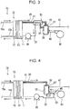
- the fuel cell system 1c further includes a first heat exchanger 51.
- the first heat exchanger 51 exchanges heat between a first fluid, which is a fluid flowing in the first path 21 and containing the mediator, and a second fluid, which is a fluid flowing in the second path 22 and containing the mediator.
- the second fluid, flowing in the second path 22 and containing the mediator is typically hotter than the first fluid, flowing in the first path 21 and containing the mediator, because of the heat produced with the oxidation of the mediator at the regenerator 20.
- the heat exchange between the first and second fluids at the first heat exchanger 51 therefore cools the second fluid. This helps the mediator to be supplied at a lowered temperature to the cathode 11, thereby helping extend the service life of the fuel cell 10.
- the first fluid moreover, is heated by the heat exchange between the first and second fluids at the first heat exchanger 51, helping the mediator-containing solution to be supplied at an increased temperature to the regenerator 20.
- This helps maintain the internal temperature of the regenerator 20 at a desired temperature, thereby helping accelerate the oxidation of the mediator.
- the fuel cell system 1c further includes, for example, a thermal insulator 24.
- the thermal insulator 24 covers the second path 22 between the regenerator 20 and the second-fluid inlet of the first heat exchanger 51, thereby keeping the second fluid hot while it is supplied to the first heat exchanger 51.
- the second fluid supplied to the first heat exchanger 51 is therefore hotter than the first fluid supplied to the first heat exchanger 51, helping achieve a large difference in temperature between the first and second fluids at the first heat exchanger 51. This makes the heat exchange between the first and second fluids at the first heat exchanger 51 more efficient.
- the second fluid After passing through the first heat exchanger 51, the second fluid is further cooled in the second path 22 between the second-fluid outlet of the first heat exchanger 51 and the cathode 11.
- the mediator is therefore supplied in an appropriately cooled state to the cathode 11.
- the second path 22 between the second-fluid inlet of the first heat exchanger 51 and the regenerator 20 is shorter than the second path 22 between the second-fluid outlet of the first heat exchanger 51 and the cathode 11. This ensures a larger difference in temperature between the first and second fluids at the first heat exchanger 51 and appropriate cooling of the mediator in the second path 22 between the second-fluid outlet of the first heat exchanger 51 and the cathode 11.
- the forms of covering contemplated by the verb "cover” can include thermal insulation achieved by putting the thermal insulator 24 directly on the component(s) that forms the second path 22 and covering the second path 22 with the thermal insulator 24 with a space or a certain material interposed therebetween.
- the first heat exchanger 51 can be of any type as long as it is capable of exchanging heat between the first and second fluids.
- the first heat exchanger 51 has, for example, at least one of features (i) to (iii) listed below.
- the first heat exchanger 51 can be, for example, a plate heat exchanger, a double-pipe heat exchanger, or a shell-and-tube heat exchanger.
- the fuel cell system 1c includes, for example, a first thermal insulator 26 and a second thermal insulator 27. At least one of the first and second thermal insulators 26 and 27 may be omitted, for example if the first fluid is sufficiently heated by the heat exchange between the first and second fluids at the first heat exchanger 51.
- the fuel cell system 1d further includes a second heat exchanger 52.
- the second heat exchanger 52 exchanges heat between the oxidant in the oxidant feed path 45 and the second fluid, flowing in the second path 22 and containing the mediator.
- the oxidant e.g., air
- the heat exchange between the oxidant and the second fluid at the second heat exchanger 52 therefore cools the second fluid. This helps the mediator supplied to the cathode 11 to cool down, thereby helping extend the service life of the fuel cell 10.
- the oxidant moreover, is heated by the heat exchange between the oxidant and the second fluid at the second heat exchanger 52, helping the oxidant to be supplied at an increased temperature to the regenerator 20. This helps maintain the internal temperature of the regenerator 20 at a desired temperature, thereby helping accelerate the oxidation of the mediator.
- the second heat exchanger 52 can be of any type as long as it is capable of exchanging heat between the oxidant and the second fluid.
- the second heat exchanger 52 has, for example, at least one of features (I) to (III) listed below.
- the second heat exchanger 52 can be, for example, a plate heat exchanger or a fin-tube heat exchanger.
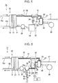
- the fuel cell system 1e further includes a tank 29.
- the tank 29 is in the second path 22 and retains the mediator oxidized at the regenerator 20. This helps make the regenerator 20 smaller in size. Moreover, by reducing the external supply of energy required to maintain the inside of the regenerator 20 at a desired temperature, the tank 29 helps improve the efficiency of the fuel cell system 1e.
- the tank 29 is located, for example, in the second path 22 between the regenerator 20 and the pump 30.
- the tank 29 may be in the second path 22 between the pump 30 and the cathode 11.
- the fuel cell system 1e further includes, for example, a valve 28.
- the valve 28 is located, for example, in the second path 22.
- the valve 28 is located, for example, in the second path 22 between the regenerator 20 and the tank 29.
- the valve 28 can be, to name a few, an on-off valve, such as a solenoid valve, or a flow regulator valve, such as a motor valve. By controlling the valve 28, the flow of the mediator-containing solution in the second path 22 can be regulated.
- At least one of the first and second thermal insulators 26 and 27 may be omitted, for example if the first fluid is sufficiently heated by the heat exchange between the first and second fluids at the first heat exchanger 51.
- the first heat exchanger 51 may be omitted, for example if the regenerator 20 is sufficiently small.
- the fuel cell system 1f illustrated in Fig. 6 has the same structure as the fuel cell system 1e unless otherwise specified.
- the fuel cell system 1f further includes a liquid delivery path 60 and a controller 70.
- the liquid delivery path 60 is connected to the tank 29 and is used to supply a liquid for diluting the mediator to the tank 29.
- An example of a liquid for diluting the mediator is water.
- the controller 70 regulates the flow rate of the liquid in the liquid delivery path 60.
- the mediator concentration of the mediator solution is controlled to a desired range because at the tank 29, the mediator can be diluted with the liquid supplied through the liquid delivery path 60 to the tank 29.
- the fuel cell system 1f further includes, for example, a valve 64.
- the valve 64 is located, for example, in the liquid delivery path 60.
- the valve 64 can be, to name a few, an on-off valve, such as a solenoid valve, or a flow regulator valve, such as a motor valve.
- the controller 70 regulates the flow rate of the liquid in the liquid delivery path 60.
- the controller 70 is a digital computer on which a predetermined program has been installed operably, and the controller 70 and the valve 64 are wired or wirelessly linked together so that the valve 64 can receive control signals sent from the controller 70.
- the fuel cell system 1f further includes, for example, a sensor 29a.
- the sensor 29a detects at least one selected from the group consisting of the pH, electrostatic potential, and mediator concentration of the mediator solution retained in the tank 29.
- the sensor 29a is wired or wirelessly linked to the controller 70, so that the controller 70 can acquire information that indicates values detected by the sensor 29a.
- the controller 70 determines the volume of liquid to be supplied to the tank 29.
- the controller 70 also generates, on the basis of the determined volume, control signals for controlling the valve 64 and sends them to the valve 64.
- the liquid flowing in the liquid delivery path 60 can be of any kind as long as the mediator can be diluted with it.
- An example of a liquid flowing in the liquid delivery path 60 is water.
- the liquid flowing in the liquid delivery path 60 can come from any source. For example, condensation obtained by condensing steam flowing in the gas discharge path 47 may be supplied through the liquid delivery path 60 to the tank 29. This enables effective use of condensation for the purpose of diluting the mediator.
- the second path 22 includes, for example, an upstream path 22u.
- the upstream path 22u connects the regenerator 20 and the tank 29 together.
- the upstream path 22u has a first portion 22f and a second portion 22s.
- the first portion 22f extends from the regenerator 20 to the tank 29.
- the second portion 22s allows the mediator to cool down while bypassing at least part of the first portion 22f.
- the controller 70 regulates, for example, the flow rate of the mediator in the first portion 22f and that in the second portion 22s.
- the release of heat from the mediator solution in the upstream path 22u, and therefore the temperature of the temperature of the mediator solution supplied to the tank 29, can be controlled.
- allowing the mediator to flow faster in the first portion 22f than in the second portion 22s helps the mediator solution to be supplied at an increased temperature to the tank 29, compared with the opposite.
- the liquid supplied through the liquid delivery path 60 to the tank 29 may be colder than a desired temperature.
- the temperature of the mediator solution supplied to the tank 29 can be controlled in accordance with the temperature of the liquid supplied through the liquid delivery path 60 to the tank 29. As a result, the temperature of the mediator solution retained in the tank 29 can be controlled to a desired range.
- the second portion 22s extends, for example, to bypass part of the first portion 22f.
- part of the second portion 22s is located in the first heat exchanger 51.
- the heat exchange between the mediator solution in the second portion 22s and that in the first path 21 cools the mediator in the second portion 22s.
- the first heat exchanger 51 is optional.
- the first portion 22f may be covered with a thermal insulator. This ensures the mediator solution flowing in the first portion 22f is kept warm. Since the mediator solution is kept warm in the first portion 22f and cooled in the second portion 22s, the temperature of the mediator solution supplied to the tank 29 can be controlled over a wide range. Covering the first portion 22f with a thermal insulator is optional.
- the fuel cell system 1f further includes, for example, temperature sensors 29b and 62.
- the temperature sensor 29b detects the temperature of the mediator solution in the tank 29.
- the temperature sensor 29b is located, for example, inside the tank 29.
- the temperature sensor 62 detects the temperature of the liquid for diluting the mediator.
- the temperature sensor 62 is located, for example, in the liquid delivery path 60.
- the temperature sensor 62 may be in a tank (not illustrated) that retains the liquid for diluting the mediator.
- Each of the temperature sensors 29b and 62 is wired or wirelessly linked to the controller 70, so that the controller 70 can acquire information that indicates temperatures detected by the temperature sensors 29b and 62.
- controller 70 to regulate the flow rate of the mediator in the first portion 22f and that in the second portion 22s on the basis of temperatures detected by the temperature sensors 29b and 62.
- the controller 70 regulates the flow rate of the mediator in the first portion 22f and that in the second portion 22s by controlling a valve 28.
- the valve 28 is located, for example, in the first portion 22f.
- the valve 28 may be in the second portion 22s.
- the valve 28 may connect the first and second portions 22f and 22s together.
- the valve 28 in this case can be a three-way valve.
- At least part of the tank 29 may be covered with a thermal insulator. Covering the tank 29 with a thermal insulator is optional. For example, the tank 29 does not need to be covered with a thermal insulator if the second path 22 between the tank 29 and the cathode 11 is short. Alternatively, the tank 29 does not need to be covered with a thermal insulator if the operation of the controller 70 considers the release of heat from the second path 22 between the tank 29 and the cathode 11.
- step S1 the procedure illustrated in Fig. 7 is executed regularly while the fuel cell system 1f is operating.
- step S2 the controller 70 acquires a value Vd detected by the sensor 29a.
- step S2 the controller 70 determines whether or not the detected value Vd exceeds a predetermined threshold. This predetermined threshold corresponds to the highest concentration of the mediator in the mediator solution suitable for supply to the cathode 11. If the result in step S2 is positive, the procedure goes to step S3, in which the controller 70 controls the valve 64 to increase the flow rate of the liquid in the liquid delivery path 60. For example, the controller 70 increases the opening of the valve 64.
- step S4 in which the controller 70 acquires temperatures Tt and Ts detected by the temperature sensors 29b and 62.
- step S5 in which the controller 70 controls the valve 28 on the basis of the detected temperatures Tt and Ts. For example, the controller 70 adjusts the opening of the valve 28 to bring the detected temperature Tt closer to a target temperature.
- step S5 a set of operations ends.
- step S2 If the result in step S2 is negative, the procedure goes to step S6, in which the controller 70 controls the valve 64 to reduce the flow rate of the liquid in the liquid delivery path 60. For example, the controller 70 reduces the opening of the valve 64.
- step S7 in which the controller 70 acquires temperatures Tt and Ts detected by the temperature sensors 29b and 62.
- step S8 in which the controller 70 controls the valve 28 on the basis of the detected temperatures Tt and Ts. For example, the controller 70 adjusts the opening of the valve 28 to bring the detected temperature Tt closer to a target temperature. After this, a set of operations ends.
- the structural elements of the fuel cell systems 1a to 1f can be used in combination unless technically contradictory.
Landscapes
- Life Sciences & Earth Sciences (AREA)
- Engineering & Computer Science (AREA)
- Manufacturing & Machinery (AREA)
- Sustainable Development (AREA)
- Sustainable Energy (AREA)
- Chemical & Material Sciences (AREA)
- Chemical Kinetics & Catalysis (AREA)
- Electrochemistry (AREA)
- General Chemical & Material Sciences (AREA)
- Fuel Cell (AREA)
Description
- The present disclosure relates to a fuel cell system.
- A fuel cell system that uses a catholyte containing a redox couple is known.
- For example, Japanese Unexamined Patent Application Publication (Translation of PCT Application) No.
2017-500692 JP S63-37572 US 2012/251912 A1 ,US 2012/107702 A1 ,US 4407902 A , andGB 2513413 A - The technology described in Japanese Unexamined Patent Application Publication (Translation of
PCT Application) No. 2017-500692 - In one general aspect, the techniques disclosed here feature a fuel cell system. The fuel cell system includes: a fuel cell that includes an anode and a cathode and generates electricity by reducing a mediator at the cathode; a regenerator that oxidizes the mediator reduced by the cathode; a first path that leads from the cathode to the regenerator and through which the mediator reduced by and discharged from the cathode is guided to the regenerator; a second path that leads from the regenerator to the cathode and through which the mediator oxidized at the regenerator is returned to the cathode; and a first heat exchanger that exchanges heat between a first fluid and a second fluid, the first fluid being a fluid flowing in the first path and containing the mediator reduced by cathode, and the second fluid being a fluid flowing in the second path and containing the mediator oxidized at the regenerator.
- This fuel cell system is advantageous in extending the service life of a fuel cell.
-
-
Fig. 1 illustrates an example of a fuel cell system according to the present disclosure; -
Fig. 2 illustrates another example of a fuel cell system according to the present disclosure; -
Fig. 3 illustrates yet another example of a fuel cell system according to the present disclosure; -
Fig. 4 illustrates yet another example of a fuel cell system according to the present disclosure; -
Fig. 5 illustrates yet another example of a fuel cell system according to the present disclosure; -
Fig. 6 illustrates yet another example of a fuel cell system according to the present disclosure; and -
Fig. 7 is a flowchart representing a procedure executed in the fuel cell system illustrated inFig. 6 . - Fuel cells, such as solid-polymer fuel cells, are not very efficient in reactions for power generation primarily because the cathodic reduction of oxygen proceeds slowly. A potential solution to this is to supply a solution containing a readily reducible mediator to the cathode of the fuel cell. This eliminates the need for the use of platinum in making the cathode.
- The mediator reduced at the cathode is regenerated through oxidation by an oxidant and then can be recycled to the cathode. As a result, the mediator can be reduced and regenerated repeatedly. The oxidation of the mediator, however, is exothermic, and the heat produced tends to cause the solution containing the oxidized mediator, flowing toward the cathode, to be hot. A fuel cell usually incorporates a polymer electrolyte membrane or similar component, and the inventors have found that allowing such a hot mediator-containing solution to be supplied to the cathode often causes thermal degradation of the polymer electrolyte membrane or similar component and thereby prevents extended use of the fuel cell. After extensive research on how to combine the use of a mediator with an extended service life of a fuel cell, the inventors conceived an idea about the path for guiding the oxidized mediator to the cathode. The fuel cell system according to the present disclosure is based on this idea.
- A fuel cell system includes: a fuel cell that includes an anode and a cathode and generates electricity by reducing a mediator at the cathode; a regenerator that oxidizes the mediator reduced by the cathode; a first path that leads from the cathode to the regenerator and through which the mediator reduced by and discharged from the cathode is guided to the regenerator; a second path that leads from the regenerator to the cathode and through which the mediator oxidized at the regenerator is returned to the cathode; and a first heat exchanger that exchanges heat between a first fluid and a second fluid, the first fluid being a fluid flowing in the first path and containing the mediator reduced by cathode, and the second fluid being a fluid flowing in the second path and containing the mediator oxidized at the regenerator.
- The first aspect includes a second path through which the mediator oxidized at the regenerator is returned to the cathode. The mediator is therefore supplied at a lowered temperature to the cathode, preventing the associated degradation of components of the fuel cell. This helps extend the service life of the fuel cell in the fuel cell system.
- Specifically, the second fluid, flowing in the second path and containing the mediator, is hotter than the first fluid, flowing in the first path and containing the mediator, because of the heat produced with the oxidation of the mediator at the regenerator. The heat exchange between the first and second fluids at the first heat exchanger therefore cools the second fluid. The mediator supplied to the cathode is cooled, helping extend the service life of the fuel cell. The first fluid, moreover, is heated by the heat exchange between the first and second fluids at the first heat exchanger, helping the mediator to be supplied at an increased temperature to the regenerator. This helps maintain the internal temperature of the regenerator at a desired temperature, thereby accelerating the oxidation of the mediator.
- In a second aspect of the present disclosure, for example, the second path in the fuel cell system according to the first aspect releases more heat per second than the first path does. In the second aspect, much heat released from the second path helps cool the mediator in the second path appropriately. The mediator supplied to the cathode is cooled in a more reliable manner, helping extend the service life of the fuel cell. Moreover, little heat released from the first path prevents the mediator supplied to the regenerator from cooling easily. This helps maintain the internal temperature of the regenerator at a desired temperature, thereby accelerating the oxidation of the mediator.
- In a third aspect of the present disclosure, for example, at least part of the second path in the fuel cell system according to the first or second aspect is made of a material having a higher thermal conductivity than the material forming the first path. In the third aspect, the heat of the mediator in the second path easily goes out of the second path, helping the mediator in the second path to be cooled. The mediator to be supplied to the cathode is therefore cooled in a more reliable manner, helping extend the service life of the fuel cell.
- In a fourth aspect of the present disclosure, for example, the fuel cell system according to any one of the first to third aspects further includes a thermal insulator that covers at least part of the first path. In the fourth aspect, the thermal insulator prevents the mediator from cooling in the first path. This helps maintain the internal temperature of the regenerator at a desired temperature, thereby accelerating the oxidation of the mediator.
- In a fifth aspect of the present disclosure, for example, the fuel cell system according to any one of the first to fourth aspects further includes an oxidant feed path through which an oxidant is supplied to the regenerator; and a second heat exchanger that exchanges heat between the oxidant in the oxidant feed path and the second fluid, flowing in the second path and containing the mediator. In many cases, the oxidant (e.g., air) supplied to the regenerator through the oxidant feed path is colder than the second fluid, flowing in the second path and containing the mediator. The heat exchange between the oxidant and the second fluid at the second heat exchanger therefore cools the second fluid. The mediator supplied to the cathode is cooled, helping extend the service life of the fuel cell. The oxidant, moreover, is heated by the heat exchange between the oxidant and the second fluid at the second heat exchanger, ensuring the oxidant is supplied at an increased temperature to the regenerator. This helps maintain the internal temperature of the regenerator at a desired temperature, thereby accelerating the oxidation of the mediator.
- In a sixth aspect of the present disclosure, for example, the fuel cell system according to the first to fifth aspects further includes a tank that is disposed in the second path and retains the mediator oxidized at the regenerator. In the sixth aspect, it is easier to make the regenerator smaller in size because the tank takes charge of retaining the mediator oxidized at the regenerator. The use of a smaller regenerator reduces the external supply of energy required to maintain the inside of the regenerator at a desired temperature, thereby making the fuel cell system more efficient.
- In a seventh aspect of the present disclosure, for example, the fuel cell system according to the sixth aspect further includes a liquid delivery path that is connected to the tank and through which a liquid for diluting the mediator is supplied to the tank; and a controller that regulates the flow rate of the liquid in the liquid delivery path. In the seventh aspect, the concentration of the mediator can be controlled to a desired range because the mediator can be diluted with the liquid supplied through the liquid delivery path to the tank as necessary. The temperature of the mediator in the tank can also be controlled to a desired range.
- In an eighth aspect of the present disclosure, for example, the second path in the fuel cell system according to the seventh aspect includes an upstream path that connects the regenerator and the tank; the upstream path has a first portion that extends from the regenerator to the tank and a second portion that allows the mediator to cool down while bypassing at least part of the first portion; and the controller regulates the flow rate of the mediator in the first portion and the flow rate of the mediator in the second portion. In the eighth aspect, the temperature of the mediator supplied to the tank can be controlled by adjusting the flow rate of the mediator in the first portion and that in the second portion.
- In a ninth aspect of the present disclosure, for example, the fuel cell system according to any one of the first to eighth aspects further includes a thermal insulator that covers at least part of the regenerator. In the ninth aspect, the thermal insulator helps maintain the inside of the regenerator at a desired temperature. The insulator also reduces the external supply of energy required to maintain the inside of the regenerator at a desired temperature, thereby helping improve the efficiency of the fuel cell system.
- In a tenth aspect of the present disclosure, for example, the fuel cell system according to any one of the first to ninth aspects further includes a heater that heats the inside of the regenerator. In the tenth aspect, the inside of the regenerator can be maintained at a desired temperature by turning on the heater as necessary.
- The following describes embodiments of the present disclosure with reference to drawings. It should be noted that the following embodiments are merely for illustrative purposes, and fuel cell systems according to the present disclosure are not limited to these embodiments.
- As illustrated in
Fig. 1 , afuel cell system 1a includes afuel cell 10, aregenerator 20, afirst path 21, and asecond path 22. Thefuel cell 10 has acathode 11 and ananode 12 and generates electricity by reducing a mediator at thecathode 11. Theregenerator 20 oxidizes the mediator reduced by thecathode 11. Thefirst path 21 leads from thecathode 11 to theregenerator 20, and through thisfirst path 21 the mediator discharged from thecathode 11 is guided to theregenerator 20. Thesecond path 22 leads from theregenerator 20 to thecathode 11, and through thissecond path 22 the mediator oxidized at theregenerator 20 is returned to thecathode 11 while cooling down. - In the
fuel cell system 1a, any kind of fuel and any kind of oxidant for regenerating the mediator can be used. For example, thefuel cell system 1a operates with hydrogen as the fuel and air as the oxidant. InFig. 1 , the solid-line arrows represent the flow of the fuel, the broken-line arrows represent the flow of the mediator, and the arrow with a dash dot line represents the flow of the oxidant. - The
fuel cell 10 is, for example, a solid-polymer fuel cell. Thecathode 11 can be made of a known material for the cathode of a solid-polymer fuel cell. Although the cathode of ordinary solid-polymer fuel cells contains platinum, the material for thecathode 11 does not need to contain it because the mediator is more reducible at thecathode 11 than oxygen, and this eliminates the need for a catalyst for activating the oxidant. Theanode 12 can be made of a known material for the anode of a solid-polymer fuel cell. Typically, thefuel cell 10 further includes anelectrolyte membrane 13. Theelectrolyte membrane 13 is between thecathode 11 and theanode 12 and conducts protons. Thecathode 11 and theanode 12 are separated by theelectrolyte membrane 13. Theelectrolyte membrane 13 can be made of a known material for the electrolyte of a solid-polymer fuel cell, such as Nafion®. - While the
fuel cell 10 is operating, theanode 12 is supplied with, for example, fuel gas containing hydrogen gas. At theanode 12, the hydrogen is separated into protons H+ and electrons e-. The protons then move to thecathode 11 through theelectrolyte membrane 13, whereas the electrons e- move to thecathode 11 via an external circuit (not illustrated). Thecathode 11 is supplied with, for example, a mediator-containing solution while thefuel cell 10 is operating. In this solution, the mediator is in its oxidized state Medox. The oxidized mediator Medox is reduced at thecathode 11, turning into a reduced mediator Medred, and leaves thefuel cell 10. The solution containing the reduced mediator Medred is supplied to theregenerator 20 through thefirst path 21. At theregenerator 20, the reduced mediator Medred is oxidized by oxygen, the active ingredient of the oxidant, turning into the oxidized form Medox of the mediator. This is the regeneration of the mediator. The mediator regenerated at theregenerator 20 is supplied to thecathode 11 through thesecond path 22. - The oxidation of the reduced mediator Medred is typically exothermic. The inside of the
regenerator 20 therefore tends to be hot (e.g., 100°C). This means, if the solution containing the mediator regenerated at theregenerator 20 were supplied to thecathode 11 while keeping its temperature, theelectrolyte membrane 13 or similar component of thefuel cell 10 would degrade easily. In thefuel cell system 1a, however, thesecond path 22 guides the mediator oxidized at theregenerator 20 to thecathode 11 while cooling it down. The mediator-containing solution supplied to thecathode 11 is cooled to a predetermined temperature (e.g., 80°C or less), thereby preventing the degradation of components of thefuel cell 10. In thefuel cell system 1a, therefore, thefuel cell 10 tends to have an extended service life. Thefuel cell 10 can even be cooled using the mediator-containing solution. - In the
fuel cell system 1a, for example, thesecond path 22 releases more heat per second than thefirst path 21 does. The resulting more appropriate cooling of thesecond path 22 helps the mediator-containing solution to be supplied at an appropriate temperature to thecathode 11, thereby helping extend the service life of thefuel cell 10. To accelerate the oxidation of the mediator at theregenerator 20, it is advantageous that the inside of theregenerator 20 be hot. While thefuel cell system 1a is operating normally, little heat released from thefirst path 21 prevents the mediator-containing solution supplied to the regenerator 20 from cooling easily. This helps maintain the internal temperature of theregenerator 20 at a desired temperature, thereby helping accelerate the oxidation of the mediator at theregenerator 20. In an exemplary configuration, thesecond path 22 releases more heat per second than thefirst path 21 does during the normal operation of thefuel cell system 1a. The normal operation of thefuel cell system 1a is to continue generating a predetermined output power (e.g., 100 W or more) for a predetermined period of time. - In the
fuel cell system 1a, for example, at least part of thesecond path 22 is made of a material that has a higher thermal conductivity than the material forming thefirst path 21. This helps the heat of the mediator-containing solution in thesecond path 22 go out of thesecond path 22, thereby helping the mediator-containing solution to be cooled in thesecond path 22. The mediator to be supplied to thecathode 11 is therefore cooled in a more reliable manner, helping extend the service life of thefuel cell 10. The thermal conductivity of the material for the tubing defining thefirst path 21 and that of the material for the tubing defining thesecond path 22 are, for example, values at 25°C. - In the
fuel cell system 1a, for example, thesecond path 22 is longer than thefirst path 21. This helps increase the release of heat from the mediator-containing solution in thesecond path 22, thereby helping the mediator-containing solution to be cooled appropriately in thesecond path 22. In an exemplary configuration, the tubing defining thesecond path 22 has a greater surface area than that defining thefirst path 21. This also helps increase the release of heat from the mediator-containing solution in thesecond path 22. The tubing defining thesecond path 22 may be made of a metallic material. The tubing defining thesecond path 22 may be fitted with a fin. At least part of the tubing defining thesecond path 22 may be in contact with a space through which air can pass. For example, thefuel cell system 1a may include an enclosure (not illustrated) having an air inlet and an air outlet, and at least part of the tubing defining thesecond path 22 may be in contact with the air passage extending from the air inlet to the air outlet of this enclosure. Thefuel cell system 1a may further include, for example, a fan or blower (not illustrated). In an exemplary configuration, the fan or blower operates to produce a stream of air that passes across at least part of the tubing defining thesecond path 22. - Any kind of mediator can be used as long as it is more reducible than oxygen gas and can be reduced and oxidized repeatedly. To name a few, the mediator can be a polyoxometalate, metal ions, or a metal complex. Polyoxometalates that can be used include phosphomolybdic acid, phosphovanadic acid, and phosphotungstic acid, and metals polyoxometalates can have include vanadium, molybdenum, and tungsten. Examples of metal complexes include porphyrin metal complexes, TEMPO (2,2,6,6-tetramethylpiperidine 1-oxyl)-coordinated metal complexes, and metal complexes coordinated by an oxidase or its derivative. The oxidase can be, to name a few, galactose oxidase, bilirubin oxidase, or glucose oxidase.
- The mediator typically circulates between the
cathode 11 and theregenerator 20 in solution form. The higher the mediator concentration of the solution is, the faster the mediator is reduced at thecathode 11. It is therefore advantageous that the mediator be highly soluble in a predetermined solvent, such as water, at the temperature at which it is used. The mediator solution may contain multiple mediators. The solvent, too, can be of any kind. An example of a solvent in the mediator solution is water, and the mediator solution may contain an acid component, such as sulfuric acid or phosphoric acid. The pH of the mediator solution may be acidic. The mediator solution may contain an appropriate electrolyte. - As illustrated in
Fig. 1 , thefuel cell system 1a further includes, for example, apump 30. Thepump 30 operates to guide the mediator-containing solution to theregenerator 20 through thefirst path 21 and to return the mediator-containing solution to thecathode 11 through thesecond path 22. Thepump 30 is located, for example, in thesecond path 22. Thepump 30 may be in thefirst path 21. Thepump 30 is, for example, a displacement pump, such as a piston pump, a plunger pump, a gear pump, or a vane pump. There may be a regulator in the first orsecond path - The
fuel cell system 1a further includes, for example, adelivery route 15a and arecovery route 15b. Each of the delivery andrecovery routes anode 12. Through thedelivery route 15a hydrogencontaining fuel is supplied to theanode 12, and unreacted fuel is recovered from thefuel cell 10 through therecovery route 15b. - The
fuel cell system 1a further includes, for example, anoxidant feed path 45. Theoxidant feed path 45 guides an oxidant to theregenerator 20. Thefuel cell system 1a further includes, for example, ablower 40, and air sent out from theblower 40 is supplied to theregenerator 20 through theoxidant feed path 45. In an exemplary configuration, theblower 40 operates to take in external air and send it out to theoxidant feed path 45. - The
regenerator 20 is not limited to a particular form as long as it allows a solution containing the reduced mediator to come into contact with the oxidant. Theregenerator 20 may be a bath reactor or may be a column reactor. In an exemplary configuration, theregenerator 20 retains a solution containing the mediator. In this case the air that has passed through theoxidant feed path 45 is, for example, blown into the mediator-containing solution retained in theregenerator 20. The mediator solution may be in jet stream or tiny droplet (mist) form. The air in this case is, for example, blown out from the exit of theoxidant feed path 45 toward the jet stream or tiny droplets of the mediator solution. This allows the mediator solution to meet the gas present inside theregenerator 20 with a larger interface, thereby helping accelerate the oxidation of the mediator. - The
fuel cell system 1a further includes, for example, agas discharge path 47. At theregenerator 20, water is produced with the oxidation of the mediator. Since, as mentioned above, the inside of theregenerator 20 can be maintained at a relatively high temperature, part of the produced water evaporates into steam. The steam in theregenerator 20 is discharged from theregenerator 20 and flows through thegas discharge path 47. This prevents the mediator solution inside the regenerator 20 from being deficient in the mediator, thereby preventing the associated decrease in the efficiency of thefuel cell 10 in power generation. Thegas discharge path 47 may also be used to discharge unreacted oxidant out of theregenerator 20. - As illustrated in
Fig. 1 , thefuel cell system 1a further includes, for example, aheater 25. Theheater 25 heats the inside of theregenerator 20. Heating the inside of theregenerator 20 with theheater 25 helps the water produced with the oxidation of the mediator evaporate. Since the mediator is usually nonvolatile, this operation of heating eliminates water from theregenerator 20, thereby preventing the mediator solution inside the regenerator 20 from being deficient in the mediator. Moreover, the oxidation of the mediator is accelerated because the internal temperature of theregenerator 20 is maintained within a desired range. - The
heater 25 can be of any type as long as it is capable of heating the inside of theregenerator 20. Theheater 25 can be, for example, an electrically powered resistance heater or a heater having a passage for a heating medium to pass through. Theheater 25 has been fitted on, for example, the outer surface of theregenerator 20. For example, theheater 25 covers at least part of the outer surface of theregenerator 20. Theheater 25 may surround at least part of the outer surface of theregenerator 20. Theheater 25 may alternatively be inside theregenerator 20. Thefuel cell system 1a may further include, for example, a stirrer (not illustrated). The stirrer in this case stirs the mediator solution inside theregenerator 20, helping maintain the temperature of the mediator solution inside theregenerator 20 spatially uniform. - The
heater 25 does not need to produce heat throughout the oxidation of the mediator at theregenerator 20. The oxidation of a mediator is exothermic in many cases. Theheater 25 may therefore be off while the heat produced with the oxidation of the mediator is maintaining the inside of theregenerator 20 at a temperature appropriate for the prevention of the dilution of the mediator in the mediator solution. Theheater 25 produces heat in the event of a low external temperature or other circumstances that make it difficult to keep the internal temperature of theregenerator 20 within a desired range. Thefuel cell system 1a may further include a temperature sensor (not illustrated). This temperature sensor, for example a thermistor-based or thermocouple-based one, detects the internal temperature of theregenerator 20. In an exemplary configuration, the heat production by theheater 25 is controlled on the basis of the temperature detected by the temperature sensor. Theheater 25 can be omitted in certain cases. - The
fuel cell system 1a can be modified for various purposes. For example, thefuel cell system 1a may be modified to further include a heat exchanger that exchanges heat between the oxidant flowing in theoxidant feed path 45 and gas flowing in thegas discharge path 47. The heat exchange between the oxidant flowing in theoxidant feed path 45 and gas flowing in thegas discharge path 47 heats the oxidant flowing in theoxidant feed path 45, thereby ensuring that the oxidant is supplied at an increased temperature to theregenerator 20. This helps accelerate the oxidation of the mediator. The gas flowing in thegas discharge path 47, moreover, is cooled by the heat exchange between the oxidant flowing in theoxidant feed path 45 and the gas flowing in thegas discharge path 47, ensuring safe emission of this gas from thefuel cell system 1a. In this variation there may be a thermal insulator that covers at least part of the section of theoxidant feed path 45 from the heat exchanger to theregenerator 20, or there may be a thermal insulator that covers at least part of the section of thegas discharge path 47 from theregenerator 20 to the heat exchanger. In an exemplary configuration, thefuel cell system 1a may further include, besides this heat exchanger, a heater that heats the oxidant flowing in theoxidant feed path 45. In this case the heater heats, for example, the oxidant flowing between the oxidant outlet of the heat exchanger and the outlet of thefirst path 21. - The gas flowing in the
gas discharge path 47 contains steam. In the above variation, therefore, condensation can form at the heat exchanger. As can be understood from this, the heat exchanger can serve as a condenser. In an exemplary configuration, a water drain path is connected to the heat exchanger, and the condensation is discharged out of the heat exchanger through the water drain path. The condensation may be used for a predetermined process in thefuel cell system 1a. - The
fuel cell system 1a may be changed as in thefuel cell system 1b illustrated inFig. 2 , thefuel cell system 1c illustrated inFig. 3 , thefuel cell system 1d illustrated inFig. 4 , thefuel cell system 1e illustrated inFig. 5 , or thefuel cell system 1f illustrated inFig. 6 . Unless otherwise specified, the structure of thefuel cell systems 1b to 1f is the same as that of thefuel cell system 1a. Any structural element of thefuel cell systems 1b to 1f that is also used in thefuel cell system 1a or corresponds to a structural element of thefuel cell system 1a is referenced by the same designator as in thefuel cell system 1a without a detailed description. A description of thefuel cell system 1a is also true for thefuel cell systems 1b to 1f unless technically contradictory. - As illustrated in
Fig. 2 , thefuel cell system 1b further includes a firstthermal insulator 26. The firstthermal insulator 26 covers at least part of thefirst path 21. A hollow material that provides an air space can also be used as the firstthermal insulator 26. The firstthermal insulator 26 prevents the mediator-containing solution from cooling in thefirst path 21. This helps maintain the internal temperature of theregenerator 20 at a desired temperature, thereby helping accelerate the oxidation of the mediator. Moreover, the firstthermal insulator 26 reduces the external supply of energy required to maintain the inside of theregenerator 20 at a desired temperature, thereby helping improve the efficiency of thefuel cell system 1b. The firstthermal insulator 26 may cover the entirefirst path 21. Here, the forms of covering contemplated by the verb "cover" can include thermal insulation achieved by putting thethermal insulator 26 directly on the component(s) that forms thefirst path 21 and covering thefirst path 21 with thethermal insulator 26 with a space or a certain material interposed therebetween. - As illustrated in
Fig. 2 , thefuel cell system 1b further includes, for example, a secondthermal insulator 27. The secondthermal insulator 27 covers at least part of theregenerator 20. A hollow material that provides an air space can also be used as the secondthermal insulator 27. The secondthermal insulator 27 helps maintain the inside of theregenerator 20 at a desired temperature. Moreover, the secondthermal insulator 27 reduces the external supply of energy required to maintain the inside of theregenerator 20 at a desired temperature, thereby helping improve the efficiency of thefuel cell system 1b. The secondthermal insulator 27 may cover theentire regenerator 20. Here, the forms of covering contemplated by the verb "cover" can include thermal insulation achieved by putting thethermal insulator 27 directly on theregenerator 20 and covering theregenerator 20 with thethermal insulator 27 with a space or a certain material interposed therebetween. - The
thermal insulators thermal insulators thermal insulators thermal insulators - As illustrated in
Fig. 3 , thefuel cell system 1c further includes afirst heat exchanger 51. Thefirst heat exchanger 51 exchanges heat between a first fluid, which is a fluid flowing in thefirst path 21 and containing the mediator, and a second fluid, which is a fluid flowing in thesecond path 22 and containing the mediator. The second fluid, flowing in thesecond path 22 and containing the mediator, is typically hotter than the first fluid, flowing in thefirst path 21 and containing the mediator, because of the heat produced with the oxidation of the mediator at theregenerator 20. The heat exchange between the first and second fluids at thefirst heat exchanger 51 therefore cools the second fluid. This helps the mediator to be supplied at a lowered temperature to thecathode 11, thereby helping extend the service life of thefuel cell 10. The first fluid, moreover, is heated by the heat exchange between the first and second fluids at thefirst heat exchanger 51, helping the mediator-containing solution to be supplied at an increased temperature to theregenerator 20. This helps maintain the internal temperature of theregenerator 20 at a desired temperature, thereby helping accelerate the oxidation of the mediator. - The
fuel cell system 1c further includes, for example, athermal insulator 24. Thethermal insulator 24 covers thesecond path 22 between the regenerator 20 and the second-fluid inlet of thefirst heat exchanger 51, thereby keeping the second fluid hot while it is supplied to thefirst heat exchanger 51. The second fluid supplied to thefirst heat exchanger 51 is therefore hotter than the first fluid supplied to thefirst heat exchanger 51, helping achieve a large difference in temperature between the first and second fluids at thefirst heat exchanger 51. This makes the heat exchange between the first and second fluids at thefirst heat exchanger 51 more efficient. After passing through thefirst heat exchanger 51, the second fluid is further cooled in thesecond path 22 between the second-fluid outlet of thefirst heat exchanger 51 and thecathode 11. The mediator is therefore supplied in an appropriately cooled state to thecathode 11. In an exemplary configuration, thesecond path 22 between the second-fluid inlet of thefirst heat exchanger 51 and theregenerator 20 is shorter than thesecond path 22 between the second-fluid outlet of thefirst heat exchanger 51 and thecathode 11. This ensures a larger difference in temperature between the first and second fluids at thefirst heat exchanger 51 and appropriate cooling of the mediator in thesecond path 22 between the second-fluid outlet of thefirst heat exchanger 51 and thecathode 11. Here, the forms of covering contemplated by the verb "cover" can include thermal insulation achieved by putting thethermal insulator 24 directly on the component(s) that forms thesecond path 22 and covering thesecond path 22 with thethermal insulator 24 with a space or a certain material interposed therebetween. - The
first heat exchanger 51 can be of any type as long as it is capable of exchanging heat between the first and second fluids. Thefirst heat exchanger 51 has, for example, at least one of features (i) to (iii) listed below. Thefirst heat exchanger 51 can be, for example, a plate heat exchanger, a double-pipe heat exchanger, or a shell-and-tube heat exchanger. - (i) The
second path 22 is positioned near thefirst path 21. - (ii) The component(s) forming the
second path 22 is in contact with the component(s) forming thefirst path 21. - (iii) The first and
second paths - The
fuel cell system 1c includes, for example, a firstthermal insulator 26 and a secondthermal insulator 27. At least one of the first and secondthermal insulators first heat exchanger 51. - As illustrated in
Fig. 4 , thefuel cell system 1d further includes asecond heat exchanger 52. Thesecond heat exchanger 52 exchanges heat between the oxidant in theoxidant feed path 45 and the second fluid, flowing in thesecond path 22 and containing the mediator. Typically, the oxidant (e.g., air) supplied to theregenerator 20 through theoxidant feed path 45 is colder than the second fluid, flowing in thesecond path 22 and containing the mediator. The heat exchange between the oxidant and the second fluid at thesecond heat exchanger 52 therefore cools the second fluid. This helps the mediator supplied to thecathode 11 to cool down, thereby helping extend the service life of thefuel cell 10. The oxidant, moreover, is heated by the heat exchange between the oxidant and the second fluid at thesecond heat exchanger 52, helping the oxidant to be supplied at an increased temperature to theregenerator 20. This helps maintain the internal temperature of theregenerator 20 at a desired temperature, thereby helping accelerate the oxidation of the mediator. - The
second heat exchanger 52 can be of any type as long as it is capable of exchanging heat between the oxidant and the second fluid. Thesecond heat exchanger 52 has, for example, at least one of features (I) to (III) listed below. Thesecond heat exchanger 52 can be, for example, a plate heat exchanger or a fin-tube heat exchanger. - (I) The
second path 22 is positioned near theoxidant feed path 45. - (II) The component(s) forming the
second path 22 is in contact with the component(s) forming theoxidant feed path 45. - (III) The
second path 22 and theoxidant feed path 45 are separated by a material suitable for the purpose of heat exchange. - As illustrated in
Fig. 5 , thefuel cell system 1e further includes atank 29. Thetank 29 is in thesecond path 22 and retains the mediator oxidized at theregenerator 20. This helps make theregenerator 20 smaller in size. Moreover, by reducing the external supply of energy required to maintain the inside of theregenerator 20 at a desired temperature, thetank 29 helps improve the efficiency of thefuel cell system 1e. Thetank 29 is located, for example, in thesecond path 22 between the regenerator 20 and thepump 30. Thetank 29 may be in thesecond path 22 between thepump 30 and thecathode 11. - The
fuel cell system 1e further includes, for example, avalve 28. Thevalve 28 is located, for example, in thesecond path 22. Thevalve 28 is located, for example, in thesecond path 22 between the regenerator 20 and thetank 29. Thevalve 28 can be, to name a few, an on-off valve, such as a solenoid valve, or a flow regulator valve, such as a motor valve. By controlling thevalve 28, the flow of the mediator-containing solution in thesecond path 22 can be regulated. - In the
fuel cell system 1e, at least one of the first and secondthermal insulators first heat exchanger 51. Moreover, in thefuel cell system 1e, thefirst heat exchanger 51 may be omitted, for example if theregenerator 20 is sufficiently small. - The
fuel cell system 1f illustrated inFig. 6 has the same structure as thefuel cell system 1e unless otherwise specified. Thefuel cell system 1f further includes aliquid delivery path 60 and acontroller 70. Theliquid delivery path 60 is connected to thetank 29 and is used to supply a liquid for diluting the mediator to thetank 29. An example of a liquid for diluting the mediator is water. Thecontroller 70 regulates the flow rate of the liquid in theliquid delivery path 60. - For stable operation of the
fuel cell system 1f, it is desirable to keep the mediator concentration of the mediator solution to be supplied to thecathode 11 within a predetermined range. As mentioned above, the internal temperature of theregenerator 20 is maintained high in order that part of the solvent in the mediator solution evaporate to prevent the mediator solution in the regenerator 20 from being deficient in the mediator. This means, upon discharge from theregenerator 20, the mediator solution may be too rich in the mediator. In thefuel cell system 1f, the concentration of the mediator can be controlled to a desired range because at thetank 29, the mediator can be diluted with the liquid supplied through theliquid delivery path 60 to thetank 29. - The
fuel cell system 1f further includes, for example, avalve 64. Thevalve 64 is located, for example, in theliquid delivery path 60. Thevalve 64 can be, to name a few, an on-off valve, such as a solenoid valve, or a flow regulator valve, such as a motor valve. By controlling thevalve 64, thecontroller 70 regulates the flow rate of the liquid in theliquid delivery path 60. In an exemplary configuration, thecontroller 70 is a digital computer on which a predetermined program has been installed operably, and thecontroller 70 and thevalve 64 are wired or wirelessly linked together so that thevalve 64 can receive control signals sent from thecontroller 70. - The
fuel cell system 1f further includes, for example, asensor 29a. Thesensor 29a detects at least one selected from the group consisting of the pH, electrostatic potential, and mediator concentration of the mediator solution retained in thetank 29. In an exemplary configuration, thesensor 29a is wired or wirelessly linked to thecontroller 70, so that thecontroller 70 can acquire information that indicates values detected by thesensor 29a. On the basis of the information indicating values detected by thesensor 29a, thecontroller 70 determines the volume of liquid to be supplied to thetank 29. Thecontroller 70 also generates, on the basis of the determined volume, control signals for controlling thevalve 64 and sends them to thevalve 64. - The liquid flowing in the
liquid delivery path 60 can be of any kind as long as the mediator can be diluted with it. An example of a liquid flowing in theliquid delivery path 60 is water. The liquid flowing in theliquid delivery path 60 can come from any source. For example, condensation obtained by condensing steam flowing in thegas discharge path 47 may be supplied through theliquid delivery path 60 to thetank 29. This enables effective use of condensation for the purpose of diluting the mediator. - In the
fuel cell system 1f, thesecond path 22 includes, for example, anupstream path 22u. Theupstream path 22u connects theregenerator 20 and thetank 29 together. Theupstream path 22u has afirst portion 22f and asecond portion 22s. Thefirst portion 22f extends from theregenerator 20 to thetank 29. Thesecond portion 22s allows the mediator to cool down while bypassing at least part of thefirst portion 22f. Thecontroller 70 regulates, for example, the flow rate of the mediator in thefirst portion 22f and that in thesecond portion 22s. - By adjusting the flow rate of the mediator in the
first portion 22f and that in thesecond portion 22s, the release of heat from the mediator solution in theupstream path 22u, and therefore the temperature of the temperature of the mediator solution supplied to thetank 29, can be controlled. For example, allowing the mediator to flow faster in thefirst portion 22f than in thesecond portion 22s helps the mediator solution to be supplied at an increased temperature to thetank 29, compared with the opposite. In certain cases, for example, the liquid supplied through theliquid delivery path 60 to thetank 29 may be colder than a desired temperature. In thefuel cell system 1f, the temperature of the mediator solution supplied to thetank 29 can be controlled in accordance with the temperature of the liquid supplied through theliquid delivery path 60 to thetank 29. As a result, the temperature of the mediator solution retained in thetank 29 can be controlled to a desired range. - As illustrated in
Fig. 6 , thesecond portion 22s extends, for example, to bypass part of thefirst portion 22f. In an exemplary configuration, part of thesecond portion 22s is located in thefirst heat exchanger 51. In this case the heat exchange between the mediator solution in thesecond portion 22s and that in thefirst path 21 cools the mediator in thesecond portion 22s. In thefuel cell system 1f, thefirst heat exchanger 51 is optional. - As illustrated in
Fig. 6 , at least part of thefirst portion 22f may be covered with a thermal insulator. This ensures the mediator solution flowing in thefirst portion 22f is kept warm. Since the mediator solution is kept warm in thefirst portion 22f and cooled in thesecond portion 22s, the temperature of the mediator solution supplied to thetank 29 can be controlled over a wide range. Covering thefirst portion 22f with a thermal insulator is optional. - The
fuel cell system 1f further includes, for example,temperature sensors temperature sensor 29b detects the temperature of the mediator solution in thetank 29. Thetemperature sensor 29b is located, for example, inside thetank 29. Thetemperature sensor 62 detects the temperature of the liquid for diluting the mediator. Thetemperature sensor 62 is located, for example, in theliquid delivery path 60. Thetemperature sensor 62 may be in a tank (not illustrated) that retains the liquid for diluting the mediator. Each of thetemperature sensors controller 70, so that thecontroller 70 can acquire information that indicates temperatures detected by thetemperature sensors controller 70 to regulate the flow rate of the mediator in thefirst portion 22f and that in thesecond portion 22s on the basis of temperatures detected by thetemperature sensors controller 70 regulates the flow rate of the mediator in thefirst portion 22f and that in thesecond portion 22s by controlling avalve 28. - In the
fuel cell system 1f, thevalve 28 is located, for example, in thefirst portion 22f. Thevalve 28 may be in thesecond portion 22s. Alternatively, thevalve 28 may connect the first andsecond portions valve 28 in this case can be a three-way valve. - In the
fuel cell system 1f, at least part of thetank 29 may be covered with a thermal insulator. Covering thetank 29 with a thermal insulator is optional. For example, thetank 29 does not need to be covered with a thermal insulator if thesecond path 22 between thetank 29 and thecathode 11 is short. Alternatively, thetank 29 does not need to be covered with a thermal insulator if the operation of thecontroller 70 considers the release of heat from thesecond path 22 between thetank 29 and thecathode 11. - The following gives an example of how in the
fuel cell system 1f the mediator concentration and temperature of the mediator solution in thetank 29 are regulated. In an exemplary configuration, the procedure illustrated inFig. 7 is executed regularly while thefuel cell system 1f is operating. In step S1, thecontroller 70 acquires a value Vd detected by thesensor 29a. In step S2, thecontroller 70 determines whether or not the detected value Vd exceeds a predetermined threshold. This predetermined threshold corresponds to the highest concentration of the mediator in the mediator solution suitable for supply to thecathode 11. If the result in step S2 is positive, the procedure goes to step S3, in which thecontroller 70 controls thevalve 64 to increase the flow rate of the liquid in theliquid delivery path 60. For example, thecontroller 70 increases the opening of thevalve 64. The procedure then goes to step S4, in which thecontroller 70 acquires temperatures Tt and Ts detected by thetemperature sensors controller 70 controls thevalve 28 on the basis of the detected temperatures Tt and Ts. For example, thecontroller 70 adjusts the opening of thevalve 28 to bring the detected temperature Tt closer to a target temperature. After step S5, a set of operations ends. - If the result in step S2 is negative, the procedure goes to step S6, in which the
controller 70 controls thevalve 64 to reduce the flow rate of the liquid in theliquid delivery path 60. For example, thecontroller 70 reduces the opening of thevalve 64. The procedure then goes to step S7, in which thecontroller 70 acquires temperatures Tt and Ts detected by thetemperature sensors controller 70 controls thevalve 28 on the basis of the detected temperatures Tt and Ts. For example, thecontroller 70 adjusts the opening of thevalve 28 to bring the detected temperature Tt closer to a target temperature. After this, a set of operations ends. - The structural elements of the
fuel cell systems 1a to 1f can be used in combination unless technically contradictory.
Claims (10)
- A fuel cell system comprising:a fuel cell that includes an anode and a cathode and generates electricity by reducing a mediator at the cathode;a regenerator that oxidizes the mediator reduced by the cathode;a first path that leads from the cathode to the regenerator and through which the mediator reduced by and discharged from the cathode is guided to the regenerator;a second path that leads from the regenerator to the cathode and through which the mediator oxidized at the regenerator is returned to the cathode; anda first heat exchanger that exchanges heat between a first fluid and a second fluid, the first fluid being a fluid flowing in the first path and containing the mediator reduced by cathode, and the second fluid being a fluid flowing in the second path and containing the mediator oxidized at the regenerator.
- The fuel cell system according to Claim 1, wherein the second path releases more heat per second than the first path does.
- The fuel cell system according to Claim 1, wherein at least part of the second path is made of a material that has a higher thermal conductivity than a material forming the first path.
- The fuel cell system according to Claim 1, further comprising a thermal insulator that covers at least part of the first path.
- The fuel cell system according to Claim 1, further comprising:an oxidant feed path through which an oxidant is supplied to the regenerator; anda second heat exchanger that exchanges heat between the oxidant in the oxidant feed path and the second fluid.
- The fuel cell system according to Claim 1, further comprising a tank that is disposed in the second path and retains the mediator oxidized at the regenerator.
- The fuel cell system according to Claim 6, further comprising:a liquid delivery path that is connected to the tank and through which a liquid for diluting the mediator is supplied to the tank; anda controller that regulates a flow rate of the liquid in the liquid delivery path.
- The fuel cell system according to Claim 7, wherein:the second path includes an upstream path that connects the regenerator and the tank;the upstream path has a first portion that extends from the regenerator to the tank and a second portion that allows the mediator to cool down while bypassing at least part of the first portion; andthe controller regulates a flow rate of the mediator in the first portion and a flow rate of the mediator in the second portion.
- The fuel cell system according to Claim 1, further comprising a thermal insulator that covers at least part of the regenerator.
- The fuel cell system according to Claim 1, further comprising a heater that heats an inside of the regenerator.
Applications Claiming Priority (1)
| Application Number | Priority Date | Filing Date | Title |
|---|---|---|---|
| JP2018111805 | 2018-06-12 |
Publications (2)
| Publication Number | Publication Date |
|---|---|
| EP3582311A1 EP3582311A1 (en) | 2019-12-18 |
| EP3582311B1 true EP3582311B1 (en) | 2020-09-23 |
Family
ID=66647076
Family Applications (1)
| Application Number | Title | Priority Date | Filing Date |
|---|---|---|---|
| EP19176117.0A Active EP3582311B1 (en) | 2018-06-12 | 2019-05-23 | Fuel cell system |
Country Status (4)
| Country | Link |
|---|---|
| US (1) | US11211622B2 (en) |
| EP (1) | EP3582311B1 (en) |
| JP (1) | JP7340773B2 (en) |
| CN (1) | CN110600782B (en) |
Families Citing this family (1)
| Publication number | Priority date | Publication date | Assignee | Title |
|---|---|---|---|---|
| KR102843023B1 (en) * | 2020-11-30 | 2025-08-05 | 현대자동차주식회사 | Integrated cooling control valve |
Family Cites Families (19)
| Publication number | Priority date | Publication date | Assignee | Title |
|---|---|---|---|---|
| US3271197A (en) * | 1962-04-24 | 1966-09-06 | Jr Ernest H Lyons | Process for producing electricity and furnace |
| US4407902A (en) * | 1980-12-08 | 1983-10-04 | Ford Motor Company | Chemically regenerable redox fuel cell and method of operating the same |
| JPS6337572A (en) * | 1986-08-01 | 1988-02-18 | Babcock Hitachi Kk | Redox flow type carbon monoxide/oxygen fuel cell |
| JPH04149965A (en) * | 1990-10-15 | 1992-05-22 | Agency Of Ind Science & Technol | Manufacture of vanadium electrolyte |
| US6048383A (en) * | 1998-10-08 | 2000-04-11 | International Fuel Cells, L.L.C. | Mass transfer composite membrane for a fuel cell power plant |
| FR2831333B1 (en) * | 2001-10-23 | 2004-07-23 | Renault | DEVICE FOR SUPPLYING GAS TO A FUEL CELL |
| DK200200828A (en) * | 2002-05-30 | 2003-12-01 | Reccat Aps | Self-regulating catalyst |
| US7862938B2 (en) * | 2007-02-05 | 2011-01-04 | Fuelcell Energy, Inc. | Integrated fuel cell and heat engine hybrid system for high efficiency power generation |
| GB0907795D0 (en) * | 2009-05-07 | 2009-06-17 | Acal Energy Ltd | Fuel cells |
| US20100291429A1 (en) * | 2009-05-12 | 2010-11-18 | Farmer Joseph C | Electrochemical Nanofluid or Particle Suspension Energy Conversion and Storage Device |
| JP2010282907A (en) * | 2009-06-08 | 2010-12-16 | Fuji Electric Systems Co Ltd | Air-cooled cooler |
| JP5384543B2 (en) * | 2011-03-04 | 2014-01-08 | 本田技研工業株式会社 | Fuel cell system |
| US8637197B2 (en) * | 2011-03-28 | 2014-01-28 | Robert J. Braun | High efficiency, reversible flow battery system for energy storage |
| JP2012226972A (en) * | 2011-04-20 | 2012-11-15 | Honda Motor Co Ltd | Redox fuel cell system and fuel cell vehicle |
| EP2772976B1 (en) * | 2013-02-27 | 2017-11-15 | Airbus Defence and Space GmbH | Regenerative fuel cell system with gas purification |
| GB2513413A (en) * | 2013-04-26 | 2014-10-29 | Acal Energy Ltd | Apparatus for cooling a fuel cell |
| GB2520259A (en) | 2013-11-12 | 2015-05-20 | Acal Energy Ltd | Fuel cell assembly and method |
| JP6382681B2 (en) * | 2014-04-30 | 2018-08-29 | 日本特殊陶業株式会社 | Fuel cell system |
| AU2016384671B2 (en) * | 2016-01-07 | 2019-10-31 | Kd Innovation Ltd. | Electrochemical systems for direct generation of electricity and heat pumping |
-
2019
- 2019-05-13 JP JP2019090924A patent/JP7340773B2/en active Active
- 2019-05-23 EP EP19176117.0A patent/EP3582311B1/en active Active
- 2019-05-30 US US16/426,658 patent/US11211622B2/en active Active
- 2019-05-30 CN CN201910460307.2A patent/CN110600782B/en active Active
Non-Patent Citations (1)
| Title |
|---|
| None * |
Also Published As
| Publication number | Publication date |
|---|---|
| CN110600782A (en) | 2019-12-20 |
| EP3582311A1 (en) | 2019-12-18 |
| US11211622B2 (en) | 2021-12-28 |
| JP7340773B2 (en) | 2023-09-08 |
| JP2019216090A (en) | 2019-12-19 |
| CN110600782B (en) | 2024-03-08 |
| US20190379073A1 (en) | 2019-12-12 |
Similar Documents
| Publication | Publication Date | Title |
|---|---|---|
| US7759010B2 (en) | Pulsed coolant control for improved stack cold starting | |
| US20210028468A1 (en) | Fuel cell system and method of operating same | |
| CN101197452A (en) | Supplemental coolant heating for fuel cells with metal plates | |
| US20180248206A1 (en) | Cooling system for a fuel cell, and a fuel cell system | |
| EP3582311B1 (en) | Fuel cell system | |
| JP2002198073A (en) | Control method of heat treatment system | |
| EP3576202A1 (en) | Fuel cell system | |
| US7960064B2 (en) | Rapid light-off catalytic combustor for fuel cell vehicle | |
| US11165079B2 (en) | Fuel cell system | |
| EP1724869B1 (en) | Anode tail gas recycle cooler and re-heater for a solid oxide fuel cell stack assembly | |
| EP2203950B1 (en) | Operation method at the time of load reduction of fuel cell system | |
| US20070178347A1 (en) | Coolant bypass for fuel cell stack | |
| JP2008112741A (en) | Fuel cell system | |
| JP2005322527A (en) | Fuel cell system | |
| EP3582312B1 (en) | Fuel cell system | |
| WO2002003490A1 (en) | Electrochemical conversion system | |
| JP2006172948A (en) | Fuel cell system | |
| JP2008226712A (en) | Fuel cell system and control method thereof | |
| KR101724753B1 (en) | Cooling water circulation apparatus for electricvehicle | |
| JP5102511B2 (en) | Fuel cell system | |
| EP3410525B1 (en) | Heated catalytic oxidizer for an enclosed humid environment | |
| JP4578890B2 (en) | Starting method of fuel cell system | |
| US11316184B2 (en) | Fuel cell system | |
| JP2008041466A (en) | Solid polymer electrolyte fuel cell | |
| JP2012178366A (en) | Polymer electrolyte fuel cell |
Legal Events
| Date | Code | Title | Description |
|---|---|---|---|
| PUAI | Public reference made under article 153(3) epc to a published international application that has entered the european phase |
Free format text: ORIGINAL CODE: 0009012 |
|
| STAA | Information on the status of an ep patent application or granted ep patent |
Free format text: STATUS: THE APPLICATION HAS BEEN PUBLISHED |
|
| AK | Designated contracting states |
Kind code of ref document: A1 Designated state(s): AL AT BE BG CH CY CZ DE DK EE ES FI FR GB GR HR HU IE IS IT LI LT LU LV MC MK MT NL NO PL PT RO RS SE SI SK SM TR |
|
| AX | Request for extension of the european patent |
Extension state: BA ME |
|
| STAA | Information on the status of an ep patent application or granted ep patent |
Free format text: STATUS: REQUEST FOR EXAMINATION WAS MADE |
|
| 17P | Request for examination filed |
Effective date: 20200220 |
|
| RBV | Designated contracting states (corrected) |
Designated state(s): AL AT BE BG CH CY CZ DE DK EE ES FI FR GB GR HR HU IE IS IT LI LT LU LV MC MK MT NL NO PL PT RO RS SE SI SK SM TR |
|
| GRAP | Despatch of communication of intention to grant a patent |
Free format text: ORIGINAL CODE: EPIDOSNIGR1 |
|
| STAA | Information on the status of an ep patent application or granted ep patent |
Free format text: STATUS: GRANT OF PATENT IS INTENDED |
|
| RIC1 | Information provided on ipc code assigned before grant |
Ipc: H01M 8/04791 20160101ALI20200306BHEP Ipc: H01M 8/04746 20160101ALI20200306BHEP Ipc: H01M 8/04007 20160101ALI20200306BHEP Ipc: H01M 8/20 20060101ALI20200306BHEP Ipc: H01M 8/04186 20160101ALI20200306BHEP Ipc: H01M 8/04082 20160101ALI20200306BHEP Ipc: H01M 8/18 20060101AFI20200306BHEP |
|
| INTG | Intention to grant announced |
Effective date: 20200408 |
|
| GRAS | Grant fee paid |
Free format text: ORIGINAL CODE: EPIDOSNIGR3 |
|
| GRAA | (expected) grant |
Free format text: ORIGINAL CODE: 0009210 |
|
| STAA | Information on the status of an ep patent application or granted ep patent |
Free format text: STATUS: THE PATENT HAS BEEN GRANTED |
|
| AK | Designated contracting states |
Kind code of ref document: B1 Designated state(s): AL AT BE BG CH CY CZ DE DK EE ES FI FR GB GR HR HU IE IS IT LI LT LU LV MC MK MT NL NO PL PT RO RS SE SI SK SM TR |
|
| REG | Reference to a national code |
Ref country code: GB Ref legal event code: FG4D |
|
| REG | Reference to a national code |
Ref country code: CH Ref legal event code: EP |
|
| REG | Reference to a national code |
Ref country code: DE Ref legal event code: R096 Ref document number: 602019000760 Country of ref document: DE |
|
| REG | Reference to a national code |
Ref country code: IE Ref legal event code: FG4D |
|
| REG | Reference to a national code |
Ref country code: AT Ref legal event code: REF Ref document number: 1317304 Country of ref document: AT Kind code of ref document: T Effective date: 20201015 |
|
| PG25 | Lapsed in a contracting state [announced via postgrant information from national office to epo] |
Ref country code: FI Free format text: LAPSE BECAUSE OF FAILURE TO SUBMIT A TRANSLATION OF THE DESCRIPTION OR TO PAY THE FEE WITHIN THE PRESCRIBED TIME-LIMIT Effective date: 20200923 Ref country code: HR Free format text: LAPSE BECAUSE OF FAILURE TO SUBMIT A TRANSLATION OF THE DESCRIPTION OR TO PAY THE FEE WITHIN THE PRESCRIBED TIME-LIMIT Effective date: 20200923 Ref country code: SE Free format text: LAPSE BECAUSE OF FAILURE TO SUBMIT A TRANSLATION OF THE DESCRIPTION OR TO PAY THE FEE WITHIN THE PRESCRIBED TIME-LIMIT Effective date: 20200923 Ref country code: BG Free format text: LAPSE BECAUSE OF FAILURE TO SUBMIT A TRANSLATION OF THE DESCRIPTION OR TO PAY THE FEE WITHIN THE PRESCRIBED TIME-LIMIT Effective date: 20201223 Ref country code: GR Free format text: LAPSE BECAUSE OF FAILURE TO SUBMIT A TRANSLATION OF THE DESCRIPTION OR TO PAY THE FEE WITHIN THE PRESCRIBED TIME-LIMIT Effective date: 20201224 Ref country code: NO Free format text: LAPSE BECAUSE OF FAILURE TO SUBMIT A TRANSLATION OF THE DESCRIPTION OR TO PAY THE FEE WITHIN THE PRESCRIBED TIME-LIMIT Effective date: 20201223 |
|
| REG | Reference to a national code |
Ref country code: AT Ref legal event code: MK05 Ref document number: 1317304 Country of ref document: AT Kind code of ref document: T Effective date: 20200923 |
|
| PG25 | Lapsed in a contracting state [announced via postgrant information from national office to epo] |
Ref country code: RS Free format text: LAPSE BECAUSE OF FAILURE TO SUBMIT A TRANSLATION OF THE DESCRIPTION OR TO PAY THE FEE WITHIN THE PRESCRIBED TIME-LIMIT Effective date: 20200923 Ref country code: LV Free format text: LAPSE BECAUSE OF FAILURE TO SUBMIT A TRANSLATION OF THE DESCRIPTION OR TO PAY THE FEE WITHIN THE PRESCRIBED TIME-LIMIT Effective date: 20200923 |
|
| REG | Reference to a national code |
Ref country code: NL Ref legal event code: MP Effective date: 20200923 |
|
| REG | Reference to a national code |
Ref country code: LT Ref legal event code: MG4D |
|
| PG25 | Lapsed in a contracting state [announced via postgrant information from national office to epo] |
Ref country code: LT Free format text: LAPSE BECAUSE OF FAILURE TO SUBMIT A TRANSLATION OF THE DESCRIPTION OR TO PAY THE FEE WITHIN THE PRESCRIBED TIME-LIMIT Effective date: 20200923 Ref country code: SM Free format text: LAPSE BECAUSE OF FAILURE TO SUBMIT A TRANSLATION OF THE DESCRIPTION OR TO PAY THE FEE WITHIN THE PRESCRIBED TIME-LIMIT Effective date: 20200923 Ref country code: PT Free format text: LAPSE BECAUSE OF FAILURE TO SUBMIT A TRANSLATION OF THE DESCRIPTION OR TO PAY THE FEE WITHIN THE PRESCRIBED TIME-LIMIT Effective date: 20210125 Ref country code: RO Free format text: LAPSE BECAUSE OF FAILURE TO SUBMIT A TRANSLATION OF THE DESCRIPTION OR TO PAY THE FEE WITHIN THE PRESCRIBED TIME-LIMIT Effective date: 20200923 Ref country code: CZ Free format text: LAPSE BECAUSE OF FAILURE TO SUBMIT A TRANSLATION OF THE DESCRIPTION OR TO PAY THE FEE WITHIN THE PRESCRIBED TIME-LIMIT Effective date: 20200923 Ref country code: EE Free format text: LAPSE BECAUSE OF FAILURE TO SUBMIT A TRANSLATION OF THE DESCRIPTION OR TO PAY THE FEE WITHIN THE PRESCRIBED TIME-LIMIT Effective date: 20200923 |
|
| PG25 | Lapsed in a contracting state [announced via postgrant information from national office to epo] |
Ref country code: PL Free format text: LAPSE BECAUSE OF FAILURE TO SUBMIT A TRANSLATION OF THE DESCRIPTION OR TO PAY THE FEE WITHIN THE PRESCRIBED TIME-LIMIT Effective date: 20200923 Ref country code: IS Free format text: LAPSE BECAUSE OF FAILURE TO SUBMIT A TRANSLATION OF THE DESCRIPTION OR TO PAY THE FEE WITHIN THE PRESCRIBED TIME-LIMIT Effective date: 20210123 Ref country code: AL Free format text: LAPSE BECAUSE OF FAILURE TO SUBMIT A TRANSLATION OF THE DESCRIPTION OR TO PAY THE FEE WITHIN THE PRESCRIBED TIME-LIMIT Effective date: 20200923 Ref country code: AT Free format text: LAPSE BECAUSE OF FAILURE TO SUBMIT A TRANSLATION OF THE DESCRIPTION OR TO PAY THE FEE WITHIN THE PRESCRIBED TIME-LIMIT Effective date: 20200923 Ref country code: ES Free format text: LAPSE BECAUSE OF FAILURE TO SUBMIT A TRANSLATION OF THE DESCRIPTION OR TO PAY THE FEE WITHIN THE PRESCRIBED TIME-LIMIT Effective date: 20200923 |
|
| REG | Reference to a national code |
Ref country code: DE Ref legal event code: R097 Ref document number: 602019000760 Country of ref document: DE |
|
| PG25 | Lapsed in a contracting state [announced via postgrant information from national office to epo] |
Ref country code: SK Free format text: LAPSE BECAUSE OF FAILURE TO SUBMIT A TRANSLATION OF THE DESCRIPTION OR TO PAY THE FEE WITHIN THE PRESCRIBED TIME-LIMIT Effective date: 20200923 |
|
| PLBE | No opposition filed within time limit |
Free format text: ORIGINAL CODE: 0009261 |
|
| STAA | Information on the status of an ep patent application or granted ep patent |
Free format text: STATUS: NO OPPOSITION FILED WITHIN TIME LIMIT |
|
| PG25 | Lapsed in a contracting state [announced via postgrant information from national office to epo] |
Ref country code: DK Free format text: LAPSE BECAUSE OF FAILURE TO SUBMIT A TRANSLATION OF THE DESCRIPTION OR TO PAY THE FEE WITHIN THE PRESCRIBED TIME-LIMIT Effective date: 20200923 |
|
| 26N | No opposition filed |
Effective date: 20210624 |
|
| PG25 | Lapsed in a contracting state [announced via postgrant information from national office to epo] |
Ref country code: IT Free format text: LAPSE BECAUSE OF FAILURE TO SUBMIT A TRANSLATION OF THE DESCRIPTION OR TO PAY THE FEE WITHIN THE PRESCRIBED TIME-LIMIT Effective date: 20200923 |
|
| PG25 | Lapsed in a contracting state [announced via postgrant information from national office to epo] |
Ref country code: MC Free format text: LAPSE BECAUSE OF FAILURE TO SUBMIT A TRANSLATION OF THE DESCRIPTION OR TO PAY THE FEE WITHIN THE PRESCRIBED TIME-LIMIT Effective date: 20200923 Ref country code: LU Free format text: LAPSE BECAUSE OF NON-PAYMENT OF DUE FEES Effective date: 20210523 |
|
| REG | Reference to a national code |
Ref country code: BE Ref legal event code: MM Effective date: 20210531 |
|
| PG25 | Lapsed in a contracting state [announced via postgrant information from national office to epo] |
Ref country code: IE Free format text: LAPSE BECAUSE OF NON-PAYMENT OF DUE FEES Effective date: 20210523 |
|
| PG25 | Lapsed in a contracting state [announced via postgrant information from national office to epo] |
Ref country code: FR Free format text: LAPSE BECAUSE OF NON-PAYMENT OF DUE FEES Effective date: 20210531 |
|
| PG25 | Lapsed in a contracting state [announced via postgrant information from national office to epo] |
Ref country code: BE Free format text: LAPSE BECAUSE OF NON-PAYMENT OF DUE FEES Effective date: 20210531 |
|
| REG | Reference to a national code |
Ref country code: CH Ref legal event code: PL |
|
| PG25 | Lapsed in a contracting state [announced via postgrant information from national office to epo] |
Ref country code: LI Free format text: LAPSE BECAUSE OF NON-PAYMENT OF DUE FEES Effective date: 20220531 Ref country code: CH Free format text: LAPSE BECAUSE OF NON-PAYMENT OF DUE FEES Effective date: 20220531 |
|
| PG25 | Lapsed in a contracting state [announced via postgrant information from national office to epo] |
Ref country code: NL Free format text: LAPSE BECAUSE OF NON-PAYMENT OF DUE FEES Effective date: 20200923 Ref country code: CY Free format text: LAPSE BECAUSE OF FAILURE TO SUBMIT A TRANSLATION OF THE DESCRIPTION OR TO PAY THE FEE WITHIN THE PRESCRIBED TIME-LIMIT Effective date: 20200923 |
|
| PG25 | Lapsed in a contracting state [announced via postgrant information from national office to epo] |
Ref country code: HU Free format text: LAPSE BECAUSE OF FAILURE TO SUBMIT A TRANSLATION OF THE DESCRIPTION OR TO PAY THE FEE WITHIN THE PRESCRIBED TIME-LIMIT; INVALID AB INITIO Effective date: 20190523 |
|
| PG25 | Lapsed in a contracting state [announced via postgrant information from national office to epo] |
Ref country code: SI Free format text: LAPSE BECAUSE OF FAILURE TO SUBMIT A TRANSLATION OF THE DESCRIPTION OR TO PAY THE FEE WITHIN THE PRESCRIBED TIME-LIMIT Effective date: 20200923 |
|
| GBPC | Gb: european patent ceased through non-payment of renewal fee |
Effective date: 20230523 |
|
| PG25 | Lapsed in a contracting state [announced via postgrant information from national office to epo] |
Ref country code: MK Free format text: LAPSE BECAUSE OF FAILURE TO SUBMIT A TRANSLATION OF THE DESCRIPTION OR TO PAY THE FEE WITHIN THE PRESCRIBED TIME-LIMIT Effective date: 20200923 Ref country code: GB Free format text: LAPSE BECAUSE OF NON-PAYMENT OF DUE FEES Effective date: 20230523 |
|
| PG25 | Lapsed in a contracting state [announced via postgrant information from national office to epo] |
Ref country code: TR Free format text: LAPSE BECAUSE OF FAILURE TO SUBMIT A TRANSLATION OF THE DESCRIPTION OR TO PAY THE FEE WITHIN THE PRESCRIBED TIME-LIMIT Effective date: 20200923 |
|
| PG25 | Lapsed in a contracting state [announced via postgrant information from national office to epo] |
Ref country code: MT Free format text: LAPSE BECAUSE OF FAILURE TO SUBMIT A TRANSLATION OF THE DESCRIPTION OR TO PAY THE FEE WITHIN THE PRESCRIBED TIME-LIMIT Effective date: 20200923 |
|
| PGFP | Annual fee paid to national office [announced via postgrant information from national office to epo] |
Ref country code: DE Payment date: 20250521 Year of fee payment: 7 |