EP3582292A1 - Battery module - Google Patents
Battery module Download PDFInfo
- Publication number
- EP3582292A1 EP3582292A1 EP19176973.6A EP19176973A EP3582292A1 EP 3582292 A1 EP3582292 A1 EP 3582292A1 EP 19176973 A EP19176973 A EP 19176973A EP 3582292 A1 EP3582292 A1 EP 3582292A1
- Authority
- EP
- European Patent Office
- Prior art keywords
- case
- coupling unit
- unit
- unit cells
- bus bar
- Prior art date
- Legal status (The legal status is an assumption and is not a legal conclusion. Google has not performed a legal analysis and makes no representation as to the accuracy of the status listed.)
- Granted
Links
Images


Classifications
-
- H—ELECTRICITY
- H01—ELECTRIC ELEMENTS
- H01R—ELECTRICALLY-CONDUCTIVE CONNECTIONS; STRUCTURAL ASSOCIATIONS OF A PLURALITY OF MUTUALLY-INSULATED ELECTRICAL CONNECTING ELEMENTS; COUPLING DEVICES; CURRENT COLLECTORS
- H01R25/00—Coupling parts adapted for simultaneous co-operation with two or more identical counterparts, e.g. for distributing energy to two or more circuits
- H01R25/16—Rails or bus-bars provided with a plurality of discrete connecting locations for counterparts
- H01R25/161—Details
-
- H—ELECTRICITY
- H01—ELECTRIC ELEMENTS
- H01M—PROCESSES OR MEANS, e.g. BATTERIES, FOR THE DIRECT CONVERSION OF CHEMICAL ENERGY INTO ELECTRICAL ENERGY
- H01M50/00—Constructional details or processes of manufacture of the non-active parts of electrochemical cells other than fuel cells, e.g. hybrid cells
- H01M50/50—Current conducting connections for cells or batteries
- H01M50/502—Interconnectors for connecting terminals of adjacent batteries; Interconnectors for connecting cells outside a battery casing
-
- H—ELECTRICITY
- H01—ELECTRIC ELEMENTS
- H01M—PROCESSES OR MEANS, e.g. BATTERIES, FOR THE DIRECT CONVERSION OF CHEMICAL ENERGY INTO ELECTRICAL ENERGY
- H01M50/00—Constructional details or processes of manufacture of the non-active parts of electrochemical cells other than fuel cells, e.g. hybrid cells
- H01M50/20—Mountings; Secondary casings or frames; Racks, modules or packs; Suspension devices; Shock absorbers; Transport or carrying devices; Holders
-
- H—ELECTRICITY
- H01—ELECTRIC ELEMENTS
- H01M—PROCESSES OR MEANS, e.g. BATTERIES, FOR THE DIRECT CONVERSION OF CHEMICAL ENERGY INTO ELECTRICAL ENERGY
- H01M50/00—Constructional details or processes of manufacture of the non-active parts of electrochemical cells other than fuel cells, e.g. hybrid cells
- H01M50/50—Current conducting connections for cells or batteries
- H01M50/543—Terminals
-
- H—ELECTRICITY
- H01—ELECTRIC ELEMENTS
- H01R—ELECTRICALLY-CONDUCTIVE CONNECTIONS; STRUCTURAL ASSOCIATIONS OF A PLURALITY OF MUTUALLY-INSULATED ELECTRICAL CONNECTING ELEMENTS; COUPLING DEVICES; CURRENT COLLECTORS
- H01R25/00—Coupling parts adapted for simultaneous co-operation with two or more identical counterparts, e.g. for distributing energy to two or more circuits
- H01R25/16—Rails or bus-bars provided with a plurality of discrete connecting locations for counterparts
- H01R25/164—Connecting locations formed by flush mounted apparatus
-
- H—ELECTRICITY
- H01—ELECTRIC ELEMENTS
- H01M—PROCESSES OR MEANS, e.g. BATTERIES, FOR THE DIRECT CONVERSION OF CHEMICAL ENERGY INTO ELECTRICAL ENERGY
- H01M50/00—Constructional details or processes of manufacture of the non-active parts of electrochemical cells other than fuel cells, e.g. hybrid cells
- H01M50/20—Mountings; Secondary casings or frames; Racks, modules or packs; Suspension devices; Shock absorbers; Transport or carrying devices; Holders
- H01M50/204—Racks, modules or packs for multiple batteries or multiple cells
- H01M50/207—Racks, modules or packs for multiple batteries or multiple cells characterised by their shape
- H01M50/209—Racks, modules or packs for multiple batteries or multiple cells characterised by their shape adapted for prismatic or rectangular cells
-
- H—ELECTRICITY
- H01—ELECTRIC ELEMENTS
- H01M—PROCESSES OR MEANS, e.g. BATTERIES, FOR THE DIRECT CONVERSION OF CHEMICAL ENERGY INTO ELECTRICAL ENERGY
- H01M50/00—Constructional details or processes of manufacture of the non-active parts of electrochemical cells other than fuel cells, e.g. hybrid cells
- H01M50/50—Current conducting connections for cells or batteries
- H01M50/502—Interconnectors for connecting terminals of adjacent batteries; Interconnectors for connecting cells outside a battery casing
- H01M50/503—Interconnectors for connecting terminals of adjacent batteries; Interconnectors for connecting cells outside a battery casing characterised by the shape of the interconnectors
-
- H—ELECTRICITY
- H01—ELECTRIC ELEMENTS
- H01M—PROCESSES OR MEANS, e.g. BATTERIES, FOR THE DIRECT CONVERSION OF CHEMICAL ENERGY INTO ELECTRICAL ENERGY
- H01M50/00—Constructional details or processes of manufacture of the non-active parts of electrochemical cells other than fuel cells, e.g. hybrid cells
- H01M50/50—Current conducting connections for cells or batteries
- H01M50/502—Interconnectors for connecting terminals of adjacent batteries; Interconnectors for connecting cells outside a battery casing
- H01M50/521—Interconnectors for connecting terminals of adjacent batteries; Interconnectors for connecting cells outside a battery casing characterised by the material
- H01M50/522—Inorganic material
-
- Y—GENERAL TAGGING OF NEW TECHNOLOGICAL DEVELOPMENTS; GENERAL TAGGING OF CROSS-SECTIONAL TECHNOLOGIES SPANNING OVER SEVERAL SECTIONS OF THE IPC; TECHNICAL SUBJECTS COVERED BY FORMER USPC CROSS-REFERENCE ART COLLECTIONS [XRACs] AND DIGESTS
- Y02—TECHNOLOGIES OR APPLICATIONS FOR MITIGATION OR ADAPTATION AGAINST CLIMATE CHANGE
- Y02E—REDUCTION OF GREENHOUSE GAS [GHG] EMISSIONS, RELATED TO ENERGY GENERATION, TRANSMISSION OR DISTRIBUTION
- Y02E60/00—Enabling technologies; Technologies with a potential or indirect contribution to GHG emissions mitigation
- Y02E60/10—Energy storage using batteries
Definitions
- the present invention relates to a battery module, and more specifically, to a battery module which connects a plurality of secondary unit cells each including an electrode terminal coupled to a bus bar.
- a rechargeable battery is a battery which repeatedly performs charge and discharge, differently from a primary battery.
- a small capacity rechargeable battery is used in a portable small electronic device such as a mobile phone, a notebook computer, or a camcorder, and a large capacity rechargeable battery may be used as a power supply for driving a motor for a hybrid vehicle or an electric vehicle.
- the rechargeable battery may be used as a single cell as in a small electronic device, or may be used in a module state in which a plurality of unit cells are electrically connected as in the power supply for driving the motor.
- a battery module in which unit cells are used as rechargeable batteries and include a plurality of unit cells includes a bus bar which enables the plurality of unit cells to be electrically connected to one another.
- the bus bar may be coupled to an electrode terminal of the unit cells, and may have various coupling methods. Resistance or the like may be different according to a coupling method of the unit cells and the bus bar.
- a separation distance between electrode terminals provided in the plurality of unit cells may vary.
- tension or the like may be formed in the bus bar according to a change in the separation distance such that damage to the bus bar may occur. Therefore, it is important to effectively cope with this.
- the present invention provides a battery module which minimizes an additional configurations for coupling a bus bar, implements stable coupling of the bus bar, and can effectively respond to swelling of the unit cells.
- a battery module includes: a plurality of unit cells including a case and electrode terminals which are protruded from the case; and a bus bar which electrically connects any one pair of unit cells among the plurality of unit cells, wherein the bus bar includes: a terminal coupling unit which is inserted between respective electrode terminals of the one pair of unit cells; and a case coupling unit which is inserted between respective cases of the one pair of unit cells.
- the electrode terminal and the case may have the same polarity.
- the plurality of unit cells are arranged along a width direction of the cases.
- the terminal coupling unit is extended along an arrangement direction of the plurality of unit cells, and both end portions of the terminal coupling unit are brought into contact with respective electrode terminals of the one pair of unit cells.
- the case coupling unit is extended from the terminal coupling unit, and both surfaces of the case coupling unit may be brought into contact with respective cases of the one pair of unit cells.
- the electrode terminal has an insertion groove formed in one surface thereof facing the terminal coupling unit such that the terminal coupling unit is inserted into and coupled to the insertion groove, one surface of the insertion groove at a longitudinal directional side of the case is open, and the terminal coupling unit is slid along a longitudinal direction of the case such that the terminal coupling unit may be inserted into the insertion groove.
- the case may have a stepped groove formed in one surface thereof facing the case coupling unit such that the case coupling unit is inserted into the stepped groove.
- the case coupling unit may have an internal space formed therein to absorb a separation distance change of the one pair of unit cells.
- the bus bar includes the terminal coupling unit and the case coupling unit which are formed by a single bent conductive member, and both surfaces of the bus bar may be open along a longitudinal direction of the case.
- the case coupling unit is extended from the terminal coupling unit, and an end portion of the case coupling unit may be open such that the internal space is exposed to the outside.
- the internal space of the case coupling unit may have an insulating member with elasticity formed therein.
- Exemplary embodiments of the present invention can minimize additional configurations for coupling the bus bar, can implement stable coupling of the bus bar, and can effectively correspond to swelling of the unit cells.
- a term “and/or” includes a combination of multiple described items or any one of the multiple described items.
- “A or B” may include “A”, “B”, or “both A and B”.
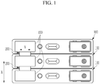
- FIG. 1 A battery module in which a plurality of unit cells 100 are connected through a bus bar 200 according to an exemplary embodiment of the present invention is illustrated in FIG. 1 , and a cross-sectional view along direction X in FIG. 1 of the bus bar 200 which electrically connects one pair of unit cells 100 to each other according to an exemplary embodiment of the present invention is illustrated in FIG. 2 .
- a battery module includes: a plurality of unit cells 100 including a case 120 and an electrode terminal 150 which is protruded from the case 120; and a bus bar 200 which electrically connects any one pair of unit cells 100 among the plurality of unit cells 100.
- the bus bar 200 includes a terminal coupling unit 220 which is inserted between respective electrode terminals 150 of the pair of unit cells 100, and a case coupling unit 240 which is inserted between respective cases 120 of the pair of unit cells 100.
- the unit cell 100 of the present invention may include various types of unit cells, it may preferably include a rechargeable battery which can be charged and discharged.
- the unit cell 100 includes the case 120, and an electrode assembly 110 including an anode, a cathode, and a separator may be accommodated within the case 120.
- the electrode assembly 110 may be formed in a wound shape, a stacked shape, or the like, and the case 120 may be formed in various shapes as necessary.
- the case 120 may have an open shape formed in one surface thereof to accommodate the electrode assembly 110, and a cap plate may be coupled to the open surface of the case 120.
- the unit cell 100 includes electrode terminals 150 which are protruded from the case 120, and the electrode terminals 150 may be installed at various positions including the cap plate and the like as necessary.
- One pair of electrode terminals 150 may be provided for each of the unit cells 100, and the one pair of electrode terminals 150 may each be electrically connected to a cathode and an anode of the electrode assembly 110.
- the bus bar 200 electrically connects any one pair of unit cells 100 among a plurality of unit cells 100 to each other.
- the one pair of unit cells 100 are disposed to be adjacent to each other, and the bus bar 200 may be formed such that the electrode terminals 150 which are each installed at the one pair of unit cells 100 are electrically connected to each other.
- FIG. 2 illustrates a cross-section of the one pair of unit cells 100 and a bus bar 200 which is inserted between the one pair of unit cells 100.
- the bus bar 200 includes the terminal coupling unit 220 which is inserted between electrode terminals 150 which are each formed in the one pair of unit cells 100, and includes the case coupling unit 240 which is inserted between cases 120 which are formed in the one pair of unit cells 100.
- the bus bar 200 is physically coupled or electrically connected to the electrode terminals 150 of the unit cells 100, and may be formed of a conductive material such that the bus bar 200 electrically connects between the unit cells 100.
- the terminal coupling unit 220 of the bus bar 200 may be formed to be inserted between the electrode terminals 150 provided in the unit cells 100 that are different from each other such that the terminal coupling unit 220 is brought into contact with the electrode terminals 150.
- the one adjacent pair of unit cells 100 may have their electrode terminals 150 electrically connected to each other by the terminal coupling unit 220.
- FIGS. 1 to 2 illustrate a bus bar 200 of a form which has a tetragonal cross-section and of which both ends portions along a width direction X of the case 120 are brought into contact with the electrode terminal 150 according to an exemplary embodiment of the present invention.
- case coupling unit 240 may be coupled to or integrally formed with the terminal coupling unit 220, and may be inserted between respective cases 120 of the one pair of adjacent unit cells 100. Both surfaces of the case coupling unit 240 along the width direction X of the case 120 may be contacted with and supported by the case 120.
- a unit cell 100 may have the electrode terminal 150 formed on a top surface thereof, and the terminal coupling unit 220 may be formed in a longitudinal direction parallel to the width direction X of the case 120 in a battery module according to an exemplary embodiment of the present invention.
- the case coupling unit 240 may be formed such that it is protruded in a downward direction Z from the terminal coupling unit 220, or may have various shapes. However, the case coupling unit 240 may be formed in a square pillar shape having a square or rectangular cross-section as illustrated in FIG. 2 .
- the case 120 may be electrically connected to a cathode or an anode of the electrode assembly 110.
- the case coupling unit 240 and the terminal coupling unit 220 are formed of a conductive material, and may be provided to electrically connect the adjacent unit cells 100 in a state that the case coupling unit 240 and the terminal coupling unit 220 are brought into contact with each case 120 of adjacent unit cells 100. Accordingly, the case coupling unit 240 together with the terminal coupling unit 220 can increase an electrical connection area.
- the bus bar 200 including the terminal coupling unit 220 and a case coupling unit 240 is inserted between adjacent unit cells 100 such that the bus bar 200 is brought into contact with and electrically connected to the adjacent unit cells 100. Therefore, an additional coupling member is not required in coupling of the bus bar 200.
- the plurality of unit cells 100 in a battery module according to an exemplary embodiment of the present invention are arranged along a width direction X of the case 120, the terminal coupling unit 220 is extended along an arrangement direction of the plurality of unit cells 100, both end portions of the terminal coupling unit 220 are brought into contact with each electrode terminal 150 of the one pair of unit cells 100, the case coupling unit 240 is extended from the terminal coupling unit 220, and both surfaces of the case coupling unit 240 may be brought into contact with each case 120 of the one pair of unit cells 100.
- FIG. 2 illustrates a state in which a bus bar 200 including the terminal coupling unit 220 and the case coupling unit 240 having the above-described shapes is inserted into one pair of unit cells 100.
- the electrode terminal 150 in a battery module has an insertion groove 155 formed in surfaces thereof facing the terminal coupling unit 220 such that the terminal coupling unit 220 is inserted into and coupled to the insertion groove 155, one surface of the insertion groove 155 which is at the side of a longitudinal direction Y of the case 120 is open, and the terminal coupling unit 220 is slid along the longitudinal direction Y of the case 120 such that the terminal coupling unit 220 may be inserted into the insertion groove 155.
- the electrode terminal 150 in an exemplary embodiment of the present invention may have the insertion groove 155 formed in surfaces thereof which face the terminal coupling unit 220, the insertion groove 155 is formed to be recessed along the width direction X of the case 120, and one surface of the insertion groove 155 along the longitudinal direction Y of the case 120 may be open.
- the bus bar 200 may be slid and inserted between one pair of unit cells 100 adjacent along the longitudinal direction Y of the case 120.
- the bus bar 200 may be formed such that the thickness of the bus bar 200 corresponds to that of the insertion groove 155, and both end portions of the bus bar 200 are inserted into and brought into contact with the insertion groove 155 of the electrode terminals 150 which face each other such that both end portions of the bus bar 200 are electrically connected to the insertion groove 155 of the electrode terminals 150.
- the case 120 in a battery module according to an exemplary embodiment of the present invention may have a stepped groove 125 formed in one surface thereof facing the case coupling unit 240 such that the case coupling unit 240 is inserted into the stepped groove 125.
- the case 120 may have the stepped groove 125 formed in one surface thereof facing the case coupling unit 240 of the bus bar 200, the stepped groove 125 is recessed along the width direction X of the case 120, and one surface of the stepped groove 125 along the longitudinal direction Y of the case 120 may be open.
- the insertion groove 155 and the stepped groove 125 have their outer surfaces open along the longitudinal direction Y of the case 120, and the bus bar 200 is slid along the longitudinal direction Y of the case 120 such that the terminal coupling unit 220 is inserted into the insertion groove 155 and the case coupling unit 240 is inserted into and mounted on the stepped groove 125 at the same time.
- the bus bar 200 may be stably inserted between adjacent unit cells 100 and may maintain a stable contact state between the adjacent unit cells 100.
- FIG. 3 is a drawing showing a perspective view of a bus bar 200 in a battery module according to an exemplary embodiment of the present invention.
- the case coupling unit 240 may have an internal space 205 formed therein to absorb a separation distance change of the one pair of unit cells 100.
- FIGS. 2 and 3 illustrate a case coupling unit 240 in which the internal space 205 is formed according to an exemplary embodiment of the present invention.
- the step coupling unit and the case coupling unit 240 may have a common internal space 205 formed therein as illustrated in FIGS. 2 and 3 .
- the case coupling unit 240 which is inserted to be in surface contact with respective cases 120 of adjacent unit cells 100, may have an internal space 205 formed therein to absorb a thickness change or an external impact due to swelling of the unit cells 100.
- a swelling phenomenon of the unit cells 100 may be generated due to various reasons in the operation situation of a battery module. Thickness variation of the unit cells 100 may be generated under the swelling circumstances in which volume of the case 120 is expanded by an increase in internal pressure of the unit cell 100.
- the case coupling unit 240 in an exemplary embodiment of the present invention has the internal space 205 formed therein such that the case coupling unit 240 is formed to have a varied thickness according to an external pressure, thereby effectively coping with swelling of the unit cell 100, and further providing a buffer space for absorbing an external impact.
- a bus bar 200 of a battery module includes the terminal coupling unit 220 and the case coupling unit 240 which are formed by bending a single conductive member, and both surfaces of the bus bar 200 may be open along the longitudinal direction Y of the case 120.
- the bus bar 200 may be formed by bending a plate-shaped member made of metal several times. That is, the bus bar 200 is integrally composed of the terminal coupling unit 220 and the case coupling unit 240, and may be formed in the form of a clip by bending a single conductive member several times.
- the bus bar 200 which is formed by bending a single member according to an exemplary embodiment of the present invention may be formed with a hollow form having the internal space 205 formed therein, and may be formed such that both surfaces of the bus bar 200 are open along the longitudinal direction Y of the case 120.
- the bus bar 200 is advantageous for allowing a thickness variation thereof and enabling it to be elastically compressed and restored when swelling of the unit cell 100 is generated by forming the bus bar 200 by bending the single member such that the internal space 205 is formed therein. Moreover, since the bus bar 200 has a shape of which both surfaces thereof are opened along the longitudinal direction Y of the case 120, compression and restoration of the bus bar 200 according to an external pressure may easily occur.
- the case coupling unit 240 in a battery module according to an exemplary embodiment of the present invention is extended from the terminal coupling unit 220, and an end portion 245 of the case coupling unit 240 may be opened such that the internal space 205 is exposed to the outside.
- the bus bar 200 illustrated in FIGS. 2 and 3 is formed by protruding the case coupling unit 240 in a downward direction of the terminal coupling unit 220, and the end portion 245 of the case coupling unit 240 has an opened shape.
- the case coupling unit 240 of which the internal space 205 is exposed from the opened end portion 245 to the outside has a free end formed in lower end portions of both surfaces thereof that are brought into contact with the case 120.
- the case coupling unit 240 which is compressed in the width direction X of the case 120 according to generation of swelling or the like of the unit cell 100 facilitates displacement due to compression by forming the free end in the lower end portions of both surfaces of the case coupling unit 240. Accordingly, a thickness variation of the unit cell 100 due to swelling or the like effectively occurs.
- an insulating member 250 having elasticity may be provided in the internal space 205 of the case coupling unit 240 in the bus bar 200 illustrated in FIGS. 2 and 3 .
- the insulating member 250 may be formed of materials such as rubber or urethane which have high elastic modulus.
- the case coupling unit 240 according to an exemplary embodiment of the present invention has the insulating member 250 having elasticity formed therein. Therefore, the case coupling unit 240 can maintain a state in which both surfaces of the case coupling unit 240 are stably closely adhered to the case 120 of the unit cell 100 by elasticity of the insulating member 250 even when the case coupling unit 240 returns to the normal state after a separation distance between the unit cells 100 is reduced according to the generation of swelling.
- the insulating member 250 may be formed of various materials, and the insulating member 250 may be provided such that the insulating member 250 is closely adhered to and supported by an inner surface of the case coupling unit 240 in the internal space 205 of the case coupling unit 240.
- the shape of the insulating member 250 may include a shape which is formed by the internal space 205 of the case coupling unit 240 or shapes that are diversely determined as needed.
Landscapes
- Chemical & Material Sciences (AREA)
- Chemical Kinetics & Catalysis (AREA)
- Electrochemistry (AREA)
- General Chemical & Material Sciences (AREA)
- Connection Of Batteries Or Terminals (AREA)
- Battery Mounting, Suspending (AREA)
Abstract
Description
- The present invention relates to a battery module, and more specifically, to a battery module which connects a plurality of secondary unit cells each including an electrode terminal coupled to a bus bar.
- A rechargeable battery is a battery which repeatedly performs charge and discharge, differently from a primary battery. A small capacity rechargeable battery is used in a portable small electronic device such as a mobile phone, a notebook computer, or a camcorder, and a large capacity rechargeable battery may be used as a power supply for driving a motor for a hybrid vehicle or an electric vehicle.
- The rechargeable battery may be used as a single cell as in a small electronic device, or may be used in a module state in which a plurality of unit cells are electrically connected as in the power supply for driving the motor. A battery module in which unit cells are used as rechargeable batteries and include a plurality of unit cells includes a bus bar which enables the plurality of unit cells to be electrically connected to one another.
- The bus bar may be coupled to an electrode terminal of the unit cells, and may have various coupling methods. Resistance or the like may be different according to a coupling method of the unit cells and the bus bar.
- Further, when swelling occurs in the unit cells, a separation distance between electrode terminals provided in the plurality of unit cells may vary. When the bus bar is coupled to the electrode terminals which are provided in each of the plurality of unit cells, tension or the like may be formed in the bus bar according to a change in the separation distance such that damage to the bus bar may occur. Therefore, it is important to effectively cope with this.
- The above information disclosed in this Background section is only for enhancement of understanding of the background of the invention and therefore it may contain information that does not form the prior art that is already known in this country to a person of ordinary skill in the art.
- The present invention provides a battery module which minimizes an additional configurations for coupling a bus bar, implements stable coupling of the bus bar, and can effectively respond to swelling of the unit cells.
- A battery module according to an exemplary embodiment of the present invention includes: a plurality of unit cells including a case and electrode terminals which are protruded from the case; and a bus bar which electrically connects any one pair of unit cells among the plurality of unit cells, wherein the bus bar includes: a terminal coupling unit which is inserted between respective electrode terminals of the one pair of unit cells; and a case coupling unit which is inserted between respective cases of the one pair of unit cells.
- The electrode terminal and the case may have the same polarity.
- The plurality of unit cells are arranged along a width direction of the cases. The terminal coupling unit is extended along an arrangement direction of the plurality of unit cells, and both end portions of the terminal coupling unit are brought into contact with respective electrode terminals of the one pair of unit cells. The case coupling unit is extended from the terminal coupling unit, and both surfaces of the case coupling unit may be brought into contact with respective cases of the one pair of unit cells.
- The electrode terminal has an insertion groove formed in one surface thereof facing the terminal coupling unit such that the terminal coupling unit is inserted into and coupled to the insertion groove, one surface of the insertion groove at a longitudinal directional side of the case is open, and the terminal coupling unit is slid along a longitudinal direction of the case such that the terminal coupling unit may be inserted into the insertion groove.
- The case may have a stepped groove formed in one surface thereof facing the case coupling unit such that the case coupling unit is inserted into the stepped groove.
- The case coupling unit may have an internal space formed therein to absorb a separation distance change of the one pair of unit cells.
- The bus bar includes the terminal coupling unit and the case coupling unit which are formed by a single bent conductive member, and both surfaces of the bus bar may be open along a longitudinal direction of the case.
- The case coupling unit is extended from the terminal coupling unit, and an end portion of the case coupling unit may be open such that the internal space is exposed to the outside.
- The internal space of the case coupling unit may have an insulating member with elasticity formed therein.
- Exemplary embodiments of the present invention can minimize additional configurations for coupling the bus bar, can implement stable coupling of the bus bar, and can effectively correspond to swelling of the unit cells.
-
-
FIG. 1 is a drawing showing a battery module according to an exemplary embodiment of the present invention. -
FIG. 2 is a drawing showing a cross-section of one pair of unit cells and a bus bar in a battery module along direction X inFIG. 1 according to an exemplary embodiment of the present invention. -
FIG. 3 is a perspective view of a bus bar which is formed in a battery module according to an exemplary embodiment of the present invention. - Hereinafter, the embodiments of the present invention will be described in detail with reference to the accompanying drawings so that the present invention can be easily realized by those skilled in the art.
- However, the present invention can be implemented in various different forms and is not limited to the embodiments described herein. In the drawings, parts that are irrelevant to the description are omitted for simplicity of explanation, and like reference numerals denote like parts through the entire document.
- In the present specification, repeated descriptions of the same elements will be omitted.
- Further, in the present specification, if it is mentioned that an element is "coupled" or "connected" to another element, it should be understood that the element is directly coupled or connected to another element or still another element is interposed therebetween. On the contrary, in the present specification, if it is mentioned that an element is "directly coupled" or "directly connected" to another element, it should be understood that no other element is interposed therebetween.
- Further, the terms used in the present specification are merely used to describe particular embodiments, and are not intended to limit the present invention.
- In addition, an expression of the singular form in the present specification will cover an expression in the plural form unless otherwise obviously indicated from the context.
- In the present specification, it should be understood that the word "include" or "has" indicates that a feature, a number, a step, an operation, a component, a part, or a combination thereof described in the specification is present, but does not exclude the possibility of presence or addition of one or more other features, numbers, steps, operations, components, parts, or combinations thereof, in advance.
- In the present specification, a term "and/or" includes a combination of multiple described items or any one of the multiple described items. In the present specification, "A or B" may include "A", "B", or "both A and B".
- A battery module in which a plurality of
unit cells 100 are connected through abus bar 200 according to an exemplary embodiment of the present invention is illustrated inFIG. 1 , and a cross-sectional view along direction X inFIG. 1 of thebus bar 200 which electrically connects one pair ofunit cells 100 to each other according to an exemplary embodiment of the present invention is illustrated inFIG. 2 . - As illustrated in
FIGS. 1 and2 , a battery module according to an exemplary embodiment of the present invention includes: a plurality ofunit cells 100 including acase 120 and anelectrode terminal 150 which is protruded from thecase 120; and abus bar 200 which electrically connects any one pair ofunit cells 100 among the plurality ofunit cells 100. - Further, the
bus bar 200 includes aterminal coupling unit 220 which is inserted betweenrespective electrode terminals 150 of the pair ofunit cells 100, and acase coupling unit 240 which is inserted betweenrespective cases 120 of the pair ofunit cells 100. - Although the
unit cell 100 of the present invention may include various types of unit cells, it may preferably include a rechargeable battery which can be charged and discharged. Theunit cell 100 includes thecase 120, and anelectrode assembly 110 including an anode, a cathode, and a separator may be accommodated within thecase 120. - The
electrode assembly 110 may be formed in a wound shape, a stacked shape, or the like, and thecase 120 may be formed in various shapes as necessary. Thecase 120 may have an open shape formed in one surface thereof to accommodate theelectrode assembly 110, and a cap plate may be coupled to the open surface of thecase 120. - Meanwhile, the
unit cell 100 includeselectrode terminals 150 which are protruded from thecase 120, and theelectrode terminals 150 may be installed at various positions including the cap plate and the like as necessary. One pair ofelectrode terminals 150 may be provided for each of theunit cells 100, and the one pair ofelectrode terminals 150 may each be electrically connected to a cathode and an anode of theelectrode assembly 110. - The
bus bar 200 electrically connects any one pair ofunit cells 100 among a plurality ofunit cells 100 to each other. The one pair ofunit cells 100 are disposed to be adjacent to each other, and thebus bar 200 may be formed such that theelectrode terminals 150 which are each installed at the one pair ofunit cells 100 are electrically connected to each other. - Although a plurality of
unit cells 100 in a battery module according to an exemplary embodiment of the present invention may be arranged along a width direction X of thecase 120 as illustrated inFIG. 1 , the plurality ofunit cells 100 may be arranged in various directions as necessary. - The
bus bar 200 is inserted between one adjacent pair ofunit cells 100.FIG. 2 illustrates a cross-section of the one pair ofunit cells 100 and abus bar 200 which is inserted between the one pair ofunit cells 100. - The
bus bar 200 includes theterminal coupling unit 220 which is inserted betweenelectrode terminals 150 which are each formed in the one pair ofunit cells 100, and includes thecase coupling unit 240 which is inserted betweencases 120 which are formed in the one pair ofunit cells 100. - Preferably, the
bus bar 200 is physically coupled or electrically connected to theelectrode terminals 150 of theunit cells 100, and may be formed of a conductive material such that thebus bar 200 electrically connects between theunit cells 100. - As illustrated in
FIG. 2 , theterminal coupling unit 220 of thebus bar 200 may be formed to be inserted between theelectrode terminals 150 provided in theunit cells 100 that are different from each other such that theterminal coupling unit 220 is brought into contact with theelectrode terminals 150. The one adjacent pair ofunit cells 100 may have theirelectrode terminals 150 electrically connected to each other by theterminal coupling unit 220. - The
terminal coupling unit 220 may be formed such that theterminal coupling unit 220 is brought into contact with surfaces of theelectrode terminals 150 that face each other. Accordingly, theterminal coupling unit 220 can implement an effective electrical connection state while minimizing its volume without being protruded to the outside of theelectrode terminal 150. - A portion of the
terminal coupling unit 220 which is brought into contact with theelectrode terminal 150 may have a diversely variable shape according to a shape of theelectrode terminal 150.FIGS. 1 to 2 illustrate abus bar 200 of a form which has a tetragonal cross-section and of which both ends portions along a width direction X of thecase 120 are brought into contact with theelectrode terminal 150 according to an exemplary embodiment of the present invention. - On the other hand, the
case coupling unit 240 may be coupled to or integrally formed with theterminal coupling unit 220, and may be inserted betweenrespective cases 120 of the one pair ofadjacent unit cells 100. Both surfaces of thecase coupling unit 240 along the width direction X of thecase 120 may be contacted with and supported by thecase 120. - As illustrated in
FIGS. 1 and2 , aunit cell 100 may have theelectrode terminal 150 formed on a top surface thereof, and theterminal coupling unit 220 may be formed in a longitudinal direction parallel to the width direction X of thecase 120 in a battery module according to an exemplary embodiment of the present invention. - The
case coupling unit 240 may be formed such that it is protruded in a downward direction Z from theterminal coupling unit 220, or may have various shapes. However, thecase coupling unit 240 may be formed in a square pillar shape having a square or rectangular cross-section as illustrated inFIG. 2 . - The
bus bar 200 may be structurally stably arranged between one pair ofunit cells 100 by thecase coupling unit 240. In addition, thecase coupling unit 240 may have aninternal space 205 formed therein, or may be formed to have elasticity such that thecase coupling unit 240 absorbs an impact or the like transmitted from the outside of the battery module. Moreover, thecase coupling unit 240 may be formed to absorb a thickness change according to swelling occurring in therespective unit cells 100. - The
case 120 may be electrically connected to a cathode or an anode of theelectrode assembly 110. Thecase coupling unit 240 and theterminal coupling unit 220 are formed of a conductive material, and may be provided to electrically connect theadjacent unit cells 100 in a state that thecase coupling unit 240 and theterminal coupling unit 220 are brought into contact with eachcase 120 ofadjacent unit cells 100. Accordingly, thecase coupling unit 240 together with theterminal coupling unit 220 can increase an electrical connection area. - Moreover, the
bus bar 200 including theterminal coupling unit 220 and acase coupling unit 240 is inserted betweenadjacent unit cells 100 such that thebus bar 200 is brought into contact with and electrically connected to theadjacent unit cells 100. Therefore, an additional coupling member is not required in coupling of thebus bar 200. - Therefore, a configuration can be simplified. Furthermore, electrical connectivity can be effectively improved by adding a coupling member such as a bolt or the like, thereby minimizing a resistance increase in the electrical connection of the
bus bar 200 and theunit cells 100. - Meanwhile, each of the unit cells in a battery module according to an exemplary embodiment of the present invention may include the
electrode terminal 150 and thecase 120 having the same polarity. That is, theelectrode terminal 150 together with thecase 120 to which thebus bar 200 is coupled may be electrically connected to any one of a cathode and an anode in theelectrode assembly 110. - Since the
bus bar 200 has a structure in which theterminal coupling unit 220 and thecase coupling unit 240 are closely adhered and electrically connected to theelectrode terminal 150 and thecase 120 of theunit cell 100, thebus bar 200 lowers resistance by effectively increasing an area of thebus bar 200 contacting theunit cell 100, and can effectively improve electrical connection performance thereof. - On the other hand, as illustrated in
FIG. 2 , the plurality ofunit cells 100 in a battery module according to an exemplary embodiment of the present invention are arranged along a width direction X of thecase 120, theterminal coupling unit 220 is extended along an arrangement direction of the plurality ofunit cells 100, both end portions of theterminal coupling unit 220 are brought into contact with eachelectrode terminal 150 of the one pair ofunit cells 100, thecase coupling unit 240 is extended from theterminal coupling unit 220, and both surfaces of thecase coupling unit 240 may be brought into contact with eachcase 120 of the one pair ofunit cells 100. - According to an exemplary embodiment of the present invention, the
terminal coupling unit 220 may be formed in a shape that is extended along an arrangement direction of theunit cells 100 as illustrated inFIG. 2 , i.e., the width direction X of thecase 120. Both end portions of theterminal coupling unit 220 along the width direction X of thecase 120 are brought into contact with and electrically connected to electrodeterminals 150 which face each other. - The
case coupling unit 240 may be preferably extended in a downward direction of theterminal coupling unit 220, and both surfaces of thecase coupling unit 240 along the width direction X of thecase 120 may be brought into contact with thecases 120 which face each other. -
FIG. 2 illustrates a state in which abus bar 200 including theterminal coupling unit 220 and thecase coupling unit 240 having the above-described shapes is inserted into one pair ofunit cells 100. - Meanwhile, as illustrated in
FIG. 2 , theelectrode terminal 150 in a battery module according to an exemplary embodiment of the present invention has aninsertion groove 155 formed in surfaces thereof facing theterminal coupling unit 220 such that theterminal coupling unit 220 is inserted into and coupled to theinsertion groove 155, one surface of theinsertion groove 155 which is at the side of a longitudinal direction Y of thecase 120 is open, and theterminal coupling unit 220 is slid along the longitudinal direction Y of thecase 120 such that theterminal coupling unit 220 may be inserted into theinsertion groove 155. - Specifically, the
electrode terminal 150 in an exemplary embodiment of the present invention may have theinsertion groove 155 formed in surfaces thereof which face theterminal coupling unit 220, theinsertion groove 155 is formed to be recessed along the width direction X of thecase 120, and one surface of theinsertion groove 155 along the longitudinal direction Y of thecase 120 may be open. - The one open surface of the
insertion groove 155 may be one surface of theinsertion groove 155 facing the center of thecase 120, or the opposite surface thereof, and both surfaces of theinsertion groove 155 may be open. - The
bus bar 200 may be slid and inserted between one pair ofunit cells 100 adjacent along the longitudinal direction Y of thecase 120. Thebus bar 200 may be formed such that the thickness of thebus bar 200 corresponds to that of theinsertion groove 155, and both end portions of thebus bar 200 are inserted into and brought into contact with theinsertion groove 155 of theelectrode terminals 150 which face each other such that both end portions of thebus bar 200 are electrically connected to theinsertion groove 155 of theelectrode terminals 150. - On the other hand, as illustrated in
FIG. 2 , thecase 120 in a battery module according to an exemplary embodiment of the present invention may have a steppedgroove 125 formed in one surface thereof facing thecase coupling unit 240 such that thecase coupling unit 240 is inserted into the steppedgroove 125. - The
case 120 may have the steppedgroove 125 formed in one surface thereof facing thecase coupling unit 240 of thebus bar 200, the steppedgroove 125 is recessed along the width direction X of thecase 120, and one surface of the steppedgroove 125 along the longitudinal direction Y of thecase 120 may be open. - One surface of the stepped
groove 125 is open to be exposed to the outside of theunit cell 100, and thecase coupling unit 240 together with theterminal coupling unit 220 may be slid and inserted betweenrespective cases 120 ofunit cells 100 adjacent along the longitudinal direction Y of thecase 120. - That is, the
insertion groove 155 and the steppedgroove 125 have their outer surfaces open along the longitudinal direction Y of thecase 120, and thebus bar 200 is slid along the longitudinal direction Y of thecase 120 such that theterminal coupling unit 220 is inserted into theinsertion groove 155 and thecase coupling unit 240 is inserted into and mounted on the steppedgroove 125 at the same time. - Accordingly, as the stepped
groove 125 in addition to theinsertion groove 155 is formed, thebus bar 200 may be stably inserted betweenadjacent unit cells 100 and may maintain a stable contact state between theadjacent unit cells 100. -
FIG. 3 is a drawing showing a perspective view of abus bar 200 in a battery module according to an exemplary embodiment of the present invention. In an exemplary embodiment of the present invention, thecase coupling unit 240 may have aninternal space 205 formed therein to absorb a separation distance change of the one pair ofunit cells 100. -
FIGS. 2 and3 illustrate acase coupling unit 240 in which theinternal space 205 is formed according to an exemplary embodiment of the present invention. In an exemplary embodiment of the present invention, the step coupling unit and thecase coupling unit 240 may have a commoninternal space 205 formed therein as illustrated inFIGS. 2 and3 . - The
case coupling unit 240, which is inserted to be in surface contact withrespective cases 120 ofadjacent unit cells 100, may have aninternal space 205 formed therein to absorb a thickness change or an external impact due to swelling of theunit cells 100. - A swelling phenomenon of the
unit cells 100 may be generated due to various reasons in the operation situation of a battery module. Thickness variation of theunit cells 100 may be generated under the swelling circumstances in which volume of thecase 120 is expanded by an increase in internal pressure of theunit cell 100. - When swelling of the
unit cell 100 is generated in an exemplary embodiment of the present invention, thecase coupling unit 240 may have a reduced thickness by forming theinternal space 205 in thecase coupling unit 240 of abus bar 200 which is coupled to theunit cell 100 that is expanded by swelling such that thecase coupling unit 240 is compressed as much as a thickness increment of thecase 120. - That is, the
case coupling unit 240 in an exemplary embodiment of the present invention has theinternal space 205 formed therein such that thecase coupling unit 240 is formed to have a varied thickness according to an external pressure, thereby effectively coping with swelling of theunit cell 100, and further providing a buffer space for absorbing an external impact. - On the other hand, as illustrated in
FIG. 3 , abus bar 200 of a battery module according to an exemplary embodiment of the present invention includes theterminal coupling unit 220 and thecase coupling unit 240 which are formed by bending a single conductive member, and both surfaces of thebus bar 200 may be open along the longitudinal direction Y of thecase 120. - The
bus bar 200 may be formed by bending a plate-shaped member made of metal several times. That is, thebus bar 200 is integrally composed of theterminal coupling unit 220 and thecase coupling unit 240, and may be formed in the form of a clip by bending a single conductive member several times. - The
bus bar 200 which is formed by bending a single member according to an exemplary embodiment of the present invention may be formed with a hollow form having theinternal space 205 formed therein, and may be formed such that both surfaces of thebus bar 200 are open along the longitudinal direction Y of thecase 120. - The
bus bar 200 is advantageous for allowing a thickness variation thereof and enabling it to be elastically compressed and restored when swelling of theunit cell 100 is generated by forming thebus bar 200 by bending the single member such that theinternal space 205 is formed therein. Moreover, since thebus bar 200 has a shape of which both surfaces thereof are opened along the longitudinal direction Y of thecase 120, compression and restoration of thebus bar 200 according to an external pressure may easily occur. - Meanwhile, as illustrated in
FIGS. 2 and3 , thecase coupling unit 240 in a battery module according to an exemplary embodiment of the present invention is extended from theterminal coupling unit 220, and anend portion 245 of thecase coupling unit 240 may be opened such that theinternal space 205 is exposed to the outside. - The
bus bar 200 illustrated inFIGS. 2 and3 is formed by protruding thecase coupling unit 240 in a downward direction of theterminal coupling unit 220, and theend portion 245 of thecase coupling unit 240 has an opened shape. Thecase coupling unit 240 of which theinternal space 205 is exposed from the openedend portion 245 to the outside has a free end formed in lower end portions of both surfaces thereof that are brought into contact with thecase 120. - Therefore, the
case coupling unit 240 which is compressed in the width direction X of thecase 120 according to generation of swelling or the like of theunit cell 100 facilitates displacement due to compression by forming the free end in the lower end portions of both surfaces of thecase coupling unit 240. Accordingly, a thickness variation of theunit cell 100 due to swelling or the like effectively occurs. - Further, an insulating
member 250 having elasticity may be provided in theinternal space 205 of thecase coupling unit 240 in thebus bar 200 illustrated inFIGS. 2 and3 . The insulatingmember 250 may be formed of materials such as rubber or urethane which have high elastic modulus. Thecase coupling unit 240 according to an exemplary embodiment of the present invention has the insulatingmember 250 having elasticity formed therein. Therefore, thecase coupling unit 240 can maintain a state in which both surfaces of thecase coupling unit 240 are stably closely adhered to thecase 120 of theunit cell 100 by elasticity of the insulatingmember 250 even when thecase coupling unit 240 returns to the normal state after a separation distance between theunit cells 100 is reduced according to the generation of swelling. - The insulating
member 250 may be formed of various materials, and the insulatingmember 250 may be provided such that the insulatingmember 250 is closely adhered to and supported by an inner surface of thecase coupling unit 240 in theinternal space 205 of thecase coupling unit 240. The shape of the insulatingmember 250 may include a shape which is formed by theinternal space 205 of thecase coupling unit 240 or shapes that are diversely determined as needed. - Although the present invention has been illustrated and described in association with certain embodiments, it will be apparent to those skilled in the art that the present invention may be diversely modified and changed within the technical scope of the present invention provided by the following claims.
-
- 100:
- Unit cell
- 110:
- Electrode assembly
- 120:
- Case
- 125:
- Stepped groove
- 150:
- Electrode terminal
- 155:
- Insertion groove
- 200:
- Bus bar
- 205:
- Internal space
- 220:
- Terminal coupling unit
- 240:
- Case coupling unit
- 250:
- Insulating member
Claims (9)
- A battery module including:a plurality of unit cells (100) including a case (120) and electrode terminals (150) which are protruded from the case (120); anda bus bar (200) which electrically connects one pair of adjacent unit cells (100) among the plurality of unit cells (100), whereinthe bus bar (200) includes:a terminal coupling unit (220) which is inserted between respective electrode terminals (150) of the one pair of unit cells (100); anda case coupling unit (240) which is inserted between respective cases (120) of the one pair of unit cells (100).
- The battery module of claim 1, wherein
the electrode terminal (150) and the case (120) have the same polarity. - The battery module of claim 1 or 2, wherein
the plurality of unit cells (100) are arranged along a width direction (X) of the cases (120),
the terminal coupling unit (220) is extended along an arrangement direction (X) of the plurality of unit cells (100), while both end portions of the terminal coupling unit (220) are brought into contact with respective electrode terminals (150) of the one pair of unit cells (100), and
the case coupling unit (240) is extended from the terminal coupling unit (220), and both surfaces of the case coupling unit (240) are brought into contact with respective cases (120) of the one pair of unit cells (100). - The battery module of one of the preceding claims, wherein
the electrode terminal (150) has an insertion groove (155) formed in one surface thereof facing the terminal coupling unit (220) such that the terminal coupling unit (220) is inserted into and coupled to the insertion groove (155),
one surface of the insertion groove (155) at a longitudinal directional side of the case (120) is open, and
the terminal coupling unit (220) is adapted to be slid along a longitudinal direction (Y) of the case (120) such that the terminal coupling unit (220) is inserted into the insertion groove (155). - The battery module of one of the preceding claims, wherein
the case (120) has a stepped groove (125) formed in one surface thereof facing the case coupling unit (240) such that the case coupling unit (240) is inserted into the stepped groove (125). - The battery module of one of the preceding claims, wherein
the case coupling unit (240) has an internal space (205) formed therein to absorb a separation distance change of the one pair of unit cells (100). - The battery module of one of the preceding claims, wherein
the bus bar (200) includes the terminal coupling unit (220) and the case coupling unit (240) which are formed by bending a single conductive member, and both surfaces of the bus bar are open along a longitudinal direction (Y) of the case (120). - The battery module of one of claims 6 and 7, wherein
the case coupling unit (240) is extended from the terminal coupling unit (220) and an end portion (245) of the case coupling unit (240) is open such that the internal space (205) is exposed to the outside. - The battery module of claim 8, wherein
the internal space of the case coupling unit has an elastic insulating member (250) formed therein.
Applications Claiming Priority (1)
| Application Number | Priority Date | Filing Date | Title |
|---|---|---|---|
| KR1020180067516A KR102598260B1 (en) | 2018-06-12 | 2018-06-12 | Battery module |
Publications (2)
| Publication Number | Publication Date |
|---|---|
| EP3582292A1 true EP3582292A1 (en) | 2019-12-18 |
| EP3582292B1 EP3582292B1 (en) | 2023-08-02 |
Family
ID=66668816
Family Applications (1)
| Application Number | Title | Priority Date | Filing Date |
|---|---|---|---|
| EP19176973.6A Active EP3582292B1 (en) | 2018-06-12 | 2019-05-28 | Battery module |
Country Status (6)
| Country | Link |
|---|---|
| US (1) | US11196127B2 (en) |
| EP (1) | EP3582292B1 (en) |
| KR (1) | KR102598260B1 (en) |
| CN (1) | CN110600665B (en) |
| HU (1) | HUE063453T2 (en) |
| PL (1) | PL3582292T3 (en) |
Cited By (1)
| Publication number | Priority date | Publication date | Assignee | Title |
|---|---|---|---|---|
| EP4421969A4 (en) * | 2022-06-16 | 2025-07-16 | Lg Energy Solution Ltd | SECONDARY BATTERY WITH IMPROVED CONNECTION STRUCTURE |
Families Citing this family (2)
| Publication number | Priority date | Publication date | Assignee | Title |
|---|---|---|---|---|
| CN112038521B (en) * | 2020-08-18 | 2024-10-29 | 嘉兴模度新能源有限公司 | Battery module with batteries arranged in same direction and connected in series in rows |
| JP2025108124A (en) * | 2024-01-10 | 2025-07-23 | 矢崎総業株式会社 | Connection structure and assembly |
Citations (3)
| Publication number | Priority date | Publication date | Assignee | Title |
|---|---|---|---|---|
| US20050250006A1 (en) * | 2004-05-04 | 2005-11-10 | Yong-Sam Kim | Secondary battery module |
| US20160329544A1 (en) * | 2015-05-08 | 2016-11-10 | Byd Company Limited | Battery cell connector |
| DE102016200961A1 (en) * | 2016-01-25 | 2017-07-27 | Bayerische Motoren Werke Aktiengesellschaft | Connector system, battery module, method of forming a tap and operating device |
Family Cites Families (10)
| Publication number | Priority date | Publication date | Assignee | Title |
|---|---|---|---|---|
| JP4154136B2 (en) * | 2001-08-06 | 2008-09-24 | 松下電器産業株式会社 | Square sealed battery |
| KR100648720B1 (en) * | 2004-12-02 | 2006-11-23 | 삼성에스디아이 주식회사 | Case of secondary battery, secondary battery and secondary battery module using same |
| KR200421590Y1 (en) * | 2006-04-11 | 2006-07-13 | 송재중 | DC voltage converter with inserting printed circuit board |
| FR2979472B1 (en) | 2011-08-29 | 2013-08-23 | Batscap Sa | CONNECTOR ARRANGED BETWEEN TWO ENERGY STORAGE ASSEMBLIES |
| US20130260611A1 (en) | 2012-04-03 | 2013-10-03 | Jang-Gun Ahn | Battery module |
| KR20150069733A (en) | 2013-12-16 | 2015-06-24 | 삼성에스디아이 주식회사 | Battery Module |
| KR102221801B1 (en) * | 2014-02-04 | 2021-03-02 | 삼성에스디아이 주식회사 | Busbar module |
| KR102341402B1 (en) | 2015-05-15 | 2021-12-20 | 삼성에스디아이 주식회사 | Battery module |
| KR102449864B1 (en) | 2015-09-04 | 2022-09-30 | 현대모비스 주식회사 | Connection device for battery module assembly |
| CN107170943A (en) | 2017-07-05 | 2017-09-15 | 江西优特汽车技术有限公司 | Dividing plate and the Soft Roll electrokinetic cell with it |
-
2018
- 2018-06-12 KR KR1020180067516A patent/KR102598260B1/en active Active
-
2019
- 2019-05-20 US US16/416,643 patent/US11196127B2/en active Active
- 2019-05-21 CN CN201910423085.7A patent/CN110600665B/en active Active
- 2019-05-28 EP EP19176973.6A patent/EP3582292B1/en active Active
- 2019-05-28 HU HUE19176973A patent/HUE063453T2/en unknown
- 2019-05-28 PL PL19176973.6T patent/PL3582292T3/en unknown
Patent Citations (3)
| Publication number | Priority date | Publication date | Assignee | Title |
|---|---|---|---|---|
| US20050250006A1 (en) * | 2004-05-04 | 2005-11-10 | Yong-Sam Kim | Secondary battery module |
| US20160329544A1 (en) * | 2015-05-08 | 2016-11-10 | Byd Company Limited | Battery cell connector |
| DE102016200961A1 (en) * | 2016-01-25 | 2017-07-27 | Bayerische Motoren Werke Aktiengesellschaft | Connector system, battery module, method of forming a tap and operating device |
Cited By (1)
| Publication number | Priority date | Publication date | Assignee | Title |
|---|---|---|---|---|
| EP4421969A4 (en) * | 2022-06-16 | 2025-07-16 | Lg Energy Solution Ltd | SECONDARY BATTERY WITH IMPROVED CONNECTION STRUCTURE |
Also Published As
| Publication number | Publication date |
|---|---|
| KR20190140696A (en) | 2019-12-20 |
| PL3582292T3 (en) | 2024-01-15 |
| US20190379023A1 (en) | 2019-12-12 |
| HUE063453T2 (en) | 2024-01-28 |
| KR102598260B1 (en) | 2023-11-02 |
| CN110600665A (en) | 2019-12-20 |
| CN110600665B (en) | 2022-12-23 |
| EP3582292B1 (en) | 2023-08-02 |
| US11196127B2 (en) | 2021-12-07 |
Similar Documents
| Publication | Publication Date | Title |
|---|---|---|
| CN107851759B (en) | Battery module, battery pack including the same, and vehicle | |
| US9203065B2 (en) | Battery module | |
| CN104183809B (en) | Battery module | |
| CN103000835B (en) | Battery module | |
| US9748539B2 (en) | Battery module | |
| US9178206B2 (en) | Battery module | |
| US8338021B2 (en) | Battery module | |
| US7993774B2 (en) | Conductive plate and secondary battery pack using conductive plate | |
| US8592079B2 (en) | Rechargeable battery | |
| US20150079452A1 (en) | Battery module | |
| US20130330593A1 (en) | Rechargeable battery | |
| JP5319165B2 (en) | Battery pack and battery case | |
| EP3651236A1 (en) | Battery module and battery pack comprising same | |
| EP3582292B1 (en) | Battery module | |
| US9997809B2 (en) | Battery module | |
| US20140308569A1 (en) | Battery pack | |
| EP4080664A2 (en) | Battery module having flexible busbar | |
| JP7176816B2 (en) | battery module |
Legal Events
| Date | Code | Title | Description |
|---|---|---|---|
| PUAI | Public reference made under article 153(3) epc to a published international application that has entered the european phase |
Free format text: ORIGINAL CODE: 0009012 |
|
| STAA | Information on the status of an ep patent application or granted ep patent |
Free format text: STATUS: REQUEST FOR EXAMINATION WAS MADE |
|
| 17P | Request for examination filed |
Effective date: 20190528 |
|
| AK | Designated contracting states |
Kind code of ref document: A1 Designated state(s): AL AT BE BG CH CY CZ DE DK EE ES FI FR GB GR HR HU IE IS IT LI LT LU LV MC MK MT NL NO PL PT RO RS SE SI SK SM TR |
|
| AX | Request for extension of the european patent |
Extension state: BA ME |
|
| STAA | Information on the status of an ep patent application or granted ep patent |
Free format text: STATUS: EXAMINATION IS IN PROGRESS |
|
| 17Q | First examination report despatched |
Effective date: 20200909 |
|
| REG | Reference to a national code |
Ref legal event code: R079 Ipc: H01M0050503000 Ref country code: DE Ref legal event code: R079 Ref document number: 602019033875 Country of ref document: DE Free format text: PREVIOUS MAIN CLASS: H01M0002200000 Ipc: H01M0050503000 |
|
| GRAP | Despatch of communication of intention to grant a patent |
Free format text: ORIGINAL CODE: EPIDOSNIGR1 |
|
| STAA | Information on the status of an ep patent application or granted ep patent |
Free format text: STATUS: GRANT OF PATENT IS INTENDED |
|
| RIC1 | Information provided on ipc code assigned before grant |
Ipc: H01M 50/209 20210101ALI20230210BHEP Ipc: H01M 50/502 20210101ALI20230210BHEP Ipc: H01M 50/503 20210101AFI20230210BHEP |
|
| INTG | Intention to grant announced |
Effective date: 20230310 |
|
| GRAS | Grant fee paid |
Free format text: ORIGINAL CODE: EPIDOSNIGR3 |
|
| GRAA | (expected) grant |
Free format text: ORIGINAL CODE: 0009210 |
|
| STAA | Information on the status of an ep patent application or granted ep patent |
Free format text: STATUS: THE PATENT HAS BEEN GRANTED |
|
| AK | Designated contracting states |
Kind code of ref document: B1 Designated state(s): AL AT BE BG CH CY CZ DE DK EE ES FI FR GB GR HR HU IE IS IT LI LT LU LV MC MK MT NL NO PL PT RO RS SE SI SK SM TR |
|
| REG | Reference to a national code |
Ref country code: GB Ref legal event code: FG4D |
|
| REG | Reference to a national code |
Ref country code: CH Ref legal event code: EP |
|
| REG | Reference to a national code |
Ref country code: DE Ref legal event code: R096 Ref document number: 602019033875 Country of ref document: DE |
|
| REG | Reference to a national code |
Ref country code: IE Ref legal event code: FG4D |
|
| REG | Reference to a national code |
Ref country code: SE Ref legal event code: TRGR |
|
| REG | Reference to a national code |
Ref country code: LT Ref legal event code: MG9D |
|
| REG | Reference to a national code |
Ref country code: NL Ref legal event code: MP Effective date: 20230802 |
|
| REG | Reference to a national code |
Ref country code: AT Ref legal event code: MK05 Ref document number: 1595857 Country of ref document: AT Kind code of ref document: T Effective date: 20230802 |
|
| PG25 | Lapsed in a contracting state [announced via postgrant information from national office to epo] |
Ref country code: GR Free format text: LAPSE BECAUSE OF FAILURE TO SUBMIT A TRANSLATION OF THE DESCRIPTION OR TO PAY THE FEE WITHIN THE PRESCRIBED TIME-LIMIT Effective date: 20231103 |
|
| PG25 | Lapsed in a contracting state [announced via postgrant information from national office to epo] |
Ref country code: IS Free format text: LAPSE BECAUSE OF FAILURE TO SUBMIT A TRANSLATION OF THE DESCRIPTION OR TO PAY THE FEE WITHIN THE PRESCRIBED TIME-LIMIT Effective date: 20231202 |
|
| REG | Reference to a national code |
Ref country code: HU Ref legal event code: AG4A Ref document number: E063453 Country of ref document: HU |
|
| PG25 | Lapsed in a contracting state [announced via postgrant information from national office to epo] |
Ref country code: RS Free format text: LAPSE BECAUSE OF FAILURE TO SUBMIT A TRANSLATION OF THE DESCRIPTION OR TO PAY THE FEE WITHIN THE PRESCRIBED TIME-LIMIT Effective date: 20230802 Ref country code: PT Free format text: LAPSE BECAUSE OF FAILURE TO SUBMIT A TRANSLATION OF THE DESCRIPTION OR TO PAY THE FEE WITHIN THE PRESCRIBED TIME-LIMIT Effective date: 20231204 Ref country code: NO Free format text: LAPSE BECAUSE OF FAILURE TO SUBMIT A TRANSLATION OF THE DESCRIPTION OR TO PAY THE FEE WITHIN THE PRESCRIBED TIME-LIMIT Effective date: 20231102 Ref country code: NL Free format text: LAPSE BECAUSE OF FAILURE TO SUBMIT A TRANSLATION OF THE DESCRIPTION OR TO PAY THE FEE WITHIN THE PRESCRIBED TIME-LIMIT Effective date: 20230802 Ref country code: LV Free format text: LAPSE BECAUSE OF FAILURE TO SUBMIT A TRANSLATION OF THE DESCRIPTION OR TO PAY THE FEE WITHIN THE PRESCRIBED TIME-LIMIT Effective date: 20230802 Ref country code: LT Free format text: LAPSE BECAUSE OF FAILURE TO SUBMIT A TRANSLATION OF THE DESCRIPTION OR TO PAY THE FEE WITHIN THE PRESCRIBED TIME-LIMIT Effective date: 20230802 Ref country code: IS Free format text: LAPSE BECAUSE OF FAILURE TO SUBMIT A TRANSLATION OF THE DESCRIPTION OR TO PAY THE FEE WITHIN THE PRESCRIBED TIME-LIMIT Effective date: 20231202 Ref country code: HR Free format text: LAPSE BECAUSE OF FAILURE TO SUBMIT A TRANSLATION OF THE DESCRIPTION OR TO PAY THE FEE WITHIN THE PRESCRIBED TIME-LIMIT Effective date: 20230802 Ref country code: GR Free format text: LAPSE BECAUSE OF FAILURE TO SUBMIT A TRANSLATION OF THE DESCRIPTION OR TO PAY THE FEE WITHIN THE PRESCRIBED TIME-LIMIT Effective date: 20231103 Ref country code: FI Free format text: LAPSE BECAUSE OF FAILURE TO SUBMIT A TRANSLATION OF THE DESCRIPTION OR TO PAY THE FEE WITHIN THE PRESCRIBED TIME-LIMIT Effective date: 20230802 Ref country code: AT Free format text: LAPSE BECAUSE OF FAILURE TO SUBMIT A TRANSLATION OF THE DESCRIPTION OR TO PAY THE FEE WITHIN THE PRESCRIBED TIME-LIMIT Effective date: 20230802 |
|
| PG25 | Lapsed in a contracting state [announced via postgrant information from national office to epo] |
Ref country code: ES Free format text: LAPSE BECAUSE OF FAILURE TO SUBMIT A TRANSLATION OF THE DESCRIPTION OR TO PAY THE FEE WITHIN THE PRESCRIBED TIME-LIMIT Effective date: 20230802 |
|
| PG25 | Lapsed in a contracting state [announced via postgrant information from national office to epo] |
Ref country code: SM Free format text: LAPSE BECAUSE OF FAILURE TO SUBMIT A TRANSLATION OF THE DESCRIPTION OR TO PAY THE FEE WITHIN THE PRESCRIBED TIME-LIMIT Effective date: 20230802 Ref country code: RO Free format text: LAPSE BECAUSE OF FAILURE TO SUBMIT A TRANSLATION OF THE DESCRIPTION OR TO PAY THE FEE WITHIN THE PRESCRIBED TIME-LIMIT Effective date: 20230802 Ref country code: ES Free format text: LAPSE BECAUSE OF FAILURE TO SUBMIT A TRANSLATION OF THE DESCRIPTION OR TO PAY THE FEE WITHIN THE PRESCRIBED TIME-LIMIT Effective date: 20230802 Ref country code: EE Free format text: LAPSE BECAUSE OF FAILURE TO SUBMIT A TRANSLATION OF THE DESCRIPTION OR TO PAY THE FEE WITHIN THE PRESCRIBED TIME-LIMIT Effective date: 20230802 Ref country code: DK Free format text: LAPSE BECAUSE OF FAILURE TO SUBMIT A TRANSLATION OF THE DESCRIPTION OR TO PAY THE FEE WITHIN THE PRESCRIBED TIME-LIMIT Effective date: 20230802 Ref country code: CZ Free format text: LAPSE BECAUSE OF FAILURE TO SUBMIT A TRANSLATION OF THE DESCRIPTION OR TO PAY THE FEE WITHIN THE PRESCRIBED TIME-LIMIT Effective date: 20230802 Ref country code: SK Free format text: LAPSE BECAUSE OF FAILURE TO SUBMIT A TRANSLATION OF THE DESCRIPTION OR TO PAY THE FEE WITHIN THE PRESCRIBED TIME-LIMIT Effective date: 20230802 |
|
| REG | Reference to a national code |
Ref country code: DE Ref legal event code: R097 Ref document number: 602019033875 Country of ref document: DE |
|
| PG25 | Lapsed in a contracting state [announced via postgrant information from national office to epo] |
Ref country code: IT Free format text: LAPSE BECAUSE OF FAILURE TO SUBMIT A TRANSLATION OF THE DESCRIPTION OR TO PAY THE FEE WITHIN THE PRESCRIBED TIME-LIMIT Effective date: 20230802 |
|
| PLBE | No opposition filed within time limit |
Free format text: ORIGINAL CODE: 0009261 |
|
| STAA | Information on the status of an ep patent application or granted ep patent |
Free format text: STATUS: NO OPPOSITION FILED WITHIN TIME LIMIT |
|
| 26N | No opposition filed |
Effective date: 20240503 |
|
| PG25 | Lapsed in a contracting state [announced via postgrant information from national office to epo] |
Ref country code: SI Free format text: LAPSE BECAUSE OF FAILURE TO SUBMIT A TRANSLATION OF THE DESCRIPTION OR TO PAY THE FEE WITHIN THE PRESCRIBED TIME-LIMIT Effective date: 20230802 |
|
| PG25 | Lapsed in a contracting state [announced via postgrant information from national office to epo] |
Ref country code: BG Free format text: LAPSE BECAUSE OF FAILURE TO SUBMIT A TRANSLATION OF THE DESCRIPTION OR TO PAY THE FEE WITHIN THE PRESCRIBED TIME-LIMIT Effective date: 20230802 |
|
| PG25 | Lapsed in a contracting state [announced via postgrant information from national office to epo] |
Ref country code: BG Free format text: LAPSE BECAUSE OF FAILURE TO SUBMIT A TRANSLATION OF THE DESCRIPTION OR TO PAY THE FEE WITHIN THE PRESCRIBED TIME-LIMIT Effective date: 20230802 |
|
| REG | Reference to a national code |
Ref country code: CH Ref legal event code: PL |
|
| PG25 | Lapsed in a contracting state [announced via postgrant information from national office to epo] |
Ref country code: MC Free format text: LAPSE BECAUSE OF FAILURE TO SUBMIT A TRANSLATION OF THE DESCRIPTION OR TO PAY THE FEE WITHIN THE PRESCRIBED TIME-LIMIT Effective date: 20230802 |
|
| PG25 | Lapsed in a contracting state [announced via postgrant information from national office to epo] |
Ref country code: LU Free format text: LAPSE BECAUSE OF NON-PAYMENT OF DUE FEES Effective date: 20240528 |
|
| PG25 | Lapsed in a contracting state [announced via postgrant information from national office to epo] |
Ref country code: MC Free format text: LAPSE BECAUSE OF FAILURE TO SUBMIT A TRANSLATION OF THE DESCRIPTION OR TO PAY THE FEE WITHIN THE PRESCRIBED TIME-LIMIT Effective date: 20230802 Ref country code: LU Free format text: LAPSE BECAUSE OF NON-PAYMENT OF DUE FEES Effective date: 20240528 Ref country code: CH Free format text: LAPSE BECAUSE OF NON-PAYMENT OF DUE FEES Effective date: 20240531 |
|
| REG | Reference to a national code |
Ref country code: BE Ref legal event code: MM Effective date: 20240531 |
|
| PG25 | Lapsed in a contracting state [announced via postgrant information from national office to epo] |
Ref country code: IE Free format text: LAPSE BECAUSE OF NON-PAYMENT OF DUE FEES Effective date: 20240528 |
|
| PG25 | Lapsed in a contracting state [announced via postgrant information from national office to epo] |
Ref country code: BE Free format text: LAPSE BECAUSE OF NON-PAYMENT OF DUE FEES Effective date: 20240531 |
|
| PGFP | Annual fee paid to national office [announced via postgrant information from national office to epo] |
Ref country code: PL Payment date: 20250505 Year of fee payment: 7 Ref country code: DE Payment date: 20250429 Year of fee payment: 7 |
|
| PGFP | Annual fee paid to national office [announced via postgrant information from national office to epo] |
Ref country code: GB Payment date: 20250501 Year of fee payment: 7 |
|
| PGFP | Annual fee paid to national office [announced via postgrant information from national office to epo] |
Ref country code: HU Payment date: 20250529 Year of fee payment: 7 |
|
| PGFP | Annual fee paid to national office [announced via postgrant information from national office to epo] |
Ref country code: FR Payment date: 20250508 Year of fee payment: 7 |
|
| PGFP | Annual fee paid to national office [announced via postgrant information from national office to epo] |
Ref country code: SE Payment date: 20250429 Year of fee payment: 7 |
|
| PG25 | Lapsed in a contracting state [announced via postgrant information from national office to epo] |
Ref country code: CY Free format text: LAPSE BECAUSE OF FAILURE TO SUBMIT A TRANSLATION OF THE DESCRIPTION OR TO PAY THE FEE WITHIN THE PRESCRIBED TIME-LIMIT; INVALID AB INITIO Effective date: 20190528 |