EP3582115A1 - Method and system for log data analytics based on superminhash signatures - Google Patents
Method and system for log data analytics based on superminhash signatures Download PDFInfo
- Publication number
- EP3582115A1 EP3582115A1 EP19180273.5A EP19180273A EP3582115A1 EP 3582115 A1 EP3582115 A1 EP 3582115A1 EP 19180273 A EP19180273 A EP 19180273A EP 3582115 A1 EP3582115 A1 EP 3582115A1
- Authority
- EP
- European Patent Office
- Prior art keywords
- signature
- random numbers
- log
- slot
- value
- Prior art date
- Legal status (The legal status is an assumption and is not a legal conclusion. Google has not performed a legal analysis and makes no representation as to the accuracy of the status listed.)
- Withdrawn
Links
Images




Classifications
-
- G—PHYSICS
- G06—COMPUTING OR CALCULATING; COUNTING
- G06F—ELECTRIC DIGITAL DATA PROCESSING
- G06F16/00—Information retrieval; Database structures therefor; File system structures therefor
- G06F16/30—Information retrieval; Database structures therefor; File system structures therefor of unstructured textual data
- G06F16/35—Clustering; Classification
-
- G—PHYSICS
- G06—COMPUTING OR CALCULATING; COUNTING
- G06F—ELECTRIC DIGITAL DATA PROCESSING
- G06F11/00—Error detection; Error correction; Monitoring
- G06F11/30—Monitoring
- G06F11/3065—Monitoring arrangements determined by the means or processing involved in reporting the monitored data
- G06F11/3068—Monitoring arrangements determined by the means or processing involved in reporting the monitored data where the reporting involves data format conversion
-
- G—PHYSICS
- G06—COMPUTING OR CALCULATING; COUNTING
- G06F—ELECTRIC DIGITAL DATA PROCESSING
- G06F11/00—Error detection; Error correction; Monitoring
- G06F11/30—Monitoring
- G06F11/3065—Monitoring arrangements determined by the means or processing involved in reporting the monitored data
- G06F11/3072—Monitoring arrangements determined by the means or processing involved in reporting the monitored data where the reporting involves data filtering, e.g. pattern matching, time or event triggered, adaptive or policy-based reporting
- G06F11/3082—Monitoring arrangements determined by the means or processing involved in reporting the monitored data where the reporting involves data filtering, e.g. pattern matching, time or event triggered, adaptive or policy-based reporting the data filtering being achieved by aggregating or compressing the monitored data
-
- G—PHYSICS
- G06—COMPUTING OR CALCULATING; COUNTING
- G06F—ELECTRIC DIGITAL DATA PROCESSING
- G06F21/00—Security arrangements for protecting computers, components thereof, programs or data against unauthorised activity
- G06F21/50—Monitoring users, programs or devices to maintain the integrity of platforms, e.g. of processors, firmware or operating systems
- G06F21/55—Detecting local intrusion or implementing counter-measures
- G06F21/552—Detecting local intrusion or implementing counter-measures involving long-term monitoring or reporting
-
- G—PHYSICS
- G06—COMPUTING OR CALCULATING; COUNTING
- G06F—ELECTRIC DIGITAL DATA PROCESSING
- G06F7/00—Methods or arrangements for processing data by operating upon the order or content of the data handled
- G06F7/58—Random or pseudo-random number generators
- G06F7/582—Pseudo-random number generators
-
- G—PHYSICS
- G06—COMPUTING OR CALCULATING; COUNTING
- G06F—ELECTRIC DIGITAL DATA PROCESSING
- G06F7/00—Methods or arrangements for processing data by operating upon the order or content of the data handled
- G06F7/58—Random or pseudo-random number generators
- G06F7/588—Random number generators, i.e. based on natural stochastic processes
-
- H—ELECTRICITY
- H04—ELECTRIC COMMUNICATION TECHNIQUE
- H04L—TRANSMISSION OF DIGITAL INFORMATION, e.g. TELEGRAPHIC COMMUNICATION
- H04L9/00—Cryptographic mechanisms or cryptographic arrangements for secret or secure communications; Network security protocols
- H04L9/06—Cryptographic mechanisms or cryptographic arrangements for secret or secure communications; Network security protocols the encryption apparatus using shift registers or memories for block-wise or stream coding, e.g. DES systems or RC4; Hash functions; Pseudorandom sequence generators
- H04L9/0643—Hash functions, e.g. MD5, SHA, HMAC or f9 MAC
-
- H—ELECTRICITY
- H04—ELECTRIC COMMUNICATION TECHNIQUE
- H04L—TRANSMISSION OF DIGITAL INFORMATION, e.g. TELEGRAPHIC COMMUNICATION
- H04L9/00—Cryptographic mechanisms or cryptographic arrangements for secret or secure communications; Network security protocols
- H04L9/06—Cryptographic mechanisms or cryptographic arrangements for secret or secure communications; Network security protocols the encryption apparatus using shift registers or memories for block-wise or stream coding, e.g. DES systems or RC4; Hash functions; Pseudorandom sequence generators
- H04L9/065—Encryption by serially and continuously modifying data stream elements, e.g. stream cipher systems, RC4, SEAL or A5/3
- H04L9/0656—Pseudorandom key sequence combined element-for-element with data sequence, e.g. one-time-pad [OTP] or Vernam's cipher
- H04L9/0662—Pseudorandom key sequence combined element-for-element with data sequence, e.g. one-time-pad [OTP] or Vernam's cipher with particular pseudorandom sequence generator
-
- H—ELECTRICITY
- H04—ELECTRIC COMMUNICATION TECHNIQUE
- H04L—TRANSMISSION OF DIGITAL INFORMATION, e.g. TELEGRAPHIC COMMUNICATION
- H04L9/00—Cryptographic mechanisms or cryptographic arrangements for secret or secure communications; Network security protocols
- H04L9/08—Key distribution or management, e.g. generation, sharing or updating, of cryptographic keys or passwords
- H04L9/0861—Generation of secret information including derivation or calculation of cryptographic keys or passwords
- H04L9/0869—Generation of secret information including derivation or calculation of cryptographic keys or passwords involving random numbers or seeds
-
- H—ELECTRICITY
- H04—ELECTRIC COMMUNICATION TECHNIQUE
- H04L—TRANSMISSION OF DIGITAL INFORMATION, e.g. TELEGRAPHIC COMMUNICATION
- H04L9/00—Cryptographic mechanisms or cryptographic arrangements for secret or secure communications; Network security protocols
- H04L9/08—Key distribution or management, e.g. generation, sharing or updating, of cryptographic keys or passwords
- H04L9/0891—Revocation or update of secret information, e.g. encryption key update or rekeying
-
- H—ELECTRICITY
- H04—ELECTRIC COMMUNICATION TECHNIQUE
- H04L—TRANSMISSION OF DIGITAL INFORMATION, e.g. TELEGRAPHIC COMMUNICATION
- H04L9/00—Cryptographic mechanisms or cryptographic arrangements for secret or secure communications; Network security protocols
- H04L9/32—Cryptographic mechanisms or cryptographic arrangements for secret or secure communications; Network security protocols including means for verifying the identity or authority of a user of the system or for message authentication, e.g. authorization, entity authentication, data integrity or data verification, non-repudiation, key authentication or verification of credentials
- H04L9/3247—Cryptographic mechanisms or cryptographic arrangements for secret or secure communications; Network security protocols including means for verifying the identity or authority of a user of the system or for message authentication, e.g. authorization, entity authentication, data integrity or data verification, non-repudiation, key authentication or verification of credentials involving digital signatures
Definitions
- the present disclosure generally relates to the analysis of log data using locality sensitive hash-signatures and more specifically relates to the analysis of log data using SuperMinHash signatures.
- Log data produced by applications during their execution is a vital input for the analysis of the operating conditions of those applications to e.g. determine abnormal execution conditions of an application that may cause failure of transactions initiated by users of the application.
- Modern applications are typically built by a network of communication services, each service instance creating its own log data.
- application developers tend to log increase the amount of logged data to get log-based information about as much as possible unexpected operating conditions.
- An approach to improve this situation is the automated analysis of log data that e.g. identifies abnormal logging patterns.
- One fundamental basis for such automated analysis approaches is the ability to determine and quantify the similarity between different log entries in a fast and memory efficient way.
- the present disclosure is directed to a method for the calculation of locality-preserving hash signatures that has improved time complexity and accuracy compared to existing methods.
- the usage of this signature calculation method is shown by example in a log data analysis system.
- the calculated hash signatures may be used to form an unbiased estimator of the Jaccard index.
- the Jaccard index describes the similarity of two sets and is calculated by dividing the number of elements of the intersection of the two sets by the number of elements in the union of the two sets.
- hash signatures used to estimate the Jaccard index consist in a list of numeric values, that are generated out of the elements of an input set (e.g. the words in a log line) using a locality-sensitive hashing algorithm (e.g. MinHash).
- a Jaccard index estimate may then e.g. be calculated by relating the number of elements of both signatures that have the same value to the total number of elements in a signature.
- Embodiments of the disclosed technology may use a combination of two types of pseudo random numbers as basis for the calculation of the numeric values of a signature.
- Instances of the first pseudo random number type are floating-point or real random numbers created in pairwise non-overlapping intervals, where each interval represents one element or slot of the created signature.
- Instances of the second pseudo random number type are integer random numbers in the interval from 1 to the number of slots of the signature.
- a pseudo random number generator is initialized for each element or feature of the analyzed input set.
- PRNG pseudo random number generator
- Each PRNG for a specific feature first creates instances of random numbers of the first type for each slot. Afterwards, the same PRNG creates random numbers of the second type which are used to create a pseudo random permutation of the signature slot.
- An efficient method to create random permutations like the Fisher-Yates algorithm may be used to create the permutations.
- the values of the signatures slots are then shuffled according to this permutation.
- a slot value is calculated based on another feature of the input set and the minimum calculates slot value per slot index is selected as value of the signature at the specific slot index.
- Variant embodiments may perform the calculation of the first type random numbers and the calculation of the permutation in an interleaved way, by only calculating the portion of the random permutation that is required for the currently processed slot index.
- the interleaved calculation improves the runtime complexity of the signature calculation algorithm and only slightly increases its space requirements.
- variant embodiments may specify a relation between the pairwise non-overlapping intervals of the pseudo random number instances of type 1.
- This relation may define that the boundaries of the pairwise non-overlapping intervals increase with an increased slot index.
- the pairwise non-overlapping interval for slot 1 may range from 1 inclusive to 2 exclusive, for slot 2 the interval may range from 2 inclusive to 3 exclusive, etc. Consequently, the created random number instances of type 1 are also ordered and are only increasing.
- the variant embodiments may further monitor the overall maximum signature value assigned to any slot index for any feature, e.g. by maintaining a histogram of the signature values. The knowledge of the overall maximum signature value, the fact that created random numbers are only increasing and that only the minimum signature values are relevant for the final signature may be used to terminate the calculation early, e.g. when the next created random number can only be larger than the overall maximum.
- the described exemplary embodiments are directed to show the application of the SuperMinHash signatures for the analysis of log data.
- SuperMinHash signatures may be applied in various other fields, like image processing, text processing or the determination of the similarity of graph structures.
- Fig. 1 conceptually describes log analysis system directed to the identification of similar log lines and the determination of log line clusters (i.e. sets of similar log lines).
- a log file analyzer 100 receives and analyzes log files 105.
- the received log files may e.g. be produced by monitored processes during their execution.
- Those log files may describe execution conditions of those processes, including the occurrence of unexpected functional conditions, execution errors or unexpected high or low load conditions.
- Data contained in the log files may be used to analyze the behavior of the monitored processes.
- the log file analyzer extracts and stored 120 log lines contained in incoming log files 105 in a log data repository 103 in form of log line entries 114.
- a log file 105 contains multiple log lines, each log line typically contains a time stamp indicating the point in time at which the logged event occurred, a severity indicator indicating the severity of the logged event and a log message that textually describes the occurred event.
- the log data repository 103 contains log line entries 114 for each log line received with a log file 105.
- the signature generator 101 is notified on new receiver log lines and fetches 121 those new log lines to create log line signatures 107 for them.
- the log line signatures 107 are linked with their corresponding log line with a log line reference 113.
- the created log line signatures 107 are stored in a log line signature index 104.
- log line signatures 107 are sufficiently compact to enable the system to keep the whole log line signature index 104 in main memory.
- the log line signature index may be used to process log line similarity requests, which e.g. request log lines 114 in the log data repository that are similar to a given received log line 127. Such requests may be received by a log line similarity analyzer 102 which first requests a signature for the given log line 122 from the signature generator 101 and the uses the received signature to identify 124 log line signatures 107 indicate similar log line entries 114 in the log line signature index 104.
- the log line references 113 of identified log line signatures 107 may be used to fetch the corresponding log line entries 114 from the log data repository 103 which may then be returned 128 by the log line similarity analyzer as response for the received request.
- the request may in addition to the given log file also similarity parameter that defines a required degree of similarity.
- Fig. 8 provides a flow chart that describes the similarity determination in more detail.
- the log file analyzer 100 may also identify log line clusters that summarize similar log lines.
- the log file analyzer may maintain a log line cluster index 108 which is updated 125 on new created log signatures.
- Log line signatures 107 typically represent a log line by a list of numbers calculated by a locality sensitive hash technique like SuperMinHash.
- the log line cluster index 108 may group of those numbers into segments and create signature segment storages 109 for each segment.
- calculated signatures may consist of 100 numbers and the log line cluster index may create 10 segments containing 10 of those numbers (e.g. segment 1 contains number 1 to 10, segment 2 contains numbers 11 to 20 and so on).
- Each signature segment storage 109 may contain multiple segment value entries 110, which again contain a value field 111 containing a value for the segment represented by the enclosing signature segment storage 109 and a matching signatures list 112 containing log signatures 107 having the same segment value.
- the log line cluster index may calculate the values for all segments of the signature and add it to the matching signatures of corresponding segment values.
- the segment values for a new received signature may be 987, 876, 765 etc.
- the log line cluster index may add the signature 107 to the matching signatures list 112 of the segment value entry 110 representing the value 987 of the signature segment storage 109 representing the first segment.
- the signature may also be added to matching signatures of the segment value entry 110 representing value 876 of the signature segment storage 109 representing the second segment etc.
- a log line cluster analyzer 106 may use the log line cluster index 108 to process log line cluster related requests, like e.g. the requests for size of the log line cluster to which a specific given log line belongs 129. Those requests may in addition contain parameters that are used to identify and define a log line cluster. As an example, the cluster identification parameter may define the number of required matching segments.
- the log line cluster analyzer 106 may first calculate the signature and then, based on the signature, calculate the segment values of the signature of the received given log line.
- the calculated segment values may further be used to select segment value records 110 with a value 111 matching the corresponding segment value derived from the received log line.
- the log line signatures 107 contained in the matching signatures lists of the selected segment value records may be used as a set of candidate log line signatures describing the cluster to which the received log line belongs.
- a subsequent step may further refine and filter this set by a direct comparison of the candidate signatures with the signature of the received log line.
- additional segment values may be calculated for the candidate signatures and only signatures may be selected for which the number of segment values matching a segment value derived from the received log line exceeds a certain minimum as e.g. specified in the received cluster identification parameters.
- the log line cluster analyzer 106 may create a response for the received request that contains the size of the filtered candidate signature set as size of the cluster to which the received log line belongs.
- a monitoring system may e.g. cyclically request the sizes of the identified log line clusters to create time series data that describes the frequency of log lines per identified log line cluster over time.
- This time series data may be processed to create baseline frequency data that corresponds to a normal operating condition of a monitored application.
- Time series data describing the current log line frequencies may then be compared to the baseline frequency data and a substantial deviation of the current log line frequency data from the baseline may be used as an indication for an abnormal operating condition of the monitored application.
- a set of features 200 containing features d 1 - d n 201 is extracted from the input data element. In case of a log line, this may be the severity indicator of the log line and the individual words contained in the log message.
- a set of PRNG 203 PRNG (R 1 - R n 204) is initialized for each feature d 1 - d n using the value of the feature as initialization value for the PRNG.
- the initialization value or seed of a PRNG determines the sequence of pseudo random numbers created by the PRNG. Two PRNGs initialized with the same value create the same sequence of pseudo random numbers. Therefore, those PRNGs are also called deterministic random number generators.
- each PRNGs are used 205 to create a random number for each signature for each signature slot value, where all created random numbers are from an interval I 207.
- the created random numbers form a matrix of random numbers, where each row 208 corresponds to a feature (d 1 - d n ) and each column corresponds to a signature slot value.
- the minimum value is selected from each column 209 and used as slot value 211 of the created signature 210.
- Fig. 3 which visually describes the calculation of a SuperMinHash signature.
- the calculation also starts with the extraction of a set 200 of features 201 and the initialization 202 of a set of PRNGs 203, containing a PRNG for each feature (R 1 - R n ). Afterwards, each PRNG is used 300 to create a m random numbers, where m is the number of required signature slots. The random numbers for each signature slot are created from an individual interval, where the intervals are pairwise non-overlapping, equidistant and equal-sized.
- the pseudo random numbers for signature slot 1 may be selected from a continuous interval starting from 1 and including 1 ending with 2 and not including 2, the random numbers for signature slot may be selected from the continuous interval 2 including 2 to 3, excluding 3 etc.
- the PRNGs R 1 - R n are used 304 to create random permutation of each row of the initial matrix 301. More specific, RPNG R 1 may be used to create a random permutation of row 1, RPNG R 2 may be used to create a random permutation of row 2 and so on.
- the result is a shuffled matrix 305 containing shuffled rows 306 of random numbers, each row 306 of the shuffled matrix 305 representing a feature (i.e. d 1 - d n ) and containing random numbers from individual, pairwise non-overlapping, equidistant and equal-sized intervals, where the random numbers.
- Both the random numbers and the random permutation of a row are created using a RPNG that was initialized with the feature corresponding to the row.
- the Fisher-Yates algorithm (for details see https://en.wikipedia.org/wiki/Fisher-Yates_shuffle) may be used for the efficient creation of random permutations.
- Each column of the shuffled matrix corresponds to a feature slot.
- the minimum value of each column is selected 307 and this minimum value is used as value for the signature slot 309 of the calculated signature 308.
- FIG. 4 conceptually describes processes that may be used to efficiently create pseudo random numbers as required for the calculation of SuperMinHash signatures.
- Fig. 4a describes the initialization of a PRNG for a given feature value d i .
- the process starts with step 400 when a new feature value is received and continues with step 401 which first initializes a hash counter with value 0 then stores the hash counter and the feature value in an object representing the PRNG.
- the hash function that should be used by the PRNG is initialized in step 402.
- Step 402 may e.g. select the type of hash function that should be used by the PRNG.
- Hash functions that may be used by the PRNG include but are not limited to murmur3 or xxHash.
- step 403 initializes a random bit FIFO (First In - First Out) buffer or queue that may later be used to temporarily store created random bits.
- the process ends with step 404.
- FIFO First In - First Out
- Fig. 4b describes the processing of a request for n random bits by a PRNG.
- the process starts with step 410 when the PRNG receives such a request.
- step 411 determines whether the random bit FIFO buffer contains sufficient random bits to fulfill the request.
- step 412 is executed which combines the feature value (as stored in step 401) with the hash counter (also initialized and stored in step 401) to create an input value for the hash function.
- step 413 applies the value created by step 412 as input value for the hash function of the PRNG.
- the result of the evaluation of the hash function are m random bits which are stored in the random bit FIFO buffer.
- step 413 increments the hash counter.
- step 411 is executed again and checks if the random bit FIFO buffer now contains sufficient random bits to fulfill the request. In case the number of available random bits is still not sufficient, step 413 is executed.
- step 414 is executed which selects the requested n random bits from the random bit FIFO buffer.
- step 415 removes the selected bits from the random bit FIFO buffer and step 416 returns the selected random bits to the sender of the request.
- reading data from FIFO buffer or queue also removes the read data, which combines steps 414 and 415.
- FIG. 5 provides a block diagram of a SuperMinHash based signal generator 101 that performs a runtime-optimized calculation of SuperMinHash signatures.
- a first optimization combines the calculation of hash values for a specific interval (see matrix 302 in Fig. 3 ) and the calculation of the random permutation (see matrix 305 in Fig.3 ) for the processing of a feature into one step that piece by piece calculates portions of the random permutation as they are needed.
- a second optimization maintains the facts that the random numbers are created for different, increasing intervals and that random numbers that are greater than the currently greates random number in the shuffled matrix 305 cannot influence the resulting signature slots.
- the second optimization may e.g. maintain a histogram of calculated slot value candidates and use this histogram to determine the greatest overall slot value candidate during the calculation process.
- the slot value candidates created for individual features follow a strictly increasing pattern, as slot values are selected from non-overlapping intervals with an increasing lower bound. In case the lower boundary of the interval from which the next slot value candidate for the current feature should be selected is greater than the greatest overall slot value candidate, calculation of the next slot value and all further slot values for that feature can be skipped, as they cannot influence any resulting signature slot value.
- the signature generator 101 contains a feature extractor 500, which receives 121, 122 incoming log lines entries 114 and extracts a feature set 502 (e.g. severity indicator and words of the log message) from the received log line entries.
- the feature set 501 may contain n different features.
- the feature set is forwarded 503 to a feature set processor 504 which iterates over the features in the received feature set and processes them to create a corresponding log line signature 107.
- the signal generator 101 also contains a slot value histogram 520 with m bins 521, each bin representing an interval from which a random value is selected as signature slot value candidate, see intervals 302 on Fig. 3 .
- those intervals may be specified as [i, i+1), where i may be the signature slot index ranging from 1 to m, where m is the number of signature slots and where "[" indicates an inclusive lower interval boundary (including the number specifying the lower interval boundary) and ")" indicates an exclusive upper interval boundary (excluding the number specifying the upper interval boundary).
- the signal generator 101 also contains a shuffled slot index array 509 and a slot shuffle state array which are used to maintain data required for the peace-wise and interleaved calculation of the random permutation of signature slot indexes, and a signature slot value calculator 517, which receives individual features from the feature set processor 504 and interacts with slot value histogram 520, shuffled slot index array 509 and slot shuffle state array 511 to create updates 524 for values of signature slots 523 of a signature 522 contained in a log line signature record 107 corresponding to a received 121, 122 log line record 114.
- the feature processor On receiving a new feature set, the feature processor initializes the slot value histogram 520 by setting the values of bin 1 to m-1 to 0 and setting the value of bin m to m. This indicates that at the beginning of the processing of a new feature set, all slot values are in the interval that covers the highest value range, i.e. the interval [m, m+1).
- slot shuffle state entries 510 of the slot shuffle state array (q) 509 may be set to an invalid feature index value.
- This invalid feature index value may e.g. be 0 or -1.
- a new shuffled slot index array 511 (p) of size m, containing shuffled slot index entries may be allocated, and the slot values 523 of the signature 522 may be set to the highest possible value to indicate not yet initialized slots.
- the feature set processor 504 may sequentially trigger the execution of the processes performed by the signature slot value calculator 517 for each individual feature.
- the signal slot value calculator uses the shuffled slot index array 509 and the slot shuffle state array 511 to perform the calculation of a random permutation of slot indexes and the calculation of slot update values in an interleaved way.
- the signature slot value calculator 517 may update 513 the shuffled slot index array to perform an alternating piecewise calculation of a random slot index permutation and it may further fetch the 514 index of a slot that is an updated candidate from the shuffled slot index array.
- the signature slot value calculator 517 may update 515 and fetch 516 feature shuffle data from the slot shuffle state array to coordinate the piecewise permutation calculation with the iterative processing of individual features.
- the signature slot value calculator may further, in case it calculated a value for a signature slot 523 that is lower than the current value of the signature slot 523, update 524 the value of the signature slot to the calculated value.
- a detailed description of the processing performed by the signature slot value calculator 517 can be found in Fig. 7 .
- Fig. 6 which provides a flow chart of the processing performed by the signature generator 101 on the receipt of a new log line. The process starts with step 600 when the signal generator receives a new log line entry 114. Subsequent step 601 extracts the feature set from the log line entry (e.g. words of the log message and log severity indicator).
- step 602 creates log line signature record 107, sets the values of the slots 523 of the signature 522 to the maximum value to indicate not initialized slots, and sets the log line reference 113 to refer to the received log line entry 114.
- step 603 initializes the slot value histogram 520 by setting the counts of bin 1 to bin m-1 to 0 and the value of bin m to m, to represent the current state of the signature slots 523 (all slot value at highest value).
- Step 603 may further set a global highest slot index value to m, indicating that the highest slot value is in the highest slot value interval 302 [m, m+1) or higher.
- the global highest slot index value may further be maintained by the signal slot value calculator 517 during the calculation and update of signature slot values and may be used to determine when further slot value calculations for a feature can be skipped because they can only produce values that are higher than the global highest slot index value. Only values that are lower than than the global highest slot index value can potentially change the value of a signature slot 523.
- the shuffled slot index array may be an array of size m (number of signature slots), containing integer elements that can at least hold the maximum index number m.
- Step 605 afterwards initializes the slot shuffle state array 511 by setting the m feature index entries 512 (integer elements capable to hold the maximum index number m) to an invalid feature index like 0 or -1.
- step 606 determines if a next feature is available for processing. In case no next feature is available, the process ends with step 610. Otherwise step 607 is executed which fetches the next feature, which is followed by step 608 which initializes a PRNG for the fetched feature as described in Fig. 4a . Afterwards, step 608 is executed, which forwards the initialized PRNG and the feature index to the signature slot value calculator. A detailed description of the processing performed by the signature slot value calculator 517 can be found in Fig. 7 .
- Fig. 7 contains a flow chart that conceptually describes the processing performed by the signature slot value calculator 517 on the receipt of an initialized PRNG and a feature index.
- step 700 when the signature slot value calculator 517 receives an initialized PRNG and a current feature index.
- step 701 sets the current slot index to 1 to start processing the first slot.
- decision step 702 checks whether the current slot index is greater than the global highest slot index, and in case the current slot index is greater, terminates the process with step 720.
- step 703 fetches a floating-point pseudo random number in the interval [0, 1) from the PRNG as slot value contribution
- step 704 fetches an integer random number from the PRNG out of the value range from current slot index (inclusive) to number of slots m (also inclusive) as slot index permutation contribution. Both random numbers may be created using random bit sequences provided by the PRNG as described in Fig. 4b .
- step 705 checks whether the value of the slot shuffle state array at the position of the current slot index is unequal to the current feature index. In case the values are equal, the process continues with step 708.
- step 706 is executed which sets the value of the feature index 512 of the slot shuffle state array 511 at the position of the current slot index to the current feature index, followed by step 707 which sets the shuffled slot index 510 of the shuffled slot index array 509 at the position of the current slot index to the current slot index.
- decision step 708 is executed which checks whether the value of the slot shuffle state array at position of the index permutation contribution is unequal to the current feature index. In case the values are equal, the process continues with step 711.
- 709 is executed which sets the value of the feature index 512 of the slot shuffle state array 511 at the position of the slot index permutation contribution to the current feature index, followed by step 710 which sets the shuffled slot index 510 of the shuffled slot index array 509 at the position of the slot index permutation contribution to the current slot index.
- step 711 swaps the shuffled slot index entries 510 of the shuffled slot index array 509 at positions current slot index and slot index permutation contribution to perform the calculation of the next required portion of the random index permutation.
- step 712 is executed which fetches the slot update index for the update candidate slot 523 of the currently calculated signature 522.
- Step 712 fetches the shuffled slot index 519 at the position of the current slot index from the shuffled slot index array 510.
- step 713 uses the slot update index determined in step 712 to fetch the current value of the signature slot 523 at the position of the slot update index. Afterwards step 713 calculates an update value for the selected slot as the sum of the current index and the slot value contribution (this sum is a random number in the interval [current index, current index +1)).
- decision step 714 is executed which checks whether the slot update value calculated by step 713 is smaller than the current value of the selected slot. In case the value is not smaller, the process continues with step 719.
- step 715 reconstructs the slot index that was used to create the current value of the of the signature slot that was selected by step 712 for the update.
- the reconstruction of the slot index permutation contribution may be performed by applying a floor function to the current value of the slot get the next lower integer value.
- the maximum slot index m is used as reconstructed slot index permutation contribution.
- step 716 sets the value of the signature slot at the position selected by step 712 to the slot update value calculated in step 713.
- decision step 717 check whether the current slot index is smaller than the previous slot index calculated in step 715. In case the current slot index is not smaller, the process continues with step 719.
- step 718 is executed which updates the slot value histogram 520 by decrementing the count of the histogram bin 521 at the position of the previous slot index calculated in step 715 and incrementing the count of the histogram bin 521 at the position of the current slot index. This updates the slot value histogram 520 according to the change of the signature slot values performed by step 716.
- step 718 determines the global highest slot index by selecting the highest index of a histogram bin 521 of the slot value histogram that has a count greater than 0 and using this highest index as global highest slot index.
- step 719 increments the current slot index and the process continues with step 702.
- FIG. 8 provides a flow chart of a process that perform a signature-based similarity calculation, to demonstrate an exemplary application of SuperMinHash signatures.
- step 800 when the log line similarity analyzer 102 receives two log line entries 114 for which a determination whether they are similar is requested.
- step 801 fetches the signatures of the received log line entries, e.g. by forwarding the log line entries 114 to the signature generator 101 for the calculation of the corresponding signatures.
- step 802 is executed which calculates a similarity estimate value for the log line entries based on their signatures.
- the similarity estimate value may be calculated by determining the number of pairwise equal signature slot values (i.e. the value of a slot at a certain position is equal for both signatures) and dividing the number of slots (i.e. m) by the number of slots having a pairwise equal value. The result of this division is an estimate for the Jaccard coefficient (see e.g. https://en.wikipedia.org/wiki/Jaccard_index) which is a measure for the similarity of sets.
- step 803 compares the similarity estimate value with a specific threshold. In case the similarity estimate value exceeds the threshold, step 804 is executed which indicates that the two log line entries are similar.
- step 805 is executed which indicates that the two log lines are not similar.
- step 804 or 805 the process ends with step 806. Further details regarding the methods set forth herein are found in the attached Appendix.
- Fig. 9 describes a process that may be used by some variant embodiments to identify clusters of log lines.
- the process starts with step 900 when the log data analyzer receives new log data in form of log files containing long lines.
- step 901 extracts the log lines from the received log files and creates corresponding log entries 114, which may be stored in the log data repository.
- step 902 filters the log message data of the log entries by e.g. remove numeric data or special characters from the log line.
- the intention of removing such data from the log lines is to remove variable parts of otherwise similar log message.
- a log message may report that a specific operation lasted longer than expected and contain a numeric value describing the time the operation lasted. Removing this numeric value increases the similarity of those log entries that also describe very similar events.
- Step 902 also extracts features from the log entry after the filtering step. The extracted features may contain but are not limited to a severity indicator and the words contained in the log message.
- step 903 is executed which calculates the signatures of the received log entries as described before.
- Subsequent step 904 calculates the similarity index (e.g. as described in Fig. 8 ) for all pairs of received log entries and selects those log entries that have a similarity index with all other log entries that is below a certain threshold and that have a different severity indicator and a different length of their corresponding log message as log entries representing a cluster of log entries.
- the similarity index e.g. as described in Fig. 8
- step 905 iterates over the remaining log entries that were not identified as cluster representing log line in step 904 and identifies for each remaining log entry the cluster representing log line with the highest similarity index.
- Step 905 further checks whether the similarity index exceeds a certain threshold and whether severity indicator of both log lines and length of the log message match. In case all matches, the log line is assigned to the cluster.
- step 906 creates summary data for the identified log data clusters, e.g. in form of the log line representing the cluster and the number of log lines assigned to the cluster.
- the techniques described herein may be implemented by one or more computer programs executed by one or more processors.
- the computer programs include processor-executable instructions that are stored on a non-transitory tangible computer readable medium.
- the computer programs may also include stored data.
- Non-limiting examples of the non-transitory tangible computer readable medium are nonvolatile memory, magnetic storage, and optical storage.
- the present disclosure also relates to an apparatus for performing the operations herein.
- This apparatus may be specially constructed for the required purposes, or it may comprise a computer selectively activated or reconfigured by a computer program stored on a computer readable medium that can be accessed by the computer.
- a computer program may be stored in a tangible computer readable storage medium, such as, but is not limited to, any type of disk including floppy disks, optical disks, CD-ROMs, magnetic-optical disks, read-only memories (ROMs), random access memories (RAMs), EPROMs, EEPROMs, magnetic or optical cards, application specific integrated circuits (ASICs), or any type of media suitable for storing electronic instructions, and each coupled to a computer system bus.
- the computers referred to in the specification may include a single processor or may be architectures employing multiple processor designs for increased computing capability.
Landscapes
- Engineering & Computer Science (AREA)
- Theoretical Computer Science (AREA)
- Physics & Mathematics (AREA)
- General Physics & Mathematics (AREA)
- Computer Security & Cryptography (AREA)
- General Engineering & Computer Science (AREA)
- Computer Networks & Wireless Communication (AREA)
- Signal Processing (AREA)
- Quality & Reliability (AREA)
- Pure & Applied Mathematics (AREA)
- Mathematical Optimization (AREA)
- Mathematical Analysis (AREA)
- Computational Mathematics (AREA)
- Power Engineering (AREA)
- Computer Vision & Pattern Recognition (AREA)
- Software Systems (AREA)
- Data Mining & Analysis (AREA)
- Databases & Information Systems (AREA)
- Computer Hardware Design (AREA)
- Information Retrieval, Db Structures And Fs Structures Therefor (AREA)
- Complex Calculations (AREA)
Abstract
A system and method for the analysis of log data is presented. The system uses SuperMinHash based locality sensitive hash signatures to describe the similarity between log lines. Signatures are created for incoming log lines and stored in signature indexes. Later similarity queries use those indexes to improve the query performance. The SuperMinHash algorithm uses a two staged approach to determine signature values, one stage uses a first random number to calculate the index of the signature value that is to update. The two staged approach improves the accuracy of the produced similarity estimation data for small sized signatures. The two staged approach may further be used to produce random numbers that are related, e.g. each created random number may be larger than its predecessors. This relation is used to optimize the algorithm by determining and terminating when further created random numbers have no influence on the created signature.
Description
- The present disclosure generally relates to the analysis of log data using locality sensitive hash-signatures and more specifically relates to the analysis of log data using SuperMinHash signatures.
- Log data produced by applications during their execution is a vital input for the analysis of the operating conditions of those applications to e.g. determine abnormal execution conditions of an application that may cause failure of transactions initiated by users of the application.
- Modern applications are typically built by a network of communication services, each service instance creating its own log data. In addition, application developers tend to log increase the amount of logged data to get log-based information about as much as possible unexpected operating conditions.
- Both tendencies, the increase of different log files and the increase of data contained in those log files, makes a manual analysis of the log data more and more difficult and even impossible.
- An approach to improve this situation is the automated analysis of log data that e.g. identifies abnormal logging patterns. One fundamental basis for such automated analysis approaches is the ability to determine and quantify the similarity between different log entries in a fast and memory efficient way.
- Current automated analysis systems use well known locality-sensitive algorithms, that produce sets numeric values or signatures out of typically non-numeric input data like log line. The resulting signatures typically identify their corresponding input data with sufficient accuracy for most applications (neglecting the possibility of hash collisions), and those signatures also describe similarity relationships between input data elements, as similar input data elements also create similar signatures. Therefore, it is sufficient to initially create such a signature for each input element, like e.g. a log-line and then perform all similarity calculations and further higher-level analysis tasks based on those signatures.
- As this signature calculation is typically performed for all input elements, and those signatures are the basis for further calculations, it is desired that time and space complexity of those algorithms are minimized, while the accuracy of the created signatures is maximized.
- The approaches currently known in the art, most prominent examples are SimHash and MinHash, show deficits in both aspects. Consequently, there is need for an improved method for the calculation of locality-sensitive signatures. Particularly log analytics tasks, and much other tasks in general, that require a fast and accurate determination of the degree of similarity between complex input data would benefit from such an improved mechanism.
- This section provides background information related to the present disclosure which is not necessarily prior art.
- This section provides a general summary of the disclosure, and is not a comprehensive disclosure of its full scope or all of its features.
- The present disclosure is directed to a method for the calculation of locality-preserving hash signatures that has improved time complexity and accuracy compared to existing methods. The usage of this signature calculation method is shown by exemple in a log data analysis system.
- The calculated hash signatures may be used to form an unbiased estimator of the Jaccard index. The Jaccard index describes the similarity of two sets and is calculated by dividing the number of elements of the intersection of the two sets by the number of elements in the union of the two sets. Typically, hash signatures used to estimate the Jaccard index consist in a list of numeric values, that are generated out of the elements of an input set (e.g. the words in a log line) using a locality-sensitive hashing algorithm (e.g. MinHash). A Jaccard index estimate may then e.g. be calculated by relating the number of elements of both signatures that have the same value to the total number of elements in a signature.
- Embodiments of the disclosed technology may use a combination of two types of pseudo random numbers as basis for the calculation of the numeric values of a signature.
- Instances of the first pseudo random number type are floating-point or real random numbers created in pairwise non-overlapping intervals, where each interval represents one element or slot of the created signature.
- Instances of the second pseudo random number type are integer random numbers in the interval from 1 to the number of slots of the signature.
- A pseudo random number generator (PRNG) is initialized for each element or feature of the analyzed input set. Each PRNG for a specific feature first creates instances of random numbers of the first type for each slot. Afterwards, the same PRNG creates random numbers of the second type which are used to create a pseudo random permutation of the signature slot. An efficient method to create random permutations, like the Fisher-Yates algorithm may be used to create the permutations. The values of the signatures slots are then shuffled according to this permutation.
- For each slot index, a slot value is calculated based on another feature of the input set and the minimum calculates slot value per slot index is selected as value of the signature at the specific slot index.
- Variant embodiments may perform the calculation of the first type random numbers and the calculation of the permutation in an interleaved way, by only calculating the portion of the random permutation that is required for the currently processed slot index. The interleaved calculation improves the runtime complexity of the signature calculation algorithm and only slightly increases its space requirements.
- Yet other variant embodiments may specify a relation between the pairwise non-overlapping intervals of the pseudo random number instances of
type 1. This relation may define that the boundaries of the pairwise non-overlapping intervals increase with an increased slot index. As an example, the pairwise non-overlapping interval forslot 1 may range from 1 inclusive to 2 exclusive, forslot 2 the interval may range from 2 inclusive to 3 exclusive, etc. Consequently, the created random number instances oftype 1 are also ordered and are only increasing. The variant embodiments may further monitor the overall maximum signature value assigned to any slot index for any feature, e.g. by maintaining a histogram of the signature values. The knowledge of the overall maximum signature value, the fact that created random numbers are only increasing and that only the minimum signature values are relevant for the final signature may be used to terminate the calculation early, e.g. when the next created random number can only be larger than the overall maximum. - Further areas of applicability will become apparent from the description provided herein. The description and specific examples in this summary are intended for purposes of illustration only and are not intended to limit the scope of the present disclosure.
- The drawings described herein are for illustrative purposes only of selected embodiments and not all possible implementations, and are not intended to limit the scope of the present disclosure.
- Fig. 1
- contains a block diagram of a log analysis system using based on locality sensitive hash signatures;
- Fig. 2
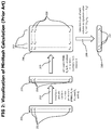
- visually describes the calculation of MinHash based signatures;
- Fig. 3
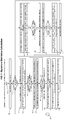
- visually describes the calculation of SuperMinHash based signatures;
- Fig. 4
- provides flow charts of processes to providing pseudo random number generator (PRNG) based on a hashing function;
- Fig. 5
- shows a block diagram of a signature generator for the run-time optimized calculation of SuperMinHash signatures;
- Fig. 6
- shows a flow chart of the processing of an incoming data element like a log line by the signal generator;
- Fig. 7
- provides a flow chart of the processing performed by the signature slot value generator to create signature values using a PRNG initialized with a single feature extracted from an incoming data element;
- Fig. 8
- shows a flow chart of an exemplary application of SuperMinHash signatures, which uses the signatures of two log lines to determine whether the two log lines are similar; and
- Fig. 9
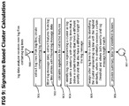
- provides the flow chart of a process that may be used to identify log data clusters and to provide summary data describing the identified clusters.
- Corresponding reference numerals indicate corresponding parts throughout the several views of the drawings.
- Example embodiments will now be described more fully with reference to the accompanying drawings.
- The described exemplary embodiments are directed to show the application of the SuperMinHash signatures for the analysis of log data. Although some qualities of SuperMinHash signatures match perfectly with the requirements of log analysis, like a higher precision for small signature sizes compared to conventional MinHash signatures (for details see Appendix A "SuperMinHash - A New Minwise Hashing Algorithm for Jaccard Similarity Estimation), SuperMinHash signatures may be applied in various other fields, like image processing, text processing or the determination of the similarity of graph structures.
- Referring now to
Fig. 1 which conceptually describes log analysis system directed to the identification of similar log lines and the determination of log line clusters (i.e. sets of similar log lines). - A
log file analyzer 100 receives and analyzes log files 105. The received log files may e.g. be produced by monitored processes during their execution. Those log files may describe execution conditions of those processes, including the occurrence of unexpected functional conditions, execution errors or unexpected high or low load conditions. Data contained in the log files may be used to analyze the behavior of the monitored processes. - The log file analyzer extracts and stored 120 log lines contained in incoming log files 105 in a
log data repository 103 in form oflog line entries 114. Typically, alog file 105 contains multiple log lines, each log line typically contains a time stamp indicating the point in time at which the logged event occurred, a severity indicator indicating the severity of the logged event and a log message that textually describes the occurred event. Thelog data repository 103 containslog line entries 114 for each log line received with alog file 105. Thesignature generator 101 is notified on new receiver log lines and fetches 121 those new log lines to createlog line signatures 107 for them. Thelog line signatures 107 are linked with their corresponding log line with alog line reference 113. The createdlog line signatures 107 are stored in a logline signature index 104. Typically,log line signatures 107 are sufficiently compact to enable the system to keep the whole logline signature index 104 in main memory. - The log line signature index may be used to process log line similarity requests, which e.g.
request log lines 114 in the log data repository that are similar to a given receivedlog line 127. Such requests may be received by a logline similarity analyzer 102 which first requests a signature for the givenlog line 122 from thesignature generator 101 and the uses the received signature to identify 124log line signatures 107 indicate similarlog line entries 114 in the logline signature index 104. The log line references 113 of identifiedlog line signatures 107 may be used to fetch the correspondinglog line entries 114 from thelog data repository 103 which may then be returned 128 by the log line similarity analyzer as response for the received request. The request may in addition to the given log file also similarity parameter that defines a required degree of similarity.Fig. 8 provides a flow chart that describes the similarity determination in more detail. - In addition to log line similarity determination, the
log file analyzer 100 may also identify log line clusters that summarize similar log lines. The log file analyzer may maintain a logline cluster index 108 which is updated 125 on new created log signatures. -
Log line signatures 107 typically represent a log line by a list of numbers calculated by a locality sensitive hash technique like SuperMinHash. The logline cluster index 108 may group of those numbers into segments and create signature segment storages 109 for each segment. As an example, calculated signatures may consist of 100 numbers and the log line cluster index may create 10 segments containing 10 of those numbers (e.g. segment 1 containsnumber 1 to 10,segment 2 contains numbers 11 to 20 and so on). Eachsignature segment storage 109 may contain multiplesegment value entries 110, which again contain avalue field 111 containing a value for the segment represented by the enclosingsignature segment storage 109 and amatching signatures list 112 containinglog signatures 107 having the same segment value. - On receipt of a new
log line signature 107, the log line cluster index may calculate the values for all segments of the signature and add it to the matching signatures of corresponding segment values. As example, the segment values for a new received signature may be 987, 876, 765 etc. The log line cluster index may add thesignature 107 to thematching signatures list 112 of thesegment value entry 110 representing the value 987 of thesignature segment storage 109 representing the first segment. The signature may also be added to matching signatures of thesegment value entry 110 representing value 876 of thesignature segment storage 109 representing the second segment etc. - A log
line cluster analyzer 106 may use the logline cluster index 108 to process log line cluster related requests, like e.g. the requests for size of the log line cluster to which a specific given log line belongs 129. Those requests may in addition contain parameters that are used to identify and define a log line cluster. As an example, the cluster identification parameter may define the number of required matching segments. - On receipt of a
cluster size request 129, the logline cluster analyzer 106 may first calculate the signature and then, based on the signature, calculate the segment values of the signature of the received given log line. The calculated segment values may further be used to selectsegment value records 110 with avalue 111 matching the corresponding segment value derived from the received log line. Thelog line signatures 107 contained in the matching signatures lists of the selected segment value records may be used as a set of candidate log line signatures describing the cluster to which the received log line belongs. A subsequent step may further refine and filter this set by a direct comparison of the candidate signatures with the signature of the received log line. As an example, additional segment values may be calculated for the candidate signatures and only signatures may be selected for which the number of segment values matching a segment value derived from the received log line exceeds a certain minimum as e.g. specified in the received cluster identification parameters. - Afterwards, the log
line cluster analyzer 106 may create a response for the received request that contains the size of the filtered candidate signature set as size of the cluster to which the received log line belongs. - A monitoring system may e.g. cyclically request the sizes of the identified log line clusters to create time series data that describes the frequency of log lines per identified log line cluster over time. This time series data may be processed to create baseline frequency data that corresponds to a normal operating condition of a monitored application. Time series data describing the current log line frequencies may then be compared to the baseline frequency data and a substantial deviation of the current log line frequency data from the baseline may be used as an indication for an abnormal operating condition of the monitored application.
- Coming now to
Fig. 2 , which graphically describes the calculation of a MinHash signature (prior art) out of an input data element, like a log line. In a first step, a set offeatures 200 containing features d1 -d n 201 is extracted from the input data element. In case of a log line, this may be the severity indicator of the log line and the individual words contained in the log message. Afterwards, a set ofPRNG 203 PRNG (R1 - Rn 204) is initialized for each feature d1 - dn using the value of the feature as initialization value for the PRNG. The initialization value or seed of a PRNG determines the sequence of pseudo random numbers created by the PRNG. Two PRNGs initialized with the same value create the same sequence of pseudo random numbers. Therefore, those PRNGs are also called deterministic random number generators. - After each PRNGs are used 205 to create a random number for each signature for each signature slot value, where all created random numbers are from an
interval I 207. - The created random numbers form a matrix of random numbers, where each
row 208 corresponds to a feature (d1 - dn) and each column corresponds to a signature slot value. The minimum value is selected from eachcolumn 209 and used asslot value 211 of the createdsignature 210. - Referring now to
Fig. 3 which visually describes the calculation of a SuperMinHash signature. The calculation also starts with the extraction of aset 200 offeatures 201 and theinitialization 202 of a set ofPRNGs 203, containing a PRNG for each feature (R1 - Rn). Afterwards, each PRNG is used 300 to create a m random numbers, where m is the number of required signature slots. The random numbers for each signature slot are created from an individual interval, where the intervals are pairwise non-overlapping, equidistant and equal-sized. As an example, the pseudo random numbers forsignature slot 1 may be selected from a continuous interval starting from 1 and including 1 ending with 2 and not including 2, the random numbers for signature slot may be selected from thecontinuous interval 2 including 2 to 3, excluding 3 etc. This creates amatrix 301 of n (number of features)rows 303 and m (number of slots) columns containing random numbers, where the random numbers of each column are selected from adifferent interval 302. - Afterwards, the PRNGs R1 - Rn are used 304 to create random permutation of each row of the
initial matrix 301. More specific, RPNG R1 may be used to create a random permutation ofrow 1, RPNG R2 may be used to create a random permutation ofrow 2 and so on. The result is a shuffledmatrix 305 containing shuffledrows 306 of random numbers, eachrow 306 of the shuffledmatrix 305 representing a feature (i.e. d1 - dn) and containing random numbers from individual, pairwise non-overlapping, equidistant and equal-sized intervals, where the random numbers. Both the random numbers and the random permutation of a row are created using a RPNG that was initialized with the feature corresponding to the row. The Fisher-Yates algorithm (for details see https://en.wikipedia.org/wiki/Fisher-Yates_shuffle) may be used for the efficient creation of random permutations. - Each column of the shuffled matrix corresponds to a feature slot. The minimum value of each column is selected 307 and this minimum value is used as value for the
signature slot 309 of the calculatedsignature 308. - Coming now to
Fig. 4 which conceptually describes processes that may be used to efficiently create pseudo random numbers as required for the calculation of SuperMinHash signatures. -
Fig. 4a describes the initialization of a PRNG for a given feature value di. The process starts withstep 400 when a new feature value is received and continues withstep 401 which first initializes a hash counter withvalue 0 then stores the hash counter and the feature value in an object representing the PRNG. Afterwards, the hash function that should be used by the PRNG is initialized instep 402. Step 402 may e.g. select the type of hash function that should be used by the PRNG. Hash functions that may be used by the PRNG include but are not limited to murmur3 or xxHash. Followingstep 403 initializes a random bit FIFO (First In - First Out) buffer or queue that may later be used to temporarily store created random bits. Afterward, the process ends withstep 404. -
Fig. 4b describes the processing of a request for n random bits by a PRNG. The process starts withstep 410 when the PRNG receives such a request.Subsequent decision step 411 determines whether the random bit FIFO buffer contains sufficient random bits to fulfill the request. In case the number of available random bits is not sufficient,step 412 is executed which combines the feature value (as stored in step 401) with the hash counter (also initialized and stored in step 401) to create an input value for the hash function.Subsequent step 413 applies the value created bystep 412 as input value for the hash function of the PRNG. The result of the evaluation of the hash function are m random bits which are stored in the random bit FIFO buffer. In addition,step 413 increments the hash counter. - Afterwards,
step 411 is executed again and checks if the random bit FIFO buffer now contains sufficient random bits to fulfill the request. In case the number of available random bits is still not sufficient,step 413 is executed. - Otherwise,
step 414 is executed which selects the requested n random bits from the random bit FIFO buffer.Subsequent step 415 removes the selected bits from the random bit FIFO buffer and step 416 returns the selected random bits to the sender of the request. Typically, reading data from FIFO buffer or queue also removes the read data, which combinessteps - The process then ends with
step 416. - Coming now to
Fig. 5 which provides a block diagram of a SuperMinHash basedsignal generator 101 that performs a runtime-optimized calculation of SuperMinHash signatures. A first optimization combines the calculation of hash values for a specific interval (seematrix 302 inFig. 3 ) and the calculation of the random permutation (seematrix 305 inFig.3 ) for the processing of a feature into one step that piece by piece calculates portions of the random permutation as they are needed. - A second optimization maintains the facts that the random numbers are created for different, increasing intervals and that random numbers that are greater than the currently greates random number in the shuffled
matrix 305 cannot influence the resulting signature slots. The second optimization may e.g. maintain a histogram of calculated slot value candidates and use this histogram to determine the greatest overall slot value candidate during the calculation process. - The slot value candidates created for individual features follow a strictly increasing pattern, as slot values are selected from non-overlapping intervals with an increasing lower bound. In case the lower boundary of the interval from which the next slot value candidate for the current feature should be selected is greater than the greatest overall slot value candidate, calculation of the next slot value and all further slot values for that feature can be skipped, as they cannot influence any resulting signature slot value.
- The
signature generator 101 contains afeature extractor 500, which receives 121, 122 incominglog lines entries 114 and extracts a feature set 502 (e.g. severity indicator and words of the log message) from the received log line entries. The feature set 501 may contain n different features. The feature set is forwarded 503 to a feature setprocessor 504 which iterates over the features in the received feature set and processes them to create a correspondinglog line signature 107. - The
signal generator 101 also contains aslot value histogram 520 with mbins 521, each bin representing an interval from which a random value is selected as signature slot value candidate, seeintervals 302 onFig. 3 . As an example, those intervals may be specified as [i, i+1), where i may be the signature slot index ranging from 1 to m, where m is the number of signature slots and where "[" indicates an inclusive lower interval boundary (including the number specifying the lower interval boundary) and ")" indicates an exclusive upper interval boundary (excluding the number specifying the upper interval boundary). Next to theslot value histogram 520, thesignal generator 101 also contains a shuffledslot index array 509 and a slot shuffle state array which are used to maintain data required for the peace-wise and interleaved calculation of the random permutation of signature slot indexes, and a signatureslot value calculator 517, which receives individual features from the feature setprocessor 504 and interacts withslot value histogram 520, shuffledslot index array 509 and slotshuffle state array 511 to createupdates 524 for values ofsignature slots 523 of asignature 522 contained in a logline signature record 107 corresponding to a received 121, 122log line record 114. On receiving a new feature set, the feature processor initializes theslot value histogram 520 by setting the values ofbin 1 to m-1 to 0 and setting the value of bin m to m. This indicates that at the beginning of the processing of a new feature set, all slot values are in the interval that covers the highest value range, i.e. the interval [m, m+1). - In addition, the slot
shuffle state entries 510 of the slot shuffle state array (q) 509 may be set to an invalid feature index value. This invalid feature index value may e.g. be 0 or -1. - Further, a new shuffled slot index array 511 (p) of size m, containing shuffled slot index entries may be allocated, and the slot values 523 of the
signature 522 may be set to the highest possible value to indicate not yet initialized slots. - After initialization of
slot value histogram 520, shuffledslot index array 509 and slotshuffle state array 511, the feature setprocessor 504 may sequentially trigger the execution of the processes performed by the signatureslot value calculator 517 for each individual feature. The signal slot value calculator uses the shuffledslot index array 509 and the slotshuffle state array 511 to perform the calculation of a random permutation of slot indexes and the calculation of slot update values in an interleaved way. - The signature
slot value calculator 517 may update 513 the shuffled slot index array to perform an alternating piecewise calculation of a random slot index permutation and it may further fetch the 514 index of a slot that is an updated candidate from the shuffled slot index array. In addition, the signatureslot value calculator 517 may update 515 and fetch 516 feature shuffle data from the slot shuffle state array to coordinate the piecewise permutation calculation with the iterative processing of individual features. - The signature slot value calculator may further, in case it calculated a value for a
signature slot 523 that is lower than the current value of thesignature slot 523, update 524 the value of the signature slot to the calculated value. A detailed description of the processing performed by the signatureslot value calculator 517 can be found inFig. 7 . Referring now toFig. 6 , which provides a flow chart of the processing performed by thesignature generator 101 on the receipt of a new log line. The process starts withstep 600 when the signal generator receives a newlog line entry 114.Subsequent step 601 extracts the feature set from the log line entry (e.g. words of the log message and log severity indicator). Followingstep 602 creates logline signature record 107, sets the values of theslots 523 of thesignature 522 to the maximum value to indicate not initialized slots, and sets thelog line reference 113 to refer to the receivedlog line entry 114. Afterwards step 603 initializes theslot value histogram 520 by setting the counts ofbin 1 to bin m-1 to 0 and the value of bin m to m, to represent the current state of the signature slots 523 (all slot value at highest value). Step 603 may further set a global highest slot index value to m, indicating that the highest slot value is in the highest slot value interval 302 [m, m+1) or higher. The global highest slot index value may further be maintained by the signalslot value calculator 517 during the calculation and update of signature slot values and may be used to determine when further slot value calculations for a feature can be skipped because they can only produce values that are higher than the global highest slot index value. Only values that are lower than than the global highest slot index value can potentially change the value of asignature slot 523. - Following
step 604 allocates a new shuffledslot index array 509. The shuffled slot index array may be an array of size m (number of signature slots), containing integer elements that can at least hold the maximum index number m. - Step 605 afterwards initializes the slot
shuffle state array 511 by setting the m feature index entries 512 (integer elements capable to hold the maximum index number m) to an invalid feature index like 0 or -1. - Following
decision step 606 determines if a next feature is available for processing. In case no next feature is available, the process ends withstep 610. Otherwise step 607 is executed which fetches the next feature, which is followed bystep 608 which initializes a PRNG for the fetched feature as described inFig. 4a . Afterwards,step 608 is executed, which forwards the initialized PRNG and the feature index to the signature slot value calculator. A detailed description of the processing performed by the signatureslot value calculator 517 can be found inFig. 7 . - Coming now to
Fig. 7 which contains a flow chart that conceptually describes the processing performed by the signatureslot value calculator 517 on the receipt of an initialized PRNG and a feature index. - The process starts with
step 700 when the signatureslot value calculator 517 receives an initialized PRNG and a current feature index. Followingstep 701 sets the current slot index to 1 to start processing the first slot. Followingdecision step 702 checks whether the current slot index is greater than the global highest slot index, and in case the current slot index is greater, terminates the process withstep 720. In case the current slot index is not greater than the global highest slot index, the process continues withstep 703 which fetches a floating-point pseudo random number in the interval [0, 1) from the PRNG as slot value contribution and continues withstep 704 which fetches an integer random number from the PRNG out of the value range from current slot index (inclusive) to number of slots m (also inclusive) as slot index permutation contribution. Both random numbers may be created using random bit sequences provided by the PRNG as described inFig. 4b . - Following
decision step 705 checks whether the value of the slot shuffle state array at the position of the current slot index is unequal to the current feature index. In case the values are equal, the process continues withstep 708. - Otherwise,
step 706 is executed which sets the value of thefeature index 512 of the slotshuffle state array 511 at the position of the current slot index to the current feature index, followed bystep 707 which sets the shuffledslot index 510 of the shuffledslot index array 509 at the position of the current slot index to the current slot index. Afterwards,decision step 708 is executed which checks whether the value of the slot shuffle state array at position of the index permutation contribution is unequal to the current feature index. In case the values are equal, the process continues withstep 711. Otherwise, 709 is executed which sets the value of thefeature index 512 of the slotshuffle state array 511 at the position of the slot index permutation contribution to the current feature index, followed by step 710 which sets the shuffledslot index 510 of the shuffledslot index array 509 at the position of the slot index permutation contribution to the current slot index. - Following
step 711 swaps the shuffledslot index entries 510 of the shuffledslot index array 509 at positions current slot index and slot index permutation contribution to perform the calculation of the next required portion of the random index permutation. - Afterwards,
step 712 is executed which fetches the slot update index for theupdate candidate slot 523 of the currently calculatedsignature 522. Step 712 fetches the shuffledslot index 519 at the position of the current slot index from the shuffledslot index array 510. - Following step 713 uses the slot update index determined in
step 712 to fetch the current value of thesignature slot 523 at the position of the slot update index. Afterwards step 713 calculates an update value for the selected slot as the sum of the current index and the slot value contribution (this sum is a random number in the interval [current index, current index +1)). - Afterwards,
decision step 714 is executed which checks whether the slot update value calculated by step 713 is smaller than the current value of the selected slot. In case the value is not smaller, the process continues withstep 719. - Otherwise, the process continues with
step 715, which reconstructs the slot index that was used to create the current value of the of the signature slot that was selected bystep 712 for the update. The reconstruction of the slot index permutation contribution may be performed by applying a floor function to the current value of the slot get the next lower integer value. In case the slot was not updated before, its current value is still at the initial maximum value that can be held by the data type of thesignature slots 523. In this case, the maximum slot index m is used as reconstructed slot index permutation contribution. - Following
step 716 sets the value of the signature slot at the position selected bystep 712 to the slot update value calculated in step 713. - Afterwards, decision step 717 check whether the current slot index is smaller than the previous slot index calculated in
step 715. In case the current slot index is not smaller, the process continues withstep 719. - Otherwise,
step 718 is executed which updates theslot value histogram 520 by decrementing the count of thehistogram bin 521 at the position of the previous slot index calculated instep 715 and incrementing the count of thehistogram bin 521 at the position of the current slot index. This updates theslot value histogram 520 according to the change of the signature slot values performed bystep 716. - Afterwards,
step 718 determines the global highest slot index by selecting the highest index of ahistogram bin 521 of the slot value histogram that has a count greater than 0 and using this highest index as global highest slot index. - Following
step 719 increments the current slot index and the process continues withstep 702. - Coming now to
Fig. 8 which provides a flow chart of a process that perform a signature-based similarity calculation, to demonstrate an exemplary application of SuperMinHash signatures. - The process starts with
step 800, when the logline similarity analyzer 102 receives twolog line entries 114 for which a determination whether they are similar is requested. Followingstep 801 fetches the signatures of the received log line entries, e.g. by forwarding thelog line entries 114 to thesignature generator 101 for the calculation of the corresponding signatures. Afterwards,step 802 is executed which calculates a similarity estimate value for the log line entries based on their signatures. The similarity estimate value may be calculated by determining the number of pairwise equal signature slot values (i.e. the value of a slot at a certain position is equal for both signatures) and dividing the number of slots (i.e. m) by the number of slots having a pairwise equal value. The result of this division is an estimate for the Jaccard coefficient (see e.g. https://en.wikipedia.org/wiki/Jaccard_index) which is a measure for the similarity of sets. - Following
decision step 803 compares the similarity estimate value with a specific threshold. In case the similarity estimate value exceeds the threshold,step 804 is executed which indicates that the two log line entries are similar. - Otherwise,
step 805 is executed which indicates that the two log lines are not similar. - After
step step 806. Further details regarding the methods set forth herein are found in the attached Appendix. - Coming now to
Fig. 9 , which describes a process that may be used by some variant embodiments to identify clusters of log lines. The process starts withstep 900 when the log data analyzer receives new log data in form of log files containing long lines. Followingstep 901 extracts the log lines from the received log files and creates correspondinglog entries 114, which may be stored in the log data repository. - Following
step 902 filters the log message data of the log entries by e.g. remove numeric data or special characters from the log line. The intention of removing such data from the log lines is to remove variable parts of otherwise similar log message. As an example, a log message may report that a specific operation lasted longer than expected and contain a numeric value describing the time the operation lasted. Removing this numeric value increases the similarity of those log entries that also describe very similar events. Step 902 also extracts features from the log entry after the filtering step. The extracted features may contain but are not limited to a severity indicator and the words contained in the log message. - Afterwards,
step 903 is executed which calculates the signatures of the received log entries as described before. -
Subsequent step 904 calculates the similarity index (e.g. as described inFig. 8 ) for all pairs of received log entries and selects those log entries that have a similarity index with all other log entries that is below a certain threshold and that have a different severity indicator and a different length of their corresponding log message as log entries representing a cluster of log entries. - Following
step 905 iterates over the remaining log entries that were not identified as cluster representing log line instep 904 and identifies for each remaining log entry the cluster representing log line with the highest similarity index. Step 905 further checks whether the similarity index exceeds a certain threshold and whether severity indicator of both log lines and length of the log message match. In case all matches, the log line is assigned to the cluster. - Following
step 906 creates summary data for the identified log data clusters, e.g. in form of the log line representing the cluster and the number of log lines assigned to the cluster. - The process then ends with
step 907. - The techniques described herein may be implemented by one or more computer programs executed by one or more processors. The computer programs include processor-executable instructions that are stored on a non-transitory tangible computer readable medium. The computer programs may also include stored data. Non-limiting examples of the non-transitory tangible computer readable medium are nonvolatile memory, magnetic storage, and optical storage.
- Some portions of the above description present the techniques described herein in terms of algorithms and symbolic representations of operations on information. These algorithmic descriptions and representations are the means used by those skilled in the data processing arts to most effectively convey the substance of their work to others skilled in the art. These operations, while described functionally or logically, are understood to be implemented by computer programs. Furthermore, it has also proven convenient at times to refer to these arrangements of operations as modules or by functional names, without loss of generality.
- Unless specifically stated otherwise as apparent from the above discussion, it is appreciated that throughout the description, discussions utilizing terms such as "processing" or "computing" or "calculating" or "determining" or "displaying" or the like, refer to the action and processes of a computer system, or similar electronic computing device, that manipulates and transforms data represented as physical (electronic) quantities within the computer system memories or registers or other such information storage, transmission or display devices.
- Certain aspects of the described techniques include process steps and instructions described herein in the form of an algorithm. It should be noted that the described process steps and instructions could be embodied in software, firmware or hardware, and when embodied in software, could be downloaded to reside on and be operated from different platforms used by real time network operating systems.
- The present disclosure also relates to an apparatus for performing the operations herein. This apparatus may be specially constructed for the required purposes, or it may comprise a computer selectively activated or reconfigured by a computer program stored on a computer readable medium that can be accessed by the computer. Such a computer program may be stored in a tangible computer readable storage medium, such as, but is not limited to, any type of disk including floppy disks, optical disks, CD-ROMs, magnetic-optical disks, read-only memories (ROMs), random access memories (RAMs), EPROMs, EEPROMs, magnetic or optical cards, application specific integrated circuits (ASICs), or any type of media suitable for storing electronic instructions, and each coupled to a computer system bus. Furthermore, the computers referred to in the specification may include a single processor or may be architectures employing multiple processor designs for increased computing capability.
- The algorithms and operations presented herein are not inherently related to any particular computer or other apparatus. Various systems may also be used with programs in accordance with the teachings herein, or it may prove convenient to construct more specialized apparatuses to perform the required method steps. The required structure for a variety of these systems will be apparent to those of skill in the art, along with equivalent variations. In addition, the present disclosure is not described with reference to any particular programming language. It is appreciated that a variety of programming languages may be used to implement the teachings of the present disclosure as described herein.
- The foregoing description of the embodiments has been provided for purposes of illustration and description. It is not intended to be exhaustive or to limit the disclosure. Individual elements or features of a particular embodiment are generally not limited to that particular embodiment, but, where applicable, are interchangeable and can be used in a selected embodiment, even if not specifically shown or described. The same may also be varied in many ways. Such variations are not to be regarded as a departure from the disclosure, and all such modifications are intended to be included within the scope of the disclosure.
Claims (11)
- A method for identifying problem resolutions in a computing environment, comprising:- receiving a problem graph for a current problem in the computing environment, wherein the problem graph describes abnormal operating conditions in the computing environment;- generating a signature of interest from the problem graph;- comparing the signature of interest to a plurality of signatures stored in an index, where each signature in the plurality of signatures is derived from a previous problem graph and has an associated problem resolution, such that the previous problem graph represents an occurrence of a previous problem in the computing environment; and- identifying one or more previous problems that are similar to the current problem based on the comparison of the signature of interest to the plurality of signatures, wherein the signature of interest is generated by- extracting a group of data features from the problem graph, where the group of data features preserves the connection structure of the graph;- for each extracted data feature in the group of data features, generating a list of random numbers using a pseudo random number generator, where the random numbers in each of the lists of random numbers are generated from different non-overlapping intervals;- for each list of random numbers, creating a random permutation of the list of random numbers;- grouping the random numbers from the lists of random numbers into subsets of random numbers, where the random numbers having same placement in the lists of random numbers are grouped into the same subset of random numbers;- from each subset of random numbers, selecting a particular random number from a subset of random numbers, where the particular random number has the smallest value amongst the random numbers in the subset of random numbers; and- concatenating the selected random numbers to form the signature of interest from the problem graph.
- The method of claim 1, wherein nodes comprising the problem graph represent events in the computing environment and edges in the problem graph represent a causal relationship between events in the problem graph.
- The method of claim 2, wherein extracting a group of data features from the problem graph further comprises creating a tuple for each edge in the problem graph, such that a given tuple includes data identifying nodes connected by a given edge.
- The method of claim 3, wherein extracting a group of data features from the problem graph further comprises identifying a causality probability associated with each edge in the problem graph, mapping the causality probability to one of a set of discrete values for the causality probability and adding the mapped discrete vale to the tuple for the given edge.
- The method of at least one of the preceding claims, wherein identifying one or more previous problems that are similar to the current problem further comprises comparing each number in the signature of interest to corresponding number in a given signature from the plurality of signatures and totaling how many numbers are identical between the signature of interest and the given signature.
- The method of at least one of the preceding claims, wherein generating a list of random numbers includes applying a hash function to at least a portion of the extracted data feature.
- The method of at least one of the preceding claims, further comprising initializing a pseudo random number generator for each of the extracted data features in the group of data features.
- The method of claim 7, further comprising initializing the pseudo random number generator using a value of the extracted data feature.
- The method of at least one of the preceding claims, further comprising creating a random permutation of the row using Fisher-Yates shuffle method.
- The method of at least one of the preceding claims, further comprising combining the step of generating a list of random numbers and creating a random permutation into one iterative step.
- The method of at least one of the preceding claims, further comprising- for each extracted data feature in the group of data features, arranging non-overlapping intervals with values defining the non-overlapping intervals in ascending order;- tracking value of a random number having highest value amongst the generated random numbers generated for the lists of random numbers; and- for a given extracted feature, ceasing to generate a list of random numbers when a lower bound of the corresponding non-overlapping interval for the given extracted feature exceeds the tracked value.
Priority Applications (1)
| Application Number | Priority Date | Filing Date | Title |
|---|---|---|---|
| EP20168307.5A EP3751430A1 (en) | 2019-06-13 | 2020-04-06 | Method and system for log data analytics based on superminhash signatures |
Applications Claiming Priority (2)
| Application Number | Priority Date | Filing Date | Title |
|---|---|---|---|
| US201862685380P | 2018-06-15 | 2018-06-15 | |
| US16/440,439 US11431475B2 (en) | 2018-06-15 | 2019-06-13 | Method and system for log data analytics based on SuperMinHash signatures |
Publications (1)
| Publication Number | Publication Date |
|---|---|
| EP3582115A1 true EP3582115A1 (en) | 2019-12-18 |
Family
ID=67137514
Family Applications (1)
| Application Number | Title | Priority Date | Filing Date |
|---|---|---|---|
| EP19180273.5A Withdrawn EP3582115A1 (en) | 2018-06-15 | 2019-06-14 | Method and system for log data analytics based on superminhash signatures |
Country Status (2)
| Country | Link |
|---|---|
| US (3) | US11431475B2 (en) |
| EP (1) | EP3582115A1 (en) |
Cited By (1)
| Publication number | Priority date | Publication date | Assignee | Title |
|---|---|---|---|---|
| WO2021109724A1 (en) * | 2019-12-02 | 2021-06-10 | 华为技术有限公司 | Log anomaly detection method and apparatus |
Families Citing this family (12)
| Publication number | Priority date | Publication date | Assignee | Title |
|---|---|---|---|---|
| US11693918B2 (en) * | 2020-06-05 | 2023-07-04 | Vmware, Inc. | Methods and systems for reducing volumes of log messages sent to a data center |
| CN113918941B (en) * | 2020-07-07 | 2026-06-26 | 华为云计算技术有限公司 | Methods, apparatus, computing devices, and storage media for detecting abnormal behavior |
| CN112269879B (en) * | 2020-11-02 | 2023-03-31 | 武汉烽火众智数字技术有限责任公司 | Method and equipment for analyzing middle station log based on k-means algorithm |
| US20220253426A1 (en) * | 2021-02-08 | 2022-08-11 | International Business Machines Corporation | Explaining outliers in time series and evaluating anomaly detection methods |
| US20220277196A1 (en) * | 2021-03-01 | 2022-09-01 | Alexander Calhoun Flint | Method and system for securely storing data for use with artificial neural networks |
| DE102021210846A1 (en) * | 2021-09-28 | 2023-03-30 | Robert Bosch Gesellschaft mit beschränkter Haftung | Method for generating a graph structure for training a graph neural network |
| CN114401080B (en) * | 2021-12-20 | 2025-03-18 | 武汉天喻信息产业股份有限公司 | A method and system for finding intersection of private sets |
| US20240004933A1 (en) * | 2022-06-29 | 2024-01-04 | Tigergraph, Inc. | Minhash signatures as vertices for fuzzy string match on graph |
| US12177361B2 (en) * | 2022-10-11 | 2024-12-24 | Salesforce, Inc. | Avoiding information disclosure about user actions on configuration data submissions in multi-tenant network management interfaces |
| CN118364098A (en) * | 2023-01-18 | 2024-07-19 | 中国科学院计算机网络信息中心 | An automatic classification method for crash events |
| DE102023117506A1 (en) * | 2023-07-03 | 2025-01-09 | TRUMPF Werkzeugmaschinen SE + Co. KG | Computer-implemented method for reducing error-indicating log files from a system |
| EP4767556A1 (en) * | 2023-09-11 | 2026-07-01 | Jio Platforms Limited | SYSTEM AND METHOD FOR TRACKING A USER'S CALL FLOW DATA IN A NETWORK |
Family Cites Families (7)
| Publication number | Priority date | Publication date | Assignee | Title |
|---|---|---|---|---|
| US7024592B1 (en) * | 2000-08-07 | 2006-04-04 | Cigital | Method for reducing catastrophic failures in continuously operating software systems |
| US7574409B2 (en) | 2004-11-04 | 2009-08-11 | Vericept Corporation | Method, apparatus, and system for clustering and classification |
| GB2540562B (en) | 2015-07-21 | 2019-09-04 | Advanced Risc Mach Ltd | Method of and apparatus for generating a signature representative of the content of an array of data |
| US10460340B2 (en) * | 2015-07-31 | 2019-10-29 | Wideorbit Inc. | Verifying ad requests |
| US10382410B2 (en) * | 2016-01-12 | 2019-08-13 | Advanced Micro Devices, Inc. | Memory operation encryption |
| US10296748B2 (en) * | 2016-02-25 | 2019-05-21 | Sas Institute Inc. | Simulated attack generator for testing a cybersecurity system |
| US20180203916A1 (en) * | 2017-01-19 | 2018-07-19 | Acquire Media Ventures Inc. | Data clustering with reduced partial signature matching using key-value storage and retrieval |
-
2019
- 2019-06-13 US US16/440,439 patent/US11431475B2/en active Active
- 2019-06-14 EP EP19180273.5A patent/EP3582115A1/en not_active Withdrawn
-
2022
- 2022-08-12 US US17/887,079 patent/US11804952B2/en active Active
-
2023
- 2023-10-05 US US18/376,882 patent/US12160503B2/en active Active
Non-Patent Citations (4)
| Title |
|---|
| ANIMESH NANDI ET AL: "Anomaly Detection Using Program Control Flow Graph Mining From Execution Logs", PROCEEDINGS OF THE 22ND ACM SIGKDD INTERNATIONAL CONFERENCE ON KNOWLEDGE DISCOVERY AND DATA MINING, KDD '16, ACM PRESS, NEW YORK, NEW YORK, USA, 13 August 2016 (2016-08-13), pages 215 - 224, XP058276841, ISBN: 978-1-4503-4232-2, DOI: 10.1145/2939672.2939712 * |
| OTMAR ERTL: "SuperMinHash - A New Minwise Hashing Algorithm for Jaccard Similarity Estimation", ARXIV.ORG, CORNELL UNIVERSITY LIBRARY, 201 OLIN LIBRARY CORNELL UNIVERSITY ITHACA, NY 14853, 18 June 2017 (2017-06-18), XP080770671 * |
| STOKES JACK W ET AL: "MART: Targeted attack detection on a compromised network", MILCOM 2016 - 2016 IEEE MILITARY COMMUNICATIONS CONFERENCE, IEEE, 1 November 2016 (2016-11-01), pages 988 - 997, XP033028265, DOI: 10.1109/MILCOM.2016.7795459 * |
| TRISTAN CACQUERAY: "Anomaly Detection in CI logs", 14 November 2017 (2017-11-14), XP055625772, Retrieved from the Internet <URL:https://blogs.rdoproject.org/2017/11/anomaly-detection-in-ci-logs/> [retrieved on 20190924] * |
Cited By (1)
| Publication number | Priority date | Publication date | Assignee | Title |
|---|---|---|---|---|
| WO2021109724A1 (en) * | 2019-12-02 | 2021-06-10 | 华为技术有限公司 | Log anomaly detection method and apparatus |
Also Published As
| Publication number | Publication date |
|---|---|
| US20220393854A1 (en) | 2022-12-08 |
| US11804952B2 (en) | 2023-10-31 |
| US12160503B2 (en) | 2024-12-03 |
| US20240039699A1 (en) | 2024-02-01 |
| US11431475B2 (en) | 2022-08-30 |
| US20190386819A1 (en) | 2019-12-19 |
Similar Documents
| Publication | Publication Date | Title |
|---|---|---|
| US11804952B2 (en) | Method and system for log data analytics based on SuperMinHash signatures | |
| US11681574B2 (en) | Method and system for real-time and scalable anomaly detection and classification of multi-dimensional multivariate high-frequency transaction data in a distributed environment | |
| US20160055044A1 (en) | Fault analysis method, fault analysis system, and storage medium | |
| US9424288B2 (en) | Analyzing database cluster behavior by transforming discrete time series measurements | |
| US9921937B2 (en) | Behavior clustering analysis and alerting system for computer applications | |
| US10452458B2 (en) | Computer performance prediction using search technologies | |
| US10282276B2 (en) | Fingerprint-initiated trace extraction | |
| US9870294B2 (en) | Visualization of behavior clustering of computer applications | |
| CN111160021A (en) | Log template extraction method and device | |
| US11392446B2 (en) | Cross-correlation of metrics for anomaly root cause identification | |
| US20160321331A1 (en) | Device and method | |
| CN115033453B (en) | Abnormality detection method, device, equipment, storage medium and program | |
| EP4722924A2 (en) | Computer performance prediction using search technologies | |
| WO2021188196A1 (en) | Causality determination of upgrade regressions via comparisons of telemetry data | |
| Park et al. | Cell trees: An adaptive synopsis structure for clustering multi-dimensional on-line data streams | |
| US12061878B2 (en) | Method and system for calculating minwise hash signatures from weighted sets | |
| US11914704B2 (en) | Method and system for detecting coordinated attacks against computing resources using statistical analyses | |
| Falessi et al. | Preserving order of data when validating defect prediction models | |
| Sauvanaud et al. | Data stream clustering for online anomaly detection in cloud applications | |
| US12585532B2 (en) | Framework for selecting thresholds for anomaly detection models and generating quantitative explanations | |
| CN112434294A (en) | Malicious code detection method, terminal device and storage medium | |
| US11630818B2 (en) | Iterative performance analysis with interval expansion | |
| EP3751430A1 (en) | Method and system for log data analytics based on superminhash signatures | |
| US20250231768A1 (en) | Analysis function imparting method, analysis function imparting device, and analysis function imparting program | |
| CN111666173B (en) | Error message processing method, device, monitoring system and medium |
Legal Events
| Date | Code | Title | Description |
|---|---|---|---|
| PUAI | Public reference made under article 153(3) epc to a published international application that has entered the european phase |
Free format text: ORIGINAL CODE: 0009012 |
|
| AK | Designated contracting states |
Kind code of ref document: A1 Designated state(s): AL AT BE BG CH CY CZ DE DK EE ES FI FR GB GR HR HU IE IS IT LI LT LU LV MC MK MT NL NO PL PT RO RS SE SI SK SM TR |
|
| AX | Request for extension of the european patent |
Extension state: BA ME |
|
| STAA | Information on the status of an ep patent application or granted ep patent |
Free format text: STATUS: THE APPLICATION HAS BEEN WITHDRAWN |
|
| 18W | Application withdrawn |
Effective date: 20200513 |