EP3581948B1 - Apparatus for verifying electrical connectivity - Google Patents
Apparatus for verifying electrical connectivity Download PDFInfo
- Publication number
- EP3581948B1 EP3581948B1 EP19176417.4A EP19176417A EP3581948B1 EP 3581948 B1 EP3581948 B1 EP 3581948B1 EP 19176417 A EP19176417 A EP 19176417A EP 3581948 B1 EP3581948 B1 EP 3581948B1
- Authority
- EP
- European Patent Office
- Prior art keywords
- signal
- processor
- electrical connectivity
- connection unit
- devices
- Prior art date
- Legal status (The legal status is an assumption and is not a legal conclusion. Google has not performed a legal analysis and makes no representation as to the accuracy of the status listed.)
- Active
Links
Images


Classifications
-
- B—PERFORMING OPERATIONS; TRANSPORTING
- B60—VEHICLES IN GENERAL
- B60L—PROPULSION OF ELECTRICALLY-PROPELLED VEHICLES; SUPPLYING ELECTRIC POWER FOR AUXILIARY EQUIPMENT OF ELECTRICALLY-PROPELLED VEHICLES; ELECTRODYNAMIC BRAKE SYSTEMS FOR VEHICLES IN GENERAL; MAGNETIC SUSPENSION OR LEVITATION FOR VEHICLES; MONITORING OPERATING VARIABLES OF ELECTRICALLY-PROPELLED VEHICLES; ELECTRIC SAFETY DEVICES FOR ELECTRICALLY-PROPELLED VEHICLES
- B60L3/00—Electric devices on electrically-propelled vehicles for safety purposes; Monitoring operating variables, e.g. speed, deceleration or energy consumption
- B60L3/0023—Detecting, eliminating, remedying or compensating for drive train abnormalities, e.g. failures within the drive train
- B60L3/0046—Detecting, eliminating, remedying or compensating for drive train abnormalities, e.g. failures within the drive train relating to electric energy storage systems, e.g. batteries or capacitors
-
- G—PHYSICS
- G01—MEASURING; TESTING
- G01R—MEASURING ELECTRIC VARIABLES; MEASURING MAGNETIC VARIABLES
- G01R31/00—Arrangements for testing electric properties; Arrangements for locating electric faults; Arrangements for electrical testing characterised by what is being tested not provided for elsewhere
- G01R31/36—Arrangements for testing, measuring or monitoring the electrical condition of accumulators or electric batteries, e.g. capacity or state of charge [SoC]
-
- G—PHYSICS
- G01—MEASURING; TESTING
- G01R—MEASURING ELECTRIC VARIABLES; MEASURING MAGNETIC VARIABLES
- G01R31/00—Arrangements for testing electric properties; Arrangements for locating electric faults; Arrangements for electrical testing characterised by what is being tested not provided for elsewhere
- G01R31/50—Testing of electric apparatus, lines, cables or components for short-circuits, continuity, leakage current or incorrect line connections
- G01R31/66—Testing of connections, e.g. of plugs or non-disconnectable joints
- G01R31/67—Testing the correctness of wire connections in electric apparatus or circuits
-
- H—ELECTRICITY
- H01—ELECTRIC ELEMENTS
- H01M—PROCESSES OR MEANS, e.g. BATTERIES, FOR THE DIRECT CONVERSION OF CHEMICAL ENERGY INTO ELECTRICAL ENERGY
- H01M50/00—Constructional details or processes of manufacture of the non-active parts of electrochemical cells other than fuel cells, e.g. hybrid cells
- H01M50/20—Mountings; Secondary casings or frames; Racks, modules or packs; Suspension devices; Shock absorbers; Transport or carrying devices; Holders
-
- H—ELECTRICITY
- H02—GENERATION; CONVERSION OR DISTRIBUTION OF ELECTRIC POWER
- H02J—ELECTRIC POWER NETWORKS; CIRCUIT ARRANGEMENTS OR SYSTEMS FOR SUPPLYING OR DISTRIBUTING ELECTRIC POWER; SYSTEMS FOR STORING ELECTRIC ENERGY
- H02J7/00—Circuit arrangements for charging or discharging batteries or for supplying loads from batteries
- H02J7/70—Circuit arrangements for charging or discharging batteries or for supplying loads from batteries characterised by the mechanical construction
- H02J7/751—Circuit arrangements for charging or discharging batteries or for supplying loads from batteries characterised by the mechanical construction concerning the insertion or the connection of the batteries
-
- B—PERFORMING OPERATIONS; TRANSPORTING
- B60—VEHICLES IN GENERAL
- B60Y—INDEXING SCHEME RELATING TO ASPECTS CROSS-CUTTING VEHICLE TECHNOLOGY
- B60Y2200/00—Type of vehicle
- B60Y2200/90—Vehicles comprising electric prime movers
- B60Y2200/91—Electric vehicles
-
- Y—GENERAL TAGGING OF NEW TECHNOLOGICAL DEVELOPMENTS; GENERAL TAGGING OF CROSS-SECTIONAL TECHNOLOGIES SPANNING OVER SEVERAL SECTIONS OF THE IPC; TECHNICAL SUBJECTS COVERED BY FORMER USPC CROSS-REFERENCE ART COLLECTIONS [XRACs] AND DIGESTS
- Y02—TECHNOLOGIES OR APPLICATIONS FOR MITIGATION OR ADAPTATION AGAINST CLIMATE CHANGE
- Y02E—REDUCTION OF GREENHOUSE GAS [GHG] EMISSIONS, RELATED TO ENERGY GENERATION, TRANSMISSION OR DISTRIBUTION
- Y02E60/00—Enabling technologies; Technologies with a potential or indirect contribution to GHG emissions mitigation
- Y02E60/10—Energy storage using batteries
Definitions
- One or more embodiments relate to an apparatus for verifying electrical connectivity.
- Prior art US2010/182155 , US2007/216356 , and US2009/237035 teach circuits for determining whether a battery is connected to a charger.
- Prior art US2015/309118 teaches a circuit for determining the state of a safety plug in a battery.
- Prior art US2016/069945 discloses a circuit for determining a faulty connection in a car battery.
- Prior art US2016/238665 discloses a circuit for measuring the resistance of a battery connector.
- One or more embodiments include an apparatus for securely verifying the electrical connectivity between two electronic devices to be coupled to each other.
- One or more embodiments include an apparatus for securely verifying the electrical connectivity between two devices while preventing a signal used for the verification from being distorted, or at least reducing the extent to which it is distorted, by noise generated from at least one of the two devices.
- One or more embodiments include an apparatus configured to be manufactured with lower costs for verifying electrical connectivity.
- an apparatus for verifying electrical connectivity between a first device and a second device including: a signal generator configured to generate a first signal having a voltage waveform, under control of a processor; a second device connection unit configured to transmit the first signal to the second device and acquire a second signal output from the second device in response to the first signal; a processor connection unit configured to transmit the first and second signals to the processor; a current controller configured to control a magnitude of current such that the first signal has a given current value; and the processor configured to verify the electrical connectivity between the first and second devices based on the first and second signals received through the processor connection unit.
- the given current value may be greater than a current value caused by, or expected to be caused by, noise.
- Said noise may be noise generated by the first device and/or the second device.
- the first device may comprise said apparatus.
- the apparatus may be the first device.
- the apparatus may be included in the first device.
- the apparatus may be configured to verify electrical connectivity between the apparatus and the second device.
- the processor may be configured to determine that the electrical connectivity between the first and second devices is verified.
- the first signal may have a predetermined characteristic.
- the processor may be configured to determine that the electrical connectivity between the first and second devices is verified.
- the first signal may be a time-varying waveform having said predetermined characteristic.
- the processor may be configured to determine that the electrical connectivity between the first and second devices is verified.
- the time-varying waveform may be a square-wave signal.
- the predetermined characteristic may be a period.
- the first signal may be a square-wave signal having a given period
- the processor may be configured to determine that the electrical connectivity between the first and second devices is verified.
- the first signal may be at least one of a square-wave signal having a given period and a linear signal having only a power supply voltage
- the processor may be configured to determine that the first and second devices are in one of a state in which the first and second devices are electrically disconnected from one another and a state in which the second device is shorted to ground.
- the first signal may be at least one of a time varying waveform having a predetermined characteristic and a linear signal having only a power supply voltage
- the processor may be configured to determine that the first and second devices are in one of a state in which the first and second devices are electrically disconnected from one another and a state in which the second device is shorted to ground.
- the first signal may be a square-wave signal having a given period
- the processor may be configured to determine that the second device is shorted to a power supply.
- the first signal may be a time varying waveform having a predetermined characteristic
- the processor may be configured to determine that the second device is shorted to a power supply.
- the second device connection unit may include: a signal transmission unit configured to transmit the first signal to the second device; and a signal acquisition unit configured to acquire the second signal from the second device.
- the second device may form a first closed circuit having the signal transmission unit and the signal acquisition unit as a start point and an end point, respectively.
- the apparatus may be configured to cause the first signal to be transmitted through a second closed circuit in which the signal generator, the signal transmission unit, the first closed circuit, the signal acquisition unit, and the current controller are connected in series to each other.
- the current controller may be configured to adjust a current value in the second closed circuit to be equal to the given current value.
- the given current value may be greater than a current value caused by noise.
- the given current value may be greater than a current value expected to be caused by noise.
- the first device may be a battery pack
- the second device may be an electronic device configured to be driven by the battery pack
- the apparatus may be configured to be connected in parallel to the first device and in series to the second device through the second device connection unit.
- the apparatus Before the first device is connected to the second device, the apparatus may be configured to be connected in series to the second device through the second device connection unit and may verify the electrical connectivity between the first and second devices.
- a method for verifying electrical connectivity between a first device and a second device comprises providing an apparatus for verifying electrical connectivity between a first device and a second device, the apparatus including: a signal generator configured to generate a first signal having a voltage waveform, under control of a processor; a second device connection unit configured to transmit the first signal to the second device and acquire a second signal output from the second device in response to the first signal; a processor connection unit configured to transmit the first and second signals to the processor; a current controller configured to control a magnitude of current such that the first signal has a given current value; and the processor configured to verify the electrical connectivity between the first and second devices based on the first and second signals received through the processor connection unit.
- the method further comprises causing, by the processor, the signal generator to generate the first signal having a voltage waveform; transmitting, by the second device connection unit, the first signal to the second device; acquiring, by the second device connection unit, the second signal output from the second device in response to the first signal; transmitting, by the processor connection unit, the first and second signals to the processor; controlling, by the current controller, the magnitude of current such that the first signal has the given current value; and verifying, by the processor, the electrical connectivity between the first and second devices based on the first and second signals received through the processor connection unit.
- the method may further comprise connecting the apparatus in parallel with the first device and in series with the second device through the second device connection unit.
- the method may further comprise, before the first device is connected to the second device: connecting the apparatus in series to the second device through the second device connection unit; and verifying the electrical connectivity between the first and second devices.
- FIG. 1 is a view illustrating a configuration of an apparatus 100 for verifying electrical connectivity according to an embodiment.
- the apparatus 100 for verifying electrical connectivity may verify the electrical connectivity between a first device 200 and a second device 300.
- the apparatus 100 for verifying electrical connectivity may verify the electrical connectivity between the first device 200 and the second device 300 before the first device 200 (battery pack) is turned on, to prevent accidents that may occur as the first device 200 and the second device 300 are connected to each other.
- the apparatus 100 may comprise the first device 200.
- the apparatus 100 may be included in the first device 200.
- the apparatus 100 for verifying electrical connectivity may include a signal generator 110, a second device connection unit 120, a current controller 130, a processor 140, and a processor connection unit 150.
- the apparatus 100 for verifying electrical connectivity may be electrically connected to the first and second devices 200 and 300 to verify the electrical connectivity between the first and second devices 200 and 300.
- the apparatus 100 for verifying electrical connectivity may be connected in parallel to the first device 200 and in series to the second device 300.
- the apparatus 100 may be connected to terminals of the first device in such a way that the apparatus 100 may interact with the second device 300 independently of the components of the first device 200 (or other components of the first device, where the apparatus 100 is within the first device 200). That is, electrical signals are not required to pass through components of the first device 200 when travelling between the apparatus 100 and the second device 300. However, signals which are transmitted from the apparatus 100 to the second device 300 will pass through some part of the second device 300 before passing back to the apparatus 100, meaning that a series circuit is formed.
- the signal generator 110 may generate a first signal having a given voltage waveform under the control of the processor 140 (described later). At this time, the first signal generated by the signal generator 110 may be transmitted through a closed circuit formed by the apparatus 100 for verifying electrical connectivity and the second device 300. The closed circuit will be described later.
- the signal generator 110 may generate first signals having various voltage waveforms under the control of the processor 140 (described later). For example, as shown in FIG. 4 , the signal generator 110 may generate a square-wave signal having a given period, or a linear signal having only a power supply voltage or ground voltage.
- first signals are examples, and embodiments are not limited thereto.
- a square-wave signal having a given period may be considered to be an example of a time-varying waveform having a given period.
- a time-varying waveform having a given period may itself be considered to be an example of a time-varying waveform having a predetermined characteristic.
- the signal generator 110 may generate a time-varying waveform having a predetermined characteristic. More generally still, the signal generator 110 may generate the first signal so as to cause the first signal to have a predetermined characteristic.
- the second device connection unit 120 of the embodiment may transmit a first signal generated by the signal generator 110 to the second device 300 and may acquire a second signal output from the second device 300 in response to the first signal.
- the second device connection unit 120 of the embodiment may include: a signal transmission unit 120-1 (refer to FIG. 3 ) configured to transmit a first signal generated by the signal generator 110 to the second device 300; and a signal acquisition unit 120-2 (refer to FIG. 3 ) configured to acquire a second signal output from the second device 300 in response to the first signal.
- the processor connection unit 150 of the embodiment may be configured to enable monitoring of the first signal and the second signal.
- the processor connection unit 150 may be configured to enable monitoring of the first signal between the signal generator 110 and the second device connection unit 120.
- the processor connection unit 150 may be further configured to enable monitoring of the second signal between the second device connection unit 120 and the current controller 130.
- the processor connection unit 150 may transmit the first signal and the second signal to the processor 140.
- the first and second signals transmitted to the processor 140 through the processor connection unit 150 may be used to check the electrical connectivity between the first device 200 and the second device 300.
- the current controller 130 of the embodiment may operate such that the first signal having a voltage waveform and transmitted through the closed circuit formed by the apparatus 100 for verifying electrical connectivity and the second device 300 may have a current value.
- the current controller may comprise a current source or sink (e.g. comprising a current mirror), configured to cause a current having a predetermined magnitude to flow from the signal generator 110 to the current controller 130 along a circuit which is described in more detail below.
- the apparatus 100 for verifying electrical connectivity uniformly controls even the current value of the first signal having a given voltage waveform. Therefore, the influence of noise may be reduced, and thus the electrical connectivity between two devices may be more reliably verified. That is, by causing the first signal to have a current value (e.g. a predetermined current magnitude value), the risk that noise is of greater magnitude than the first signal may be reduced. It will, of course, be appreciated that an appropriate current value may be selected by the skilled person based upon the expected noise level of a particular system.
- the processor 140 of the embodiment may check the electrical connectivity between the first device 200 and the second device 300 based on the first signal and the second signal transmitted through the processor connection unit 150. For example, when the first signal and the second signal transmitted through the processor connection unit 150 correspond to each other, the processor 140 may determine that the electrical connectivity between the first device 200 and the second device 300 is verified. In this case, the expression "two signals 'correspond to' each other" may mean that the two signals are identical to each other or are within the range in which the two signals are considered to be identical to each other. Alternatively, or in addition, when the first signal and the second signal transmitted through the processor connection unit 150 both comprise a predetermined characteristic, the processor 140 may determine that the electrical connectivity between the first device 200 and the second device 300 is verified.
- the processor 140 may control the voltage waveform of the first signal generated by the signal generator 110 as described above.
- the processor 140 may refer to a data processing device included in hardware and having a physically structured circuit to execute codes of programs or functions expressed with instructions.
- Examples of the data processing device included in hardware may include a microprocessor, a central processing unit (CPU), a processor core, a multiprocessor, an application-specific integrated circuit (ASIC), and a field programmable gate array (FPGA).
- a microprocessor a central processing unit (CPU), a processor core, a multiprocessor, an application-specific integrated circuit (ASIC), and a field programmable gate array (FPGA).
- CPU central processing unit
- ASIC application-specific integrated circuit
- FPGA field programmable gate array
- the processor 140 may be a device included in the first device 200.
- the first device 200 may be a battery pack, and the processor 140 may be a device included in a battery management system (BMS) of the battery pack or may be the BMS.
- BMS battery management system
- the apparatus 100 may be provided within the first device 200.
- FIGS. 2 and 3 are views illustrating a closed circuit 160 formed by the apparatus 100 for verifying electrical connectivity and the second device 300 according to an embodiment.
- a first signal generated by the signal generator 110 may be transmitted to the second device 300 through the second device connection unit 120, and a second signal output from the second device 300 in response to the first signal may be transmitted back to the apparatus 100 for verifying electrical connectivity through the second device connection unit 120.
- the first signal may be transmitted through the closed circuit 160 formed by the signal generator 110, the second device connection unit 120, and the second device 300.
- the current controller 130 placed in the closed circuit 160 may maintain the magnitude of current of the first signal at a constant level in the closed circuit 160.
- the first signal may be transmitted through the closed circuit 160 formed by the signal generator 110, the signal transmission unit 120-1 of the second device connection unit 120, the second device 300, the signal acquisition unit 120-2 of the second device connection unit 120, and the current controller 130.
- connections may be made at each of the apparatus 100 and the second device 300.
- a first connection may be made to the signal transmission unit 120-1 of the second device connection unit 120
- a second connection may be made to the signal acquisition unit 120-2 of the second device connection unit 120.
- a first connection may be made which receives the signal transmitted from the signal transmission unit 120-1
- a second connection may be made which emits the signal back to the signal acquisition unit 120-2.
- there may be provided two independent connections between the apparatus 100 and the second device 300. It will be understood that the connections will be made to the apparatus 100 at at least two separate connection points or terminals, and to the second device 300 at at least two separate connection points or terminals.
- the current controller 130 may maintain the magnitude of current of the first signal such that the current value of the first signal may be less affected by noise 310 generated in the second device 300, and thus the electrical connectivity between the first and second devices 200 and 300 may be more reliably verified.
- FIG. 4 illustrates example results of determination of the electrical connectivity between the first and second devices 200 and 300 according to types of first and second signals.
- the processor 140 may determine that the electrical connectivity between the first device 200 and the second device 300 is verified.
- the expression “two signals 'correspond to' each other” may mean that the two signals are identical to each other or are within the range in which the two signals are considered to be identical to each other, or substantially identical to each other.
- the processor 140 may determine that the electrical connectivity between the first device 200 and the second device 300 is verified.
- the processor 140 may determine that the electrical connectivity between the first device 200 and the second device 300 is verified based upon the second signal also having the given characteristic.
- the processor 140 may determine this situation as one of the state in which the first device 200 and the second device 300 are electrically opened (i.e. disconnected from one another) and the state in which the second device 300 is shorted to ground.
- the processor 140 may determine that the second device 300 is shorted to a power supply.
- the ground voltage may refer to one of a ground voltage and a reference voltage
- the power supply voltage may refer to the voltage of the power supply used to drive the first device 200 and/or the apparatus 100.
- the processor 140 may determine this situation as one of the state in which the first device 200 and the second device 300 are electrically opened (i.e. disconnected from one another) and the state in which the second device 300 is shorted to ground.
- the processor 140 may determine that the second device 300 is shorted to the power supply.
- the coupling within the second device 300 between the connection points of the second device 300 will have an impact upon the nature of the similarity between the first and second signals. For example, if the two the connection points are connected together within the second device 300 (and not also shorted to ground/a power supply), the second signal will generally be the same as the first signal. However, if the two the connection points are isolated from one another within the second device 300, the second signal will generally be independent from the first signal and will not allow the electrical connectivity between the first and second devices 200 and 300 to be verified.
- the processor 140 of the embodiment may variously verify the electrical connectivity between the first and second devices 200 and 300 based on first and second signals.
- FIG. 5 is view illustrating examples of the first device 200 and the second device 300 according to an embodiment.
- the first device 200 may be a battery pack
- the second device 300 may be a cart configured to be driven by the battery pack.
- the apparatus 100 may be provided within, or as part of, the first device 200.
- the apparatus 100 for verifying electrical connectivity may be connected in series to the second device 300 to verify the electrical connectivity between the first device 200 and the second device 300.
- the apparatus 100 for verifying electrical connectivity may transmit a first signal 410 to the second device 300 and may acquire a second signal 420 output from the second device 300 in response to the first signal 410 to verify the electrical connectivity between the first and second devices 200 and 300 by comparing the first and second signals 410 and 420.
- the expression "before the first device 200 is connected to the second device 300" may mean that the system is in a state in which wiring for connecting the first device 200 and the second device 300 to each other is set up as shown in FIG. 5 , but that the first device 200 and the second device 300 are not yet electrically connected to each other because an internal switch of the first device 200 is turned off.
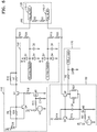
- FIG. 6 is a view illustrating an example of the apparatus 100 for verifying electrical connectivity according to an embodiment.
- the apparatus 100 for verifying electrical connectivity may include: a signal generator 110 configured to generate a first signal having a given voltage waveform under the control of a processor 140 (refer to FIG. 1 ); a second device connection unit 120 configured to transmit the first signal to a second device 300 (refer to FIG. 1 ) and acquire a second signal output from the second device 300 in response to the first signal; a processor connection unit 150 configured to transmit the first and second signals to the processor 140 (refer to FIG. 1 ); a current controller 130 configured to control the magnitude of current of the first signal such that the first signal may have a given current value; and a current monitoring unit 170 configured to deliver the current value controlled by the current controller 130 to the processor 140.
- the second device connection unit 120 may include a signal transmission unit 120-1 configured to transmit the first signal to the second device 300 (refer to FIG. 1 ), and a signal acquisition unit 120-2 configured to acquire the second signal from the second device 300 (refer to FIG. 1 ).
- the signal transmission unit 120-1 and the signal acquisition unit 120-2 may be coupled together within the second device connection unit 120 by a high impedance coupling (e.g. a high value resistor).
- a high impedance coupling e.g. a high value resistor
- Such a coupling may permit an attenuated version of the first voltage signal transmitted from 120-1 to be coupled to the signal acquisition unit 120-2 even in the absence of a connection via the second device 300.
- any such signal will be significantly attenuated, and will therefore be readily distinguished from the second signal output from the second device 300 in response to the first signal.
- the electrical connectivity between the two electronic devices may be more securely verified.
- a signal having a voltage waveform when used for verifying the electrical connectivity between two devices, even the current value of the signal may be controlled for more secure verification of the electrical connectivity between the two devices.
- the apparatus 100 for verifying electrical connectivity may be manufactured with low manufacturing costs.
Landscapes
- Engineering & Computer Science (AREA)
- Power Engineering (AREA)
- Physics & Mathematics (AREA)
- General Physics & Mathematics (AREA)
- Life Sciences & Earth Sciences (AREA)
- Sustainable Development (AREA)
- Sustainable Energy (AREA)
- Transportation (AREA)
- Mechanical Engineering (AREA)
- Chemical & Material Sciences (AREA)
- Chemical Kinetics & Catalysis (AREA)
- Electrochemistry (AREA)
- General Chemical & Material Sciences (AREA)
- Testing Of Short-Circuits, Discontinuities, Leakage, Or Incorrect Line Connections (AREA)
- Electric Cable Installation (AREA)
Description
- One or more embodiments relate to an apparatus for verifying electrical connectivity.
- With the development of electric vehicles, energy storage device technology, and the like, technologies relating to battery packs have advanced, and there is a trend toward designing battery packs having higher operating voltage and capacity for driving such devices.
- As described above, since battery packs are designed to have high voltage and capacity, it has become more important to verify whether the electrical connection between a battery pack and a device is complete. Prior art
US2010/182155 ,US2007/216356 , andUS2009/237035 teach circuits for determining whether a battery is connected to a charger. Prior artUS2015/309118 teaches a circuit for determining the state of a safety plug in a battery. Prior artUS2016/069945 discloses a circuit for determining a faulty connection in a car battery. Prior artUS2016/238665 discloses a circuit for measuring the resistance of a battery connector. - One or more embodiments include an apparatus for securely verifying the electrical connectivity between two electronic devices to be coupled to each other.
- One or more embodiments include an apparatus for securely verifying the electrical connectivity between two devices while preventing a signal used for the verification from being distorted, or at least reducing the extent to which it is distorted, by noise generated from at least one of the two devices.
- One or more embodiments include an apparatus configured to be manufactured with lower costs for verifying electrical connectivity.
- Additional aspects will be set forth in part in the description which follows and, in part, will be apparent from the description, or may be learned by practice of the presented embodiments.
- According to one or more embodiments, there is provided an apparatus for verifying electrical connectivity between a first device and a second device, the apparatus including: a signal generator configured to generate a first signal having a voltage waveform, under control of a processor; a second device connection unit configured to transmit the first signal to the second device and acquire a second signal output from the second device in response to the first signal; a processor connection unit configured to transmit the first and second signals to the processor; a current controller configured to control a magnitude of current such that the first signal has a given current value; and the processor configured to verify the electrical connectivity between the first and second devices based on the first and second signals received through the processor connection unit.
- The given current value may be greater than a current value caused by, or expected to be caused by, noise. Said noise may be noise generated by the first device and/or the second device.
- The first device may comprise said apparatus. The apparatus may be the first device. The apparatus may be included in the first device. The apparatus may be configured to verify electrical connectivity between the apparatus and the second device.
- When the first and second signals received through the processor connection unit correspond to each other, the processor may be configured to determine that the electrical connectivity between the first and second devices is verified.
- The first signal may have a predetermined characteristic. When the second signal has the predetermined characteristic, the processor may be configured to determine that the electrical connectivity between the first and second devices is verified.
- The first signal may be a time-varying waveform having said predetermined characteristic. When the second signal is a time-varying waveform having said predetermined characteristic, the processor may be configured to determine that the electrical connectivity between the first and second devices is verified. The time-varying waveform may be a square-wave signal. The predetermined characteristic may be a period.
- The first signal may be a square-wave signal having a given period, and when the second signal is a square-wave signal having the given period, the processor may be configured to determine that the electrical connectivity between the first and second devices is verified.
- The first signal may be at least one of a square-wave signal having a given period and a linear signal having only a power supply voltage, and when the second signal is a linear signal having only a ground voltage, the processor may be configured to determine that the first and second devices are in one of a state in which the first and second devices are electrically disconnected from one another and a state in which the second device is shorted to ground.
- The first signal may be at least one of a time varying waveform having a predetermined characteristic and a linear signal having only a power supply voltage, and when the second signal is a linear signal having only a ground voltage, the processor may be configured to determine that the first and second devices are in one of a state in which the first and second devices are electrically disconnected from one another and a state in which the second device is shorted to ground.
- The first signal may be a square-wave signal having a given period, and when the second signal is a linear signal having only a power supply voltage, the processor may be configured to determine that the second device is shorted to a power supply.
- The first signal may be a time varying waveform having a predetermined characteristic, and when the second signal is a linear signal having only a power supply voltage, the processor may be configured to determine that the second device is shorted to a power supply.
- The second device connection unit may include: a signal transmission unit configured to transmit the first signal to the second device; and a signal acquisition unit configured to acquire the second signal from the second device.
- The second device may form a first closed circuit having the signal transmission unit and the signal acquisition unit as a start point and an end point, respectively. The apparatus may be configured to cause the first signal to be transmitted through a second closed circuit in which the signal generator, the signal transmission unit, the first closed circuit, the signal acquisition unit, and the current controller are connected in series to each other.
- When the first signal is transmitted through the second closed circuit, the current controller may be configured to adjust a current value in the second closed circuit to be equal to the given current value.
- When the first signal is transmitted through the second closed circuit, the given current value may be greater than a current value caused by noise.
- When the first signal is transmitted through the second closed circuit, the given current value may be greater than a current value expected to be caused by noise.
- The first device may be a battery pack, and the second device may be an electronic device configured to be driven by the battery pack, wherein the apparatus may be configured to be connected in parallel to the first device and in series to the second device through the second device connection unit.
- Before the first device is connected to the second device, the apparatus may be configured to be connected in series to the second device through the second device connection unit and may verify the electrical connectivity between the first and second devices.
- According to a further embodiment there is provided a method for verifying electrical connectivity between a first device and a second device. The method comprises providing an apparatus for verifying electrical connectivity between a first device and a second device, the apparatus including: a signal generator configured to generate a first signal having a voltage waveform, under control of a processor; a second device connection unit configured to transmit the first signal to the second device and acquire a second signal output from the second device in response to the first signal; a processor connection unit configured to transmit the first and second signals to the processor; a current controller configured to control a magnitude of current such that the first signal has a given current value; and the processor configured to verify the electrical connectivity between the first and second devices based on the first and second signals received through the processor connection unit. The method further comprises causing, by the processor, the signal generator to generate the first signal having a voltage waveform; transmitting, by the second device connection unit, the first signal to the second device; acquiring, by the second device connection unit, the second signal output from the second device in response to the first signal; transmitting, by the processor connection unit, the first and second signals to the processor; controlling, by the current controller, the magnitude of current such that the first signal has the given current value; and verifying, by the processor, the electrical connectivity between the first and second devices based on the first and second signals received through the processor connection unit.
- The method may further comprise connecting the apparatus in parallel with the first device and in series with the second device through the second device connection unit.
- The method may further comprise, before the first device is connected to the second device: connecting the apparatus in series to the second device through the second device connection unit; and verifying the electrical connectivity between the first and second devices.
- It will be appreciated that features described in the context of, or in combination with, one embodiment of the present disclosure may be used in combination with other embodiments described herein. For example, features described in combination with a method described above, may be combined with the apparatus also described above, and vice versa.
- At least some of the above features that accord with the invention, and other features according to the invention, are set out in the claims.
- These and/or other aspects will become apparent and more readily appreciated from the following description of the embodiments, taken in conjunction with the accompanying drawings in which:
-
FIG. 1 is a view illustrating a configuration of an apparatus for verifying electrical connectivity, according to an embodiment; -
FIGS. 2 and3 are views illustrating a closed circuit formed by the apparatus for verifying electrical connectivity and a second device, according to an embodiment; -
FIG. 4 is a view illustrating example results of determination of the electrical connectivity between two devices according to types of first and second signals; -
FIG. 5 is view illustrating examples of first and second devices according to an embodiment; and -
FIG. 6 is a view illustrating an example of the apparatus for verifying electrical connectivity, according to an embodiment. - Reference will now be made in detail to embodiments, examples of which are illustrated in the accompanying drawings. In this regard, the present embodiments may have different forms and should not be construed as being limited to the descriptions set forth herein. Accordingly, the embodiments are merely described below, by referring to the figures, to explain aspects of the present description. As used herein, the term "and/or" includes any and all combinations of one or more of the associated listed items. Expressions such as "at least one of," when preceding a list of elements, modify the entire list of elements and do not modify the individual elements of the list.
- Advantages and features of the present disclosure, and implementation methods thereof will be clarified through the following descriptions given with reference to the accompanying drawings. However, the following embodiments of the present disclosure are non-limiting examples and may have different forms, and it should be understood that the idea and technical scope of the present disclosure cover all the modifications, equivalents, and replacements. Rather, these embodiments are provided so that this disclosure will be thorough and complete, and will fully convey the scope of the present disclosure to those skilled in the art. Moreover, detailed descriptions related to well-known functions or configurations will be omitted in order not to unnecessarily obscure subject matters of the present disclosure.
- For example, specific shapes, structures, and features described in one example embodiment may be modified in another example embodiment without departing from the scope of the present disclosure. In addition, the positions or arrangement of elements described in one example embodiment may be changed in another example embodiment within the scope of the present disclosure. That is, the following description is provided for illustrative purposes only and is not intended to limit the scope of the present disclosure. The scope of the present disclosure is defined by the claims and equivalents thereof. In the drawings, like reference numerals denote like elements. Details described in the present disclosure are examples. That is, such details may be changed in other example embodiments within the scope of the present disclosure.
- It will be understood that although the terms "first," "second," etc. may be used herein to describe various elements, these elements should not be limited by these terms. These terms are only used to distinguish one element from another.
- The terminology used herein is for explaining specific embodiments only and is not intended to limit the scope of the present disclosure. The terms of a singular form may include plural forms unless otherwise mentioned. It will be understood that terms such as "comprise," "include," and "have," when used herein, specify the presence of state features, integers, steps, operations, elements, components, or combinations thereof, but do not preclude the presence or addition of one or more other features, integers, steps, operations, elements, components, or combinations thereof.
- Hereinafter, example embodiments will be described in detail with reference to the accompanying drawings. In the drawings, like reference numerals denote like elements, and overlapping descriptions thereof will be omitted.
-
FIG. 1 is a view illustrating a configuration of anapparatus 100 for verifying electrical connectivity according to an embodiment. - The
apparatus 100 for verifying electrical connectivity according to the embodiment may verify the electrical connectivity between afirst device 200 and asecond device 300. For example, when thefirst device 200 is a battery pack and thesecond device 300 is an electronic device configured to be driven by the battery pack, theapparatus 100 for verifying electrical connectivity may verify the electrical connectivity between thefirst device 200 and thesecond device 300 before the first device 200 (battery pack) is turned on, to prevent accidents that may occur as thefirst device 200 and thesecond device 300 are connected to each other. Theapparatus 100 may comprise thefirst device 200. Theapparatus 100 may be included in thefirst device 200. Thus, by verifying a connection between theapparatus 100 and thesecond device 300 it is possible to, in effect, verify a connection between thefirst device 200 and thesecond device 300. - As shown in
FIG. 1 , theapparatus 100 for verifying electrical connectivity may include asignal generator 110, a seconddevice connection unit 120, acurrent controller 130, aprocessor 140, and aprocessor connection unit 150. - In addition, the
apparatus 100 for verifying electrical connectivity according to the embodiment may be electrically connected to the first andsecond devices second devices FIG. 1 , theapparatus 100 for verifying electrical connectivity may be connected in parallel to thefirst device 200 and in series to thesecond device 300. It will be understood that theapparatus 100 may be connected to terminals of the first device in such a way that theapparatus 100 may interact with thesecond device 300 independently of the components of the first device 200 (or other components of the first device, where theapparatus 100 is within the first device 200). That is, electrical signals are not required to pass through components of thefirst device 200 when travelling between theapparatus 100 and thesecond device 300. However, signals which are transmitted from theapparatus 100 to thesecond device 300 will pass through some part of thesecond device 300 before passing back to theapparatus 100, meaning that a series circuit is formed. - According to the embodiment, the
signal generator 110 may generate a first signal having a given voltage waveform under the control of the processor 140 (described later). At this time, the first signal generated by thesignal generator 110 may be transmitted through a closed circuit formed by theapparatus 100 for verifying electrical connectivity and thesecond device 300. The closed circuit will be described later. - In addition, the
signal generator 110 may generate first signals having various voltage waveforms under the control of the processor 140 (described later). For example, as shown inFIG. 4 , thesignal generator 110 may generate a square-wave signal having a given period, or a linear signal having only a power supply voltage or ground voltage. However, the above-described forms of first signals are examples, and embodiments are not limited thereto. For example, a square-wave signal having a given period may be considered to be an example of a time-varying waveform having a given period. Further, a time-varying waveform having a given period may itself be considered to be an example of a time-varying waveform having a predetermined characteristic. In general terms, thesignal generator 110 may generate a time-varying waveform having a predetermined characteristic. More generally still, thesignal generator 110 may generate the first signal so as to cause the first signal to have a predetermined characteristic. - The second
device connection unit 120 of the embodiment may transmit a first signal generated by thesignal generator 110 to thesecond device 300 and may acquire a second signal output from thesecond device 300 in response to the first signal. To this end, the seconddevice connection unit 120 of the embodiment may include: a signal transmission unit 120-1 (refer toFIG. 3 ) configured to transmit a first signal generated by thesignal generator 110 to thesecond device 300; and a signal acquisition unit 120-2 (refer toFIG. 3 ) configured to acquire a second signal output from thesecond device 300 in response to the first signal. - The
processor connection unit 150 of the embodiment may be configured to enable monitoring of the first signal and the second signal. For example, as illustrated inFig. 1 , theprocessor connection unit 150 may be configured to enable monitoring of the first signal between thesignal generator 110 and the seconddevice connection unit 120. Theprocessor connection unit 150 may be further configured to enable monitoring of the second signal between the seconddevice connection unit 120 and thecurrent controller 130. Theprocessor connection unit 150 may transmit the first signal and the second signal to theprocessor 140. In this case, the first and second signals transmitted to theprocessor 140 through theprocessor connection unit 150 may be used to check the electrical connectivity between thefirst device 200 and thesecond device 300. - The
current controller 130 of the embodiment may operate such that the first signal having a voltage waveform and transmitted through the closed circuit formed by theapparatus 100 for verifying electrical connectivity and thesecond device 300 may have a current value. For example, the current controller may comprise a current source or sink (e.g. comprising a current mirror), configured to cause a current having a predetermined magnitude to flow from thesignal generator 110 to thecurrent controller 130 along a circuit which is described in more detail below. - In the related art, when the electrical connectivity between the
first device 200 and thesecond device 300 are verified, only the voltage of the signal is considered, and thus the electrical connectivity between thefirst device 200 and thesecond device 300 may not be properly verified due to the influence of noise. - However, according to the embodiment, the
apparatus 100 for verifying electrical connectivity uniformly controls even the current value of the first signal having a given voltage waveform. Therefore, the influence of noise may be reduced, and thus the electrical connectivity between two devices may be more reliably verified. That is, by causing the first signal to have a current value (e.g. a predetermined current magnitude value), the risk that noise is of greater magnitude than the first signal may be reduced. It will, of course, be appreciated that an appropriate current value may be selected by the skilled person based upon the expected noise level of a particular system. - The
processor 140 of the embodiment may check the electrical connectivity between thefirst device 200 and thesecond device 300 based on the first signal and the second signal transmitted through theprocessor connection unit 150. For example, when the first signal and the second signal transmitted through theprocessor connection unit 150 correspond to each other, theprocessor 140 may determine that the electrical connectivity between thefirst device 200 and thesecond device 300 is verified. In this case, the expression "two signals 'correspond to' each other" may mean that the two signals are identical to each other or are within the range in which the two signals are considered to be identical to each other. Alternatively, or in addition, when the first signal and the second signal transmitted through theprocessor connection unit 150 both comprise a predetermined characteristic, theprocessor 140 may determine that the electrical connectivity between thefirst device 200 and thesecond device 300 is verified. - The
processor 140 may control the voltage waveform of the first signal generated by thesignal generator 110 as described above. - For example, the
processor 140 may refer to a data processing device included in hardware and having a physically structured circuit to execute codes of programs or functions expressed with instructions. Examples of the data processing device included in hardware may include a microprocessor, a central processing unit (CPU), a processor core, a multiprocessor, an application-specific integrated circuit (ASIC), and a field programmable gate array (FPGA). However, embodiments are not limited thereto. - In an alternative embodiment, the
processor 140 may be a device included in thefirst device 200. For example, thefirst device 200 may be a battery pack, and theprocessor 140 may be a device included in a battery management system (BMS) of the battery pack or may be the BMS. However, this is an example, and embodiments are not limited thereto. Theapparatus 100 may be provided within thefirst device 200. -
FIGS. 2 and3 are views illustrating aclosed circuit 160 formed by theapparatus 100 for verifying electrical connectivity and thesecond device 300 according to an embodiment. - As described above, a first signal generated by the
signal generator 110 may be transmitted to thesecond device 300 through the seconddevice connection unit 120, and a second signal output from thesecond device 300 in response to the first signal may be transmitted back to theapparatus 100 for verifying electrical connectivity through the seconddevice connection unit 120. - In other words, the first signal may be transmitted through the
closed circuit 160 formed by thesignal generator 110, the seconddevice connection unit 120, and thesecond device 300. In this case, thecurrent controller 130 placed in theclosed circuit 160 may maintain the magnitude of current of the first signal at a constant level in theclosed circuit 160. - This will now be described with reference to
FIG. 3 . The first signal may be transmitted through theclosed circuit 160 formed by thesignal generator 110, the signal transmission unit 120-1 of the seconddevice connection unit 120, thesecond device 300, the signal acquisition unit 120-2 of the seconddevice connection unit 120, and thecurrent controller 130. - It will be understood that at least two connections may be made at each of the
apparatus 100 and thesecond device 300. For example, a first connection may be made to the signal transmission unit 120-1 of the seconddevice connection unit 120, and a second connection may be made to the signal acquisition unit 120-2 of the seconddevice connection unit 120. At the second device, a first connection may be made which receives the signal transmitted from the signal transmission unit 120-1, and a second connection may be made which emits the signal back to the signal acquisition unit 120-2. As such, there may be provided two independent connections between theapparatus 100 and thesecond device 300. It will be understood that the connections will be made to theapparatus 100 at at least two separate connection points or terminals, and to thesecond device 300 at at least two separate connection points or terminals. - In this case, the
current controller 130 may maintain the magnitude of current of the first signal such that the current value of the first signal may be less affected bynoise 310 generated in thesecond device 300, and thus the electrical connectivity between the first andsecond devices -
FIG. 4 illustrates example results of determination of the electrical connectivity between the first andsecond devices - As described above, when first and second signals received through the
processor connection unit 150 correspond to each other, theprocessor 140 may determine that the electrical connectivity between thefirst device 200 and thesecond device 300 is verified. In this case, the expression "two signals 'correspond to' each other" may mean that the two signals are identical to each other or are within the range in which the two signals are considered to be identical to each other, or substantially identical to each other. - When the first signal is a square-wave signal having a given period and the second signal is also a square-wave signal having the same period as the first signal, the
processor 140 may determine that the electrical connectivity between thefirst device 200 and thesecond device 300 is verified. Of course, when the first signal is a time-varying signal having a given characteristic other than a square-wave signal, theprocessor 140 may determine that the electrical connectivity between thefirst device 200 and thesecond device 300 is verified based upon the second signal also having the given characteristic. - However, when the first signal is a square-wave signal having a given period but the second signal is a linear signal having only a ground voltage, the
processor 140 may determine this situation as one of the state in which thefirst device 200 and thesecond device 300 are electrically opened (i.e. disconnected from one another) and the state in which thesecond device 300 is shorted to ground. - In addition, similarly, when the first signal is a square-wave signal having a given period but the second signal is a linear signal having only a power supply voltage, the
processor 140 may determine that thesecond device 300 is shorted to a power supply. In this case, the ground voltage may refer to one of a ground voltage and a reference voltage, and the power supply voltage may refer to the voltage of the power supply used to drive thefirst device 200 and/or theapparatus 100. - In addition, when the first signal is a linear signal having only the power supply voltage and the second signal is a linear signal having only the ground voltage, the
processor 140 may determine this situation as one of the state in which thefirst device 200 and thesecond device 300 are electrically opened (i.e. disconnected from one another) and the state in which thesecond device 300 is shorted to ground. - Conversely, when the first signal is a linear signal having only the ground voltage and the second signal is a linear signal having only the power supply voltage, the
processor 140 may determine that thesecond device 300 is shorted to the power supply. - It will be understood that the coupling within the
second device 300 between the connection points of thesecond device 300 will have an impact upon the nature of the similarity between the first and second signals. For example, if the two the connection points are connected together within the second device 300 (and not also shorted to ground/a power supply), the second signal will generally be the same as the first signal. However, if the two the connection points are isolated from one another within thesecond device 300, the second signal will generally be independent from the first signal and will not allow the electrical connectivity between the first andsecond devices - In this manner, the
processor 140 of the embodiment may variously verify the electrical connectivity between the first andsecond devices -
FIG. 5 is view illustrating examples of thefirst device 200 and thesecond device 300 according to an embodiment. - As shown in
FIG. 5 , for example, thefirst device 200 may be a battery pack, and thesecond device 300 may be a cart configured to be driven by the battery pack. While shown separately, theapparatus 100 may be provided within, or as part of, thefirst device 200. - In this case, before the
first device 200 is connected to thesecond device 300, theapparatus 100 for verifying electrical connectivity may be connected in series to thesecond device 300 to verify the electrical connectivity between thefirst device 200 and thesecond device 300. - In other words, the
apparatus 100 for verifying electrical connectivity may transmit afirst signal 410 to thesecond device 300 and may acquire a second signal 420 output from thesecond device 300 in response to thefirst signal 410 to verify the electrical connectivity between the first andsecond devices second signals 410 and 420. - Furthermore, in the present disclosure, the expression "before the
first device 200 is connected to thesecond device 300" may mean that the system is in a state in which wiring for connecting thefirst device 200 and thesecond device 300 to each other is set up as shown inFIG. 5 , but that thefirst device 200 and thesecond device 300 are not yet electrically connected to each other because an internal switch of thefirst device 200 is turned off. -
FIG. 6 is a view illustrating an example of theapparatus 100 for verifying electrical connectivity according to an embodiment. - As described above, the
apparatus 100 for verifying electrical connectivity may include: asignal generator 110 configured to generate a first signal having a given voltage waveform under the control of a processor 140 (refer toFIG. 1 ); a seconddevice connection unit 120 configured to transmit the first signal to a second device 300 (refer toFIG. 1 ) and acquire a second signal output from thesecond device 300 in response to the first signal; aprocessor connection unit 150 configured to transmit the first and second signals to the processor 140 (refer toFIG. 1 ); acurrent controller 130 configured to control the magnitude of current of the first signal such that the first signal may have a given current value; and acurrent monitoring unit 170 configured to deliver the current value controlled by thecurrent controller 130 to theprocessor 140. - In this case, as described above, the second
device connection unit 120 may include a signal transmission unit 120-1 configured to transmit the first signal to the second device 300 (refer toFIG. 1 ), and a signal acquisition unit 120-2 configured to acquire the second signal from the second device 300 (refer toFIG. 1 ). The signal transmission unit 120-1 and the signal acquisition unit 120-2 may be coupled together within the seconddevice connection unit 120 by a high impedance coupling (e.g. a high value resistor). Such a coupling may permit an attenuated version of the first voltage signal transmitted from 120-1 to be coupled to the signal acquisition unit 120-2 even in the absence of a connection via thesecond device 300. However, it will be understood that any such signal will be significantly attenuated, and will therefore be readily distinguished from the second signal output from thesecond device 300 in response to the first signal. - As described above, according to the one or more of the above embodiments, when two electronic devices are coupled, the electrical connectivity between the two electronic devices may be more securely verified.
- In particular, according to the present disclosure, when a signal having a voltage waveform is used for verifying the electrical connectivity between two devices, even the current value of the signal may be controlled for more secure verification of the electrical connectivity between the two devices.
- In addition, according to the present disclosure, the
apparatus 100 for verifying electrical connectivity may be manufactured with low manufacturing costs. - It should be understood that embodiments described herein should be considered in a descriptive sense only and not for purposes of limitation. Descriptions of features or aspects within each embodiment should typically be considered as available for other similar features or aspects in other embodiments.
- While one or more embodiments have been described with reference to the figures, it will be understood by those of ordinary skill in the art that various changes in form and details may be made therein without departing from the scope of the invention, which is defined by the following claims.
Claims (15)
- An apparatus (100) for verifying electrical connectivity between a first device (200) and a second device (300), the apparatus comprising:a signal generator (110) configured to generate a first signal having a voltage waveform;a processor (140) configured to control the signal generator;a second device connection unit (120) configured to transmit the first signal to the second device and acquire a second signal output from the second device in response to the first signal;a processor connection unit (150) configured to transmit the first and second signals to the processor;a current controller (130) configured to control a magnitude of current such that the first signal has a given current value; andthe processor configured to verify the electrical connectivity between the first and second devices based on the first and second signals received through the processor connection unit.
- The apparatus of claim 1, wherein, when the first and second signals received through the processor connection unit correspond to each other, the processor is configured to determine that the electrical connectivity between the first and second devices is verified.
- The apparatus of claim 2, wherein the first signal has a predetermined characteristic, and when the second signal has the predetermined characteristic, the processor is configured to determine that the electrical connectivity between the first and second devices is verified.
- The apparatus of claim 3, wherein the first signal is a time-varying waveform having said predetermined characteristic, and
when the second signal is a time-varying waveform having said predetermined characteristic, the processor is configured to determine that the electrical connectivity between the first and second devices is verified. - The apparatus of any preceding claim, wherein the first signal is a square-wave signal having a given period, and
when the second signal is a square-wave signal having the given period, the processor is configured to determine that the electrical connectivity between the first and second devices is verified. - The apparatus of any preceding claim, wherein the first signal is at least one of a time varying waveform having a predetermined characteristic and a linear signal having only a power supply voltage, and
when the second signal is a linear signal having only a ground voltage, the processor is configured to determine that the first and second devices are in one of a state in which the first and second devices are electrically disconnected from one another and a state in which the second device is shorted to ground. - The apparatus of any preceding claim, wherein the first signal is a time varying waveform having a predetermined characteristic, and
when the second signal is a linear signal having only a power supply voltage, the processor is configured to determine that the second device is shorted to a power supply. - The apparatus of claim any preceding claim, wherein the second device connection unit comprises:a signal transmission unit configured to transmit the first signal to the second device; anda signal acquisition unit configured to acquire the second signal from the second device,wherein the second device forms a first closed circuit having the signal transmission unit and the signal acquisition unit as a start point and an end point, respectively,wherein the apparatus is configured to cause the first signal to be transmitted through a second closed circuit in which the signal generator, the signal transmission unit, the first closed circuit, the signal acquisition unit, and the current controller are connected in series to each other.
- The apparatus of claim 8, wherein, when the first signal is transmitted through the second closed circuit, the current controller is configured to adjust a current value in the second closed circuit to be equal to the given current value.
- The apparatus of claim 9, wherein, when the first signal is transmitted through the second closed circuit, the given current value is greater than a current value caused by noise.
- The apparatus of claim any preceding claim, wherein
the first device is a battery pack, and
the second device is an electronic device configured to be driven by the battery pack,
wherein the apparatus is configured to be connected in parallel to the first device and in series to the second device through the second device connection unit. - The apparatus of claim 11, wherein, before the first device is connected to the second device, the apparatus is configured to be connected in series to the second device through the second device connection unit and to verify the electrical connectivity between the first and second devices.
- A method for verifying electrical connectivity between a first device and a second device, comprising:providing an apparatus according to any preceding claim;causing, by the processor, the signal generator to generate the first signal having a voltage waveform;transmitting, by the second device connection unit, the first signal to the second device;acquiring, by the second device connection unit, the second signal output from the second device in response to the first signal;transmitting, by the processor connection unit, the first and second signals to the processor;controlling, by the current controller, the magnitude of current such that the first signal has the given current value; andverifying, by the processor, the electrical connectivity between the first and second devices based on the first and second signals received through the processor connection unit.
- The method of claim 13, further comprising connecting the apparatus in parallel with the first device and in series with the second device through the second device connection unit.
- The method of claim 14, further comprising, before the first device is connected to the second device:connecting the apparatus in series to the second device through the second device connection unit; andverifying the electrical connectivity between the first and second devices.
Priority Applications (1)
| Application Number | Priority Date | Filing Date | Title |
|---|---|---|---|
| PL19176417T PL3581948T3 (en) | 2018-05-25 | 2019-05-24 | ELECTRICAL CONNECTION VERIFICATION DEVICE |
Applications Claiming Priority (1)
| Application Number | Priority Date | Filing Date | Title |
|---|---|---|---|
| KR1020180059581A KR102449128B1 (en) | 2018-05-25 | 2018-05-25 | Electrical Connectivity Verification Device |
Publications (2)
| Publication Number | Publication Date |
|---|---|
| EP3581948A1 EP3581948A1 (en) | 2019-12-18 |
| EP3581948B1 true EP3581948B1 (en) | 2021-02-24 |
Family
ID=66647241
Family Applications (1)
| Application Number | Title | Priority Date | Filing Date |
|---|---|---|---|
| EP19176417.4A Active EP3581948B1 (en) | 2018-05-25 | 2019-05-24 | Apparatus for verifying electrical connectivity |
Country Status (5)
| Country | Link |
|---|---|
| US (1) | US11579199B2 (en) |
| EP (1) | EP3581948B1 (en) |
| KR (1) | KR102449128B1 (en) |
| HU (1) | HUE054978T2 (en) |
| PL (1) | PL3581948T3 (en) |
Families Citing this family (2)
| Publication number | Priority date | Publication date | Assignee | Title |
|---|---|---|---|---|
| CN113169411A (en) * | 2020-08-19 | 2021-07-23 | 深圳市大疆创新科技有限公司 | Battery device, control circuit, power-supplied device, and electronic apparatus |
| KR102682917B1 (en) | 2020-10-16 | 2024-07-05 | 삼성에스디아이 주식회사 | Connection test apparatus |
Family Cites Families (18)
| Publication number | Priority date | Publication date | Assignee | Title |
|---|---|---|---|---|
| JP4533328B2 (en) | 2006-02-28 | 2010-09-01 | 株式会社リコー | CHARGE CONTROL SEMICONDUCTOR INTEGRATED CIRCUIT, CHARGING DEVICE USING THE CHARGE CONTROL SEMICONDUCTOR INTEGRATED CIRCUIT, AND SECONDARY BATTERY CONNECTION DETECTION METHOD |
| TW200940962A (en) | 2008-03-18 | 2009-10-01 | Richtek Technology Corp | Circuit and method for detecting absent battery condition |
| KR101539237B1 (en) | 2009-01-20 | 2015-07-27 | 삼성전자주식회사 | Battery loading detection device and detection method |
| US8824113B2 (en) | 2010-03-15 | 2014-09-02 | International Truck Intellectual Property Company, Llc | High voltage interlock circuit utilizing serial communications |
| WO2012072024A1 (en) * | 2010-11-30 | 2012-06-07 | 苏州宝时得电动工具有限公司 | Automatic walking device, charging station, docking system and docking method |
| DE102011004281B4 (en) | 2011-02-17 | 2024-12-19 | Robert Bosch Gmbh | Method for monitoring a battery pack, battery with a monitoring module and a motor vehicle with a corresponding battery |
| CN103187777B (en) * | 2011-12-28 | 2016-04-27 | 比亚迪股份有限公司 | A kind of charger and detection method |
| KR102004310B1 (en) | 2012-11-12 | 2019-07-30 | 에스케이이노베이션 주식회사 | Apparatus and method for connector monitoring of hybrid or electric vehicle |
| CN103762690B (en) * | 2014-01-28 | 2016-08-24 | 广东欧珀移动通信有限公司 | Charging system |
| US10199921B2 (en) | 2014-04-03 | 2019-02-05 | Semiconductor Components Industries, Llc | Load detecting device |
| KR102159251B1 (en) * | 2014-04-03 | 2020-09-23 | 온세미컨덕터코리아 주식회사 | Load detecting device |
| KR102171102B1 (en) | 2014-04-23 | 2020-10-28 | 삼성전자주식회사 | Method and apparatus for detecting condition of safety plug |
| FR3025607B1 (en) | 2014-09-10 | 2016-09-16 | Continental Automotive France | METHOD FOR DETECTING A CONNECTION FAULT OF AN AUXILIARY BATTERY |
| KR102291154B1 (en) | 2014-10-29 | 2021-08-19 | 현대모비스 주식회사 | Apparatus Checking Connection of Power Connector for Vehicle |
| US10389280B2 (en) | 2014-12-02 | 2019-08-20 | Ford Global Technologies, Llc | High frequency injection-based high voltage interlock |
| US10114060B2 (en) | 2015-02-16 | 2018-10-30 | Continental Automotive Systems, Inc. | Negative battery main contactor status determination |
| US10411488B2 (en) * | 2016-05-02 | 2019-09-10 | Club Car, Llc | Onboard battery charging system |
| KR101836740B1 (en) * | 2016-11-28 | 2018-03-09 | 현대자동차주식회사 | Apparatus for detecting open/close state of control pilot line of on-board charger |
-
2018
- 2018-05-25 KR KR1020180059581A patent/KR102449128B1/en active Active
-
2019
- 2019-05-21 US US16/418,921 patent/US11579199B2/en active Active
- 2019-05-24 EP EP19176417.4A patent/EP3581948B1/en active Active
- 2019-05-24 PL PL19176417T patent/PL3581948T3/en unknown
- 2019-05-24 HU HUE19176417A patent/HUE054978T2/en unknown
Non-Patent Citations (1)
| Title |
|---|
| None * |
Also Published As
| Publication number | Publication date |
|---|---|
| HUE054978T2 (en) | 2021-10-28 |
| KR102449128B1 (en) | 2022-09-29 |
| PL3581948T3 (en) | 2021-07-26 |
| US20190363558A1 (en) | 2019-11-28 |
| EP3581948A1 (en) | 2019-12-18 |
| KR20190134215A (en) | 2019-12-04 |
| US11579199B2 (en) | 2023-02-14 |
Similar Documents
| Publication | Publication Date | Title |
|---|---|---|
| US9114715B2 (en) | Electronic control unit | |
| US9851387B2 (en) | HVIL signal generator and detector with loop diagnostics | |
| CN103250061B (en) | Insulation resistance measurement circuit having self-est function without generating leakage current | |
| US6970807B2 (en) | Diagnostic system and method for electric leak detecting device | |
| US9662989B2 (en) | Fault diagnostic device for vehicle charging system | |
| US10451664B2 (en) | Interconnect device for detecting whether a vehicle on-board diagnostics (OBD) data port includes circuitry which prevents back feeding of power through the OBD data port | |
| CN103562000B (en) | For the system of charging to electronic or motor vehicle driven by mixed power | |
| TWI555300B (en) | Electric leakage protection device and power supply control device | |
| KR102004310B1 (en) | Apparatus and method for connector monitoring of hybrid or electric vehicle | |
| CN109017310B (en) | High voltage shield based interlock for vehicles | |
| US20180300967A1 (en) | Apparatus and Method for Monitoring Vehicle ON/OFF State | |
| CN111164442B (en) | System and method for diagnosing power failure | |
| KR20130127945A (en) | Semiconductor device and voltage measuring device | |
| EP3581948B1 (en) | Apparatus for verifying electrical connectivity | |
| US20180190458A1 (en) | Relay control circuit | |
| KR101142461B1 (en) | Insulation resistance measurement circuit | |
| KR20160037982A (en) | Battery-monitoring unit | |
| US10274540B2 (en) | Method for identifying the existence of a failure, method for identifying a failed relay device, method for identifying the type of failure and associated power supply system | |
| KR102291762B1 (en) | Circuit for diagnosing a relay | |
| CN114026445A (en) | Apparatus and method for monitoring electrical safety interlocks | |
| JP2010536641A (en) | Monitoring device for monitoring the connection of connecting parts | |
| JP6623794B2 (en) | Relay sticking detection system | |
| KR20160050365A (en) | Apparatus Checking Connection of Power Connector for Vehicle | |
| US10012703B2 (en) | Battery charger module for charging a vehicle battery and method for determining a state of an AC power supply at a battery charger module | |
| TWI754843B (en) | Charging device for electric vehicle |
Legal Events
| Date | Code | Title | Description |
|---|---|---|---|
| PUAI | Public reference made under article 153(3) epc to a published international application that has entered the european phase |
Free format text: ORIGINAL CODE: 0009012 |
|
| STAA | Information on the status of an ep patent application or granted ep patent |
Free format text: STATUS: REQUEST FOR EXAMINATION WAS MADE |
|
| 17P | Request for examination filed |
Effective date: 20190524 |
|
| AK | Designated contracting states |
Kind code of ref document: A1 Designated state(s): AL AT BE BG CH CY CZ DE DK EE ES FI FR GB GR HR HU IE IS IT LI LT LU LV MC MK MT NL NO PL PT RO RS SE SI SK SM TR |
|
| AX | Request for extension of the european patent |
Extension state: BA ME |
|
| REG | Reference to a national code |
Ref country code: DE Ref legal event code: R079 Ref document number: 602019002713 Country of ref document: DE Free format text: PREVIOUS MAIN CLASS: G01R0031040000 Ipc: G01R0031360000 |
|
| GRAP | Despatch of communication of intention to grant a patent |
Free format text: ORIGINAL CODE: EPIDOSNIGR1 |
|
| STAA | Information on the status of an ep patent application or granted ep patent |
Free format text: STATUS: GRANT OF PATENT IS INTENDED |
|
| RIC1 | Information provided on ipc code assigned before grant |
Ipc: G01R 31/67 20200101ALI20200821BHEP Ipc: G01R 31/36 20200101AFI20200821BHEP |
|
| INTG | Intention to grant announced |
Effective date: 20200917 |
|
| GRAS | Grant fee paid |
Free format text: ORIGINAL CODE: EPIDOSNIGR3 |
|
| GRAA | (expected) grant |
Free format text: ORIGINAL CODE: 0009210 |
|
| STAA | Information on the status of an ep patent application or granted ep patent |
Free format text: STATUS: THE PATENT HAS BEEN GRANTED |
|
| AK | Designated contracting states |
Kind code of ref document: B1 Designated state(s): AL AT BE BG CH CY CZ DE DK EE ES FI FR GB GR HR HU IE IS IT LI LT LU LV MC MK MT NL NO PL PT RO RS SE SI SK SM TR |
|
| REG | Reference to a national code |
Ref country code: CH Ref legal event code: EP |
|
| REG | Reference to a national code |
Ref country code: DE Ref legal event code: R096 Ref document number: 602019002713 Country of ref document: DE |
|
| REG | Reference to a national code |
Ref country code: AT Ref legal event code: REF Ref document number: 1365156 Country of ref document: AT Kind code of ref document: T Effective date: 20210315 |
|
| REG | Reference to a national code |
Ref country code: IE Ref legal event code: FG4D |
|
| REG | Reference to a national code |
Ref country code: LT Ref legal event code: MG9D |
|
| REG | Reference to a national code |
Ref country code: NL Ref legal event code: MP Effective date: 20210224 |
|
| PG25 | Lapsed in a contracting state [announced via postgrant information from national office to epo] |
Ref country code: NO Free format text: LAPSE BECAUSE OF FAILURE TO SUBMIT A TRANSLATION OF THE DESCRIPTION OR TO PAY THE FEE WITHIN THE PRESCRIBED TIME-LIMIT Effective date: 20210524 Ref country code: PT Free format text: LAPSE BECAUSE OF FAILURE TO SUBMIT A TRANSLATION OF THE DESCRIPTION OR TO PAY THE FEE WITHIN THE PRESCRIBED TIME-LIMIT Effective date: 20210624 Ref country code: LT Free format text: LAPSE BECAUSE OF FAILURE TO SUBMIT A TRANSLATION OF THE DESCRIPTION OR TO PAY THE FEE WITHIN THE PRESCRIBED TIME-LIMIT Effective date: 20210224 Ref country code: HR Free format text: LAPSE BECAUSE OF FAILURE TO SUBMIT A TRANSLATION OF THE DESCRIPTION OR TO PAY THE FEE WITHIN THE PRESCRIBED TIME-LIMIT Effective date: 20210224 Ref country code: BG Free format text: LAPSE BECAUSE OF FAILURE TO SUBMIT A TRANSLATION OF THE DESCRIPTION OR TO PAY THE FEE WITHIN THE PRESCRIBED TIME-LIMIT Effective date: 20210524 Ref country code: GR Free format text: LAPSE BECAUSE OF FAILURE TO SUBMIT A TRANSLATION OF THE DESCRIPTION OR TO PAY THE FEE WITHIN THE PRESCRIBED TIME-LIMIT Effective date: 20210525 Ref country code: FI Free format text: LAPSE BECAUSE OF FAILURE TO SUBMIT A TRANSLATION OF THE DESCRIPTION OR TO PAY THE FEE WITHIN THE PRESCRIBED TIME-LIMIT Effective date: 20210224 |
|
| REG | Reference to a national code |
Ref country code: AT Ref legal event code: MK05 Ref document number: 1365156 Country of ref document: AT Kind code of ref document: T Effective date: 20210224 |
|
| PG25 | Lapsed in a contracting state [announced via postgrant information from national office to epo] |
Ref country code: SE Free format text: LAPSE BECAUSE OF FAILURE TO SUBMIT A TRANSLATION OF THE DESCRIPTION OR TO PAY THE FEE WITHIN THE PRESCRIBED TIME-LIMIT Effective date: 20210224 Ref country code: LV Free format text: LAPSE BECAUSE OF FAILURE TO SUBMIT A TRANSLATION OF THE DESCRIPTION OR TO PAY THE FEE WITHIN THE PRESCRIBED TIME-LIMIT Effective date: 20210224 Ref country code: RS Free format text: LAPSE BECAUSE OF FAILURE TO SUBMIT A TRANSLATION OF THE DESCRIPTION OR TO PAY THE FEE WITHIN THE PRESCRIBED TIME-LIMIT Effective date: 20210224 Ref country code: NL Free format text: LAPSE BECAUSE OF FAILURE TO SUBMIT A TRANSLATION OF THE DESCRIPTION OR TO PAY THE FEE WITHIN THE PRESCRIBED TIME-LIMIT Effective date: 20210224 |
|
| PG25 | Lapsed in a contracting state [announced via postgrant information from national office to epo] |
Ref country code: IS Free format text: LAPSE BECAUSE OF FAILURE TO SUBMIT A TRANSLATION OF THE DESCRIPTION OR TO PAY THE FEE WITHIN THE PRESCRIBED TIME-LIMIT Effective date: 20210624 |
|
| REG | Reference to a national code |
Ref country code: HU Ref legal event code: AG4A Ref document number: E054978 Country of ref document: HU |
|
| PG25 | Lapsed in a contracting state [announced via postgrant information from national office to epo] |
Ref country code: EE Free format text: LAPSE BECAUSE OF FAILURE TO SUBMIT A TRANSLATION OF THE DESCRIPTION OR TO PAY THE FEE WITHIN THE PRESCRIBED TIME-LIMIT Effective date: 20210224 Ref country code: CZ Free format text: LAPSE BECAUSE OF FAILURE TO SUBMIT A TRANSLATION OF THE DESCRIPTION OR TO PAY THE FEE WITHIN THE PRESCRIBED TIME-LIMIT Effective date: 20210224 Ref country code: SM Free format text: LAPSE BECAUSE OF FAILURE TO SUBMIT A TRANSLATION OF THE DESCRIPTION OR TO PAY THE FEE WITHIN THE PRESCRIBED TIME-LIMIT Effective date: 20210224 Ref country code: AT Free format text: LAPSE BECAUSE OF FAILURE TO SUBMIT A TRANSLATION OF THE DESCRIPTION OR TO PAY THE FEE WITHIN THE PRESCRIBED TIME-LIMIT Effective date: 20210224 |
|
| REG | Reference to a national code |
Ref country code: DE Ref legal event code: R097 Ref document number: 602019002713 Country of ref document: DE |
|
| PG25 | Lapsed in a contracting state [announced via postgrant information from national office to epo] |
Ref country code: DK Free format text: LAPSE BECAUSE OF FAILURE TO SUBMIT A TRANSLATION OF THE DESCRIPTION OR TO PAY THE FEE WITHIN THE PRESCRIBED TIME-LIMIT Effective date: 20210224 Ref country code: SK Free format text: LAPSE BECAUSE OF FAILURE TO SUBMIT A TRANSLATION OF THE DESCRIPTION OR TO PAY THE FEE WITHIN THE PRESCRIBED TIME-LIMIT Effective date: 20210224 Ref country code: RO Free format text: LAPSE BECAUSE OF FAILURE TO SUBMIT A TRANSLATION OF THE DESCRIPTION OR TO PAY THE FEE WITHIN THE PRESCRIBED TIME-LIMIT Effective date: 20210224 |
|
| PLBE | No opposition filed within time limit |
Free format text: ORIGINAL CODE: 0009261 |
|
| STAA | Information on the status of an ep patent application or granted ep patent |
Free format text: STATUS: NO OPPOSITION FILED WITHIN TIME LIMIT |
|
| PG25 | Lapsed in a contracting state [announced via postgrant information from national office to epo] |
Ref country code: ES Free format text: LAPSE BECAUSE OF FAILURE TO SUBMIT A TRANSLATION OF THE DESCRIPTION OR TO PAY THE FEE WITHIN THE PRESCRIBED TIME-LIMIT Effective date: 20210224 Ref country code: LU Free format text: LAPSE BECAUSE OF NON-PAYMENT OF DUE FEES Effective date: 20210524 Ref country code: AL Free format text: LAPSE BECAUSE OF FAILURE TO SUBMIT A TRANSLATION OF THE DESCRIPTION OR TO PAY THE FEE WITHIN THE PRESCRIBED TIME-LIMIT Effective date: 20210224 Ref country code: MC Free format text: LAPSE BECAUSE OF FAILURE TO SUBMIT A TRANSLATION OF THE DESCRIPTION OR TO PAY THE FEE WITHIN THE PRESCRIBED TIME-LIMIT Effective date: 20210224 |
|
| 26N | No opposition filed |
Effective date: 20211125 |
|
| REG | Reference to a national code |
Ref country code: BE Ref legal event code: MM Effective date: 20210531 |
|
| PG25 | Lapsed in a contracting state [announced via postgrant information from national office to epo] |
Ref country code: SI Free format text: LAPSE BECAUSE OF FAILURE TO SUBMIT A TRANSLATION OF THE DESCRIPTION OR TO PAY THE FEE WITHIN THE PRESCRIBED TIME-LIMIT Effective date: 20210224 |
|
| PG25 | Lapsed in a contracting state [announced via postgrant information from national office to epo] |
Ref country code: IT Free format text: LAPSE BECAUSE OF FAILURE TO SUBMIT A TRANSLATION OF THE DESCRIPTION OR TO PAY THE FEE WITHIN THE PRESCRIBED TIME-LIMIT Effective date: 20210224 Ref country code: IE Free format text: LAPSE BECAUSE OF NON-PAYMENT OF DUE FEES Effective date: 20210524 |
|
| PG25 | Lapsed in a contracting state [announced via postgrant information from national office to epo] |
Ref country code: IS Free format text: LAPSE BECAUSE OF FAILURE TO SUBMIT A TRANSLATION OF THE DESCRIPTION OR TO PAY THE FEE WITHIN THE PRESCRIBED TIME-LIMIT Effective date: 20210624 |
|
| PG25 | Lapsed in a contracting state [announced via postgrant information from national office to epo] |
Ref country code: BE Free format text: LAPSE BECAUSE OF NON-PAYMENT OF DUE FEES Effective date: 20210531 |
|
| REG | Reference to a national code |
Ref country code: CH Ref legal event code: PL |
|
| PG25 | Lapsed in a contracting state [announced via postgrant information from national office to epo] |
Ref country code: LI Free format text: LAPSE BECAUSE OF NON-PAYMENT OF DUE FEES Effective date: 20220531 Ref country code: CH Free format text: LAPSE BECAUSE OF NON-PAYMENT OF DUE FEES Effective date: 20220531 |
|
| PG25 | Lapsed in a contracting state [announced via postgrant information from national office to epo] |
Ref country code: CY Free format text: LAPSE BECAUSE OF FAILURE TO SUBMIT A TRANSLATION OF THE DESCRIPTION OR TO PAY THE FEE WITHIN THE PRESCRIBED TIME-LIMIT Effective date: 20210224 |
|
| P01 | Opt-out of the competence of the unified patent court (upc) registered |
Effective date: 20230528 |
|
| PG25 | Lapsed in a contracting state [announced via postgrant information from national office to epo] |
Ref country code: MK Free format text: LAPSE BECAUSE OF FAILURE TO SUBMIT A TRANSLATION OF THE DESCRIPTION OR TO PAY THE FEE WITHIN THE PRESCRIBED TIME-LIMIT Effective date: 20210224 |
|
| PG25 | Lapsed in a contracting state [announced via postgrant information from national office to epo] |
Ref country code: MT Free format text: LAPSE BECAUSE OF FAILURE TO SUBMIT A TRANSLATION OF THE DESCRIPTION OR TO PAY THE FEE WITHIN THE PRESCRIBED TIME-LIMIT Effective date: 20210224 |
|
| PGFP | Annual fee paid to national office [announced via postgrant information from national office to epo] |
Ref country code: PL Payment date: 20250507 Year of fee payment: 7 Ref country code: DE Payment date: 20250429 Year of fee payment: 7 |
|
| PGFP | Annual fee paid to national office [announced via postgrant information from national office to epo] |
Ref country code: GB Payment date: 20250501 Year of fee payment: 7 |
|
| PGFP | Annual fee paid to national office [announced via postgrant information from national office to epo] |
Ref country code: HU Payment date: 20250529 Year of fee payment: 7 |
|
| PGFP | Annual fee paid to national office [announced via postgrant information from national office to epo] |
Ref country code: FR Payment date: 20250508 Year of fee payment: 7 |
|
| PG25 | Lapsed in a contracting state [announced via postgrant information from national office to epo] |
Ref country code: TR Free format text: LAPSE BECAUSE OF FAILURE TO SUBMIT A TRANSLATION OF THE DESCRIPTION OR TO PAY THE FEE WITHIN THE PRESCRIBED TIME-LIMIT Effective date: 20210224 |