EP3581814B1 - An anti-tampering device - Google Patents
An anti-tampering device Download PDFInfo
- Publication number
- EP3581814B1 EP3581814B1 EP19173829.3A EP19173829A EP3581814B1 EP 3581814 B1 EP3581814 B1 EP 3581814B1 EP 19173829 A EP19173829 A EP 19173829A EP 3581814 B1 EP3581814 B1 EP 3581814B1
- Authority
- EP
- European Patent Office
- Prior art keywords
- threaded element
- protection body
- cylindrical housing
- threaded
- tampering device
- Prior art date
- Legal status (The legal status is an assumption and is not a legal conclusion. Google has not performed a legal analysis and makes no representation as to the accuracy of the status listed.)
- Active
Links
Images



Classifications
-
- F—MECHANICAL ENGINEERING; LIGHTING; HEATING; WEAPONS; BLASTING
- F16—ENGINEERING ELEMENTS AND UNITS; GENERAL MEASURES FOR PRODUCING AND MAINTAINING EFFECTIVE FUNCTIONING OF MACHINES OR INSTALLATIONS; THERMAL INSULATION IN GENERAL
- F16B—DEVICES FOR FASTENING OR SECURING CONSTRUCTIONAL ELEMENTS OR MACHINE PARTS TOGETHER, e.g. NAILS, BOLTS, CIRCLIPS, CLAMPS, CLIPS OR WEDGES; JOINTS OR JOINTING
- F16B41/00—Measures against loss of bolts, nuts, or pins; Measures against unauthorised operation of bolts, nuts or pins
- F16B41/005—Measures against unauthorised operation of bolts, nuts or pins
-
- F—MECHANICAL ENGINEERING; LIGHTING; HEATING; WEAPONS; BLASTING
- F16—ENGINEERING ELEMENTS AND UNITS; GENERAL MEASURES FOR PRODUCING AND MAINTAINING EFFECTIVE FUNCTIONING OF MACHINES OR INSTALLATIONS; THERMAL INSULATION IN GENERAL
- F16B—DEVICES FOR FASTENING OR SECURING CONSTRUCTIONAL ELEMENTS OR MACHINE PARTS TOGETHER, e.g. NAILS, BOLTS, CIRCLIPS, CLAMPS, CLIPS OR WEDGES; JOINTS OR JOINTING
- F16B37/00—Nuts or like thread-engaging members
- F16B37/14—Cap nuts; Nut caps or bolt caps
-
- F—MECHANICAL ENGINEERING; LIGHTING; HEATING; WEAPONS; BLASTING
- F02—COMBUSTION ENGINES; HOT-GAS OR COMBUSTION-PRODUCT ENGINE PLANTS
- F02B—INTERNAL-COMBUSTION PISTON ENGINES; COMBUSTION ENGINES IN GENERAL
- F02B37/00—Engines characterised by provision of pumps driven at least for part of the time by exhaust
- F02B37/12—Control of the pumps
- F02B37/18—Control of the pumps by bypassing exhaust from the inlet to the outlet of turbine or to the atmosphere
- F02B37/183—Arrangements of bypass valves or actuators therefor
- F02B37/186—Arrangements of actuators or linkage for bypass valves
-
- F—MECHANICAL ENGINEERING; LIGHTING; HEATING; WEAPONS; BLASTING
- F02—COMBUSTION ENGINES; HOT-GAS OR COMBUSTION-PRODUCT ENGINE PLANTS
- F02D—CONTROLLING COMBUSTION ENGINES
- F02D1/00—Controlling fuel-injection pumps, e.g. of high pressure injection type
- F02D1/02—Controlling fuel-injection pumps, e.g. of high pressure injection type not restricted to adjustment of injection timing, e.g. varying amount of fuel delivered
- F02D1/04—Controlling fuel-injection pumps, e.g. of high pressure injection type not restricted to adjustment of injection timing, e.g. varying amount of fuel delivered by mechanical means dependent on engine speed, e.g. using centrifugal governors
- F02D1/045—Controlling fuel-injection pumps, e.g. of high pressure injection type not restricted to adjustment of injection timing, e.g. varying amount of fuel delivered by mechanical means dependent on engine speed, e.g. using centrifugal governors characterised by arrangement of springs or weights
-
- F—MECHANICAL ENGINEERING; LIGHTING; HEATING; WEAPONS; BLASTING
- F02—COMBUSTION ENGINES; HOT-GAS OR COMBUSTION-PRODUCT ENGINE PLANTS
- F02M—SUPPLYING COMBUSTION ENGINES IN GENERAL WITH COMBUSTIBLE MIXTURES OR CONSTITUENTS THEREOF
- F02M59/00—Pumps specially adapted for fuel-injection and not provided for in groups F02M39/00 -F02M57/00, e.g. rotary cylinder-block type of pumps
- F02M59/20—Varying fuel delivery in quantity or timing
- F02M59/24—Varying fuel delivery in quantity or timing with constant-length-stroke pistons having variable effective portion of stroke
- F02M59/26—Varying fuel delivery in quantity or timing with constant-length-stroke pistons having variable effective portion of stroke caused by movements of pistons relative to their cylinders
- F02M59/265—Varying fuel delivery in quantity or timing with constant-length-stroke pistons having variable effective portion of stroke caused by movements of pistons relative to their cylinders characterised by the arrangement or form of spill port of spill contour on the piston
-
- F—MECHANICAL ENGINEERING; LIGHTING; HEATING; WEAPONS; BLASTING
- F02—COMBUSTION ENGINES; HOT-GAS OR COMBUSTION-PRODUCT ENGINE PLANTS
- F02M—SUPPLYING COMBUSTION ENGINES IN GENERAL WITH COMBUSTIBLE MIXTURES OR CONSTITUENTS THEREOF
- F02M59/00—Pumps specially adapted for fuel-injection and not provided for in groups F02M39/00 -F02M57/00, e.g. rotary cylinder-block type of pumps
- F02M59/20—Varying fuel delivery in quantity or timing
- F02M59/24—Varying fuel delivery in quantity or timing with constant-length-stroke pistons having variable effective portion of stroke
- F02M59/26—Varying fuel delivery in quantity or timing with constant-length-stroke pistons having variable effective portion of stroke caused by movements of pistons relative to their cylinders
- F02M59/28—Mechanisms therefor
-
- F—MECHANICAL ENGINEERING; LIGHTING; HEATING; WEAPONS; BLASTING
- F02—COMBUSTION ENGINES; HOT-GAS OR COMBUSTION-PRODUCT ENGINE PLANTS
- F02M—SUPPLYING COMBUSTION ENGINES IN GENERAL WITH COMBUSTIBLE MIXTURES OR CONSTITUENTS THEREOF
- F02M59/00—Pumps specially adapted for fuel-injection and not provided for in groups F02M39/00 -F02M57/00, e.g. rotary cylinder-block type of pumps
- F02M59/44—Details, components parts, or accessories not provided for in, or of interest apart from, the apparatus of groups F02M59/02 - F02M59/42; Pumps having transducers, e.g. to measure displacement of pump rack or piston
-
- F—MECHANICAL ENGINEERING; LIGHTING; HEATING; WEAPONS; BLASTING
- F16—ENGINEERING ELEMENTS AND UNITS; GENERAL MEASURES FOR PRODUCING AND MAINTAINING EFFECTIVE FUNCTIONING OF MACHINES OR INSTALLATIONS; THERMAL INSULATION IN GENERAL
- F16B—DEVICES FOR FASTENING OR SECURING CONSTRUCTIONAL ELEMENTS OR MACHINE PARTS TOGETHER, e.g. NAILS, BOLTS, CIRCLIPS, CLAMPS, CLIPS OR WEDGES; JOINTS OR JOINTING
- F16B39/00—Locking of screws, bolts or nuts
- F16B39/02—Locking of screws, bolts or nuts in which the locking takes place after screwing down
-
- F—MECHANICAL ENGINEERING; LIGHTING; HEATING; WEAPONS; BLASTING
- F02—COMBUSTION ENGINES; HOT-GAS OR COMBUSTION-PRODUCT ENGINE PLANTS
- F02D—CONTROLLING COMBUSTION ENGINES
- F02D2250/00—Engine control related to specific problems or objectives
- F02D2250/18—Control of the engine output torque
-
- F—MECHANICAL ENGINEERING; LIGHTING; HEATING; WEAPONS; BLASTING
- F16—ENGINEERING ELEMENTS AND UNITS; GENERAL MEASURES FOR PRODUCING AND MAINTAINING EFFECTIVE FUNCTIONING OF MACHINES OR INSTALLATIONS; THERMAL INSULATION IN GENERAL
- F16B—DEVICES FOR FASTENING OR SECURING CONSTRUCTIONAL ELEMENTS OR MACHINE PARTS TOGETHER, e.g. NAILS, BOLTS, CIRCLIPS, CLAMPS, CLIPS OR WEDGES; JOINTS OR JOINTING
- F16B21/00—Means for preventing relative axial movement of a pin, spigot, shaft or the like and a member surrounding it; Stud-and-socket releasable fastenings
- F16B21/10—Means for preventing relative axial movement of a pin, spigot, shaft or the like and a member surrounding it; Stud-and-socket releasable fastenings by separate parts
- F16B21/16—Means for preventing relative axial movement of a pin, spigot, shaft or the like and a member surrounding it; Stud-and-socket releasable fastenings by separate parts with grooves or notches in the pin or shaft
- F16B21/18—Means for preventing relative axial movement of a pin, spigot, shaft or the like and a member surrounding it; Stud-and-socket releasable fastenings by separate parts with grooves or notches in the pin or shaft with circlips or like resilient retaining devices, i.e. resilient in the plane of the ring or the like; Details
- F16B21/183—Means for preventing relative axial movement of a pin, spigot, shaft or the like and a member surrounding it; Stud-and-socket releasable fastenings by separate parts with grooves or notches in the pin or shaft with circlips or like resilient retaining devices, i.e. resilient in the plane of the ring or the like; Details internal, i.e. with spreading action
-
- F—MECHANICAL ENGINEERING; LIGHTING; HEATING; WEAPONS; BLASTING
- F16—ENGINEERING ELEMENTS AND UNITS; GENERAL MEASURES FOR PRODUCING AND MAINTAINING EFFECTIVE FUNCTIONING OF MACHINES OR INSTALLATIONS; THERMAL INSULATION IN GENERAL
- F16B—DEVICES FOR FASTENING OR SECURING CONSTRUCTIONAL ELEMENTS OR MACHINE PARTS TOGETHER, e.g. NAILS, BOLTS, CIRCLIPS, CLAMPS, CLIPS OR WEDGES; JOINTS OR JOINTING
- F16B43/00—Washers or equivalent devices; Other devices for supporting bolt-heads or nuts
- F16B43/001—Washers or equivalent devices; Other devices for supporting bolt-heads or nuts for sealing or insulation
Definitions
- the present disclosure relates to an anti-tampering device particularly, but not exclusively, for use in an internal combustion engine.
- Some internal combustion engines such as some internal combustion engines having mechanical injection systems, may be equipped with one or more threaded elements (e.g. screws or nuts) that may control some of the operating parameters of the engine. These threaded elements may, in some systems, be screwed or unscrewed using conventional driving tools (e.g. wrenches or screwdrivers), in order to adjust some of the operating parameters of the internal combustion engine, such as for example the fuel injected quantity.
- threaded elements e.g. screws or nuts
- conventional driving tools e.g. wrenches or screwdrivers
- the adjustment of these engine operating parameters may be carried out at various times, such as at the end of the production line by authorized personnel of the engine manufacturer in order to guarantee a proper functioning of the internal combustion engine and a limited level of polluting emissions.
- the above-mentioned threaded elements are exposed on the external side of the internal combustion engine, they could be exposed to the environment or tampered with (e.g. screwed or unscrewed without permission) by unauthorized people.
- unauthorized people may tamper with the screw controlling the fuel injection, thereby affecting the performance and potentially altering the engine to produce polluting emissions , without the approval and the consent of the engine manufacturer.
- the document JP H07 49069 A shows an anti-tampering device of the prior art.
- An object of the present disclosure is that of solving, or at least positively reducing, the above mentioned drawback with a simple, rational, secure and rather inexpensive solution.
- An embodiment of the present invention provides an anti-tampering device with the features of claim 1.
- the first threaded element of the anti-tampering device can be assembled in an internal combustion engine to allow the adjustment of an engine parameter.
- the protection body can be coupled to the first threaded element, thereby preventing the engagement of the first threaded element with a corresponding driving tool (e.g. with a corresponding wrench or screwdriver). Since the protection body is axially blocked with respect to the first threaded element, the protection body cannot be removed to free the engaging surface of the first threaded element.
- the protection body spins freely with respect to first threaded element around the screwing axis, the protection body is completely unable to transmit torque to the first threaded element and thus it cannot be used to actively rotate the first threaded element. In this way, once the protection body has been coupled, the first threaded element cannot be actively rotated (e.g. screwed or unscrewed) and the engine operating parameter cannot be adjusted.
- the engaging surface of the first threaded element may be a prismatic surface whose generators are parallel to the screwing axis.
- the cross-section of the engaging surface with a plane orthogonal to the screwing axis may have any shape, for example triangular, rectangular, square, pentagonal, hexagonal, heptagonal, octagonal, polygonal, star-shaped or any other shape having at least a linear segment.
- the engaging surface may be an external surface of the first threaded element and the protection body may comprise an annular wall surrounding the engaging surface.
- the engaging surface is an internal surface delimiting a cavity (or socket) of the first threaded element and that the protection body comprises a back wall that covers at least partially a mouth of the cavity.
- the protection body is effectively able to prevent the engagement of the first threaded element with the corresponding driving tools.
- the protection body is coupled to the first threaded element by means of a retaining ring partly accommodated in an annular groove of the first threaded element and partly accommodated in an annular groove of the protection body.
- the protection body's annular groove is realized on an internal surface of an annular wall of the protection body which surrounds at least partially the first threaded element and which has at least an open end for coupling with the first threaded element.
- the protection body can be easily inserted onto the first threaded organ after the first threaded organ has been screwed or unscrewed using the driving tool.
- annular wall may be closed by a back wall of the protection body.
- the protection body is embodied as a sort of cap that encloses and covers the first threaded element not only on its lateral sides but also on one axial side.
- the back wall of the protection body may have any possible shape, for example a planar shape or dome shape.
- the opposite end of the annular wall is open so that the protection body becomes as a sort of ring that only covers the lateral sides of the first threaded organ.
- the internal surface of the annular wall may comprise, between the open end and the annular groove, an annular portion tapered towards the annular groove.
- the retaining ring has a rectangular cross-section (with respect to a plane containing the screwing axis).
- the thread of the first threaded element is a female (internal) thread.
- the first threaded element may be embodied as a nut having central hole (e.g. a blind hole or a passing hole) which is internally threaded, and an external surface (e.g. a polygonal surface) which defines the engaging surface.
- central hole e.g. a blind hole or a passing hole
- external surface e.g. a polygonal surface
- the anti-tampering device further comprises a second threaded element having a male thread that is screwed into the female thread of the first threaded element.
- the second threaded element can be effectively used to adjust the engine operating parameter whereas the first threaded element may be used to block to second threaded element in a desired position.
- an elastomeric ring is coaxially interposed between the second threaded element and the annular wall of the protection body.
- This annular gasket has the effect of reducing the noise that can be originated by the vibrations of the protection body on the threaded element.
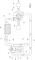
- FIG. 1 shows an example embodiment that includes an internal combustion engine (ICE) 100.
- the internal combustion engine 100 may be, for example, a compression-ignited engine, such as a diesel engine, a spark-ignited engine such as a gasoline engine, or another type of engine.
- the internal combustion engine 100 may be used in a motor vehicle (not shown), such as a passenger car, a truck or an agricultural off-road vehicle. In other embodiments, the internal combustion engine 100 may be used in power generators or power equipment.
- the internal combustion engine 100 may be used in various other applications.
- the internal combustion engine 100 may include an engine block 105 defining at least one cylinder 110.
- Each cylinder 110 may accommodate a reciprocating piston 115.
- Each piston 115 may cooperate with the cylinder 110 to define a combustion chamber 120 designed for receiving a fuel and air mixture.
- the fuel and air mixture may be ignited (typically via compression, but in some systems may be due to a heater or spark).
- the ignition of the fuel and air mixture may generate hot expanding exhaust gasses that cause the movement of the piston 115.
- the piston 115 On the opposite side of the combustion chamber 120, the piston 115 may be coupled to a crankshaft 125 in such a way that the reciprocating movements of the piston 115 are transformed in a rotational movement of the crankshaft 125.
- the internal combustion engine 100 may comprise one cylinder 110.
- the internal combustion engine 100 may comprise a plurality of cylinders 110 (e.g. 2, 3, 4, 6, or 8 cylinders), each of which may accommodate a corresponding piston 115 to define a corresponding combustion chamber 120.
- all the pistons 115 may be coupled to the same crankshaft 125.
- Each cylinder 110 may have at least two valves, including an intake valve 155 that allows air into the combustion chamber 120 and at least one exhaust valve 160 that allows exhaust gasses to exit from the combustion chamber 120.
- the valves 155 and 160 may be actuated by a camshaft (not shown) which may rotate in time with the crankshaft 125, wherein a cam phaser may be provided for selectively varying the timing between the camshaft and the crankshaft 125.
- intake air may be conveyed to the intake valve 155 by means of an air intake duct 165 that provides air from the ambient environment to the combustion chamber 120 defined by the cylinder 110.
- the intake air may be passed through an air filter prior to introduction into the combustion chamber 120.
- an intake manifold (not shown) may be provided for receiving the air from the intake duct 165 and distributing it into all the cylinders 110 via the corresponding intake valves 155.
- a throttle body 167 may be provided in the intake duct 165, for example upstream of the intake manifold if present, to regulate the flow of air into the one or more cylinders 110.
- the exhaust gasses (resulting from the ignition of the fuel and air mixture in the combustion chamber 120) may exit the engine cylinder 110 through the one or more exhaust valves 160, and may be directed into an exhaust duct 170.
- the exhaust duct 170 may convey the exhaust gasses and expel them into the ambient environment.
- all the corresponding exhaust valves 160 may be in fluid communication with an exhaust manifold (not shown), which may collect the exhaust gasses and direct them into the exhaust duct 170.
- the internal combustion engine 100 may also comprise one or more aftertreatment devices 195, which may be disposed in the exhaust duct 170 so that the exhaust gasses pass through them prior to expulsion into the ambient environment.
- the aftertreatment devices 195 may be or include any device configured to change the composition of the exhaust gasses, for example through retention and/or chemical transformation of some of their constituents.
- Some examples of aftertreatment devices 195 include, but are not limited to, catalytic converters (two and three way), oxidation catalysts, lean NO x traps, hydrocarbon adsorbers, selective catalytic reduction (SCR) systems, diesel oxidation catalysts (DOC), and particulate filters (e.g. Diesel particulate filters).
- Some embodiments may also include an exhaust gas recirculation (EGR) system for recirculating at least part of the exhaust gasses from the exhaust system back to the intake system.
- the EGR system may include an EGR duct 200 coupled between the exhaust duct 170 and the intake duct 165, for example between the exhaust manifold and the intake manifold when present.
- the EGR system may further include an EGR cooler 205 to reduce the temperature of the exhaust gasses in the EGR duct 200 and/or an EGR valve 210 for regulating a flow of exhaust gasses in the EGR duct 200.
- Other engines may not include the EGR system and the corresponding components.
- the internal combustion engine 100 may comprises a forced air system, such as a turbocharger 175.
- the turbocharger 175 may comprise a compressor 180 located in the intake duct 165 and a turbine 185 located in the exhaust duct 170 and rotationally coupled to the compressor 180.
- the turbine 185 may rotate by receiving exhaust gasses from the exhaust duct 170 that directs the exhaust gasses through a series of vanes prior to expansion through the turbine 185.
- the rotation of the turbine 185 causes the rotation of the compressor 180, whose effect is that of increasing the pressure and the temperature of the air in the intake duct 165.
- An intercooler 190 may be disposed in the intake duct 165, downstream of the compressor 180, to reduce the temperature of the air.
- the turbine 185 may be a variable geometry turbine (VGT) with a VGT actuator (not shown) arranged to move the vanes to alter the flow of the exhaust gasses through the turbine 185.
- VGT variable geometry turbine
- the turbocharger 175 may be fixed geometry and/or include a wastegate valve 500, an example of which is schematically represented in figure 6 .
- the wastegate valve 500 may be normally closed and may be opened to allow part of the exhaust gasses to bypass the turbine 185.
- the wastegate valve 500 may be actuated by an actuating device 505, which is configured to open the wastegate valve 500 when the pressure inside the intake duct 165 downstream of the compressor 180, for example inside the intake manifold (if present), exceeds a predetermined threshold value.
- the actuating device 505 may comprise a rod 510 which moves axially in response to a pressure variation in the intake duct 165 and which is connected to the wastegate valve 500 through a bolt 515.
- the rod 510 may comprise a threaded portion 520 that is screwed into a corresponding threaded hole of the bolt 515.
- the rod 510 may be blocked by means of a locking nut 525 that is screwed onto the threaded portion 520 and tightened against an axial end of the bolt 515. Once the locking nut 525 has been tightened, the locking nut 525 should never be unscrewed again, in order to prevent unintentional and/or unauthorized modifications of the rod position and thus of the behavior of wastegate valve 500.
- the fuel may be supplied into each combustion chamber 120 by an injection apparatus 130, an example of which is shown in figure 2 : the injection apparatus 130 may comprise at least one fuel injector 135, which may be coupled to the cylinder 110 or otherwise in fluid communication with the combustion chamber 120 (see figure 1 ) in order to inject fuel directly inside the combustion chamber 120.
- the injection apparatus 130 may comprise a plurality of fuel injectors 135, each of which is coupled to a corresponding cylinder 110.
- each fuel injector 135 may receive fuel from a corresponding fuel pump 600 that draws the fuel from a fuel source 605, for example a tank, and delivers it to the fuel injector 135.
- Each fuel pump 600 may be a volumetric pump, for example a piston pump.
- each fuel pump 600 may comprise a cylinder 610 and a piston (or plunger) 615 accommodated inside the cylinder 610 to define a pump chamber 620.
- the piston 615 may be actuated to slide inside the cylinder 610 between a bottom dead center position, in which the pump chamber 620 has a maximum volume, and a top dead center position, in which the pump chamber 620 has a minimum volume.
- the piston 615 may be actuated for example by a camshaft (not shown) which may rotate in time with the crankshaft 125.
- the cylinder 610 may be provided with an intake conduit 625 in communication with the fuel source 605, a delivery conduit 630 in communication with the fuel injector 135, and a return conduit 635 in communication with the fuel source 605.
- the delivery conduit 630 may be provided with a check valve 640 that only opens the delivery conduit 630 when the pressure inside the pump chamber 620 exceeds a predetermined threshold value.
- the intake conduit 625 and the return conduit 635 may be both in communication with the pump chamber 620 (as shown in figure 5 ), which is thus filled up with fuel coming from the fuel source 605.
- the piston 615 closes first the intake conduit 625 and the return conduit 635 and then compresses the fuel within the pump chamber 620, until the check valve 640 opens and allows the fuel towards the fuel injector 135.
- the lateral surface of the piston 615 may be provided with a groove 645 which is in communication with the pump chamber 620 and faces the return conduit 635, before the piston 615 reaches the top dead center position.
- the groove 645 may be oblique with respect to an axis B of the piston 615, for example it may have an helical shape, so that it faces the return conduit 635 for different axial positions of the piston 615, depending on the angular position of the piston 615 inside the cylinder 610.
- each fuel pump 600 under the same operating conditions should be able to deliver to the corresponding fuel injector 135 the same fuel quantity.
- a setting activity is usually performed at the end of the engine production line. This setting activity may generally provide for manually rotating by few degrees the cylinders 610 of the fuel pumps 600 around the corresponding axes B, while keeping the pistons 615 steady. In this way, the angular position of the groove 645 with respect to the return conduit 635 may be changed, until all the fuel pumps 600 deliver the same fuel quantity.
- each cylinder 610 may comprise a flange 650 having one or more through-holes 655.
- the flange 650 may be secured to the engine block 105, for example by means of one or more fastening screws 660, each of which passes in a corresponding through-hole 655 of the flange 650 and is screwed in a corresponding threaded hole of the engine block 105.
- the through-holes 655 of the flange 650 may be at least slightly larger than the fastening screw 660.
- the angular position of the cylinder 610 may be regulated by unscrewing at least partially the fastening screw 660, rotating the cylinder 610 around the axis B, and then screwing and tightening the fastening screw 660 again, in order to block the cylinder 610 with respect to the engine block 105.
- the cylinder 610 of each fuel pump 600 should never be moved again in order to prevent unintentional and/or unauthorized adjustments of the fuel quantity.
- the fuel quantity delivered by each fuel pump 600 may be also regulated during the operation of the internal combustion engine 100, in response to variations of the operating conditions.
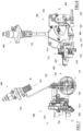
- the piston 615 may be coupled to a mechanical governor 700, as shown in figures 7-10 , which is able to rotate the piston 615 within the correspondent cylinder 610.
- the pistons 615 of all the fuel pumps 600 may be coupled to the same governor 700.
- the governor 700 may comprise a accelerator lever 705 having a predetermined rotation axis X.
- the accelerator lever 705 may be coupled to an accelerator pedal or to another accelerator element (not shown) so that, when the accelerator pedal is depressed, the accelerator lever 705 is rotated in the direction indicated with H in figure 10 .
- the governor 700 may also comprise a tensioning rocker 710 having a rotation axis Y which is parallel to the axis X.
- the tensioning rocker 710 may be connected to the accelerator lever 705 by means of a governor spring 715. In this way, when the accelerator lever 705 is rotated in the direction H, the governor spring 715 is tensioned and tends to rotate the tensioning rocker 710 in the opposite direction G.
- the tensioning rocker 710 may be rigidly coupled to a lever 720, so that the lever 720 is bound to rotate around the axis Y together with the tensioning rocker 710.
- the lever 720 may be coupled, for example by means of a spring 728, to a control rack 725 having the same rotation axis Y, so that the control rack 725 is rotationally bound to the lever 720 for rotation in direction G but is rotationally free in the opposite direction H.
- the control rack 725 may be coupled to a metering sleeve 730 of the fuel pump 600 (see figure 5 ).
- the metering sleeve 730 is rotationally bound to the piston 615 and can thus rotate, together with the piston 615, around the axis B of the latter. In this way, when the control rack 725 rotates in direction G, the metering sleeves 730 rotates the piston 615 in a direction that increases the fuel quantity delivered by the fuel pump 600.
- the governor 700 may further comprise a speed regulator 735.
- the speed regulator 735 may comprises a rotating hub 740 having a rotation axis Z which is orthogonal to the axis Y.
- the rotating hub 740 may be actuated by a camshaft (not shown) which may rotate in time with the crankshaft 125.
- the rotating hub 740 may carry flyweights that move away from the rotation axis Z in response to an increase of the rotation speed of the internal combustion engine 100 (i.e. of the crankshaft 125). This movement of the flyweights is transformed in an axial movement of a sliding bolt 745 along the axis Z that urges the lever 720 and the control rack 725 to rotate in the direction H, so as to reduce the fuel quantity delivered by the fuel pump 600.
- the governor 700 may further comprise two stop screws, including a first stop screw 800 for determining and regulating a minimum rotational speed (idle speed) of the internal combustion engine 100, and a second stop screw 805 for determining and regulating a maximum rotational speed (full load speed) of the internal combustion engine 100.
- Each one of these stop screws 800 and 805 may be screwed into a correspondent threaded through-hole of a protruding rib of a casing 750 that covers at least partially the governor 700.
- the first stop screw 800 may be disposed so that one of its ends hits the accelerator lever 705, when the latter moves in direction G to reduce the engine load.
- the second stop screw 805 may be disposed so that one of its ends hits the accelerator lever 705, when the latter moves in direction H to increase the engine load.
- the first and the second stop screws 800 and 805 define and limit the rotation of the accelerator lever 705, thereby defining the minimum and the maximum quantity of fuel that can be supplied to the injector(s) 135 of the internal combustion engine 100.
- These minimum and/or maximum quantities may be adjusted by screwing or unscrewing the stop screws 800 and 805 in the correspondent though-holes of the casing 750, thereby varying their axial position. This regulation may be performed by authorized personnel at the end of the engine production line and, after that, the stop screws 800 and 805 may be blocked by a locking nut 815. Once the locking nuts 815 have been tightened, they should never be manipulated again, in order to prevent unintentional and/or unauthorized adjustments of the stop screws 800 and 805.
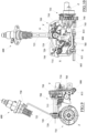
- the governor 700 comprises a torque control device 900, as shown for example in figure 8 and 11 .
- the torque control device 900 comprise: a cylindrical housing 905 having a threaded external surface.
- the cylindrical housing 905 may be screwed into a threaded through-hole of the casing 750, so that a first end of the cylindrical housing 905 is exposed on the external side of the casing and the second end protrudes inside.
- the cylindrical housing 905 accommodates a pin 910 having an head 915 that protrudes from the second end of the cylindrical housing 905 towards the interior of the casing 750.
- the pin 910 can slide inside the cylindrical housing 905 from an extracted position (shown in figure 11 ), in which the head 915 is located at a maximum distance from the second end of the cylindrical housing 905, and a retracted position (not shown), wherein the head 915 is located at a minimum distance from the second end of the cylindrical housing 905 (e.g. in contact).
- the stroke of the pin 910 between these two positions may be quite small and may be limited, on one side, by the head 915 and, on the opposite side, by a nut 920 that is screwed onto a threaded portion of the pin 910 that protrudes from the first end of the cylindrical housing 905 .
- a spring 925 may be accommodated inside the cylindrical housing 905 to push the pin 910 towards the extracted position.
- the torque control device 900 may be disposed so that the sliding axis of the pin 910 is orthogonal to the rotation axis Y of the tensioning rocker 710 and so that the head 915 hits the tensioning rocker 710, when the latter moves in direction G to increase the engine load. In this way, the axial movement of the pin 910, in response to the rotation of the tensioning rocker 710, allows at least a partial control of the torque generated by the internal combustion engine 100.
- This effect may be adjusted by screwing or unscrewing the cylindrical housing 905 of the torque control device 900 with respect to the casing 750 and/or by screwing or unscrewing the nut 920, thereby varying the axial position of the head 915.
- These regulations may be performed by authorized personnel at the end of the engine production line. After these regulations have been performed, the cylindrical housing 905 and the nut 920 should not be manipulated again, in order to prevent unintentional and/or unauthorized modifications of the behavior of the torque control device 900.
- an anti-tampering device 400 is used.
- the anti-tampering device 400 comprises a threaded element 405 that may be embodied as a nut.
- the threaded element 405 may have a first base 410 and a second base 415, which may be for example planar and parallel to one another, and a through-hole 420 extending between these first and second bases.
- a female (internal) thread 425 may be realized on the internal surface of the through-hole 420.
- the thread 425 defines a screwing axis A of the threaded element 405 and is dimensioned to engage the male (external) thread of the cylindrical housing 905, thereby allowing the threaded element 405 to be coaxially screwed onto the cylindrical housing 905 and be tightened against the casing 750, to block the cylindrical housing 905 in the desired position.
- the latter comprises an engaging surface 430 for engagement with a driving tool, for example a wrench.
- the engaging surface 430 may be an external surface of the threaded element 405, for example an external surface that surrounds at least partially the through-hole 420.
- the engaging surface 430 may be a prismatic surface whose generators are parallel to the screwing axis A defined by the thread 425.
- the cross-section of the engaging surface 430 may have any shape, for example triangular, rectangular, square, pentagonal, hexagonal, heptagonal, octagonal, polygonal, star-shaped or any other shape having at least a linear segment and which is suitable to realize a prismatic joint between the threaded element 405 and a driving tool.
- the engaging surface 430 may be located in proximity of the first base 410 of the threaded element 405 which is destined to come into contact with the casing 750.
- the cylindrical housing 905 may protrude from the second base 415, in order to make the nut 920 accessible from the outside.
- the anti-tampering device 400 further comprises a protection body 435 designed to be coupled to the threaded element 405 for preventing the engaging surface 430 from being engaged by the driving tool.
- the protection body 435 comprises an annular wall 440, for example having a cylindrical shape, which coaxially surrounds the threaded element 405, thereby covering the engaging surface 430.
- the annular wall 440 has a first axial end 445, which is open for insertion of the threaded element 405, and an opposite second axial end 450.
- the first axial end 445 may be substantially coplanar with the first base 410 of the threaded element 405.
- the second axial end 450 may protrude over the second base 415 and may be closed by a back wall 455, so that the protection body 435 assumes the shape of a cap that covers and encloses the threaded element 405 and also the protruding portion of the cylindrical housing 905, including for example the nut 920.
- the back wall 455 may have any possible shape, for example a planar shape or dome shape.
- the protection body 435 is coupled to the threaded element 405 so that the protection body 435 is axially blocked to the threaded element 405 but free to spin around the screwing axis A.
- This coupling is achieved by means of a retaining ring 460 which is partly accommodated in an annular groove 465 of the threaded element 405 and partly accommodated in an annular groove 470 of the protection body 435.
- the retaining ring 460 and the annular grooves 465 and 470 are all coaxial to the screwing axis A.
- the annular groove 465 is realized on the external surface of the threaded element 405, for example in a cylindrical portion thereof that is located in proximity of the second base 415.
- the annular groove 470 is realized on the internal surface of the annular wall 440 of the protection body 435.
- the axial distance between the annular groove 470 and the first axial end 445 of the protection body 435 may be equal or almost equal to the distance between the annular groove 465 and the first base 410 of the threaded element 405.
- an elastomeric ring 475 for example an annular gasket, is coaxially interposed and radially compressed between the external surface of the cylindrical housing 905 and the annular wall 440 of the protection body 435.
- the retaining ring 460 may be coupled to the annular groove 465 of the threaded element 405, before the coupling of the protection body 435.
- the internal surface of the annular wall 440 may comprise an annular portion 480 that is tapered towards the annular groove 465. In this way, during the axial insertion of protection body 435 onto the threaded element 405, the tapered portion 480 radially compresses the retaining ring 460, which may deform elastically.
- the retaining ring 460 elastically snaps into the annular groove 470, thereby realizing a form fitting that blocks the protection body 435 to the threaded element 405 in axial direction but allow it to freely spin around the screwing axis A.
- the protection body 435 since the protection body 435 spins around the screwing axis A, the protection body 435 cannot transmit torque to the threaded element 405, thereby ensuring that the threaded element 405 cannot be screwed or unscrewed in any way.
- the axial engagement between the protection body 435 and the two annular grooves 465 and 470 ensures that the protection body 435 cannot be removed, so that the threaded element 405 and the nut 920 can never be screwed or unscrewed again.
- the retaining ring 460 may have a rectangular cross section.
- the cross section of the retaining ring 460 made with a plane containing the screwing axis A, may have a rectangular shape.
- the planar surfaces of the retaining ring 460 acting of the planar surfaces of the annular grooves 465 and 470, make an axial removal of the protection body 435 extremely difficult if not impossible.
- An anti-tampering device of this kind is not only dedicated to the torque control device 900 but can be also applied to any threaded element that, once screwed in a desired position, for example at the end of the engine production line, should not be manipulated unintentionally and/or by unauthorized users, in order to not modify the performance of the internal combustion engine 100 or for any other reasons.
- the anti-tampering device 400 may comprise a threaded element 405 which is embodied as a screw and which may be used for example to replace the fastening screw 660 of the fuel pumps 600.
- This threaded element 405 may particularly comprise a head 485, a shank 490 coaxially protruding from the head 485 and a male (external) thread 425 realized on the external surface of the shank 490.
- the thread 425 defines the screwing axis A of the threaded element 405 and may be dimensioned to pass through a corresponding hole 655 of the flange 650 and to engage a corresponding threaded hole the engine block 105.
- the head 485 may comprise an engaging surface 430 for engagement with a driving tool, for example a wrench or a screwdriver.
- the head 485 may comprise a cavity or socket 495, which is realized on the opposite side with respect to the shank 490 (e.g. centered on the screwing axis A), and the engaging surface 430 may be an internal surface delimiting said cavity 495.
- the engaging surface 430 could be an external surface of the head 485. Either way, the engaging surface 430 may be a prismatic surface whose generators are parallel to the screwing axis A.
- the cross-section of the engaging surface 430, with a plane orthogonal to the screwing axis A, may have any shape, for example triangular, rectangular, square, pentagonal, hexagonal, heptagonal, octagonal, polygonal, star-shaped or any other shape having at least a linear segment which is suitable to realize a prismatic joint between the head 675 and a driving tool.
- the protection body 435 may comprise an annular wall 440, for example having a cylindrical shape, which coaxially surrounds the head 485.
- the annular wall 440 may have a first axial end 445, which is open for insertion of the head 485, and an opposite second axial end 450, which is closed by a back wall 455, so as to cover completely or at least partially the mouth of the cavity 495.
- the protection body 435 may be coupled to the threaded element 405 as explained above, for example by means of a retaining ring 460, having for example a rectangular cross-section, which is partly accommodated in an annular groove 465 of the threaded element 405 and partly accommodated in an annular groove 470 of the protection body 435, wherein the annular groove 465 may be realized on the external surface of the threaded element 405, for example in a cylindrical portion thereof, and the annular groove 470 may be realized on the internal surface of the annular wall 440. Also in this example, between the first axial end 445 and the annular groove 465, the internal surface of the annular wall 440 may comprise an annular portion 480 that is tapered towards the annular groove 465.
- the anti-tampering device 400 may comprise a threaded element 405 which is again embodied as a nut.
- the threaded element 405 may be used, for example, to replace the locking nut 525 of the wastegate valve 500, as indicated in figure 13 , but it could also be used to replace the locking nut 815 of the first and second stop screws 800 and 805.
- the threaded element 405 of this third example has essentially the same features described in connection with the first example above.
- the protection body 435 can be coupled to the threaded element 405 to prevents his unintentional and/or unauthorized manipulation.
- the protection body 435, and its coupling to the threaded element 405, may have the same features described for the first example above, with the only difference that the second axial end 450 of the annular wall 440 may be open.
Landscapes
- Engineering & Computer Science (AREA)
- General Engineering & Computer Science (AREA)
- Mechanical Engineering (AREA)
- Chemical & Material Sciences (AREA)
- Combustion & Propulsion (AREA)
- Fuel-Injection Apparatus (AREA)
- Burglar Alarm Systems (AREA)
Description
- The present disclosure relates to an anti-tampering device particularly, but not exclusively, for use in an internal combustion engine.
- Some internal combustion engines, such as some internal combustion engines having mechanical injection systems, may be equipped with one or more threaded elements (e.g. screws or nuts) that may control some of the operating parameters of the engine. These threaded elements may, in some systems, be screwed or unscrewed using conventional driving tools (e.g. wrenches or screwdrivers), in order to adjust some of the operating parameters of the internal combustion engine, such as for example the fuel injected quantity.
- The adjustment of these engine operating parameters may be carried out at various times, such as at the end of the production line by authorized personnel of the engine manufacturer in order to guarantee a proper functioning of the internal combustion engine and a limited level of polluting emissions. However, in some systems where the above-mentioned threaded elements are exposed on the external side of the internal combustion engine, they could be exposed to the environment or tampered with (e.g. screwed or unscrewed without permission) by unauthorized people. For example, after the internal combustion engine has been sold, unauthorized people may tamper with the screw controlling the fuel injection, thereby affecting the performance and potentially altering the engine to produce polluting emissions , without the approval and the consent of the engine manufacturer. The document
JP H07 49069 A - An object of the present disclosure is that of solving, or at least positively reducing, the above mentioned drawback with a simple, rational, secure and rather inexpensive solution.
- This and other objects are achieved by the embodiments of the disclosure having the features included in the independent claim.
- The dependent claims delineate additional aspects of the various embodiments.
- An embodiment of the present invention provides an anti-tampering device with the features of claim 1.
- Thanks to this solution, the first threaded element of the anti-tampering device can be assembled in an internal combustion engine to allow the adjustment of an engine parameter. Once the engine parameter has been properly adjusted, the protection body can be coupled to the first threaded element, thereby preventing the engagement of the first threaded element with a corresponding driving tool (e.g. with a corresponding wrench or screwdriver). Since the protection body is axially blocked with respect to the first threaded element, the protection body cannot be removed to free the engaging surface of the first threaded element. On the other hand, since the protection body spins freely with respect to first threaded element around the screwing axis, the protection body is completely unable to transmit torque to the first threaded element and thus it cannot be used to actively rotate the first threaded element. In this way, once the protection body has been coupled, the first threaded element cannot be actively rotated (e.g. screwed or unscrewed) and the engine operating parameter cannot be adjusted.
- According to an aspect of the anti-tampering device, the engaging surface of the first threaded element may be a prismatic surface whose generators are parallel to the screwing axis.
- This aspect allows to realize a prismatic joint between the first threaded element and the driving tool, which prevents mutual rotations and thus facilitate screwing and unscrewing of the first threaded element. The cross-section of the engaging surface with a plane orthogonal to the screwing axis may have any shape, for example triangular, rectangular, square, pentagonal, hexagonal, heptagonal, octagonal, polygonal, star-shaped or any other shape having at least a linear segment.
- According to some embodiments, the engaging surface may be an external surface of the first threaded element and the protection body may comprise an annular wall surrounding the engaging surface.
- Other embodiments may provide that the engaging surface is an internal surface delimiting a cavity (or socket) of the first threaded element and that the protection body comprises a back wall that covers at least partially a mouth of the cavity.
- Thanks to both these solutions, the protection body is effectively able to prevent the engagement of the first threaded element with the corresponding driving tools.
- According to an aspect of the anti-tampering device, the protection body is coupled to the first threaded element by means of a retaining ring partly accommodated in an annular groove of the first threaded element and partly accommodated in an annular groove of the protection body.
- This solution renders the coupling between the first threaded element the protection body quite simple and reliable.
- In an embodiment of the present disclosure, the protection body's annular groove is realized on an internal surface of an annular wall of the protection body which surrounds at least partially the first threaded element and which has at least an open end for coupling with the first threaded element.
- Thank to this solution, the protection body can be easily inserted onto the first threaded organ after the first threaded organ has been screwed or unscrewed using the driving tool.
- According to some embodiments, an opposite end of the annular wall may be closed by a back wall of the protection body.
- In this way the protection body is embodied as a sort of cap that encloses and covers the first threaded element not only on its lateral sides but also on one axial side.
- The back wall of the protection body may have any possible shape, for example a planar shape or dome shape.
- Other embodiments may however provide that the opposite end of the annular wall is open so that the protection body becomes as a sort of ring that only covers the lateral sides of the first threaded organ. According to an aspect of the anti-tampering device, the internal surface of the annular wall may comprise, between the open end and the annular groove, an annular portion tapered towards the annular groove.
- This tapered annular portion has the effect of radially compressing the retaining ring during the axial insertion of the protection body onto the threaded organ and until it snaps into the annular groove, thereby facilitating the coupling between the first threaded element and the protection body. According to another aspect of the anti-tampering device, the retaining ring has a rectangular cross-section (with respect to a plane containing the screwing axis).
- In this way, once the retaining ring has been accommodated in the annular grooves of the first threaded element and of the protection body, the retaining ring cannot be removed anymore, thereby preventing the protection body from being separated from the first threaded element.
- The thread of the first threaded element is a female (internal) thread.
- By way of example, the first threaded element may be embodied as a nut having central hole (e.g. a blind hole or a passing hole) which is internally threaded, and an external surface (e.g. a polygonal surface) which defines the engaging surface.
- The anti-tampering device further comprises a second threaded element having a male thread that is screwed into the female thread of the first threaded element.
- In this way, the second threaded element can be effectively used to adjust the engine operating parameter whereas the first threaded element may be used to block to second threaded element in a desired position.
- According to a further aspect of this embodiment, an elastomeric ring is coaxially interposed between the second threaded element and the annular wall of the protection body.
- This annular gasket has the effect of reducing the noise that can be originated by the vibrations of the protection body on the threaded element.
- The present invention will now be described, by way of example, with reference to the accompanying drawings.
-
Fig.1 is a schematic view an embodiment of an internal combustion engine which incorporates the features of the disclosure; -
Fig.2 shows an injection apparatus of the internal combustion engine; -
Fig.3 shows a detail of the injection apparatus; -
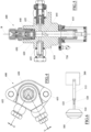
Fig.4 is a top view of a fuel pump of the injection apparatus; -
Fig.5 is the section V-V offigure 4 ; -
Fig.6 is a schematic view of a wastegate valve of the internal combustion engine; -
Fig. 7-10 are views of a mechanical governor for the fuel pump; -
Fig.11 is a cross-section of an anti-tampering device according to an embodiment of the invention; -
Fig. 12 is a cross-section of an anti-tampering device according to a second embodiment not in the scope of the invention; -
Fig. 13 is a cross-section of an anti-tampering device according to a third embodiment not in the scope of the invention. -
FIG. 1 shows an example embodiment that includes an internal combustion engine (ICE) 100. Theinternal combustion engine 100 may be, for example, a compression-ignited engine, such as a diesel engine, a spark-ignited engine such as a gasoline engine, or another type of engine. Theinternal combustion engine 100 may be used in a motor vehicle (not shown), such as a passenger car, a truck or an agricultural off-road vehicle. In other embodiments, theinternal combustion engine 100 may be used in power generators or power equipment. Theinternal combustion engine 100 may be used in various other applications. - The
internal combustion engine 100 may include anengine block 105 defining at least onecylinder 110. Eachcylinder 110 may accommodate a reciprocatingpiston 115. Eachpiston 115 may cooperate with thecylinder 110 to define acombustion chamber 120 designed for receiving a fuel and air mixture. The fuel and air mixture may be ignited (typically via compression, but in some systems may be due to a heater or spark). The ignition of the fuel and air mixture may generate hot expanding exhaust gasses that cause the movement of thepiston 115. On the opposite side of thecombustion chamber 120, thepiston 115 may be coupled to acrankshaft 125 in such a way that the reciprocating movements of thepiston 115 are transformed in a rotational movement of thecrankshaft 125. - The
internal combustion engine 100 may comprise onecylinder 110. In other systems, theinternal combustion engine 100 may comprise a plurality of cylinders 110 (e.g. 2, 3, 4, 6, or 8 cylinders), each of which may accommodate acorresponding piston 115 to define acorresponding combustion chamber 120. In multiple-cylinder engines, all thepistons 115 may be coupled to thesame crankshaft 125. Eachcylinder 110 may have at least two valves, including anintake valve 155 that allows air into thecombustion chamber 120 and at least oneexhaust valve 160 that allows exhaust gasses to exit from thecombustion chamber 120. Thevalves crankshaft 125, wherein a cam phaser may be provided for selectively varying the timing between the camshaft and thecrankshaft 125. - intake air may be conveyed to the
intake valve 155 by means of anair intake duct 165 that provides air from the ambient environment to thecombustion chamber 120 defined by thecylinder 110. The intake air may be passed through an air filter prior to introduction into thecombustion chamber 120. If theinternal combustion engine 100 comprises a plurality ofcylinders 110, an intake manifold (not shown) may be provided for receiving the air from theintake duct 165 and distributing it into all thecylinders 110 via the correspondingintake valves 155. In some embodiments, athrottle body 167 may be provided in theintake duct 165, for example upstream of the intake manifold if present, to regulate the flow of air into the one ormore cylinders 110. - The exhaust gasses (resulting from the ignition of the fuel and air mixture in the combustion chamber 120) may exit the
engine cylinder 110 through the one ormore exhaust valves 160, and may be directed into anexhaust duct 170. Theexhaust duct 170 may convey the exhaust gasses and expel them into the ambient environment. In some embodiments where theinternal combustion engine 100 comprises a plurality ofcylinders 110, all thecorresponding exhaust valves 160 may be in fluid communication with an exhaust manifold (not shown), which may collect the exhaust gasses and direct them into theexhaust duct 170. - The
internal combustion engine 100 may also comprise one or moreaftertreatment devices 195, which may be disposed in theexhaust duct 170 so that the exhaust gasses pass through them prior to expulsion into the ambient environment. Theaftertreatment devices 195 may be or include any device configured to change the composition of the exhaust gasses, for example through retention and/or chemical transformation of some of their constituents. Some examples ofaftertreatment devices 195 include, but are not limited to, catalytic converters (two and three way), oxidation catalysts, lean NOx traps, hydrocarbon adsorbers, selective catalytic reduction (SCR) systems, diesel oxidation catalysts (DOC), and particulate filters (e.g. Diesel particulate filters). - Some embodiments may also include an exhaust gas recirculation (EGR) system for recirculating at least part of the exhaust gasses from the exhaust system back to the intake system. The EGR system may include an
EGR duct 200 coupled between theexhaust duct 170 and theintake duct 165, for example between the exhaust manifold and the intake manifold when present. The EGR system may further include an EGR cooler 205 to reduce the temperature of the exhaust gasses in theEGR duct 200 and/or anEGR valve 210 for regulating a flow of exhaust gasses in theEGR duct 200. Other engines may not include the EGR system and the corresponding components. In some embodiments, theinternal combustion engine 100 may comprises a forced air system, such as aturbocharger 175. Other internal combustion engines may not include theturbocharger 175 and the corresponding components for turbocharging. The turbocharger 175 (if present) may comprise acompressor 180 located in theintake duct 165 and aturbine 185 located in theexhaust duct 170 and rotationally coupled to thecompressor 180. Theturbine 185 may rotate by receiving exhaust gasses from theexhaust duct 170 that directs the exhaust gasses through a series of vanes prior to expansion through theturbine 185. The rotation of theturbine 185 causes the rotation of thecompressor 180, whose effect is that of increasing the pressure and the temperature of the air in theintake duct 165. Anintercooler 190 may be disposed in theintake duct 165, downstream of thecompressor 180, to reduce the temperature of the air. In some examples, theturbine 185 may be a variable geometry turbine (VGT) with a VGT actuator (not shown) arranged to move the vanes to alter the flow of the exhaust gasses through theturbine 185. In other embodiments, theturbocharger 175 may be fixed geometry and/or include a wastegate valve 500, an example of which is schematically represented infigure 6 . - The wastegate valve 500 may be normally closed and may be opened to allow part of the exhaust gasses to bypass the
turbine 185. The wastegate valve 500 may be actuated by anactuating device 505, which is configured to open the wastegate valve 500 when the pressure inside theintake duct 165 downstream of thecompressor 180, for example inside the intake manifold (if present), exceeds a predetermined threshold value. Theactuating device 505 may comprise arod 510 which moves axially in response to a pressure variation in theintake duct 165 and which is connected to the wastegate valve 500 through abolt 515. In particular, therod 510 may comprise a threadedportion 520 that is screwed into a corresponding threaded hole of thebolt 515. In this way, by screwing or unscrewing the threadedportion 520 with respect to thebolt 515, it is possible to change the effective length of therod 510, thereby adjusting the pressure threshold value at which the wastegate valve 500 opens. After this regulation, which can be performed by authorized personnel at the end of the engine production line, therod 510 may be blocked by means of a lockingnut 525 that is screwed onto the threadedportion 520 and tightened against an axial end of thebolt 515. Once the lockingnut 525 has been tightened, the lockingnut 525 should never be unscrewed again, in order to prevent unintentional and/or unauthorized modifications of the rod position and thus of the behavior of wastegate valve 500. The fuel may be supplied into eachcombustion chamber 120 by aninjection apparatus 130, an example of which is shown infigure 2 : theinjection apparatus 130 may comprise at least onefuel injector 135, which may be coupled to thecylinder 110 or otherwise in fluid communication with the combustion chamber 120 (seefigure 1 ) in order to inject fuel directly inside thecombustion chamber 120. In multiple-cylinder engines, theinjection apparatus 130 may comprise a plurality offuel injectors 135, each of which is coupled to acorresponding cylinder 110. - In some embodiments, each
fuel injector 135 may receive fuel from a correspondingfuel pump 600 that draws the fuel from afuel source 605, for example a tank, and delivers it to thefuel injector 135. Eachfuel pump 600 may be a volumetric pump, for example a piston pump. As shown in the example offigure 5 , eachfuel pump 600 may comprise acylinder 610 and a piston (or plunger) 615 accommodated inside thecylinder 610 to define apump chamber 620. Thepiston 615 may be actuated to slide inside thecylinder 610 between a bottom dead center position, in which thepump chamber 620 has a maximum volume, and a top dead center position, in which thepump chamber 620 has a minimum volume. Thepiston 615 may be actuated for example by a camshaft (not shown) which may rotate in time with thecrankshaft 125. Thecylinder 610 may be provided with anintake conduit 625 in communication with thefuel source 605, adelivery conduit 630 in communication with thefuel injector 135, and areturn conduit 635 in communication with thefuel source 605. Thedelivery conduit 630 may be provided with acheck valve 640 that only opens thedelivery conduit 630 when the pressure inside thepump chamber 620 exceeds a predetermined threshold value. When thepiston 615 is in the bottom dead center position, theintake conduit 625 and thereturn conduit 635 may be both in communication with the pump chamber 620 (as shown infigure 5 ), which is thus filled up with fuel coming from thefuel source 605. During the motion towards the top dead center position, thepiston 615 closes first theintake conduit 625 and thereturn conduit 635 and then compresses the fuel within thepump chamber 620, until thecheck valve 640 opens and allows the fuel towards thefuel injector 135. - To regulate the fuel quantity supplied to the
fuel injector 135, the lateral surface of thepiston 615 may be provided with agroove 645 which is in communication with thepump chamber 620 and faces thereturn conduit 635, before thepiston 615 reaches the top dead center position. In this way, the last part of the fuel that has been trapped inside thepump chamber 620 is not delivered to thefuel injector 135 but, flowing through thegroove 645, is returned to thefuel source 605. Thegroove 645 may be oblique with respect to an axis B of thepiston 615, for example it may have an helical shape, so that it faces thereturn conduit 635 for different axial positions of thepiston 615, depending on the angular position of thepiston 615 inside thecylinder 610. As a consequence, by changing the angular position of thepiston 615 inside thecylinder 610 is effectively possible to regulate the quantity of fuel that is returned to thefuel source 605 and thus the fuel quantity that is delivered to thefuel injector 135. - In multiple-cylinder engines, each
fuel pump 600 under the same operating conditions should be able to deliver to the correspondingfuel injector 135 the same fuel quantity. Since the fuel pumps 600 may be slightly different from one another, for example due to production spread, a setting activity is usually performed at the end of the engine production line. This setting activity may generally provide for manually rotating by few degrees thecylinders 610 of the fuel pumps 600 around the corresponding axes B, while keeping thepistons 615 steady. In this way, the angular position of thegroove 645 with respect to thereturn conduit 635 may be changed, until all the fuel pumps 600 deliver the same fuel quantity. To allow this regulation, eachcylinder 610 may comprise aflange 650 having one or more through-holes 655. As shown infigure 3 , theflange 650 may be secured to theengine block 105, for example by means of one or more fastening screws 660, each of which passes in a corresponding through-hole 655 of theflange 650 and is screwed in a corresponding threaded hole of theengine block 105. In particular, the through-holes 655 of theflange 650 may be at least slightly larger than thefastening screw 660. In this way, the angular position of thecylinder 610 may be regulated by unscrewing at least partially thefastening screw 660, rotating thecylinder 610 around the axis B, and then screwing and tightening thefastening screw 660 again, in order to block thecylinder 610 with respect to theengine block 105. Once the right angular position has been reached, thecylinder 610 of eachfuel pump 600 should never be moved again in order to prevent unintentional and/or unauthorized adjustments of the fuel quantity. Irrespective of the preliminary setting detailed above, the fuel quantity delivered by eachfuel pump 600 may be also regulated during the operation of theinternal combustion engine 100, in response to variations of the operating conditions. To allow this regulation, thepiston 615 may be coupled to amechanical governor 700, as shown infigures 7-10 , which is able to rotate thepiston 615 within thecorrespondent cylinder 610. In multiple-cylinder engines, thepistons 615 of all the fuel pumps 600 may be coupled to thesame governor 700. - The
governor 700 may comprise aaccelerator lever 705 having a predetermined rotation axis X. Theaccelerator lever 705 may be coupled to an accelerator pedal or to another accelerator element (not shown) so that, when the accelerator pedal is depressed, theaccelerator lever 705 is rotated in the direction indicated with H infigure 10 . Thegovernor 700 may also comprise atensioning rocker 710 having a rotation axis Y which is parallel to the axis X. Thetensioning rocker 710 may be connected to theaccelerator lever 705 by means of agovernor spring 715. In this way, when theaccelerator lever 705 is rotated in the direction H, thegovernor spring 715 is tensioned and tends to rotate thetensioning rocker 710 in the opposite direction G. Thetensioning rocker 710 may be rigidly coupled to alever 720, so that thelever 720 is bound to rotate around the axis Y together with thetensioning rocker 710. Thelever 720 may be coupled, for example by means of aspring 728, to acontrol rack 725 having the same rotation axis Y, so that thecontrol rack 725 is rotationally bound to thelever 720 for rotation in direction G but is rotationally free in the opposite direction H. Thecontrol rack 725 may be coupled to ametering sleeve 730 of the fuel pump 600 (seefigure 5 ). Themetering sleeve 730 is rotationally bound to thepiston 615 and can thus rotate, together with thepiston 615, around the axis B of the latter. In this way, when thecontrol rack 725 rotates in direction G, themetering sleeves 730 rotates thepiston 615 in a direction that increases the fuel quantity delivered by thefuel pump 600. - The
governor 700 may further comprise aspeed regulator 735. Thespeed regulator 735 may comprises arotating hub 740 having a rotation axis Z which is orthogonal to the axis Y. Therotating hub 740 may be actuated by a camshaft (not shown) which may rotate in time with thecrankshaft 125. Therotating hub 740 may carry flyweights that move away from the rotation axis Z in response to an increase of the rotation speed of the internal combustion engine 100 (i.e. of the crankshaft 125). This movement of the flyweights is transformed in an axial movement of a slidingbolt 745 along the axis Z that urges thelever 720 and thecontrol rack 725 to rotate in the direction H, so as to reduce the fuel quantity delivered by thefuel pump 600. - The
governor 700 may further comprise two stop screws, including afirst stop screw 800 for determining and regulating a minimum rotational speed (idle speed) of theinternal combustion engine 100, and asecond stop screw 805 for determining and regulating a maximum rotational speed (full load speed) of theinternal combustion engine 100. Each one of these stop screws 800 and 805 may be screwed into a correspondent threaded through-hole of a protruding rib of acasing 750 that covers at least partially thegovernor 700. In particular, thefirst stop screw 800 may be disposed so that one of its ends hits theaccelerator lever 705, when the latter moves in direction G to reduce the engine load. On the other hand, thesecond stop screw 805 may be disposed so that one of its ends hits theaccelerator lever 705, when the latter moves in direction H to increase the engine load. In this way, the first and the second stop screws 800 and 805 define and limit the rotation of theaccelerator lever 705, thereby defining the minimum and the maximum quantity of fuel that can be supplied to the injector(s) 135 of theinternal combustion engine 100. These minimum and/or maximum quantities may be adjusted by screwing or unscrewing the stop screws 800 and 805 in the correspondent though-holes of thecasing 750, thereby varying their axial position. This regulation may be performed by authorized personnel at the end of the engine production line and, after that, the stop screws 800 and 805 may be blocked by a lockingnut 815. Once the lockingnuts 815 have been tightened, they should never be manipulated again, in order to prevent unintentional and/or unauthorized adjustments of the stop screws 800 and 805. - The
governor 700 comprises atorque control device 900, as shown for example infigure 8 and11 . Thetorque control device 900 comprise: acylindrical housing 905 having a threaded external surface. Thecylindrical housing 905 may be screwed into a threaded through-hole of thecasing 750, so that a first end of thecylindrical housing 905 is exposed on the external side of the casing and the second end protrudes inside. Thecylindrical housing 905 accommodates apin 910 having anhead 915 that protrudes from the second end of thecylindrical housing 905 towards the interior of thecasing 750. Thepin 910 can slide inside thecylindrical housing 905 from an extracted position (shown infigure 11 ), in which thehead 915 is located at a maximum distance from the second end of thecylindrical housing 905, and a retracted position (not shown), wherein thehead 915 is located at a minimum distance from the second end of the cylindrical housing 905 (e.g. in contact). The stroke of thepin 910 between these two positions may be quite small and may be limited, on one side, by thehead 915 and, on the opposite side, by anut 920 that is screwed onto a threaded portion of thepin 910 that protrudes from the first end of thecylindrical housing 905 . Aspring 925 may be accommodated inside thecylindrical housing 905 to push thepin 910 towards the extracted position. Thetorque control device 900 may be disposed so that the sliding axis of thepin 910 is orthogonal to the rotation axis Y of thetensioning rocker 710 and so that thehead 915 hits thetensioning rocker 710, when the latter moves in direction G to increase the engine load. In this way, the axial movement of thepin 910, in response to the rotation of thetensioning rocker 710, allows at least a partial control of the torque generated by theinternal combustion engine 100. - This effect may be adjusted by screwing or unscrewing the
cylindrical housing 905 of thetorque control device 900 with respect to thecasing 750 and/or by screwing or unscrewing thenut 920, thereby varying the axial position of thehead 915. These regulations may be performed by authorized personnel at the end of the engine production line. After these regulations have been performed, thecylindrical housing 905 and thenut 920 should not be manipulated again, in order to prevent unintentional and/or unauthorized modifications of the behavior of thetorque control device 900. - In order to prevent this unintentional and/or unauthorized manipulation, an
anti-tampering device 400 is used. Theanti-tampering device 400 comprises a threadedelement 405 that may be embodied as a nut. In particular, the threadedelement 405 may have afirst base 410 and asecond base 415, which may be for example planar and parallel to one another, and a through-hole 420 extending between these first and second bases. A female (internal)thread 425 may be realized on the internal surface of the through-hole 420. Thethread 425 defines a screwing axis A of the threadedelement 405 and is dimensioned to engage the male (external) thread of thecylindrical housing 905, thereby allowing the threadedelement 405 to be coaxially screwed onto thecylindrical housing 905 and be tightened against thecasing 750, to block thecylindrical housing 905 in the desired position. - To facilitate the screwing of the threaded
element 405, the latter comprises anengaging surface 430 for engagement with a driving tool, for example a wrench. In this example, the engagingsurface 430 may be an external surface of the threadedelement 405, for example an external surface that surrounds at least partially the through-hole 420. Theengaging surface 430 may be a prismatic surface whose generators are parallel to the screwing axis A defined by thethread 425. The cross-section of theengaging surface 430, performed with a plane orthogonal to the screwing axis A, may have any shape, for example triangular, rectangular, square, pentagonal, hexagonal, heptagonal, octagonal, polygonal, star-shaped or any other shape having at least a linear segment and which is suitable to realize a prismatic joint between the threadedelement 405 and a driving tool. Theengaging surface 430 may be located in proximity of thefirst base 410 of the threadedelement 405 which is destined to come into contact with thecasing 750. On the other side, thecylindrical housing 905 may protrude from thesecond base 415, in order to make thenut 920 accessible from the outside. - The
anti-tampering device 400 further comprises aprotection body 435 designed to be coupled to the threadedelement 405 for preventing theengaging surface 430 from being engaged by the driving tool. In this example, theprotection body 435 comprises anannular wall 440, for example having a cylindrical shape, which coaxially surrounds the threadedelement 405, thereby covering theengaging surface 430. Theannular wall 440 has a firstaxial end 445, which is open for insertion of the threadedelement 405, and an opposite secondaxial end 450. The firstaxial end 445 may be substantially coplanar with thefirst base 410 of the threadedelement 405. The secondaxial end 450 may protrude over thesecond base 415 and may be closed by aback wall 455, so that theprotection body 435 assumes the shape of a cap that covers and encloses the threadedelement 405 and also the protruding portion of thecylindrical housing 905, including for example thenut 920. Theback wall 455 may have any possible shape, for example a planar shape or dome shape. - The
protection body 435 is coupled to the threadedelement 405 so that theprotection body 435 is axially blocked to the threadedelement 405 but free to spin around the screwing axis A. This coupling is achieved by means of a retainingring 460 which is partly accommodated in anannular groove 465 of the threadedelement 405 and partly accommodated in anannular groove 470 of theprotection body 435. The retainingring 460 and theannular grooves annular groove 465 is realized on the external surface of the threadedelement 405, for example in a cylindrical portion thereof that is located in proximity of thesecond base 415. Theannular groove 470 is realized on the internal surface of theannular wall 440 of theprotection body 435. The axial distance between theannular groove 470 and the firstaxial end 445 of theprotection body 435 may be equal or almost equal to the distance between theannular groove 465 and thefirst base 410 of the threadedelement 405. In order to reduce the noise that can be originated by vibrations of theprotection body 435 on the threadedelement 405, anelastomeric ring 475, for example an annular gasket, is coaxially interposed and radially compressed between the external surface of thecylindrical housing 905 and theannular wall 440 of theprotection body 435. - For the
anti-tempering device 400 to be assembled, the retainingring 460 may be coupled to theannular groove 465 of the threadedelement 405, before the coupling of theprotection body 435. Between the firstaxial end 445 and theannular groove 465, the internal surface of theannular wall 440 may comprise anannular portion 480 that is tapered towards theannular groove 465. In this way, during the axial insertion ofprotection body 435 onto the threadedelement 405, the taperedportion 480 radially compresses the retainingring 460, which may deform elastically. When theannular groove 470 faces theannular groove 465, the retainingring 460 elastically snaps into theannular groove 470, thereby realizing a form fitting that blocks theprotection body 435 to the threadedelement 405 in axial direction but allow it to freely spin around the screwing axis A. Once theprotection body 435 has been coupled this way, the nut 20 and the threadedelement 405, particularly its engagingsurface 430, become inaccessible form the outside and cannot be screwed or unscrewed either manually or with the driving tools. In addition, since theprotection body 435 spins around the screwing axis A, theprotection body 435 cannot transmit torque to the threadedelement 405, thereby ensuring that the threadedelement 405 cannot be screwed or unscrewed in any way. On the other hand, the axial engagement between theprotection body 435 and the twoannular grooves protection body 435 cannot be removed, so that the threadedelement 405 and thenut 920 can never be screwed or unscrewed again. - In order to improve the strength and the security of the axial binding between the
protection body 435 and the threadedelement 405, the retainingring 460 may have a rectangular cross section. In other words, the cross section of the retainingring 460, made with a plane containing the screwing axis A, may have a rectangular shape. In this way, the planar surfaces of the retainingring 460, acting of the planar surfaces of theannular grooves protection body 435 extremely difficult if not impossible. - An anti-tampering device of this kind is not only dedicated to the
torque control device 900 but can be also applied to any threaded element that, once screwed in a desired position, for example at the end of the engine production line, should not be manipulated unintentionally and/or by unauthorized users, in order to not modify the performance of theinternal combustion engine 100 or for any other reasons. - By way of example, a similar
anti-tempering device 400 is shown infigure 12 , where the components of theanti-tampering device 400 in common with the first example above are indicated with the same reference numbers. In this case, theanti-tampering device 400 may comprise a threadedelement 405 which is embodied as a screw and which may be used for example to replace thefastening screw 660 of the fuel pumps 600. This threadedelement 405 may particularly comprise ahead 485, ashank 490 coaxially protruding from thehead 485 and a male (external)thread 425 realized on the external surface of theshank 490. Thethread 425 defines the screwing axis A of the threadedelement 405 and may be dimensioned to pass through acorresponding hole 655 of theflange 650 and to engage a corresponding threaded hole theengine block 105. To facilitate the screwing and the unscrewing of the threadedelement 405, thehead 485 may comprise anengaging surface 430 for engagement with a driving tool, for example a wrench or a screwdriver. In this example, thehead 485 may comprise a cavity orsocket 495, which is realized on the opposite side with respect to the shank 490 (e.g. centered on the screwing axis A), and theengaging surface 430 may be an internal surface delimiting saidcavity 495. However, in other embodiments, the engagingsurface 430 could be an external surface of thehead 485. Either way, the engagingsurface 430 may be a prismatic surface whose generators are parallel to the screwing axis A. The cross-section of theengaging surface 430, with a plane orthogonal to the screwing axis A, may have any shape, for example triangular, rectangular, square, pentagonal, hexagonal, heptagonal, octagonal, polygonal, star-shaped or any other shape having at least a linear segment which is suitable to realize a prismatic joint between the head 675 and a driving tool. - For preventing the threaded
element 405 from being manipulated, theprotection body 435 may comprise anannular wall 440, for example having a cylindrical shape, which coaxially surrounds thehead 485. Theannular wall 440 may have a firstaxial end 445, which is open for insertion of thehead 485, and an opposite secondaxial end 450, which is closed by aback wall 455, so as to cover completely or at least partially the mouth of thecavity 495. Theprotection body 435 may be coupled to the threadedelement 405 as explained above, for example by means of a retainingring 460, having for example a rectangular cross-section, which is partly accommodated in anannular groove 465 of the threadedelement 405 and partly accommodated in anannular groove 470 of theprotection body 435, wherein theannular groove 465 may be realized on the external surface of the threadedelement 405, for example in a cylindrical portion thereof, and theannular groove 470 may be realized on the internal surface of theannular wall 440. Also in this example, between the firstaxial end 445 and theannular groove 465, the internal surface of theannular wall 440 may comprise anannular portion 480 that is tapered towards theannular groove 465. - Another similar
anti-tampering device 400 is shown infigure 13 , wherein the components of the anti-tampering device in common with the first example above are indicated with the same reference numbers. In this case, theanti-tampering device 400 may comprise a threadedelement 405 which is again embodied as a nut. The threadedelement 405 may be used, for example, to replace the lockingnut 525 of the wastegate valve 500, as indicated infigure 13 , but it could also be used to replace the lockingnut 815 of the first and second stop screws 800 and 805. The threadedelement 405 of this third example has essentially the same features described in connection with the first example above. Once the threadedelement 405 have been tightened, theprotection body 435 can be coupled to the threadedelement 405 to prevents his unintentional and/or unauthorized manipulation. Theprotection body 435, and its coupling to the threadedelement 405, may have the same features described for the first example above, with the only difference that the secondaxial end 450 of theannular wall 440 may be open. - While at least one exemplary embodiment has been presented in the foregoing summary and detailed description, it should be appreciated that a vast number of variations exist. It should also be appreciated that the exemplary embodiment or exemplary embodiments are only examples, and are not intended to limit the scope, applicability, or configuration in any way. Rather, the foregoing summary and detailed description will provide those skilled in the art with a convenient road map for implementing at least one exemplary embodiment, it being understood that various changes may be made in the function and arrangement of elements described in an exemplary embodiment without departing from the scope as set forth in the appended claims.
Claims (9)
- An anti-tampering device (400) comprising- a first threaded element (405) having a female thread (425) defining a screwing axis (A) and an engaging surface (430) for engagement with a driving tool,- a second threaded element (905) having a male thread that is screwed into the female thread of the first threaded element (405), and- a protection body (435) for preventing the driving tool from engaging the engaging surface (430),wherein the protection body (435) is coupled to the first threaded element (405) so that they are mutually blocked in a direction parallel to the screwing axis (A) and free to spin around the screwing axis (A),wherein the protection body (435) is coupled to the first threaded element (405) by means of a retaining ring (460) partly accommodated in an annular groove (465) of the first threaded element (405) and partly accommodated in an annular groove (470) of the protection body (435),wherein the protection body's annular groove (470) is realized on an internal surface of an annular wall (440) of the protection body (435) which surrounds at least partially the first threaded element (405) and which has at least an open end for coupling with the first threaded element (405),characterized for comprising an elastomeric ring (475) coaxially interposed between the second threaded element (905) and the annular wall (440) of the protection body (435).
- An anti-tampering device (400) according to claim 1, wherein the engaging surface (430) of the first threaded element (405) is a prismatic surface whose generators are parallel to the screwing axis (A).
- An anti-tempering device (400) according to claim 1 or 2, wherein the engaging surface (430) is an external surface of the first threaded element (405) and the annular wall (440) surrounds the engaging surface (430).
- An anti-tampering device (400) according to claim 1 or 2, wherein the engaging surface (430) is an internal surface delimiting a cavity (495) of the first threaded element (405) and the protection body (435) comprises a back wall (455) that covers at least partially a mouth of the cavity (495).
- An anti-tampering device (400) according to any of the preceding claims, wherein an opposite end (450) of the annular wall (440) is closed by a back wall (455) of the protection body (435).
- An anti-tampering device (400) according to any of the preceding claims, wherein an opposite end (450) of the annular wall (440) is open.
- An anti-tampering device (400) according to any of the preceding claims, wherein the internal surface of the annular wall (440) comprises, between the open end (445) and the annular groove (470), an annular portion (480) tapered towards the annular groove (470).
- An anti-tampering device (400) according to any of the preceding claims, wherein the retaining ring (460) has a rectangular cross-section.
- A torque control device (900) comprising:- a cylindrical housing (905) having a threaded external surface, the cylindrical housing (905) being screwed into a threaded through-hole of a casing (750), so that a first end of the cylindrical housing (905) is exposed on the external side of the casing and the second end protrudes inside;- a pin (910) having an head (915) that protrudes from the second end of the cylindrical housing (905) towards the interior of the casing (750), the pin (910) being slidable inside the cylindrical housing (905) from an extracted position, in which the head (915) is located at a maximum distance from the second end of the cylindrical housing (905), and a retracted position, wherein the head (915) is located at a minimum distance from the second end of the cylindrical housing (905);- a spring (925) accommodated inside the cylindrical housing (905) to push the pin (910) towards the extracted position, and- an anti-tampering device (400) according to claim 1, wherein the second threaded element is the cylindrical housing (905).
Applications Claiming Priority (1)
| Application Number | Priority Date | Filing Date | Title |
|---|---|---|---|
| IT102018000006324A IT201800006324A1 (en) | 2018-06-14 | 2018-06-14 | ANTI-TAMPERING DEVICE |
Publications (2)
| Publication Number | Publication Date |
|---|---|
| EP3581814A1 EP3581814A1 (en) | 2019-12-18 |
| EP3581814B1 true EP3581814B1 (en) | 2023-10-04 |
Family
ID=63449608
Family Applications (1)
| Application Number | Title | Priority Date | Filing Date |
|---|---|---|---|
| EP19173829.3A Active EP3581814B1 (en) | 2018-06-14 | 2019-05-10 | An anti-tampering device |
Country Status (4)
| Country | Link |
|---|---|
| US (1) | US11060553B2 (en) |
| EP (1) | EP3581814B1 (en) |
| CN (1) | CN110608090B (en) |
| IT (1) | IT201800006324A1 (en) |
Family Cites Families (14)
| Publication number | Priority date | Publication date | Assignee | Title |
|---|---|---|---|---|
| DE1509099A1 (en) * | 1962-12-18 | 1969-07-31 | Artur Fischer | Fastening element for corrugated roof panels |
| DE2825486C2 (en) * | 1978-06-08 | 1980-03-13 | Horst Guenter 1000 Berlin Rissmann | Screw fastening for motor vehicle wheels |
| US4400123A (en) * | 1980-07-14 | 1983-08-23 | Rodun Development Corporation | Nut and thread protector |
| DE3217371C2 (en) * | 1981-07-25 | 1983-12-22 | Ing. Walter Hengst GmbH & Co KG, 4400 Münster | Loosening safety device for one screw |
| US4736603A (en) * | 1982-07-22 | 1988-04-12 | Donald Brushaber | Marine drive unit anti-theft device |
| GB8402197D0 (en) * | 1984-01-27 | 1984-02-29 | Hirst J A B | Cover |
| US5071300A (en) * | 1991-02-15 | 1991-12-10 | Mcgard, Inc. | Shrouded jam locknut |
| JPH0749069Y2 (en) * | 1992-02-26 | 1995-11-13 | 株式会社精工舎 | Magnetically levitated bearing device for rotating shaft |
| JP2838754B2 (en) * | 1993-06-04 | 1998-12-16 | 株式会社クボタ | Engine adjustment bolt sealing device |
| DE202013011657U1 (en) * | 2013-01-23 | 2014-03-12 | Erwin Hirt | Anti-theft nut or anti-theft screw lockable with key lock or combination lock |
| US20150226249A1 (en) * | 2014-02-07 | 2015-08-13 | Barnes Group Inc. | Torque Retention Arrangement |
| JP6466828B2 (en) | 2015-12-25 | 2019-02-06 | 株式会社クボタ | Equipment with adjustment bolt |
| EP3260712B1 (en) * | 2016-06-24 | 2021-04-07 | Kubota Corporation | Device with adjustment bolt |
| CN206458711U (en) | 2017-01-23 | 2017-09-01 | 河南旭德隆机械有限公司 | The antitheft protection against anti-tampering device of bolt is used for a long time in field |
-
2018
- 2018-06-14 IT IT102018000006324A patent/IT201800006324A1/en unknown
-
2019
- 2019-05-10 EP EP19173829.3A patent/EP3581814B1/en active Active
- 2019-06-10 US US16/435,905 patent/US11060553B2/en active Active
- 2019-06-13 CN CN201910509558.5A patent/CN110608090B/en active Active
Also Published As
| Publication number | Publication date |
|---|---|
| US11060553B2 (en) | 2021-07-13 |
| CN110608090B (en) | 2022-05-03 |
| US20190383321A1 (en) | 2019-12-19 |
| EP3581814A1 (en) | 2019-12-18 |
| IT201800006324A1 (en) | 2019-12-14 |
| CN110608090A (en) | 2019-12-24 |
Similar Documents
| Publication | Publication Date | Title |
|---|---|---|
| US7163005B2 (en) | Cooler bypass valve system and method | |
| AU740045B2 (en) | Internal combustion engine fuel management system | |
| US9714617B2 (en) | System and method for limiting a volumetric efficiency of an engine during engine cranking to reduce emission | |
| US10677175B2 (en) | Ventilation controls for dual-fuel engines | |
| Bromberg et al. | Optimized PFI+ DI operation for minimizing DI gasoline engine particulates | |
| EP3581814B1 (en) | An anti-tampering device | |
| US10428767B2 (en) | Low pressure natural gas direct injection fuel injector assembly | |
| US20090165761A1 (en) | Fuel control system having a cold start strategy | |
| RU2699856C2 (en) | Combustion system for engine (embodiments) and cylinder block head for use in this system | |
| US20150260061A1 (en) | Fluid pump assembly for an internal combustion engine | |
| US6910269B2 (en) | Method of converting diesel engine to natural gas engine | |
| US8011094B2 (en) | Method of converting diesel engine to natural gas engine | |
| GB2533610A (en) | Fuel unit pump and internal combustion engine comprising it | |
| USRE46889E1 (en) | Method of converting diesel engine to natural gas engine | |
| DE102011113925A1 (en) | Method for controlling combustion engine e.g. direct-injection petrol engine, involves setting time appropriate for opening exhaust and inlet valves, when detected temperature of refrigerant is below threshold value | |
| FR3044360B1 (en) | SYSTEM AND METHOD FOR DEACTIVATING AT LEAST ONE CYLINDER OF AN ENGINE, INTAKE COLLECTOR AND HEAT EXCHANGER COMPRISING SAID SYSTEM | |
| US10247333B2 (en) | Self opening clamp | |
| WO2025133879A1 (en) | Internal combustion engine powered by gaseous fuels | |
| DE102021204501A1 (en) | Operation of an internal combustion engine depending on water in the exhaust system | |
| Mao et al. | Study of idle speed control strategies of GD-1 high pressure common rail diesel engine. | |
| Kawano et al. | Effects of indirect water injection in turbocharged internal combustion engines with spark ignition and direct fuel injection | |
| Waleed et al. | ALLAH DOES NOT BURDEN A SOUL BEYOND THAT IT CAN BEAR | |
| WO2004011787A1 (en) | Internal combustion engine |
Legal Events
| Date | Code | Title | Description |
|---|---|---|---|
| PUAI | Public reference made under article 153(3) epc to a published international application that has entered the european phase |
Free format text: ORIGINAL CODE: 0009012 |
|
| STAA | Information on the status of an ep patent application or granted ep patent |
Free format text: STATUS: THE APPLICATION HAS BEEN PUBLISHED |
|
| AK | Designated contracting states |
Kind code of ref document: A1 Designated state(s): AL AT BE BG CH CY CZ DE DK EE ES FI FR GB GR HR HU IE IS IT LI LT LU LV MC MK MT NL NO PL PT RO RS SE SI SK SM TR |
|
| AX | Request for extension of the european patent |
Extension state: BA ME |
|
| STAA | Information on the status of an ep patent application or granted ep patent |
Free format text: STATUS: REQUEST FOR EXAMINATION WAS MADE |
|
| 17P | Request for examination filed |
Effective date: 20200327 |
|
| RBV | Designated contracting states (corrected) |
Designated state(s): AL AT BE BG CH CY CZ DE DK EE ES FI FR GB GR HR HU IE IS IT LI LT LU LV MC MK MT NL NO PL PT RO RS SE SI SK SM TR |
|
| STAA | Information on the status of an ep patent application or granted ep patent |
Free format text: STATUS: EXAMINATION IS IN PROGRESS |
|
| 17Q | First examination report despatched |
Effective date: 20210831 |
|
| GRAP | Despatch of communication of intention to grant a patent |
Free format text: ORIGINAL CODE: EPIDOSNIGR1 |
|
| STAA | Information on the status of an ep patent application or granted ep patent |
Free format text: STATUS: GRANT OF PATENT IS INTENDED |
|
| RIC1 | Information provided on ipc code assigned before grant |
Ipc: F16B 43/00 20060101ALN20230502BHEP Ipc: F16B 21/18 20060101ALN20230502BHEP Ipc: F16B 41/00 20060101ALI20230502BHEP Ipc: F16B 37/14 20060101AFI20230502BHEP |
|
| INTG | Intention to grant announced |
Effective date: 20230517 |
|
| GRAS | Grant fee paid |
Free format text: ORIGINAL CODE: EPIDOSNIGR3 |
|
| GRAA | (expected) grant |
Free format text: ORIGINAL CODE: 0009210 |
|
| STAA | Information on the status of an ep patent application or granted ep patent |
Free format text: STATUS: THE PATENT HAS BEEN GRANTED |
|
| P01 | Opt-out of the competence of the unified patent court (upc) registered |
Effective date: 20230817 |
|
| AK | Designated contracting states |
Kind code of ref document: B1 Designated state(s): AL AT BE BG CH CY CZ DE DK EE ES FI FR GB GR HR HU IE IS IT LI LT LU LV MC MK MT NL NO PL PT RO RS SE SI SK SM TR |
|
| REG | Reference to a national code |
Ref country code: GB Ref legal event code: FG4D |
|
| REG | Reference to a national code |
Ref country code: CH Ref legal event code: EP |
|
| REG | Reference to a national code |
Ref country code: IE Ref legal event code: FG4D |
|
| REG | Reference to a national code |
Ref country code: DE Ref legal event code: R096 Ref document number: 602019038494 Country of ref document: DE |
|
| REG | Reference to a national code |
Ref country code: LT Ref legal event code: MG9D |
|
| REG | Reference to a national code |
Ref country code: NL Ref legal event code: MP Effective date: 20231004 |
|
| REG | Reference to a national code |
Ref country code: AT Ref legal event code: MK05 Ref document number: 1618028 Country of ref document: AT Kind code of ref document: T Effective date: 20231004 |
|
| PG25 | Lapsed in a contracting state [announced via postgrant information from national office to epo] |
Ref country code: NL Free format text: LAPSE BECAUSE OF FAILURE TO SUBMIT A TRANSLATION OF THE DESCRIPTION OR TO PAY THE FEE WITHIN THE PRESCRIBED TIME-LIMIT Effective date: 20231004 |
|
| PG25 | Lapsed in a contracting state [announced via postgrant information from national office to epo] |
Ref country code: GR Free format text: LAPSE BECAUSE OF FAILURE TO SUBMIT A TRANSLATION OF THE DESCRIPTION OR TO PAY THE FEE WITHIN THE PRESCRIBED TIME-LIMIT Effective date: 20240105 |
|
| PG25 | Lapsed in a contracting state [announced via postgrant information from national office to epo] |
Ref country code: IS Free format text: LAPSE BECAUSE OF FAILURE TO SUBMIT A TRANSLATION OF THE DESCRIPTION OR TO PAY THE FEE WITHIN THE PRESCRIBED TIME-LIMIT Effective date: 20240204 |
|
| PG25 | Lapsed in a contracting state [announced via postgrant information from national office to epo] |
Ref country code: LT Free format text: LAPSE BECAUSE OF FAILURE TO SUBMIT A TRANSLATION OF THE DESCRIPTION OR TO PAY THE FEE WITHIN THE PRESCRIBED TIME-LIMIT Effective date: 20231004 |
|
| PG25 | Lapsed in a contracting state [announced via postgrant information from national office to epo] |
Ref country code: AT Free format text: LAPSE BECAUSE OF FAILURE TO SUBMIT A TRANSLATION OF THE DESCRIPTION OR TO PAY THE FEE WITHIN THE PRESCRIBED TIME-LIMIT Effective date: 20231004 |
|
| PG25 | Lapsed in a contracting state [announced via postgrant information from national office to epo] |
Ref country code: ES Free format text: LAPSE BECAUSE OF FAILURE TO SUBMIT A TRANSLATION OF THE DESCRIPTION OR TO PAY THE FEE WITHIN THE PRESCRIBED TIME-LIMIT Effective date: 20231004 |
|
| PG25 | Lapsed in a contracting state [announced via postgrant information from national office to epo] |
Ref country code: LT Free format text: LAPSE BECAUSE OF FAILURE TO SUBMIT A TRANSLATION OF THE DESCRIPTION OR TO PAY THE FEE WITHIN THE PRESCRIBED TIME-LIMIT Effective date: 20231004 Ref country code: IS Free format text: LAPSE BECAUSE OF FAILURE TO SUBMIT A TRANSLATION OF THE DESCRIPTION OR TO PAY THE FEE WITHIN THE PRESCRIBED TIME-LIMIT Effective date: 20240204 Ref country code: GR Free format text: LAPSE BECAUSE OF FAILURE TO SUBMIT A TRANSLATION OF THE DESCRIPTION OR TO PAY THE FEE WITHIN THE PRESCRIBED TIME-LIMIT Effective date: 20240105 Ref country code: ES Free format text: LAPSE BECAUSE OF FAILURE TO SUBMIT A TRANSLATION OF THE DESCRIPTION OR TO PAY THE FEE WITHIN THE PRESCRIBED TIME-LIMIT Effective date: 20231004 Ref country code: BG Free format text: LAPSE BECAUSE OF FAILURE TO SUBMIT A TRANSLATION OF THE DESCRIPTION OR TO PAY THE FEE WITHIN THE PRESCRIBED TIME-LIMIT Effective date: 20240104 Ref country code: AT Free format text: LAPSE BECAUSE OF FAILURE TO SUBMIT A TRANSLATION OF THE DESCRIPTION OR TO PAY THE FEE WITHIN THE PRESCRIBED TIME-LIMIT Effective date: 20231004 Ref country code: PT Free format text: LAPSE BECAUSE OF FAILURE TO SUBMIT A TRANSLATION OF THE DESCRIPTION OR TO PAY THE FEE WITHIN THE PRESCRIBED TIME-LIMIT Effective date: 20240205 |
|
| PG25 | Lapsed in a contracting state [announced via postgrant information from national office to epo] |
Ref country code: SE Free format text: LAPSE BECAUSE OF FAILURE TO SUBMIT A TRANSLATION OF THE DESCRIPTION OR TO PAY THE FEE WITHIN THE PRESCRIBED TIME-LIMIT Effective date: 20231004 Ref country code: RS Free format text: LAPSE BECAUSE OF FAILURE TO SUBMIT A TRANSLATION OF THE DESCRIPTION OR TO PAY THE FEE WITHIN THE PRESCRIBED TIME-LIMIT Effective date: 20231004 Ref country code: PL Free format text: LAPSE BECAUSE OF FAILURE TO SUBMIT A TRANSLATION OF THE DESCRIPTION OR TO PAY THE FEE WITHIN THE PRESCRIBED TIME-LIMIT Effective date: 20231004 Ref country code: NO Free format text: LAPSE BECAUSE OF FAILURE TO SUBMIT A TRANSLATION OF THE DESCRIPTION OR TO PAY THE FEE WITHIN THE PRESCRIBED TIME-LIMIT Effective date: 20240104 Ref country code: LV Free format text: LAPSE BECAUSE OF FAILURE TO SUBMIT A TRANSLATION OF THE DESCRIPTION OR TO PAY THE FEE WITHIN THE PRESCRIBED TIME-LIMIT Effective date: 20231004 Ref country code: HR Free format text: LAPSE BECAUSE OF FAILURE TO SUBMIT A TRANSLATION OF THE DESCRIPTION OR TO PAY THE FEE WITHIN THE PRESCRIBED TIME-LIMIT Effective date: 20231004 |
|
| REG | Reference to a national code |
Ref country code: DE Ref legal event code: R097 Ref document number: 602019038494 Country of ref document: DE |
|
| PG25 | Lapsed in a contracting state [announced via postgrant information from national office to epo] |
Ref country code: DK Free format text: LAPSE BECAUSE OF FAILURE TO SUBMIT A TRANSLATION OF THE DESCRIPTION OR TO PAY THE FEE WITHIN THE PRESCRIBED TIME-LIMIT Effective date: 20231004 |
|
| PG25 | Lapsed in a contracting state [announced via postgrant information from national office to epo] |
Ref country code: CZ Free format text: LAPSE BECAUSE OF FAILURE TO SUBMIT A TRANSLATION OF THE DESCRIPTION OR TO PAY THE FEE WITHIN THE PRESCRIBED TIME-LIMIT Effective date: 20231004 |
|
| PG25 | Lapsed in a contracting state [announced via postgrant information from national office to epo] |
Ref country code: SK Free format text: LAPSE BECAUSE OF FAILURE TO SUBMIT A TRANSLATION OF THE DESCRIPTION OR TO PAY THE FEE WITHIN THE PRESCRIBED TIME-LIMIT Effective date: 20231004 |
|
| PG25 | Lapsed in a contracting state [announced via postgrant information from national office to epo] |
Ref country code: SM Free format text: LAPSE BECAUSE OF FAILURE TO SUBMIT A TRANSLATION OF THE DESCRIPTION OR TO PAY THE FEE WITHIN THE PRESCRIBED TIME-LIMIT Effective date: 20231004 Ref country code: SK Free format text: LAPSE BECAUSE OF FAILURE TO SUBMIT A TRANSLATION OF THE DESCRIPTION OR TO PAY THE FEE WITHIN THE PRESCRIBED TIME-LIMIT Effective date: 20231004 Ref country code: RO Free format text: LAPSE BECAUSE OF FAILURE TO SUBMIT A TRANSLATION OF THE DESCRIPTION OR TO PAY THE FEE WITHIN THE PRESCRIBED TIME-LIMIT Effective date: 20231004 Ref country code: EE Free format text: LAPSE BECAUSE OF FAILURE TO SUBMIT A TRANSLATION OF THE DESCRIPTION OR TO PAY THE FEE WITHIN THE PRESCRIBED TIME-LIMIT Effective date: 20231004 Ref country code: DK Free format text: LAPSE BECAUSE OF FAILURE TO SUBMIT A TRANSLATION OF THE DESCRIPTION OR TO PAY THE FEE WITHIN THE PRESCRIBED TIME-LIMIT Effective date: 20231004 Ref country code: CZ Free format text: LAPSE BECAUSE OF FAILURE TO SUBMIT A TRANSLATION OF THE DESCRIPTION OR TO PAY THE FEE WITHIN THE PRESCRIBED TIME-LIMIT Effective date: 20231004 |
|
| PLBE | No opposition filed within time limit |
Free format text: ORIGINAL CODE: 0009261 |
|
| STAA | Information on the status of an ep patent application or granted ep patent |
Free format text: STATUS: NO OPPOSITION FILED WITHIN TIME LIMIT |
|
| 26N | No opposition filed |
Effective date: 20240705 |
|
| PG25 | Lapsed in a contracting state [announced via postgrant information from national office to epo] |
Ref country code: SI Free format text: LAPSE BECAUSE OF FAILURE TO SUBMIT A TRANSLATION OF THE DESCRIPTION OR TO PAY THE FEE WITHIN THE PRESCRIBED TIME-LIMIT Effective date: 20231004 |
|
| PG25 | Lapsed in a contracting state [announced via postgrant information from national office to epo] |
Ref country code: SI Free format text: LAPSE BECAUSE OF FAILURE TO SUBMIT A TRANSLATION OF THE DESCRIPTION OR TO PAY THE FEE WITHIN THE PRESCRIBED TIME-LIMIT Effective date: 20231004 |
|
| REG | Reference to a national code |
Ref country code: CH Ref legal event code: PL |
|
| PG25 | Lapsed in a contracting state [announced via postgrant information from national office to epo] |
Ref country code: MC Free format text: LAPSE BECAUSE OF FAILURE TO SUBMIT A TRANSLATION OF THE DESCRIPTION OR TO PAY THE FEE WITHIN THE PRESCRIBED TIME-LIMIT Effective date: 20231004 |
|
| PG25 | Lapsed in a contracting state [announced via postgrant information from national office to epo] |
Ref country code: LU Free format text: LAPSE BECAUSE OF NON-PAYMENT OF DUE FEES Effective date: 20240510 |
|
| PG25 | Lapsed in a contracting state [announced via postgrant information from national office to epo] |
Ref country code: MC Free format text: LAPSE BECAUSE OF FAILURE TO SUBMIT A TRANSLATION OF THE DESCRIPTION OR TO PAY THE FEE WITHIN THE PRESCRIBED TIME-LIMIT Effective date: 20231004 Ref country code: LU Free format text: LAPSE BECAUSE OF NON-PAYMENT OF DUE FEES Effective date: 20240510 Ref country code: CH Free format text: LAPSE BECAUSE OF NON-PAYMENT OF DUE FEES Effective date: 20240531 |
|
| REG | Reference to a national code |
Ref country code: BE Ref legal event code: MM Effective date: 20240531 |
|
| PG25 | Lapsed in a contracting state [announced via postgrant information from national office to epo] |
Ref country code: IE Free format text: LAPSE BECAUSE OF NON-PAYMENT OF DUE FEES Effective date: 20240510 |
|
| PG25 | Lapsed in a contracting state [announced via postgrant information from national office to epo] |
Ref country code: BE Free format text: LAPSE BECAUSE OF NON-PAYMENT OF DUE FEES Effective date: 20240531 |
|
| PGFP | Annual fee paid to national office [announced via postgrant information from national office to epo] |
Ref country code: DE Payment date: 20250529 Year of fee payment: 7 |
|
| PGFP | Annual fee paid to national office [announced via postgrant information from national office to epo] |
Ref country code: IT Payment date: 20250326 Year of fee payment: 7 |
|
| PGFP | Annual fee paid to national office [announced via postgrant information from national office to epo] |
Ref country code: FR Payment date: 20250526 Year of fee payment: 7 |
|
| PG25 | Lapsed in a contracting state [announced via postgrant information from national office to epo] |
Ref country code: CY Free format text: LAPSE BECAUSE OF FAILURE TO SUBMIT A TRANSLATION OF THE DESCRIPTION OR TO PAY THE FEE WITHIN THE PRESCRIBED TIME-LIMIT; INVALID AB INITIO Effective date: 20190510 |
|
| PG25 | Lapsed in a contracting state [announced via postgrant information from national office to epo] |
Ref country code: HU Free format text: LAPSE BECAUSE OF FAILURE TO SUBMIT A TRANSLATION OF THE DESCRIPTION OR TO PAY THE FEE WITHIN THE PRESCRIBED TIME-LIMIT; INVALID AB INITIO Effective date: 20190510 |
|
| PG25 | Lapsed in a contracting state [announced via postgrant information from national office to epo] |
Ref country code: FI Free format text: LAPSE BECAUSE OF FAILURE TO SUBMIT A TRANSLATION OF THE DESCRIPTION OR TO PAY THE FEE WITHIN THE PRESCRIBED TIME-LIMIT Effective date: 20231004 |
|
| PGFP | Annual fee paid to national office [announced via postgrant information from national office to epo] |
Ref country code: GB Payment date: 20260303 Year of fee payment: 8 |