EP3581495A1 - Synchronous locking pin assembly - Google Patents
Synchronous locking pin assembly Download PDFInfo
- Publication number
- EP3581495A1 EP3581495A1 EP19179704.2A EP19179704A EP3581495A1 EP 3581495 A1 EP3581495 A1 EP 3581495A1 EP 19179704 A EP19179704 A EP 19179704A EP 3581495 A1 EP3581495 A1 EP 3581495A1
- Authority
- EP
- European Patent Office
- Prior art keywords
- shaft
- synchronizer
- groove
- axis
- sidewall
- Prior art date
- Legal status (The legal status is an assumption and is not a legal conclusion. Google has not performed a legal analysis and makes no representation as to the accuracy of the status listed.)
- Granted
Links
Images


Classifications
-
- B—PERFORMING OPERATIONS; TRANSPORTING
- B64—AIRCRAFT; AVIATION; COSMONAUTICS
- B64D—EQUIPMENT FOR FITTING IN OR TO AIRCRAFT; FLIGHT SUITS; PARACHUTES; ARRANGEMENT OR MOUNTING OF POWER PLANTS OR PROPULSION TRANSMISSIONS IN AIRCRAFT
- B64D9/00—Equipment for handling freight; Equipment for facilitating passenger embarkation or the like
- B64D9/003—Devices for retaining pallets or freight containers
-
- B—PERFORMING OPERATIONS; TRANSPORTING
- B60—VEHICLES IN GENERAL
- B60P—VEHICLES ADAPTED FOR LOAD TRANSPORTATION OR TO TRANSPORT, TO CARRY, OR TO COMPRISE SPECIAL LOADS OR OBJECTS
- B60P7/00—Securing or covering of load on vehicles
- B60P7/06—Securing of load
- B60P7/13—Securing freight containers or forwarding containers on vehicles
-
- B—PERFORMING OPERATIONS; TRANSPORTING
- B63—SHIPS OR OTHER WATERBORNE VESSELS; RELATED EQUIPMENT
- B63B—SHIPS OR OTHER WATERBORNE VESSELS; EQUIPMENT FOR SHIPPING
- B63B25/00—Load-accommodating arrangements, e.g. stowing, trimming; Vessels characterised thereby
- B63B25/002—Load-accommodating arrangements, e.g. stowing, trimming; Vessels characterised thereby for goods other than bulk goods
-
- F—MECHANICAL ENGINEERING; LIGHTING; HEATING; WEAPONS; BLASTING
- F16—ENGINEERING ELEMENTS AND UNITS; GENERAL MEASURES FOR PRODUCING AND MAINTAINING EFFECTIVE FUNCTIONING OF MACHINES OR INSTALLATIONS; THERMAL INSULATION IN GENERAL
- F16B—DEVICES FOR FASTENING OR SECURING CONSTRUCTIONAL ELEMENTS OR MACHINE PARTS TOGETHER, e.g. NAILS, BOLTS, CIRCLIPS, CLAMPS, CLIPS OR WEDGES; JOINTS OR JOINTING
- F16B21/00—Means for preventing relative axial movement of a pin, spigot, shaft or the like and a member surrounding it; Stud-and-socket releasable fastenings
- F16B21/02—Releasable fastening devices locking by rotation
-
- F—MECHANICAL ENGINEERING; LIGHTING; HEATING; WEAPONS; BLASTING
- F16—ENGINEERING ELEMENTS AND UNITS; GENERAL MEASURES FOR PRODUCING AND MAINTAINING EFFECTIVE FUNCTIONING OF MACHINES OR INSTALLATIONS; THERMAL INSULATION IN GENERAL
- F16B—DEVICES FOR FASTENING OR SECURING CONSTRUCTIONAL ELEMENTS OR MACHINE PARTS TOGETHER, e.g. NAILS, BOLTS, CIRCLIPS, CLAMPS, CLIPS OR WEDGES; JOINTS OR JOINTING
- F16B19/00—Bolts without screw-thread; Pins, including deformable elements; Rivets
- F16B19/02—Bolts or sleeves for positioning of machine parts, e.g. notched taper pins, fitting pins, sleeves, eccentric positioning rings
Definitions
- Exemplary embodiments pertain to the art of cargo loading systems.
- the shaft 40 extends between a first shaft end 60 and a second shaft end 62 along the first axis 32. Referring to FIG. 4 , the shaft 40 defines a first shaft groove 64 that is disposed proximate the first shaft end 60 and a second shaft groove 66 that is disposed proximate the second shaft end 62.
- the shaft 40 defines a shaft opening 80 that extends from an exterior surface of the shaft 40 towards the first axis 32 along a second axis 82.
- the shaft opening 80 is disposed between the first shaft groove 64 and the second shaft groove 66.
- the shaft 40 defines a complementary anti-rotation feature or a flat 86 that is disposed proximate the first shaft end 60, as shown in FIGS. 1 and 5 .
- the flat 86 of the shaft 40 is arranged to engage the anti-rotation feature 26 to inhibit rotation of the shaft 40 about the first axis 32.
- the first retention pin 42 is slidably and rotatably received within the shaft 40.
- the first retention pin 42 extends at least partially through the first shaft end 60.
- the first retention pin 42 is arranged to move along the first axis 32 relative to the first shaft end 60 or the first sidewall 20, in response to rotation of the synchronizer 46 about the first axis 32 to move the locking pin assembly 30 between the locked position and the unlocked position.
- the first retention pin 42 extends between a first retention pin first end 90 and a first retention pin second end 92 along the first axis 32.
- the first retention pin second end 92 extends into the shaft 40.
- the first retention pin 42 defines a first pin opening 94 that is disposed proximate the first retention pin second end 92.
- the first pin opening 94 is proximately aligned with the first shaft groove 64.
- the synchronizer 46 is disposed about the shaft 40, the first retention pin 42, and the second retention pin 44.
- the synchronizer 46 is rotatable about the first axis 32 relative to the shaft 40.
- the synchronizer 46 is rotatable between a first position that corresponds to the locked position of the locking pin assembly 30 and a second position that corresponds to the unlocked position of the locking pin assembly 30.
- the synchronizer 46 extends between a first synchronizer end 110 and a second synchronizer end 112 along the first axis 32.
- the synchronizer 46 defines a first synchronizer groove 114 that is disposed proximate the first synchronizer end 110 and a second synchronizer groove 116 that is disposed proximate the second synchronizer end 112.
- the first synchronizer groove 114 is partially aligned with or crosses over the first shaft groove 64.
- the second synchronizer groove 116 is partially aligned or crosses over with the second shaft groove 66.
- the first synchronizer groove 114 may be spaced apart from the second synchronizer groove 116.
- the first synchronizer groove 114 and the second synchronizer groove 116 are arranged as guide openings that extend from an exterior surface of the synchronizer 46 towards the shaft 40 and the first axis 32.
- the first synchronizer groove 114 and the second synchronizer groove 116 are disposed in a non-parallel and non-perpendicular relationship with respect to the first axis 32, with respect to the each and with respect to the first shaft groove 64 and the second shaft groove 66.
- the first synchronizer groove 114 is angled in an opposite direction as the first shaft groove 64 and the second synchronizer groove 116 is angled in an opposite direction as the second shaft groove 66.
- the first synchronizer groove 114 and the second synchronizer groove 116 include a first synchronizer groove end 120, a second synchronizer groove end 122, and synchronizer groove walls 124 that extend between the first synchronizer groove end 120 and the second synchronizer groove end 122.
- the synchronizer 46 includes a first tab or first extension 130 that extends from the first synchronizer end 110.
- the first extension 130 enables at least a portion of the first shaft end 60 to be exposed.
- the synchronizer 46 includes a second tab or a second extension 132 that extends from the second synchronizer end 112.
- the second extension 132 enables at least a portion of the second shaft end 62 to be exposed.
- the first guide pin 48 extends through the first shaft groove 64 of the shaft 40, the first synchronizer groove 114 of the synchronizer 46, and extends into the first pin opening 94 of the first retention pin 42.
- the first guide pin 48 may be disposed proximate the second synchronizer groove end 122 of the first synchronizer groove 114, while the locking pin assembly 30 is in the locked position, as shown in FIGS. 1 and 3 .
- the first guide pin 48 may be disposed proximate the first synchronizer groove end 120 of the first synchronizer groove 114, while the locking pin assembly 30 is in the unlocked position, as shown in FIG. 2 .
- the second guide pin 50 extends through the second shaft groove 66 of the shaft 40, the second synchronizer groove 116 of the synchronizer 46, and extends into the second pin opening 104 of the second retention pin 44.
- the second guide pin 50 may be disposed proximate the second synchronizer groove end 122 of the second synchronizer groove 116, while the locking pin assembly 30 is in the locked position, as shown in FIGS. 1 and 3 .
- the second guide pin 50 may be disposed proximate the first synchronizer groove end 120 of the second synchronizer groove 116, while the locking pin assembly 30 is in the unlocked position, as shown in FIG. 2 .
- the locking pin assembly 30 moves between the unlocked position and the locked position and at least one of the first retention pin 42 moves relative to the first shaft end 60 and/or the first sidewall 20 and the second retention pin 44 moves relative to the second shaft end 62 and/or the second sidewall 22.
- the grooves of the shaft 40 e.g. the first shaft groove 64 and the second shaft groove 66
- the grooves of the synchronizer 46 e.g. the first synchronizer groove 114 and the second synchronizer groove 116
- the crossing over of the guide grooves in response to rotation of the synchronizer in a first direction forces the guide pins on both sides of the locking pin assembly 30 to be guided outwards to force the retention pins (e.g. the first retention pin 42 and the second retention pin 44) outwards to lock the locking pin assembly 30 in a locked position.
- the crossing over of the guide grooves in response to rotation of the synchronizer in a second direction forces the guide pins on both sides of the locking pin assembly 30 to be guided inwards to force the retention pins (e.g. the first retention pin 42 and the second retention pin 44) inwards to place the locking pin assembly 30 in an unlocked position.
- the retention pins e.g. the first retention pin 42 and the second retention pin 44
- the guide grooves of the shaft 40 and the synchronizer 46 cross over each other, forcing the guide pins on both sides to be guided outwards to force the retention pins outwards, locking the line replaceable unit. Therefore, the first guide pin 48 rides along a groove wall of at least one of the first shaft groove 64 and the first synchronizer groove 114, such that a first retention pin first end 90 moves towards and/or into the first sidewall 20 of the structural support member 12.
- the second guide pin 50 also rides along or relative to a groove wall of at least one of the second shaft groove 66 and the second synchronizer groove 116, such that the second retention pin first end 100 moves towards and/or into the second sidewall 22 of the structural support member 12.
- the guide grooves of the shaft 40 and the synchronizer 46 cross over each other, pulling the guide pins on both sides inwards to draw the retention pins inwards, unlocking the line replaceable unit 14.
- the first guide pin 48 rides along or relative to a groove wall of at least one of the first shaft groove 64 and the first synchronizer groove 114, such that a first retention pin first end 90 moves away from the first sidewall 20 of the structural support member 12, towards the first synchronizer end 110.
Landscapes
- Engineering & Computer Science (AREA)
- Mechanical Engineering (AREA)
- General Engineering & Computer Science (AREA)
- Aviation & Aerospace Engineering (AREA)
- Chemical & Material Sciences (AREA)
- Combustion & Propulsion (AREA)
- Ocean & Marine Engineering (AREA)
- Transportation (AREA)
- Mechanical Operated Clutches (AREA)
Abstract
Description
- This patent application claims priority to Indian Provisional Patent Application Serial No.
201811022356, filed June 14, 2018 - Exemplary embodiments pertain to the art of cargo loading systems.
- Aircraft include a cargo hold having a cargo loading system that facilitate the loading and unloading of cargo. Various configurations of the features may be provided based on a customer request. Changing between the various configurations may be time consuming and expensive due to the complexity of the existing cargo loading systems.
- Disclosed is a cargo loading system that includes a structural support member and locking pin assembly. The structural support member has a first sidewall, a second sidewall disposed opposite the first sidewall, and a floor extending between the first sidewall and the second sidewall. The locking pin assembly is arranged to secure a line replaceable unit to the structural support member. The locking pin assembly includes a shaft, a first retention pin, a second retention pin, and a synchronizer. The shaft extends between a first shaft end and a second shaft end along a first axis. The first retention pin is disposed within the shaft and extends at least partially through the first shaft end. The second retention pin is disposed within the shaft and extends at least partially through the second shaft end. The synchronizer is disposed about the shaft. The synchronizer extends between a first synchronizer end and a second synchronizer end along the first axis. Responsive to rotation of the synchronizer about the first axis, the first retention pin moves relative to the first shaft end and the first sidewall along the first axis.
- Also disclosed is a locking pin assembly for a cargo loading system. The locking pin assembly includes a shaft, a first retention pin, a second retention pin, and a synchronizer. The shaft extends between a first shaft end and a second shaft end along a first axis. The shaft defines a first shaft groove disposed proximate the first shaft end and a second shaft groove disposed proximate the second shaft end. The first retention pin and the second retention pin are disposed within the shaft. The synchronizer is disposed about the shaft. The synchronizer extends between a first synchronizer end and a second synchronizer end along the first axis. The synchronizer defines a first synchronizer groove that crosses over the first shaft groove and a second synchronizer groove that crosses over the second shaft groove.
- The following descriptions should not be considered limiting in any way. With reference to the accompanying drawings, like elements are numbered alike:
-
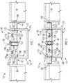
FIG. 1 is an end view of a portion of a cargo loading system having a locking pin assembly in a locked position; -
FIG. 2 is an end view of the portion of the cargo loading system having the locking pin assembly in an unlocked position; -
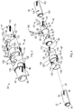
FIG. 3 is a perspective view of the locking pin assembly; -
FIG. 4 is a disassembled view of the locking pin assembly; -
FIG. 5 is a perspective view of a line replaceable unit installed in a structural support member; -
FIG. 6 is an end view of the line replaceable unit installed in the structural support member while the locking pin assembly is in the locked position; and -
FIG. 7 is an end view of the line replaceable unit while the locking pin assembly is in the unlocked position. - A detailed description of one or more embodiments of the disclosed apparatus and method are presented herein by way of exemplification and not limitation with reference to the Figures.
- Referring to
FIGS. 1, 2 ,5 ,6, and 7 , acargo loading system 10 may be provided with an aircraft or other vehicle. Thecargo loading system 10 may include components such as restraints, latches, or guides that are considered linereplaceable units 14, as shown inFIGS. 5-7 . These linereplaceable units 14 are mounted on or in astructural support member 12 by afastening assembly 16 that extends through a portion of the linereplaceable unit 14 and into the structural support member and by a locking pin assembly that extends through another portion of the linereplaceable unit 14 and into the structural support member. Thefastening assembly 16 may include a bolt, a bushing, and a nut. Thestructural support member 12 may be referred to as a tray or a ball panel having afirst sidewall 20, asecond sidewall 22 disposed opposite thefirst sidewall 20, and afloor 24 extending between thefirst sidewall 20 and thesecond sidewall 22. - The
first sidewall 20 of thestructural support member 12 may include ananti-rotation feature 26. Theanti-rotation feature 26 extends away from thefirst sidewall 20 towards thesecond sidewall 22. Theanti-rotation feature 26 may be spaced apart from thefloor 24. Theanti-rotation feature 26 may be a protrusion, a tab, a weld nut, or the like, that extends towards and engages a flat or a portion of a locking pin assembly to inhibit rotation of at least a portion of a locking pin assembly about an axis. - The line
replaceable units 14 may be removed from the first orsecond sidewall structural support member 12 and replaced/reinstalled with thestructural support member 12 within a specified amount of time. The linereplaceable units 14 may require the use of specialized tools to remove and replace individual linereplaceable units 14. An operator may manually lock and unlock the individual linereplaceable units 14 from thestructural support member 12, which may involve a time-consuming process and errors may result in failures of the linereplaceable units 14. Accordingly, it is desirable to provide alocking pin assembly 30 that may ease installation and removal of the linereplaceable units 14 as well as mitigate errors that may result in failures or incorrect installation of the linereplaceable units 14. - The
locking pin assembly 30 is arranged to selectively secure a linereplaceable unit 14 to thestructural support member 12. Thelocking pin assembly 30 extends along afirst axis 32. Thelocking pin assembly 30 is movable between a locked position, as shown inFIGS. 1 ,5 , and6 , and an unlocked position, as shown inFIGS. 2 and7 , by rotating at least a portion of thelocking pin assembly 30 about thefirst axis 32. - Referring to
FIGS. 1-7 , thelocking pin assembly 30 includes ashaft 40, afirst retention pin 42, asecond retention pin 44, asynchronizer 46, afirst guide pin 48, and asecond guide pin 50. - The
shaft 40 extends between afirst shaft end 60 and a second shaft end 62 along thefirst axis 32. Referring toFIG. 4 , theshaft 40 defines afirst shaft groove 64 that is disposed proximate thefirst shaft end 60 and asecond shaft groove 66 that is disposed proximate thesecond shaft end 62. - The
first shaft groove 64 may be spaced apart from thesecond shaft groove 66. Thefirst shaft groove 64 and thesecond shaft groove 66 are arranged as guide grooves or guide openings that extend from an exterior surface of theshaft 40 towards thefirst axis 32. Thefirst shaft groove 64 and thesecond shaft groove 66 are disposed in a non-parallel and non-perpendicular relationship with respect to thefirst axis 32 and each other. Thefirst shaft groove 64 and thesecond shaft groove 66 include afirst groove end 70, asecond groove end 72, andgroove walls 74 that extend between thefirst groove end 70 and thesecond groove end 72. - The
shaft 40 defines a shaft opening 80 that extends from an exterior surface of theshaft 40 towards thefirst axis 32 along asecond axis 82. The shaft opening 80 is disposed between thefirst shaft groove 64 and thesecond shaft groove 66. - The
shaft 40 defines arecessed region 84. Therecessed region 84 circumferentially extends about the exterior surface of theshaft 40 and radially extends from the exterior surface of theshaft 40 towards thefirst axis 32. The recessedregion 84 is axially disposed between the first groove ends 70 of thefirst shaft groove 64 and thesecond shaft groove 66. - The
shaft 40 defines a complementary anti-rotation feature or a flat 86 that is disposed proximate thefirst shaft end 60, as shown inFIGS. 1 and5 . The flat 86 of theshaft 40 is arranged to engage theanti-rotation feature 26 to inhibit rotation of theshaft 40 about thefirst axis 32. - Referring to
FIGS. 1-7 , thefirst retention pin 42 is slidably and rotatably received within theshaft 40. Thefirst retention pin 42 extends at least partially through thefirst shaft end 60. Thefirst retention pin 42 is arranged to move along thefirst axis 32 relative to thefirst shaft end 60 or thefirst sidewall 20, in response to rotation of thesynchronizer 46 about thefirst axis 32 to move the lockingpin assembly 30 between the locked position and the unlocked position. - Referring to
FIG. 4 , thefirst retention pin 42 extends between a first retention pinfirst end 90 and a first retention pinsecond end 92 along thefirst axis 32. The first retention pinsecond end 92 extends into theshaft 40. Thefirst retention pin 42 defines a first pin opening 94 that is disposed proximate the first retention pinsecond end 92. The first pin opening 94 is proximately aligned with thefirst shaft groove 64. - Referring to
FIGS. 1-7 , thesecond retention pin 44 is slidably and rotatably received within theshaft 40. Thesecond retention pin 44 extends at least partially through thesecond shaft end 62. Thesecond retention pin 44 is arranged to move along thefirst axis 32 relative to thesecond shaft end 62 or thesecond sidewall 22, in response to rotation of thesynchronizer 46 about thefirst axis 32 to move the lockingpin assembly 30 between the locked position and the unlocked position. - Referring to
FIG. 4 , thesecond retention pin 44 extends between a second retention pinfirst end 100 and a second retention pinsecond end 102 along thefirst axis 32. The second retention pinsecond end 102 extends into theshaft 40. Thesecond retention pin 44 defines a second pin opening 104 that is disposed proximate the second retention pinsecond end 102. The second pin opening 104 is proximately aligned with thesecond shaft groove 66. - The
synchronizer 46 is disposed about theshaft 40, thefirst retention pin 42, and thesecond retention pin 44. Thesynchronizer 46 is rotatable about thefirst axis 32 relative to theshaft 40. Thesynchronizer 46 is rotatable between a first position that corresponds to the locked position of the lockingpin assembly 30 and a second position that corresponds to the unlocked position of the lockingpin assembly 30. - Referring to
FIGS. 1-7 , thesynchronizer 46 extends between afirst synchronizer end 110 and asecond synchronizer end 112 along thefirst axis 32. Thesynchronizer 46 defines afirst synchronizer groove 114 that is disposed proximate thefirst synchronizer end 110 and asecond synchronizer groove 116 that is disposed proximate thesecond synchronizer end 112. Thefirst synchronizer groove 114 is partially aligned with or crosses over thefirst shaft groove 64. Thesecond synchronizer groove 116 is partially aligned or crosses over with thesecond shaft groove 66. - The
first synchronizer groove 114 may be spaced apart from thesecond synchronizer groove 116. Thefirst synchronizer groove 114 and thesecond synchronizer groove 116 are arranged as guide openings that extend from an exterior surface of thesynchronizer 46 towards theshaft 40 and thefirst axis 32. Thefirst synchronizer groove 114 and thesecond synchronizer groove 116 are disposed in a non-parallel and non-perpendicular relationship with respect to thefirst axis 32, with respect to the each and with respect to thefirst shaft groove 64 and thesecond shaft groove 66. - The
first synchronizer groove 114 is angled in an opposite direction as thefirst shaft groove 64 and thesecond synchronizer groove 116 is angled in an opposite direction as thesecond shaft groove 66. Thefirst synchronizer groove 114 and thesecond synchronizer groove 116 include a firstsynchronizer groove end 120, a secondsynchronizer groove end 122, andsynchronizer groove walls 124 that extend between the firstsynchronizer groove end 120 and the secondsynchronizer groove end 122. - The
synchronizer 46 includes a first tab orfirst extension 130 that extends from thefirst synchronizer end 110. Thefirst extension 130 enables at least a portion of thefirst shaft end 60 to be exposed. Thesynchronizer 46 includes a second tab or asecond extension 132 that extends from thesecond synchronizer end 112. Thesecond extension 132 enables at least a portion of thesecond shaft end 62 to be exposed. - The
synchronizer 46 defines asynchronizer opening 140 that extends from an exterior surface of thesynchronizer 46 towards thefirst axis 32 along thesecond axis 82. Thesynchronizer opening 140 is disposed between thefirst synchronizer groove 114 and thesecond synchronizer groove 116. Thesynchronizer opening 140 is proximately aligned with theshaft opening 80 along thesecond axis 82 while thesynchronizer 46 is in the first position and the lockingpin assembly 30 is in the locked position. Thesynchronizer opening 140 is not aligned with or is circumferentially offset from theshaft opening 80 while thesynchronizer 46 is in the second position and the lockingpin assembly 30 is in the unlocked position. - The
synchronizer 46 includes a raisedportion 142 that circumferentially extends about thesynchronizer 46. The raisedportion 142 is axially disposed between the firstsynchronizer groove end 120 of thefirst synchronizer groove 114 and thesecond synchronizer groove 116. The raisedportion 142 radially extends away from thefirst axis 32. In at least one embodiment, thesynchronizer opening 140 extends through the raisedportion 142 along thesecond axis 82. - A
fastener 150 extends through theshaft opening 80 and into thesynchronizer opening 140 maintain or lock thelocking pin assembly 30 in the locked position, as shown inFIGS. 1 and3 . Thefastener 150 may be a self-locking screw. Awasher 152 may be provided along with thefastener 150 that is disposed between a head of thefastener 150 and thesynchronizer 46. Thefastener 150 may extend at least partially through theshaft opening 80 and is inhibited from extending into thesynchronizer opening 140 and may extend into the recessedregion 84 of theshaft 40, to inhibit the lockingpin assembly 30 from being in the unlocked position. Upon rotation of thesynchronizer 46 from the second position towards the first position, thefastener 150 is enabled to extend through theshaft opening 80 and into thesynchronizer opening 140 to lock thelocking pin assembly 30 in the locked position. - The
first guide pin 48 extends through thefirst shaft groove 64 of theshaft 40, thefirst synchronizer groove 114 of thesynchronizer 46, and extends into the first pin opening 94 of thefirst retention pin 42. Thefirst guide pin 48 may be disposed proximate the secondsynchronizer groove end 122 of thefirst synchronizer groove 114, while the lockingpin assembly 30 is in the locked position, as shown inFIGS. 1 and3 . Thefirst guide pin 48 may be disposed proximate the firstsynchronizer groove end 120 of thefirst synchronizer groove 114, while the lockingpin assembly 30 is in the unlocked position, as shown inFIG. 2 . - The
second guide pin 50 extends through thesecond shaft groove 66 of theshaft 40, thesecond synchronizer groove 116 of thesynchronizer 46, and extends into the second pin opening 104 of thesecond retention pin 44. Thesecond guide pin 50 may be disposed proximate the secondsynchronizer groove end 122 of thesecond synchronizer groove 116, while the lockingpin assembly 30 is in the locked position, as shown inFIGS. 1 and3 . Thesecond guide pin 50 may be disposed proximate the firstsynchronizer groove end 120 of thesecond synchronizer groove 116, while the lockingpin assembly 30 is in the unlocked position, as shown inFIG. 2 . - Responsive to rotation of the
synchronizer 46 about thefirst axis 32, the lockingpin assembly 30 moves between the unlocked position and the locked position and at least one of thefirst retention pin 42 moves relative to thefirst shaft end 60 and/or thefirst sidewall 20 and thesecond retention pin 44 moves relative to thesecond shaft end 62 and/or thesecond sidewall 22. - The grooves of the shaft 40 (e.g. the
first shaft groove 64 and the second shaft groove 66) and the grooves of the synchronizer 46 (e.g. thefirst synchronizer groove 114 and the second synchronizer groove 116) are arranged as guide grooves that cross over each other such that the guide pins (e.g. thefirst guide pin 48 and the second guide pin 50) are forced inwards or outwards responsive to rotation of thesynchronizer 46. The crossing over of the guide grooves in response to rotation of the synchronizer in a first direction forces the guide pins on both sides of the lockingpin assembly 30 to be guided outwards to force the retention pins (e.g. thefirst retention pin 42 and the second retention pin 44) outwards to lock thelocking pin assembly 30 in a locked position. The crossing over of the guide grooves in response to rotation of the synchronizer in a second direction forces the guide pins on both sides of the lockingpin assembly 30 to be guided inwards to force the retention pins (e.g. thefirst retention pin 42 and the second retention pin 44) inwards to place the lockingpin assembly 30 in an unlocked position. - Responsive to rotation of the
synchronizer 46 in a first direction about thefirst axis 32, e.g. from the unlocked position towards the locked position, the guide grooves of theshaft 40 and thesynchronizer 46 cross over each other, forcing the guide pins on both sides to be guided outwards to force the retention pins outwards, locking the line replaceable unit. Therefore, thefirst guide pin 48 rides along a groove wall of at least one of thefirst shaft groove 64 and thefirst synchronizer groove 114, such that a first retention pinfirst end 90 moves towards and/or into thefirst sidewall 20 of thestructural support member 12. Thesecond guide pin 50 also rides along or relative to a groove wall of at least one of thesecond shaft groove 66 and thesecond synchronizer groove 116, such that the second retention pinfirst end 100 moves towards and/or into thesecond sidewall 22 of thestructural support member 12. - Responsive to rotation of the
synchronizer 46 in a second direction, which is disposed opposite the first direction, about thefirst axis 32, e.g. from the locked position towards the unlocked position, the guide grooves of theshaft 40 and thesynchronizer 46 cross over each other, pulling the guide pins on both sides inwards to draw the retention pins inwards, unlocking the linereplaceable unit 14. Thefirst guide pin 48 rides along or relative to a groove wall of at least one of thefirst shaft groove 64 and thefirst synchronizer groove 114, such that a first retention pinfirst end 90 moves away from thefirst sidewall 20 of thestructural support member 12, towards thefirst synchronizer end 110. Thesecond guide pin 50 also rides along a groove wall of at least one of thesecond shaft groove 66 and thesecond synchronizer groove 116, such that the second retention pinfirst end 100 moves away from thesecond sidewall 22 of thestructural support member 12, towards thesecond synchronizer end 112. - The locking
pin assembly 30 is arranged as a synchronous locking pin assembly that synchronously moves thefirst retention pin 42 and thesecond retention pin 44 along thefirst axis 32 relative to walls of thestructural support members 12. In some embodiments, indicators may be disposed on the exterior surface of thesynchronizer 46 to provide an indication of the locked position and the unlocked position of the lockingpin assembly 30. - The synchronous
locking pin assembly 30 enables an operator to rotate and tighten thefastener 150 to lock and unlock the lockingpin assembly 30. This reduces installation and removal time of the linereplaceable unit 14. The synchronous locking pin assembly also enables single hand procedures to be performed instead of two-handed procedures. The synchronous locking pin assembly also is less prone to errors, as incorrect extension in locking of retention pins is inhibited. - The term "about" is intended to include the degree of error associated with measurement of the particular quantity based upon the equipment available at the time of filing the application.
- The terminology used herein is for the purpose of describing particular embodiments only and is not intended to be limiting of the present disclosure. As used herein, the singular forms "a", "an" and "the" are intended to include the plural forms as well, unless the context clearly indicates otherwise. It will be further understood that the terms "comprises" and/or "comprising," when used in this specification, specify the presence of stated features, integers, steps, operations, elements, and/or components, but do not preclude the presence or addition of one or more other features, integers, steps, operations, element components, and/or groups thereof.
- While the present disclosure has been described with reference to an exemplary embodiment or embodiments, it will be understood by those skilled in the art that various changes may be made and equivalents may be substituted for elements thereof without departing from the scope of the present disclosure. In addition, many modifications may be made to adapt a particular situation or material to the teachings of the present disclosure without departing from the essential scope thereof. Therefore, it is intended that the present disclosure not be limited to the particular embodiment disclosed as the best mode contemplated for carrying out this present disclosure, but that the present disclosure will include all embodiments falling within the scope of the claims.
Claims (15)
- A cargo loading system (10), comprising:a structural support member (12) having a first sidewall (20), a second sidewall (22) disposed opposite the first sidewall (20), and a floor extending between the first sidewall and the second sidewall; anda locking pin assembly (30) arranged to secure a line replaceable unit to the structural support member (12), the locking pin assembly (30) comprising:a shaft (40) extending between a first shaft end (60) and a second shaft end (62) along a first axis (32),a first retention pin (42) disposed within the shaft (40) and extending at least partially through the first shaft end (60),a second retention pin (44) disposed within the shaft (12) and extending at least partially through the second shaft end, anda synchronizer (46) disposed about the shaft (12), the synchronizer extending between a first synchronizer end (110) and a second synchronizer end (112) along the first axis (32), responsive to rotation of the synchronizer (46) about the first axis (32), the first retention pin (42) moves relative to the first shaft end (60) and the first sidewall along the first axis (32).
- The cargo loading system of claim 1, wherein the shaft (12) defines a first shaft groove (114) and a second shaft groove (66) that is spaced apart from the first shaft groove (64).
- The cargo loading system of claim 2, the synchronizer (46) defines a first synchronizer groove (114) partially aligned with the first shaft groove (64) and a second synchronizer groove (116) partially aligned with the second shaft groove (66).
- The cargo loading system of claim 3, wherein the locking pin assembly (30) further comprising: a first guide pin (48) extends through the first shaft groove, the first synchronizer groove, and into the first retention pin.
- The cargo loading system of claim 4, wherein in response to rotation of the synchronizer (46) in a first direction about the first axis (32), the first guide pin rides along at least one of the first shaft groove (64) and the first synchronizer groove (114)), such that an end of the first guide pin (48) moves towards the first sidewall of the structural support member, and optionally wherein in response to rotation of the synchronizer (46) in a second direction about the first axis (32), the first guide pin (48) rides along at least one of the first shaft groove (64) and the first synchronizer groove (114), such that the end of the first guide pin (48) moves away from the first sidewall of the structural support member.
- The cargo loading system of claim 3, wherein the locking pin assembly (30) further comprising: a second guide pin (50) extends through the second shaft groove (66), the second synchronizer groove (116), and into the second retention pin (44).
- The cargo loading system of claim 6, wherein in response to rotation of the synchronizer (46) in a first direction about the first axis (32), the second guide pin (50)) rides along at least one of the second shaft groove and the second synchronizer groove, such that an end of the second guide pin (50) moves towards the second sidewall of the structural support member, and optionally wherein in response to rotation of the synchronizer (46) in a second direction about the first axis (32), the second guide pin (50) rides along at least one of the second shaft groove (66) and the second synchronizer groove (116), such that the end of the second guide pin moves away from the second sidewall of the structural support member.
- The cargo loading system of any preceding claim, wherein the shaft (40) defines a flat that is disposed proximate the first shaft end (60), and optionally wherein the first sidewall of the structural support member includes an anti-rotation feature that extends towards and engages the flat to inhibit rotation of the shaft (40) about the first axis (32).
- A locking pin assembly (30) for a cargo loading system, comprising:a shaft (40) extending between a first shaft end (60) and a second shaft end (62) along a first axis, the shaft (40) defines a first shaft groove (64) disposed proximate the first shaft end (66) and a second shaft groove (66) disposed proximate the second shaft end;a first retention pin (42) disposed within the shaft (40);a second retention pin (44) disposed within the shaft (40); anda synchronizer (46) disposed about the shaft, the synchronizer (46) extending between a first synchronizer end (110) and a second synchronizer end (112) along the first axis (32), the synchronizer (46) defines a first synchronizer groove (114) that crosses over the first shaft groove (64) and a second synchronizer groove (116) that crosses over the second shaft groove.
- The locking pin assembly of claim 9, wherein the shaft (40) defines a shaft opening (140) that extends along a second axis that is disposed transverse to the first axis (32).
- The locking pin assembly of claim 10, wherein the synchronizer (46) defines a synchronizer opening.
- The locking pin assembly of claim 11, wherein the synchronizer (46) is rotatable about the first axis between a first position and a second position.
- The locking pin assembly of claim 12, wherein while the synchronizer (46) is in the first position the shaft opening is proximately aligned with the synchronizer (46) opening along the second axis, or wherein while the synchronizer (46) is in the second position, the shaft opening (80) is offset from the synchronizer opening (140).
- The locking pin assembly of claim 12, wherein responsive to rotation of the synchronizer (46) between the first position and the second position, at least one of the first retention pin (42) moves relative to the first shaft end and the second retention pin (44) moves relative to the second shaft end.
- The locking pin assembly of any of claims 9 to 14, further comprising: a first guide pin extends through the first shaft groove (64), the first synchronizer groove, and into the first retention pin (42), or further comprising: a second guide pin extends through the second shaft groove (66), the second synchronizer groove, and into the second retention pin (44).
Applications Claiming Priority (1)
| Application Number | Priority Date | Filing Date | Title |
|---|---|---|---|
| IN201811022356 | 2018-06-14 |
Publications (2)
| Publication Number | Publication Date |
|---|---|
| EP3581495A1 true EP3581495A1 (en) | 2019-12-18 |
| EP3581495B1 EP3581495B1 (en) | 2021-11-03 |
Family
ID=66866922
Family Applications (1)
| Application Number | Title | Priority Date | Filing Date |
|---|---|---|---|
| EP19179704.2A Not-in-force EP3581495B1 (en) | 2018-06-14 | 2019-06-12 | Synchronous locking pin assembly |
Country Status (2)
| Country | Link |
|---|---|
| US (1) | US11072425B2 (en) |
| EP (1) | EP3581495B1 (en) |
Families Citing this family (3)
| Publication number | Priority date | Publication date | Assignee | Title |
|---|---|---|---|---|
| US12234031B2 (en) * | 2021-08-09 | 2025-02-25 | Goodrich Corporation | Cargo restraint system with individually retractable restraints |
| US12252267B2 (en) | 2021-11-16 | 2025-03-18 | Goodrich Corporation | Restraint system utilizing co-axial actuation |
| WO2025261788A1 (en) * | 2024-06-20 | 2025-12-26 | Shl Medical Ag | A connector assembly |
Citations (5)
| Publication number | Priority date | Publication date | Assignee | Title |
|---|---|---|---|---|
| US3377040A (en) * | 1966-12-05 | 1968-04-09 | Boeing Co | Retractable cargo securing device |
| US3800713A (en) * | 1973-01-18 | 1974-04-02 | A Nordstrom | Self-erecting cargo pallet lock |
| US3810534A (en) * | 1970-04-22 | 1974-05-14 | Ancra Corp | Automatic pallet locking device |
| FR2907757A1 (en) * | 2006-10-30 | 2008-05-02 | Goodrich Corp | Unit load device (ULD) guide for use when loading cargo onto aircraft has main body which has one planar guide surface that is pivoted to the arm and is movable between two guide positions |
| US20150113839A1 (en) * | 2013-10-30 | 2015-04-30 | Hensley Industries, Inc. | Static Locking Apparatus for Rotatable Connector Pin Assembly |
Family Cites Families (5)
| Publication number | Priority date | Publication date | Assignee | Title |
|---|---|---|---|---|
| US4077590A (en) | 1976-03-11 | 1978-03-07 | The Boeing Company | Integrated treadway cargo handling system |
| US4234278A (en) * | 1978-10-31 | 1980-11-18 | Electro-Pneumatic International Gmbh | Locking devices for cargo and the like |
| DE4210703C2 (en) * | 1992-04-01 | 1994-02-03 | Deutsche Aerospace Airbus | Locking element |
| US9695972B1 (en) | 2016-05-25 | 2017-07-04 | Panasonic Avionics Corporation | Quick-release mounting system for removably attaching a panel instrument to a structure |
| US10118700B2 (en) * | 2016-10-12 | 2018-11-06 | Goodrich Corporation | SMA actuated restraint assembly |
-
2018
- 2018-12-17 US US16/221,974 patent/US11072425B2/en not_active Expired - Fee Related
-
2019
- 2019-06-12 EP EP19179704.2A patent/EP3581495B1/en not_active Not-in-force
Patent Citations (5)
| Publication number | Priority date | Publication date | Assignee | Title |
|---|---|---|---|---|
| US3377040A (en) * | 1966-12-05 | 1968-04-09 | Boeing Co | Retractable cargo securing device |
| US3810534A (en) * | 1970-04-22 | 1974-05-14 | Ancra Corp | Automatic pallet locking device |
| US3800713A (en) * | 1973-01-18 | 1974-04-02 | A Nordstrom | Self-erecting cargo pallet lock |
| FR2907757A1 (en) * | 2006-10-30 | 2008-05-02 | Goodrich Corp | Unit load device (ULD) guide for use when loading cargo onto aircraft has main body which has one planar guide surface that is pivoted to the arm and is movable between two guide positions |
| US20150113839A1 (en) * | 2013-10-30 | 2015-04-30 | Hensley Industries, Inc. | Static Locking Apparatus for Rotatable Connector Pin Assembly |
Also Published As
| Publication number | Publication date |
|---|---|
| US11072425B2 (en) | 2021-07-27 |
| EP3581495B1 (en) | 2021-11-03 |
| US20190382117A1 (en) | 2019-12-19 |
Similar Documents
| Publication | Publication Date | Title |
|---|---|---|
| EP3581495B1 (en) | Synchronous locking pin assembly | |
| EP3848283B1 (en) | Adjustable restraint assemblies | |
| US9695972B1 (en) | Quick-release mounting system for removably attaching a panel instrument to a structure | |
| CN101784802B (en) | Riveting screw tack and use thereof for temporarily fixing a boring grid to elements to be assembled | |
| US4856738A (en) | Adjustable seating arrangement for aircraft | |
| EP1251043B1 (en) | Unit comprising airbag and steering wheel | |
| WO2013192193A1 (en) | Sequential latch for palletized cargo | |
| CN109204832B (en) | Rotationally engaged quick-install track fitting | |
| EP2427681B1 (en) | Side-locking clamping apparatus and method | |
| JP6129644B2 (en) | Wall installation system and method | |
| EP2734404B1 (en) | Holding device for an adjustment drive of a motor vehicle seat | |
| EP0235333A1 (en) | Reference platform for an arrestable alignment | |
| EP2248760B1 (en) | Method and device for filling components with supplies on automobile industry production lines | |
| EP3446975A1 (en) | Intelligent lock for cargo handling system | |
| US9896184B2 (en) | Locking apparatus and method | |
| US11137011B2 (en) | Fastening system for fastening a first component at a variable spacing on a second component | |
| DE102011010699B4 (en) | Fitting for a vehicle seat and vehicle seat with such a fitting | |
| JP2011529829A (en) | Device for removably securing a seat | |
| WO2014035241A1 (en) | Locking assembly for locking an aircraft interior structure to an aircraft main support structure | |
| EP2996926B1 (en) | Fastening device and locking device | |
| EP3315408B1 (en) | Seat rail adapter comprising two mounting parts, seat rail and cabin arrangement comprising such a seat rail adapter | |
| CN110116380B (en) | Tool for rotating fastener, method for using tool and method for manufacturing tool | |
| US20200317056A1 (en) | Machine console system | |
| JP2018062333A (en) | Sidewall mounting hardware for aircraft | |
| EP3159109A1 (en) | System and method for nut swaging verification |
Legal Events
| Date | Code | Title | Description |
|---|---|---|---|
| PUAI | Public reference made under article 153(3) epc to a published international application that has entered the european phase |
Free format text: ORIGINAL CODE: 0009012 |
|
| STAA | Information on the status of an ep patent application or granted ep patent |
Free format text: STATUS: THE APPLICATION HAS BEEN PUBLISHED |
|
| AK | Designated contracting states |
Kind code of ref document: A1 Designated state(s): AL AT BE BG CH CY CZ DE DK EE ES FI FR GB GR HR HU IE IS IT LI LT LU LV MC MK MT NL NO PL PT RO RS SE SI SK SM TR |
|
| AX | Request for extension of the european patent |
Extension state: BA ME |
|
| RIN1 | Information on inventor provided before grant (corrected) |
Inventor name: CHITRAGAR, VENKATESH Inventor name: SHIVALINGA, VINODKUMAR |
|
| STAA | Information on the status of an ep patent application or granted ep patent |
Free format text: STATUS: REQUEST FOR EXAMINATION WAS MADE |
|
| 17P | Request for examination filed |
Effective date: 20200615 |
|
| RBV | Designated contracting states (corrected) |
Designated state(s): AL AT BE BG CH CY CZ DE DK EE ES FI FR GB GR HR HU IE IS IT LI LT LU LV MC MK MT NL NO PL PT RO RS SE SI SK SM TR |
|
| GRAP | Despatch of communication of intention to grant a patent |
Free format text: ORIGINAL CODE: EPIDOSNIGR1 |
|
| STAA | Information on the status of an ep patent application or granted ep patent |
Free format text: STATUS: GRANT OF PATENT IS INTENDED |
|
| INTG | Intention to grant announced |
Effective date: 20201208 |
|
| GRAJ | Information related to disapproval of communication of intention to grant by the applicant or resumption of examination proceedings by the epo deleted |
Free format text: ORIGINAL CODE: EPIDOSDIGR1 |
|
| STAA | Information on the status of an ep patent application or granted ep patent |
Free format text: STATUS: REQUEST FOR EXAMINATION WAS MADE |
|
| INTC | Intention to grant announced (deleted) | ||
| GRAP | Despatch of communication of intention to grant a patent |
Free format text: ORIGINAL CODE: EPIDOSNIGR1 |
|
| STAA | Information on the status of an ep patent application or granted ep patent |
Free format text: STATUS: GRANT OF PATENT IS INTENDED |
|
| INTG | Intention to grant announced |
Effective date: 20210526 |
|
| GRAS | Grant fee paid |
Free format text: ORIGINAL CODE: EPIDOSNIGR3 |
|
| GRAA | (expected) grant |
Free format text: ORIGINAL CODE: 0009210 |
|
| STAA | Information on the status of an ep patent application or granted ep patent |
Free format text: STATUS: THE PATENT HAS BEEN GRANTED |
|
| AK | Designated contracting states |
Kind code of ref document: B1 Designated state(s): AL AT BE BG CH CY CZ DE DK EE ES FI FR GB GR HR HU IE IS IT LI LT LU LV MC MK MT NL NO PL PT RO RS SE SI SK SM TR |
|
| REG | Reference to a national code |
Ref country code: GB Ref legal event code: FG4D |
|
| REG | Reference to a national code |
Ref country code: AT Ref legal event code: REF Ref document number: 1443753 Country of ref document: AT Kind code of ref document: T Effective date: 20211115 Ref country code: CH Ref legal event code: EP |
|
| REG | Reference to a national code |
Ref country code: DE Ref legal event code: R096 Ref document number: 602019008855 Country of ref document: DE |
|
| REG | Reference to a national code |
Ref country code: IE Ref legal event code: FG4D |
|
| REG | Reference to a national code |
Ref country code: LT Ref legal event code: MG9D |
|
| REG | Reference to a national code |
Ref country code: NL Ref legal event code: MP Effective date: 20211103 |
|
| REG | Reference to a national code |
Ref country code: AT Ref legal event code: MK05 Ref document number: 1443753 Country of ref document: AT Kind code of ref document: T Effective date: 20211103 |
|
| PG25 | Lapsed in a contracting state [announced via postgrant information from national office to epo] |
Ref country code: RS Free format text: LAPSE BECAUSE OF FAILURE TO SUBMIT A TRANSLATION OF THE DESCRIPTION OR TO PAY THE FEE WITHIN THE PRESCRIBED TIME-LIMIT Effective date: 20211103 Ref country code: LT Free format text: LAPSE BECAUSE OF FAILURE TO SUBMIT A TRANSLATION OF THE DESCRIPTION OR TO PAY THE FEE WITHIN THE PRESCRIBED TIME-LIMIT Effective date: 20211103 Ref country code: FI Free format text: LAPSE BECAUSE OF FAILURE TO SUBMIT A TRANSLATION OF THE DESCRIPTION OR TO PAY THE FEE WITHIN THE PRESCRIBED TIME-LIMIT Effective date: 20211103 Ref country code: BG Free format text: LAPSE BECAUSE OF FAILURE TO SUBMIT A TRANSLATION OF THE DESCRIPTION OR TO PAY THE FEE WITHIN THE PRESCRIBED TIME-LIMIT Effective date: 20220203 Ref country code: AT Free format text: LAPSE BECAUSE OF FAILURE TO SUBMIT A TRANSLATION OF THE DESCRIPTION OR TO PAY THE FEE WITHIN THE PRESCRIBED TIME-LIMIT Effective date: 20211103 |
|
| PG25 | Lapsed in a contracting state [announced via postgrant information from national office to epo] |
Ref country code: IS Free format text: LAPSE BECAUSE OF FAILURE TO SUBMIT A TRANSLATION OF THE DESCRIPTION OR TO PAY THE FEE WITHIN THE PRESCRIBED TIME-LIMIT Effective date: 20220303 Ref country code: SE Free format text: LAPSE BECAUSE OF FAILURE TO SUBMIT A TRANSLATION OF THE DESCRIPTION OR TO PAY THE FEE WITHIN THE PRESCRIBED TIME-LIMIT Effective date: 20211103 Ref country code: PT Free format text: LAPSE BECAUSE OF FAILURE TO SUBMIT A TRANSLATION OF THE DESCRIPTION OR TO PAY THE FEE WITHIN THE PRESCRIBED TIME-LIMIT Effective date: 20220303 Ref country code: PL Free format text: LAPSE BECAUSE OF FAILURE TO SUBMIT A TRANSLATION OF THE DESCRIPTION OR TO PAY THE FEE WITHIN THE PRESCRIBED TIME-LIMIT Effective date: 20211103 Ref country code: NO Free format text: LAPSE BECAUSE OF FAILURE TO SUBMIT A TRANSLATION OF THE DESCRIPTION OR TO PAY THE FEE WITHIN THE PRESCRIBED TIME-LIMIT Effective date: 20220203 Ref country code: NL Free format text: LAPSE BECAUSE OF FAILURE TO SUBMIT A TRANSLATION OF THE DESCRIPTION OR TO PAY THE FEE WITHIN THE PRESCRIBED TIME-LIMIT Effective date: 20211103 Ref country code: LV Free format text: LAPSE BECAUSE OF FAILURE TO SUBMIT A TRANSLATION OF THE DESCRIPTION OR TO PAY THE FEE WITHIN THE PRESCRIBED TIME-LIMIT Effective date: 20211103 Ref country code: HR Free format text: LAPSE BECAUSE OF FAILURE TO SUBMIT A TRANSLATION OF THE DESCRIPTION OR TO PAY THE FEE WITHIN THE PRESCRIBED TIME-LIMIT Effective date: 20211103 Ref country code: GR Free format text: LAPSE BECAUSE OF FAILURE TO SUBMIT A TRANSLATION OF THE DESCRIPTION OR TO PAY THE FEE WITHIN THE PRESCRIBED TIME-LIMIT Effective date: 20220204 Ref country code: ES Free format text: LAPSE BECAUSE OF FAILURE TO SUBMIT A TRANSLATION OF THE DESCRIPTION OR TO PAY THE FEE WITHIN THE PRESCRIBED TIME-LIMIT Effective date: 20211103 |
|
| PG25 | Lapsed in a contracting state [announced via postgrant information from national office to epo] |
Ref country code: SM Free format text: LAPSE BECAUSE OF FAILURE TO SUBMIT A TRANSLATION OF THE DESCRIPTION OR TO PAY THE FEE WITHIN THE PRESCRIBED TIME-LIMIT Effective date: 20211103 Ref country code: SK Free format text: LAPSE BECAUSE OF FAILURE TO SUBMIT A TRANSLATION OF THE DESCRIPTION OR TO PAY THE FEE WITHIN THE PRESCRIBED TIME-LIMIT Effective date: 20211103 Ref country code: RO Free format text: LAPSE BECAUSE OF FAILURE TO SUBMIT A TRANSLATION OF THE DESCRIPTION OR TO PAY THE FEE WITHIN THE PRESCRIBED TIME-LIMIT Effective date: 20211103 Ref country code: EE Free format text: LAPSE BECAUSE OF FAILURE TO SUBMIT A TRANSLATION OF THE DESCRIPTION OR TO PAY THE FEE WITHIN THE PRESCRIBED TIME-LIMIT Effective date: 20211103 Ref country code: DK Free format text: LAPSE BECAUSE OF FAILURE TO SUBMIT A TRANSLATION OF THE DESCRIPTION OR TO PAY THE FEE WITHIN THE PRESCRIBED TIME-LIMIT Effective date: 20211103 Ref country code: CZ Free format text: LAPSE BECAUSE OF FAILURE TO SUBMIT A TRANSLATION OF THE DESCRIPTION OR TO PAY THE FEE WITHIN THE PRESCRIBED TIME-LIMIT Effective date: 20211103 |
|
| PGFP | Annual fee paid to national office [announced via postgrant information from national office to epo] |
Ref country code: FR Payment date: 20220519 Year of fee payment: 4 Ref country code: DE Payment date: 20220518 Year of fee payment: 4 |
|
| REG | Reference to a national code |
Ref country code: DE Ref legal event code: R097 Ref document number: 602019008855 Country of ref document: DE |
|
| PLBE | No opposition filed within time limit |
Free format text: ORIGINAL CODE: 0009261 |
|
| STAA | Information on the status of an ep patent application or granted ep patent |
Free format text: STATUS: NO OPPOSITION FILED WITHIN TIME LIMIT |
|
| 26N | No opposition filed |
Effective date: 20220804 |
|
| PG25 | Lapsed in a contracting state [announced via postgrant information from national office to epo] |
Ref country code: AL Free format text: LAPSE BECAUSE OF FAILURE TO SUBMIT A TRANSLATION OF THE DESCRIPTION OR TO PAY THE FEE WITHIN THE PRESCRIBED TIME-LIMIT Effective date: 20211103 |
|
| PG25 | Lapsed in a contracting state [announced via postgrant information from national office to epo] |
Ref country code: SI Free format text: LAPSE BECAUSE OF FAILURE TO SUBMIT A TRANSLATION OF THE DESCRIPTION OR TO PAY THE FEE WITHIN THE PRESCRIBED TIME-LIMIT Effective date: 20211103 |
|
| PG25 | Lapsed in a contracting state [announced via postgrant information from national office to epo] |
Ref country code: MC Free format text: LAPSE BECAUSE OF FAILURE TO SUBMIT A TRANSLATION OF THE DESCRIPTION OR TO PAY THE FEE WITHIN THE PRESCRIBED TIME-LIMIT Effective date: 20211103 |
|
| REG | Reference to a national code |
Ref country code: CH Ref legal event code: PL |
|
| REG | Reference to a national code |
Ref country code: BE Ref legal event code: MM Effective date: 20220630 |
|
| PG25 | Lapsed in a contracting state [announced via postgrant information from national office to epo] |
Ref country code: LU Free format text: LAPSE BECAUSE OF NON-PAYMENT OF DUE FEES Effective date: 20220612 Ref country code: LI Free format text: LAPSE BECAUSE OF NON-PAYMENT OF DUE FEES Effective date: 20220630 Ref country code: IE Free format text: LAPSE BECAUSE OF NON-PAYMENT OF DUE FEES Effective date: 20220612 Ref country code: CH Free format text: LAPSE BECAUSE OF NON-PAYMENT OF DUE FEES Effective date: 20220630 |
|
| PG25 | Lapsed in a contracting state [announced via postgrant information from national office to epo] |
Ref country code: IT Free format text: LAPSE BECAUSE OF FAILURE TO SUBMIT A TRANSLATION OF THE DESCRIPTION OR TO PAY THE FEE WITHIN THE PRESCRIBED TIME-LIMIT Effective date: 20211103 Ref country code: BE Free format text: LAPSE BECAUSE OF NON-PAYMENT OF DUE FEES Effective date: 20220630 |
|
| REG | Reference to a national code |
Ref country code: DE Ref legal event code: R119 Ref document number: 602019008855 Country of ref document: DE |
|
| GBPC | Gb: european patent ceased through non-payment of renewal fee |
Effective date: 20230612 |
|
| PG25 | Lapsed in a contracting state [announced via postgrant information from national office to epo] |
Ref country code: MK Free format text: LAPSE BECAUSE OF FAILURE TO SUBMIT A TRANSLATION OF THE DESCRIPTION OR TO PAY THE FEE WITHIN THE PRESCRIBED TIME-LIMIT Effective date: 20211103 Ref country code: DE Free format text: LAPSE BECAUSE OF NON-PAYMENT OF DUE FEES Effective date: 20240103 Ref country code: CY Free format text: LAPSE BECAUSE OF FAILURE TO SUBMIT A TRANSLATION OF THE DESCRIPTION OR TO PAY THE FEE WITHIN THE PRESCRIBED TIME-LIMIT Effective date: 20211103 Ref country code: GB Free format text: LAPSE BECAUSE OF NON-PAYMENT OF DUE FEES Effective date: 20230612 |
|
| PG25 | Lapsed in a contracting state [announced via postgrant information from national office to epo] |
Ref country code: HU Free format text: LAPSE BECAUSE OF FAILURE TO SUBMIT A TRANSLATION OF THE DESCRIPTION OR TO PAY THE FEE WITHIN THE PRESCRIBED TIME-LIMIT; INVALID AB INITIO Effective date: 20190612 Ref country code: FR Free format text: LAPSE BECAUSE OF NON-PAYMENT OF DUE FEES Effective date: 20230630 |
|
| PG25 | Lapsed in a contracting state [announced via postgrant information from national office to epo] |
Ref country code: TR Free format text: LAPSE BECAUSE OF FAILURE TO SUBMIT A TRANSLATION OF THE DESCRIPTION OR TO PAY THE FEE WITHIN THE PRESCRIBED TIME-LIMIT Effective date: 20211103 |
|
| PG25 | Lapsed in a contracting state [announced via postgrant information from national office to epo] |
Ref country code: MT Free format text: LAPSE BECAUSE OF FAILURE TO SUBMIT A TRANSLATION OF THE DESCRIPTION OR TO PAY THE FEE WITHIN THE PRESCRIBED TIME-LIMIT Effective date: 20211103 |