EP3581386A1 - Wiper for nozzle plates - Google Patents
Wiper for nozzle plates Download PDFInfo
- Publication number
- EP3581386A1 EP3581386A1 EP18177330.0A EP18177330A EP3581386A1 EP 3581386 A1 EP3581386 A1 EP 3581386A1 EP 18177330 A EP18177330 A EP 18177330A EP 3581386 A1 EP3581386 A1 EP 3581386A1
- Authority
- EP
- European Patent Office
- Prior art keywords
- wiper
- nozzle plate
- nozzle
- edge
- active
- Prior art date
- Legal status (The legal status is an assumption and is not a legal conclusion. Google has not performed a legal analysis and makes no representation as to the accuracy of the status listed.)
- Granted
Links
Images



Classifications
-
- B—PERFORMING OPERATIONS; TRANSPORTING
- B41—PRINTING; LINING MACHINES; TYPEWRITERS; STAMPS
- B41J—TYPEWRITERS; SELECTIVE PRINTING MECHANISMS, i.e. MECHANISMS PRINTING OTHERWISE THAN FROM A FORME; CORRECTION OF TYPOGRAPHICAL ERRORS
- B41J2/00—Typewriters or selective printing mechanisms characterised by the printing or marking process for which they are designed
- B41J2/005—Typewriters or selective printing mechanisms characterised by the printing or marking process for which they are designed characterised by bringing liquid or particles selectively into contact with a printing material
- B41J2/01—Ink jet
- B41J2/135—Nozzles
- B41J2/165—Prevention or detection of nozzle clogging, e.g. cleaning, capping or moistening for nozzles
- B41J2/16517—Cleaning of print head nozzles
- B41J2/16552—Cleaning of print head nozzles using cleaning fluids
-
- B—PERFORMING OPERATIONS; TRANSPORTING
- B41—PRINTING; LINING MACHINES; TYPEWRITERS; STAMPS
- B41J—TYPEWRITERS; SELECTIVE PRINTING MECHANISMS, i.e. MECHANISMS PRINTING OTHERWISE THAN FROM A FORME; CORRECTION OF TYPOGRAPHICAL ERRORS
- B41J2/00—Typewriters or selective printing mechanisms characterised by the printing or marking process for which they are designed
- B41J2/005—Typewriters or selective printing mechanisms characterised by the printing or marking process for which they are designed characterised by bringing liquid or particles selectively into contact with a printing material
- B41J2/01—Ink jet
- B41J2/135—Nozzles
- B41J2/165—Prevention or detection of nozzle clogging, e.g. cleaning, capping or moistening for nozzles
- B41J2/16517—Cleaning of print head nozzles
- B41J2/16535—Cleaning of print head nozzles using wiping constructions
- B41J2/16538—Cleaning of print head nozzles using wiping constructions with brushes or wiper blades perpendicular to the nozzle plate
-
- B—PERFORMING OPERATIONS; TRANSPORTING
- B41—PRINTING; LINING MACHINES; TYPEWRITERS; STAMPS
- B41J—TYPEWRITERS; SELECTIVE PRINTING MECHANISMS, i.e. MECHANISMS PRINTING OTHERWISE THAN FROM A FORME; CORRECTION OF TYPOGRAPHICAL ERRORS
- B41J2/00—Typewriters or selective printing mechanisms characterised by the printing or marking process for which they are designed
- B41J2/005—Typewriters or selective printing mechanisms characterised by the printing or marking process for which they are designed characterised by bringing liquid or particles selectively into contact with a printing material
- B41J2/01—Ink jet
- B41J2/135—Nozzles
- B41J2/165—Prevention or detection of nozzle clogging, e.g. cleaning, capping or moistening for nozzles
- B41J2/16517—Cleaning of print head nozzles
- B41J2/16535—Cleaning of print head nozzles using wiping constructions
- B41J2/16544—Constructions for the positioning of wipers
-
- B—PERFORMING OPERATIONS; TRANSPORTING
- B41—PRINTING; LINING MACHINES; TYPEWRITERS; STAMPS
- B41J—TYPEWRITERS; SELECTIVE PRINTING MECHANISMS, i.e. MECHANISMS PRINTING OTHERWISE THAN FROM A FORME; CORRECTION OF TYPOGRAPHICAL ERRORS
- B41J2/00—Typewriters or selective printing mechanisms characterised by the printing or marking process for which they are designed
- B41J2/005—Typewriters or selective printing mechanisms characterised by the printing or marking process for which they are designed characterised by bringing liquid or particles selectively into contact with a printing material
- B41J2/01—Ink jet
- B41J2/135—Nozzles
- B41J2/165—Prevention or detection of nozzle clogging, e.g. cleaning, capping or moistening for nozzles
- B41J2/16517—Cleaning of print head nozzles
- B41J2/16552—Cleaning of print head nozzles using cleaning fluids
- B41J2002/16558—Using cleaning liquid for wet wiping
Definitions
- the invention relates to a wiper for a nozzle plate, the wiper having a body arranged to be moved over a nozzle face of the nozzle plate in a condition in which at least a part of the body is in engagement with the nozzle plate, the body having at least one active wiper edge that extends in a direction in parallel with the nozzle face and non-parallel with a direction of movement of the body relative to the nozzle plate.
- a nozzle plate is employed for example in an ink jet printer and has a nozzle face formed with a plurality of nozzles from which droplets of ink can be ejected in order to print an image on a recording medium. Similar nozzle plates may also be used in other types of droplet ejection devices.
- the nozzle face may become contaminated with dried ink, dust, condensed water or other materials which may compromise the process of droplet formation and droplet ejection. It is therefore necessary to clean the nozzle face from time to time by means of a wiper.
- a commonly used wiping method is contact wiping, wherein the active wiper edge is held in contact with the nozzle face while the wiper is moved along the nozzle plate.
- This method is suitable for removing even contaminants that adhere to the nozzle face relatively strongly.
- this method has the drawback that the direct contact of the wiper with the nozzle face leads to increased wear of the nozzle face, which is particularly undesired if the nozzle face has a coating such as an anti-wetting coating or a wetting coating.
- An alternative wiping method is contactless wiping wherein the wiper is moved over the nozzle face in a posture in which the active wiper edge is separated from the nozzle face by a gap the width of which is so small that liquid (e.g. ink) is held in the gap by capillary forces. Consequently, when the wiper is moved over the nozzle plate, a slug of liquid will move over the nozzle face together with the active wiper edge, and this liquid will be active to gently remove contaminants from the nozzle face even though there is no direct contact between the active wiper edge and the nozzle face.
- liquid e.g. ink
- the body has at least one support part that is offset from the active wiper edge in the direction of movement and arranged to engage the nozzle plate at least during the movement of the body over the nozzle face in one direction.
- the contactless wiping method may be performed by holding the wiper in a posture in which the support part or support parts engage the nozzle plate and keep the active wiper edge separated from the nozzle face by the desired gap while the wiper is moved over the nozzle plate.
- the wiper is held in a posture in which the support part or support parts are spaced apart from the nozzle plate and the wiper engages the nozzle face only with its active edge.
- the wiper may be made of a resilient material, e.g. a rubber-elastic material. Then, friction between the nozzle plate and a part of the wiper - either the support part or the active edge - will cause the wiper to be deflected in the direction opposite to the direction in which the wiper is moved over the nozzle plate. Consequently, the posture of the wiper will depend upon the direction of movement. When the wiper moves in the direction in which the support part is ahead of the active edge, the wiper will flex into the contactless wiping posture. Conversely, when the wiper moves in the opposite direction, it will flex into the contact wiping posture.
- a resilient material e.g. a rubber-elastic material
- Another possibility to control the posture of the wiper is to adjust the inclination of the wiper relative to the nozzle plate by means of a suitable holder.
- the posture of the wiper may be controlled by controlling the force with which the wiper is pressed against the nozzle plate.
- the support part or support parts will be offset from the active wiper edge not only in the direction of movement but also in the direction normal to the nozzle face. Consequently, when the wiper is pressed against the nozzle plate only gently, the active wiper edge will be held in contact with the nozzle face while the support part or support parts are spaced apart from the nozzle plate.
- the wiper when the wiper is pressed against the nozzle plate with a larger force, the wiper will bend to a larger extent, so that the support part or support parts will come into engagement with the nozzle plate and keep the active wiper edge away from the nozzle face.
- Fig. 1 shows an example of a wiper 10 that is made of a slab of a suitable rubber-elastic material having a generally rectangular shape.
- a root portion 12 which may be held in a holder 14, as has been shown in Fig. 2 .
- the end of the wiper that is opposite to the root portion 12 is rounded off on one side, so that a straight and relatively sharp active wiper edge 16 is formed on the opposite side of the slab.
- a recess 18 has been formed in a central part of the slab on the rounded side thereof.
- a bottom surface 18a of the recess 18 has been shaped such that, when going from the active edge 16 towards the root portion 12, the cross-sectional width of the slab initially decreases faster in the area of the recess 18 than in the parts of the wiper outside of the recess. Then, further down towards the root portion 12, the bottom surface of the recess 18 merges again with the flat surface of the slab.
- the portions of the wiper 10 that are left on both sides of the recess 18 constitute support parts 20 which, depending upon the posture of the wiper 10 relative to a nozzle plate 22 (shown in Fig. 2 ), may engage the surface of the nozzle plate and keep the active edge 16 away from a central region of the nozzle plate.
- Fig. 2 shows a portion of the nozzle plate 22 in a side view.
- a number of nozzles 24 arranged in a linear array on a bottom side of the nozzle plate 22 and opening out in a nozzle face 26 of the nozzle plate have been shown in phantom lines.
- the root portion of the wiper 10 is held in the holder 14 which, in the condition shown in Fig. 2 , moves in a direction A relative to the nozzle plate 22.
- the direction of movement A is parallel with the array of nozzles 24.
- the support parts 20 engage the nozzle plate 22, and the friction between these support parts and the nozzle plate 22 cause the wiper 10 to bend in the direction opposite to the direction of movement A.
- the active wiper edge 16, which extends in parallel with the nozzle face 26 (in the direction normal the plane of the drawing in Fig. 2 ) is kept away from the nozzle face 26.
- the bottom surface 18a of the recess 18 is also kept away from the nozzle face 26, so that the bottom surface 18a and the nozzle face 26 form a gap 28 with substantially constant height that extends over the entire width of the recess 18.
- the nozzle face 26 has a wetting coating so that it is wetted with liquid ink that is expelled from the nozzles 24. As a consequence, a certain amount of ink will remain on the nozzle face 26 and will form a pool around each of the nozzles 24.
- the width of the gap 28 has been selected such that the bottom surface 18a of the recess 18 comes into contact with these pools of ink, so that capillary forces between the ink and the nozzle face 26 on the one hand and the ink and the bottom surface 18a of the recess of the wiper 10 on the other hand hold a slug of ink in the gap 28, and when the wiper and the holder 14 move in the direction A, this slug of ink will move together with the wiper and will thus wipe the nozzle face 26 so as to remove any possible contaminants even without direct contact between the active wiper edge and the nozzle face.
- Fig. 3 shows a condition in which the holder 14 and the wiper 10 move in a direction B opposite to the direction A.
- frictional forces between the nozzle plate 22 and the wiper 10 cause the wiper to bend in opposite direction, so that the wiper engages the nozzle face 26 with its active edge 16 whereas the support parts 20 are kept away from the nozzle plate.
- the nozzle face 16 is wiped mechanically with the active edge 16 of the wiper so that even strongly adhering contaminants can be removed.
- either of the wiping modes illustrated in Figs. 2 and 3 may be selected in accordance with the demand. For example, most of the wiping operations may be performed in the contactless mode shown in Fig. 2 , by gently pressing the holder 14 against the nozzle plate 22 during the movement of the holder in the direction A and withdrawing the holder and the wiper from the nozzle plate during the reverse movement. Consequently, those parts of the nozzle face 26 which surround the nozzles 24 do not come into direct contact with the wiper 10, so that wear of the coating on the nozzle face is reduced to minimum.
- the wiper is set against the nozzle face 26 during movement in the direction B.
- Fig. 4 is a cross-sectional view of the nozzle plate 22 and shows the wiper 10 in a front view as seen in the direction B.
- the wiper is operated in the contactless mode, i.e. it is moved over the nozzle plate in the direction A, i.e. towards the viewer in Fig. 4 , so that the wiper engages the lateral parts of the nozzle face 26 with the support parts 20, whereas the central part of the wiper is separated by the gap 28 from the central part of the nozzle face that contains the nozzles 24.
- Fig. 5 is a perspective view of a wiper 10' according to a modified embodiment wherein the support parts 20 are formed by bumps that project from a front face of the wiper 10 on the side opposite to the side that forms the active edge 16.
- a holder 14' may be arranged to adjust the angle at which the wiper 10' is inclined relative to the nozzle plate 22. In the condition shown in Fig. 6 , the wiper is in the contactless mode and engages the nozzle plate 22 only with the support parts 20.
- the holder 14' is moved in the direction A in this mode in order to reduce the friction between the wiper and the nozzle plate.
- a contactless wiping operation might also be performed by "pushing" the wiper 10' in the opposite direction B.
- the wiper 10' In order to switch to the contact mode, the wiper 10' is tilted into a more upright position, so that it engages the nozzle face 26 with its active edge 16.
- Fig. 7 shows a wiper 10" which differs from the wiper 10' according to Fig. 5 in that the support parts 20 are arranged on the same side of the slab as the active 16. Further, the support parts 20 are offset from the active edge 16 not only in the direction (A or B) of movement of the wiper 10" but also in the (vertical) direction towards the root portion 12 of the wiper.
- the mode of operation may be switched between the contact mode and the contactless mode by controlling the force with which the wiper 10" is pressed against the nozzle plate.
- Fig. 8 illustrates the contact mode in which the holder 14 is arranged to press the wiper 10" against the nozzle plate 22 only with a gentle force, so that, even during a movement in the direction A, the amount of deflection of the wiper 10" is so small that the wiper engages the nozzle face 26 only with its active edge 16 whereas the support parts 20 are kept away from the nozzle plate.
- Fig. 10 is a sectional view of a wiper 10'" according to another embodiment which is based on the same design principle as the wiper 10" shown in Fig. 7 but has two active edges 16 and two pairs of support parts 20 in a symmetric configuration, so that both the contactless mode and the contact mode may be performed during movement of the wiper relative to the nozzle plate in any of the directions A and B.
- a nozzle plate 22' may also have guide portions 30 formed on either side of the nozzle face 26, the surfaces of these guide portions 30 being offset from the nozzle face 26 in the direction normal to the nozzle face and being engaged by the support parts 20 of a wiper 10 IV .
- the wiper has the active edge 16 formed on a projecting part that projects into the space between the two guides portions 30.
- Fig. 11 shows the wiper in the contactless mode, where the support parts 20 engage the guide portions 30 whereas the active edge 16 is spaced apart from the nozzle face 26.
- the contact mode may be established by tilting the wiper such that the active edge 16 comes into contact with the nozzle face 26 and the support parts 20 are lifted off from the guide portions 30.
- a nozzle face 26 comprises a plurality (i.e. at least two) of parallel nozzle arrays, the plurality of parallel nozzle arrays being arranged at a relatively large distance from one another
- a plurality of additional support parts (besides the ones indicated with 20) may be provided to the body of the wiper and arranged in between support parts 20, such that in wiping contact, the plurality of support parts contact the nozzle face in between the plurality of nozzle arrays. Additional advantage in this embodiment is that the bridged length is smaller with multiple support parts (each nozzle array is separately bridged), hence the created gap over the nozzle array with the (resilient) wiper has a more constant height.
Landscapes
- Ink Jet (AREA)
Abstract
Description
- The invention relates to a wiper for a nozzle plate, the wiper having a body arranged to be moved over a nozzle face of the nozzle plate in a condition in which at least a part of the body is in engagement with the nozzle plate, the body having at least one active wiper edge that extends in a direction in parallel with the nozzle face and non-parallel with a direction of movement of the body relative to the nozzle plate.
- A nozzle plate is employed for example in an ink jet printer and has a nozzle face formed with a plurality of nozzles from which droplets of ink can be ejected in order to print an image on a recording medium. Similar nozzle plates may also be used in other types of droplet ejection devices.
- During extended operation of the device, the nozzle face may become contaminated with dried ink, dust, condensed water or other materials which may compromise the process of droplet formation and droplet ejection. It is therefore necessary to clean the nozzle face from time to time by means of a wiper.
- A commonly used wiping method is contact wiping, wherein the active wiper edge is held in contact with the nozzle face while the wiper is moved along the nozzle plate. This method is suitable for removing even contaminants that adhere to the nozzle face relatively strongly. However, this method has the drawback that the direct contact of the wiper with the nozzle face leads to increased wear of the nozzle face, which is particularly undesired if the nozzle face has a coating such as an anti-wetting coating or a wetting coating.
- An alternative wiping method is contactless wiping wherein the wiper is moved over the nozzle face in a posture in which the active wiper edge is separated from the nozzle face by a gap the width of which is so small that liquid (e.g. ink) is held in the gap by capillary forces. Consequently, when the wiper is moved over the nozzle plate, a slug of liquid will move over the nozzle face together with the active wiper edge, and this liquid will be active to gently remove contaminants from the nozzle face even though there is no direct contact between the active wiper edge and the nozzle face.
- It is an object of the invention to provide a wiper with a design that is suitable for both wiping methods.
- According to the invention, in order to achieve this object, the body has at least one support part that is offset from the active wiper edge in the direction of movement and arranged to engage the nozzle plate at least during the movement of the body over the nozzle face in one direction.
- With this wiper, the contactless wiping method may be performed by holding the wiper in a posture in which the support part or support parts engage the nozzle plate and keep the active wiper edge separated from the nozzle face by the desired gap while the wiper is moved over the nozzle plate. In order to perform the contact wiping method, the wiper is held in a posture in which the support part or support parts are spaced apart from the nozzle plate and the wiper engages the nozzle face only with its active edge.
- More specific optional features of the invention are indicated in the dependent claims.
- The wiper may be made of a resilient material, e.g. a rubber-elastic material. Then, friction between the nozzle plate and a part of the wiper - either the support part or the active edge - will cause the wiper to be deflected in the direction opposite to the direction in which the wiper is moved over the nozzle plate. Consequently, the posture of the wiper will depend upon the direction of movement. When the wiper moves in the direction in which the support part is ahead of the active edge, the wiper will flex into the contactless wiping posture. Conversely, when the wiper moves in the opposite direction, it will flex into the contact wiping posture.
- Another possibility to control the posture of the wiper is to adjust the inclination of the wiper relative to the nozzle plate by means of a suitable holder.
- In yet another embodiment, the posture of the wiper may be controlled by controlling the force with which the wiper is pressed against the nozzle plate. In that case, the support part or support parts will be offset from the active wiper edge not only in the direction of movement but also in the direction normal to the nozzle face. Consequently, when the wiper is pressed against the nozzle plate only gently, the active wiper edge will be held in contact with the nozzle face while the support part or support parts are spaced apart from the nozzle plate. However, when the wiper is pressed against the nozzle plate with a larger force, the wiper will bend to a larger extent, so that the support part or support parts will come into engagement with the nozzle plate and keep the active wiper edge away from the nozzle face.
- Embodiment examples will now be described in conjunction with the drawings, wherein:
- Fig. 1
- is a perspective view of a wiper according to an embodiment of the invention;
- Fig. 2
- is a sectional view of the wiper shown in
Fig. 1 , in a condition in which the wiper moves along a nozzle plate in a first direction; - Fig. 3
- is a sectional view of the wiper in a condition in which the wiper moves along the nozzle plate in opposite direction;
- Fig. 4
- is a front view of the wiper shown in
Fig. 1 and a cross-sectional view of the nozzle plate; - Fig. 5
- is a perspective view of a wiper according to a modified embodiment;
- Fig. 6
- is a sectional view of the wiper shown in
Fig. 5 , in a condition in which the wiper moves along the nozzle plate; - Fig. 7
- is a perspective view of a wiper according to yet another embodiment of the invention;
- Fig. 8
- is a sectional view of the wiper shown in
Fig. 7 and a part of the nozzle plate in a contact wiping mode; - Fig. 9
- is a sectional view of the wiper and the nozzle plate in a contactless wiping mode;
- Fig. 10
- is a sectional view of a wiper according to yet another embodiment; and
- Fig. 11
- is a front view of a wiper which is configured as in
Figs. 7 or10 , but cooperating with a nozzle plate with a different design. -
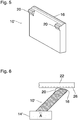
Fig. 1 shows an example of awiper 10 that is made of a slab of a suitable rubber-elastic material having a generally rectangular shape. One of the longer sides of the rectangle constitutes aroot portion 12 which may be held in aholder 14, as has been shown inFig. 2 . The end of the wiper that is opposite to theroot portion 12 is rounded off on one side, so that a straight and relatively sharpactive wiper edge 16 is formed on the opposite side of the slab. - Closely adjacent to the
active edge 16, arecess 18 has been formed in a central part of the slab on the rounded side thereof. Abottom surface 18a of therecess 18 has been shaped such that, when going from theactive edge 16 towards theroot portion 12, the cross-sectional width of the slab initially decreases faster in the area of therecess 18 than in the parts of the wiper outside of the recess. Then, further down towards theroot portion 12, the bottom surface of therecess 18 merges again with the flat surface of the slab. - The portions of the
wiper 10 that are left on both sides of therecess 18 constitutesupport parts 20 which, depending upon the posture of thewiper 10 relative to a nozzle plate 22 (shown inFig. 2 ), may engage the surface of the nozzle plate and keep theactive edge 16 away from a central region of the nozzle plate. -
Fig. 2 shows a portion of thenozzle plate 22 in a side view. A number ofnozzles 24 arranged in a linear array on a bottom side of thenozzle plate 22 and opening out in anozzle face 26 of the nozzle plate have been shown in phantom lines. - The root portion of the
wiper 10 is held in theholder 14 which, in the condition shown inFig. 2 , moves in a direction A relative to thenozzle plate 22. The direction of movement A is parallel with the array ofnozzles 24. Thesupport parts 20 engage thenozzle plate 22, and the friction between these support parts and thenozzle plate 22 cause thewiper 10 to bend in the direction opposite to the direction of movement A. As a consequence, theactive wiper edge 16, which extends in parallel with the nozzle face 26 (in the direction normal the plane of the drawing inFig. 2 ) is kept away from thenozzle face 26. - As can further be seen in
Fig. 2 , thebottom surface 18a of therecess 18 is also kept away from thenozzle face 26, so that thebottom surface 18a and thenozzle face 26 form agap 28 with substantially constant height that extends over the entire width of therecess 18. - It may be assumed in this example that the
nozzle face 26 has a wetting coating so that it is wetted with liquid ink that is expelled from thenozzles 24. As a consequence, a certain amount of ink will remain on thenozzle face 26 and will form a pool around each of thenozzles 24. The width of thegap 28 has been selected such that thebottom surface 18a of therecess 18 comes into contact with these pools of ink, so that capillary forces between the ink and thenozzle face 26 on the one hand and the ink and thebottom surface 18a of the recess of thewiper 10 on the other hand hold a slug of ink in thegap 28, and when the wiper and theholder 14 move in the direction A, this slug of ink will move together with the wiper and will thus wipe thenozzle face 26 so as to remove any possible contaminants even without direct contact between the active wiper edge and the nozzle face. -
Fig. 3 shows a condition in which theholder 14 and thewiper 10 move in a direction B opposite to the direction A. In this case, frictional forces between thenozzle plate 22 and thewiper 10 cause the wiper to bend in opposite direction, so that the wiper engages thenozzle face 26 with itsactive edge 16 whereas thesupport parts 20 are kept away from the nozzle plate. Under these conditions, thenozzle face 16 is wiped mechanically with theactive edge 16 of the wiper so that even strongly adhering contaminants can be removed. - During operation of a print head that has the
nozzle plate 22, either of the wiping modes illustrated inFigs. 2 and 3 may be selected in accordance with the demand. For example, most of the wiping operations may be performed in the contactless mode shown inFig. 2 , by gently pressing theholder 14 against thenozzle plate 22 during the movement of the holder in the direction A and withdrawing the holder and the wiper from the nozzle plate during the reverse movement. Consequently, those parts of thenozzle face 26 which surround thenozzles 24 do not come into direct contact with thewiper 10, so that wear of the coating on the nozzle face is reduced to minimum. - From time to time, it may however be desired to perform a wiping operation in the contact mode shown in
Fig. 3 in order to remove contaminants that adhere to the nozzle face so strongly that they cannot be removed in the contactless mode. In that case, the wiper is set against thenozzle face 26 during movement in the direction B. -
Fig. 4 is a cross-sectional view of thenozzle plate 22 and shows thewiper 10 in a front view as seen in the direction B. InFig. 4 , the wiper is operated in the contactless mode, i.e. it is moved over the nozzle plate in the direction A, i.e. towards the viewer inFig. 4 , so that the wiper engages the lateral parts of thenozzle face 26 with thesupport parts 20, whereas the central part of the wiper is separated by thegap 28 from the central part of the nozzle face that contains thenozzles 24. -
Fig. 5 is a perspective view of awiper 10' according to a modified embodiment wherein thesupport parts 20 are formed by bumps that project from a front face of thewiper 10 on the side opposite to the side that forms theactive edge 16. In this embodiment, as is shown inFig. 6 , a holder 14' may be arranged to adjust the angle at which thewiper 10' is inclined relative to thenozzle plate 22. In the condition shown inFig. 6 , the wiper is in the contactless mode and engages thenozzle plate 22 only with thesupport parts 20. - It will generally be preferred that the holder 14' is moved in the direction A in this mode in order to reduce the friction between the wiper and the nozzle plate. In principle, however, a contactless wiping operation might also be performed by "pushing" the
wiper 10' in the opposite direction B. - In order to switch to the contact mode, the
wiper 10' is tilted into a more upright position, so that it engages thenozzle face 26 with itsactive edge 16. - As another embodiment,
Fig. 7 shows awiper 10" which differs from thewiper 10' according toFig. 5 in that thesupport parts 20 are arranged on the same side of the slab as the active 16. Further, thesupport parts 20 are offset from theactive edge 16 not only in the direction (A or B) of movement of thewiper 10" but also in the (vertical) direction towards theroot portion 12 of the wiper. - In this embodiment, the mode of operation may be switched between the contact mode and the contactless mode by controlling the force with which the
wiper 10" is pressed against the nozzle plate. -
Fig. 8 illustrates the contact mode in which theholder 14 is arranged to press thewiper 10" against thenozzle plate 22 only with a gentle force, so that, even during a movement in the direction A, the amount of deflection of thewiper 10" is so small that the wiper engages thenozzle face 26 only with itsactive edge 16 whereas thesupport parts 20 are kept away from the nozzle plate. - On the other hand, when the
holder 14 is arranged to be closer to thenozzle plate 22, as shown inFig. 9 , the relative movement of the wiper in the direction A causes a larger deflection of the wiper and the point of contact between the wiper and thenozzle plate 22 shifts from theactive edge 16 to thesupport parts 20. As a result, the wiper is deflected even further, so that theactive edge 16 is separated from thenozzle face 26 by a gap with suitable width for the contactless wiping mode. -
Fig. 10 is a sectional view of awiper 10'" according to another embodiment which is based on the same design principle as thewiper 10" shown inFig. 7 but has twoactive edges 16 and two pairs ofsupport parts 20 in a symmetric configuration, so that both the contactless mode and the contact mode may be performed during movement of the wiper relative to the nozzle plate in any of the directions A and B. - In the examples that have been described so far, it has been assumed that the
nozzle plate 22 has a flat bottom surface constituting thenozzle face 26. However, as is shown inFig. 11 , a nozzle plate 22' may also haveguide portions 30 formed on either side of thenozzle face 26, the surfaces of theseguide portions 30 being offset from thenozzle face 26 in the direction normal to the nozzle face and being engaged by thesupport parts 20 of awiper 10IV. In that case, the wiper has theactive edge 16 formed on a projecting part that projects into the space between the twoguides portions 30.Fig. 11 shows the wiper in the contactless mode, where thesupport parts 20 engage theguide portions 30 whereas theactive edge 16 is spaced apart from thenozzle face 26. The contact mode may be established by tilting the wiper such that theactive edge 16 comes into contact with thenozzle face 26 and thesupport parts 20 are lifted off from theguide portions 30.
In case anozzle face 26 comprises a plurality (i.e. at least two) of parallel nozzle arrays, the plurality of parallel nozzle arrays being arranged at a relatively large distance from one another, a plurality of additional support parts (besides the ones indicated with 20) may be provided to the body of the wiper and arranged in betweensupport parts 20, such that in wiping contact, the plurality of support parts contact the nozzle face in between the plurality of nozzle arrays. Additional advantage in this embodiment is that the bridged length is smaller with multiple support parts (each nozzle array is separately bridged), hence the created gap over the nozzle array with the (resilient) wiper has a more constant height.
Claims (9)
- A wiper (10; 10'; 10"; 10"'; 10IV) for a nozzle plate (22; 22'), the wiper having a body arranged to be moved over a nozzle face (26) of the nozzle plate (22; 22') in a condition in which at least a part of the body is in engagement with the nozzle plate, the body having at least one active wiper edge (16) that extends in a direction in parallel with the nozzle face (26) and non-parallel with a direction (A, B) of movement of the body relative to the nozzle plate, characterized in that the body has at least one support part (20) that is offset from the active wiper edge (16) in the direction (A, B) of movement and arranged to engage the nozzle plate (22; 22') at least during the movement of the body over the nozzle face (26) in one direction.
- The wiper according to claim 1, wherein the body of the wiper is made of a resilient material.
- The wiper (10) according to claim 1 or 2, wherein an edge of the wiper body is rounded off on one side so as to form an acute active edge (16) on the opposite side, and wherein two support parts (20) are formed by two edge portions of the body on the rounded-off side, the support parts (20) being separated by a recess (18) formed adjacent to the active edge (16).
- The wiper (10') according to claim 1 or 2, wherein an edge of the wiper body is rounded off on one side so as to form an acute active edge (16) on the other side, and two support parts (20) are formed by bumps projecting from the surface of the wiper body on the side that is rounded-off.
- The wiper (10"; 10'") according to claim 1 or 2, wherein the support parts (20) and the active edge (16) are formed on the same side of the wiper body, and the support parts (20) are formed by bumps projecting from the surface of the wiper body and offset from the active edge (16) in a direction normal to the active edge and in parallel with the side of the wiper body that forms the active edge.
- A nozzle plate and wiper assembly comprising a nozzle plate (22; 22'), the wiper ((10; 10'; 10"; 10'"; 10IV) according to any of the claims 1 to 5, and a holder (14; 14') for the wiper, wherein the holder (14; 14') is arranged to hold the wiper (10; 10'; 10"; 10'"; 10IV) against the nozzle plate (22; 22') while the holder moves in a first direction (A) of movement relative to the nozzle plate and to hold the wiper in a position withdrawn from the nozzle plate (22) while the holder moves in a second direction (B) opposite to that first direction.
- The nozzle plate and wiper assembly according to claim 6, wherein the holder (14') is arranged to adjust an angle of inclination of the wiper (10') relative to the nozzle plate (22).
- The nozzle plate and wiper assembly according to claim 6 or 7, wherein the holder (14) is arranged to adjust a pressure with which the wiper (10"; 10'") is pressed against the nozzle plate (22).
- The nozzle plate and wiper assembly according to any of the claims 6 to 8, wherein the nozzle plate (22) has an array of nozzles (24), and the support parts (20) of the wiper (10; 10'; 10") are arranged to engage the nozzle face (26) of the nozzle plate (22) on opposite sides of the nozzle array.
Priority Applications (1)
| Application Number | Priority Date | Filing Date | Title |
|---|---|---|---|
| EP18177330.0A EP3581386B1 (en) | 2018-06-12 | 2018-06-12 | Wiper for nozzle plates |
Applications Claiming Priority (1)
| Application Number | Priority Date | Filing Date | Title |
|---|---|---|---|
| EP18177330.0A EP3581386B1 (en) | 2018-06-12 | 2018-06-12 | Wiper for nozzle plates |
Publications (2)
| Publication Number | Publication Date |
|---|---|
| EP3581386A1 true EP3581386A1 (en) | 2019-12-18 |
| EP3581386B1 EP3581386B1 (en) | 2022-09-14 |
Family
ID=62620772
Family Applications (1)
| Application Number | Title | Priority Date | Filing Date |
|---|---|---|---|
| EP18177330.0A Active EP3581386B1 (en) | 2018-06-12 | 2018-06-12 | Wiper for nozzle plates |
Country Status (1)
| Country | Link |
|---|---|
| EP (1) | EP3581386B1 (en) |
Citations (5)
| Publication number | Priority date | Publication date | Assignee | Title |
|---|---|---|---|---|
| JP2000006437A (en) * | 1998-06-18 | 2000-01-11 | Seiko Epson Corp | Ink jet recording device |
| JP2002178527A (en) * | 2000-12-14 | 2002-06-26 | Seiko Epson Corp | Ink jet recording device and cleaning blade |
| JP2007203679A (en) * | 2006-02-03 | 2007-08-16 | Roland Dg Corp | Blade member used for wiper device in ink jet printer |
| US20080291239A1 (en) * | 2007-03-22 | 2008-11-27 | Yoshirou Kita | Inkjet recording apparatus |
| JP2010005857A (en) * | 2008-06-25 | 2010-01-14 | Fujifilm Corp | Liquid discharge apparatus and head maintenance device |
-
2018
- 2018-06-12 EP EP18177330.0A patent/EP3581386B1/en active Active
Patent Citations (5)
| Publication number | Priority date | Publication date | Assignee | Title |
|---|---|---|---|---|
| JP2000006437A (en) * | 1998-06-18 | 2000-01-11 | Seiko Epson Corp | Ink jet recording device |
| JP2002178527A (en) * | 2000-12-14 | 2002-06-26 | Seiko Epson Corp | Ink jet recording device and cleaning blade |
| JP2007203679A (en) * | 2006-02-03 | 2007-08-16 | Roland Dg Corp | Blade member used for wiper device in ink jet printer |
| US20080291239A1 (en) * | 2007-03-22 | 2008-11-27 | Yoshirou Kita | Inkjet recording apparatus |
| JP2010005857A (en) * | 2008-06-25 | 2010-01-14 | Fujifilm Corp | Liquid discharge apparatus and head maintenance device |
Also Published As
| Publication number | Publication date |
|---|---|
| EP3581386B1 (en) | 2022-09-14 |
Similar Documents
| Publication | Publication Date | Title |
|---|---|---|
| US4959673A (en) | Ink jet recording apparatus | |
| US9409401B2 (en) | Wiper for an inkjet printer | |
| US5612722A (en) | Ink jet printhead wiper having side surfaces intersecting a top surface at acute angles to form wiping edges and a slat centered in a bottom surface | |
| US20010000434A1 (en) | Contoured cross-sectional wiper for cleaning inkjet printheads | |
| KR101445427B1 (en) | Recording apparatus | |
| US20120299996A1 (en) | Ink jet printing apparatus | |
| US20050062796A1 (en) | Wiper apparatus and method for cleaning a printhead | |
| JP3792543B2 (en) | Wiper for inkjet printer | |
| JP2009023118A (en) | Wiping method of ink jet recording head | |
| CN100999157B (en) | Wiping device and liquid spraying device | |
| US6123409A (en) | Inkjet printhead with capillary channels for receiving wiped ink and residue | |
| EP3581386B1 (en) | Wiper for nozzle plates | |
| US7004560B2 (en) | Cleaning device for cleaning inkjet head | |
| JP2011212902A (en) | Liquid jetting apparatus | |
| JP3359101B2 (en) | Ink jet recording device | |
| US9421778B2 (en) | Liquid discharge apparatus | |
| US6015203A (en) | Rubbing member for ink jet apparatus | |
| JP2004284352A (en) | Ink jet head cleaning device and ink jet recording device | |
| JPH05254137A (en) | Ink jet recording apparatus | |
| JP2009160786A (en) | Droplet discharge device | |
| JP6432264B2 (en) | Liquid ejection device | |
| JP2002127436A (en) | Ink-jet printer | |
| JP4427987B2 (en) | Liquid jet head wiping device and liquid jet device | |
| JP2000006437A (en) | Ink jet recording device | |
| JPH05104734A (en) | Ink jet recorder |
Legal Events
| Date | Code | Title | Description |
|---|---|---|---|
| PUAI | Public reference made under article 153(3) epc to a published international application that has entered the european phase |
Free format text: ORIGINAL CODE: 0009012 |
|
| STAA | Information on the status of an ep patent application or granted ep patent |
Free format text: STATUS: THE APPLICATION HAS BEEN PUBLISHED |
|
| AK | Designated contracting states |
Kind code of ref document: A1 Designated state(s): AL AT BE BG CH CY CZ DE DK EE ES FI FR GB GR HR HU IE IS IT LI LT LU LV MC MK MT NL NO PL PT RO RS SE SI SK SM TR |
|
| AX | Request for extension of the european patent |
Extension state: BA ME |
|
| RAP1 | Party data changed (applicant data changed or rights of an application transferred) |
Owner name: CANON PRODUCTION PRINTING HOLDING B.V. |
|
| STAA | Information on the status of an ep patent application or granted ep patent |
Free format text: STATUS: REQUEST FOR EXAMINATION WAS MADE |
|
| 17P | Request for examination filed |
Effective date: 20200618 |
|
| RBV | Designated contracting states (corrected) |
Designated state(s): AL AT BE BG CH CY CZ DE DK EE ES FI FR GB GR HR HU IE IS IT LI LT LU LV MC MK MT NL NO PL PT RO RS SE SI SK SM TR |
|
| RAP1 | Party data changed (applicant data changed or rights of an application transferred) |
Owner name: CANON PRODUCTION PRINTING HOLDING B.V. |
|
| GRAP | Despatch of communication of intention to grant a patent |
Free format text: ORIGINAL CODE: EPIDOSNIGR1 |
|
| STAA | Information on the status of an ep patent application or granted ep patent |
Free format text: STATUS: GRANT OF PATENT IS INTENDED |
|
| INTG | Intention to grant announced |
Effective date: 20220420 |
|
| GRAS | Grant fee paid |
Free format text: ORIGINAL CODE: EPIDOSNIGR3 |
|
| GRAA | (expected) grant |
Free format text: ORIGINAL CODE: 0009210 |
|
| STAA | Information on the status of an ep patent application or granted ep patent |
Free format text: STATUS: THE PATENT HAS BEEN GRANTED |
|
| AK | Designated contracting states |
Kind code of ref document: B1 Designated state(s): AL AT BE BG CH CY CZ DE DK EE ES FI FR GB GR HR HU IE IS IT LI LT LU LV MC MK MT NL NO PL PT RO RS SE SI SK SM TR |
|
| REG | Reference to a national code |
Ref country code: GB Ref legal event code: FG4D |
|
| REG | Reference to a national code |
Ref country code: CH Ref legal event code: EP |
|
| REG | Reference to a national code |
Ref country code: DE Ref legal event code: R096 Ref document number: 602018040573 Country of ref document: DE |
|
| REG | Reference to a national code |
Ref country code: IE Ref legal event code: FG4D |
|
| REG | Reference to a national code |
Ref country code: AT Ref legal event code: REF Ref document number: 1518474 Country of ref document: AT Kind code of ref document: T Effective date: 20221015 |
|
| REG | Reference to a national code |
Ref country code: NL Ref legal event code: FP |
|
| REG | Reference to a national code |
Ref country code: LT Ref legal event code: MG9D |
|
| PG25 | Lapsed in a contracting state [announced via postgrant information from national office to epo] |
Ref country code: SE Free format text: LAPSE BECAUSE OF FAILURE TO SUBMIT A TRANSLATION OF THE DESCRIPTION OR TO PAY THE FEE WITHIN THE PRESCRIBED TIME-LIMIT Effective date: 20220914 Ref country code: RS Free format text: LAPSE BECAUSE OF FAILURE TO SUBMIT A TRANSLATION OF THE DESCRIPTION OR TO PAY THE FEE WITHIN THE PRESCRIBED TIME-LIMIT Effective date: 20220914 Ref country code: NO Free format text: LAPSE BECAUSE OF FAILURE TO SUBMIT A TRANSLATION OF THE DESCRIPTION OR TO PAY THE FEE WITHIN THE PRESCRIBED TIME-LIMIT Effective date: 20221214 Ref country code: LV Free format text: LAPSE BECAUSE OF FAILURE TO SUBMIT A TRANSLATION OF THE DESCRIPTION OR TO PAY THE FEE WITHIN THE PRESCRIBED TIME-LIMIT Effective date: 20220914 Ref country code: LT Free format text: LAPSE BECAUSE OF FAILURE TO SUBMIT A TRANSLATION OF THE DESCRIPTION OR TO PAY THE FEE WITHIN THE PRESCRIBED TIME-LIMIT Effective date: 20220914 Ref country code: FI Free format text: LAPSE BECAUSE OF FAILURE TO SUBMIT A TRANSLATION OF THE DESCRIPTION OR TO PAY THE FEE WITHIN THE PRESCRIBED TIME-LIMIT Effective date: 20220914 |
|
| REG | Reference to a national code |
Ref country code: AT Ref legal event code: MK05 Ref document number: 1518474 Country of ref document: AT Kind code of ref document: T Effective date: 20220914 |
|
| PG25 | Lapsed in a contracting state [announced via postgrant information from national office to epo] |
Ref country code: HR Free format text: LAPSE BECAUSE OF FAILURE TO SUBMIT A TRANSLATION OF THE DESCRIPTION OR TO PAY THE FEE WITHIN THE PRESCRIBED TIME-LIMIT Effective date: 20220914 Ref country code: GR Free format text: LAPSE BECAUSE OF FAILURE TO SUBMIT A TRANSLATION OF THE DESCRIPTION OR TO PAY THE FEE WITHIN THE PRESCRIBED TIME-LIMIT Effective date: 20221215 |
|
| PG25 | Lapsed in a contracting state [announced via postgrant information from national office to epo] |
Ref country code: SM Free format text: LAPSE BECAUSE OF FAILURE TO SUBMIT A TRANSLATION OF THE DESCRIPTION OR TO PAY THE FEE WITHIN THE PRESCRIBED TIME-LIMIT Effective date: 20220914 Ref country code: RO Free format text: LAPSE BECAUSE OF FAILURE TO SUBMIT A TRANSLATION OF THE DESCRIPTION OR TO PAY THE FEE WITHIN THE PRESCRIBED TIME-LIMIT Effective date: 20220914 Ref country code: PT Free format text: LAPSE BECAUSE OF FAILURE TO SUBMIT A TRANSLATION OF THE DESCRIPTION OR TO PAY THE FEE WITHIN THE PRESCRIBED TIME-LIMIT Effective date: 20230116 Ref country code: ES Free format text: LAPSE BECAUSE OF FAILURE TO SUBMIT A TRANSLATION OF THE DESCRIPTION OR TO PAY THE FEE WITHIN THE PRESCRIBED TIME-LIMIT Effective date: 20220914 Ref country code: CZ Free format text: LAPSE BECAUSE OF FAILURE TO SUBMIT A TRANSLATION OF THE DESCRIPTION OR TO PAY THE FEE WITHIN THE PRESCRIBED TIME-LIMIT Effective date: 20220914 Ref country code: AT Free format text: LAPSE BECAUSE OF FAILURE TO SUBMIT A TRANSLATION OF THE DESCRIPTION OR TO PAY THE FEE WITHIN THE PRESCRIBED TIME-LIMIT Effective date: 20220914 |
|
| PG25 | Lapsed in a contracting state [announced via postgrant information from national office to epo] |
Ref country code: SK Free format text: LAPSE BECAUSE OF FAILURE TO SUBMIT A TRANSLATION OF THE DESCRIPTION OR TO PAY THE FEE WITHIN THE PRESCRIBED TIME-LIMIT Effective date: 20220914 Ref country code: PL Free format text: LAPSE BECAUSE OF FAILURE TO SUBMIT A TRANSLATION OF THE DESCRIPTION OR TO PAY THE FEE WITHIN THE PRESCRIBED TIME-LIMIT Effective date: 20220914 Ref country code: IS Free format text: LAPSE BECAUSE OF FAILURE TO SUBMIT A TRANSLATION OF THE DESCRIPTION OR TO PAY THE FEE WITHIN THE PRESCRIBED TIME-LIMIT Effective date: 20230114 Ref country code: EE Free format text: LAPSE BECAUSE OF FAILURE TO SUBMIT A TRANSLATION OF THE DESCRIPTION OR TO PAY THE FEE WITHIN THE PRESCRIBED TIME-LIMIT Effective date: 20220914 |
|
| REG | Reference to a national code |
Ref country code: DE Ref legal event code: R097 Ref document number: 602018040573 Country of ref document: DE |
|
| PG25 | Lapsed in a contracting state [announced via postgrant information from national office to epo] |
Ref country code: AL Free format text: LAPSE BECAUSE OF FAILURE TO SUBMIT A TRANSLATION OF THE DESCRIPTION OR TO PAY THE FEE WITHIN THE PRESCRIBED TIME-LIMIT Effective date: 20220914 |
|
| PLBE | No opposition filed within time limit |
Free format text: ORIGINAL CODE: 0009261 |
|
| STAA | Information on the status of an ep patent application or granted ep patent |
Free format text: STATUS: NO OPPOSITION FILED WITHIN TIME LIMIT |
|
| PG25 | Lapsed in a contracting state [announced via postgrant information from national office to epo] |
Ref country code: DK Free format text: LAPSE BECAUSE OF FAILURE TO SUBMIT A TRANSLATION OF THE DESCRIPTION OR TO PAY THE FEE WITHIN THE PRESCRIBED TIME-LIMIT Effective date: 20220914 |
|
| 26N | No opposition filed |
Effective date: 20230615 |
|
| PG25 | Lapsed in a contracting state [announced via postgrant information from national office to epo] |
Ref country code: SI Free format text: LAPSE BECAUSE OF FAILURE TO SUBMIT A TRANSLATION OF THE DESCRIPTION OR TO PAY THE FEE WITHIN THE PRESCRIBED TIME-LIMIT Effective date: 20220914 |
|
| PG25 | Lapsed in a contracting state [announced via postgrant information from national office to epo] |
Ref country code: MC Free format text: LAPSE BECAUSE OF FAILURE TO SUBMIT A TRANSLATION OF THE DESCRIPTION OR TO PAY THE FEE WITHIN THE PRESCRIBED TIME-LIMIT Effective date: 20220914 |
|
| PG25 | Lapsed in a contracting state [announced via postgrant information from national office to epo] |
Ref country code: MC Free format text: LAPSE BECAUSE OF FAILURE TO SUBMIT A TRANSLATION OF THE DESCRIPTION OR TO PAY THE FEE WITHIN THE PRESCRIBED TIME-LIMIT Effective date: 20220914 |
|
| REG | Reference to a national code |
Ref country code: CH Ref legal event code: PL |
|
| REG | Reference to a national code |
Ref country code: BE Ref legal event code: MM Effective date: 20230630 |
|
| GBPC | Gb: european patent ceased through non-payment of renewal fee |
Effective date: 20230612 |
|
| PG25 | Lapsed in a contracting state [announced via postgrant information from national office to epo] |
Ref country code: LU Free format text: LAPSE BECAUSE OF NON-PAYMENT OF DUE FEES Effective date: 20230612 |
|
| REG | Reference to a national code |
Ref country code: IE Ref legal event code: MM4A |
|
| PG25 | Lapsed in a contracting state [announced via postgrant information from national office to epo] |
Ref country code: LU Free format text: LAPSE BECAUSE OF NON-PAYMENT OF DUE FEES Effective date: 20230612 |
|
| PG25 | Lapsed in a contracting state [announced via postgrant information from national office to epo] |
Ref country code: IE Free format text: LAPSE BECAUSE OF NON-PAYMENT OF DUE FEES Effective date: 20230612 |
|
| PG25 | Lapsed in a contracting state [announced via postgrant information from national office to epo] |
Ref country code: IE Free format text: LAPSE BECAUSE OF NON-PAYMENT OF DUE FEES Effective date: 20230612 Ref country code: GB Free format text: LAPSE BECAUSE OF NON-PAYMENT OF DUE FEES Effective date: 20230612 Ref country code: CH Free format text: LAPSE BECAUSE OF NON-PAYMENT OF DUE FEES Effective date: 20230630 |
|
| PG25 | Lapsed in a contracting state [announced via postgrant information from national office to epo] |
Ref country code: IT Free format text: LAPSE BECAUSE OF FAILURE TO SUBMIT A TRANSLATION OF THE DESCRIPTION OR TO PAY THE FEE WITHIN THE PRESCRIBED TIME-LIMIT Effective date: 20220914 Ref country code: FR Free format text: LAPSE BECAUSE OF NON-PAYMENT OF DUE FEES Effective date: 20230630 Ref country code: BE Free format text: LAPSE BECAUSE OF NON-PAYMENT OF DUE FEES Effective date: 20230630 |
|
| PG25 | Lapsed in a contracting state [announced via postgrant information from national office to epo] |
Ref country code: BG Free format text: LAPSE BECAUSE OF FAILURE TO SUBMIT A TRANSLATION OF THE DESCRIPTION OR TO PAY THE FEE WITHIN THE PRESCRIBED TIME-LIMIT Effective date: 20220914 |
|
| PG25 | Lapsed in a contracting state [announced via postgrant information from national office to epo] |
Ref country code: BG Free format text: LAPSE BECAUSE OF FAILURE TO SUBMIT A TRANSLATION OF THE DESCRIPTION OR TO PAY THE FEE WITHIN THE PRESCRIBED TIME-LIMIT Effective date: 20220914 |
|
| PGFP | Annual fee paid to national office [announced via postgrant information from national office to epo] |
Ref country code: NL Payment date: 20250519 Year of fee payment: 8 |
|
| PGFP | Annual fee paid to national office [announced via postgrant information from national office to epo] |
Ref country code: DE Payment date: 20250618 Year of fee payment: 8 |
|
| PG25 | Lapsed in a contracting state [announced via postgrant information from national office to epo] |
Ref country code: CY Free format text: LAPSE BECAUSE OF FAILURE TO SUBMIT A TRANSLATION OF THE DESCRIPTION OR TO PAY THE FEE WITHIN THE PRESCRIBED TIME-LIMIT; INVALID AB INITIO Effective date: 20180612 |
|
| PG25 | Lapsed in a contracting state [announced via postgrant information from national office to epo] |
Ref country code: HU Free format text: LAPSE BECAUSE OF FAILURE TO SUBMIT A TRANSLATION OF THE DESCRIPTION OR TO PAY THE FEE WITHIN THE PRESCRIBED TIME-LIMIT; INVALID AB INITIO Effective date: 20180612 |
|
| PG25 | Lapsed in a contracting state [announced via postgrant information from national office to epo] |
Ref country code: TR Free format text: LAPSE BECAUSE OF FAILURE TO SUBMIT A TRANSLATION OF THE DESCRIPTION OR TO PAY THE FEE WITHIN THE PRESCRIBED TIME-LIMIT Effective date: 20220914 |