EP3581369A1 - A method for sealing together a first section and a second section of a packaging material, a system for sealing and an anvil assembly - Google Patents
A method for sealing together a first section and a second section of a packaging material, a system for sealing and an anvil assembly Download PDFInfo
- Publication number
- EP3581369A1 EP3581369A1 EP19178436.2A EP19178436A EP3581369A1 EP 3581369 A1 EP3581369 A1 EP 3581369A1 EP 19178436 A EP19178436 A EP 19178436A EP 3581369 A1 EP3581369 A1 EP 3581369A1
- Authority
- EP
- European Patent Office
- Prior art keywords
- piece
- anvil
- packaging material
- section
- group
- Prior art date
- Legal status (The legal status is an assumption and is not a legal conclusion. Google has not performed a legal analysis and makes no representation as to the accuracy of the status listed.)
- Granted
Links
Images

Classifications
-
- B—PERFORMING OPERATIONS; TRANSPORTING
- B29—WORKING OF PLASTICS; WORKING OF SUBSTANCES IN A PLASTIC STATE IN GENERAL
- B29C—SHAPING OR JOINING OF PLASTICS; SHAPING OF MATERIAL IN A PLASTIC STATE, NOT OTHERWISE PROVIDED FOR; AFTER-TREATMENT OF THE SHAPED PRODUCTS, e.g. REPAIRING
- B29C66/00—General aspects of processes or apparatus for joining preformed parts
- B29C66/80—General aspects of machine operations or constructions and parts thereof
- B29C66/84—Specific machine types or machines suitable for specific applications
- B29C66/849—Packaging machines
-
- B—PERFORMING OPERATIONS; TRANSPORTING
- B29—WORKING OF PLASTICS; WORKING OF SUBSTANCES IN A PLASTIC STATE IN GENERAL
- B29C—SHAPING OR JOINING OF PLASTICS; SHAPING OF MATERIAL IN A PLASTIC STATE, NOT OTHERWISE PROVIDED FOR; AFTER-TREATMENT OF THE SHAPED PRODUCTS, e.g. REPAIRING
- B29C65/00—Joining or sealing of preformed parts, e.g. welding of plastics materials; Apparatus therefor
- B29C65/02—Joining or sealing of preformed parts, e.g. welding of plastics materials; Apparatus therefor by heating, with or without pressure
- B29C65/08—Joining or sealing of preformed parts, e.g. welding of plastics materials; Apparatus therefor by heating, with or without pressure using ultrasonic vibrations
- B29C65/083—Joining or sealing of preformed parts, e.g. welding of plastics materials; Apparatus therefor by heating, with or without pressure using ultrasonic vibrations using a rotary sonotrode or a rotary anvil
- B29C65/086—Joining or sealing of preformed parts, e.g. welding of plastics materials; Apparatus therefor by heating, with or without pressure using ultrasonic vibrations using a rotary sonotrode or a rotary anvil using a rotary anvil
-
- B—PERFORMING OPERATIONS; TRANSPORTING
- B29—WORKING OF PLASTICS; WORKING OF SUBSTANCES IN A PLASTIC STATE IN GENERAL
- B29C—SHAPING OR JOINING OF PLASTICS; SHAPING OF MATERIAL IN A PLASTIC STATE, NOT OTHERWISE PROVIDED FOR; AFTER-TREATMENT OF THE SHAPED PRODUCTS, e.g. REPAIRING
- B29C66/00—General aspects of processes or apparatus for joining preformed parts
- B29C66/01—General aspects dealing with the joint area or with the area to be joined
- B29C66/03—After-treatments in the joint area
- B29C66/034—Thermal after-treatments
- B29C66/0342—Cooling, e.g. transporting through welding and cooling zone
-
- B—PERFORMING OPERATIONS; TRANSPORTING
- B29—WORKING OF PLASTICS; WORKING OF SUBSTANCES IN A PLASTIC STATE IN GENERAL
- B29C—SHAPING OR JOINING OF PLASTICS; SHAPING OF MATERIAL IN A PLASTIC STATE, NOT OTHERWISE PROVIDED FOR; AFTER-TREATMENT OF THE SHAPED PRODUCTS, e.g. REPAIRING
- B29C66/00—General aspects of processes or apparatus for joining preformed parts
- B29C66/01—General aspects dealing with the joint area or with the area to be joined
- B29C66/05—Particular design of joint configurations
- B29C66/10—Particular design of joint configurations particular design of the joint cross-sections
- B29C66/11—Joint cross-sections comprising a single joint-segment, i.e. one of the parts to be joined comprising a single joint-segment in the joint cross-section
- B29C66/112—Single lapped joints
- B29C66/1122—Single lap to lap joints, i.e. overlap joints
-
- B—PERFORMING OPERATIONS; TRANSPORTING
- B29—WORKING OF PLASTICS; WORKING OF SUBSTANCES IN A PLASTIC STATE IN GENERAL
- B29C—SHAPING OR JOINING OF PLASTICS; SHAPING OF MATERIAL IN A PLASTIC STATE, NOT OTHERWISE PROVIDED FOR; AFTER-TREATMENT OF THE SHAPED PRODUCTS, e.g. REPAIRING
- B29C66/00—General aspects of processes or apparatus for joining preformed parts
- B29C66/01—General aspects dealing with the joint area or with the area to be joined
- B29C66/346—Making joints having variable thicknesses in the joint area, e.g. by using jaws having an adapted configuration
-
- B—PERFORMING OPERATIONS; TRANSPORTING
- B29—WORKING OF PLASTICS; WORKING OF SUBSTANCES IN A PLASTIC STATE IN GENERAL
- B29C—SHAPING OR JOINING OF PLASTICS; SHAPING OF MATERIAL IN A PLASTIC STATE, NOT OTHERWISE PROVIDED FOR; AFTER-TREATMENT OF THE SHAPED PRODUCTS, e.g. REPAIRING
- B29C66/00—General aspects of processes or apparatus for joining preformed parts
- B29C66/40—General aspects of joining substantially flat articles, e.g. plates, sheets or web-like materials; Making flat seams in tubular or hollow articles; Joining single elements to substantially flat surfaces
- B29C66/41—Joining substantially flat articles ; Making flat seams in tubular or hollow articles
- B29C66/43—Joining a relatively small portion of the surface of said articles
- B29C66/431—Joining the articles to themselves
- B29C66/4312—Joining the articles to themselves for making flat seams in tubular or hollow articles, e.g. transversal seams
- B29C66/43121—Closing the ends of tubular or hollow single articles, e.g. closing the ends of bags
-
- B—PERFORMING OPERATIONS; TRANSPORTING
- B29—WORKING OF PLASTICS; WORKING OF SUBSTANCES IN A PLASTIC STATE IN GENERAL
- B29C—SHAPING OR JOINING OF PLASTICS; SHAPING OF MATERIAL IN A PLASTIC STATE, NOT OTHERWISE PROVIDED FOR; AFTER-TREATMENT OF THE SHAPED PRODUCTS, e.g. REPAIRING
- B29C66/00—General aspects of processes or apparatus for joining preformed parts
- B29C66/70—General aspects of processes or apparatus for joining preformed parts characterised by the composition, physical properties or the structure of the material of the parts to be joined; Joining with non-plastics material
- B29C66/72—General aspects of processes or apparatus for joining preformed parts characterised by the composition, physical properties or the structure of the material of the parts to be joined; Joining with non-plastics material characterised by the structure of the material of the parts to be joined
- B29C66/723—General aspects of processes or apparatus for joining preformed parts characterised by the composition, physical properties or the structure of the material of the parts to be joined; Joining with non-plastics material characterised by the structure of the material of the parts to be joined being multi-layered
- B29C66/7232—General aspects of processes or apparatus for joining preformed parts characterised by the composition, physical properties or the structure of the material of the parts to be joined; Joining with non-plastics material characterised by the structure of the material of the parts to be joined being multi-layered comprising a non-plastics layer
- B29C66/72321—General aspects of processes or apparatus for joining preformed parts characterised by the composition, physical properties or the structure of the material of the parts to be joined; Joining with non-plastics material characterised by the structure of the material of the parts to be joined being multi-layered comprising a non-plastics layer consisting of metals or their alloys
-
- B—PERFORMING OPERATIONS; TRANSPORTING
- B29—WORKING OF PLASTICS; WORKING OF SUBSTANCES IN A PLASTIC STATE IN GENERAL
- B29C—SHAPING OR JOINING OF PLASTICS; SHAPING OF MATERIAL IN A PLASTIC STATE, NOT OTHERWISE PROVIDED FOR; AFTER-TREATMENT OF THE SHAPED PRODUCTS, e.g. REPAIRING
- B29C66/00—General aspects of processes or apparatus for joining preformed parts
- B29C66/70—General aspects of processes or apparatus for joining preformed parts characterised by the composition, physical properties or the structure of the material of the parts to be joined; Joining with non-plastics material
- B29C66/72—General aspects of processes or apparatus for joining preformed parts characterised by the composition, physical properties or the structure of the material of the parts to be joined; Joining with non-plastics material characterised by the structure of the material of the parts to be joined
- B29C66/723—General aspects of processes or apparatus for joining preformed parts characterised by the composition, physical properties or the structure of the material of the parts to be joined; Joining with non-plastics material characterised by the structure of the material of the parts to be joined being multi-layered
- B29C66/7232—General aspects of processes or apparatus for joining preformed parts characterised by the composition, physical properties or the structure of the material of the parts to be joined; Joining with non-plastics material characterised by the structure of the material of the parts to be joined being multi-layered comprising a non-plastics layer
- B29C66/72327—General aspects of processes or apparatus for joining preformed parts characterised by the composition, physical properties or the structure of the material of the parts to be joined; Joining with non-plastics material characterised by the structure of the material of the parts to be joined being multi-layered comprising a non-plastics layer consisting of natural products or their composites, not provided for in B29C66/72321 - B29C66/72324
- B29C66/72328—Paper
-
- B—PERFORMING OPERATIONS; TRANSPORTING
- B29—WORKING OF PLASTICS; WORKING OF SUBSTANCES IN A PLASTIC STATE IN GENERAL
- B29C—SHAPING OR JOINING OF PLASTICS; SHAPING OF MATERIAL IN A PLASTIC STATE, NOT OTHERWISE PROVIDED FOR; AFTER-TREATMENT OF THE SHAPED PRODUCTS, e.g. REPAIRING
- B29C66/00—General aspects of processes or apparatus for joining preformed parts
- B29C66/70—General aspects of processes or apparatus for joining preformed parts characterised by the composition, physical properties or the structure of the material of the parts to be joined; Joining with non-plastics material
- B29C66/73—General aspects of processes or apparatus for joining preformed parts characterised by the composition, physical properties or the structure of the material of the parts to be joined; Joining with non-plastics material characterised by the intensive physical properties of the material of the parts to be joined, by the optical properties of the material of the parts to be joined, by the extensive physical properties of the parts to be joined, by the state of the material of the parts to be joined or by the material of the parts to be joined being a thermoplastic or a thermoset
- B29C66/739—General aspects of processes or apparatus for joining preformed parts characterised by the composition, physical properties or the structure of the material of the parts to be joined; Joining with non-plastics material characterised by the intensive physical properties of the material of the parts to be joined, by the optical properties of the material of the parts to be joined, by the extensive physical properties of the parts to be joined, by the state of the material of the parts to be joined or by the material of the parts to be joined being a thermoplastic or a thermoset characterised by the material of the parts to be joined being a thermoplastic or a thermoset
- B29C66/7392—General aspects of processes or apparatus for joining preformed parts characterised by the composition, physical properties or the structure of the material of the parts to be joined; Joining with non-plastics material characterised by the intensive physical properties of the material of the parts to be joined, by the optical properties of the material of the parts to be joined, by the extensive physical properties of the parts to be joined, by the state of the material of the parts to be joined or by the material of the parts to be joined being a thermoplastic or a thermoset characterised by the material of the parts to be joined being a thermoplastic or a thermoset characterised by the material of at least one of the parts being a thermoplastic
-
- B—PERFORMING OPERATIONS; TRANSPORTING
- B29—WORKING OF PLASTICS; WORKING OF SUBSTANCES IN A PLASTIC STATE IN GENERAL
- B29C—SHAPING OR JOINING OF PLASTICS; SHAPING OF MATERIAL IN A PLASTIC STATE, NOT OTHERWISE PROVIDED FOR; AFTER-TREATMENT OF THE SHAPED PRODUCTS, e.g. REPAIRING
- B29C66/00—General aspects of processes or apparatus for joining preformed parts
- B29C66/80—General aspects of machine operations or constructions and parts thereof
- B29C66/81—General aspects of the pressing elements, i.e. the elements applying pressure on the parts to be joined in the area to be joined, e.g. the welding jaws or clamps
- B29C66/814—General aspects of the pressing elements, i.e. the elements applying pressure on the parts to be joined in the area to be joined, e.g. the welding jaws or clamps characterised by the design of the pressing elements, e.g. of the welding jaws or clamps
- B29C66/8145—General aspects of the pressing elements, i.e. the elements applying pressure on the parts to be joined in the area to be joined, e.g. the welding jaws or clamps characterised by the design of the pressing elements, e.g. of the welding jaws or clamps characterised by the constructional aspects of the pressing elements, e.g. of the welding jaws or clamps
- B29C66/81463—General aspects of the pressing elements, i.e. the elements applying pressure on the parts to be joined in the area to be joined, e.g. the welding jaws or clamps characterised by the design of the pressing elements, e.g. of the welding jaws or clamps characterised by the constructional aspects of the pressing elements, e.g. of the welding jaws or clamps comprising a plurality of single pressing elements, e.g. a plurality of sonotrodes, or comprising a plurality of single counter-pressing elements, e.g. a plurality of anvils, said plurality of said single elements being suitable for making a single joint
- B29C66/81465—General aspects of the pressing elements, i.e. the elements applying pressure on the parts to be joined in the area to be joined, e.g. the welding jaws or clamps characterised by the design of the pressing elements, e.g. of the welding jaws or clamps characterised by the constructional aspects of the pressing elements, e.g. of the welding jaws or clamps comprising a plurality of single pressing elements, e.g. a plurality of sonotrodes, or comprising a plurality of single counter-pressing elements, e.g. a plurality of anvils, said plurality of said single elements being suitable for making a single joint one placed behind the other in a single row in the feed direction
-
- B—PERFORMING OPERATIONS; TRANSPORTING
- B29—WORKING OF PLASTICS; WORKING OF SUBSTANCES IN A PLASTIC STATE IN GENERAL
- B29C—SHAPING OR JOINING OF PLASTICS; SHAPING OF MATERIAL IN A PLASTIC STATE, NOT OTHERWISE PROVIDED FOR; AFTER-TREATMENT OF THE SHAPED PRODUCTS, e.g. REPAIRING
- B29C66/00—General aspects of processes or apparatus for joining preformed parts
- B29C66/80—General aspects of machine operations or constructions and parts thereof
- B29C66/81—General aspects of the pressing elements, i.e. the elements applying pressure on the parts to be joined in the area to be joined, e.g. the welding jaws or clamps
- B29C66/816—General aspects of the pressing elements, i.e. the elements applying pressure on the parts to be joined in the area to be joined, e.g. the welding jaws or clamps characterised by the mounting of the pressing elements, e.g. of the welding jaws or clamps
- B29C66/8161—General aspects of the pressing elements, i.e. the elements applying pressure on the parts to be joined in the area to be joined, e.g. the welding jaws or clamps characterised by the mounting of the pressing elements, e.g. of the welding jaws or clamps said pressing elements being supported or backed-up by springs or by resilient material
-
- B—PERFORMING OPERATIONS; TRANSPORTING
- B29—WORKING OF PLASTICS; WORKING OF SUBSTANCES IN A PLASTIC STATE IN GENERAL
- B29C—SHAPING OR JOINING OF PLASTICS; SHAPING OF MATERIAL IN A PLASTIC STATE, NOT OTHERWISE PROVIDED FOR; AFTER-TREATMENT OF THE SHAPED PRODUCTS, e.g. REPAIRING
- B29C66/00—General aspects of processes or apparatus for joining preformed parts
- B29C66/80—General aspects of machine operations or constructions and parts thereof
- B29C66/83—General aspects of machine operations or constructions and parts thereof characterised by the movement of the joining or pressing tools
- B29C66/834—General aspects of machine operations or constructions and parts thereof characterised by the movement of the joining or pressing tools moving with the parts to be joined
- B29C66/8341—Roller, cylinder or drum types; Band or belt types; Ball types
- B29C66/83411—Roller, cylinder or drum types
-
- B—PERFORMING OPERATIONS; TRANSPORTING
- B29—WORKING OF PLASTICS; WORKING OF SUBSTANCES IN A PLASTIC STATE IN GENERAL
- B29C—SHAPING OR JOINING OF PLASTICS; SHAPING OF MATERIAL IN A PLASTIC STATE, NOT OTHERWISE PROVIDED FOR; AFTER-TREATMENT OF THE SHAPED PRODUCTS, e.g. REPAIRING
- B29C66/00—General aspects of processes or apparatus for joining preformed parts
- B29C66/80—General aspects of machine operations or constructions and parts thereof
- B29C66/83—General aspects of machine operations or constructions and parts thereof characterised by the movement of the joining or pressing tools
- B29C66/834—General aspects of machine operations or constructions and parts thereof characterised by the movement of the joining or pressing tools moving with the parts to be joined
- B29C66/8351—Jaws mounted on rollers, cylinders, drums, bands, belts or chains; Flying jaws
- B29C66/83511—Jaws mounted on rollers, cylinders, drums, bands, belts or chains; Flying jaws jaws mounted on rollers, cylinders or drums
-
- B—PERFORMING OPERATIONS; TRANSPORTING
- B29—WORKING OF PLASTICS; WORKING OF SUBSTANCES IN A PLASTIC STATE IN GENERAL
- B29C—SHAPING OR JOINING OF PLASTICS; SHAPING OF MATERIAL IN A PLASTIC STATE, NOT OTHERWISE PROVIDED FOR; AFTER-TREATMENT OF THE SHAPED PRODUCTS, e.g. REPAIRING
- B29C66/00—General aspects of processes or apparatus for joining preformed parts
- B29C66/90—Measuring or controlling the joining process
- B29C66/92—Measuring or controlling the joining process by measuring or controlling the pressure, the force, the mechanical power or the displacement of the joining tools
- B29C66/924—Measuring or controlling the joining process by measuring or controlling the pressure, the force, the mechanical power or the displacement of the joining tools by controlling or regulating the pressure, the force, the mechanical power or the displacement of the joining tools
- B29C66/9241—Measuring or controlling the joining process by measuring or controlling the pressure, the force, the mechanical power or the displacement of the joining tools by controlling or regulating the pressure, the force, the mechanical power or the displacement of the joining tools by controlling or regulating the pressure, the force or the mechanical power
- B29C66/92441—Measuring or controlling the joining process by measuring or controlling the pressure, the force, the mechanical power or the displacement of the joining tools by controlling or regulating the pressure, the force, the mechanical power or the displacement of the joining tools by controlling or regulating the pressure, the force or the mechanical power the pressure, the force or the mechanical power being non-constant over time
- B29C66/92443—Measuring or controlling the joining process by measuring or controlling the pressure, the force, the mechanical power or the displacement of the joining tools by controlling or regulating the pressure, the force, the mechanical power or the displacement of the joining tools by controlling or regulating the pressure, the force or the mechanical power the pressure, the force or the mechanical power being non-constant over time following a pressure-time profile
- B29C66/92445—Measuring or controlling the joining process by measuring or controlling the pressure, the force, the mechanical power or the displacement of the joining tools by controlling or regulating the pressure, the force, the mechanical power or the displacement of the joining tools by controlling or regulating the pressure, the force or the mechanical power the pressure, the force or the mechanical power being non-constant over time following a pressure-time profile by steps
-
- B—PERFORMING OPERATIONS; TRANSPORTING
- B29—WORKING OF PLASTICS; WORKING OF SUBSTANCES IN A PLASTIC STATE IN GENERAL
- B29C—SHAPING OR JOINING OF PLASTICS; SHAPING OF MATERIAL IN A PLASTIC STATE, NOT OTHERWISE PROVIDED FOR; AFTER-TREATMENT OF THE SHAPED PRODUCTS, e.g. REPAIRING
- B29C66/00—General aspects of processes or apparatus for joining preformed parts
- B29C66/90—Measuring or controlling the joining process
- B29C66/92—Measuring or controlling the joining process by measuring or controlling the pressure, the force, the mechanical power or the displacement of the joining tools
- B29C66/924—Measuring or controlling the joining process by measuring or controlling the pressure, the force, the mechanical power or the displacement of the joining tools by controlling or regulating the pressure, the force, the mechanical power or the displacement of the joining tools
- B29C66/9241—Measuring or controlling the joining process by measuring or controlling the pressure, the force, the mechanical power or the displacement of the joining tools by controlling or regulating the pressure, the force, the mechanical power or the displacement of the joining tools by controlling or regulating the pressure, the force or the mechanical power
- B29C66/92451—Measuring or controlling the joining process by measuring or controlling the pressure, the force, the mechanical power or the displacement of the joining tools by controlling or regulating the pressure, the force, the mechanical power or the displacement of the joining tools by controlling or regulating the pressure, the force or the mechanical power using joining tools having different pressure zones or using several joining tools with different pressures
-
- B—PERFORMING OPERATIONS; TRANSPORTING
- B65—CONVEYING; PACKING; STORING; HANDLING THIN OR FILAMENTARY MATERIAL
- B65B—MACHINES, APPARATUS OR DEVICES FOR, OR METHODS OF, PACKAGING ARTICLES OR MATERIALS; UNPACKING
- B65B51/00—Devices for, or methods of, sealing or securing package folds or closures; Devices for gathering or twisting wrappers, or necks of bags
- B65B51/10—Applying or generating heat or pressure or combinations thereof
- B65B51/22—Applying or generating heat or pressure or combinations thereof by friction or ultrasonic or high-frequency electrical means
- B65B51/225—Applying or generating heat or pressure or combinations thereof by friction or ultrasonic or high-frequency electrical means by ultrasonic welding
-
- B—PERFORMING OPERATIONS; TRANSPORTING
- B65—CONVEYING; PACKING; STORING; HANDLING THIN OR FILAMENTARY MATERIAL
- B65B—MACHINES, APPARATUS OR DEVICES FOR, OR METHODS OF, PACKAGING ARTICLES OR MATERIALS; UNPACKING
- B65B51/00—Devices for, or methods of, sealing or securing package folds or closures; Devices for gathering or twisting wrappers, or necks of bags
- B65B51/32—Cooling, or cooling and pressing, package closures after heat-sealing
-
- B—PERFORMING OPERATIONS; TRANSPORTING
- B29—WORKING OF PLASTICS; WORKING OF SUBSTANCES IN A PLASTIC STATE IN GENERAL
- B29C—SHAPING OR JOINING OF PLASTICS; SHAPING OF MATERIAL IN A PLASTIC STATE, NOT OTHERWISE PROVIDED FOR; AFTER-TREATMENT OF THE SHAPED PRODUCTS, e.g. REPAIRING
- B29C66/00—General aspects of processes or apparatus for joining preformed parts
- B29C66/40—General aspects of joining substantially flat articles, e.g. plates, sheets or web-like materials; Making flat seams in tubular or hollow articles; Joining single elements to substantially flat surfaces
- B29C66/41—Joining substantially flat articles ; Making flat seams in tubular or hollow articles
- B29C66/43—Joining a relatively small portion of the surface of said articles
- B29C66/432—Joining a relatively small portion of the surface of said articles for making tubular articles or closed loops, e.g. by joining several sheets ; for making hollow articles or hollow preforms
- B29C66/4322—Joining a relatively small portion of the surface of said articles for making tubular articles or closed loops, e.g. by joining several sheets ; for making hollow articles or hollow preforms by joining a single sheet to itself
-
- B—PERFORMING OPERATIONS; TRANSPORTING
- B29—WORKING OF PLASTICS; WORKING OF SUBSTANCES IN A PLASTIC STATE IN GENERAL
- B29L—INDEXING SCHEME ASSOCIATED WITH SUBCLASS B29C, RELATING TO PARTICULAR ARTICLES
- B29L2031/00—Other particular articles
- B29L2031/712—Containers; Packaging elements or accessories, Packages
- B29L2031/7162—Boxes, cartons, cases
- B29L2031/7166—Cartons of the fruit juice or milk type, i.e. containers of polygonal cross sections formed by folding blanks into a tubular body with end-closing or contents-supporting elements, e.g. gable type containers
Definitions
- the invention relates to packaging technology. More particularly, it relates to ultra-sonic sealing technology, such as a method for sealing together a first section and a second section of a piece of packaging material, a system for sealing and an anvil assembly.
- ultra-sonic sealing Within the field of packaging technology there is a number of different technologies available for sealing packaging material such that packages can be formed.
- a well-known technology used for sealing together packages is so-called ultra-sonic sealing.
- the general principle of this technology is that a sonotrode, also referred to as an ultra-sonic horn, is producing ultra-sonic waves, which results in that part of the packaging material melts.
- a sonotrode also referred to as an ultra-sonic horn
- two sections of the packaging material are pressed towards one another such that these attach to each other.
- Ultra-sonic sealing is commonly used within the packaging industry.
- the technology is commonly used for producing packages for holding chilled products, that is, products to be held refrigerated and not in room temperature, such as pasteurized milk.
- One reason for that the ultra-sonic sealing technology is commonly used for packages for chilled products is that these packages, due to that they are placed in a refrigerator, do not need an Aluminum layer.
- An effect of not having an Aluminum layer is that technologies, such as induction heat sealing, which is requiring a conductive layer in the packaging material, cannot be used.
- Another effect of not having the Aluminum layer is that the environmental impact of the packages can be reduced.
- anvil is used to provide for that the packaging material is positioned in relation to the sonotrode such that proper sealing can be achieved.
- the anvil may comprise a number of sections that are connected to compression springs.
- patent document JP9278022 discloses that compression springs may form part of the anvil.
- a method for sealing together a first section and a second section of a piece of packaging material comprises arranging the piece of packaging material such that the first and second section lie against each other, melting at least one plastic layer in the first and second section by feeding the piece of packaging material through a heating station, wherein the heating station comprises at least one ultra-sonic horn placed on a first side of the piece and a first group of anvil elements placed on a second side of the piece, wherein the first side is opposite to the second side, wherein the first group of anvil elements is fixedly positioned with respect to the at least one ultra-sonic horn, and cooling down the piece of packaging material such that the at least one plastic layer is solidified.
- An advantage of having the first group fixedly positioned with respect to the at least one ultra-sonic horn, and thereby instead of having the anvil elements being moved having the piece being moved, provides for that a speed of the sealing may be increased.
- the piece of packaging material is continuously fed through the heating station.
- a continuous ultra-sonic seal is provided.
- an advantage of having the anvil elements provided with the anvil heads is that the pressure P exerted onto the piece is provided by using a plurality of elements. By doing so, a risk that part of the piece is not provided with the pressure P, and as an effect that an insufficient sealing is provided, can be lowered. This especially holds true if the piece comprises a three-layer section, e.g. a longitudinal sealing, and two-layer sections.
- Having the plurality of elements also increases a possibility to fine tune the first group of anvil elements such that the pressure P exerted onto the piece is adapted such that sufficient sealing can be achieved.
- having the plurality of elements improves a redundancy of the heating station. For instance, even though one of the plurality of elements fails to exert pressure onto the piece, a remainder of the elements may provide sufficient pressure for achieving sufficient sealing.
- the step of cooling down the piece may comprise feeding the piece through a cooling station, wherein the cooling station comprises cooling elements, such as cooling wheels, placed on the first side of the piece of packaging material and a second group of anvil elements placed on the second side of the piece of packaging material.
- the piece is continuously fed through the cooling station.
- the piece of packaging material may be a carton blank, and the first and second section may be a first and a second top sealing section of the carton blank or a first and a second bottom sealing section of the carton blank.
- the at least one ultra-sonic horn and the first group of anvil elements may be placed in a horizontal plane.
- At least part of the anvil elements may be attached to springs, such as compression springs.
- the anvil elements may be anvil wheels.
- At least one of the anvil wheels may be provided with a contact surface comprising at least one first segment of a first segment type and at least one second segment of a second segment type, wherein the first segment type is different from the second segment type.
- An advantage with having one or several of the anvil wheels provided with different segment types is that by aligning the anvil wheels with a geometry of the piece different pressure profiles may be applied to different parts of the piece. For instance, the first segment may interact with the three-layer section and the second segment may interact with the two-layer section.
- a diameter of the anvil wheels of the first group may be in the range of 5 to 50 mm.
- An advantage of having the anvil wheels in this range is that they can provide for that pressure for achieving reliable sealing can be applied also in intersection areas between the two-layer section and the three-layer section.
- a system for sealing together a first section and a second section of a piece of packaging material comprising at least one heating station comprising at least one ultra-sonic horn placed on a first side of the piece and a first group of anvil elements placed on a second side of the piece, wherein the first side is opposite to the second side, wherein the first group of anvil elements is fixedly positioned with respect to the at least one ultra-sonic horn, and a cooling station for cooling down the piece of packaging material such that the at least one plastic layer is solidified.
- the cooling station may comprise cooling elements, such as cooling wheels, placed on the first side of the piece of packaging material and a second group of anvil elements placed on the second side of the piece of packaging material.
- cooling elements such as cooling wheels
- the piece of packaging material may be a carton blank, and the first and second section may be a first and a second top sealing section of the carton blank or a first and a second bottom sealing section of the carton blank.
- the anvil elements may be anvil wheels.
- At least one of the anvil wheels may be provided with a contact surface comprising at least one first segment of a first segment type and at least one second segment of a second segment type, wherein the first segment type is different from the second segment type.
- a diameter of the anvil wheels of the first group may be in the range of 5 to 50 mm.
- an anvil assembly comprising a group of anvil elements, wherein each anvil element comprises an anvil wheel, configured to be in contact with the piece, and a spring, such as a compression spring, wherein the anvil wheel is connected to the spring, and a mounting device for holding the group of anvil elements, wherein the springs of the anvil elements are connected to the mounting device.
- Fig. 1a generally illustrates an example of a carton package 100 made from a piece of package material illustrated in fig. 1b .
- the carton package 100 comprises a number of panels divided from each other by weakening lines.
- the weakening lines provide for that the piece of packaging material can be reliably and efficiently folded into the package 100 by a packaging machine, also known as a filling machine.
- the package 100 comprises a first rear panel 102, a left panel 104, a front panel 106, a right panel 108 and a second rear panel 110, which together form a sleeve-shaped main body of the package 100.
- the first and second rear panel 102, 110 are attached to each other by a so-called longitudinal sealing.
- a peripheral part of the second rear panel 110, that is placed inside a peripheral part of the first rear panel 102 can be protected by a plastic strip, sometimes referred to as a longitudinal sealing strip.
- the package 100 comprises a first top rear panel 112, a left corner top panel 114, a top front panel 116, a right corner panel 118 and a second top rear panel 120, which together form a top of the package 100.
- the first and second rear top panels 112, 120 are attached to each other.
- the first and second rear top panels 112, 120 are attached to the top front panel 116, two sections of the left corner top panel 114 are attached to each other, and two sections of the right corner top panel 118 are attached to each other. This is provided by a transversal sealing made in the packaging machine after the package is filled with the product.
- the package 100 also comprises a first bottom rear panel 122, a left corner bottom panel 124, a bottom front panel 126, a right corner bottom panel 128 and a second bottom rear panel 130, which together form a bottom of the package.
- first and second bottom rear panels 122, 130 are attached to each other.
- first and second bottom rear panels 122, 130 are attached to the bottom front panel 126, two sections of the left corner bottom panel 124 are attached to each other, and two sections of the right corner bottom panel 128 are attached to each other.
- the package 100 is produced in a roll-fed packaging machine, a number of pieces of packaging material is provided after one another on a reel of packaging material.
- a transversal sealing forming the bottom can be made at the same time as a transversal sealing forming the top of a subsequent package is made.
- the packages are separated from each other by cutting them apart in a section between the transversal sealings.
- a first top sealing section 134 and a second top sealing section 132 as well as a first bottom sealing section 136 and a second top sealing section 138 can be provided.
- the packaging material can be separated such that the first top sealing section 132 and the second top sealing section 134 form an upper part of the top of the package 100, and in the first bottom sealing section 136 and the second bottom sealing section 138 form a lower part of the bottom of the package 100.
- a longitudinal sealing section 140 can be used.
- the longitudinal sealing is provided beforehand, that is, the first rear panel 102 is attached to the second rear panel 110 via the longitudinal section 140, such that a sleeve-shaped piece of packaging material is provided.
- the separation also referred to as cutting, is not made in the blanks-fed packaging machine, but is made when producing blanks to be fed into the blanks-fed packaging machine.
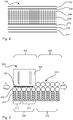
- Fig. 2 generally illustrates by way of example a packaging material 200 that can be used for forming the package 100.
- an outer coating 202 may be provided.
- the outer coating 202 may serve the purpose of avoiding that moisture of water is coming into contact with a printing layer 204 placed inside the outer coating 202.
- the printing layer 204 can comprise ink or any other material used for providing a print on the package 100.
- a first and a second paperboard layer 206, 208 can be provided inside the printing layer 204.
- the first and second paperboard layers 206, 208 provide robustness to the package 100.
- the first paperboard layer 206 may be bleached paperboard with or without claycoat.
- the second paperboard layer 208 may be bleached or unbleached paperboard.
- a lamination layer 210 made of plastic material can be provided.
- the lamination layer 210 can provide for that microorganisms are hindered from coming into contact with the product held inside the package 100.
- an Aluminum foil 212 can be provided inside the lamination layer 210.
- the Aluminum foil 212 can provide for that light, oxygen and odors are hindered from coming into contact with the product held inside the package 100, but also that flavors inside the package can be released from the package 100.
- the Aluminum foil 212 does however not exist in all types of packaging material. For instance, in the packaging material used for packages for chilled products, i.e. products that will be refrigerated, the Aluminum foil 212 is most often left out and replaced by a combination of lamination layers and paperboard layers.
- a first and a second internal coating 214, 216 made of e.g. plastics material, can be provided.
- a first and a second internal coating 214, 216 made of e.g. plastics material.
- One purpose with these are that the product is hindered from coming in direct contact with the Aluminum foil 212.
- Fig. 3 illustrates an example of a system 300 for transversal sealing of blanks, i.e. sleeve-shaped pieces 100 of packaging material 200 provided with longitudinal sealings, seen from above.
- the system 300 may form part of a packaging machine further comprising inter alia arrangements for feeding the blanks from a magazine to the system 300, arrangements for filling the blanks after the top or the bottom has been formed with product, and arrangements for folding the blanks into packages.
- the system 300 may be used both for forming the bottom of the package 100 by sealing together the first bottom sealing section 136 and the second bottom sealing section 138 or the top by sealing the first top sealing section 132 and the second top sealing section 134. It may be used for sleeve-shaped pieces 100 both with or without product, such as a food product, held inside. In other words, it may be used for closing a first end of the piece before filling with product, or it may be used for closing a second end after the piece has been filled with product.
- the system 300 comprises a heating station 302 for heating the piece 100 of packaging material 200 and a cooling station 304 for cooling down the piece of packaging material.
- a heating station 302 for heating the piece 100 of packaging material 200
- a cooling station 304 for cooling down the piece of packaging material.
- the heating station 302 comprises an ultra-sonic horn 306, or other equivalent device for producing ultrasonic waves, and a first group 308 of anvil elements.
- the first group 308 of anvil elements 308 may in turn comprise a first set and a second set 310, 312 of anvil elements.
- An overall aim of the first group 308 is to provide for that the piece 100 of packaging material is placed close to the ultra-sonic horn 306 such that the plastic layers 210, 212, 214 are subjected to heat such that in turn these melt.
- the first and second set 310, 312 may be adjusted such that higher pressure is applied in a first stage by the first set 310 compared to in a second stage by the second set 312.
- the piece (100) of packaging material is continuously fed through the heating station during the sealing.
- the anvil elements may comprise springs 314, such as compression springs, and anvil wheels 315 connected to the springs 314.
- the cooling station 304 comprises a second group 316 of anvil elements and cooling wheels 318.
- the cooling wheels 318 in combination with the second group 316 of anvil elements provide for that a first section, e.g. the first top sealing section 132 or the first bottom sealing section 136, is held close to a second section, e.g. the first bottom sealing section 134 or the second bottom sealing section 138, and due to that no heat is added and that the cooling wheels 318 as well as the second group of anvil elements 316 may be made of heat conductive material, such as stainless steel, heat will be transferred from the piece 100.
- the sleeve-shaped piece 100 comprises the longitudinal sealing, a width of the piece will not be the same over a whole range of the piece.
- three layers of packaging material will be provided an in other areas only two layers of packaging material will be provided resulting in different widths.
- the anvil wheels 315 with a diameter from 5 to 50 mm can be used.
- Fig. 4 illustrates another example of a system 400 for transversal sealing of blanks.
- the system 400 is in many aspects similar to the system 300 illustrated in fig. 3 .
- a difference between the two is however that instead of having one ultra-sonic horn 306 and one first group 308 of anvil elements, these have been duplicated in the system 400 illustrated in fig. 4 .
- a heating station 402 of the system 400 may add more heat to the piece 100 compared to the system 300 illustrated in fig. 3 .
- the system 300, 400 By having a modular approach like this for setting up the heating station 302, 402 as well as the cooling station 304, 404 it is made possible to adapt the system 300, 400 to different packaging materials requiring more or less heat and/or to different feeding speeds resulting in that more or less time is provided for providing heat.
- the sealing is performed in a continuous way and the packaging material is in constant movement during the sealing.
- the system 400 can be adapted by choosing anvil wheels 315 of different diameters.
- the anvil wheels 315 can be adapted as illustrated in fig. 5a and 5b.
- Fig. 5a illustrates an adapted anvil wheel 500a having a contact surface 502a.
- the contact surface 502a comprises a first segment 504a of a first segment type and a second segment 506a of a second segment type.
- the first segment 504a can be a cut out.
- this first anvil wheel 504a By aligning this first anvil wheel 504a with a geometry of the piece 100 this first segment 504a may be arranged to face the longitudinal sealing of the piece.
- a positive effect of this is that the cut out can compensate for that the longitudinal sealing comprises three layers of packaging material instead of two. By doing so, a risk of breaking the packaging material can be reduced.
- Fig. 5b illustrates another embodiment of the adapted anvil wheel 500b.
- the first segment 504b of the adapted anvil wheel 500b illustrated in fig. 5b is different from the first segment 504a of the adapted anvil wheel 500a illustrated in fig. 5a .
- the first segment 504b illustrated in fig. 5b is a cut out in part. In order to make sure that pressure is only applied via a mid-portion in the first segment 504b, two side sections on each side of the mid-portion have been removed.
- Fig. 6 illustrates a flowchart of a method 600 for sealing together the first section 132, 136 and the second section 134, 138 of the piece 100 of packaging material 200.
- a first step 602 the piece 100 is arranged such that the first and second section lie against each other.
- the at least one plastic layer 210, 212, 214 can be melted by subjecting the piece to ultra-sonic waves.
- the piece 100 is cooled down such that the at least one plastic layer 210, 212, 214 is solidified, and as an effect the sealing is formed.
- the system 400 may be modular. To provide for that the system 400 in fig. 4 , and also the system 300 illustrated in fig. 3 , can be efficiently set up, an anvil assembly 700 as illustrated in fig. 7 may be used.
- the anvil assembly comprises a group of anvil elements, which may be the first group of anvil elements 308 used in combination with the ultra-sonic horn 306 or the second group of anvil elements 316 used in combination with the cooling wheels 318 as illustrated in fig. 3 .
- the group of anvil elements 308, 316 may be attached to a mounting device 702 arranged for holding the group of anvil elements. By having the group of anvil elements attached to the mounting device 702 this can be easily mounted or demounted in the packaging machine such that for instance service interruptions can be shortened.
- a corresponding system may be described as:
Landscapes
- Engineering & Computer Science (AREA)
- Mechanical Engineering (AREA)
- Chemical & Material Sciences (AREA)
- Composite Materials (AREA)
- Physics & Mathematics (AREA)
- Thermal Sciences (AREA)
- Package Closures (AREA)
Abstract
Description
- The invention relates to packaging technology. More particularly, it relates to ultra-sonic sealing technology, such as a method for sealing together a first section and a second section of a piece of packaging material, a system for sealing and an anvil assembly.
- Within the field of packaging technology there is a number of different technologies available for sealing packaging material such that packages can be formed. A well-known technology used for sealing together packages is so-called ultra-sonic sealing. The general principle of this technology is that a sonotrode, also referred to as an ultra-sonic horn, is producing ultra-sonic waves, which results in that part of the packaging material melts. At the same time as heat is generated, two sections of the packaging material are pressed towards one another such that these attach to each other.
- Ultra-sonic sealing is commonly used within the packaging industry. Within the liquid food packaging industry, the technology is commonly used for producing packages for holding chilled products, that is, products to be held refrigerated and not in room temperature, such as pasteurized milk. One reason for that the ultra-sonic sealing technology is commonly used for packages for chilled products is that these packages, due to that they are placed in a refrigerator, do not need an Aluminum layer. An effect of not having an Aluminum layer is that technologies, such as induction heat sealing, which is requiring a conductive layer in the packaging material, cannot be used. Another effect of not having the Aluminum layer is that the environmental impact of the packages can be reduced.
- An anvil is used to provide for that the packaging material is positioned in relation to the sonotrode such that proper sealing can be achieved. As is disclosed in patent document
DE20216532 , the anvil may comprise a number of sections that are connected to compression springs. Also patent documentJP9278022 - Even though the prior art discloses ways to design the anvil such that an ultra-sonic sealing system may be adapted to for instance different packaging material thicknesses, there is still a need to further improve the ultra-sonic sealing system such that ultra-sonic sealings can be achieved in a more reliable, cost efficient and time efficient manner.
- It is an object of the invention to at least partly overcome one or more of the above-identified limitations of the prior art. In particular, it is an object to provide an improved method and system for ultra-sonic sealing from a cost as well as a quality perspective.
- According to a first aspect it is provided a method for sealing together a first section and a second section of a piece of packaging material. The method comprises
arranging the piece of packaging material such that the first and second section lie against each other,
melting at least one plastic layer in the first and second section by feeding the piece of packaging material through a heating station, wherein the heating station comprises at least one ultra-sonic horn placed on a first side of the piece and a first group of anvil elements placed on a second side of the piece, wherein the first side is opposite to the second side, wherein the first group of anvil elements is fixedly positioned with respect to the at least one ultra-sonic horn, and
cooling down the piece of packaging material such that the at least one plastic layer is solidified. - An advantage of having the first group fixedly positioned with respect to the at least one ultra-sonic horn, and thereby instead of having the anvil elements being moved having the piece being moved, provides for that a speed of the sealing may be increased. The piece of packaging material is continuously fed through the heating station. A continuous ultra-sonic seal is provided.
- Further, an advantage of having the anvil elements provided with the anvil heads is that the pressure P exerted onto the piece is provided by using a plurality of elements. By doing so, a risk that part of the piece is not provided with the pressure P, and as an effect that an insufficient sealing is provided, can be lowered. This especially holds true if the piece comprises a three-layer section, e.g. a longitudinal sealing, and two-layer sections.
- Having the plurality of elements also increases a possibility to fine tune the first group of anvil elements such that the pressure P exerted onto the piece is adapted such that sufficient sealing can be achieved.
- In addition, having the plurality of elements improves a redundancy of the heating station. For instance, even though one of the plurality of elements fails to exert pressure onto the piece, a remainder of the elements may provide sufficient pressure for achieving sufficient sealing.
- Further, the step of cooling down the piece may comprise feeding the piece through a cooling station, wherein the cooling station comprises cooling elements, such as cooling wheels, placed on the first side of the piece of packaging material and a second group of anvil elements placed on the second side of the piece of packaging material. The piece is continuously fed through the cooling station.
- The piece of packaging material may be a carton blank, and the first and second section may be a first and a second top sealing section of the carton blank or a first and a second bottom sealing section of the carton blank.
- The at least one ultra-sonic horn and the first group of anvil elements may be placed in a horizontal plane.
- At least part of the anvil elements may be attached to springs, such as compression springs.
- The anvil elements may be anvil wheels.
- At least one of the anvil wheels may be provided with a contact surface comprising at least one first segment of a first segment type and at least one second segment of a second segment type, wherein the first segment type is different from the second segment type.
- An advantage with having one or several of the anvil wheels provided with different segment types is that by aligning the anvil wheels with a geometry of the piece different pressure profiles may be applied to different parts of the piece. For instance, the first segment may interact with the three-layer section and the second segment may interact with the two-layer section.
- A diameter of the anvil wheels of the first group may be in the range of 5 to 50 mm.
- An advantage of having the anvil wheels in this range is that they can provide for that pressure for achieving reliable sealing can be applied also in intersection areas between the two-layer section and the three-layer section.
- According to a second aspect it is provided a system for sealing together a first section and a second section of a piece of packaging material, said system comprising
at least one heating station comprising at least one ultra-sonic horn placed on a first side of the piece and a first group of anvil elements placed on a second side of the piece, wherein the first side is opposite to the second side, wherein the first group of anvil elements is fixedly positioned with respect to the at least one ultra-sonic horn, and
a cooling station for cooling down the piece of packaging material such that the at least one plastic layer is solidified. - The cooling station may comprise cooling elements, such as cooling wheels, placed on the first side of the piece of packaging material and a second group of anvil elements placed on the second side of the piece of packaging material.
- The piece of packaging material may be a carton blank, and the first and second section may be a first and a second top sealing section of the carton blank or a first and a second bottom sealing section of the carton blank.
- The anvil elements may be anvil wheels.
- At least one of the anvil wheels may be provided with a contact surface comprising at least one first segment of a first segment type and at least one second segment of a second segment type, wherein the first segment type is different from the second segment type.
- A diameter of the anvil wheels of the first group may be in the range of 5 to 50 mm.
- According to a third aspect it is provided an anvil assembly comprising a group of anvil elements, wherein each anvil element comprises an anvil wheel, configured to be in contact with the piece, and a spring, such as a compression spring, wherein the anvil wheel is connected to the spring, and a mounting device for holding the group of anvil elements, wherein the springs of the anvil elements are connected to the mounting device.
- Even though not explicitly stated for each of the aspects, it is to be understood that the advantages presented with respect to one of the aspects also hold true for the other aspects.
- Embodiments will now be described, by way of example, with reference to the accompanying schematic drawings, in which
-
Fig. 1 a generally illustrates a perspective view of a package. -
Fig. 1b generally illustrates a piece of packaging material before being folded into the package illustrated infig. 1a . -
Fig. 2 illustrates a cross-sectional view of the packaging material. -
Fig. 3 illustrates by way of example a system for transversal sealing of blanks. -
Fig. 4 illustrates by way of example another system for transversal sealing of blanks. -
Fig. 5a and 5b illustrate examples of adoption of the anvil wheels. -
Fig 6 illustrates a flow chart of a method for sealing together a first and a second section of a piece of packaging material. -
Fig. 7 illustrates by way of example an anvil assembly. -
Fig. 1a generally illustrates an example of acarton package 100 made from a piece of package material illustrated infig. 1b . Thecarton package 100 comprises a number of panels divided from each other by weakening lines. The weakening lines provide for that the piece of packaging material can be reliably and efficiently folded into thepackage 100 by a packaging machine, also known as a filling machine. - In this example, the
package 100 comprises a firstrear panel 102, aleft panel 104, afront panel 106, aright panel 108 and a secondrear panel 110, which together form a sleeve-shaped main body of thepackage 100. The first and secondrear panel rear panel 110, that is placed inside a peripheral part of the firstrear panel 102, can be protected by a plastic strip, sometimes referred to as a longitudinal sealing strip. - Further, the
package 100 comprises a first toprear panel 112, a left cornertop panel 114, a topfront panel 116, aright corner panel 118 and a second toprear panel 120, which together form a top of thepackage 100. In a similar manner as the first and secondrear panel top panels package 100, the first and second reartop panels front panel 116, two sections of the left cornertop panel 114 are attached to each other, and two sections of the rightcorner top panel 118 are attached to each other. This is provided by a transversal sealing made in the packaging machine after the package is filled with the product. - The
package 100 also comprises a first bottomrear panel 122, a left cornerbottom panel 124, a bottomfront panel 126, a rightcorner bottom panel 128 and a second bottomrear panel 130, which together form a bottom of the package. In a similar manner as the first and secondrear panel rear panels package 100 and thereby form the bottom, the first and second bottomrear panels front panel 126, two sections of the left cornerbottom panel 124 are attached to each other, and two sections of the rightcorner bottom panel 128 are attached to each other. - In case the
package 100 is produced in a roll-fed packaging machine, a number of pieces of packaging material is provided after one another on a reel of packaging material. By having the pieces of packaging material arranged in this way a transversal sealing forming the bottom can be made at the same time as a transversal sealing forming the top of a subsequent package is made. After having made the transversal sealings, the packages are separated from each other by cutting them apart in a section between the transversal sealings. - To form the transversal sealing, a first
top sealing section 134 and a secondtop sealing section 132 as well as a firstbottom sealing section 136 and a secondtop sealing section 138 can be provided. After having made the transversal sealing, the packaging material can be separated such that the firsttop sealing section 132 and the secondtop sealing section 134 form an upper part of the top of thepackage 100, and in the firstbottom sealing section 136 and the secondbottom sealing section 138 form a lower part of the bottom of thepackage 100. To form the longitudinal sealing, alongitudinal sealing section 140 can be used. - In case the package is produced in a blanks-fed packaging machine, the longitudinal sealing is provided beforehand, that is, the first
rear panel 102 is attached to the secondrear panel 110 via thelongitudinal section 140, such that a sleeve-shaped piece of packaging material is provided. In addition, the separation, also referred to as cutting, is not made in the blanks-fed packaging machine, but is made when producing blanks to be fed into the blanks-fed packaging machine. -
Fig. 2 generally illustrates by way of example apackaging material 200 that can be used for forming thepackage 100. - Facing the surrounding space, an
outer coating 202 may be provided. Theouter coating 202 may serve the purpose of avoiding that moisture of water is coming into contact with aprinting layer 204 placed inside theouter coating 202. Theprinting layer 204 can comprise ink or any other material used for providing a print on thepackage 100. - Inside the
printing layer 204, a first and asecond paperboard layer package 100. Thefirst paperboard layer 206 may be bleached paperboard with or without claycoat. Thesecond paperboard layer 208 may be bleached or unbleached paperboard. - Next a
lamination layer 210 made of plastic material can be provided. Thelamination layer 210 can provide for that microorganisms are hindered from coming into contact with the product held inside thepackage 100. - Inside the
lamination layer 210, anAluminum foil 212 can be provided. TheAluminum foil 212 can provide for that light, oxygen and odors are hindered from coming into contact with the product held inside thepackage 100, but also that flavors inside the package can be released from thepackage 100. TheAluminum foil 212 does however not exist in all types of packaging material. For instance, in the packaging material used for packages for chilled products, i.e. products that will be refrigerated, theAluminum foil 212 is most often left out and replaced by a combination of lamination layers and paperboard layers. - Closest to the product held inside the
package 100, a first and a secondinternal coating 214, 216, made of e.g. plastics material, can be provided. One purpose with these are that the product is hindered from coming in direct contact with theAluminum foil 212. -
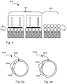
Fig. 3 illustrates an example of asystem 300 for transversal sealing of blanks, i.e. sleeve-shapedpieces 100 ofpackaging material 200 provided with longitudinal sealings, seen from above. Thesystem 300 may form part of a packaging machine further comprising inter alia arrangements for feeding the blanks from a magazine to thesystem 300, arrangements for filling the blanks after the top or the bottom has been formed with product, and arrangements for folding the blanks into packages. - The
system 300 may be used both for forming the bottom of thepackage 100 by sealing together the firstbottom sealing section 136 and the secondbottom sealing section 138 or the top by sealing the firsttop sealing section 132 and the secondtop sealing section 134. It may be used for sleeve-shapedpieces 100 both with or without product, such as a food product, held inside. In other words, it may be used for closing a first end of the piece before filling with product, or it may be used for closing a second end after the piece has been filled with product. - On a general level, the
system 300 comprises aheating station 302 for heating thepiece 100 ofpackaging material 200 and acooling station 304 for cooling down the piece of packaging material. When heating thepiece 100 in theheating station 302 at least one of theplastic layers plastic layers - The
heating station 302 comprises anultra-sonic horn 306, or other equivalent device for producing ultrasonic waves, and afirst group 308 of anvil elements. Thefirst group 308 ofanvil elements 308 may in turn comprise a first set and asecond set first group 308 is to provide for that thepiece 100 of packaging material is placed close to theultra-sonic horn 306 such that theplastic layers second set first set 310 is placed before thesecond set 312 in a direction of movement D of thepiece 100, it is made possible to apply different pressures at different stages of theheating station 302. For instance, to provide for that the melting of the plastic layers is made in a controlled manner, it has been found that the first andsecond set first set 310 compared to in a second stage by thesecond set 312. By applying the higher pressure in the first stage compared to the second stage a risk of not having the melting of the plastic layers initiated can be reduced, and also be applying less pressure in the second stage a risk of over-melting the at least one plastic layers can be reduced. The piece (100) of packaging material is continuously fed through the heating station during the sealing. The anvil elements may comprisesprings 314, such as compression springs, andanvil wheels 315 connected to thesprings 314. - After the
heating station 302 thepiece 100 is continuously fed by the anvil elements to thecooling station 304. Thecooling station 304 comprises asecond group 316 of anvil elements and coolingwheels 318. When feeding thepiece 100 through thecooling station 304, the coolingwheels 318 in combination with thesecond group 316 of anvil elements provide for that a first section, e.g. the firsttop sealing section 132 or the firstbottom sealing section 136, is held close to a second section, e.g. the firstbottom sealing section 134 or the secondbottom sealing section 138, and due to that no heat is added and that the coolingwheels 318 as well as the second group ofanvil elements 316 may be made of heat conductive material, such as stainless steel, heat will be transferred from thepiece 100. - Since the sleeve-shaped
piece 100 comprises the longitudinal sealing, a width of the piece will not be the same over a whole range of the piece. In an area of the longitudinal sealing three layers of packaging material will be provided an in other areas only two layers of packaging material will be provided resulting in different widths. To provide for that sufficient pressure is provided throughout the whole range, including intersection areas between two-layer packaging material areas and three-layer packaging material areas, it has been found that theanvil wheels 315 with a diameter from 5 to 50 mm can be used. -
Fig. 4 illustrates another example of asystem 400 for transversal sealing of blanks. Thesystem 400 is in many aspects similar to thesystem 300 illustrated infig. 3 . A difference between the two is however that instead of having oneultra-sonic horn 306 and onefirst group 308 of anvil elements, these have been duplicated in thesystem 400 illustrated infig. 4 . By doing so, aheating station 402 of thesystem 400 may add more heat to thepiece 100 compared to thesystem 300 illustrated infig. 3 . By having a modular approach like this for setting up theheating station cooling station system system 400 can be adapted by choosinganvil wheels 315 of different diameters. - In addition to choosing the diameter of the
anvil wheels 315 such that sufficient pressure can be applied also in the area of the longitudinal sealing, theanvil wheels 315 can be adapted as illustrated infig. 5a and 5b. Fig. 5a illustrates an adaptedanvil wheel 500a having acontact surface 502a. Thecontact surface 502a comprises afirst segment 504a of a first segment type and asecond segment 506a of a second segment type. As illustrated, thefirst segment 504a can be a cut out. By aligning thisfirst anvil wheel 504a with a geometry of thepiece 100 thisfirst segment 504a may be arranged to face the longitudinal sealing of the piece. A positive effect of this is that the cut out can compensate for that the longitudinal sealing comprises three layers of packaging material instead of two. By doing so, a risk of breaking the packaging material can be reduced. -
Fig. 5b illustrates another embodiment of the adaptedanvil wheel 500b. Thefirst segment 504b of the adaptedanvil wheel 500b illustrated infig. 5b is different from thefirst segment 504a of the adaptedanvil wheel 500a illustrated infig. 5a . Instead of being a full cut out, thefirst segment 504b illustrated infig. 5b is a cut out in part. In order to make sure that pressure is only applied via a mid-portion in thefirst segment 504b, two side sections on each side of the mid-portion have been removed. -
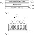
Fig. 6 illustrates a flowchart of amethod 600 for sealing together thefirst section second section piece 100 ofpackaging material 200. In afirst step 602, thepiece 100 is arranged such that the first and second section lie against each other. In asecond step 604, the at least oneplastic layer third step 606, thepiece 100 is cooled down such that the at least oneplastic layer - As illustrated in
fig. 4 , thesystem 400 may be modular. To provide for that thesystem 400 infig. 4 , and also thesystem 300 illustrated infig. 3 , can be efficiently set up, ananvil assembly 700 as illustrated infig. 7 may be used. The anvil assembly comprises a group of anvil elements, which may be the first group ofanvil elements 308 used in combination with theultra-sonic horn 306 or the second group ofanvil elements 316 used in combination with the coolingwheels 318 as illustrated infig. 3 . The group ofanvil elements device 702 arranged for holding the group of anvil elements. By having the group of anvil elements attached to the mountingdevice 702 this can be easily mounted or demounted in the packaging machine such that for instance service interruptions can be shortened. - As described above, having higher pressure in the first stage than in the second stage comes with a number of advantages. An example of a method using this conceptual idea may be described as:
- A method for sealing together a
first section second section piece 100 ofpackaging material 200, said method comprising - arranging the
piece 100 of packaging material such that the first 132,136 and second section 134,138 lie against each other, - melting at least one
plastic layer second section piece 100 of packaging material through aheating station 302, - wherein the
heating station 302 comprises at least one ultra-sonic horn (306) placed on a first side of thepiece 100 and a first group (308) of anvil elements placed on a second side of thepiece 100, wherein the first side is opposite to the second side, - wherein the
first group 308 of anvil elements comprises a first and asecond set first set 310 of anvil elements is placed before thesecond set 312 of anvil elements in a direction of movement D of thepiece 100, - wherein the
first set 310 of anvil elements exerts a first pressure P1 onto thepiece 100 and thesecond set 312 exerts a second pressure P2 onto the piece (100), wherein the first pressure P1 is greater than the second pressure P2, and - cooling 606 down the
piece 100 of packaging material such that the at least oneplastic layer - A corresponding system may be described as:
- A
system 300 for sealing together afirst section second section piece 100 ofpackaging material 200, said system comprising - at least one
heating station 302 comprising at least oneultra-sonic horn 306 placed on a first side of thepiece 100 and afirst group 308 of anvil elements placed on a second side of thepiece 100, wherein the first side is opposite to the second side, - wherein the
first group 308 of anvil elements comprises a first and asecond set first set 310 of anvil elements is placed before thesecond set 312 of anvil elements in a direction of movement D of thepiece 100, - wherein the
first set 310 of anvil elements exerts a first pressure (P1) onto thepiece 100 and thesecond set 312 exerts a second pressure P2 onto thepiece 100, wherein the first pressure P1 is greater than the second pressure P2, and - a
cooling station 304 for cooling down thepiece 100 of packaging material such that the at least oneplastic layer - From the description above follows that, although various embodiments of the invention have been described and shown, the invention is not restricted thereto, but may also be embodied in other ways within the scope of the subject-matter defined in the following claims.
Claims (15)
- A method (600) for sealing together a first section (132, 136) and a second section (134, 138) of a piece (100) of packaging material (200), said method comprising
arranging (602) the piece (100) of packaging material such that the first (132,136) and second section (134,138) lie against each other,
melting (604) at least one plastic layer (210, 214, 216) in the first (132, 136) and second section (134, 138) by feeding the piece (100) of packaging material through a heating station (302), wherein the heating station (302) comprises at least one ultra-sonic horn (306) placed on a first side of the piece (100) and a first group (308) of anvil elements placed on a second side of the piece (100), wherein the first side is opposite to the second side, wherein the first group (308) of anvil elements is fixedly positioned with respect to the at least one ultra-sonic horn (306), and
cooling (606) down the piece (100) of packaging material such that the at least one plastic layer (210, 214, 216) is solidified. - The method according to claim 1, wherein the step of cooling (606) down the piece (100) comprises feeding the piece (100) through a cooling station (304), wherein the cooling station (304) comprises cooling elements (318), such as cooling wheels, placed on the first side of the piece (100) of packaging material and a second group (316) of anvil elements placed on the second side of the piece (100) of packaging material.
- The method according to any one of the preceding claims, wherein the piece (100) of packaging material is a carton blank, and the first and second section (132, 136, 134, 138) is a first and a second top sealing section (132,134) of the carton blank or a first and a second bottom sealing section (136, 138) of the carton blank.
- The method according to claim 3, wherein the at least one ultra-sonic horn (306) and the first group (308) of anvil elements are placed in a horizontal plane.
- The method according to any one of the preceding claims, wherein at least part of the anvil elements are attached to springs (314), such as compression springs.
- The method according to any one of the preceding claims, wherein the anvil elements are anvil wheels.
- The method according to claim 6, wherein at least one of the anvil wheels (500a, 500b) are provided with a contact surface (502a, 502b) comprising at least one first segment (504a, 504b) of a first segment type and at least one second segment (506a, 506b) of a second segment type, wherein the first segment type is different from the second segment type.
- The method according to claim 6 or 7, wherein a diameter of the anvil wheels of the first group (308) is in the range of 5 to 50 mm.
- A system (300) for sealing together a first section (132, 136) and a second section (134, 138) of a piece (100) of packaging material (200), said system comprising
at least one heating station (302) comprising at least one ultra-sonic horn (306) placed on a first side of the piece (100) and a first group (308) of anvil elements placed on a second side of the piece (100), wherein the first side is opposite to the second side, wherein the first group (308) of anvil elements is fixedly positioned with respect to the at least one ultra-sonic horn (306), and
a cooling station (304) for cooling down the piece (100) of packaging material such that the at least one plastic layer (212, 214, 216) is solidified. - The system according to claim 9, wherein the cooling station (304) comprises cooling elements (318), such as cooling wheels, placed on the first side of the piece (100) of packaging material and a second group (316) of anvil elements placed on the second side of the piece (100) of packaging material.
- The system according to claim 9 or 10, wherein the piece (100) of packaging material is a carton blank, and the first and second section (132, 136, 134, 138) is a first and a second top sealing section (132,134) of the carton blank or a first and a second bottom sealing section (136, 138) of the carton blank.
- The system according to any one of the claims 9 to 11, wherein the anvil elements are anvil wheels.
- The system according to claim 12, wherein at least one of the anvil wheels (500a, 500b) are provided with a contact surface (502a, 502b) comprising at least one first segment (504a, 504b) of a first segment type and at least one second segment (506a, 506b) of a second segment type, wherein the first segment type is different from the second segment type.
- The system according to claim 12 or 13, wherein a diameter of the anvil wheels of the first group (308) is in the range of 5 to 50 mm.
- An anvil assembly (700) comprising
a group of anvil elements (308, 316), wherein each anvil element comprises an anvil wheel (315), configured to be in contact with the piece (100), and a spring (314), such as a compression spring, wherein the anvil wheel is connected to the spring (314),
a mounting device (702) for holding the group of anvil elements (308, 316), wherein the springs (314) of the anvil elements are connected to the mounting device.
Applications Claiming Priority (1)
| Application Number | Priority Date | Filing Date | Title |
|---|---|---|---|
| EP18177294 | 2018-06-12 |
Publications (2)
| Publication Number | Publication Date |
|---|---|
| EP3581369A1 true EP3581369A1 (en) | 2019-12-18 |
| EP3581369B1 EP3581369B1 (en) | 2022-01-26 |
Family
ID=62620757
Family Applications (1)
| Application Number | Title | Priority Date | Filing Date |
|---|---|---|---|
| EP19178436.2A Active EP3581369B1 (en) | 2018-06-12 | 2019-06-05 | A method for sealing together a first section and a second section of a packaging material, a system for sealing |
Country Status (4)
| Country | Link |
|---|---|
| EP (1) | EP3581369B1 (en) |
| CN (2) | CN211076613U (en) |
| ES (1) | ES2911286T3 (en) |
| WO (1) | WO2019238498A1 (en) |
Families Citing this family (1)
| Publication number | Priority date | Publication date | Assignee | Title |
|---|---|---|---|---|
| US12570873B2 (en) | 2021-06-09 | 2026-03-10 | Upm Raflatac Oy | Glassine paper material for wrapping self-adhesive note pads |
Citations (5)
| Publication number | Priority date | Publication date | Assignee | Title |
|---|---|---|---|---|
| FR2136875A2 (en) * | 1971-05-07 | 1972-12-29 | Chupin Clement Papeterie | |
| JPS52125540A (en) * | 1976-04-15 | 1977-10-21 | Seidensha Electronics | Ultrasonic continuous solvent welding method of plastic film and cloth etc |
| FR2628030A1 (en) * | 1988-03-07 | 1989-09-08 | Macse Sarl | Appts. for continuous ultrasonic welding of ends of sacks - with driven rollers to support weld zone as it passes sonotrode beam |
| JPH09278022A (en) * | 1996-04-12 | 1997-10-28 | Gunze Ltd | Ultrasonic sealing device |
| DE20216532U1 (en) | 2002-10-26 | 2003-02-20 | Haver & Boecker, 59302 Oelde | Ultrasonic welding assembly, for welding thin and flexible packaging materials, has an anvil with profiled sections moved by a drive across the direction of sonotrode movement, by less than the anvil width |
Family Cites Families (6)
| Publication number | Priority date | Publication date | Assignee | Title |
|---|---|---|---|---|
| DE19505298A1 (en) * | 1995-02-16 | 1996-08-22 | Ips Int Packaging Syst | Ultrasonic sealing |
| WO2006029835A1 (en) * | 2004-09-14 | 2006-03-23 | Jentschmann Ag Zürich | A welding device |
| AT507384B1 (en) * | 2008-09-18 | 2011-07-15 | Westwind Verpackungen Gmbh | CLOSING DEVICE FOR CLOSING PREFERABLY BAGGED PACKAGING UNITS |
| DE102010005847B4 (en) * | 2010-01-26 | 2019-09-26 | Sig Technology Ag | A method of manufacturing a food-free aluminum-free laminar composite food container having a multiple inner layer by hot folding |
| JP2012236621A (en) * | 2011-05-11 | 2012-12-06 | Ishida Co Ltd | Form-fill-seal machine |
| CN202807177U (en) * | 2012-07-25 | 2013-03-20 | 长沙琦清机械设备有限公司 | Ultrasonic-based packaging film heat-sealing device |
-
2019
- 2019-06-05 ES ES19178436T patent/ES2911286T3/en active Active
- 2019-06-05 EP EP19178436.2A patent/EP3581369B1/en active Active
- 2019-06-05 WO PCT/EP2019/064664 patent/WO2019238498A1/en not_active Ceased
- 2019-06-10 CN CN201920861561.9U patent/CN211076613U/en active Active
- 2019-06-10 CN CN201910497288.0A patent/CN110589111B/en active Active
Patent Citations (5)
| Publication number | Priority date | Publication date | Assignee | Title |
|---|---|---|---|---|
| FR2136875A2 (en) * | 1971-05-07 | 1972-12-29 | Chupin Clement Papeterie | |
| JPS52125540A (en) * | 1976-04-15 | 1977-10-21 | Seidensha Electronics | Ultrasonic continuous solvent welding method of plastic film and cloth etc |
| FR2628030A1 (en) * | 1988-03-07 | 1989-09-08 | Macse Sarl | Appts. for continuous ultrasonic welding of ends of sacks - with driven rollers to support weld zone as it passes sonotrode beam |
| JPH09278022A (en) * | 1996-04-12 | 1997-10-28 | Gunze Ltd | Ultrasonic sealing device |
| DE20216532U1 (en) | 2002-10-26 | 2003-02-20 | Haver & Boecker, 59302 Oelde | Ultrasonic welding assembly, for welding thin and flexible packaging materials, has an anvil with profiled sections moved by a drive across the direction of sonotrode movement, by less than the anvil width |
Also Published As
| Publication number | Publication date |
|---|---|
| CN110589111B (en) | 2022-12-27 |
| WO2019238498A1 (en) | 2019-12-19 |
| CN211076613U (en) | 2020-07-24 |
| ES2911286T3 (en) | 2022-05-18 |
| CN110589111A (en) | 2019-12-20 |
| EP3581369B1 (en) | 2022-01-26 |
Similar Documents
| Publication | Publication Date | Title |
|---|---|---|
| US20050209075A1 (en) | Method and apparatus for forming corrugated board carton blanks | |
| US20190202587A1 (en) | Anvil and ultrasonic sealing apparatus | |
| US4606784A (en) | Method and an arrangement for the folding and sealing of the longitudinal edge of a material web | |
| US11518076B2 (en) | Molding apparatus configured to injection mold an opening device on a sheet of packaging material | |
| EP3581369B1 (en) | A method for sealing together a first section and a second section of a packaging material, a system for sealing | |
| US7231752B2 (en) | Method and device for packing products in films and film-packed product | |
| US20020157349A1 (en) | High-frequency heat-sealing apparatus | |
| EP3581368B1 (en) | A method for sealing together a first section and a second section of a piece of packaging material, an anvil assembly and a system comprising such assembly | |
| EP3360811B1 (en) | A packaging material and a method for providing a packaging material | |
| US20240158128A1 (en) | Composite packaging material sheet, method for forming a composite packaging material sheet, composite package and method for forming a composite package | |
| US20040259709A1 (en) | Packaging sheet material for packaging pourable food products | |
| US12459691B2 (en) | Method for transversally sealing a tube of packaging material using an ultrasonic sealing device, an anvil and an ultra-sonic sealing device | |
| JP2025143448A (en) | Inductors and ultrasonic horns | |
| US20250250057A1 (en) | Packaging blank and package | |
| JP2006182364A (en) | Machining tool for packaging body connecting belt, machining apparatus for packaging body connecting belt, and packaging body manufacturing system and method | |
| JP2018520069A (en) | Assembly and method for processing package containers | |
| EP4261018B1 (en) | A transversal sealing system and a method for transversally sealing a tube of packaging material | |
| EP3718915A1 (en) | A crease tool and a system and method for creasing a packaging material | |
| EP4491524B1 (en) | Cap application device for a capping apparatus, capping apparatus for a packaging machine and packaging machine having a capping apparatus | |
| EP4269267A2 (en) | Packaging blank, method for molding a lid-spout assembly onto a packaging blank, lid spout assembly, package having a lid-spout assembly and method and apparatus for forming a packaging blank | |
| EP4592209A1 (en) | Opening device for a package and package | |
| EP4242117A1 (en) | Control method for a packaging machine and associated packaging machine | |
| EP4001149A1 (en) | Opening device for a package and package having an opening device | |
| WO2024160636A1 (en) | Package forming apparatus for a packaging machine and packaging machine for forming packages filled with a pourable product | |
| EP0144469A1 (en) | A joint on packing containers and a method for the manufacture of the same |
Legal Events
| Date | Code | Title | Description |
|---|---|---|---|
| PUAI | Public reference made under article 153(3) epc to a published international application that has entered the european phase |
Free format text: ORIGINAL CODE: 0009012 |
|
| STAA | Information on the status of an ep patent application or granted ep patent |
Free format text: STATUS: THE APPLICATION HAS BEEN PUBLISHED |
|
| AK | Designated contracting states |
Kind code of ref document: A1 Designated state(s): AL AT BE BG CH CY CZ DE DK EE ES FI FR GB GR HR HU IE IS IT LI LT LU LV MC MK MT NL NO PL PT RO RS SE SI SK SM TR |
|
| AX | Request for extension of the european patent |
Extension state: BA ME |
|
| STAA | Information on the status of an ep patent application or granted ep patent |
Free format text: STATUS: REQUEST FOR EXAMINATION WAS MADE |
|
| 17P | Request for examination filed |
Effective date: 20200618 |
|
| RBV | Designated contracting states (corrected) |
Designated state(s): AL AT BE BG CH CY CZ DE DK EE ES FI FR GB GR HR HU IE IS IT LI LT LU LV MC MK MT NL NO PL PT RO RS SE SI SK SM TR |
|
| STAA | Information on the status of an ep patent application or granted ep patent |
Free format text: STATUS: EXAMINATION IS IN PROGRESS |
|
| 17Q | First examination report despatched |
Effective date: 20210127 |
|
| GRAP | Despatch of communication of intention to grant a patent |
Free format text: ORIGINAL CODE: EPIDOSNIGR1 |
|
| STAA | Information on the status of an ep patent application or granted ep patent |
Free format text: STATUS: GRANT OF PATENT IS INTENDED |
|
| INTG | Intention to grant announced |
Effective date: 20210924 |
|
| GRAS | Grant fee paid |
Free format text: ORIGINAL CODE: EPIDOSNIGR3 |
|
| GRAA | (expected) grant |
Free format text: ORIGINAL CODE: 0009210 |
|
| STAA | Information on the status of an ep patent application or granted ep patent |
Free format text: STATUS: THE PATENT HAS BEEN GRANTED |
|
| AK | Designated contracting states |
Kind code of ref document: B1 Designated state(s): AL AT BE BG CH CY CZ DE DK EE ES FI FR GB GR HR HU IE IS IT LI LT LU LV MC MK MT NL NO PL PT RO RS SE SI SK SM TR |
|
| REG | Reference to a national code |
Ref country code: GB Ref legal event code: FG4D |
|
| REG | Reference to a national code |
Ref country code: CH Ref legal event code: EP |
|
| REG | Reference to a national code |
Ref country code: AT Ref legal event code: REF Ref document number: 1464933 Country of ref document: AT Kind code of ref document: T Effective date: 20220215 |
|
| REG | Reference to a national code |
Ref country code: IE Ref legal event code: FG4D |
|
| REG | Reference to a national code |
Ref country code: DE Ref legal event code: R096 Ref document number: 602019011152 Country of ref document: DE |
|
| REG | Reference to a national code |
Ref country code: ES Ref legal event code: FG2A Ref document number: 2911286 Country of ref document: ES Kind code of ref document: T3 Effective date: 20220518 |
|
| REG | Reference to a national code |
Ref country code: LT Ref legal event code: MG9D |
|
| REG | Reference to a national code |
Ref country code: NL Ref legal event code: MP Effective date: 20220126 |
|
| REG | Reference to a national code |
Ref country code: AT Ref legal event code: MK05 Ref document number: 1464933 Country of ref document: AT Kind code of ref document: T Effective date: 20220126 |
|
| PG25 | Lapsed in a contracting state [announced via postgrant information from national office to epo] |
Ref country code: NL Free format text: LAPSE BECAUSE OF FAILURE TO SUBMIT A TRANSLATION OF THE DESCRIPTION OR TO PAY THE FEE WITHIN THE PRESCRIBED TIME-LIMIT Effective date: 20220126 |
|
| PG25 | Lapsed in a contracting state [announced via postgrant information from national office to epo] |
Ref country code: SE Free format text: LAPSE BECAUSE OF FAILURE TO SUBMIT A TRANSLATION OF THE DESCRIPTION OR TO PAY THE FEE WITHIN THE PRESCRIBED TIME-LIMIT Effective date: 20220126 Ref country code: RS Free format text: LAPSE BECAUSE OF FAILURE TO SUBMIT A TRANSLATION OF THE DESCRIPTION OR TO PAY THE FEE WITHIN THE PRESCRIBED TIME-LIMIT Effective date: 20220126 Ref country code: PT Free format text: LAPSE BECAUSE OF FAILURE TO SUBMIT A TRANSLATION OF THE DESCRIPTION OR TO PAY THE FEE WITHIN THE PRESCRIBED TIME-LIMIT Effective date: 20220526 Ref country code: NO Free format text: LAPSE BECAUSE OF FAILURE TO SUBMIT A TRANSLATION OF THE DESCRIPTION OR TO PAY THE FEE WITHIN THE PRESCRIBED TIME-LIMIT Effective date: 20220426 Ref country code: LT Free format text: LAPSE BECAUSE OF FAILURE TO SUBMIT A TRANSLATION OF THE DESCRIPTION OR TO PAY THE FEE WITHIN THE PRESCRIBED TIME-LIMIT Effective date: 20220126 Ref country code: HR Free format text: LAPSE BECAUSE OF FAILURE TO SUBMIT A TRANSLATION OF THE DESCRIPTION OR TO PAY THE FEE WITHIN THE PRESCRIBED TIME-LIMIT Effective date: 20220126 Ref country code: BG Free format text: LAPSE BECAUSE OF FAILURE TO SUBMIT A TRANSLATION OF THE DESCRIPTION OR TO PAY THE FEE WITHIN THE PRESCRIBED TIME-LIMIT Effective date: 20220426 |
|
| PG25 | Lapsed in a contracting state [announced via postgrant information from national office to epo] |
Ref country code: PL Free format text: LAPSE BECAUSE OF FAILURE TO SUBMIT A TRANSLATION OF THE DESCRIPTION OR TO PAY THE FEE WITHIN THE PRESCRIBED TIME-LIMIT Effective date: 20220126 Ref country code: LV Free format text: LAPSE BECAUSE OF FAILURE TO SUBMIT A TRANSLATION OF THE DESCRIPTION OR TO PAY THE FEE WITHIN THE PRESCRIBED TIME-LIMIT Effective date: 20220126 Ref country code: GR Free format text: LAPSE BECAUSE OF FAILURE TO SUBMIT A TRANSLATION OF THE DESCRIPTION OR TO PAY THE FEE WITHIN THE PRESCRIBED TIME-LIMIT Effective date: 20220427 Ref country code: FI Free format text: LAPSE BECAUSE OF FAILURE TO SUBMIT A TRANSLATION OF THE DESCRIPTION OR TO PAY THE FEE WITHIN THE PRESCRIBED TIME-LIMIT Effective date: 20220126 Ref country code: AT Free format text: LAPSE BECAUSE OF FAILURE TO SUBMIT A TRANSLATION OF THE DESCRIPTION OR TO PAY THE FEE WITHIN THE PRESCRIBED TIME-LIMIT Effective date: 20220126 |
|
| PG25 | Lapsed in a contracting state [announced via postgrant information from national office to epo] |
Ref country code: IS Free format text: LAPSE BECAUSE OF FAILURE TO SUBMIT A TRANSLATION OF THE DESCRIPTION OR TO PAY THE FEE WITHIN THE PRESCRIBED TIME-LIMIT Effective date: 20220526 |
|
| REG | Reference to a national code |
Ref country code: DE Ref legal event code: R097 Ref document number: 602019011152 Country of ref document: DE |
|
| PG25 | Lapsed in a contracting state [announced via postgrant information from national office to epo] |
Ref country code: SM Free format text: LAPSE BECAUSE OF FAILURE TO SUBMIT A TRANSLATION OF THE DESCRIPTION OR TO PAY THE FEE WITHIN THE PRESCRIBED TIME-LIMIT Effective date: 20220126 Ref country code: SK Free format text: LAPSE BECAUSE OF FAILURE TO SUBMIT A TRANSLATION OF THE DESCRIPTION OR TO PAY THE FEE WITHIN THE PRESCRIBED TIME-LIMIT Effective date: 20220126 Ref country code: RO Free format text: LAPSE BECAUSE OF FAILURE TO SUBMIT A TRANSLATION OF THE DESCRIPTION OR TO PAY THE FEE WITHIN THE PRESCRIBED TIME-LIMIT Effective date: 20220126 Ref country code: EE Free format text: LAPSE BECAUSE OF FAILURE TO SUBMIT A TRANSLATION OF THE DESCRIPTION OR TO PAY THE FEE WITHIN THE PRESCRIBED TIME-LIMIT Effective date: 20220126 Ref country code: DK Free format text: LAPSE BECAUSE OF FAILURE TO SUBMIT A TRANSLATION OF THE DESCRIPTION OR TO PAY THE FEE WITHIN THE PRESCRIBED TIME-LIMIT Effective date: 20220126 Ref country code: CZ Free format text: LAPSE BECAUSE OF FAILURE TO SUBMIT A TRANSLATION OF THE DESCRIPTION OR TO PAY THE FEE WITHIN THE PRESCRIBED TIME-LIMIT Effective date: 20220126 |
|
| PG25 | Lapsed in a contracting state [announced via postgrant information from national office to epo] |
Ref country code: AL Free format text: LAPSE BECAUSE OF FAILURE TO SUBMIT A TRANSLATION OF THE DESCRIPTION OR TO PAY THE FEE WITHIN THE PRESCRIBED TIME-LIMIT Effective date: 20220126 |
|
| PLBE | No opposition filed within time limit |
Free format text: ORIGINAL CODE: 0009261 |
|
| STAA | Information on the status of an ep patent application or granted ep patent |
Free format text: STATUS: NO OPPOSITION FILED WITHIN TIME LIMIT |
|
| 26N | No opposition filed |
Effective date: 20221027 |
|
| PG25 | Lapsed in a contracting state [announced via postgrant information from national office to epo] |
Ref country code: MC Free format text: LAPSE BECAUSE OF FAILURE TO SUBMIT A TRANSLATION OF THE DESCRIPTION OR TO PAY THE FEE WITHIN THE PRESCRIBED TIME-LIMIT Effective date: 20220126 |
|
| REG | Reference to a national code |
Ref country code: CH Ref legal event code: PL |
|
| REG | Reference to a national code |
Ref country code: BE Ref legal event code: MM Effective date: 20220630 |
|
| PG25 | Lapsed in a contracting state [announced via postgrant information from national office to epo] |
Ref country code: SI Free format text: LAPSE BECAUSE OF FAILURE TO SUBMIT A TRANSLATION OF THE DESCRIPTION OR TO PAY THE FEE WITHIN THE PRESCRIBED TIME-LIMIT Effective date: 20220126 |
|
| PG25 | Lapsed in a contracting state [announced via postgrant information from national office to epo] |
Ref country code: LU Free format text: LAPSE BECAUSE OF NON-PAYMENT OF DUE FEES Effective date: 20220605 Ref country code: LI Free format text: LAPSE BECAUSE OF NON-PAYMENT OF DUE FEES Effective date: 20220630 Ref country code: IE Free format text: LAPSE BECAUSE OF NON-PAYMENT OF DUE FEES Effective date: 20220605 Ref country code: FR Free format text: LAPSE BECAUSE OF NON-PAYMENT OF DUE FEES Effective date: 20220630 Ref country code: CH Free format text: LAPSE BECAUSE OF NON-PAYMENT OF DUE FEES Effective date: 20220630 |
|
| PG25 | Lapsed in a contracting state [announced via postgrant information from national office to epo] |
Ref country code: BE Free format text: LAPSE BECAUSE OF NON-PAYMENT OF DUE FEES Effective date: 20220630 |
|
| P01 | Opt-out of the competence of the unified patent court (upc) registered |
Effective date: 20230426 |
|
| GBPC | Gb: european patent ceased through non-payment of renewal fee |
Effective date: 20230605 |
|
| PG25 | Lapsed in a contracting state [announced via postgrant information from national office to epo] |
Ref country code: MK Free format text: LAPSE BECAUSE OF FAILURE TO SUBMIT A TRANSLATION OF THE DESCRIPTION OR TO PAY THE FEE WITHIN THE PRESCRIBED TIME-LIMIT Effective date: 20220126 Ref country code: CY Free format text: LAPSE BECAUSE OF FAILURE TO SUBMIT A TRANSLATION OF THE DESCRIPTION OR TO PAY THE FEE WITHIN THE PRESCRIBED TIME-LIMIT Effective date: 20220126 Ref country code: GB Free format text: LAPSE BECAUSE OF NON-PAYMENT OF DUE FEES Effective date: 20230605 |
|
| PG25 | Lapsed in a contracting state [announced via postgrant information from national office to epo] |
Ref country code: HU Free format text: LAPSE BECAUSE OF FAILURE TO SUBMIT A TRANSLATION OF THE DESCRIPTION OR TO PAY THE FEE WITHIN THE PRESCRIBED TIME-LIMIT; INVALID AB INITIO Effective date: 20190605 |
|
| PG25 | Lapsed in a contracting state [announced via postgrant information from national office to epo] |
Ref country code: MT Free format text: LAPSE BECAUSE OF FAILURE TO SUBMIT A TRANSLATION OF THE DESCRIPTION OR TO PAY THE FEE WITHIN THE PRESCRIBED TIME-LIMIT Effective date: 20220126 |
|
| PGFP | Annual fee paid to national office [announced via postgrant information from national office to epo] |
Ref country code: DE Payment date: 20250626 Year of fee payment: 7 |
|
| PGFP | Annual fee paid to national office [announced via postgrant information from national office to epo] |
Ref country code: ES Payment date: 20250710 Year of fee payment: 7 |
|
| PGFP | Annual fee paid to national office [announced via postgrant information from national office to epo] |
Ref country code: IT Payment date: 20250623 Year of fee payment: 7 |
|
| PG25 | Lapsed in a contracting state [announced via postgrant information from national office to epo] |
Ref country code: TR Free format text: LAPSE BECAUSE OF FAILURE TO SUBMIT A TRANSLATION OF THE DESCRIPTION OR TO PAY THE FEE WITHIN THE PRESCRIBED TIME-LIMIT Effective date: 20220126 |