EP3581356A1 - Method and apparatus of modular punch forming plates for alignment of a stringer for a vehicle - Google Patents
Method and apparatus of modular punch forming plates for alignment of a stringer for a vehicle Download PDFInfo
- Publication number
- EP3581356A1 EP3581356A1 EP19164961.5A EP19164961A EP3581356A1 EP 3581356 A1 EP3581356 A1 EP 3581356A1 EP 19164961 A EP19164961 A EP 19164961A EP 3581356 A1 EP3581356 A1 EP 3581356A1
- Authority
- EP
- European Patent Office
- Prior art keywords
- die cavity
- punch
- charges
- charge
- plates
- Prior art date
- Legal status (The legal status is an assumption and is not a legal conclusion. Google has not performed a legal analysis and makes no representation as to the accuracy of the status listed.)
- Granted
Links
Images








Classifications
-
- B—PERFORMING OPERATIONS; TRANSPORTING
- B29—WORKING OF PLASTICS; WORKING OF SUBSTANCES IN A PLASTIC STATE IN GENERAL
- B29C—SHAPING OR JOINING OF PLASTICS; SHAPING OF MATERIAL IN A PLASTIC STATE, NOT OTHERWISE PROVIDED FOR; AFTER-TREATMENT OF THE SHAPED PRODUCTS, e.g. REPAIRING
- B29C33/00—Moulds or cores; Details thereof or accessories therefor
- B29C33/30—Mounting, exchanging or centering
- B29C33/308—Adjustable moulds
-
- B—PERFORMING OPERATIONS; TRANSPORTING
- B29—WORKING OF PLASTICS; WORKING OF SUBSTANCES IN A PLASTIC STATE IN GENERAL
- B29C—SHAPING OR JOINING OF PLASTICS; SHAPING OF MATERIAL IN A PLASTIC STATE, NOT OTHERWISE PROVIDED FOR; AFTER-TREATMENT OF THE SHAPED PRODUCTS, e.g. REPAIRING
- B29C43/00—Compression moulding, i.e. applying external pressure to flow the moulding material; Apparatus therefor
- B29C43/32—Component parts, details or accessories; Auxiliary operations
- B29C43/36—Moulds for making articles of definite length, i.e. discrete articles
- B29C43/361—Moulds for making articles of definite length, i.e. discrete articles with pressing members independently movable of the parts for opening or closing the mould, e.g. movable pistons
-
- B—PERFORMING OPERATIONS; TRANSPORTING
- B29—WORKING OF PLASTICS; WORKING OF SUBSTANCES IN A PLASTIC STATE IN GENERAL
- B29C—SHAPING OR JOINING OF PLASTICS; SHAPING OF MATERIAL IN A PLASTIC STATE, NOT OTHERWISE PROVIDED FOR; AFTER-TREATMENT OF THE SHAPED PRODUCTS, e.g. REPAIRING
- B29C43/00—Compression moulding, i.e. applying external pressure to flow the moulding material; Apparatus therefor
- B29C43/32—Component parts, details or accessories; Auxiliary operations
- B29C43/58—Measuring, controlling or regulating
-
- B—PERFORMING OPERATIONS; TRANSPORTING
- B29—WORKING OF PLASTICS; WORKING OF SUBSTANCES IN A PLASTIC STATE IN GENERAL
- B29C—SHAPING OR JOINING OF PLASTICS; SHAPING OF MATERIAL IN A PLASTIC STATE, NOT OTHERWISE PROVIDED FOR; AFTER-TREATMENT OF THE SHAPED PRODUCTS, e.g. REPAIRING
- B29C70/00—Shaping composites, i.e. plastics material comprising reinforcements, fillers or preformed parts, e.g. inserts
- B29C70/04—Shaping composites, i.e. plastics material comprising reinforcements, fillers or preformed parts, e.g. inserts comprising reinforcements only, e.g. self-reinforcing plastics
- B29C70/28—Shaping operations therefor
- B29C70/40—Shaping or impregnating by compression not applied
- B29C70/42—Shaping or impregnating by compression not applied for producing articles of definite length, i.e. discrete articles
- B29C70/46—Shaping or impregnating by compression not applied for producing articles of definite length, i.e. discrete articles using matched moulds, e.g. for deforming sheet moulding compounds [SMC] or prepregs
- B29C70/461—Rigid movable compressing mould parts acting independently from opening or closing action of the main mould
-
- B—PERFORMING OPERATIONS; TRANSPORTING
- B29—WORKING OF PLASTICS; WORKING OF SUBSTANCES IN A PLASTIC STATE IN GENERAL
- B29C—SHAPING OR JOINING OF PLASTICS; SHAPING OF MATERIAL IN A PLASTIC STATE, NOT OTHERWISE PROVIDED FOR; AFTER-TREATMENT OF THE SHAPED PRODUCTS, e.g. REPAIRING
- B29C70/00—Shaping composites, i.e. plastics material comprising reinforcements, fillers or preformed parts, e.g. inserts
- B29C70/04—Shaping composites, i.e. plastics material comprising reinforcements, fillers or preformed parts, e.g. inserts comprising reinforcements only, e.g. self-reinforcing plastics
- B29C70/28—Shaping operations therefor
- B29C70/40—Shaping or impregnating by compression not applied
- B29C70/42—Shaping or impregnating by compression not applied for producing articles of definite length, i.e. discrete articles
- B29C70/46—Shaping or impregnating by compression not applied for producing articles of definite length, i.e. discrete articles using matched moulds, e.g. for deforming sheet moulding compounds [SMC] or prepregs
- B29C70/462—Moulding structures having an axis of symmetry or at least one channel, e.g. tubular structures, frames
-
- B—PERFORMING OPERATIONS; TRANSPORTING
- B29—WORKING OF PLASTICS; WORKING OF SUBSTANCES IN A PLASTIC STATE IN GENERAL
- B29C—SHAPING OR JOINING OF PLASTICS; SHAPING OF MATERIAL IN A PLASTIC STATE, NOT OTHERWISE PROVIDED FOR; AFTER-TREATMENT OF THE SHAPED PRODUCTS, e.g. REPAIRING
- B29C70/00—Shaping composites, i.e. plastics material comprising reinforcements, fillers or preformed parts, e.g. inserts
- B29C70/04—Shaping composites, i.e. plastics material comprising reinforcements, fillers or preformed parts, e.g. inserts comprising reinforcements only, e.g. self-reinforcing plastics
- B29C70/28—Shaping operations therefor
- B29C70/54—Component parts, details or accessories; Auxiliary operations, e.g. feeding or storage of prepregs or SMC after impregnation or during ageing
- B29C70/541—Positioning reinforcements in a mould, e.g. using clamping means for the reinforcement
-
- B—PERFORMING OPERATIONS; TRANSPORTING
- B29—WORKING OF PLASTICS; WORKING OF SUBSTANCES IN A PLASTIC STATE IN GENERAL
- B29D—PRODUCING PARTICULAR ARTICLES FROM PLASTICS OR FROM SUBSTANCES IN A PLASTIC STATE
- B29D99/00—Subject matter not provided for in other groups of this subclass
- B29D99/0003—Producing profiled members, e.g. beams
-
- B—PERFORMING OPERATIONS; TRANSPORTING
- B64—AIRCRAFT; AVIATION; COSMONAUTICS
- B64F—GROUND OR AIRCRAFT-CARRIER-DECK INSTALLATIONS SPECIALLY ADAPTED FOR USE IN CONNECTION WITH AIRCRAFT; DESIGNING, MANUFACTURING, ASSEMBLING, CLEANING, MAINTAINING OR REPAIRING AIRCRAFT, NOT OTHERWISE PROVIDED FOR; HANDLING, TRANSPORTING, TESTING OR INSPECTING AIRCRAFT COMPONENTS, NOT OTHERWISE PROVIDED FOR
- B64F5/00—Designing, manufacturing, assembling, cleaning, maintaining or repairing aircraft, not otherwise provided for; Handling, transporting, testing or inspecting aircraft components, not otherwise provided for
- B64F5/10—Manufacturing or assembling aircraft, e.g. jigs therefor
-
- B—PERFORMING OPERATIONS; TRANSPORTING
- B64—AIRCRAFT; AVIATION; COSMONAUTICS
- B64U—UNMANNED AERIAL VEHICLES [UAV]; EQUIPMENT THEREFOR
- B64U20/00—Constructional aspects of UAVs
- B64U20/60—UAVs characterised by the material
- B64U20/65—Composite materials
-
- B—PERFORMING OPERATIONS; TRANSPORTING
- B29—WORKING OF PLASTICS; WORKING OF SUBSTANCES IN A PLASTIC STATE IN GENERAL
- B29C—SHAPING OR JOINING OF PLASTICS; SHAPING OF MATERIAL IN A PLASTIC STATE, NOT OTHERWISE PROVIDED FOR; AFTER-TREATMENT OF THE SHAPED PRODUCTS, e.g. REPAIRING
- B29C43/00—Compression moulding, i.e. applying external pressure to flow the moulding material; Apparatus therefor
- B29C43/32—Component parts, details or accessories; Auxiliary operations
- B29C43/36—Moulds for making articles of definite length, i.e. discrete articles
- B29C43/361—Moulds for making articles of definite length, i.e. discrete articles with pressing members independently movable of the parts for opening or closing the mould, e.g. movable pistons
- B29C2043/3615—Forming elements, e.g. mandrels or rams or stampers or pistons or plungers or punching devices
- B29C2043/3621—Forming elements, e.g. mandrels or rams or stampers or pistons or plungers or punching devices a plurality of individual elements acting on the material in the same or diferent directions, e.g. making tubular T-joints, profiles
-
- B—PERFORMING OPERATIONS; TRANSPORTING
- B29—WORKING OF PLASTICS; WORKING OF SUBSTANCES IN A PLASTIC STATE IN GENERAL
- B29C—SHAPING OR JOINING OF PLASTICS; SHAPING OF MATERIAL IN A PLASTIC STATE, NOT OTHERWISE PROVIDED FOR; AFTER-TREATMENT OF THE SHAPED PRODUCTS, e.g. REPAIRING
- B29C43/00—Compression moulding, i.e. applying external pressure to flow the moulding material; Apparatus therefor
- B29C43/32—Component parts, details or accessories; Auxiliary operations
- B29C43/58—Measuring, controlling or regulating
- B29C2043/5825—Measuring, controlling or regulating dimensions or shape, e.g. size, thickness
-
- B—PERFORMING OPERATIONS; TRANSPORTING
- B29—WORKING OF PLASTICS; WORKING OF SUBSTANCES IN A PLASTIC STATE IN GENERAL
- B29C—SHAPING OR JOINING OF PLASTICS; SHAPING OF MATERIAL IN A PLASTIC STATE, NOT OTHERWISE PROVIDED FOR; AFTER-TREATMENT OF THE SHAPED PRODUCTS, e.g. REPAIRING
- B29C43/00—Compression moulding, i.e. applying external pressure to flow the moulding material; Apparatus therefor
- B29C43/32—Component parts, details or accessories; Auxiliary operations
- B29C43/58—Measuring, controlling or regulating
- B29C2043/585—Measuring, controlling or regulating detecting defects, e.g. foreign matter between the moulds, inaccurate position, breakage
-
- B—PERFORMING OPERATIONS; TRANSPORTING
- B29—WORKING OF PLASTICS; WORKING OF SUBSTANCES IN A PLASTIC STATE IN GENERAL
- B29C—SHAPING OR JOINING OF PLASTICS; SHAPING OF MATERIAL IN A PLASTIC STATE, NOT OTHERWISE PROVIDED FOR; AFTER-TREATMENT OF THE SHAPED PRODUCTS, e.g. REPAIRING
- B29C43/00—Compression moulding, i.e. applying external pressure to flow the moulding material; Apparatus therefor
- B29C43/32—Component parts, details or accessories; Auxiliary operations
- B29C43/58—Measuring, controlling or regulating
- B29C2043/5875—Measuring, controlling or regulating the material feed to the moulds or mould parts, e.g. controlling feed flow, velocity, weight, doses
-
- B—PERFORMING OPERATIONS; TRANSPORTING
- B29—WORKING OF PLASTICS; WORKING OF SUBSTANCES IN A PLASTIC STATE IN GENERAL
- B29C—SHAPING OR JOINING OF PLASTICS; SHAPING OF MATERIAL IN A PLASTIC STATE, NOT OTHERWISE PROVIDED FOR; AFTER-TREATMENT OF THE SHAPED PRODUCTS, e.g. REPAIRING
- B29C43/00—Compression moulding, i.e. applying external pressure to flow the moulding material; Apparatus therefor
- B29C43/32—Component parts, details or accessories; Auxiliary operations
- B29C43/58—Measuring, controlling or regulating
- B29C2043/5891—Measuring, controlling or regulating using imaging devices, e.g. cameras
-
- B—PERFORMING OPERATIONS; TRANSPORTING
- B29—WORKING OF PLASTICS; WORKING OF SUBSTANCES IN A PLASTIC STATE IN GENERAL
- B29K—INDEXING SCHEME ASSOCIATED WITH SUBCLASSES B29B, B29C OR B29D, RELATING TO MOULDING MATERIALS OR TO MATERIALS FOR MOULDS, REINFORCEMENTS, FILLERS OR PREFORMED PARTS, e.g. INSERTS
- B29K2105/00—Condition, form or state of moulded material or of the material to be shaped
- B29K2105/06—Condition, form or state of moulded material or of the material to be shaped containing reinforcements, fillers or inserts
-
- B—PERFORMING OPERATIONS; TRANSPORTING
- B29—WORKING OF PLASTICS; WORKING OF SUBSTANCES IN A PLASTIC STATE IN GENERAL
- B29K—INDEXING SCHEME ASSOCIATED WITH SUBCLASSES B29B, B29C OR B29D, RELATING TO MOULDING MATERIALS OR TO MATERIALS FOR MOULDS, REINFORCEMENTS, FILLERS OR PREFORMED PARTS, e.g. INSERTS
- B29K2307/00—Use of elements other than metals as reinforcement
- B29K2307/04—Carbon
-
- B—PERFORMING OPERATIONS; TRANSPORTING
- B29—WORKING OF PLASTICS; WORKING OF SUBSTANCES IN A PLASTIC STATE IN GENERAL
- B29K—INDEXING SCHEME ASSOCIATED WITH SUBCLASSES B29B, B29C OR B29D, RELATING TO MOULDING MATERIALS OR TO MATERIALS FOR MOULDS, REINFORCEMENTS, FILLERS OR PREFORMED PARTS, e.g. INSERTS
- B29K2309/00—Use of inorganic materials not provided for in groups B29K2303/00 - B29K2307/00, as reinforcement
- B29K2309/08—Glass
-
- B—PERFORMING OPERATIONS; TRANSPORTING
- B29—WORKING OF PLASTICS; WORKING OF SUBSTANCES IN A PLASTIC STATE IN GENERAL
- B29L—INDEXING SCHEME ASSOCIATED WITH SUBCLASS B29C, RELATING TO PARTICULAR ARTICLES
- B29L2031/00—Other particular articles
- B29L2031/001—Profiled members, e.g. beams, sections
-
- B—PERFORMING OPERATIONS; TRANSPORTING
- B29—WORKING OF PLASTICS; WORKING OF SUBSTANCES IN A PLASTIC STATE IN GENERAL
- B29L—INDEXING SCHEME ASSOCIATED WITH SUBCLASS B29C, RELATING TO PARTICULAR ARTICLES
- B29L2031/00—Other particular articles
- B29L2031/001—Profiled members, e.g. beams, sections
- B29L2031/008—Profiled members, e.g. beams, sections having a longitudinal cross-section
-
- B—PERFORMING OPERATIONS; TRANSPORTING
- B29—WORKING OF PLASTICS; WORKING OF SUBSTANCES IN A PLASTIC STATE IN GENERAL
- B29L—INDEXING SCHEME ASSOCIATED WITH SUBCLASS B29C, RELATING TO PARTICULAR ARTICLES
- B29L2031/00—Other particular articles
- B29L2031/30—Vehicles, e.g. ships or aircraft, or body parts thereof
-
- B—PERFORMING OPERATIONS; TRANSPORTING
- B29—WORKING OF PLASTICS; WORKING OF SUBSTANCES IN A PLASTIC STATE IN GENERAL
- B29L—INDEXING SCHEME ASSOCIATED WITH SUBCLASS B29C, RELATING TO PARTICULAR ARTICLES
- B29L2031/00—Other particular articles
- B29L2031/30—Vehicles, e.g. ships or aircraft, or body parts thereof
- B29L2031/3076—Aircrafts
-
- B—PERFORMING OPERATIONS; TRANSPORTING
- B64—AIRCRAFT; AVIATION; COSMONAUTICS
- B64C—AEROPLANES; HELICOPTERS
- B64C1/00—Fuselages; Constructional features common to fuselages, wings, stabilising surfaces or the like
- B64C2001/0054—Fuselage structures substantially made from particular materials
- B64C2001/0072—Fuselage structures substantially made from particular materials from composite materials
-
- B—PERFORMING OPERATIONS; TRANSPORTING
- B64—AIRCRAFT; AVIATION; COSMONAUTICS
- B64U—UNMANNED AERIAL VEHICLES [UAV]; EQUIPMENT THEREFOR
- B64U2101/00—UAVs specially adapted for particular uses or applications
- B64U2101/60—UAVs specially adapted for particular uses or applications for transporting passengers; for transporting goods other than weapons
- B64U2101/64—UAVs specially adapted for particular uses or applications for transporting passengers; for transporting goods other than weapons for parcel delivery or retrieval
-
- B—PERFORMING OPERATIONS; TRANSPORTING
- B64—AIRCRAFT; AVIATION; COSMONAUTICS
- B64U—UNMANNED AERIAL VEHICLES [UAV]; EQUIPMENT THEREFOR
- B64U2201/00—UAVs characterised by their flight controls
- B64U2201/20—Remote controls
-
- B—PERFORMING OPERATIONS; TRANSPORTING
- B64—AIRCRAFT; AVIATION; COSMONAUTICS
- B64U—UNMANNED AERIAL VEHICLES [UAV]; EQUIPMENT THEREFOR
- B64U50/00—Propulsion; Power supply
- B64U50/30—Supply or distribution of electrical power
-
- Y—GENERAL TAGGING OF NEW TECHNOLOGICAL DEVELOPMENTS; GENERAL TAGGING OF CROSS-SECTIONAL TECHNOLOGIES SPANNING OVER SEVERAL SECTIONS OF THE IPC; TECHNICAL SUBJECTS COVERED BY FORMER USPC CROSS-REFERENCE ART COLLECTIONS [XRACs] AND DIGESTS
- Y02—TECHNOLOGIES OR APPLICATIONS FOR MITIGATION OR ADAPTATION AGAINST CLIMATE CHANGE
- Y02T—CLIMATE CHANGE MITIGATION TECHNOLOGIES RELATED TO TRANSPORTATION
- Y02T50/00—Aeronautics or air transport
- Y02T50/40—Weight reduction
Definitions
- the present disclosure generally relates to a process of stringer fabrication. More particularly, the present disclosure relates to devices and methods for aligning blade tips of charges during fabrication of a composite stringer for a vehicle.
- Composite reinforcing substructures such as stringers, sometimes referred to as blade stiffeners, are frequently used in the marine and aircraft industries. These stringers can be fabricated by combining two or more charges.
- the stringer includes a blade section and a flange section with opposing flanges that extend outward from each side of the blade section.
- the charges can be formed into an L-shaped cross-section. This forming includes forcing ends of each of the charges into a die cavity to form the blade section. The ends of the charges inserted into the die cavity and that form the blade section should be aligned in the die cavity. In the event the tips become misaligned, resin can pool at the end of the blade section during curing. The pooled resin can experience cracking when the stringer is exposed to certain thermal cycles at extreme temperatures.
- One aspect is directed to a method of fabricating a composite stringer for a vehicle.
- the method includes positioning first and second charges at a die cavity formed between first and second form blocks.
- the method includes inserting a first punch plate into the die cavity and driving a first end of the first charge along the first form block and into the die cavity, and inserting a second punch plate into the die cavity and driving a first end of the second charge along the second form block and into the die cavity.
- the method includes moving the first punch plate relative to the second punch plate when the first ends are misaligned and moving the first charge relative to the first form block and aligning the first ends of the first and second charges in the die cavity.
- the method also includes that while the aligned first ends are in the die cavity, forming flanges at second ends of the first and second charges.
- the method includes moving the first and second punch plates out of the die cavity, and compressing the first and second charges between the first and second form blocks.
- the method also includes adhering the first charge to the first punch plate to prevent relative movement between the first charge and the first punch plate and moving the first charge along the first form block while driving the first end of the first charge into the die cavity.
- the method also includes adhering the second charge to the second punch plate to prevent relative movement between the second charge and the second punch plate and moving the second charge along the second form block while driving the first end of the second charge into the die cavity.
- the method also includes heating the first and second charges prior to driving the first ends of the first and second charges into the die cavity.
- the method includes contacting the first punch plate against the second punch plate while moving the first punch plate into the die cavity.
- the method includes simultaneously inserting the first and second punch plates into the die cavity.
- the method also includes positioning material sheets on each of the first and second form blocks prior to inserting the first and second charges into the die cavity with the material sheets having a lower adherence value relative to the first and second charges than the first and second punch plates.
- moving the first punch plate relative to the second punch plate and moving the first charge relative to the first form block and aligning the first ends of the first and second charges in the die cavity includes moving each of the first punch plate and the first end of the first charge farther into the die cavity.
- One aspect is directed to a method of fabricating a composite stringer for a vehicle.
- the method includes positioning first and second charges over a die cavity formed between first and second form blocks.
- the method includes contacting the first and second charges with a punch and driving a first end of each of the charges into the die cavity.
- the method includes that when the first ends are misaligned in the die cavity, moving a first section of the punch that is adhered to the first charge relative to a second section of the punch that is adhered to the second charge and moving the first charge and aligning the first end of the first charge with the first end of the second charge in the die cavity.
- the method includes that while the aligned first ends are in the die cavity, forming flanges with second end sections of the first and second charges.
- the method includes removing the punch from the die cavity, and compressing together the charges in the die cavity.
- the method also includes positioning a sheet on each of the first and second form blocks with the sheets having a lower adherence value than surfaces of the first and second form blocks to prevent adherence of the first charge to the first form block and the second charge to the second form block when the first ends of each of the charges are driven into the die cavity and aligned.
- the method also includes sliding the first charge against the sheet on the first form block and sliding the second charge against the sheet on the second form block while driving the first end of each of the charges into the die cavity.
- contacting the first and second charges with the punch and driving the first end of each of the charges into the die cavity includes contacting a first punch plate section against the first charge and driving the first charge into the die cavity and separately contacting a second punch plate section against the second charge and driving the second charge into the die cavity.
- moving the first section of the punch that is adhered to the first charge relative to a second section of the punch that is adhered to the second charge and moving the first charge and aligning the first end of the first charge with the first end of the second charge in the die cavity includes moving the first section of the punch farther into the die cavity and moving the first end of the first charge farther into the die cavity.
- the method also includes displaying on a display monitor relative positions of the first ends of the first and second charges in the die cavity.
- the method is for a panel of a vehicle manufactured according to the method. In another aspect, the method is for a vehicle with a panel manufactured according to the method.
- One aspect is directed to a device to fabricate a composite stringer for a vehicle.
- the device includes a die cavity formed between first and second form blocks.
- First and second punch plates are positioned in proximity to the die cavity with each of the first and second punch plates including an inner face, an outer face, and a contact edge that extends between the inner and outer faces with the first and second punch plates being positioned with the inner faces facing together and the contact edges closer to the die cavity than an opposing edges.
- a first flange plate is positioned at and transverse to the outer face of the first punch plate and a second flange plate is positioned at and transverse to the outer face of the second punch plate.
- One or more actuators are operatively connected to the first and second punch plates to individually move each of the punch plates relative to the die cavity and relative to each other between a first position with the contact edge positioned out of the die cavity and a second position with the contact edge positioned in the die cavity.
- the inner faces of the first and second punch plates are in contact.
- the one or more actuators are operatively connected to the first and second flange plates to individually move each of the first and second flange plates relative to each other and towards and away from the first and second form blocks.
- the device includes sensors configured to detect a relative position in the die cavity between ends of the first and second charges.
- the present disclosure includes methods and devices of fabricating a stringer for a stiffened stringer panel.
- the stringer can be constructed from two charges that are formed together into the stringer.
- the ends of the charges can be formed in a die cavity.
- one of the charges can be moved in the die cavity to align the ends.
- the device used for fabricating the charges can include a punch with separate punch plates that move the ends of the charges into the die cavity. The punch plates can be separately moved to adjust the position of the charges and align the ends.
- Figure 1 illustrates a sectional view of a stringer 10 that is formed by a first charge 9a and a second charge 9b that are positioned in a back-to-back orientation.
- the first charge 9a includes a blade 11a and a flange 12a.
- the second charge 9b includes a blade 11b and a flange 12b.
- the charges 9a, 9b can include the same or different shapes and/or sizes.
- the charges 9a, 9b can be constructed from the same or different materials.
- One stringer 10 includes each of the charges 9a, 9b formed from one or more plies of composite material, such as but not limited to carbon fiber reinforced plastic (CFRP), carbon fiber reinforced polymer, carbon fiber reinforced thermoplastic, and fiberglass reinforced plastic (FRP).
- CFRP carbon fiber reinforced plastic
- FRP fiberglass reinforced plastic
- the stringer 10 includes a T-shape cross section with a blade section 11 formed by blades 11a, 11b and a flange section 12 formed by flanges 12a, 12b.
- the flanges 12a, 12b can each be aligned at the same angle relative to the blade section 11 or can be aligned at different angles.
- the flange section 12 is perpendicular to the blade section 11.
- Other designs include the flange section 12 being at non-perpendicular angles relative to the blade section 11.
- the stringer 10 can include lengths L that extend between a first and second ends 13, 14.
- the height H measured between a tip 15 of the blade section 11 and top of the flange section 12 can also vary.
- a width W measured along the flange section 12 can also vary.
- the thicknesses of the blade sections 11 and flange sections 12 can also vary.
- the stringer 10 can also include a composite filler material (not illustrated) positioned between the blades 11a, 11b.
- the tip 15 of the blade section 11 includes ends 16a, 16b of the charges 9a, 9b.
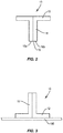
- the tip 15 can include different shapes depending upon the use, including but not limited to a pointed shape as illustrated in Figure 1 and a flat shape as illustrated in Figure 2 .
- the ends 16a, 16b of the charges 9a, 9b should be aligned to prevent resin pooling.
- the stringer 10 can be used in a variety of contexts.
- Figure 3 includes the stringer 10 connected to a panel 100, such as but not limited to the wing skin, fuselage, and airframe of a vehicle.
- Figure 4 illustrates a tooling assembly 20 employed to form the stringers 10.
- the tooling assembly 20 generally includes a die assembly 30 and a punch assembly 40.
- the die assembly 30 includes a pair of form blocks 31, 32 that are spaced apart to form a die cavity 33.
- the form blocks 31, 32 can be constructed from relatively rigid material, such as but not limited to wood, metal, ceramic or a composite.
- the first form block 31 includes an inner surface 34 and a top surface 35.
- the second form block 32 includes an inner surface 36 and a top surface 37.
- a pair of L-shape, elongated brackets 38, 39 are mounted on a plate 60 on opposite sides of form blocks 31, 32.
- the brackets 38, 39 retain the form blocks 31, 32 on the plate 60 as well as react lateral forming forces generated by the form blocks 31, 32.
- One or more actuators 89 can move the form blocks 31, 32 to adjust a width of the die cavity 33.
- a pair of inflatable hoses 61, 62 sometimes referred to as bags or bladders are sandwiched between the brackets 38, 39 and the form blocks 31, 32.
- the hoses 61, 62 are configured to be coupled with a suitable source of pressurized air (not shown) to be pressurized in order to apply a lateral force on the form blocks 31, 32 during the fabrication processes.
- Other mechanisms can be provided to apply lateral force to the form blocks 31, 32.
- the punch assembly 40 includes a punch 41 that can include a first section of a first punch plate 42 and a second section of a second punch plate 43.
- One or more actuators 49 are configured to power the punch plates 42, 43 into and out of the die cavity 33.
- the punch plates 42, 43 are configured to move separately and relative to each other.
- the first punch plate 42 can move into and out of the die cavity 33 regardless of the position and movement of the second punch plate 43.
- the second punch plate 43 can move into and out of the die cavity 33 regardless of the position and movement of the first punch plate 42.
- the punch plates 42, 43 can move simultaneously during the fabrication (e.g., both punch plates 42, 43 are aligned and move at the same time into the die cavity 33) or can move at different times (e.g., first punch plate 42 is moved into the die cavity 33 followed by the second punch plate 43 being moved into the die cavity 33).
- the inner sides of the punch plates 42, 43 can abut together and slide across each other during relative movement.
- the inner sides can be flat to facilitate the relative movement.
- the punch plates 42, 43 can be spaced apart by a gap.
- the punch plates 42, 43 can be formed of a suitable rigid material, such as but not limited to metal, ceramic or a composite.
- the punch assembly 40 also includes first and second flange plates 44, 45.
- Each of the flange plates 44, 45 extends transversely outward from the respective first and second punch plates 42, 43. This can include the flange plates 44, 45 being perpendicular to the first and second punch plates 42, 43.
- One or more actuators 48 move the flange plates 44, 45 up and down along the punch plates 42, 43 to form the flanges 12a, 12b as will be explained below.
- the flange plates 44, 45 can move independently or the flange plates 44, 45 can move together.
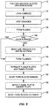
- Figure 5 includes a flowchart of the steps of fabricating a stringer 10.
- Figures 6-16 illustrate the individual steps and correspond to the flowchart.
- Figure 6 illustrates the tooling assembly 20 in preparation for the fabrication process.
- the punch 41 that includes the first and second punch plates 42, 43 is elevated above the die cavity 33 formed between the form blocks 31, 32.
- the flange plates 44, 45 are also elevated above the form blocks 31, 32.
- material sheets 50 are positioned on each of the form blocks 31, 32 (block 110).
- the material sheets 50 are constructed from material that has a lower adherence value relative to the first and second charges 9a, 9b than the first and second punch plates 42, 43.
- the material sheets 50 provide for the first and second charges 9a, 9b to slide along the first and second form blocks 31, 32 respectively when adhered to the first and second punch plates 42, 43.
- the material sheets 50 can be constructed from a variety of materials, including but not limited to Teflon.
- the material sheets 50 are sized to extend over the inner surface 34 and top surface 35 of the form block 31 and the inner surface 36 and top surface 37 of the form block 32.
- the material sheets 50 can extend over an entirety or limited section of these surfaces.
- flat, multi-ply composite charges 9a, 9b are loaded onto the form blocks 31, 32 while the first and second punch plates 42, 43 are in elevated positions (block 115).
- the first and second punch plates 42, 43 can be positioned with ends 46, 47 being aligned.
- the first and second charges 9a, 9b are positioned with the ends 16a, 16b abutting together and centered over the die cavity 33.
- the charges 9a, 9b can be heated (block 120).
- Figure 9 illustrates a heating blanket 80 loaded onto the charges 9a, 9b.
- the heating blanket 80 heats the charges 9a, 9b which can make the resin more liquid which can facilitate forming the charges 9a, 9b.
- the charges 9a, 9b are maintained at a lower temperature and stored at a low temperature.
- the charges 9a, 9b are removed from the storage and placed on the tooling assembly 20 which is in an environment with a higher temperature.
- the charges 9a, 9b can be elevated in temperature due to exposure in the warmer environment and/or other means such as the heating blanket 80 or exposure to radiant or inductive type heaters.
- Heating also increases an adherence between the punch plates 42, 43 and the charges 9a, 9b from a very low cold temperature state where the resin tends to be hard and less sticky. If necessary, adherence can also be accomplished using mechanical aspects, such as but not limited to notches in one of the punch plates 42, 43 or charges 9a, 9b that engage with the opposing member. Mechanical fasteners can also be used to adhere the charges 9a, 9b to the punch plates 42, 43.
- the first and second punch plates 42, 43 are then moved into the die cavity 33 to form the blades 11a, 11b (block 125) and illustrated in Figure 10 .
- the first and second punch plates 42, 43 contact against and drive the ends 16a, 16b and center sections of the first and second charges 9a, 9b into the die cavity 33. This movement begins to form the blades 11a, 11b of the charges 9a, 9b in the die cavity 33.
- first and second punch plates 42, 43 contact against first and second charges 9a, 9b
- the charges 9a, 9b adhere to the punch plates 42, 43. This can be caused by the tackiness of the charges 9a, 9b.
- the charges 9a, 9b adhere to and move with the punch plates 42, 43.
- the charges 9a, 9b slide along the surfaces of the form blocks 31, 32 due to the contact with the material sheets 50 as the adherence value is lower between the charges 9a, 9b and the material sheets 50 than between the charges 9a, 9b and the punch plates 42, 43.
- the position of the ends 16a, 16b in the die cavity 33 is then determined (block 130). If the ends 16a, 16b are aligned, no relative adjustment is necessary. When the ends 16a, 16b are misaligned, the relative positioning of the ends 16a, 16b is adjusted. As illustrated in Figure 11 , the misalignment can be caused by one of the ends 16a, 16b being positioned deeper into the die cavity 33.
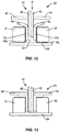
- one of the punch plates 42, 43 is moved relative to the other punch plate 42, 43 (block 135). This can include moving the punch plate 42, 43 that is adhered to the charge 9a, 9b positioned upward in the die cavity 33 an additional amount into the die cavity 33. In the example of Figure 11 , this would include moving punch plate 43 and corresponding charge 9b deeper into the die cavity 33. As illustrated in Figure 12 , punch plate 43 is moved relative to punch plate 42 farther into the die cavity 33 as illustrated by arrow A. The punch plate 43 is moved a distance into the die cavity 33 until the ends 16a, 16b are aligned. During the movement, punch plate 42 and corresponding charge 9a can be stationary.
- the alignment can include moving the punch plate 42, 43 of the more-elevated charge 9a, 9b an additional amount into the die cavity 33. This moves the shallower one of the charges 9a, 9b farther into the die cavity 33 and into alignment with the other charge 9a, 9b.
- the alignment can also include moving the punch plate 42, 43 adhered to the deeper one of the charges 9a, 9b (i.e., the charge 9a, 9b that is farther into the die cavity 33). In this method, the applicable punch plate 42, 43 is moved a distance out of the die cavity 33 until the ends 16a, 16b are aligned.
- the process can include the charges 9a, 9b being fully formed into the die cavity 33. Once formed, the ends 46, 47 can be aligned by individual movement of the punch plates 42, 43 as described above.
- the process can also include performing an initial first punch by moving the punch plates 42, 43 and corresponding charges 9a, 9b a first amount into the die cavity 33. Once the initial first punch is complete, the ends 46, 47 can be aligned in the die cavity 33 by moving one of the punch plates 42, 43 as described above. After alignment, a second punch can occur that moves the punch plates 42, 43 and corresponding charges 9a, 9b an additional amount deeper into the die cavity 33.
- the ends 46, 47 of the charges 9a, 9b can be aligned by moving the punch plates 42, 43 relative to each other as described above.
- the overall punch process can include two separate steps, or can include more than two steps with each step forming the charges 9a, 9b deeper into the die cavity 33.
- the flange plates 44, 45 are brought into contact with the charges 9a, 9b to form the flanges 12a, 12b (block 140).
- the flange plates 44, 45 apply pressure to the charges 9a, 9b to form the flanges 12a, 12b against the top surfaces 35, 37 of the form blocks 31, 32.
- the flange plates 44, 45 can simultaneously be brought into contact with their respective first and second charges 9a, 9b.
- the flange plates 44, 45 can also be brought individually into contact with their respective charges 9a, 9b.
- the form blocks 31, 32 can then be moved outward to expand the die cavity 33.
- One or more actuators 89 can be connected to the form blocks 31, 32 to control their movement.
- the punch plates 42, 43 and the flange plates 44, 45 are then retracted upward from the form blocks 31, 32 (block 145).
- the sequencing of the retraction of the punch plates 42, 43 and flange plates 44, 45 can occur in various orders.
- the form blocks 31, 32 are moved together against the charges 9a, 9b (block 150).
- the compression forces applied through the form blocks 31, 32 can secure the charges together.
- one or both flange plates 44, 45 can be brought into contact with the charges 9a, 9b as illustrated in Figure 16 (block 155).
- a filler material can be placed in a groove formed between the inner sides of the flanges 12a, 12b.
- the flange plates 44, 45 can be elevated and the form blocks 31, 32 can be moved outward (block 160). Once released, the stringer 10 can be removed from the die cavity 33.
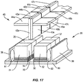
- the punch plates 42, 43 and flange plates 44, 45 can be a single component that extends the length of the stringer 10. Actuation includes the entire punch 41 moving into or out of the die cavity 33. As illustrated in Figure 17 , the punch plates 42, 43 and flange plates 44, 45 can be divided into separate segments that extend the length of the stringer 10. The number and size of each of the separate segments can vary. The size of each of the segments can be the same or can be different. Each segment can be moved by an actuator to fabricate the stringer 10 as explained above. The segments can be independently moved relative to the other segments. The punch plates 42, 43 of each segment can be individually adjusted to align the ends 16a, 16b of the charges 9a, 9b. The form blocks 31, 32 can also be divided into separate segments. The separate segments can be the same or different sizes. Further, the segments can be individually moved by one or more actuators as explained above.
- one or more sensors 90 can be positioned to sense the positions of the ends 16a, 16b in the die cavity 33.
- Various sensor types may be used, including but not limited to a camera.
- the one or more sensors 90 can be positioned at various locations along the tooling assembly 20.
- the position can include one or more sensors 90 positioned at one or both opposing ends of the die cavity 33 to sense alignment of one or both of the inboard and outboard ends of the stringer 10.
- one or more sensors 90 can be positioned along one or more of the separate component sections.
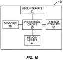
- a control unit 95 ( Figure 19 ) that includes the one or more sensors 90 can control the operation of the tooling assembly 20.
- the control unit 95 can signal control steps to control the various components of the tooling assembly 20. This includes but is not limited to signaling control steps to the actuators 48, 49 that control the punch plates 42, 43 and the flange plates 44, 45.
- the control unit 95 includes one or more processing circuits (shown as processing circuit 96) that may include one or more microprocessors, Application Specific Integrated Circuits (ASICs), or the like, configured with appropriate software and/or firmware.
- a computer readable storage medium (shown as memory circuit 97) stores data and computer readable program code that configures the processing circuit 96 to implement the techniques described above.
- Memory circuit 97 is a non-transitory computer readable medium, and may include various memory devices such as random access memory, read-only memory, and flash memory.
- a user interface 91 includes one or more user input devices such as a keypad, touchpad, function keys, scroll wheel, or other type of computer input device.
- the user interface 91 can include a display screen, such as a liquid crystal display (LCD) or touch screen display which also functions as a user input device.
- LCD liquid crystal display
- the user interface 91 provides for the worker to control the functions of the various components that are in communication with the control unit 95.
- a system interface 98 is configured to communications with a remote source. This can include a remote control source used by the worker who is remote from the tooling assembly 20.
- the system interface 98 can include a transceiver configured to wirelessly communicate with the remote source.
- the system interface 98 can also provide for hardwire connection with the remote source.
- the system interface 98 may also provide for the supply of power from a remote source.
- the control unit 95 can also include a power source (not illustrated).
- the power source can be used in the event of failure of receiving power from the remote source.
- the power source can also provide power to just one or more limited elements, such as the processing circuit 96 and the memory circuit 97.
- the power source may be rechargeable battery pack that includes a set of battery cells configured to power electrical equipment.
- the alignment of the ends 16a, 16b of the charges 9a, 9b in the die cavity 33 can be an automatic or manual process.
- one or more visual identification programs can be stored in the memory circuit 97 and used by the processing circuit 96 to determine the relative alignment of the ends 16a, 16b.
- the processing circuit 96 can then move the punch plates 42, 43 accordingly to align the ends 16a, 16b.
- the alignment of the ends 16a, 16b can be shown on a display that is part of the user interface 91.
- the display can also include a reference (e.g., a ruler). An operator can see the relative positioning of the ends 16a, 16b and then control the punch plates 42, 43 through the user interface 91 to achieve proper alignment and required punch depth of both charges 9a, 9b.
- the stringers 10 and fabrication methodologies can being used in a variety of potential applications, particularly in the transportation industry, including for example, aerospace, marine, automotive applications and other application where automated layup equipment can be used.
- the stringers 10 and methodologies can be used in the context of a vehicle manufacturing and service method 236 as illustrated in Figure 20 and a vehicle 238 such as an aircraft as illustrated in Figure 21 .
- exemplary methods 236 can include specification and design 240 of the vehicle 238 and material procurement 242.
- component and subassembly manufacturing 244 and system integration 246 of the vehicle 238 takes place. Thereafter, the vehicle 238 can go through certification and delivery 248 in order to be placed in service 250.
- the vehicle 238 is scheduled for routine maintenance and service 250, which can also include modification, reconfiguration, refurbishment, and so on.
- a system integrator can include without limitation any number of vehicle manufacturers and major-system subcontractors
- a third party can include without limitation any number of vendors, subcontractors, and suppliers
- an operator can be an airline, leasing company, military entity, service organization, and so on.
- the vehicle 238 produced by exemplary method 236 can include an airframe 254 with a plurality of systems 256 and an interior 258.
- high-level systems 256 include one or more of a propulsion system 260, an electrical system 262, a hydraulic system 264, and an environmental system 266. Any number of other systems can be included.
- an aerospace example is shown, the principles of the disclosure can be applied to other industries, such as the marine and automotive industries.
- Systems and methods embodied herein can be employed during any one or more of the stages of the production and service method 236 ( Figure 20 ).
- components or subassemblies corresponding to component and subassembly manufacturing 244 can be fabricated or manufactured in a manner similar to components or subassemblies produced while the vehicle 238 is in service.
- one or more apparatus embodiments, method embodiments, or a combination thereof can be utilized during the component and subassembly manufacturing 244 and system integration 246, for example, by expediting assembly of or reducing the cost of a vehicle 238.
- one or more of apparatus embodiments, method embodiments, or a combination thereof can be utilized while the vehicle 238 is in service, for example and without limitation, to maintenance and service 252.
- the stringer 10 can be used to support different panels, including but not limited to a wing, airframe, and fuselage of a vehicle.
- the stringer 10 can be used with a variety of vehicles.
- One vehicle includes a commercial aircraft that includes rows of seats each configured to accommodate a passenger.
- Other vehicles include but are not limited to manned aircraft, unmanned aircraft, manned spacecraft, unmanned spacecraft, manned rotorcraft, unmanned rotorcraft, satellites, rockets, missiles, manned terrestrial vehicles, unmanned terrestrial vehicles, manned surface water borne vehicles, unmanned surface water borne vehicles, manned sub-surface water borne vehicles, unmanned sub-surface water borne vehicles, and combinations thereof.
Landscapes
- Engineering & Computer Science (AREA)
- Mechanical Engineering (AREA)
- Chemical & Material Sciences (AREA)
- Composite Materials (AREA)
- Remote Sensing (AREA)
- Aviation & Aerospace Engineering (AREA)
- Materials Engineering (AREA)
- Manufacturing & Machinery (AREA)
- Transportation (AREA)
- Moulding By Coating Moulds (AREA)
- Casting Or Compression Moulding Of Plastics Or The Like (AREA)
Abstract
Description
- The present disclosure generally relates to a process of stringer fabrication. More particularly, the present disclosure relates to devices and methods for aligning blade tips of charges during fabrication of a composite stringer for a vehicle.
- Composite reinforcing substructures such as stringers, sometimes referred to as blade stiffeners, are frequently used in the marine and aircraft industries. These stringers can be fabricated by combining two or more charges. The stringer includes a blade section and a flange section with opposing flanges that extend outward from each side of the blade section.
- During the fabrication process, the charges can be formed into an L-shaped cross-section. This forming includes forcing ends of each of the charges into a die cavity to form the blade section. The ends of the charges inserted into the die cavity and that form the blade section should be aligned in the die cavity. In the event the tips become misaligned, resin can pool at the end of the blade section during curing. The pooled resin can experience cracking when the stringer is exposed to certain thermal cycles at extreme temperatures.
- One aspect is directed to a method of fabricating a composite stringer for a vehicle. The method includes positioning first and second charges at a die cavity formed between first and second form blocks. The method includes inserting a first punch plate into the die cavity and driving a first end of the first charge along the first form block and into the die cavity, and inserting a second punch plate into the die cavity and driving a first end of the second charge along the second form block and into the die cavity. The method includes moving the first punch plate relative to the second punch plate when the first ends are misaligned and moving the first charge relative to the first form block and aligning the first ends of the first and second charges in the die cavity. The method also includes that while the aligned first ends are in the die cavity, forming flanges at second ends of the first and second charges. The method includes moving the first and second punch plates out of the die cavity, and compressing the first and second charges between the first and second form blocks.
- In another aspect, the method also includes adhering the first charge to the first punch plate to prevent relative movement between the first charge and the first punch plate and moving the first charge along the first form block while driving the first end of the first charge into the die cavity.
- In another aspect, the method also includes adhering the second charge to the second punch plate to prevent relative movement between the second charge and the second punch plate and moving the second charge along the second form block while driving the first end of the second charge into the die cavity.
- In another aspect, the method also includes heating the first and second charges prior to driving the first ends of the first and second charges into the die cavity.
- In another aspect, the method includes contacting the first punch plate against the second punch plate while moving the first punch plate into the die cavity.
- In another aspect, the method includes simultaneously inserting the first and second punch plates into the die cavity.
- In another aspect, the method also includes positioning material sheets on each of the first and second form blocks prior to inserting the first and second charges into the die cavity with the material sheets having a lower adherence value relative to the first and second charges than the first and second punch plates.
- In another aspect, moving the first punch plate relative to the second punch plate and moving the first charge relative to the first form block and aligning the first ends of the first and second charges in the die cavity includes moving each of the first punch plate and the first end of the first charge farther into the die cavity.
- One aspect is directed to a method of fabricating a composite stringer for a vehicle. The method includes positioning first and second charges over a die cavity formed between first and second form blocks. The method includes contacting the first and second charges with a punch and driving a first end of each of the charges into the die cavity. The method includes that when the first ends are misaligned in the die cavity, moving a first section of the punch that is adhered to the first charge relative to a second section of the punch that is adhered to the second charge and moving the first charge and aligning the first end of the first charge with the first end of the second charge in the die cavity. The method includes that while the aligned first ends are in the die cavity, forming flanges with second end sections of the first and second charges. The method includes removing the punch from the die cavity, and compressing together the charges in the die cavity.
- In another aspect, the method also includes positioning a sheet on each of the first and second form blocks with the sheets having a lower adherence value than surfaces of the first and second form blocks to prevent adherence of the first charge to the first form block and the second charge to the second form block when the first ends of each of the charges are driven into the die cavity and aligned.
- In another aspect, the method also includes sliding the first charge against the sheet on the first form block and sliding the second charge against the sheet on the second form block while driving the first end of each of the charges into the die cavity.
- In another aspect, contacting the first and second charges with the punch and driving the first end of each of the charges into the die cavity includes contacting a first punch plate section against the first charge and driving the first charge into the die cavity and separately contacting a second punch plate section against the second charge and driving the second charge into the die cavity.
- In another aspect, moving the first section of the punch that is adhered to the first charge relative to a second section of the punch that is adhered to the second charge and moving the first charge and aligning the first end of the first charge with the first end of the second charge in the die cavity includes moving the first section of the punch farther into the die cavity and moving the first end of the first charge farther into the die cavity.
- In another aspect, the method also includes displaying on a display monitor relative positions of the first ends of the first and second charges in the die cavity.
- In another aspect, the method is for a panel of a vehicle manufactured according to the method. In another aspect, the method is for a vehicle with a panel manufactured according to the method.
- One aspect is directed to a device to fabricate a composite stringer for a vehicle. The device includes a die cavity formed between first and second form blocks. First and second punch plates are positioned in proximity to the die cavity with each of the first and second punch plates including an inner face, an outer face, and a contact edge that extends between the inner and outer faces with the first and second punch plates being positioned with the inner faces facing together and the contact edges closer to the die cavity than an opposing edges. A first flange plate is positioned at and transverse to the outer face of the first punch plate and a second flange plate is positioned at and transverse to the outer face of the second punch plate. One or more actuators are operatively connected to the first and second punch plates to individually move each of the punch plates relative to the die cavity and relative to each other between a first position with the contact edge positioned out of the die cavity and a second position with the contact edge positioned in the die cavity.
- In another aspect, the inner faces of the first and second punch plates are in contact.
- In another aspect, the one or more actuators are operatively connected to the first and second flange plates to individually move each of the first and second flange plates relative to each other and towards and away from the first and second form blocks.
- In another aspect, the device includes sensors configured to detect a relative position in the die cavity between ends of the first and second charges.
- Further, the disclosure comprises embodiments according to the following clauses:
- Clause 1. A method of fabricating a composite stringer for a vehicle, the method comprising:
- positioning first and second charges (9a, 9b) over a die cavity (33) formed between first and second form blocks (31, 32);
- contacting the first and second charges (9a, 9b) with a punch (41) and driving a first end (16a, 16b) of each of the first and second charges (9a, 9b) into the die cavity (33);
- when the first ends (16a, 16b) are misaligned in the die cavity (33), moving a first section of the punch (41) that is adhered to the first charge (9a) relative to a second section of the punch (41) that is adhered to the second charge (9b) and moving the first charge (9a) and aligning the first end (16a) of the first charge (9a) with the first end (16b) of the second charge (9b) in the die cavity (33);
- when the first ends (16a, 16b) are aligned in the die cavity (33), forming flanges (12a, 12b) with second end sections of the first and second charges (9a, 9b);
- removing the punch (41) from the die cavity (33); and
- compressing together the charges (9a, 9b) in the die cavity (33).
- Clause 2. The method of clause 1, further comprising positioning a material sheet (50) on each of the first and second form blocks (31, 32) with the material sheets (50) having a lower adherence value than surfaces of the first and second form blocks (31, 32) to prevent adherence of the first charge (9a) to the first form block (31) and the second charge (9b) to the second form block (32) when the first ends (16a, 16b) of the first and second charges (9a, 9b) are driven into the die cavity (33) and aligned.
- Clause 3. The method of clause 2, further comprising sliding the first charge (9a) against the material sheet (50) on the first form block (31) and sliding the second charge (9b) against the material sheet (50) on the second form block (32) while driving the first ends (16a, 16b) of each of the first and second charges (9a, 9b) into the die cavity (33).
- Clause 4. The method of clauses 1-3, wherein contacting the first and second charges (9a, 9b) with the punch (41) and driving the first ends (16a, 16b) of each of the first and second charges (9a, 9b) into the die cavity (33) comprises contacting a first punch plate section (42) against the first charge (9a) and driving the first charge (9a) into the die cavity (33) and separately contacting a second punch plate section (43) against the second charge (9b) and driving the second charge (9b) into the die cavity (33).
- Clause 5. The method of clauses 1-4, wherein moving the first section (42) of the punch (41) that is adhered to the first charge (9a) relative to a second section (43) of the punch (41) that is adhered to the second charge (9b) and moving the first charge (9a) and aligning the first end (16a) of the first charge (9a) with the first end (16b) of the second charge (9b) in the die cavity (33) comprises moving the first section (42) of the punch (41) farther into the die cavity (33) and moving the first end (16a) of the first charge (9a) farther into the die cavity (33).
- Clause 6. The method of clauses 1-5, further comprising displaying on a display monitor relative positions of the first ends (16a, 16b) of the first and second charges (9a, 9b) in the die cavity (33).
- Clause 7. A panel (100) of a vehicle (238) manufactured according to the method of clause 1.
- Clause 8. A vehicle (238) with a panel (100) manufactured according to the method of clause 1.
- Clause 9. A method of fabricating a composite stringer for a vehicle, the method comprising:
- positioning first and second charges (9a, 9b) at a die cavity (33) formed between first and second form blocks (31, 32);
- inserting a first punch plate (42) into the die cavity (33) and driving a first end (16a) of the first charge (9a) along the first form block (31) and into the die cavity (33);
- inserting a second punch plate (43) into the die cavity (33) and driving a first end (16b) of the second charge (9b) along the second form block (32) and into the die cavity (33);
- moving the first punch plate (42) relative to the second punch plate (43) when the first ends (16a, 16b) are misaligned and moving the first charge (9a) relative to the first form block (31) and aligning the first ends (16a, 16b) of the first and second charges (9a, 9b) in the die cavity (33);
- when the first ends (16a, 16b) are aligned in the die cavity (33), forming flanges (12a, 12b) at second ends of the first and second charges (9a, 9b);
- moving the first and second punch plates (42, 43) out of the die cavity (33); and
- compressing the first and second charges (9a, 9b) between the first and second form blocks (31, 32).
-
Clause 10. The method of clause 9, further comprising adhering the first charge (9a) to the first punch plate (42) to prevent relative movement between the first charge (9a) and the first punch plate (42) and moving the first charge (9a) along the first form block (31) while driving the first end (16a) of the first charge (9a) into the die cavity (33). -
Clause 11. The method ofclause 10, further comprising adhering the second charge (9b) to the second punch plate (43) to prevent relative movement between the second charge (9b) and the second punch plate (43) and moving the second charge (9b) along the second form block (32) while driving the first end (16b) of the second charge (9b) into the die cavity (33). -
Clause 12. The method of clauses 9-11, further comprising heating the first and second charges (9a, 9b) prior to driving the first ends (16a, 16b) of the first and second charges (9a, 9b) into the die cavity (33). -
Clause 13. The method of clauses 9-12, further comprising contacting the first punch plate (42) against the second punch plate (43) while moving the first punch plate (42) into the die cavity (33). - Clause 14. The method of clauses 9-13, further comprising simultaneously inserting the first and second punch plates (42, 43) into the die cavity (33).
-
Clause 15. The method of clauses 9-14, further comprising positioning material sheets (50) on each of the first and second form blocks (31, 32) prior to inserting the first and second charges (9a, 9b) into the die cavity (33), the material sheets (50) having a lower adherence value relative to the first and second charges (9a, 9b) than the first and second punch plates (42, 43). - Clause 16. The method of clauses 9-15, wherein moving the first punch plate (42) relative to the second punch plate (43) and moving the first charge (9a) relative to the first form block (31) and aligning the first ends (16a, 16b) of the first and second charges (9a, 9b) in the die cavity (33) comprises moving each of the first punch plate (42) and the first end (16a) of the first charge (9a) farther into the die cavity (33).
- Clause 17. A device to fabricate a composite stringer for a vehicle, the device comprising:
- a die cavity (33) formed between first and second form blocks (31, 32);
- first and second punch plates (42, 43) positioned in proximity to the die cavity (33), each of the first and second punch plates (42, 43) comprising an inner face, an outer face, and a contact end (46, 47) that extends between the inner and outer faces, the first and second punch plates (42, 43) being positioned with the inner faces facing together and the contact ends (46, 47) closer to the die cavity (33) than an opposing ends;
- a first flange plate (44) positioned at and transverse to the outer face of the first punch plate (42) and a second flange plate (45) positioned at and transverse to the outer face of the second punch plate (43); and
- one or more actuators (48) operatively connected to the first and second punch plates (42, 43) to individually move each of the first and second punch plates (42, 43) relative to the die cavity (33) and relative to each other between a first position with the contact end (46, 47) positioned out of the die cavity (33) and a second position with the contact end (46, 47) positioned in the die cavity (33).
- Clause 18. The device of clause 17, wherein the inner faces of the first and second punch plates (42, 43) are in contact.
- Clause 19. The device of clause 18, wherein the one or more actuators (89) are operatively connected to the first and second flange plates (44, 45) to individually move each of the first and second flange plates (44, 45) relative to each other and towards and away from the first and second form blocks (31, 32).
-
Clause 20. The device of claims 17-19, further comprising one or more sensors (90) that detect a relative position between ends (16a, 16b) of first and second charges (9a, 9b) in the die cavity (33). -
-
Figure 1 is a perspective view of a stringer. -
Figure 2 is an end view of a stringer. -
Figure 3 is an end view of a stringer attached to a wing skin of a vehicle. -
Figure 4 is a perspective view of a tooling assembly. -
Figure 5 is a flowchart diagram of a method of fabricating a composite stringer for a vehicle. -
Figures 6-16 are schematic illustrations of steps of fabricating a composite stringer for a vehicle using the tooling assembly shown inFigure 4 . -
Figure 17 is a perspective view of a tooling assembly having segmented punch plates and flange plates. -
Figure 18 is a perspective view of sensors positioned at a die cavity of a tooling assembly. -
Figure 19 is a schematic diagram of a control unit. -
Figure 20 is a flow diagram of a vehicle production and service methodology. -
Figure 21 is a block diagram of a vehicle. - The present disclosure includes methods and devices of fabricating a stringer for a stiffened stringer panel. The stringer can be constructed from two charges that are formed together into the stringer. During fabricating, the ends of the charges can be formed in a die cavity. When the ends are misaligned in the die cavity, one of the charges can be moved in the die cavity to align the ends. The device used for fabricating the charges can include a punch with separate punch plates that move the ends of the charges into the die cavity. The punch plates can be separately moved to adjust the position of the charges and align the ends.
-
Figure 1 illustrates a sectional view of astringer 10 that is formed by afirst charge 9a and asecond charge 9b that are positioned in a back-to-back orientation. Thefirst charge 9a includes ablade 11a and aflange 12a. Likewise, thesecond charge 9b includes ablade 11b and aflange 12b. Thecharges charges stringer 10 includes each of thecharges - The
stringer 10 includes a T-shape cross section with ablade section 11 formed byblades flange section 12 formed byflanges flanges blade section 11 or can be aligned at different angles. In one design as illustrated inFigure 1 , theflange section 12 is perpendicular to theblade section 11. Other designs include theflange section 12 being at non-perpendicular angles relative to theblade section 11. Thestringer 10 can include lengths L that extend between a first and second ends 13, 14. The height H measured between atip 15 of theblade section 11 and top of theflange section 12 can also vary. A width W measured along theflange section 12 can also vary. The thicknesses of theblade sections 11 andflange sections 12 can also vary. Thestringer 10 can also include a composite filler material (not illustrated) positioned between theblades - The
tip 15 of theblade section 11 includesends charges tip 15 can include different shapes depending upon the use, including but not limited to a pointed shape as illustrated inFigure 1 and a flat shape as illustrated inFigure 2 . The ends 16a, 16b of thecharges stringer 10 can be used in a variety of contexts.Figure 3 includes thestringer 10 connected to apanel 100, such as but not limited to the wing skin, fuselage, and airframe of a vehicle. -
Figure 4 illustrates atooling assembly 20 employed to form thestringers 10. Thetooling assembly 20 generally includes adie assembly 30 and apunch assembly 40. - The
die assembly 30 includes a pair of form blocks 31, 32 that are spaced apart to form adie cavity 33. The form blocks 31, 32 can be constructed from relatively rigid material, such as but not limited to wood, metal, ceramic or a composite. Thefirst form block 31 includes aninner surface 34 and atop surface 35. Likewise, thesecond form block 32 includes aninner surface 36 and atop surface 37. - A pair of L-shape,
elongated brackets plate 60 on opposite sides of form blocks 31, 32. Thebrackets plate 60 as well as react lateral forming forces generated by the form blocks 31, 32. One ormore actuators 89 can move the form blocks 31, 32 to adjust a width of thedie cavity 33. A pair ofinflatable hoses brackets hoses - The
punch assembly 40 includes apunch 41 that can include a first section of afirst punch plate 42 and a second section of asecond punch plate 43. One ormore actuators 49 are configured to power thepunch plates die cavity 33. Thepunch plates first punch plate 42 can move into and out of thedie cavity 33 regardless of the position and movement of thesecond punch plate 43. Likewise, thesecond punch plate 43 can move into and out of thedie cavity 33 regardless of the position and movement of thefirst punch plate 42. Thepunch plates plates first punch plate 42 is moved into thedie cavity 33 followed by thesecond punch plate 43 being moved into the die cavity 33). - The inner sides of the
punch plates punch plates punch plates - The
punch assembly 40 also includes first andsecond flange plates flange plates second punch plates flange plates second punch plates more actuators 48 move theflange plates punch plates flanges flange plates flange plates -
Figure 5 includes a flowchart of the steps of fabricating astringer 10.Figures 6-16 illustrate the individual steps and correspond to the flowchart.Figure 6 illustrates thetooling assembly 20 in preparation for the fabrication process. Thepunch 41 that includes the first andsecond punch plates die cavity 33 formed between the form blocks 31, 32. Theflange plates - As illustrated in
Figure 7 ,material sheets 50 are positioned on each of the form blocks 31, 32 (block 110). Thematerial sheets 50 are constructed from material that has a lower adherence value relative to the first andsecond charges second punch plates material sheets 50 provide for the first andsecond charges second punch plates material sheets 50 can be constructed from a variety of materials, including but not limited to Teflon. Thematerial sheets 50 are sized to extend over theinner surface 34 andtop surface 35 of theform block 31 and theinner surface 36 andtop surface 37 of theform block 32. Thematerial sheets 50 can extend over an entirety or limited section of these surfaces. - As illustrated in
Figure 8 , flat, multi-plycomposite charges second punch plates second punch plates second charges ends die cavity 33. - The
charges Figure 9 illustrates aheating blanket 80 loaded onto thecharges heating blanket 80 heats thecharges charges charges charges tooling assembly 20 which is in an environment with a higher temperature. Thecharges heating blanket 80 or exposure to radiant or inductive type heaters. Heating also increases an adherence between thepunch plates charges punch plates charges charges punch plates - The first and
second punch plates die cavity 33 to form theblades Figure 10 . During the movement, the first andsecond punch plates ends second charges die cavity 33. This movement begins to form theblades charges die cavity 33. - As the first and
second punch plates second charges charges punch plates charges charges punch plates charges material sheets 50 as the adherence value is lower between thecharges material sheets 50 than between thecharges punch plates - The position of the
ends die cavity 33 is then determined (block 130). If the ends 16a, 16b are aligned, no relative adjustment is necessary. When the ends 16a, 16b are misaligned, the relative positioning of theends Figure 11 , the misalignment can be caused by one of theends die cavity 33. - To align the
ends punch plates other punch plate 42, 43 (block 135). This can include moving thepunch plate charge die cavity 33 an additional amount into thedie cavity 33. In the example ofFigure 11 , this would include movingpunch plate 43 andcorresponding charge 9b deeper into thedie cavity 33. As illustrated inFigure 12 ,punch plate 43 is moved relative to punchplate 42 farther into thedie cavity 33 as illustrated by arrow A. Thepunch plate 43 is moved a distance into thedie cavity 33 until theends punch plate 42 andcorresponding charge 9a can be stationary. - As described above, the alignment can include moving the
punch plate elevated charge die cavity 33. This moves the shallower one of thecharges die cavity 33 and into alignment with theother charge punch plate charges charge applicable punch plate die cavity 33 until theends - The process can include the
charges die cavity 33. Once formed, the ends 46, 47 can be aligned by individual movement of thepunch plates punch plates corresponding charges die cavity 33. Once the initial first punch is complete, the ends 46, 47 can be aligned in thedie cavity 33 by moving one of thepunch plates punch plates corresponding charges die cavity 33. Once complete, the ends 46, 47 of thecharges punch plates charges die cavity 33. - During the punching process, the form blocks 31, 32 remain in position against the
charges Figure 12 . - Next, as illustrated in
Figure 13 , theflange plates charges flanges flange plates charges flanges top surfaces flange plates second charges flange plates respective charges - As illustrated in
Figure 14 , the form blocks 31, 32 can then be moved outward to expand thedie cavity 33. One ormore actuators 89 can be connected to the form blocks 31, 32 to control their movement. Thepunch plates flange plates punch plates flange plates - Next, as illustrated in
Figure 15 , the form blocks 31, 32 are moved together against thecharges flange plates charges Figure 16 (block 155). Further, a filler material can be placed in a groove formed between the inner sides of theflanges - The
flange plates stringer 10 can be removed from thedie cavity 33. - The
punch plates flange plates stringer 10. Actuation includes theentire punch 41 moving into or out of thedie cavity 33. As illustrated inFigure 17 , thepunch plates flange plates stringer 10. The number and size of each of the separate segments can vary. The size of each of the segments can be the same or can be different. Each segment can be moved by an actuator to fabricate thestringer 10 as explained above. The segments can be independently moved relative to the other segments. Thepunch plates ends charges - As illustrated in
Figure 18 , one ormore sensors 90 can be positioned to sense the positions of theends die cavity 33. Various sensor types may be used, including but not limited to a camera. The one ormore sensors 90 can be positioned at various locations along thetooling assembly 20. The position can include one ormore sensors 90 positioned at one or both opposing ends of thedie cavity 33 to sense alignment of one or both of the inboard and outboard ends of thestringer 10. In segmented punching assemblies (as illustrated inFigure 17 ), one ormore sensors 90 can be positioned along one or more of the separate component sections. - A control unit 95 (
Figure 19 ) that includes the one ormore sensors 90 can control the operation of thetooling assembly 20. Thecontrol unit 95 can signal control steps to control the various components of thetooling assembly 20. This includes but is not limited to signaling control steps to theactuators punch plates flange plates Figure 19 , thecontrol unit 95 includes one or more processing circuits (shown as processing circuit 96) that may include one or more microprocessors, Application Specific Integrated Circuits (ASICs), or the like, configured with appropriate software and/or firmware. A computer readable storage medium (shown as memory circuit 97) stores data and computer readable program code that configures theprocessing circuit 96 to implement the techniques described above.Memory circuit 97 is a non-transitory computer readable medium, and may include various memory devices such as random access memory, read-only memory, and flash memory. - A user interface 91 includes one or more user input devices such as a keypad, touchpad, function keys, scroll wheel, or other type of computer input device. The user interface 91 can include a display screen, such as a liquid crystal display (LCD) or touch screen display which also functions as a user input device. The user interface 91 provides for the worker to control the functions of the various components that are in communication with the
control unit 95. - A
system interface 98 is configured to communications with a remote source. This can include a remote control source used by the worker who is remote from thetooling assembly 20. Thesystem interface 98 can include a transceiver configured to wirelessly communicate with the remote source. Thesystem interface 98 can also provide for hardwire connection with the remote source. Thesystem interface 98 may also provide for the supply of power from a remote source. Thecontrol unit 95 can also include a power source (not illustrated). The power source can be used in the event of failure of receiving power from the remote source. The power source can also provide power to just one or more limited elements, such as theprocessing circuit 96 and thememory circuit 97. The power source may be rechargeable battery pack that includes a set of battery cells configured to power electrical equipment. - The alignment of the
ends charges die cavity 33 can be an automatic or manual process. In an automatic process, one or more visual identification programs can be stored in thememory circuit 97 and used by theprocessing circuit 96 to determine the relative alignment of theends processing circuit 96 can then move thepunch plates ends ends ends punch plates charges - The
stringers 10 and fabrication methodologies can being used in a variety of potential applications, particularly in the transportation industry, including for example, aerospace, marine, automotive applications and other application where automated layup equipment can be used. Thestringers 10 and methodologies can be used in the context of a vehicle manufacturing andservice method 236 as illustrated inFigure 20 and avehicle 238 such as an aircraft as illustrated inFigure 21 . During pre-production,exemplary methods 236 can include specification anddesign 240 of thevehicle 238 andmaterial procurement 242. During production, component andsubassembly manufacturing 244 andsystem integration 246 of thevehicle 238 takes place. Thereafter, thevehicle 238 can go through certification anddelivery 248 in order to be placed inservice 250. While in service by a customer, thevehicle 238 is scheduled for routine maintenance andservice 250, which can also include modification, reconfiguration, refurbishment, and so on. - The processes of
method 236 can be performed or carried out by a system integrator, a third party, and/or an operator (e.g., a customer). For the purposes of this description, a system integrator can include without limitation any number of vehicle manufacturers and major-system subcontractors; a third party can include without limitation any number of vendors, subcontractors, and suppliers; and an operator can be an airline, leasing company, military entity, service organization, and so on. - As shown in
Figure 21 , thevehicle 238 produced byexemplary method 236 can include anairframe 254 with a plurality ofsystems 256 and an interior 258. Examples of high-level systems 256 include one or more of apropulsion system 260, anelectrical system 262, ahydraulic system 264, and anenvironmental system 266. Any number of other systems can be included. Although an aerospace example is shown, the principles of the disclosure can be applied to other industries, such as the marine and automotive industries. - Systems and methods embodied herein can be employed during any one or more of the stages of the production and service method 236 (
Figure 20 ). For example, components or subassemblies corresponding to component andsubassembly manufacturing 244 can be fabricated or manufactured in a manner similar to components or subassemblies produced while thevehicle 238 is in service. Also, one or more apparatus embodiments, method embodiments, or a combination thereof can be utilized during the component andsubassembly manufacturing 244 andsystem integration 246, for example, by expediting assembly of or reducing the cost of avehicle 238. Similarly, one or more of apparatus embodiments, method embodiments, or a combination thereof can be utilized while thevehicle 238 is in service, for example and without limitation, to maintenance andservice 252. - The
stringer 10 can be used to support different panels, including but not limited to a wing, airframe, and fuselage of a vehicle. Thestringer 10 can be used with a variety of vehicles. One vehicle includes a commercial aircraft that includes rows of seats each configured to accommodate a passenger. Other vehicles include but are not limited to manned aircraft, unmanned aircraft, manned spacecraft, unmanned spacecraft, manned rotorcraft, unmanned rotorcraft, satellites, rockets, missiles, manned terrestrial vehicles, unmanned terrestrial vehicles, manned surface water borne vehicles, unmanned surface water borne vehicles, manned sub-surface water borne vehicles, unmanned sub-surface water borne vehicles, and combinations thereof. - The present disclosure can be carried out in other ways than those specifically set forth herein without departing from essential characteristics of the disclosure. The present aspects are to be considered in all respects as illustrative and not restrictive, and all changes coming within the meaning and equivalency range of the appended claims are intended to be embraced therein.
Claims (12)
- A method of fabricating a composite stringer for a vehicle, the method comprising:positioning first and second charges (9a, 9b) at a die cavity (33) formed between first and second form blocks (31, 32);inserting a first punch plate (42) into the die cavity (33) and driving a first end (16a) of the first charge (9a) along the first form block (31) and into the die cavity (33);inserting a second punch plate (43) into the die cavity (33) and driving a first end (16b) of the second charge (9b) along the second form block (32) and into the die cavity (33);moving the first punch plate (42) relative to the second punch plate (43) when the first ends (16a, 16b) are misaligned and moving the first charge (9a) relative to the first form block (31) and aligning the first ends (16a, 16b) of the first and second charges (9a, 9b) in the die cavity (33);when the first ends (16a, 16b) are aligned in the die cavity (33), forming flanges (12a, 12b) at second ends of the first and second charges (9a, 9b);moving the first and second punch plates (42, 43) out of the die cavity (33); andcompressing the first and second charges (9a, 9b) between the first and second form blocks (31, 32).
- The method of claim 1, further comprising adhering the first charge (9a) to the first punch plate (42) to prevent relative movement between the first charge (9a) and the first punch plate (42) and moving the first charge (9a) along the first form block (31) while driving the first end (16a) of the first charge (9a) into the die cavity (33).
- The method of claim 2, further comprising adhering the second charge (9b) to the second punch plate (43) to prevent relative movement between the second charge (9b) and the second punch plate (43) and moving the second charge (9b) along the second form block (32) while driving the first end (16b) of the second charge (9b) into the die cavity (33).
- The method of claims 1-3, further comprising heating the first and second charges (9a, 9b) prior to driving the first ends (16a, 16b) of the first and second charges (9a, 9b) into the die cavity (33).
- The method of claims 1-4, further comprising contacting the first punch plate (42) against the second punch plate (43) while moving the first punch plate (42) into the die cavity (33).
- The method of claims 1-5, further comprising simultaneously inserting the first and second punch plates (42, 43) into the die cavity (33).
- The method of claims 1-6, further comprising positioning material sheets (50) on each of the first and second form blocks (31, 32) prior to inserting the first and second charges (9a, 9b) into the die cavity (33), the material sheets (50) having a lower adherence value relative to the first and second charges (9a, 9b) than the first and second punch plates (42, 43).
- The method of claims 1-7, wherein moving the first punch plate (42) relative to the second punch plate (43) and moving the first charge (9a) relative to the first form block (31) and aligning the first ends (16a, 16b) of the first and second charges (9a, 9b) in the die cavity (33) comprises moving each of the first punch plate (42) and the first end (16a) of the first charge (9a) farther into the die cavity (33).
- A device to fabricate a composite stringer for a vehicle, the device comprising:a die cavity (33) formed between first and second form blocks (31, 32);first and second punch plates (42, 43) positioned in proximity to the die cavity (33), each of the first and second punch plates (42, 43) comprising an inner face, an outer face, and a contact end (46, 47) that extends between the inner and outer faces, the first and second punch plates (42, 43) being positioned with the inner faces facing together and the contact ends (46, 47) closer to the die cavity (33) than an opposing ends;a first flange plate (44) positioned at and transverse to the outer face of the first punch plate (42) and a second flange plate (45) positioned at and transverse to the outer face of the second punch plate (43); andone or more actuators (48) operatively connected to the first and second punch plates (42, 43) to individually move each of the first and second punch plates (42, 43) relative to the die cavity (33) and relative to each other between a first position with the contact end (46, 47) positioned out of the die cavity (33) and a second position with the contact end (46, 47) positioned in the die cavity (33).
- The device of claim 9, wherein the inner faces of the first and second punch plates (42, 43) are in contact.
- The device of claim 10, wherein the one or more actuators (89) are operatively connected to the first and second flange plates (44, 45) to individually move each of the first and second flange plates (44, 45) relative to each other and towards and away from the first and second form blocks (31, 32).
- The device of claims 9-11, further comprising one or more sensors (90) that detect a relative position between ends (16a, 16b) of first and second charges (9a, 9b) in the die cavity (33).
Applications Claiming Priority (1)
| Application Number | Priority Date | Filing Date | Title |
|---|---|---|---|
| US15/963,193 US10864688B2 (en) | 2018-04-26 | 2018-04-26 | Method and apparatus of modular punch forming plates for alignment of a stringer for a vehicle |
Publications (2)
| Publication Number | Publication Date |
|---|---|
| EP3581356A1 true EP3581356A1 (en) | 2019-12-18 |
| EP3581356B1 EP3581356B1 (en) | 2020-09-16 |
Family
ID=65955112
Family Applications (1)
| Application Number | Title | Priority Date | Filing Date |
|---|---|---|---|
| EP19164961.5A Active EP3581356B1 (en) | 2018-04-26 | 2019-03-25 | Method and apparatus of modular punch forming plates for alignment of a stringer for a vehicle |
Country Status (3)
| Country | Link |
|---|---|
| US (1) | US10864688B2 (en) |
| EP (1) | EP3581356B1 (en) |
| JP (1) | JP7359563B2 (en) |
Families Citing this family (9)
| Publication number | Priority date | Publication date | Assignee | Title |
|---|---|---|---|---|
| US11135789B2 (en) | 2018-04-26 | 2021-10-05 | The Boeing Company | Methods and devices of forming a tensioned stringer for a vehicle |
| US10780971B2 (en) * | 2018-04-26 | 2020-09-22 | The Boeing Company | Methods of manufacturing a panel having a composite stringer for a vehicle |
| WO2020119871A1 (en) * | 2018-12-10 | 2020-06-18 | Vestas Wind Systems A/S | Improvements relating to wind turbine blade manufacture |
| US11285641B2 (en) * | 2020-02-26 | 2022-03-29 | The Boeing Company | Methods and systems for forming curved composite charges for stringers |
| JP7379454B2 (en) * | 2021-12-28 | 2023-11-14 | 三菱重工業株式会社 | Molding equipment and molding method |
| US12097667B2 (en) * | 2022-03-07 | 2024-09-24 | The Boeing Company | Stringer forming apparatus and method |
| US12552113B2 (en) * | 2023-02-09 | 2026-02-17 | The Boeing Company | Blade stringer forming methods and tooling |
| CN120716199A (en) * | 2024-03-28 | 2025-09-30 | 上海飞机制造有限公司 | Equipment and method for batch molding composite material T-type long stringers |
| CN119550660B (en) * | 2024-11-22 | 2025-10-28 | 哈尔滨飞机工业集团有限责任公司 | A high aspect ratio composite material multi-cavity box-segment structural beam forming die and method |
Citations (5)
| Publication number | Priority date | Publication date | Assignee | Title |
|---|---|---|---|---|
| US6495086B1 (en) * | 1999-04-12 | 2002-12-17 | Compagnie Plastic Omnium | Method of making a part of a reinforced plastics material |
| US20040265536A1 (en) * | 2003-05-30 | 2004-12-30 | Toshikazu Sana | Method and apparatus for shaping section bar made of composite material and shaped product and I-shaped stringer thereof |
| EP2561979A2 (en) * | 2011-08-24 | 2013-02-27 | The Boeing Company | Method and apparatus for forming contoured composite stiffeners |
| US20150174831A1 (en) * | 2012-06-29 | 2015-06-25 | Airbus Operations S.L. | T-shaped stringer with a rounded web end and method of manufacturing it |
| US20150183503A1 (en) * | 2013-12-27 | 2015-07-02 | Airbus Operations, S.L. | Stiffener element and manufacturing method thereof |
Family Cites Families (18)
| Publication number | Priority date | Publication date | Assignee | Title |
|---|---|---|---|---|
| US2693011A (en) | 1949-03-29 | 1954-11-02 | Fernberg Eric Birger | Metallic fastener for resilient sealing strip |
| DE19832441C1 (en) | 1998-07-18 | 2000-01-05 | Daimler Chrysler Aerospace | Stringer-reinforced shell production with double curvature using fibrous composite materials, without risk of warping |
| US8557165B2 (en) | 2008-10-25 | 2013-10-15 | The Boeing Company | Forming highly contoured composite parts |
| US8601694B2 (en) | 2008-06-13 | 2013-12-10 | The Boeing Company | Method for forming and installing stringers |
| DE102007015518A1 (en) * | 2007-03-30 | 2008-10-02 | Airbus Deutschland Gmbh | Process for the production of profile parts |
| US9254619B2 (en) * | 2008-05-28 | 2016-02-09 | The Boeing Company | Method and apparatus for fabricating variable gauge, contoured composite stiffeners |
| US8551382B2 (en) | 2008-05-28 | 2013-10-08 | The Boeing Company | Modified blade stiffener and fabrication method therefor |
| ES2341828B1 (en) | 2008-06-27 | 2011-05-26 | Airbus España, S.L. | DEVICE AND PROCEDURE FOR THE MANUFACTURE OF COMPOSITE MATERIAL ELEMENTS. |
| US9604417B2 (en) * | 2011-04-05 | 2017-03-28 | The Boeing Company | Method for making contoured composite stiffeners |
| US9387628B2 (en) | 2011-08-24 | 2016-07-12 | The Boeing Company | Method and apparatus for fabricating composite stringers |
| ES2413189B1 (en) | 2012-01-10 | 2015-02-11 | Manuel Torres Martínez | INSTALLATION TO MANUFACTURE FIBER LONGS FOR AEROSPACE STRUCTURES |
| US9162396B2 (en) | 2012-10-12 | 2015-10-20 | The Boeing Company | Method for forming fuselage stringers |
| ES2529601B1 (en) | 2013-07-23 | 2015-10-09 | Manuel Torres Martinez | MOLD FOR MANUFACTURING FIBER LAMPS FOR AEROSPACE STRUCTURES AND PROCESS FOR MANUFACTURING FIBER LAMPS WITH SUCH MOLD |
| US9517606B2 (en) | 2014-08-06 | 2016-12-13 | The Boeing Company | Composite structure and method of forming thereof |
| HK1250693A1 (en) * | 2015-04-10 | 2019-01-11 | Leonardo S.P.A. | Method for manufacturing stiffened panels of composite material by means of co-curing |
| US10369740B2 (en) | 2015-07-09 | 2019-08-06 | The Boeing Company | Method of forming a contoured hat stiffener |
| US10046525B2 (en) | 2016-09-30 | 2018-08-14 | The Boeing Company | Advanced variable radius laminated composite radius filler |
| US10780971B2 (en) | 2018-04-26 | 2020-09-22 | The Boeing Company | Methods of manufacturing a panel having a composite stringer for a vehicle |
-
2018
- 2018-04-26 US US15/963,193 patent/US10864688B2/en active Active
-
2019
- 2019-03-25 EP EP19164961.5A patent/EP3581356B1/en active Active
- 2019-04-10 JP JP2019075005A patent/JP7359563B2/en active Active
Patent Citations (5)
| Publication number | Priority date | Publication date | Assignee | Title |
|---|---|---|---|---|
| US6495086B1 (en) * | 1999-04-12 | 2002-12-17 | Compagnie Plastic Omnium | Method of making a part of a reinforced plastics material |
| US20040265536A1 (en) * | 2003-05-30 | 2004-12-30 | Toshikazu Sana | Method and apparatus for shaping section bar made of composite material and shaped product and I-shaped stringer thereof |
| EP2561979A2 (en) * | 2011-08-24 | 2013-02-27 | The Boeing Company | Method and apparatus for forming contoured composite stiffeners |
| US20150174831A1 (en) * | 2012-06-29 | 2015-06-25 | Airbus Operations S.L. | T-shaped stringer with a rounded web end and method of manufacturing it |
| US20150183503A1 (en) * | 2013-12-27 | 2015-07-02 | Airbus Operations, S.L. | Stiffener element and manufacturing method thereof |
Also Published As
| Publication number | Publication date |
|---|---|
| US20190329508A1 (en) | 2019-10-31 |
| US10864688B2 (en) | 2020-12-15 |
| EP3581356B1 (en) | 2020-09-16 |
| JP2019202536A (en) | 2019-11-28 |
| JP7359563B2 (en) | 2023-10-11 |
Similar Documents
| Publication | Publication Date | Title |
|---|---|---|
| EP3581356B1 (en) | Method and apparatus of modular punch forming plates for alignment of a stringer for a vehicle | |
| CA2783778C (en) | Method and apparatus for fabricating variable gauge, contoured composite stiffeners | |
| EP3196006B1 (en) | Apparatus and method of forming a composite structure | |
| EP2020286B1 (en) | Method for minimizing inconsistencies appearing on a surface of a composite component and pre-cured composite strip | |
| US9199417B1 (en) | Systems and methods for assembling stiffened composite structures | |
| EP2444238A2 (en) | Method for joining sandwich truss core panels and composite structures produced therefrom | |
| US20160121553A1 (en) | Apparatus for and method of compaction of a prepreg | |
| EP3590692A2 (en) | Tool assembly for composite part fabrication | |
| US11155069B2 (en) | Method and system of forming a composite laminate | |
| EP3564007A1 (en) | Methods and devices of forming a tensioned stringer for a vehicle | |
| US10828851B2 (en) | Slip sheet with compensation surface | |
| EP3112137A1 (en) | Method and apparatus for forming contoured stiffeners | |
| EP3560689B1 (en) | Methods of manufacturing a panel having a composite stringer for a vehicle | |
| EP3480002B1 (en) | Systems and methods for in situ manufacturing of minimally tooled stringers | |
| EP2941345B1 (en) | Method of fabricating a curved composite structure using composite prepreg tape | |
| US20160059443A1 (en) | Method and system of forming a releasable support and method of pre-cure removal of a composite laminate | |
| US9630376B2 (en) | Composite filler | |
| EP2190649B1 (en) | Co-bonded caul plate and method for its manufacture | |
| EP4140718A1 (en) | Apparatus and method to enable in-plane bending of high contour composite structures in post- forming operations | |
| US20200207036A1 (en) | Mold Insert for Use with a Mandrel for Forming a Composite Structure | |
| ES3052286T3 (en) | Composite forming apparatus, methods, and systems | |
| EP3023231B1 (en) | Systems and methods for compacting a charge of composite material | |
| US10913221B2 (en) | Shaping a radius filler against a mandrel | |
| US20220176655A1 (en) | Forming apparatus, method, and system | |
| Reeves | Automation and high speed forming of thin layer composite materials |
Legal Events
| Date | Code | Title | Description |
|---|---|---|---|
| PUAI | Public reference made under article 153(3) epc to a published international application that has entered the european phase |
Free format text: ORIGINAL CODE: 0009012 |
|
| STAA | Information on the status of an ep patent application or granted ep patent |
Free format text: STATUS: REQUEST FOR EXAMINATION WAS MADE |
|
| 17P | Request for examination filed |
Effective date: 20190325 |
|
| AK | Designated contracting states |
Kind code of ref document: A1 Designated state(s): AL AT BE BG CH CY CZ DE DK EE ES FI FR GB GR HR HU IE IS IT LI LT LU LV MC MK MT NL NO PL PT RO RS SE SI SK SM TR |
|
| AX | Request for extension of the european patent |
Extension state: BA ME |
|
| GRAP | Despatch of communication of intention to grant a patent |
Free format text: ORIGINAL CODE: EPIDOSNIGR1 |
|
| STAA | Information on the status of an ep patent application or granted ep patent |
Free format text: STATUS: GRANT OF PATENT IS INTENDED |
|
| RIC1 | Information provided on ipc code assigned before grant |
Ipc: B29C 43/36 20060101AFI20200408BHEP Ipc: B29L 31/30 20060101ALN20200408BHEP Ipc: B64C 1/06 20060101ALN20200408BHEP Ipc: B29C 43/58 20060101ALI20200408BHEP Ipc: B29C 70/46 20060101ALI20200408BHEP Ipc: B29C 33/30 20060101ALI20200408BHEP Ipc: B29L 31/00 20060101ALN20200408BHEP Ipc: B29C 70/54 20060101ALI20200408BHEP Ipc: B29D 99/00 20100101ALI20200408BHEP Ipc: B29K 105/06 20060101ALN20200408BHEP |
|
| INTG | Intention to grant announced |
Effective date: 20200428 |
|
| GRAS | Grant fee paid |
Free format text: ORIGINAL CODE: EPIDOSNIGR3 |
|
| GRAA | (expected) grant |
Free format text: ORIGINAL CODE: 0009210 |
|
| STAA | Information on the status of an ep patent application or granted ep patent |
Free format text: STATUS: THE PATENT HAS BEEN GRANTED |
|
| AK | Designated contracting states |
Kind code of ref document: B1 Designated state(s): AL AT BE BG CH CY CZ DE DK EE ES FI FR GB GR HR HU IE IS IT LI LT LU LV MC MK MT NL NO PL PT RO RS SE SI SK SM TR |
|
| REG | Reference to a national code |
Ref country code: GB Ref legal event code: FG4D |
|
| REG | Reference to a national code |
Ref country code: CH Ref legal event code: EP |
|
| REG | Reference to a national code |
Ref country code: DE Ref legal event code: R096 Ref document number: 602019000681 Country of ref document: DE |
|
| REG | Reference to a national code |
Ref country code: IE Ref legal event code: FG4D |
|
| REG | Reference to a national code |
Ref country code: AT Ref legal event code: REF Ref document number: 1313746 Country of ref document: AT Kind code of ref document: T Effective date: 20201015 |
|
| PG25 | Lapsed in a contracting state [announced via postgrant information from national office to epo] |
Ref country code: SE Free format text: LAPSE BECAUSE OF FAILURE TO SUBMIT A TRANSLATION OF THE DESCRIPTION OR TO PAY THE FEE WITHIN THE PRESCRIBED TIME-LIMIT Effective date: 20200916 Ref country code: BG Free format text: LAPSE BECAUSE OF FAILURE TO SUBMIT A TRANSLATION OF THE DESCRIPTION OR TO PAY THE FEE WITHIN THE PRESCRIBED TIME-LIMIT Effective date: 20201216 Ref country code: HR Free format text: LAPSE BECAUSE OF FAILURE TO SUBMIT A TRANSLATION OF THE DESCRIPTION OR TO PAY THE FEE WITHIN THE PRESCRIBED TIME-LIMIT Effective date: 20200916 Ref country code: FI Free format text: LAPSE BECAUSE OF FAILURE TO SUBMIT A TRANSLATION OF THE DESCRIPTION OR TO PAY THE FEE WITHIN THE PRESCRIBED TIME-LIMIT Effective date: 20200916 Ref country code: GR Free format text: LAPSE BECAUSE OF FAILURE TO SUBMIT A TRANSLATION OF THE DESCRIPTION OR TO PAY THE FEE WITHIN THE PRESCRIBED TIME-LIMIT Effective date: 20201217 Ref country code: NO Free format text: LAPSE BECAUSE OF FAILURE TO SUBMIT A TRANSLATION OF THE DESCRIPTION OR TO PAY THE FEE WITHIN THE PRESCRIBED TIME-LIMIT Effective date: 20201216 |
|
| REG | Reference to a national code |
Ref country code: AT Ref legal event code: MK05 Ref document number: 1313746 Country of ref document: AT Kind code of ref document: T Effective date: 20200916 |
|
| REG | Reference to a national code |
Ref country code: NL Ref legal event code: MP Effective date: 20200916 |
|
| PG25 | Lapsed in a contracting state [announced via postgrant information from national office to epo] |
Ref country code: LV Free format text: LAPSE BECAUSE OF FAILURE TO SUBMIT A TRANSLATION OF THE DESCRIPTION OR TO PAY THE FEE WITHIN THE PRESCRIBED TIME-LIMIT Effective date: 20200916 Ref country code: RS Free format text: LAPSE BECAUSE OF FAILURE TO SUBMIT A TRANSLATION OF THE DESCRIPTION OR TO PAY THE FEE WITHIN THE PRESCRIBED TIME-LIMIT Effective date: 20200916 |
|
| REG | Reference to a national code |
Ref country code: LT Ref legal event code: MG4D |
|
| PG25 | Lapsed in a contracting state [announced via postgrant information from national office to epo] |
Ref country code: SM Free format text: LAPSE BECAUSE OF FAILURE TO SUBMIT A TRANSLATION OF THE DESCRIPTION OR TO PAY THE FEE WITHIN THE PRESCRIBED TIME-LIMIT Effective date: 20200916 Ref country code: LT Free format text: LAPSE BECAUSE OF FAILURE TO SUBMIT A TRANSLATION OF THE DESCRIPTION OR TO PAY THE FEE WITHIN THE PRESCRIBED TIME-LIMIT Effective date: 20200916 Ref country code: PT Free format text: LAPSE BECAUSE OF FAILURE TO SUBMIT A TRANSLATION OF THE DESCRIPTION OR TO PAY THE FEE WITHIN THE PRESCRIBED TIME-LIMIT Effective date: 20210118 Ref country code: RO Free format text: LAPSE BECAUSE OF FAILURE TO SUBMIT A TRANSLATION OF THE DESCRIPTION OR TO PAY THE FEE WITHIN THE PRESCRIBED TIME-LIMIT Effective date: 20200916 Ref country code: CZ Free format text: LAPSE BECAUSE OF FAILURE TO SUBMIT A TRANSLATION OF THE DESCRIPTION OR TO PAY THE FEE WITHIN THE PRESCRIBED TIME-LIMIT Effective date: 20200916 Ref country code: EE Free format text: LAPSE BECAUSE OF FAILURE TO SUBMIT A TRANSLATION OF THE DESCRIPTION OR TO PAY THE FEE WITHIN THE PRESCRIBED TIME-LIMIT Effective date: 20200916 |
|
| PG25 | Lapsed in a contracting state [announced via postgrant information from national office to epo] |
Ref country code: PL Free format text: LAPSE BECAUSE OF FAILURE TO SUBMIT A TRANSLATION OF THE DESCRIPTION OR TO PAY THE FEE WITHIN THE PRESCRIBED TIME-LIMIT Effective date: 20200916 Ref country code: IS Free format text: LAPSE BECAUSE OF FAILURE TO SUBMIT A TRANSLATION OF THE DESCRIPTION OR TO PAY THE FEE WITHIN THE PRESCRIBED TIME-LIMIT Effective date: 20210116 Ref country code: AL Free format text: LAPSE BECAUSE OF FAILURE TO SUBMIT A TRANSLATION OF THE DESCRIPTION OR TO PAY THE FEE WITHIN THE PRESCRIBED TIME-LIMIT Effective date: 20200916 Ref country code: AT Free format text: LAPSE BECAUSE OF FAILURE TO SUBMIT A TRANSLATION OF THE DESCRIPTION OR TO PAY THE FEE WITHIN THE PRESCRIBED TIME-LIMIT Effective date: 20200916 Ref country code: ES Free format text: LAPSE BECAUSE OF FAILURE TO SUBMIT A TRANSLATION OF THE DESCRIPTION OR TO PAY THE FEE WITHIN THE PRESCRIBED TIME-LIMIT Effective date: 20200916 |
|
| REG | Reference to a national code |
Ref country code: DE Ref legal event code: R097 Ref document number: 602019000681 Country of ref document: DE |
|
| PG25 | Lapsed in a contracting state [announced via postgrant information from national office to epo] |
Ref country code: SK Free format text: LAPSE BECAUSE OF FAILURE TO SUBMIT A TRANSLATION OF THE DESCRIPTION OR TO PAY THE FEE WITHIN THE PRESCRIBED TIME-LIMIT Effective date: 20200916 |
|
| PLBE | No opposition filed within time limit |
Free format text: ORIGINAL CODE: 0009261 |
|
| STAA | Information on the status of an ep patent application or granted ep patent |
Free format text: STATUS: NO OPPOSITION FILED WITHIN TIME LIMIT |
|
| 26N | No opposition filed |
Effective date: 20210617 |
|
| PG25 | Lapsed in a contracting state [announced via postgrant information from national office to epo] |
Ref country code: DK Free format text: LAPSE BECAUSE OF FAILURE TO SUBMIT A TRANSLATION OF THE DESCRIPTION OR TO PAY THE FEE WITHIN THE PRESCRIBED TIME-LIMIT Effective date: 20200916 |
|
| PG25 | Lapsed in a contracting state [announced via postgrant information from national office to epo] |
Ref country code: MC Free format text: LAPSE BECAUSE OF FAILURE TO SUBMIT A TRANSLATION OF THE DESCRIPTION OR TO PAY THE FEE WITHIN THE PRESCRIBED TIME-LIMIT Effective date: 20200916 Ref country code: IT Free format text: LAPSE BECAUSE OF FAILURE TO SUBMIT A TRANSLATION OF THE DESCRIPTION OR TO PAY THE FEE WITHIN THE PRESCRIBED TIME-LIMIT Effective date: 20200916 |
|
| REG | Reference to a national code |
Ref country code: BE Ref legal event code: MM Effective date: 20210331 |
|
| PG25 | Lapsed in a contracting state [announced via postgrant information from national office to epo] |
Ref country code: LU Free format text: LAPSE BECAUSE OF NON-PAYMENT OF DUE FEES Effective date: 20210325 Ref country code: IE Free format text: LAPSE BECAUSE OF NON-PAYMENT OF DUE FEES Effective date: 20210325 |
|
| PG25 | Lapsed in a contracting state [announced via postgrant information from national office to epo] |
Ref country code: BE Free format text: LAPSE BECAUSE OF NON-PAYMENT OF DUE FEES Effective date: 20210331 |
|
| REG | Reference to a national code |
Ref country code: CH Ref legal event code: PL |
|
| PG25 | Lapsed in a contracting state [announced via postgrant information from national office to epo] |
Ref country code: LI Free format text: LAPSE BECAUSE OF NON-PAYMENT OF DUE FEES Effective date: 20220331 Ref country code: CH Free format text: LAPSE BECAUSE OF NON-PAYMENT OF DUE FEES Effective date: 20220331 |
|
| P01 | Opt-out of the competence of the unified patent court (upc) registered |
Effective date: 20230516 |
|
| PG25 | Lapsed in a contracting state [announced via postgrant information from national office to epo] |
Ref country code: NL Free format text: LAPSE BECAUSE OF NON-PAYMENT OF DUE FEES Effective date: 20200923 Ref country code: CY Free format text: LAPSE BECAUSE OF FAILURE TO SUBMIT A TRANSLATION OF THE DESCRIPTION OR TO PAY THE FEE WITHIN THE PRESCRIBED TIME-LIMIT Effective date: 20200916 |
|
| PG25 | Lapsed in a contracting state [announced via postgrant information from national office to epo] |
Ref country code: HU Free format text: LAPSE BECAUSE OF FAILURE TO SUBMIT A TRANSLATION OF THE DESCRIPTION OR TO PAY THE FEE WITHIN THE PRESCRIBED TIME-LIMIT; INVALID AB INITIO Effective date: 20190325 |
|
| PG25 | Lapsed in a contracting state [announced via postgrant information from national office to epo] |
Ref country code: SI Free format text: LAPSE BECAUSE OF FAILURE TO SUBMIT A TRANSLATION OF THE DESCRIPTION OR TO PAY THE FEE WITHIN THE PRESCRIBED TIME-LIMIT Effective date: 20200916 |
|
| PG25 | Lapsed in a contracting state [announced via postgrant information from national office to epo] |
Ref country code: MK Free format text: LAPSE BECAUSE OF FAILURE TO SUBMIT A TRANSLATION OF THE DESCRIPTION OR TO PAY THE FEE WITHIN THE PRESCRIBED TIME-LIMIT Effective date: 20200916 |
|
| PG25 | Lapsed in a contracting state [announced via postgrant information from national office to epo] |
Ref country code: MT Free format text: LAPSE BECAUSE OF FAILURE TO SUBMIT A TRANSLATION OF THE DESCRIPTION OR TO PAY THE FEE WITHIN THE PRESCRIBED TIME-LIMIT Effective date: 20200916 |
|
| PG25 | Lapsed in a contracting state [announced via postgrant information from national office to epo] |
Ref country code: TR Free format text: LAPSE BECAUSE OF FAILURE TO SUBMIT A TRANSLATION OF THE DESCRIPTION OR TO PAY THE FEE WITHIN THE PRESCRIBED TIME-LIMIT Effective date: 20200916 |
|
| PGFP | Annual fee paid to national office [announced via postgrant information from national office to epo] |
Ref country code: GB Payment date: 20260327 Year of fee payment: 8 |
|
| PGFP | Annual fee paid to national office [announced via postgrant information from national office to epo] |
Ref country code: DE Payment date: 20260327 Year of fee payment: 8 |
|
| PGFP | Annual fee paid to national office [announced via postgrant information from national office to epo] |
Ref country code: FR Payment date: 20260325 Year of fee payment: 8 |