EP3581322B1 - Laser transmission characteristic value determination method - Google Patents
Laser transmission characteristic value determination method Download PDFInfo
- Publication number
- EP3581322B1 EP3581322B1 EP18859066.5A EP18859066A EP3581322B1 EP 3581322 B1 EP3581322 B1 EP 3581322B1 EP 18859066 A EP18859066 A EP 18859066A EP 3581322 B1 EP3581322 B1 EP 3581322B1
- Authority
- EP
- European Patent Office
- Prior art keywords
- heat shrinkable
- shrinkable tube
- marking
- heating
- shrinkage
- Prior art date
- Legal status (The legal status is an assumption and is not a legal conclusion. Google has not performed a legal analysis and makes no representation as to the accuracy of the status listed.)
- Active
Links
Images

Classifications
-
- B—PERFORMING OPERATIONS; TRANSPORTING
- B23—MACHINE TOOLS; METAL-WORKING NOT OTHERWISE PROVIDED FOR
- B23K—SOLDERING OR UNSOLDERING; WELDING; CLADDING OR PLATING BY SOLDERING OR WELDING; CUTTING BY APPLYING HEAT LOCALLY, e.g. FLAME CUTTING; WORKING BY LASER BEAM
- B23K26/00—Working by laser beam, e.g. welding, cutting or boring
- B23K26/352—Working by laser beam, e.g. welding, cutting or boring for surface treatment
-
- B—PERFORMING OPERATIONS; TRANSPORTING
- B23—MACHINE TOOLS; METAL-WORKING NOT OTHERWISE PROVIDED FOR
- B23K—SOLDERING OR UNSOLDERING; WELDING; CLADDING OR PLATING BY SOLDERING OR WELDING; CUTTING BY APPLYING HEAT LOCALLY, e.g. FLAME CUTTING; WORKING BY LASER BEAM
- B23K26/00—Working by laser beam, e.g. welding, cutting or boring
- B23K26/352—Working by laser beam, e.g. welding, cutting or boring for surface treatment
- B23K26/359—Working by laser beam, e.g. welding, cutting or boring for surface treatment by providing a line or line pattern, e.g. a dotted break initiation line
-
- B—PERFORMING OPERATIONS; TRANSPORTING
- B23—MACHINE TOOLS; METAL-WORKING NOT OTHERWISE PROVIDED FOR
- B23K—SOLDERING OR UNSOLDERING; WELDING; CLADDING OR PLATING BY SOLDERING OR WELDING; CUTTING BY APPLYING HEAT LOCALLY, e.g. FLAME CUTTING; WORKING BY LASER BEAM
- B23K26/00—Working by laser beam, e.g. welding, cutting or boring
- B23K26/0006—Working by laser beam, e.g. welding, cutting or boring taking account of the properties of the material involved
-
- B—PERFORMING OPERATIONS; TRANSPORTING
- B23—MACHINE TOOLS; METAL-WORKING NOT OTHERWISE PROVIDED FOR
- B23K—SOLDERING OR UNSOLDERING; WELDING; CLADDING OR PLATING BY SOLDERING OR WELDING; CUTTING BY APPLYING HEAT LOCALLY, e.g. FLAME CUTTING; WORKING BY LASER BEAM
- B23K26/00—Working by laser beam, e.g. welding, cutting or boring
-
- B—PERFORMING OPERATIONS; TRANSPORTING
- B23—MACHINE TOOLS; METAL-WORKING NOT OTHERWISE PROVIDED FOR
- B23K—SOLDERING OR UNSOLDERING; WELDING; CLADDING OR PLATING BY SOLDERING OR WELDING; CUTTING BY APPLYING HEAT LOCALLY, e.g. FLAME CUTTING; WORKING BY LASER BEAM
- B23K26/00—Working by laser beam, e.g. welding, cutting or boring
- B23K26/02—Positioning or observing the workpiece, e.g. with respect to the point of impact; Aligning, aiming or focusing the laser beam
-
- B—PERFORMING OPERATIONS; TRANSPORTING
- B23—MACHINE TOOLS; METAL-WORKING NOT OTHERWISE PROVIDED FOR
- B23K—SOLDERING OR UNSOLDERING; WELDING; CLADDING OR PLATING BY SOLDERING OR WELDING; CUTTING BY APPLYING HEAT LOCALLY, e.g. FLAME CUTTING; WORKING BY LASER BEAM
- B23K26/00—Working by laser beam, e.g. welding, cutting or boring
- B23K26/02—Positioning or observing the workpiece, e.g. with respect to the point of impact; Aligning, aiming or focusing the laser beam
- B23K26/03—Observing, e.g. monitoring, the workpiece
-
- B—PERFORMING OPERATIONS; TRANSPORTING
- B23—MACHINE TOOLS; METAL-WORKING NOT OTHERWISE PROVIDED FOR
- B23K—SOLDERING OR UNSOLDERING; WELDING; CLADDING OR PLATING BY SOLDERING OR WELDING; CUTTING BY APPLYING HEAT LOCALLY, e.g. FLAME CUTTING; WORKING BY LASER BEAM
- B23K26/00—Working by laser beam, e.g. welding, cutting or boring
- B23K26/02—Positioning or observing the workpiece, e.g. with respect to the point of impact; Aligning, aiming or focusing the laser beam
- B23K26/04—Automatically aligning, aiming or focusing the laser beam, e.g. using the back-scattered light
- B23K26/046—Automatically focusing the laser beam
- B23K26/048—Automatically focusing the laser beam by controlling the distance between laser head and workpiece
-
- B—PERFORMING OPERATIONS; TRANSPORTING
- B23—MACHINE TOOLS; METAL-WORKING NOT OTHERWISE PROVIDED FOR
- B23K—SOLDERING OR UNSOLDERING; WELDING; CLADDING OR PLATING BY SOLDERING OR WELDING; CUTTING BY APPLYING HEAT LOCALLY, e.g. FLAME CUTTING; WORKING BY LASER BEAM
- B23K26/00—Working by laser beam, e.g. welding, cutting or boring
- B23K26/08—Devices involving relative movement between laser beam and workpiece
- B23K26/0869—Devices involving movement of the laser head in at least one axial direction
- B23K26/0876—Devices involving movement of the laser head in at least one axial direction in at least two axial directions
-
- H—ELECTRICITY
- H01—ELECTRIC ELEMENTS
- H01M—PROCESSES OR MEANS, e.g. BATTERIES, FOR THE DIRECT CONVERSION OF CHEMICAL ENERGY INTO ELECTRICAL ENERGY
- H01M50/00—Constructional details or processes of manufacture of the non-active parts of electrochemical cells other than fuel cells, e.g. hybrid cells
- H01M50/10—Primary casings; Jackets or wrappings
- H01M50/102—Primary casings; Jackets or wrappings characterised by their shape or physical structure
- H01M50/107—Primary casings; Jackets or wrappings characterised by their shape or physical structure having curved cross-section, e.g. round or elliptic
-
- H—ELECTRICITY
- H01—ELECTRIC ELEMENTS
- H01M—PROCESSES OR MEANS, e.g. BATTERIES, FOR THE DIRECT CONVERSION OF CHEMICAL ENERGY INTO ELECTRICAL ENERGY
- H01M50/00—Constructional details or processes of manufacture of the non-active parts of electrochemical cells other than fuel cells, e.g. hybrid cells
- H01M50/10—Primary casings; Jackets or wrappings
- H01M50/116—Primary casings; Jackets or wrappings characterised by the material
- H01M50/124—Primary casings; Jackets or wrappings characterised by the material having a layered structure
-
- B—PERFORMING OPERATIONS; TRANSPORTING
- B23—MACHINE TOOLS; METAL-WORKING NOT OTHERWISE PROVIDED FOR
- B23K—SOLDERING OR UNSOLDERING; WELDING; CLADDING OR PLATING BY SOLDERING OR WELDING; CUTTING BY APPLYING HEAT LOCALLY, e.g. FLAME CUTTING; WORKING BY LASER BEAM
- B23K2101/00—Articles made by soldering, welding or cutting
- B23K2101/36—Electric or electronic devices
-
- B—PERFORMING OPERATIONS; TRANSPORTING
- B23—MACHINE TOOLS; METAL-WORKING NOT OTHERWISE PROVIDED FOR
- B23K—SOLDERING OR UNSOLDERING; WELDING; CLADDING OR PLATING BY SOLDERING OR WELDING; CUTTING BY APPLYING HEAT LOCALLY, e.g. FLAME CUTTING; WORKING BY LASER BEAM
- B23K2103/00—Materials to be soldered, welded or cut
- B23K2103/30—Organic materials
- B23K2103/42—Plastics other than composite materials
-
- H—ELECTRICITY
- H01—ELECTRIC ELEMENTS
- H01M—PROCESSES OR MEANS, e.g. BATTERIES, FOR THE DIRECT CONVERSION OF CHEMICAL ENERGY INTO ELECTRICAL ENERGY
- H01M50/00—Constructional details or processes of manufacture of the non-active parts of electrochemical cells other than fuel cells, e.g. hybrid cells
- H01M50/10—Primary casings; Jackets or wrappings
- H01M50/131—Primary casings; Jackets or wrappings characterised by physical properties, e.g. gas permeability, size or heat resistance
- H01M50/133—Thickness
Definitions
- the present invention relates to a laser transmission characteristic value determination method, and more particularly, relates to a laser transmission characteristic value determination method for determining an appropriate transmission characteristic value of a laser so that a marked letter becomes a predetermined font size or more when marking a letter on a surface of a heat shrinkable tube formed on the outer periphery of a battery cell.
- the lithium secondary battery as a unit cell constituting the battery pack has flexibility, so that its shape is relatively free, its weight is light and its safety is excellent. Therefore, lithium secondary batteries are increasingly in demand for portable electronic devices such as mobile phones, camcorders and notebook computers.
- the shape of the battery pack is divided according to the shape of the battery case. If the electrode assembly is embedded in a cylindrical or rectangular metal can, the shape of the battery pack is classified into a cylindrical battery pack and a prismatic battery pack. Also, when the electrode assembly is embedded in a pouch-shaped case of an aluminum laminate sheet, it is classified as a pouch type battery pack.
- the electrode assembly included in the battery case is composed of an anode, a cathode, and a separator structure inserted between the anode and the cathode, and is chargeable/dischargeable.
- the shape of the cylindrical electrode assembly is formed into a jelly-roll type in which a long sheet-like anode coated with an electrode active material, a separator and a cathode are sequentially stacked and wound.
- FIG. 1 is a structural view of a conventional battery cell.
- a conventional battery cell further includes a heat shrinkable tube for fixing the case and a label so that it may be insulated from the outside.
- JP 2013-043 430 A concerns, among others, a marking method.
- a substrate is marked with a laser beam of a carbon dioxide laser by providing separate oblong melting marks forming together a symbol, a letter, a number, or the like.
- the object of the present invention is to provide a laser transmission characteristic value determination method for determining an appropriate laser transmission characteristic value, such that a label becomes unnecessary and the marking of a battery cell, instead of a label, takes place on a heat shrinkable tube.
- this object is accomplished with a transmission characteristic value determination method with the features of claim 1 and with a method comprising the features of claim 7.
- a shrinkage checking step of checking shrinkage of a heat shrinkable tube; and a heating setting value readout step of reading out a heating time and a heating temperature value applied to the heat shrinkable tube from a separate storage space when a battery cell is manufactured based on the shrinkage checked in the shrinkage checking step may be performed.
- the heating step is performed based on the heating time and the heating temperature value read out in the heating setting value readout step.
- the shrinkage of the heat shrinkable tube is set differently depending on a size and shape of a battery cell.
- the marking step is performed again by correcting a frequency, a marking speed, and a focal length.
- the preset font size may be set to a value of 6 points or more.
- a transmission characteristic value determination method of a laser marking a battery cell whose appearance is formed of a heat shrinkable tube including: a temporary setting step of setting a frequency, a marking speed, and a focal distance of a laser to a predetermined temporary setting value; marking one or more readout symbols composed of a predetermined number of lines on the heat shrinkable tube by transmitting the laser using a temporary setting value set in the temporary setting step; a heating step of applying heat to the heat shrinkable tube; and a readout symbol checking step of checking, after the heating step, whether the number of readout symbols marked on the heat shrinkable tube is identified as a predetermined number and the length of the line is not less than a predetermined preset length, wherein when the length of the line identified in the readout symbol checking step is not less than the preset length and the number of lines is identified as the predetermined number, a transmission characteristic value storing step of storing the frequency, the marking speed, and the focal distance set in the temporary setting step in
- a shrinkage checking step of checking shrinkage of a heat shrinkable tube; and a heating setting value readout step of reading out a heating time and a heating temperature value applied to the heat shrinkable tube from a separate storage space when a battery module is manufactured based on the shrinkage checked in the shrinkage checking step may be performed.
- the heating step is performed based on the heating time and the heating temperature value read out in the heating setting value readout step.
- the shrinkage of the heat shrinkable tube may be set differently depending on a size and shape of a battery cell.
- the marking step is performed again by correcting a frequency, a marking speed, and a focal length.
- a battery cell includes: an electrode assembly including an anode, a cathode and a separator; an electrode assembly case for housing the electrode assembly; and an electrically insulating heat shrinkable tube for surrounding the outside of the electrode assembly case excluding a portion where the electrode terminal or the external input/output terminal is formed, and information of a corresponding cell is marked on the surface of the heat shrinkable tube.
- the information marked on the surface of the heat shrinkable tube may be marked through a laser marking device.
- the thickness of the heat shrinkable tube may be within 0.05 mm to 0.5 mm.
- the proper transmission characteristic value of the laser is determined so that the letter of the battery cell may be written in a readable manner in the heat shrinkable tube and as the label configuration is deleted due to the information of the battery cell being written on the heat shrinkable tube with proper transmission characteristic value. Therefore, the incidental material cost due to the deleted label is reduced, thereby improving the economical efficiency.
- the laser transmission characteristic value determination method marks a letter on a heat shrinkable tube with a laser with optional transmission characteristic values set, and after applying heat, checks the font size to adjust the transmission characteristic values to be the set font size. Therefore, it may increase the readability of the letter marked on the heat shrinkable tube so that the label configuration may be removed.
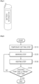
- FIG. 2 is a flowchart of a laser transmission characteristic value determination method according to an embodiment of the present invention.
- the laser frequency, the marking speed, and the focal distance are set to predetermined temporary setting values to mark a battery cell whose appearance is formed of a heat shrinkable tube (temporary setting step: S 110).
- a laser beam is transmitted with values set to predetermined temporary setting values to mark a letter on the heat shrinkable tube (marking step: S120), and apply heat (heating step: S130).
- font size checking step: S140 it is checked whether the font size of the letter marked on the heat shrinkable tube is equal to or larger than a preset font size. If the identified font size is greater than or equal to the preset font size, the transmission characteristic values of frequency, marking speed and focal distance for the size are stored in a separate storage space.
- the temporary setting step S110 is a step of setting the laser frequency, marking speed and focal distance to predetermined temporary setting values.
- the focal length is a value at which the size of the font size is adjusted, and the frequency and marking speed are values mutually set to a value at which the font depth is adjusted.
- the frequency is set to 20 kHz to 100 kHz
- the focal distance is set to 10 mm to 300 mm
- the marking speed is set to 50 mm/sec to 5000 mm/sec.
- the marking step S120 is a step of marking a letter on the heat shrinkable tube using the values set in the temporary setting step S110. More specifically, a letter is marked through a laser marking device set with transmission characteristic values set to the predetermined temporary setting values.
- letters may be marked on the heat shrinkable tube like the information recorded on the label during battery cell production, or only a part of the information may be marked thereon.
- the heating step S130 is a step of applying heat to the heat shrinkable tube, and the heat is applied according to a heating time and a heating temperature determined in the shrinkage checking step.
- shrinkage checking step the shrinkage of the heat shrinkable tube is checked (shrinkage checking step), and based on the identified shrinkage, the heating time and the heating temperature values applied to the heat shrinkable tube are readout in a separate storage space when the battery cell is manufactured (heating setting value readout step).
- the shrinkage checking step is a step of checking the shrinkage set for the heat shrinkable tube.
- the shrinkage checking step checks the set value according to the size and shape of each battery cell.
- the heating setting values readout step is a step of reading out the heating time and the heating temperature value applied to the heat shrinkable tube in a separate storage space based on the shrinkage determined in the shrinkage checking step. It checks the values applied to the heat shrinkable tube when manufacturing the battery cell, and also checks the thickness of the heat shrinkable tube.
- the heating temperature is set to 70 °C or more and 120 °C or less, and the heating time is set in inverse proportion to the temperature.
- shrinkage is generally from 50% to 80%, thickness is set from 0.05 mm to 0.5 mm, and heating temperature and heating time vary depending on shrinkage and thickness.
- the heat shrinkable tube may be heated using a hot air fan, a heat gun, or the like.
- the font size checking step S140 is a step of checking whether the font size of the letter marked on the heat shrinkable tube is equal to or larger than a preset font size after the heating step S130.
- the heat shrinkable tube shrinks to the battery cell body, and the letter marked on the heat shrinkable tube is also reduced to check whether the reduced letter is readable.
- the transmission characteristic values of the frequency, marking speed and focal distance set in the temporary setting step S110 are stored. If the font size of the identified letter is less than the preset font size, the marking step S120 is performed again by correcting the frequency, the marking speed, and the focal distance.
- the preset font size is set to a value of 6 points (2.1084 mm) or more.
- the focal length is corrected so that the letter size may be increased and the frequency and marking speed are adjusted according to the focal distance.
- the focal length is reduced to increase the letter size, accordingly, it increases the energy of the laser and decreases the frequency or marking speed so that the tube is not penetrated during laser marking.
- the laser transmission characteristic value determination method ensures accurate laser transmission characteristic values by marking a readout symbol formed with a predetermined number of lines on a shrinkable tube with a laser having arbitrary transmission characteristic values set, and after applying heat, by checking the number of lines of the readout symbol and adjusting the transmission characteristic value to identify the number of lines by a predetermined number.
- FIG. 3 is a flowchart of a laser transmission characteristic value determination method according to another embodiment of the present invention.
- the laser frequency, the marking speed, and the focal distance are set to predetermined temporary setting values to mark a battery pack whose appearance is formed of a heat shrinkable tube (temporary setting step: S210).
- a laser beam is transmitted with values set to predetermined temporary set values and the heat shrinkable tube is marked with at least one readout symbol consisting of a predetermined number of lines (marking step S220), and heat is applied (heating step S230).
- the transmission characteristic values of frequency, marking speed and focal distance for the size are stored in a separate storage space.
- the temporary setting step S210 is a step of setting the laser frequency, marking speed and focal distance to predetermined temporary setting values.
- the focal length is a value at which the size of the readout symbol is adjusted, and the frequency and marking speed are values mutually set to values at which the depth of the readout symbol is adjusted.
- the frequency is set to 20 kHz to 100 kHz
- the focal distance is set to 10 mm to 300 mm
- the marking speed is set to 50 mm/sec to 5000 mm/sec.
- the marking step S220 is a step of marking one or more readout symbols composed of a predetermined number of lines in the heat shrinkable tube using the value set in the temporary setting step S210. More specifically, the readout symbol is marked through the laser marking device set with the transmission characteristic value set to the predetermined temporary setting value.
- the readout symbol has a plurality of horizontal or vertical lines in a predetermined range (the size of the font in which the information of the battery cell is written).
- the heating step S230 is a step of applying heat to the heat shrinkable tube, and the heat is applied according to the heating time and the heating temperature determined in the shrinkage checking step.
- shrinkage checking step the shrinkage of the heat shrinkable tube is checked (shrinkage checking step), and based on the identified shrinkage, the heating time and the heating temperature values applied to the heat shrinkable tube are readout in a separate storage space when the battery cell is manufactured (heating setting value readout step).
- the shrinkage checking step is a step of checking the shrinkage preset in the heat shrinkable tube.
- the shrinkage checking step checks the set values according to the size and shape of each battery cell.
- the heating setting values readout step is a step of reading out the heating time and the heating temperature values applied to the heat shrinkable tube in a separate storage space based on the shrinkage determined in the shrinkage checking step. It checks the values applied to the heat shrinkable tube when manufacturing the battery cell, and also checks the thickness of the heat shrinkable tube.
- the heating temperature is set to 70 °C or more and 120 °C or less, and the heating time is set in inverse proportion to the temperature.
- shrinkage is generally from 50% to 80%, thickness is set from 0.05 mm to 0.5 mm, and heating temperature and heating time vary depending on shrinkage and thickness.
- the heat shrinkable tube may be heated using a hot air fan, a heat gun, or the like.
- the readout symbol checking step S240 is a step of checking whether the number of readout symbols marked on the heat shrinkable tube is identified as a predetermined number after the heating step S230.
- the heat shrinkable tube shrinks to the battery cell body, and the letter marked on the heat shrinkable tube is also reduced together to check whether the reduced letter is identifiable through the readout symbol.
- the frequency, marking speed, and focal length set in the temporary setting step 5210 are stored in a separate storage space. If the number of identified lines is less than or greater than the predetermined number, the marking step S220 is performed again by correcting the frequency, the marking speed, and the focal distance.
- the predetermined length of the preset line is set to 2.1 mm in one embodiment, but it is not limited thereto.
- the length of the line identified in the readout symbol checking step S240 is 2.5 mm, since it is greater than the predetermined length, the number of lines is checked.
- the marking step S220 is performed again after the focal length is reduced.
- the line length is 2.5mm
- the identified four lines are identified by checking the number of lines, if the number of markings in step S220 is four, the corresponding frequency and marking speed are correct. If the number of markings in the marking step (S220) is five, it is marked too deeply and is not correctly identified.
- the frequency and the marking speed are increased and the marking step S220 is performed again.
- the readout symbol may be formed such that the direction of the line is horizontal and/or vertical.
- a letter is marked together and the laser transmission characteristic value may be determined by the determination method.
- the battery cell according to this embodiment of the present invention may be configured including only a heat shrinkable tube onto which the information of the corresponding battery cell is put without a label on the case appearance where the electrode assembly is received, so that it reduces the cost of label production and shortens the process to enable rapid production.
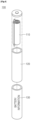
- FIG. 4 is a structural view of a battery cell according to this embodiment of the present invention.
- a battery cell 100 includes an electrode assembly 110 including an anode, a cathode, and a separator, an electrode assembly case 120 housing the electrode assembly, and an electrically insulating heat shrinkable tube 130 surrounding the outer periphery of the electrode assembly case excluding a portion where the electrode terminal or the external input/output terminal is formed.
- FIG. 4 shows a cylindrical shape, but the shape is not limited thereto.
- the electrode assembly 110 includes a cathode, and a separator.
- a positive electrode and a negative electrode, coated with an electrode active material, and a separator are stacked or wound in the order of an anode, a separator, and a cathode.
- the electrode assembly case 120 has a configuration for housing the electrode assembly, and may be formed of metal and may be formed in a rectangular shape as well as a cylindrical shape.
- the heat shrinkable tube 130 has an electrically insulating configuration surrounding an outer circumference of the electrode assembly case except for a portion where the electrode terminal or the external input/output terminal is formed and may be configured to surround not only one battery cell but also two or more battery cells.
- the heat shrinkable tube 130 has different shrinkage depending on the size and shape of the battery cell.
- the information on the battery cell is written on the surface of the heat shrinkable tube 130, and is marked by a laser marking device.
- the thickness of the heat shrinkable tube 130 is within 0.05 mm to 0.5 mm, so that information written on the surface of the battery cell may be marked, and the entire thickness is not allowed to be too thick.
- the battery cell may be produced quickly without any separate label configuration, and the cost of labeling is saved.
Landscapes
- Engineering & Computer Science (AREA)
- Physics & Mathematics (AREA)
- Optics & Photonics (AREA)
- Plasma & Fusion (AREA)
- Mechanical Engineering (AREA)
- Chemical & Material Sciences (AREA)
- Chemical Kinetics & Catalysis (AREA)
- Electrochemistry (AREA)
- General Chemical & Material Sciences (AREA)
- Sealing Battery Cases Or Jackets (AREA)
- Laser Beam Processing (AREA)
Description
- The present invention relates to a laser transmission characteristic value determination method, and more particularly, relates to a laser transmission characteristic value determination method for determining an appropriate transmission characteristic value of a laser so that a marked letter becomes a predetermined font size or more when marking a letter on a surface of a heat shrinkable tube formed on the outer periphery of a battery cell.
- The lithium secondary battery as a unit cell constituting the battery pack has flexibility, so that its shape is relatively free, its weight is light and its safety is excellent. Therefore, lithium secondary batteries are increasingly in demand for portable electronic devices such as mobile phones, camcorders and notebook computers.
- Also, the shape of the battery pack is divided according to the shape of the battery case. If the electrode assembly is embedded in a cylindrical or rectangular metal can, the shape of the battery pack is classified into a cylindrical battery pack and a prismatic battery pack. Also, when the electrode assembly is embedded in a pouch-shaped case of an aluminum laminate sheet, it is classified as a pouch type battery pack.
- Also, the electrode assembly included in the battery case is composed of an anode, a cathode, and a separator structure inserted between the anode and the cathode, and is chargeable/dischargeable. Also, the shape of the cylindrical electrode assembly is formed into a jelly-roll type in which a long sheet-like anode coated with an electrode active material, a separator and a cathode are sequentially stacked and wound.
- Meanwhile, in general, in order to express the certification logo of each country and the caution statement of the product, a separate PET label is attached to the battery cell, and such a conventional battery cell will be described with reference to
FIG. 1 . -
FIG. 1 is a structural view of a conventional battery cell. - Referring to
FIG. 1 , a conventional battery cell further includes a heat shrinkable tube for fixing the case and a label so that it may be insulated from the outside. - However, since the label does not have a function other than the letter delivery of the corresponding battery cell, unnecessary material costs are added.
- Therefore, it is required to develop a technology which may delete the unnecessary configuration while the product information of the battery cell is written.
- =Prior art document
DE 10 2015 006 837 A1 relates to a method of laser marking an item having a shrinkable material, wherein in a first step the shrinkable material is shrunk and in a second step the shrunk material is laser-marked. -
JP 2013-043 430 A - The object of the present invention is to provide a laser transmission characteristic value determination method for determining an appropriate laser transmission characteristic value, such that a label becomes unnecessary and the marking of a battery cell, instead of a label, takes place on a heat shrinkable tube.
- In accordance with the present invention this object is accomplished with a transmission characteristic value determination method with the features of claim 1 and with a method comprising the features of claim 7.
- Dependent claims are directed on features of preferred embodiments of the invention.
- Before the heating step, a shrinkage checking step of checking shrinkage of a heat shrinkable tube; and a heating setting value readout step of reading out a heating time and a heating temperature value applied to the heat shrinkable tube from a separate storage space when a battery cell is manufactured based on the shrinkage checked in the shrinkage checking step may be performed.
- The heating step is performed based on the heating time and the heating temperature value read out in the heating setting value readout step.
- The shrinkage of the heat shrinkable tube is set differently depending on a size and shape of a battery cell.
- When the font size of the letter identified in the font size checking step is less than the preset font size, the marking step is performed again by correcting a frequency, a marking speed, and a focal length.
- The preset font size may be set to a value of 6 points or more.
- In accordance with another exemplary embodiment, provided is a transmission characteristic value determination method of a laser marking a battery cell whose appearance is formed of a heat shrinkable tube, the method including: a temporary setting step of setting a frequency, a marking speed, and a focal distance of a laser to a predetermined temporary setting value; marking one or more readout symbols composed of a predetermined number of lines on the heat shrinkable tube by transmitting the laser using a temporary setting value set in the temporary setting step; a heating step of applying heat to the heat shrinkable tube; and a readout symbol checking step of checking, after the heating step, whether the number of readout symbols marked on the heat shrinkable tube is identified as a predetermined number and the length of the line is not less than a predetermined preset length, wherein when the length of the line identified in the readout symbol checking step is not less than the preset length and the number of lines is identified as the predetermined number, a transmission characteristic value storing step of storing the frequency, the marking speed, and the focal distance set in the temporary setting step in a separate storage space is performed.
- Before the heating step, a shrinkage checking step of checking shrinkage of a heat shrinkable tube; and a heating setting value readout step of reading out a heating time and a heating temperature value applied to the heat shrinkable tube from a separate storage space when a battery module is manufactured based on the shrinkage checked in the shrinkage checking step may be performed.
- The heating step is performed based on the heating time and the heating temperature value read out in the heating setting value readout step.
- The shrinkage of the heat shrinkable tube may be set differently depending on a size and shape of a battery cell.
- When the length of the line identified in the readout symbol checking step is less than the predetermined length or when the number of lines is less than or greater than the predetermined number, the marking step is performed again by correcting a frequency, a marking speed, and a focal length.
- A battery cell is disclosed, said battery cell includes: an electrode assembly including an anode, a cathode and a separator; an electrode assembly case for housing the electrode assembly; and an electrically insulating heat shrinkable tube for surrounding the outside of the electrode assembly case excluding a portion where the electrode terminal or the external input/output terminal is formed, and information of a corresponding cell is marked on the surface of the heat shrinkable tube.
- The information marked on the surface of the heat shrinkable tube may be marked through a laser marking device.
- The thickness of the heat shrinkable tube may be within 0.05 mm to 0.5 mm.
- In an embodiment of the present invention, in relation to the laser transmission characteristic value determination method, the proper transmission characteristic value of the laser is determined so that the letter of the battery cell may be written in a readable manner in the heat shrinkable tube and as the label configuration is deleted due to the information of the battery cell being written on the heat shrinkable tube with proper transmission characteristic value. Therefore, the incidental material cost due to the deleted label is reduced, thereby improving the economical efficiency.
-
-
FIG. 1 is a structural view of a conventional battery cell; -
FIG. 2 is a flowchart of a laser transmission characteristic value determination method according to an embodiment of the present invention; -
FIG. 3 is a flowchart of a laser transmission characteristic value determination method according to another embodiment of the present invention; and -
FIG. 4 is a structural view of a battery cell according to an embodiment of the present invention. - Hereinafter, exemplary embodiments of the present invention will be described in more detail with reference to the contents described in the accompanying drawings. However, the present invention is not limited or restricted to exemplary embodiments.
- Although the terms "first," "second," etc., may be used herein to describe various elements, these elements should not be limited by these terms. The above terms are used only to distinguish one component from another. For example, an initial component may be referred to as a second component and vice versa without departing from the scope of the present invention. Terms used in this specification are used to describe specific embodiments, and are not intended to limit the scope of the present invention. The singular expressions include plural expressions unless the context clearly dictates otherwise.
- Terms used in this specification may be currently widely used general terms in consideration of functions in the present invention but may vary according to the intents of those skilled in the art, precedents, or the advent of new technology. Additionally, in certain cases, there may be terms the applicant selects arbitrarily and in this case, their meanings are described in a corresponding description part of the present invention. Accordingly, terms used in the present invention should be defined based on the meaning of the term and the entire contents of the present invention instead of the simple term name.
- Next, a laser transmission characteristic value determination method according to an embodiment of the present invention will be described.
- The laser transmission characteristic value determination method according to an embodiment of the present invention marks a letter on a heat shrinkable tube with a laser with optional transmission characteristic values set, and after applying heat, checks the font size to adjust the transmission characteristic values to be the set font size. Therefore, it may increase the readability of the letter marked on the heat shrinkable tube so that the label configuration may be removed.
-
FIG. 2 is a flowchart of a laser transmission characteristic value determination method according to an embodiment of the present invention. - Referring to
FIG. 2 , in the laser transmission characteristic value determination method according to an embodiment of the present invention, the laser frequency, the marking speed, and the focal distance are set to predetermined temporary setting values to mark a battery cell whose appearance is formed of a heat shrinkable tube (temporary setting step: S 110). - Then, a laser beam is transmitted with values set to predetermined temporary setting values to mark a letter on the heat shrinkable tube (marking step: S120), and apply heat (heating step: S130).
- Then, it is checked whether the font size of the letter marked on the heat shrinkable tube is equal to or larger than a preset font size (font size checking step: S140). If the identified font size is greater than or equal to the preset font size, the transmission characteristic values of frequency, marking speed and focal distance for the size are stored in a separate storage space.
- Each step of the laser transmission characteristic value determination method is described in more detail below.
- The temporary setting step S110 is a step of setting the laser frequency, marking speed and focal distance to predetermined temporary setting values. The focal length is a value at which the size of the font size is adjusted, and the frequency and marking speed are values mutually set to a value at which the font depth is adjusted.
- Generally, the frequency is set to 20 kHz to 100 kHz, the focal distance is set to 10 mm to 300 mm, and the marking speed is set to 50 mm/sec to 5000 mm/sec.
- Also, the marking step S120 is a step of marking a letter on the heat shrinkable tube using the values set in the temporary setting step S110. More specifically, a letter is marked through a laser marking device set with transmission characteristic values set to the predetermined temporary setting values. Here, letters may be marked on the heat shrinkable tube like the information recorded on the label during battery cell production, or only a part of the information may be marked thereon.
- Also, the heating step S130 is a step of applying heat to the heat shrinkable tube, and the heat is applied according to a heating time and a heating temperature determined in the shrinkage checking step.
- Also, as using heat shrinkable tubes with different shrinkages depending on the size of the battery cells, before the heating step S130, the shrinkage of the heat shrinkable tube is checked (shrinkage checking step), and based on the identified shrinkage, the heating time and the heating temperature values applied to the heat shrinkable tube are readout in a separate storage space when the battery cell is manufactured (heating setting value readout step).
- The shrinkage checking step is a step of checking the shrinkage set for the heat shrinkable tube. The shrinkage checking step checks the set value according to the size and shape of each battery cell.
- The heating setting values readout step is a step of reading out the heating time and the heating temperature value applied to the heat shrinkable tube in a separate storage space based on the shrinkage determined in the shrinkage checking step. It checks the values applied to the heat shrinkable tube when manufacturing the battery cell, and also checks the thickness of the heat shrinkable tube.
- In general, the heating temperature is set to 70 °C or more and 120 °C or less, and the heating time is set in inverse proportion to the temperature. Also, shrinkage is generally from 50% to 80%, thickness is set from 0.05 mm to 0.5 mm, and heating temperature and heating time vary depending on shrinkage and thickness.
- These values are verified to enable transmission characteristic values of the laser to be applied to various heat shrinkable tubes.
- In addition, the heat shrinkable tube may be heated using a hot air fan, a heat gun, or the like.
- This is because, if heat is directly applied to the heat shrinkable tube, soot is generated, therefor indirect heat is applied to prevent the deterioration of the readability of the marked letter in the marking step S120.
- In addition, the font size checking step S140 is a step of checking whether the font size of the letter marked on the heat shrinkable tube is equal to or larger than a preset font size after the heating step S130. When manufacturing the battery cell, the heat shrinkable tube shrinks to the battery cell body, and the letter marked on the heat shrinkable tube is also reduced to check whether the reduced letter is readable.
- If the font size of the identified letter is greater than or equal to the preset font size, the transmission characteristic values of the frequency, marking speed and focal distance set in the temporary setting step S110 are stored. If the font size of the identified letter is less than the preset font size, the marking step S120 is performed again by correcting the frequency, the marking speed, and the focal distance. Here, the preset font size is set to a value of 6 points (2.1084 mm) or more.
- Also, when the frequency, the marking speed and the focal length are corrected, first, the focal length is corrected so that the letter size may be increased and the frequency and marking speed are adjusted according to the focal distance.
- For example, if the focal length is reduced to increase the letter size, accordingly, it increases the energy of the laser and decreases the frequency or marking speed so that the tube is not penetrated during laser marking.
- Next, a laser transmission characteristic value determination method according to another embodiment of the present invention will be described.
- The laser transmission characteristic value determination method according to another embodiment of the present invention ensures accurate laser transmission characteristic values by marking a readout symbol formed with a predetermined number of lines on a shrinkable tube with a laser having arbitrary transmission characteristic values set, and after applying heat, by checking the number of lines of the readout symbol and adjusting the transmission characteristic value to identify the number of lines by a predetermined number.
-
FIG. 3 is a flowchart of a laser transmission characteristic value determination method according to another embodiment of the present invention. - Referring to
FIG. 3 , in the laser transmission characteristic value determination method according to another embodiment of the present invention, the laser frequency, the marking speed, and the focal distance are set to predetermined temporary setting values to mark a battery pack whose appearance is formed of a heat shrinkable tube (temporary setting step: S210). - Then, a laser beam is transmitted with values set to predetermined temporary set values and the heat shrinkable tube is marked with at least one readout symbol consisting of a predetermined number of lines (marking step S220), and heat is applied (heating step S230).
- Then, it is checked whether or not the number of lines of the readout symbol marked on the heat shrinkable tube is identified as a predetermined number (font size checking step: S240). If the length of the identified line is greater than or equal to the predetermined length and the number of lines is identified as the predetermined number, the transmission characteristic values of frequency, marking speed and focal distance for the size are stored in a separate storage space.
- Each step of the laser transmission characteristic value determination method is described in more detail below.
- The temporary setting step S210 is a step of setting the laser frequency, marking speed and focal distance to predetermined temporary setting values. The focal length is a value at which the size of the readout symbol is adjusted, and the frequency and marking speed are values mutually set to values at which the depth of the readout symbol is adjusted.
- Generally, the frequency is set to 20 kHz to 100 kHz, the focal distance is set to 10 mm to 300 mm, and the marking speed is set to 50 mm/sec to 5000 mm/sec.
- Also, the marking step S220 is a step of marking one or more readout symbols composed of a predetermined number of lines in the heat shrinkable tube using the value set in the temporary setting step S210. More specifically, the readout symbol is marked through the laser marking device set with the transmission characteristic value set to the predetermined temporary setting value. Here, the readout symbol has a plurality of horizontal or vertical lines in a predetermined range (the size of the font in which the information of the battery cell is written).
- Also, the heating step S230 is a step of applying heat to the heat shrinkable tube, and the heat is applied according to the heating time and the heating temperature determined in the shrinkage checking step.
- Also, as using heat shrinkable tubes with different shrinkages depending on the size of the battery cells, before the heating step S230, the shrinkage of the heat shrinkable tube is checked (shrinkage checking step), and based on the identified shrinkage, the heating time and the heating temperature values applied to the heat shrinkable tube are readout in a separate storage space when the battery cell is manufactured (heating setting value readout step).
- The shrinkage checking step is a step of checking the shrinkage preset in the heat shrinkable tube. The shrinkage checking step checks the set values according to the size and shape of each battery cell.
- The heating setting values readout step is a step of reading out the heating time and the heating temperature values applied to the heat shrinkable tube in a separate storage space based on the shrinkage determined in the shrinkage checking step. It checks the values applied to the heat shrinkable tube when manufacturing the battery cell, and also checks the thickness of the heat shrinkable tube.
- In general, the heating temperature is set to 70 °C or more and 120 °C or less, and the heating time is set in inverse proportion to the temperature. Also, shrinkage is generally from 50% to 80%, thickness is set from 0.05 mm to 0.5 mm, and heating temperature and heating time vary depending on shrinkage and thickness.
- These values are verified to enable transmission characteristic values of the laser to be applied to various heat shrinkable tubes.
- In addition, the heat shrinkable tube may be heated using a hot air fan, a heat gun, or the like.
- This is because, if heat is directly applied to the heat shrinkable tube, soot is generated, therefor indirect heat is applied to prevent a deterioration of the readability of the marked readout symbol in the marking step S220.
- In addition, the readout symbol checking step S240 is a step of checking whether the number of readout symbols marked on the heat shrinkable tube is identified as a predetermined number after the heating step S230. When manufacturing a battery cell, the heat shrinkable tube shrinks to the battery cell body, and the letter marked on the heat shrinkable tube is also reduced together to check whether the reduced letter is identifiable through the readout symbol.
- If the length of a line in the readout symbol is equal to or greater than a preset length and the number of lines is identified as a predetermined number, the frequency, marking speed, and focal length set in the temporary setting step 5210 are stored in a separate storage space. If the number of identified lines is less than or greater than the predetermined number, the marking step S220 is performed again by correcting the frequency, the marking speed, and the focal distance. Here, the predetermined length of the preset line is set to 2.1 mm in one embodiment, but it is not limited thereto.
- For example, if the length of the line identified in the readout symbol checking step S240 is 2.5 mm, since it is greater than the predetermined length, the number of lines is checked.
- Also, if the length of the line identified in the readout symbol checking step S240 is 1.9 mm, since the focal length is less than the predetermined length value, the marking step S220 is performed again after the focal length is reduced.
- Also, when the value of the laser frequency or the marking speed is large, the heat shrinkable tube is penetrated, and when the value of the laser frequency or the marking speed is small, it is difficult to identify and the correct number of lines is not derived.
- For example, since the line length is 2.5mm, in a case where the identified four lines are identified by checking the number of lines, if the number of markings in step S220 is four, the corresponding frequency and marking speed are correct. If the number of markings in the marking step (S220) is five, it is marked too deeply and is not correctly identified.
- Thus, it re-performs the marking step S220 by decreasing the frequency and the marking speed.
- Also, if the number of markings in the marking step S220 is three, according to the difficulty of clear identification due to the low depth of the marked line, the frequency and the marking speed are increased and the marking step S220 is performed again.
- In addition, the readout symbol may be formed such that the direction of the line is horizontal and/or vertical. In addition, a letter is marked together and the laser transmission characteristic value may be determined by the determination method.
- Next, a battery cell according to another embodiment of the present invention will be described.
- The battery cell according to this embodiment of the present invention may be configured including only a heat shrinkable tube onto which the information of the corresponding battery cell is put without a label on the case appearance where the electrode assembly is received, so that it reduces the cost of label production and shortens the process to enable rapid production.
-
FIG. 4 is a structural view of a battery cell according to this embodiment of the present invention. - Referring to
FIG. 4 , abattery cell 100 according to an embodiment of the present invention includes anelectrode assembly 110 including an anode, a cathode, and a separator, anelectrode assembly case 120 housing the electrode assembly, and an electrically insulating heatshrinkable tube 130 surrounding the outer periphery of the electrode assembly case excluding a portion where the electrode terminal or the external input/output terminal is formed. Here,FIG. 4 shows a cylindrical shape, but the shape is not limited thereto. - Further, each configuration of the battery cell will be described in more detail below.
- The
electrode assembly 110 includes a cathode, and a separator. A positive electrode and a negative electrode, coated with an electrode active material, and a separator are stacked or wound in the order of an anode, a separator, and a cathode. - In addition, the
electrode assembly case 120 has a configuration for housing the electrode assembly, and may be formed of metal and may be formed in a rectangular shape as well as a cylindrical shape. - Also, the heat
shrinkable tube 130 has an electrically insulating configuration surrounding an outer circumference of the electrode assembly case except for a portion where the electrode terminal or the external input/output terminal is formed and may be configured to surround not only one battery cell but also two or more battery cells. - Also, the heat
shrinkable tube 130 has different shrinkage depending on the size and shape of the battery cell. - Also, the information on the battery cell is written on the surface of the heat
shrinkable tube 130, and is marked by a laser marking device. - Also, the thickness of the heat
shrinkable tube 130 is within 0.05 mm to 0.5 mm, so that information written on the surface of the battery cell may be marked, and the entire thickness is not allowed to be too thick. - Through this, the battery cell may be produced quickly without any separate label configuration, and the cost of labeling is saved.
- On the other hand, although the technical idea of the present invention is specifically described with reference to the above embodiments, it should be noted that the above embodiments are for the purpose of explanation and not for the purpose of limitation. It will be apparent to those skilled in the art that various modifications and variations may be made in the present invention without departing from the scope of the invention as defined in the claims.
-
- 100: Battery cell
- 110: Electrode assembly
- 120: Electrode assembly case
- 130: Heat shrinkable tube
Claims (11)
- A transmission characteristic value determination method of a laser marking a battery cell (100) whose appearance is formed of a heat shrinkable tube (130), the method comprising the following order of steps:first a temporary setting step (S110; S210) of setting a laser frequency to 20 kHz to 100 kHz, a marking speed to 50 mm/sec to 5000 mm/sec, and a focal distance of a laser to 10 mm to 300 mm which are predetermined temporary setting values, wherein the focal length is a value at which the size of the readout symbol is adjusted, and the frequency and the marking speed are values mutually set to a value at which the depth of the readout symbol is adjusted;then marking (S120; S220) a letter on the heat shrinkable tube (130) by transmitting the laser beam using temporary setting values set in the temporary setting step (S110; S210);then a heating step (S130; S230) of applying heat to the heat shrinkable tube (130) leading to a shrinkage of the tube (130); andthen a font size checking step (S140) of determining, after the heating step (S130; S230), whether a font size of the letter marked on the heat shrinkable tube (130) is greater than or equal to a preset font size,the method further comprising:
if the font size of the letter checked in the font size checking step (S140) is equal to or greater than a preset font size, a transmission characteristic value storing step of storing the frequency, the marking speed and the focal distance set in the temporary setting step (S110; S210) in a separate storage space, and if the font size of the letter is less than the preset font size, the marking step (S120; S220) being performed again by correcting the frequency, the marking speed and the focal distance. - The method of claim 1, wherein before the heating step (S130; S230) the following steps are performed: a shrinkage checking step of checking shrinkage of a heat shrinkable tube (130); and
based on the shrinkage checked in the shrinkage checking step a heating setting value readout step of reading out, from a separate storage space, a heating time and a heating temperature value applied to the heat shrinkable tube (130), when manufacturing a battery cell (100). - The method of claim 2, wherein the heating step (S130; S230) is performed based on the heating time and the heating temperature value read out in the heating setting value readout step.
- The method of claim 2, wherein the shrinkage of the heat shrinkable tube (130) is set in dependence on a size and shape of a battery cell (100).
- The method of claim 1, wherein if the font size of the letter identified in the font size checking step (S140) is less than the preset font size, the marking step (S120; S220) is performed again by correcting a frequency, a marking speed, and a focal length.
- The method of claim 5, wherein the preset font size is set to a value of 2.1084 mm or more.
- A transmission characteristic value determination method of a laser marking a battery cell (100) whose appearance is formed of a heat shrinkable tube (130), the method comprising the following order of steps:first a temporary setting step (S110; S210) of setting a laser frequency to 20 kHz to 100 kHz, a marking speed to 50 mm/sec to 5000 mm/sec, and a focal distance of a laser to 10 mm to 300 mm which are predetermined temporary setting values, wherein the focal length is a value at which the size of the readout symbol is adjusted, and the frequency and the marking speed are values mutually set to a value to which the depth of the readout symbol is adjusted;then marking (S120; S220) one or more readout symbols composed of a predetermined number of lines on the heat shrinkable tube (130) by transmitting the laser beam using temporary setting values set in the temporary setting step (S110; 5210);then a heating step (S130; S230) of applying heat to the heat shrinkable tube (130) leading to a shrinkage of the tube (130); andthen a readout symbol checking step of checking, after the heating step (S130; S230), whether the number of readout symbols marked on the heat shrinkable tube (130) is identified as a predetermined number and a length of the line is not less than a predetermined preset length,the method further comprising:
if the length of the line identified in the readout symbol checking step is not less than the preset length and the number of lines is identified as the predetermined number, a transmission characteristic value storing step of storing the frequency, the marking speed, and the focal distance set in the temporary setting step in a separate storage space, and if the length of the line identified in the readout checking step is less than a predetermined length value, the marking step (S220) being performed again after the focal length is reduced. - The method of claim 7, wherein before the heating step (S130; S230) the following steps are performed:a shrinkage checking step of checking shrinkage of a heat shrinkable tube (130); andbased on the shrinkage checked in the shrinkage checking step a heating setting value readout step of reading out, from a separate storage space, a heating time and a heating temperature value to be applied to the heat shrinkable tube (130), when manufacturing a battery cell (100).
- The method of claim 8, wherein the heating step is performed based on the heating time and the heating temperature values read out in the heating setting value readout step.
- The method of claim 8, wherein the shrinkage of the heat shrinkable tube (130) is set in dependence on a size and shape of a battery cell (100).
- The method of claim 7, wherein if the length of the line identified in the readout symbol checking step is less than the predetermined length or if the number of lines is less than or greater than the predetermined number, the marking step (S120; S220) is performed again by correcting a frequency, a marking speed, and a focal length.
Applications Claiming Priority (2)
| Application Number | Priority Date | Filing Date | Title |
|---|---|---|---|
| KR1020170122728A KR102409423B1 (en) | 2017-09-22 | 2017-09-22 | Method for determining emission characteristic value of laser |
| PCT/KR2018/010996 WO2019059617A1 (en) | 2017-09-22 | 2018-09-18 | Laser transmission characteristic value determination method |
Publications (3)
| Publication Number | Publication Date |
|---|---|
| EP3581322A1 EP3581322A1 (en) | 2019-12-18 |
| EP3581322A4 EP3581322A4 (en) | 2020-05-13 |
| EP3581322B1 true EP3581322B1 (en) | 2023-12-13 |
Family
ID=65811395
Family Applications (1)
| Application Number | Title | Priority Date | Filing Date |
|---|---|---|---|
| EP18859066.5A Active EP3581322B1 (en) | 2017-09-22 | 2018-09-18 | Laser transmission characteristic value determination method |
Country Status (8)
| Country | Link |
|---|---|
| US (1) | US11772197B2 (en) |
| EP (1) | EP3581322B1 (en) |
| JP (1) | JP7062156B2 (en) |
| KR (1) | KR102409423B1 (en) |
| CN (1) | CN110869160B (en) |
| ES (1) | ES2969550T3 (en) |
| HU (1) | HUE066058T2 (en) |
| WO (1) | WO2019059617A1 (en) |
Families Citing this family (2)
| Publication number | Priority date | Publication date | Assignee | Title |
|---|---|---|---|---|
| EP4143032B1 (en) * | 2020-04-30 | 2026-04-15 | Airnov, Inc. | Marking method, marking apparatus and marked receptacle |
| DE102020213776A1 (en) | 2020-11-03 | 2022-05-05 | Q.ant GmbH | Method of cleaving a crystal |
Citations (2)
| Publication number | Priority date | Publication date | Assignee | Title |
|---|---|---|---|---|
| US20060237878A1 (en) * | 2004-03-23 | 2006-10-26 | 3M Innovative Properties Company | Cold-shrink marker sleeve |
| CN205525730U (en) * | 2016-01-13 | 2016-08-31 | 兰州玖码电子科技有限公司 | Apply and beat target closing cap layer in bottle, pot shell pipe |
Family Cites Families (38)
| Publication number | Priority date | Publication date | Assignee | Title |
|---|---|---|---|---|
| JPH04101409A (en) | 1990-08-21 | 1992-04-02 | Elna Co Ltd | Electronic component marking method |
| JP2893996B2 (en) | 1991-05-27 | 1999-05-24 | 松下電器産業株式会社 | How to print on battery exterior |
| JP3438400B2 (en) | 1995-04-07 | 2003-08-18 | 松下電工株式会社 | Marking method for thermosetting resin |
| DE19727957A1 (en) * | 1996-07-02 | 1998-01-08 | Miyachi Technos Kk | Scanning laser marker |
| JPH1191250A (en) | 1997-09-19 | 1999-04-06 | Victor Co Of Japan Ltd | Heat shrinkable recording medium |
| US6495237B1 (en) * | 1998-09-29 | 2002-12-17 | Technolines Llc | Denim design from laser scribing |
| JP2000114619A (en) | 1998-10-06 | 2000-04-21 | Dainippon Printing Co Ltd | Laser marking device |
| JP3641248B2 (en) | 2002-04-11 | 2005-04-20 | 眞佐雄 北村 | Manufacturing method of wire instruction mark |
| SG149702A1 (en) * | 2002-12-16 | 2009-02-27 | Asml Netherlands Bv | Lithographic apparatus, device manufacturing method, and device manufactured thereby |
| KR20070041439A (en) * | 2004-05-18 | 2007-04-18 | 군제 가부시키가이샤 | Multilayer Heat Shrinkable Film and Packaging Battery |
| US8694148B2 (en) * | 2004-11-15 | 2014-04-08 | Electro Scientific Industries, Inc. | Tracking and marking specimens having defects formed during laser via drilling |
| KR100670473B1 (en) * | 2004-11-22 | 2007-01-16 | 삼성에스디아이 주식회사 | Battery pack can absorb and block electromagnetic waves |
| JP2006284536A (en) * | 2005-04-05 | 2006-10-19 | Dainippon Printing Co Ltd | Control mark position detection apparatus and control mark position detection method. |
| JP5194400B2 (en) * | 2006-01-05 | 2013-05-08 | 住友電気工業株式会社 | Ionomer resin composition and heat shrinkable tube using the same |
| KR20090081386A (en) * | 2006-10-13 | 2009-07-28 | 파나소닉 주식회사 | Battery Packs and Battery Mounted Devices |
| JP2008165095A (en) | 2006-12-29 | 2008-07-17 | Jig Engineering Co Ltd | Nameplate using heat-shrinkable tube |
| US8188178B2 (en) | 2007-05-07 | 2012-05-29 | 3M Innovative Properties Company | Cold shrinkable article including an epichlorohydrin composition |
| KR101305237B1 (en) | 2007-07-16 | 2013-09-06 | 주식회사 엘지화학 | Secondary Battery Comprising Battery Case with Outside Step |
| JP2009034691A (en) * | 2007-07-31 | 2009-02-19 | Cyber Laser Kk | Laser marking apparatus and method |
| JP2010023295A (en) | 2008-07-17 | 2010-02-04 | Fuji Seal International Inc | Heat shrinkable film for forming three-dimensional pattern, heat shrinkable cylindrical label, and three-dimensional pattern forming method of heat shrinkable film |
| KR101060879B1 (en) | 2008-10-31 | 2011-08-31 | 삼성전기주식회사 | Laser marking device |
| KR101720013B1 (en) * | 2009-01-27 | 2017-03-27 | 시즈오카켄 | Laser marking method |
| US8235695B2 (en) * | 2009-07-17 | 2012-08-07 | Nikon Corporation | Pattern forming device, pattern forming method, and device manufacturing method |
| KR101775738B1 (en) | 2009-08-31 | 2017-09-06 | 쓰리엠 이노베이티브 프로퍼티즈 컴파니 | Laser marking process and articles |
| US8212178B1 (en) * | 2009-09-28 | 2012-07-03 | Klein Tools, Inc. | Method and system for marking a material using a laser marking system |
| JP5614768B2 (en) | 2010-03-25 | 2014-10-29 | 株式会社日本製鋼所 | Laser processing apparatus and laser processing method |
| DE102010037273A1 (en) * | 2010-09-02 | 2012-03-08 | Schott Ag | Method and device for marking glass |
| JP6038889B2 (en) | 2011-05-02 | 2016-12-07 | アイピージー フォトニクス コーポレーション | Laser-based marking method and apparatus |
| TWI608886B (en) * | 2011-07-05 | 2017-12-21 | 電子科學工業股份有限公司 | Systems and methods for providing temperature stability of acousto-optic beam deflectors and acousto-optic modulators during use |
| JP2013043430A (en) | 2011-08-26 | 2013-03-04 | Seiko Instruments Inc | Thermal head, printer and marking method |
| CN105121173B (en) * | 2012-12-13 | 2017-10-27 | 角田新一郎 | Information writing film and sample storage body |
| KR101313646B1 (en) * | 2013-01-23 | 2013-10-02 | 제일엠텍(주) | Method for laser-marking on surface of resin article |
| JP2014162137A (en) | 2013-02-26 | 2014-09-08 | Denso Corp | Laser marking method and resin product |
| US9362535B2 (en) * | 2013-12-19 | 2016-06-07 | Ford Global Technologies, Llc | Pouch-type wrap for battery cell |
| KR101607842B1 (en) | 2014-12-19 | 2016-03-31 | 이노포토닉스 주식회사 | Marking system having correction function using pulse laser beam |
| JP5996687B2 (en) * | 2015-02-10 | 2016-09-21 | 浜松ホトニクス株式会社 | Inspection apparatus and inspection method |
| DE102015006837B4 (en) | 2015-06-02 | 2018-01-04 | Hellermann Tyton Gmbh | Method of execution with a device which is set up for a laser marking |
| CN106275670B (en) | 2015-06-24 | 2019-04-12 | 大族激光科技产业集团股份有限公司 | A kind of device that heat-shrink tube is marked using laser technology |
-
2017
- 2017-09-22 KR KR1020170122728A patent/KR102409423B1/en active Active
-
2018
- 2018-09-18 JP JP2019542214A patent/JP7062156B2/en active Active
- 2018-09-18 ES ES18859066T patent/ES2969550T3/en active Active
- 2018-09-18 EP EP18859066.5A patent/EP3581322B1/en active Active
- 2018-09-18 US US16/490,001 patent/US11772197B2/en active Active
- 2018-09-18 CN CN201880046296.7A patent/CN110869160B/en active Active
- 2018-09-18 WO PCT/KR2018/010996 patent/WO2019059617A1/en not_active Ceased
- 2018-09-18 HU HUE18859066A patent/HUE066058T2/en unknown
Patent Citations (2)
| Publication number | Priority date | Publication date | Assignee | Title |
|---|---|---|---|---|
| US20060237878A1 (en) * | 2004-03-23 | 2006-10-26 | 3M Innovative Properties Company | Cold-shrink marker sleeve |
| CN205525730U (en) * | 2016-01-13 | 2016-08-31 | 兰州玖码电子科技有限公司 | Apply and beat target closing cap layer in bottle, pot shell pipe |
Also Published As
| Publication number | Publication date |
|---|---|
| US11772197B2 (en) | 2023-10-03 |
| EP3581322A1 (en) | 2019-12-18 |
| KR102409423B1 (en) | 2022-06-16 |
| JP2020510957A (en) | 2020-04-09 |
| EP3581322A4 (en) | 2020-05-13 |
| CN110869160B (en) | 2021-12-14 |
| HUE066058T2 (en) | 2024-07-28 |
| US20190389006A1 (en) | 2019-12-26 |
| JP7062156B2 (en) | 2022-05-06 |
| WO2019059617A1 (en) | 2019-03-28 |
| ES2969550T3 (en) | 2024-05-21 |
| CN110869160A (en) | 2020-03-06 |
| KR20190033951A (en) | 2019-04-01 |
Similar Documents
| Publication | Publication Date | Title |
|---|---|---|
| KR101101079B1 (en) | Secondary battery | |
| US9660227B2 (en) | Sealing plate for prismatic secondary battery and prismatic secondary battery using the sealing plate | |
| US8252456B2 (en) | Battery outer label and battery provided with the same | |
| KR20130084086A (en) | Secondary battery | |
| US11772197B2 (en) | Laser transmission characteristic value determination method | |
| US9059460B2 (en) | Prismatic secondary battery | |
| KR20150134621A (en) | Flexible Battery Employed with a Plurality of Unit Cells | |
| US6716552B2 (en) | Secondary lithium battery construction for improved heat transfer | |
| KR102221808B1 (en) | Secondary battery | |
| US9620746B2 (en) | Secondary battery and manufacturing method thereof | |
| KR102234286B1 (en) | Curved secondary battery | |
| KR102914731B1 (en) | A coin cell battery and an electronic device comprising the same | |
| JP2000235845A (en) | Thin battery | |
| EP3561939B1 (en) | Battery pack | |
| KR20160139192A (en) | Battery Cell Including Separator Being Thermal Shrunk | |
| WO2020045873A1 (en) | Cylindrical battery and method of manufacturing same | |
| CN105579240B (en) | Method for printing the surface of a battery cell | |
| US20150270515A1 (en) | Secondary battery and manufacturing method for the same | |
| JP2015122191A (en) | Manufacturing method of power storage device, and constraint jig | |
| CN223651504U (en) | A battery cell and a battery cell module having the same. | |
| KR102697161B1 (en) | Battery pack and manufacturing method thereof | |
| KR100515836B1 (en) | Battery | |
| Jansen et al. | Flexible low-cost packaging for lithium ion batteries. |
Legal Events
| Date | Code | Title | Description |
|---|---|---|---|
| STAA | Information on the status of an ep patent application or granted ep patent |
Free format text: STATUS: THE INTERNATIONAL PUBLICATION HAS BEEN MADE |
|
| PUAI | Public reference made under article 153(3) epc to a published international application that has entered the european phase |
Free format text: ORIGINAL CODE: 0009012 |
|
| STAA | Information on the status of an ep patent application or granted ep patent |
Free format text: STATUS: REQUEST FOR EXAMINATION WAS MADE |
|
| 17P | Request for examination filed |
Effective date: 20190830 |
|
| AK | Designated contracting states |
Kind code of ref document: A1 Designated state(s): AL AT BE BG CH CY CZ DE DK EE ES FI FR GB GR HR HU IE IS IT LI LT LU LV MC MK MT NL NO PL PT RO RS SE SI SK SM TR |
|
| AX | Request for extension of the european patent |
Extension state: BA ME |
|
| A4 | Supplementary search report drawn up and despatched |
Effective date: 20200415 |
|
| RIC1 | Information provided on ipc code assigned before grant |
Ipc: B23K 26/359 20140101AFI20200407BHEP Ipc: B23K 26/02 20140101ALI20200407BHEP Ipc: B23K 26/00 20140101ALI20200407BHEP Ipc: B23K 103/00 20060101ALI20200407BHEP Ipc: B23K 26/352 20140101ALI20200407BHEP |
|
| DAV | Request for validation of the european patent (deleted) | ||
| DAX | Request for extension of the european patent (deleted) | ||
| RAP1 | Party data changed (applicant data changed or rights of an application transferred) |
Owner name: LG ENERGY SOLUTION LTD. |
|
| RAP3 | Party data changed (applicant data changed or rights of an application transferred) |
Owner name: LG ENERGY SOLUTION, LTD. |
|
| STAA | Information on the status of an ep patent application or granted ep patent |
Free format text: STATUS: EXAMINATION IS IN PROGRESS |
|
| 17Q | First examination report despatched |
Effective date: 20230224 |
|
| GRAP | Despatch of communication of intention to grant a patent |
Free format text: ORIGINAL CODE: EPIDOSNIGR1 |
|
| STAA | Information on the status of an ep patent application or granted ep patent |
Free format text: STATUS: GRANT OF PATENT IS INTENDED |
|
| INTG | Intention to grant announced |
Effective date: 20230706 |
|
| P01 | Opt-out of the competence of the unified patent court (upc) registered |
Effective date: 20230801 |
|
| GRAS | Grant fee paid |
Free format text: ORIGINAL CODE: EPIDOSNIGR3 |
|
| GRAA | (expected) grant |
Free format text: ORIGINAL CODE: 0009210 |
|
| STAA | Information on the status of an ep patent application or granted ep patent |
Free format text: STATUS: THE PATENT HAS BEEN GRANTED |
|
| AK | Designated contracting states |
Kind code of ref document: B1 Designated state(s): AL AT BE BG CH CY CZ DE DK EE ES FI FR GB GR HR HU IE IS IT LI LT LU LV MC MK MT NL NO PL PT RO RS SE SI SK SM TR |
|
| REG | Reference to a national code |
Ref country code: GB Ref legal event code: FG4D |
|
| REG | Reference to a national code |
Ref country code: CH Ref legal event code: EP |
|
| REG | Reference to a national code |
Ref country code: DE Ref legal event code: R096 Ref document number: 602018062729 Country of ref document: DE |
|
| REG | Reference to a national code |
Ref country code: IE Ref legal event code: FG4D |
|
| PG25 | Lapsed in a contracting state [announced via postgrant information from national office to epo] |
Ref country code: GR Free format text: LAPSE BECAUSE OF FAILURE TO SUBMIT A TRANSLATION OF THE DESCRIPTION OR TO PAY THE FEE WITHIN THE PRESCRIBED TIME-LIMIT Effective date: 20240314 |
|
| REG | Reference to a national code |
Ref country code: LT Ref legal event code: MG9D |
|
| PG25 | Lapsed in a contracting state [announced via postgrant information from national office to epo] |
Ref country code: LT Free format text: LAPSE BECAUSE OF FAILURE TO SUBMIT A TRANSLATION OF THE DESCRIPTION OR TO PAY THE FEE WITHIN THE PRESCRIBED TIME-LIMIT Effective date: 20231213 |
|
| REG | Reference to a national code |
Ref country code: NL Ref legal event code: MP Effective date: 20231213 |
|
| PG25 | Lapsed in a contracting state [announced via postgrant information from national office to epo] |
Ref country code: LT Free format text: LAPSE BECAUSE OF FAILURE TO SUBMIT A TRANSLATION OF THE DESCRIPTION OR TO PAY THE FEE WITHIN THE PRESCRIBED TIME-LIMIT Effective date: 20231213 Ref country code: GR Free format text: LAPSE BECAUSE OF FAILURE TO SUBMIT A TRANSLATION OF THE DESCRIPTION OR TO PAY THE FEE WITHIN THE PRESCRIBED TIME-LIMIT Effective date: 20240314 Ref country code: BG Free format text: LAPSE BECAUSE OF FAILURE TO SUBMIT A TRANSLATION OF THE DESCRIPTION OR TO PAY THE FEE WITHIN THE PRESCRIBED TIME-LIMIT Effective date: 20240313 |
|
| REG | Reference to a national code |
Ref country code: AT Ref legal event code: MK05 Ref document number: 1640085 Country of ref document: AT Kind code of ref document: T Effective date: 20231213 |
|
| PG25 | Lapsed in a contracting state [announced via postgrant information from national office to epo] |
Ref country code: NL Free format text: LAPSE BECAUSE OF FAILURE TO SUBMIT A TRANSLATION OF THE DESCRIPTION OR TO PAY THE FEE WITHIN THE PRESCRIBED TIME-LIMIT Effective date: 20231213 |
|
| REG | Reference to a national code |
Ref country code: ES Ref legal event code: FG2A Ref document number: 2969550 Country of ref document: ES Kind code of ref document: T3 Effective date: 20240521 |
|
| PG25 | Lapsed in a contracting state [announced via postgrant information from national office to epo] |
Ref country code: SE Free format text: LAPSE BECAUSE OF FAILURE TO SUBMIT A TRANSLATION OF THE DESCRIPTION OR TO PAY THE FEE WITHIN THE PRESCRIBED TIME-LIMIT Effective date: 20231213 Ref country code: RS Free format text: LAPSE BECAUSE OF FAILURE TO SUBMIT A TRANSLATION OF THE DESCRIPTION OR TO PAY THE FEE WITHIN THE PRESCRIBED TIME-LIMIT Effective date: 20231213 Ref country code: NO Free format text: LAPSE BECAUSE OF FAILURE TO SUBMIT A TRANSLATION OF THE DESCRIPTION OR TO PAY THE FEE WITHIN THE PRESCRIBED TIME-LIMIT Effective date: 20240313 Ref country code: NL Free format text: LAPSE BECAUSE OF FAILURE TO SUBMIT A TRANSLATION OF THE DESCRIPTION OR TO PAY THE FEE WITHIN THE PRESCRIBED TIME-LIMIT Effective date: 20231213 Ref country code: LV Free format text: LAPSE BECAUSE OF FAILURE TO SUBMIT A TRANSLATION OF THE DESCRIPTION OR TO PAY THE FEE WITHIN THE PRESCRIBED TIME-LIMIT Effective date: 20231213 Ref country code: HR Free format text: LAPSE BECAUSE OF FAILURE TO SUBMIT A TRANSLATION OF THE DESCRIPTION OR TO PAY THE FEE WITHIN THE PRESCRIBED TIME-LIMIT Effective date: 20231213 |
|
| PG25 | Lapsed in a contracting state [announced via postgrant information from national office to epo] |
Ref country code: IS Free format text: LAPSE BECAUSE OF FAILURE TO SUBMIT A TRANSLATION OF THE DESCRIPTION OR TO PAY THE FEE WITHIN THE PRESCRIBED TIME-LIMIT Effective date: 20240413 |
|
| PG25 | Lapsed in a contracting state [announced via postgrant information from national office to epo] |
Ref country code: AT Free format text: LAPSE BECAUSE OF FAILURE TO SUBMIT A TRANSLATION OF THE DESCRIPTION OR TO PAY THE FEE WITHIN THE PRESCRIBED TIME-LIMIT Effective date: 20231213 Ref country code: CZ Free format text: LAPSE BECAUSE OF FAILURE TO SUBMIT A TRANSLATION OF THE DESCRIPTION OR TO PAY THE FEE WITHIN THE PRESCRIBED TIME-LIMIT Effective date: 20231213 |
|
| REG | Reference to a national code |
Ref country code: HU Ref legal event code: AG4A Ref document number: E066058 Country of ref document: HU |
|
| PG25 | Lapsed in a contracting state [announced via postgrant information from national office to epo] |
Ref country code: SK Free format text: LAPSE BECAUSE OF FAILURE TO SUBMIT A TRANSLATION OF THE DESCRIPTION OR TO PAY THE FEE WITHIN THE PRESCRIBED TIME-LIMIT Effective date: 20231213 |
|
| PG25 | Lapsed in a contracting state [announced via postgrant information from national office to epo] |
Ref country code: SM Free format text: LAPSE BECAUSE OF FAILURE TO SUBMIT A TRANSLATION OF THE DESCRIPTION OR TO PAY THE FEE WITHIN THE PRESCRIBED TIME-LIMIT Effective date: 20231213 Ref country code: SK Free format text: LAPSE BECAUSE OF FAILURE TO SUBMIT A TRANSLATION OF THE DESCRIPTION OR TO PAY THE FEE WITHIN THE PRESCRIBED TIME-LIMIT Effective date: 20231213 Ref country code: RO Free format text: LAPSE BECAUSE OF FAILURE TO SUBMIT A TRANSLATION OF THE DESCRIPTION OR TO PAY THE FEE WITHIN THE PRESCRIBED TIME-LIMIT Effective date: 20231213 Ref country code: IT Free format text: LAPSE BECAUSE OF FAILURE TO SUBMIT A TRANSLATION OF THE DESCRIPTION OR TO PAY THE FEE WITHIN THE PRESCRIBED TIME-LIMIT Effective date: 20231213 Ref country code: IS Free format text: LAPSE BECAUSE OF FAILURE TO SUBMIT A TRANSLATION OF THE DESCRIPTION OR TO PAY THE FEE WITHIN THE PRESCRIBED TIME-LIMIT Effective date: 20240413 Ref country code: EE Free format text: LAPSE BECAUSE OF FAILURE TO SUBMIT A TRANSLATION OF THE DESCRIPTION OR TO PAY THE FEE WITHIN THE PRESCRIBED TIME-LIMIT Effective date: 20231213 Ref country code: CZ Free format text: LAPSE BECAUSE OF FAILURE TO SUBMIT A TRANSLATION OF THE DESCRIPTION OR TO PAY THE FEE WITHIN THE PRESCRIBED TIME-LIMIT Effective date: 20231213 Ref country code: AT Free format text: LAPSE BECAUSE OF FAILURE TO SUBMIT A TRANSLATION OF THE DESCRIPTION OR TO PAY THE FEE WITHIN THE PRESCRIBED TIME-LIMIT Effective date: 20231213 |
|
| PG25 | Lapsed in a contracting state [announced via postgrant information from national office to epo] |
Ref country code: PL Free format text: LAPSE BECAUSE OF FAILURE TO SUBMIT A TRANSLATION OF THE DESCRIPTION OR TO PAY THE FEE WITHIN THE PRESCRIBED TIME-LIMIT Effective date: 20231213 Ref country code: PT Free format text: LAPSE BECAUSE OF FAILURE TO SUBMIT A TRANSLATION OF THE DESCRIPTION OR TO PAY THE FEE WITHIN THE PRESCRIBED TIME-LIMIT Effective date: 20240415 |
|
| PG25 | Lapsed in a contracting state [announced via postgrant information from national office to epo] |
Ref country code: PT Free format text: LAPSE BECAUSE OF FAILURE TO SUBMIT A TRANSLATION OF THE DESCRIPTION OR TO PAY THE FEE WITHIN THE PRESCRIBED TIME-LIMIT Effective date: 20240415 Ref country code: PL Free format text: LAPSE BECAUSE OF FAILURE TO SUBMIT A TRANSLATION OF THE DESCRIPTION OR TO PAY THE FEE WITHIN THE PRESCRIBED TIME-LIMIT Effective date: 20231213 |
|
| REG | Reference to a national code |
Ref country code: DE Ref legal event code: R097 Ref document number: 602018062729 Country of ref document: DE |
|
| PG25 | Lapsed in a contracting state [announced via postgrant information from national office to epo] |
Ref country code: DK Free format text: LAPSE BECAUSE OF FAILURE TO SUBMIT A TRANSLATION OF THE DESCRIPTION OR TO PAY THE FEE WITHIN THE PRESCRIBED TIME-LIMIT Effective date: 20231213 |
|
| PLBE | No opposition filed within time limit |
Free format text: ORIGINAL CODE: 0009261 |
|
| STAA | Information on the status of an ep patent application or granted ep patent |
Free format text: STATUS: NO OPPOSITION FILED WITHIN TIME LIMIT |
|
| PG25 | Lapsed in a contracting state [announced via postgrant information from national office to epo] |
Ref country code: SI Free format text: LAPSE BECAUSE OF FAILURE TO SUBMIT A TRANSLATION OF THE DESCRIPTION OR TO PAY THE FEE WITHIN THE PRESCRIBED TIME-LIMIT Effective date: 20231213 |
|
| PG25 | Lapsed in a contracting state [announced via postgrant information from national office to epo] |
Ref country code: SI Free format text: LAPSE BECAUSE OF FAILURE TO SUBMIT A TRANSLATION OF THE DESCRIPTION OR TO PAY THE FEE WITHIN THE PRESCRIBED TIME-LIMIT Effective date: 20231213 Ref country code: DK Free format text: LAPSE BECAUSE OF FAILURE TO SUBMIT A TRANSLATION OF THE DESCRIPTION OR TO PAY THE FEE WITHIN THE PRESCRIBED TIME-LIMIT Effective date: 20231213 |
|
| 26N | No opposition filed |
Effective date: 20240916 |
|
| PG25 | Lapsed in a contracting state [announced via postgrant information from national office to epo] |
Ref country code: MC Free format text: LAPSE BECAUSE OF FAILURE TO SUBMIT A TRANSLATION OF THE DESCRIPTION OR TO PAY THE FEE WITHIN THE PRESCRIBED TIME-LIMIT Effective date: 20231213 |
|
| REG | Reference to a national code |
Ref country code: CH Ref legal event code: PL |
|
| PG25 | Lapsed in a contracting state [announced via postgrant information from national office to epo] |
Ref country code: LU Free format text: LAPSE BECAUSE OF NON-PAYMENT OF DUE FEES Effective date: 20240918 |
|
| PG25 | Lapsed in a contracting state [announced via postgrant information from national office to epo] |
Ref country code: CH Free format text: LAPSE BECAUSE OF NON-PAYMENT OF DUE FEES Effective date: 20240930 |
|
| PG25 | Lapsed in a contracting state [announced via postgrant information from national office to epo] |
Ref country code: IE Free format text: LAPSE BECAUSE OF NON-PAYMENT OF DUE FEES Effective date: 20240918 |
|
| PG25 | Lapsed in a contracting state [announced via postgrant information from national office to epo] |
Ref country code: FI Free format text: LAPSE BECAUSE OF FAILURE TO SUBMIT A TRANSLATION OF THE DESCRIPTION OR TO PAY THE FEE WITHIN THE PRESCRIBED TIME-LIMIT Effective date: 20231213 |
|
| PGFP | Annual fee paid to national office [announced via postgrant information from national office to epo] |
Ref country code: DE Payment date: 20250820 Year of fee payment: 8 |
|
| PGFP | Annual fee paid to national office [announced via postgrant information from national office to epo] |
Ref country code: BE Payment date: 20250820 Year of fee payment: 8 Ref country code: HU Payment date: 20250929 Year of fee payment: 8 Ref country code: GB Payment date: 20250820 Year of fee payment: 8 |
|
| PGFP | Annual fee paid to national office [announced via postgrant information from national office to epo] |
Ref country code: FR Payment date: 20250821 Year of fee payment: 8 |
|
| PG25 | Lapsed in a contracting state [announced via postgrant information from national office to epo] |
Ref country code: CY Free format text: LAPSE BECAUSE OF FAILURE TO SUBMIT A TRANSLATION OF THE DESCRIPTION OR TO PAY THE FEE WITHIN THE PRESCRIBED TIME-LIMIT; INVALID AB INITIO Effective date: 20180918 |
|
| PGFP | Annual fee paid to national office [announced via postgrant information from national office to epo] |
Ref country code: ES Payment date: 20251007 Year of fee payment: 8 |