EP3581152A1 - Platforms for mitral valve replacement - Google Patents
Platforms for mitral valve replacement Download PDFInfo
- Publication number
- EP3581152A1 EP3581152A1 EP19185264.9A EP19185264A EP3581152A1 EP 3581152 A1 EP3581152 A1 EP 3581152A1 EP 19185264 A EP19185264 A EP 19185264A EP 3581152 A1 EP3581152 A1 EP 3581152A1
- Authority
- EP
- European Patent Office
- Prior art keywords
- mitral
- mitral valve
- ring platform
- subject
- valved
- Prior art date
- Legal status (The legal status is an assumption and is not a legal conclusion. Google has not performed a legal analysis and makes no representation as to the accuracy of the status listed.)
- Granted
Links
Images





Classifications
-
- A—HUMAN NECESSITIES
- A61—MEDICAL OR VETERINARY SCIENCE; HYGIENE
- A61F—FILTERS IMPLANTABLE INTO BLOOD VESSELS; PROSTHESES; DEVICES PROVIDING PATENCY TO, OR PREVENTING COLLAPSING OF, TUBULAR STRUCTURES OF THE BODY, e.g. STENTS; ORTHOPAEDIC, NURSING OR CONTRACEPTIVE DEVICES; FOMENTATION; TREATMENT OR PROTECTION OF EYES OR EARS; BANDAGES, DRESSINGS OR ABSORBENT PADS; FIRST-AID KITS
- A61F2/00—Filters implantable into blood vessels; Prostheses, i.e. artificial substitutes or replacements for parts of the body; Appliances for connecting them with the body; Devices providing patency to, or preventing collapsing of, tubular structures of the body, e.g. stents
- A61F2/02—Prostheses implantable into the body
- A61F2/24—Heart valves ; Vascular valves, e.g. venous valves; Heart implants, e.g. passive devices for improving the function of the native valve or the heart muscle; Transmyocardial revascularisation [TMR] devices; Valves implantable in the body
- A61F2/2409—Support rings therefor, e.g. for connecting valves to tissue
-
- A—HUMAN NECESSITIES
- A61—MEDICAL OR VETERINARY SCIENCE; HYGIENE
- A61F—FILTERS IMPLANTABLE INTO BLOOD VESSELS; PROSTHESES; DEVICES PROVIDING PATENCY TO, OR PREVENTING COLLAPSING OF, TUBULAR STRUCTURES OF THE BODY, e.g. STENTS; ORTHOPAEDIC, NURSING OR CONTRACEPTIVE DEVICES; FOMENTATION; TREATMENT OR PROTECTION OF EYES OR EARS; BANDAGES, DRESSINGS OR ABSORBENT PADS; FIRST-AID KITS
- A61F2/00—Filters implantable into blood vessels; Prostheses, i.e. artificial substitutes or replacements for parts of the body; Appliances for connecting them with the body; Devices providing patency to, or preventing collapsing of, tubular structures of the body, e.g. stents
- A61F2/02—Prostheses implantable into the body
- A61F2/24—Heart valves ; Vascular valves, e.g. venous valves; Heart implants, e.g. passive devices for improving the function of the native valve or the heart muscle; Transmyocardial revascularisation [TMR] devices; Valves implantable in the body
- A61F2/2412—Heart valves ; Vascular valves, e.g. venous valves; Heart implants, e.g. passive devices for improving the function of the native valve or the heart muscle; Transmyocardial revascularisation [TMR] devices; Valves implantable in the body with soft flexible valve members, e.g. tissue valves shaped like natural valves
- A61F2/2418—Scaffolds therefor, e.g. support stents
-
- A—HUMAN NECESSITIES
- A61—MEDICAL OR VETERINARY SCIENCE; HYGIENE
- A61B—DIAGNOSIS; SURGERY; IDENTIFICATION
- A61B17/00—Surgical instruments, devices or methods
- A61B17/0057—Implements for plugging an opening in the wall of a hollow or tubular organ, e.g. for sealing a vessel puncture or closing a cardiac septal defect
- A61B2017/00575—Implements for plugging an opening in the wall of a hollow or tubular organ, e.g. for sealing a vessel puncture or closing a cardiac septal defect for closure at remote site, e.g. closing atrial septum defects
-
- A—HUMAN NECESSITIES
- A61—MEDICAL OR VETERINARY SCIENCE; HYGIENE
- A61B—DIAGNOSIS; SURGERY; IDENTIFICATION
- A61B17/00—Surgical instruments, devices or methods
- A61B17/0057—Implements for plugging an opening in the wall of a hollow or tubular organ, e.g. for sealing a vessel puncture or closing a cardiac septal defect
- A61B2017/00575—Implements for plugging an opening in the wall of a hollow or tubular organ, e.g. for sealing a vessel puncture or closing a cardiac septal defect for closure at remote site, e.g. closing atrial septum defects
- A61B2017/00606—Implements H-shaped in cross-section, i.e. with occluders on both sides of the opening
-
- A—HUMAN NECESSITIES
- A61—MEDICAL OR VETERINARY SCIENCE; HYGIENE
- A61B—DIAGNOSIS; SURGERY; IDENTIFICATION
- A61B17/00—Surgical instruments, devices or methods
- A61B2017/00831—Material properties
- A61B2017/00867—Material properties shape memory effect
-
- A—HUMAN NECESSITIES
- A61—MEDICAL OR VETERINARY SCIENCE; HYGIENE
- A61F—FILTERS IMPLANTABLE INTO BLOOD VESSELS; PROSTHESES; DEVICES PROVIDING PATENCY TO, OR PREVENTING COLLAPSING OF, TUBULAR STRUCTURES OF THE BODY, e.g. STENTS; ORTHOPAEDIC, NURSING OR CONTRACEPTIVE DEVICES; FOMENTATION; TREATMENT OR PROTECTION OF EYES OR EARS; BANDAGES, DRESSINGS OR ABSORBENT PADS; FIRST-AID KITS
- A61F2/00—Filters implantable into blood vessels; Prostheses, i.e. artificial substitutes or replacements for parts of the body; Appliances for connecting them with the body; Devices providing patency to, or preventing collapsing of, tubular structures of the body, e.g. stents
- A61F2/02—Prostheses implantable into the body
- A61F2/24—Heart valves ; Vascular valves, e.g. venous valves; Heart implants, e.g. passive devices for improving the function of the native valve or the heart muscle; Transmyocardial revascularisation [TMR] devices; Valves implantable in the body
- A61F2/2427—Devices for manipulating or deploying heart valves during implantation
- A61F2/2436—Deployment by retracting a sheath
-
- A—HUMAN NECESSITIES
- A61—MEDICAL OR VETERINARY SCIENCE; HYGIENE
- A61F—FILTERS IMPLANTABLE INTO BLOOD VESSELS; PROSTHESES; DEVICES PROVIDING PATENCY TO, OR PREVENTING COLLAPSING OF, TUBULAR STRUCTURES OF THE BODY, e.g. STENTS; ORTHOPAEDIC, NURSING OR CONTRACEPTIVE DEVICES; FOMENTATION; TREATMENT OR PROTECTION OF EYES OR EARS; BANDAGES, DRESSINGS OR ABSORBENT PADS; FIRST-AID KITS
- A61F2/00—Filters implantable into blood vessels; Prostheses, i.e. artificial substitutes or replacements for parts of the body; Appliances for connecting them with the body; Devices providing patency to, or preventing collapsing of, tubular structures of the body, e.g. stents
- A61F2/02—Prostheses implantable into the body
- A61F2/24—Heart valves ; Vascular valves, e.g. venous valves; Heart implants, e.g. passive devices for improving the function of the native valve or the heart muscle; Transmyocardial revascularisation [TMR] devices; Valves implantable in the body
- A61F2/2442—Annuloplasty rings or inserts for correcting the valve shape; Implants for improving the function of a native heart valve
- A61F2/2445—Annuloplasty rings in direct contact with the valve annulus
-
- A—HUMAN NECESSITIES
- A61—MEDICAL OR VETERINARY SCIENCE; HYGIENE
- A61F—FILTERS IMPLANTABLE INTO BLOOD VESSELS; PROSTHESES; DEVICES PROVIDING PATENCY TO, OR PREVENTING COLLAPSING OF, TUBULAR STRUCTURES OF THE BODY, e.g. STENTS; ORTHOPAEDIC, NURSING OR CONTRACEPTIVE DEVICES; FOMENTATION; TREATMENT OR PROTECTION OF EYES OR EARS; BANDAGES, DRESSINGS OR ABSORBENT PADS; FIRST-AID KITS
- A61F2210/00—Particular material properties of prostheses classified in groups A61F2/00 - A61F2/26 or A61F2/82 or A61F9/00 or A61F11/00 or subgroups thereof
- A61F2210/009—Particular material properties of prostheses classified in groups A61F2/00 - A61F2/26 or A61F2/82 or A61F9/00 or A61F11/00 or subgroups thereof magnetic
-
- A—HUMAN NECESSITIES
- A61—MEDICAL OR VETERINARY SCIENCE; HYGIENE
- A61F—FILTERS IMPLANTABLE INTO BLOOD VESSELS; PROSTHESES; DEVICES PROVIDING PATENCY TO, OR PREVENTING COLLAPSING OF, TUBULAR STRUCTURES OF THE BODY, e.g. STENTS; ORTHOPAEDIC, NURSING OR CONTRACEPTIVE DEVICES; FOMENTATION; TREATMENT OR PROTECTION OF EYES OR EARS; BANDAGES, DRESSINGS OR ABSORBENT PADS; FIRST-AID KITS
- A61F2220/00—Fixations or connections for prostheses classified in groups A61F2/00 - A61F2/26 or A61F2/82 or A61F9/00 or A61F11/00 or subgroups thereof
- A61F2220/0025—Connections or couplings between prosthetic parts, e.g. between modular parts; Connecting elements
-
- A—HUMAN NECESSITIES
- A61—MEDICAL OR VETERINARY SCIENCE; HYGIENE
- A61F—FILTERS IMPLANTABLE INTO BLOOD VESSELS; PROSTHESES; DEVICES PROVIDING PATENCY TO, OR PREVENTING COLLAPSING OF, TUBULAR STRUCTURES OF THE BODY, e.g. STENTS; ORTHOPAEDIC, NURSING OR CONTRACEPTIVE DEVICES; FOMENTATION; TREATMENT OR PROTECTION OF EYES OR EARS; BANDAGES, DRESSINGS OR ABSORBENT PADS; FIRST-AID KITS
- A61F2230/00—Geometry of prostheses classified in groups A61F2/00 - A61F2/26 or A61F2/82 or A61F9/00 or A61F11/00 or subgroups thereof
- A61F2230/0063—Three-dimensional shapes
- A61F2230/0095—Saddle-shaped
-
- A—HUMAN NECESSITIES
- A61—MEDICAL OR VETERINARY SCIENCE; HYGIENE
- A61F—FILTERS IMPLANTABLE INTO BLOOD VESSELS; PROSTHESES; DEVICES PROVIDING PATENCY TO, OR PREVENTING COLLAPSING OF, TUBULAR STRUCTURES OF THE BODY, e.g. STENTS; ORTHOPAEDIC, NURSING OR CONTRACEPTIVE DEVICES; FOMENTATION; TREATMENT OR PROTECTION OF EYES OR EARS; BANDAGES, DRESSINGS OR ABSORBENT PADS; FIRST-AID KITS
- A61F2250/00—Special features of prostheses classified in groups A61F2/00 - A61F2/26 or A61F2/82 or A61F9/00 or A61F11/00 or subgroups thereof
- A61F2250/0058—Additional features; Implant or prostheses properties not otherwise provided for
- A61F2250/006—Additional features; Implant or prostheses properties not otherwise provided for modular
Definitions
- the present invention relates to mitral valve prosthetic devices and, more particularly, to platforms into which mitral valve prosthetic devices may be deployed percutaneously and/or transapically.
- TMVI Transcatheter Mitral Valve Implantation
- CVT CardiAQ Valve Technologies
- a third known minimally invasive off pump mitral valve replacement device is being developed by Georg Lutter's group at the University of Kiel in Germany. Their design is stent based but requires placement through the apex of the left ventricle (LV). Surgically manipulating the LV apex through a small incision can be relatively dangerous particularly in patients with CHF and IMR. This is a relative negative for that design as it is more desirable to access the mitral valve via the safer and more forgiving lower pressure left atrium.
- the anchoring mechanism is also awkward in that it relies on a chord from the implant being brought out through the LV apical incision and secured in the closure of that incision. This anchoring strategy also precludes the device ever evolving to the point of being placed via a peripheral blood vessel.
- the mitral valve replacement platforms described herein are designed to assist patients who suffer from ischemic mitral valve regurgitation (IMR).
- IMR ischemic mitral valve regurgitation
- the majority of patients with IMR would benefit from valve replacement but are too sick to withstand the morbidity of standard valve replacement procedures.
- This population of patients in the United States alone is estimated to be 1.2 to 2.1 million patients, with approximately 425,000 patients having moderate or severe IMR with heart failure.
- IMR results from left ventricular (LV) distortions caused by a myocardial infarction (MI) or heart attack. Patients with this disease survive their heart attack but the resulting injury causes the ventricle to dilate and fail over months and years.
- this congestive heart failure (CHF) is worsened by IMR. Patients with CHF and IMR can become extremely sick and be very hard to manage medically.
- Most clinicians agree that a competent mitral valve would make the management of these patients much more straightforward and cost effective.
- a mitral valve prosthesis that is percutaneously and/or transapically deployed in at least two stages.
- a mitral annular platform adapted for percutaneous and/or transapical delivery is delivered to and anchored in the mitral valve annulus.
- a valved-stent mitral valve prosthetic device adapted for percutaneously and/or transapical delivery is delivered to the mitral valve annulus for mounting in the mitral annular ring platform.
- the mitral annular platform includes a plurality of wires preformed into separate but contiguous helices. At least one of the helices is adapted to serve as an anchor on the atrial side of the mitral annulus, and at least one of the helices is adapted to serve as an anchor on the ventricular side of the mitral annulus. At least one of the helices traverses the mitral annulus, connecting the atrial and mitral helices to each other. In total, the helices combine to serve as a landing zone for subsequent percutaneous valved-stent implantation.
- the mitral annular platform is anchored to the atrial septum.
- Left and right discs straddle the atrial septum and have a central hollow region therebetween so as to allow left atrial access from the right atrium when the discs are deployed in a heart.
- the mitral annular ring platform includes at least one disc adapted to fit into the mitral valve annulus.
- a mitral annular ring adapted to be implanted in an atrial septum is deployed across a mitral valve orifice and to accept the valved-stent mitral valve prosthesis. Once a valved-stent device is implanted into the mitral annular ring, a plug is deployed to close the hollow central region between the left and right atrial discs.
- the mitral annular platform includes a first magnetic ring having a first polarity and adapted for placement in a left atrium in a supra mitral annular position via a patient's femoral (jugular, or subclavian) vein, and a second magnetic ring having a second polarity and adapted for placement on a ventricular side of the mitral annulus via a femoral artery and/or transapically (from the LV apex).
- the first and second magnetic rings are brought together to lock together magnetically so as to sandwich mitral valve tissue and mitral annulus circumferentially when deployed.
- the mitral annular platform includes a first petal-shaped wire ring having a hollow center and adapted for placement on an atrial side of the mitral annulus so as to exert downward pressure, and a second petal-shaped wire ring having a hollow center and adapted for placement on a ventricular side of the metal annulus so as to exert upward pressure.
- the first and second petal-shaped wire rings overlap in central region thereof to apply opposing pressures.
- the mitral valve annulus is non-uniform, non-planar, dynamic structure. Percutaneously anchoring a replacement valve securely in this location in the absence of a surgically placed annuloplasty ring remains a significant challenge.
- the embodiments described below were designed to permit the percutaneous and/or transapical stepwise construction of a platform or "landing zone" in the mitral space to facilitate subsequent implantation of a percutaneously placed replacement valve.
- the designs vary but are linked by the overarching concept of a percutaneous and/or transapical platform construction to facilitate percutaneous mitral valve device anchoring and perivalvular seal.
- the advantage to these approaches to "landing zone" construction is that each can be performed percutaneously and/or transapically without need for a large incision or cardiopulmonary bypass.
- a successful percutaneously and/or transapically placed mitral valve requires four major design characteristics:
- a single, thick nitinol wire is preformed into three separate but contiguous helices that are inserted percutaneously and/or transapically to provide a "landing zone" or anchoring mechanism to facilitate the placement of simple valved stents in the mitral position.
- the leading helix has 1 to 2 coils and is large enough in diameter to serve as the left ventricular anchor for the valve.
- the second helix is comprised of at least one but potentially as many as 5 to 6 more tightly wound coils of a smaller diameter that are designed to fit snuggly in the annulus.
- This part of the coil may be coated with a bi-layer material composed of a super absorbent substance that expands when the valve is in place to prevent perivalvular leakage.
- the outer layer of the bi-layer is a hydrophobic material that prevents the super absorbent material from expanding while the valve is being placed.
- This second layer is designed to elute off slowly to ultimately allow the underlying superabsorbent material to expand once the valve is positioned appropriately.
- the inter-annular portion of the coil also may be fitted with a bioprosthetic valve leaflet material that folds into a functional valve mechanism when the device assumes its coiled position.
- the last helix is similar to the first and serves as the atrial anchoring mechanism. When locked into position, the mitral annulus is "sandwiched" between the leading and trailing helices, with the valve leaflets centrally positioned in the annulus.
- the helical coil design of this embodiment also may be adapted to provide a "landing zone" or anchoring mechanism to facilitate the placement of simple valved stents (like the ones currently being placed clinically in the aortic and pulmonary position, as shown in Figure 1 ) in the mitral position as shown in Figure 3 .
- the landing zone is deployed as illustrated in Figure 2 and a valved stent is placed in the landing zone as shown in Figure 3 .
- the inter-annular portion of the coil is not fitted with valve leaflet material.
- This embodiment also can be adapted to create a catheter based reduction annuloplasty device to decrease annular area and reduce mitral regurgitation as shown in Figure 4 .
- the valved helical design of this embodiment has the potential to decrease catheter delivery size for percutaneous and/or transapical valve replacement to almost unimaginably small diameters.
- the helical anchoring platform also allows placement of currently available stented valves, designed for placement in the aortic and pulmonary positions, to be placed in the mitral position.
- An annuloplasty ring formed from the helices also may potentially provide a non-invasive means to limit MR when valve placement is contra-indicated.
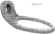
- a nitinol based device is anchored to the atrial septum that is preformed into a complex 3D shape ( Figure 5A ) including left and right atrial discs (e.g. 0.012 inch nitinol donut) that straddle the atrial septum, a central hollow region between the discs to allow for easy left atrial access from the right atrium, and a mitral annular ring-shaped or oval shaped platform designed to lay across the mitral valve orifice.
- the mitral annular ring platform includes at least one of the discs adapted to fit into the mitral valve annulus.
- the nitinol device may be compressed for percutaneous and/or transapical delivery. Once in position, a valve-stented device can be passed from the femoral vein, across the atrial septum, and into the mitral annular ring where the device is anchored to the atrial septum.
- the device of Figures 5A and 5B is implanted into the atrial septum using standard percutaneous and/or transapical transeptal techniques.
- a transeptal delivery catheter is guided into the left atrium as shown in Figure 6 .
- a delivery sheath e . g . 12-16 French
- the compressed device of Figure 5A is then guided through the delivery catheter for deployment in the left atrium as shown in Figure 8 .
- the device of Figure 5A is released from its deployment cable as shown in Figure 9 .
- a valved-stent device can be passed over a guide wire from the femoral vein, across the atrial septum, and into the mitral annular ring as shown in Figure 10 and 11 .
- the hollow portion of the ASAMP device is plugged using a custom designed nitinol plug as shown in Figure 12 .
- two magnetized rings with opposite magnetizations are deployed such that the first ring is positioned in the left atrium in the supra-mitral annular position via the femoral (jugular or subclavian) vein using a standard transeptal approach and the second ring is positioned on the ventricular side of the mitral annulus via a retrograde arterial approach (femoral artery, aorta, aortic valve, left ventricle) as shown in Figure 13 .
- the rings are fully formed in their respective positions, they are brought together using their respective delivery catheters and are locked together by the magnetic attraction of the rings so as to sandwich the mitral valve tissue and annulus circumferentially as shown in Figure 14 .
- both rings are released from their delivery catheters.
- a valve-stented device can be passed from the femoral vein, across the atrial septum, and into the mitral annular ring as shown in Figure 15 .
- two petal-shaped wire rings ( Figure 16 ) that are joined together and hollow in the center are deployed such that the first ring is on the atrial side of the annulus so as to exert a downward pressure and the second ring is on the ventricular side of the annulus so as to exert a counterpressure (upward) to the first ring as shown in Figure 17 .
- the rings together sandwich the mitral valve tissue and annulus circumferentially. Once in position, a valve-stented device can be passed from the femoral vein, across the atrial septum, and into the mitral annular ring platform as shown in Figure 18 .
- the present invention also relates to the following items:
Landscapes
- Health & Medical Sciences (AREA)
- Engineering & Computer Science (AREA)
- Biomedical Technology (AREA)
- Cardiology (AREA)
- Oral & Maxillofacial Surgery (AREA)
- Transplantation (AREA)
- Heart & Thoracic Surgery (AREA)
- Vascular Medicine (AREA)
- Life Sciences & Earth Sciences (AREA)
- Animal Behavior & Ethology (AREA)
- General Health & Medical Sciences (AREA)
- Public Health (AREA)
- Veterinary Medicine (AREA)
- Prostheses (AREA)
Abstract
Description
- The present application claim priority to
U.S. Provisional Patent Application No. 61/578,382, filed December 21, 2011 - The present invention relates to mitral valve prosthetic devices and, more particularly, to platforms into which mitral valve prosthetic devices may be deployed percutaneously and/or transapically.
- The use of a catheter based percutaneous valved stent has been shown to be feasible in replacing both the human pulmonic and aortic valves. The pulmonic valve was the first to be successfully replaced by a percutaneous approach and is the furthest along in development (
Figure 1A ). There are currently two aortic valve products in clinical trials (Figure 1B and Figure 1C ) and more in development that are deployed percutaneously. While there is a great deal of interest in replacing the mitral valve percutaneously, the anatomy and function of the mitral valve prevents direct application of the current aortic/pulmonic technology. - In addition to the percutaneous catheter-based aortic valve replacement devices illustrated in
Figure 1 , there are three other types of replacement valve prosthesis known to the applicants that use different technologies. One known technology, named the Transcatheter Mitral Valve Implantation (TMVI), is being developed by CardiAQ Valve Technologies (CVT). This design is more of a basic stent which lacks a sufficient anchoring mechanism. The TMVI is in a very preliminary design phase and, to date, has not been tested repeatedly with success in animal models. A second known technology is being developed by EndoValve. The EndoValve design is not stent based but relies on a tripod anchoring system with a central supporting strut. A device to be used with this technology will be introduced by minimally invasive surgical techniques. A third known minimally invasive off pump mitral valve replacement device is being developed by Georg Lutter's group at the University of Kiel in Germany. Their design is stent based but requires placement through the apex of the left ventricle (LV). Surgically manipulating the LV apex through a small incision can be relatively dangerous particularly in patients with CHF and IMR. This is a relative negative for that design as it is more desirable to access the mitral valve via the safer and more forgiving lower pressure left atrium. The anchoring mechanism is also awkward in that it relies on a chord from the implant being brought out through the LV apical incision and secured in the closure of that incision. This anchoring strategy also precludes the device ever evolving to the point of being placed via a peripheral blood vessel. - There are also a large group of percutaneous mitral valve repair devices that have been developed to date. The majority of these devices have tried to exploit the proximity of the coronary sinus to the mitral valve annulus to perform some type of "annuloplasty" to limit mitral regurgitation. The basic premise behind all of them is to place a device in the coronary sinus that will shrink the valve orifice and thus decrease mitral regurgitation. However, none of these techniques has shown reproducible efficacy in human trials despite almost 10 years of development work. The most successful percutaneous mitral valve repair technique is EValve's MitraClip® System. This device is used to clip the mitral leaflets together to limit mitral regurgitation. Unfortunately, the clip system has significant down sides. It can be very difficult and tedious to master technically and even in expert hands can take hours to place. Also, it does not eliminate MR; it only limits it. It does not approximate the success of surgical mitral valve repair or replacement and as such is only a temporizing strategy.
- The mitral valve replacement platforms described herein are designed to assist patients who suffer from ischemic mitral valve regurgitation (IMR). The majority of patients with IMR would benefit from valve replacement but are too sick to withstand the morbidity of standard valve replacement procedures. This population of patients in the United States alone is estimated to be 1.2 to 2.1 million patients, with approximately 425,000 patients having moderate or severe IMR with heart failure. IMR results from left ventricular (LV) distortions caused by a myocardial infarction (MI) or heart attack. Patients with this disease survive their heart attack but the resulting injury causes the ventricle to dilate and fail over months and years. In many cases this congestive heart failure (CHF) is worsened by IMR. Patients with CHF and IMR can become extremely sick and be very hard to manage medically. Most clinicians agree that a competent mitral valve would make the management of these patients much more straightforward and cost effective.
- Accordingly, there is a significant need for percutaneous mitral valve replacement technologies that are appropriately configured to account for the dimensions and geometry of the mitral valve. It would be advantageous to have a device that can be deployed percutaneously and/or transapically to create a platform at the mitral valve position that reduces the diameter to an appropriate and uniform size/dimension for subsequent percutaneous and/or transapical implantation of a valved-stent. The invention provides several embodiments of such a device.
- The present inventors have addressed the above needs in the art by providing a mitral valve prosthesis that is percutaneously and/or transapically deployed in at least two stages. In a first stage, a mitral annular platform adapted for percutaneous and/or transapical delivery is delivered to and anchored in the mitral valve annulus. In the second stage, a valved-stent mitral valve prosthetic device adapted for percutaneously and/or transapical delivery is delivered to the mitral valve annulus for mounting in the mitral annular ring platform. This approach provides a consistent platform for accepting valved-stent mitral valve prosthetic devices from different vendors to be used.
- Several embodiments of the mitral annular platform are provided in accordance with the invention.
- In a first embodiment, the mitral annular platform includes a plurality of wires preformed into separate but contiguous helices. At least one of the helices is adapted to serve as an anchor on the atrial side of the mitral annulus, and at least one of the helices is adapted to serve as an anchor on the ventricular side of the mitral annulus. At least one of the helices traverses the mitral annulus, connecting the atrial and mitral helices to each other. In total, the helices combine to serve as a landing zone for subsequent percutaneous valved-stent implantation.
- In a second embodiment, the mitral annular platform is anchored to the atrial septum. Left and right discs straddle the atrial septum and have a central hollow region therebetween so as to allow left atrial access from the right atrium when the discs are deployed in a heart. The mitral annular ring platform includes at least one disc adapted to fit into the mitral valve annulus. A mitral annular ring adapted to be implanted in an atrial septum is deployed across a mitral valve orifice and to accept the valved-stent mitral valve prosthesis. Once a valved-stent device is implanted into the mitral annular ring, a plug is deployed to close the hollow central region between the left and right atrial discs.
- In a third embodiment, the mitral annular platform includes a first magnetic ring having a first polarity and adapted for placement in a left atrium in a supra mitral annular position via a patient's femoral (jugular, or subclavian) vein, and a second magnetic ring having a second polarity and adapted for placement on a ventricular side of the mitral annulus via a femoral artery and/or transapically (from the LV apex). The first and second magnetic rings are brought together to lock together magnetically so as to sandwich mitral valve tissue and mitral annulus circumferentially when deployed.
- In a fourth embodiment, the mitral annular platform includes a first petal-shaped wire ring having a hollow center and adapted for placement on an atrial side of the mitral annulus so as to exert downward pressure, and a second petal-shaped wire ring having a hollow center and adapted for placement on a ventricular side of the metal annulus so as to exert upward pressure. When deployed, the first and second petal-shaped wire rings overlap in central region thereof to apply opposing pressures.
- These and other like embodiments are within the scope of the invention as described in the following detailed description and claimed in the attached claims.
- The various novel aspects of the invention will be apparent from the following detailed description of the invention taken in conjunction with the accompanying drawings, of which:
-
Figure 1 illustrates prior art pulmonic valve (Figure 1A ) and aortic valve (Figures 1B and 1C ) prosthetics. -
Figure 2 illustrates a mitral valve replacement platform in accordance with a first embodiment of the invention where helices are extended for percutaneous delivery and then wound in the valve position to form an anchoring mechanism and a sealing cuff. -
Figure 3 illustrates the helical anchoring embodiment ofFigure 2 for facilitating mitral valve replacement using a simple valved stent anchored by percutaneously deployed helical coils. -
Figure 4 illustrates the helical anchoring embodiment ofFigure 2 for providing percutaneous reduction annuloplasty. -
Figures 5A and5B illustrate an atrial septal anchored mitral platform (ASAMP) in accordance with a second embodiment of the invention. -
Figure 6 illustrates the first step in transeptal delivery of the ASAMP to the left atrium. -
Figure 7 illustrates the second step in transeptal delivery of the ASAMP to the left atrium. -
Figure 8 illustrates partial percutaneous deployment of the ASAMP in the left atrium. -
Figure 9 illustrates the fully deployed ASAMP where the mitral platform is positioned in the mitral valve annulus. -
Figure 10 illustrates the passage of a guide wire into the left ventricle through the mitral annular ring of the ASAMP. -
Figure 11 illustrates deployment of a mitral valve stented prosthetic over a guide wire into the mitral valve annulus for mounting in the ASAMP. -
Figure 12 illustrates the fully deployed ASAMP with the mitral valve stented prosthetic with the hollow portion of the ASAMP device plugged using a custom designed nitinol plug. -
Figure 13 illustrates the second ring of the third platform embodiment where the second ring is positioned on the ventricular side of the mitral annulus via a retrograde arterial approach. -
Figure 14 illustrates a mitral annular ring platform formed from the magnetic rings deployed as illustrated inFigure 13 , where the rings are brought together using their respective delivery catheters and are locked together by the magnetic attraction of the rings so as to sandwich the mitral valve tissue and annulus circumferentially. -
Figure 15 illustrates a valve-stented device passed from the femoral vein, across the atrial septum, and into the mitral annular ring platform ofFigure 14 . -
Figure 16 illustrates a fourth platform embodiment in which two petal-shaped wire rings are joined together and hollow in the center. -
Figure 17 illustrates that the first ring of the embodiment ofFigure 16 is on the atrial side of the annulus so as to exert a downward pressure and the second ring is on the ventricular side of the annulus so as to exert a counterpressure (upward) to the first ring. -
Figure 18 illustrates a valve-stented device passed from the femoral vein, across the atrial septum, and into the mitral annular ring platform ofFigure 17 . - The invention will be described in detail below with reference to
Figures 1-18 . Those skilled in the art will appreciate that the description given herein with respect to those figures is for exemplary purposes only and is not intended in any way to limit the scope of the invention. All questions regarding the scope of the invention may be resolved by referring to the appended claims. - The mitral valve annulus is non-uniform, non-planar, dynamic structure. Percutaneously anchoring a replacement valve securely in this location in the absence of a surgically placed annuloplasty ring remains a significant challenge. The embodiments described below were designed to permit the percutaneous and/or transapical stepwise construction of a platform or "landing zone" in the mitral space to facilitate subsequent implantation of a percutaneously placed replacement valve. The designs vary but are linked by the overarching concept of a percutaneous and/or transapical platform construction to facilitate percutaneous mitral valve device anchoring and perivalvular seal. The advantage to these approaches to "landing zone" construction is that each can be performed percutaneously and/or transapically without need for a large incision or cardiopulmonary bypass.
- A successful percutaneously and/or transapically placed mitral valve requires four major design characteristics:
- 1. Foldability
- 2. Anchoring mechanism
- 3. Perivalvular sealing mechanism
- 4. Functioning valve mechanism
- In this embodiment, a single, thick nitinol wire is preformed into three separate but contiguous helices that are inserted percutaneously and/or transapically to provide a "landing zone" or anchoring mechanism to facilitate the placement of simple valved stents in the mitral position. As shown in
Figure 2 , the leading helix has 1 to 2 coils and is large enough in diameter to serve as the left ventricular anchor for the valve. The second helix is comprised of at least one but potentially as many as 5 to 6 more tightly wound coils of a smaller diameter that are designed to fit snuggly in the annulus. This part of the coil may be coated with a bi-layer material composed of a super absorbent substance that expands when the valve is in place to prevent perivalvular leakage. The outer layer of the bi-layer is a hydrophobic material that prevents the super absorbent material from expanding while the valve is being placed. This second layer is designed to elute off slowly to ultimately allow the underlying superabsorbent material to expand once the valve is positioned appropriately. The inter-annular portion of the coil also may be fitted with a bioprosthetic valve leaflet material that folds into a functional valve mechanism when the device assumes its coiled position. The last helix is similar to the first and serves as the atrial anchoring mechanism. When locked into position, the mitral annulus is "sandwiched" between the leading and trailing helices, with the valve leaflets centrally positioned in the annulus. - The helical coil design of this embodiment also may be adapted to provide a "landing zone" or anchoring mechanism to facilitate the placement of simple valved stents (like the ones currently being placed clinically in the aortic and pulmonary position, as shown in
Figure 1 ) in the mitral position as shown inFigure 3 . Thus, the landing zone is deployed as illustrated inFigure 2 and a valved stent is placed in the landing zone as shown inFigure 3 . Of course, in this embodiment, the inter-annular portion of the coil is not fitted with valve leaflet material. This embodiment also can be adapted to create a catheter based reduction annuloplasty device to decrease annular area and reduce mitral regurgitation as shown inFigure 4 . - Since the helices may be straightened for percutaneous and/or transapical delivery, the valved helical design of this embodiment has the potential to decrease catheter delivery size for percutaneous and/or transapical valve replacement to almost unimaginably small diameters. The helical anchoring platform also allows placement of currently available stented valves, designed for placement in the aortic and pulmonary positions, to be placed in the mitral position. An annuloplasty ring formed from the helices also may potentially provide a non-invasive means to limit MR when valve placement is contra-indicated.
- In this embodiment, a nitinol based device is anchored to the atrial septum that is preformed into a complex 3D shape (
Figure 5A ) including left and right atrial discs (e.g. 0.012 inch nitinol donut) that straddle the atrial septum, a central hollow region between the discs to allow for easy left atrial access from the right atrium, and a mitral annular ring-shaped or oval shaped platform designed to lay across the mitral valve orifice. The mitral annular ring platform includes at least one of the discs adapted to fit into the mitral valve annulus. As shown inFigure 5B , the nitinol device may be compressed for percutaneous and/or transapical delivery. Once in position, a valve-stented device can be passed from the femoral vein, across the atrial septum, and into the mitral annular ring where the device is anchored to the atrial septum. - The device of
Figures 5A and5B is implanted into the atrial septum using standard percutaneous and/or transapical transeptal techniques. In accordance with such techniques, a transeptal delivery catheter is guided into the left atrium as shown inFigure 6 . A delivery sheath (e.g. 12-16 French) is guided into the left atrium as shown inFigure 7 . The compressed device ofFigure 5A is then guided through the delivery catheter for deployment in the left atrium as shown inFigure 8 . Once in position (i.e., the mitral platform is placed in the mitral valve annulus), the device ofFigure 5A is released from its deployment cable as shown inFigure 9 . Once the platform is so positioned, a valved-stent device can be passed over a guide wire from the femoral vein, across the atrial septum, and into the mitral annular ring as shown inFigure 10 and11 . Once the valved-stent device is placed in the correct position and seated securely, the hollow portion of the ASAMP device is plugged using a custom designed nitinol plug as shown inFigure 12 . - In this embodiment, two magnetized rings with opposite magnetizations are deployed such that the first ring is positioned in the left atrium in the supra-mitral annular position via the femoral (jugular or subclavian) vein using a standard transeptal approach and the second ring is positioned on the ventricular side of the mitral annulus via a retrograde arterial approach (femoral artery, aorta, aortic valve, left ventricle) as shown in
Figure 13 . Once the rings are fully formed in their respective positions, they are brought together using their respective delivery catheters and are locked together by the magnetic attraction of the rings so as to sandwich the mitral valve tissue and annulus circumferentially as shown inFigure 14 . At this point, both rings are released from their delivery catheters. Once in position, a valve-stented device can be passed from the femoral vein, across the atrial septum, and into the mitral annular ring as shown inFigure 15 . - In this embodiment, two petal-shaped wire rings (
Figure 16 ) that are joined together and hollow in the center are deployed such that the first ring is on the atrial side of the annulus so as to exert a downward pressure and the second ring is on the ventricular side of the annulus so as to exert a counterpressure (upward) to the first ring as shown inFigure 17 . The rings together sandwich the mitral valve tissue and annulus circumferentially. Once in position, a valve-stented device can be passed from the femoral vein, across the atrial septum, and into the mitral annular ring platform as shown inFigure 18 . - Those skilled in the art will appreciate that the embodiments described herein allow placement of currently available stented valves, designed for placement in the aortic and pulmonary positions, to be placed in the mitral position. The platform devices can be placed through small catheters, making these approaches feasible in children and small adults.
- Those skilled in the art will also appreciate that the invention may be applied to other applications and may be modified without departing from the scope of the invention. For example, those skilled in the art will appreciate that the devices and techniques of the invention may be used to replace the tricuspid valve as well as the mitral valve. Also, the devices of the invention may be deployed using venous and/or arterial deployment approaches using techniques known to those skilled in the art. Accordingly, the scope of the invention is not intended to be limited to the exemplary embodiments described above, but only by the appended claims.
-
- 1. A mitral valve prosthesis comprising:
- a mitral annular ring platform adapted for percutaneous and/or transapical delivery to and anchoring in the mitral valve annulus; and
- a valved-stent mitral valve prosthetic device adapted to be percutaneously and/or transapically delivered to the mitral valve annulus for mounting in said mitral annular ring platform.
- 2. The mitral valve prosthesis of item 1, wherein the mitral annular ring platform comprises a plurality of wires preformed into separate but contiguous helices, at least one of said helices being adapted to serve as an anchor on a first side of the valved-stent prosthesis when deployed, at least one of said helices being adapted to serve as an anchor on a second side of the valved-stent prosthesis when deployed, and at least one of said helices being adapted to fit snugly in the mitral valve annulus to connect the helices on the first and second sides of the valved-stent prosthesis when deployed and to provide a landing zone for the valved-stent mitral valve prosthesis.
- 3. The mitral valve prosthesis of item 2, further comprising a sealing cuff disposed around said mitral annular ring platform, said sealing cuff comprising an absorbent material disposed at least partially circumferentially around the outer surface of said mitral annular ring platform, wherein said absorbent material expands by absorption of a fluid to substantially adhere said mitral annular ring platform to a mitral valve annulus, and wherein said expansion of said absorbent material is delayed for a time sufficient to permit positioning of said mitral annular ring platform at said mitral valve annulus.
- 4. The mitral valve prosthesis of item 1, wherein the mitral annular ring platform comprises left and right discs having a central hollow region there between so as to allow left atrial access from the right atrium when said discs are deployed in a heart so as to straddle the atrial septum, at least one of said discs being adapted to fit into the mitral valve annulus, a mitral annular ring adapted to be implanted in an atrial septum across a mitral valve orifice and to accept the valved-stent mitral valve prosthesis, and a plug adapted to plug said hollow central region between the left and right discs.
- 5. The mitral valve prosthesis of item 1, wherein the mitral annular ring platform comprises a first magnetic ring having a first polarity and adapted for placement in a left atrium in a supra mitral annular position via a patient's femoral, jugular, or subclavian vein, and a second magnetic ring having a second polarity and adapted for placement on a ventricular side of the mitral annulus via a femoral artery, whereby said first and second magnetic rings are brought together to lock together magnetically so as to sandwich mitral valve tissue and mitral annulus circumferentially when deployed.
- 6. The mitral valve prosthesis of item 1, wherein the mitral annular ring platform comprises a first petal-shaped wire ring having a hollow center and adapted for placement on an atrial side of the mitral annulus so as to exert downward pressure, and a second petal-shaped wire ring having a hollow center and adapted for placement on a ventricular side of the metal annulus so as to exert upward pressure, wherein said first and second petal-shaped wire rings overlap in central region thereof to apply opposing pressures when deployed.
Claims (15)
- A mitral ring platform adapted for delivery to a subject's mitral valve and comprising wire that when extended from a delivery catheter comprises three preformed, distinct but contiguous sections,a first one of said sections occupying a first spatial plane and comprising at least one leading turn located at a distal end of the wire that is configured to form a left ventricular anchor in the extended state,a second one of said sections occupying a second spatial plane that is substantially parallel to said first spatial plane and comprising at least one wound coil and being configured to provide anchoring for the valved-stent mitral valve prosthetic device at an inner-annular portion,a third one of said sections comprising at least one trailing turn located at a proximal end of the wire and being configured to form an atrial anchoring mechanism in the extended state,wherein the leading turn of the first one of said sections, the wound coil of the second one of said sections, and the trailing turn of the third one of said sections respectively include a radius of curvature, and the radius of curvature of the wound coil is smaller than the radius of curvature of the leading turn, and is smaller than the radius of curvature of the trailing turn,
wherein the mitral ring platform further comprises a first transition zone that represents a section of wire that is contiguous with the third one of said sections and the second one of said sections and that angles away from the first spatial plane such that the second spatial plane is vertically spaced apart from the first spatial plane, and,
wherein said valved-stent mitral valve prosthetic device is configured to be delivered to the subject's mitral valve for mounting in said mitral ring platform. - The mitral ring platform according to claim 1, wherein the first section, second section, and/or third section comprise a helical shape and/or wherein the first transition zone is defined by a helical shape.
- The mitral ring platform according to claim 1 or 2, wherein the second section comprises at least two coils, preferably 5 to 6 coils.
- The mitral ring platform according to any of the preceding claims, wherein the mitral ring platform is configured to wind around leaflets and chordae of the subject's mitral valve.
- The mitral ring platform according to any of the preceding claims which is configured to create a platform at the subject's mitral valve that reduces the diameter at the location of the mitral valve in order to provide a suitable size and dimension for subsequent implantation of said valved-stent mitral valve prosthetic device.
- The mitral ring platform according to any of the preceding claims which is configured such that when it is positioned at the subject's mitral valve, the subject's mitral valve annulus is between the first and third sections of said platform.
- The mitral ring platform according to any of the preceding claims, wherein the third one of said sections comprises a second transition zone that is contiguous with the second section.
- A mitral valve prosthesis comprising:a valved-stent mitral valve prosthetic device, anda mitral ring platform according to any of the preceding claims.
- The mitral valve prosthesis according to claim 8, wherein said valved-stent mitral valve prosthetic device is balloon expandable.
- The mitral valve prosthesis according to claim 8 or 9, wherein said valved-stent mitral valve prosthetic device is self-expandable.
- The mitral valve prosthesis according to any of claims 8 to 10, wherein the mitral ring platform and valved-stent mitral valve prosthetic device are configured for delivery by a transcatheter procedure.
- A method for implanting a mitral ring platform at a subject's mitral valve comprising:providing a mitral ring platform according to any of claims 1 to 7;deploying the leading turn of the first section of the platform from a delivery catheter to the ventricular side of the subject's mitral valve;deploying the second section of the mitral ring platform from the delivery catheter so that the second section is positioned around the subject's mitral valve leaflets; and,deploying the trailing turn of the third section of the platform from the delivery catheter to the atrial side of the subject's mitral valve annulus, thereby implanting the platform at the subject's mitral valve.
- The method according to claim 12, further comprising mounting a valved-stent mitral valve prosthetic device within the second section of the mitral ring platform.
- The method according to claim 12 or 13, wherein the leading turn of the mitral ring platform engages leaflets and chordae of the subject's mitral valve, when the leading turn is deployed to the ventricular side of the subject's mitral valve annulus.
- The method according to any of claims 12 to 14, wherein the second section of the mitral ring platform reduces the area of the subject's mitral valve annulus, when positioned therein.
Priority Applications (1)
| Application Number | Priority Date | Filing Date | Title |
|---|---|---|---|
| EP25203694.2A EP4670679A3 (en) | 2011-12-21 | 2012-12-20 | Platforms for mitral valve replacement |
Applications Claiming Priority (3)
| Application Number | Priority Date | Filing Date | Title |
|---|---|---|---|
| US201161578382P | 2011-12-21 | 2011-12-21 | |
| PCT/US2012/070785 WO2013096541A1 (en) | 2011-12-21 | 2012-12-20 | Platforms for mitral valve replacement |
| EP12859237.5A EP2793751B1 (en) | 2011-12-21 | 2012-12-20 | Platforms for mitral valve replacement |
Related Parent Applications (1)
| Application Number | Title | Priority Date | Filing Date |
|---|---|---|---|
| EP12859237.5A Division EP2793751B1 (en) | 2011-12-21 | 2012-12-20 | Platforms for mitral valve replacement |
Related Child Applications (1)
| Application Number | Title | Priority Date | Filing Date |
|---|---|---|---|
| EP25203694.2A Division EP4670679A3 (en) | 2011-12-21 | 2012-12-20 | Platforms for mitral valve replacement |
Publications (2)
| Publication Number | Publication Date |
|---|---|
| EP3581152A1 true EP3581152A1 (en) | 2019-12-18 |
| EP3581152B1 EP3581152B1 (en) | 2025-09-24 |
Family
ID=48669475
Family Applications (3)
| Application Number | Title | Priority Date | Filing Date |
|---|---|---|---|
| EP25203694.2A Pending EP4670679A3 (en) | 2011-12-21 | 2012-12-20 | Platforms for mitral valve replacement |
| EP19185264.9A Active EP3581152B1 (en) | 2011-12-21 | 2012-12-20 | Platforms for mitral valve replacement |
| EP12859237.5A Active EP2793751B1 (en) | 2011-12-21 | 2012-12-20 | Platforms for mitral valve replacement |
Family Applications Before (1)
| Application Number | Title | Priority Date | Filing Date |
|---|---|---|---|
| EP25203694.2A Pending EP4670679A3 (en) | 2011-12-21 | 2012-12-20 | Platforms for mitral valve replacement |
Family Applications After (1)
| Application Number | Title | Priority Date | Filing Date |
|---|---|---|---|
| EP12859237.5A Active EP2793751B1 (en) | 2011-12-21 | 2012-12-20 | Platforms for mitral valve replacement |
Country Status (4)
| Country | Link |
|---|---|
| US (3) | US10321988B2 (en) |
| EP (3) | EP4670679A3 (en) |
| ES (2) | ES3046333T3 (en) |
| WO (1) | WO2013096541A1 (en) |
Families Citing this family (139)
| Publication number | Priority date | Publication date | Assignee | Title |
|---|---|---|---|---|
| EP1771132B1 (en) | 2004-02-03 | 2019-03-27 | V-Wave Ltd. | Device and method for controlling in-vivo pressure |
| US8323335B2 (en) | 2008-06-20 | 2012-12-04 | Edwards Lifesciences Corporation | Retaining mechanisms for prosthetic valves and methods for using |
| US12453626B2 (en) | 2009-05-04 | 2025-10-28 | V-Wave Ltd. | Shunt for redistributing atrial blood volume |
| US9034034B2 (en) | 2010-12-22 | 2015-05-19 | V-Wave Ltd. | Devices for reducing left atrial pressure, and methods of making and using same |
| US8449599B2 (en) * | 2009-12-04 | 2013-05-28 | Edwards Lifesciences Corporation | Prosthetic valve for replacing mitral valve |
| US8870950B2 (en) | 2009-12-08 | 2014-10-28 | Mitral Tech Ltd. | Rotation-based anchoring of an implant |
| DK3335670T3 (en) | 2010-03-05 | 2022-07-11 | Edwards Lifesciences Corp | Mechanisms for retaining valve prostheses |
| US20110224785A1 (en) | 2010-03-10 | 2011-09-15 | Hacohen Gil | Prosthetic mitral valve with tissue anchors |
| US8579964B2 (en) | 2010-05-05 | 2013-11-12 | Neovasc Inc. | Transcatheter mitral valve prosthesis |
| US8657872B2 (en) | 2010-07-19 | 2014-02-25 | Jacques Seguin | Cardiac valve repair system and methods of use |
| US9763657B2 (en) | 2010-07-21 | 2017-09-19 | Mitraltech Ltd. | Techniques for percutaneous mitral valve replacement and sealing |
| US11653910B2 (en) | 2010-07-21 | 2023-05-23 | Cardiovalve Ltd. | Helical anchor implantation |
| EP4098227B1 (en) | 2010-07-23 | 2025-06-04 | Edwards Lifesciences Corporation | A system for delivering a prosthetic valve |
| CA3035048C (en) | 2010-12-23 | 2021-05-04 | Mark Deem | System for mitral valve repair and replacement |
| EP2478868A1 (en) * | 2011-01-25 | 2012-07-25 | The Provost, Fellows, Foundation Scholars, and the other Members of Board, of the College of the Holy and Undivided Trinity of Queen Elizabeth | Implant device |
| EP4119095B1 (en) * | 2011-03-21 | 2026-06-03 | Cephea Valve Technologies, Inc. | Disk-based valve apparatus |
| US9554897B2 (en) | 2011-04-28 | 2017-01-31 | Neovasc Tiara Inc. | Methods and apparatus for engaging a valve prosthesis with tissue |
| US9308087B2 (en) | 2011-04-28 | 2016-04-12 | Neovasc Tiara Inc. | Sequentially deployed transcatheter mitral valve prosthesis |
| AU2012272855C1 (en) | 2011-06-21 | 2018-04-05 | Twelve, Inc. | Prosthetic heart valve devices and associated systems and methods |
| US11135054B2 (en) | 2011-07-28 | 2021-10-05 | V-Wave Ltd. | Interatrial shunts having biodegradable material, and methods of making and using same |
| EP3417813B1 (en) | 2011-08-05 | 2020-05-13 | Cardiovalve Ltd | Percutaneous mitral valve replacement |
| US8852272B2 (en) | 2011-08-05 | 2014-10-07 | Mitraltech Ltd. | Techniques for percutaneous mitral valve replacement and sealing |
| US11517429B2 (en) | 2011-08-05 | 2022-12-06 | Cardiovalve Ltd. | Apparatus for use at a heart valve |
| US9655722B2 (en) | 2011-10-19 | 2017-05-23 | Twelve, Inc. | Prosthetic heart valve devices, prosthetic mitral valves and associated systems and methods |
| CA2849030C (en) | 2011-10-19 | 2020-10-27 | Twelve, Inc. | Prosthetic heart valve devices, prosthetic mitral valves and associated systems and methods |
| AU2012325809B2 (en) | 2011-10-19 | 2016-01-21 | Twelve, Inc. | Devices, systems and methods for heart valve replacement |
| US11202704B2 (en) | 2011-10-19 | 2021-12-21 | Twelve, Inc. | Prosthetic heart valve devices, prosthetic mitral valves and associated systems and methods |
| US9763780B2 (en) | 2011-10-19 | 2017-09-19 | Twelve, Inc. | Devices, systems and methods for heart valve replacement |
| US9039757B2 (en) | 2011-10-19 | 2015-05-26 | Twelve, Inc. | Prosthetic heart valve devices, prosthetic mitral valves and associated systems and methods |
| EP4670679A3 (en) | 2011-12-21 | 2026-03-18 | Majoro Cardiac Innovations, LLC | Platforms for mitral valve replacement |
| EP2809263B1 (en) | 2012-01-31 | 2017-08-23 | Mitral Valve Technologies Sàrl | Mitral valve docking devices, systems |
| US9579198B2 (en) | 2012-03-01 | 2017-02-28 | Twelve, Inc. | Hydraulic delivery systems for prosthetic heart valve devices and associated methods |
| EP2641569B1 (en) | 2012-03-23 | 2015-01-28 | Sorin Group Italia S.r.l. | A collapsible valve prosthesis |
| US9345573B2 (en) | 2012-05-30 | 2016-05-24 | Neovasc Tiara Inc. | Methods and apparatus for loading a prosthesis onto a delivery system |
| ES2735536T3 (en) | 2012-08-10 | 2019-12-19 | Sorin Group Italia Srl | A valve prosthesis and a kit |
| ITBO20120636A1 (en) | 2012-11-20 | 2014-05-21 | Ht Consultant Di Giovanni Righini | PROSTHETIC REPLACEMENT SYSTEM FOR CARDIAC VALVE |
| EP2948103B1 (en) | 2013-01-24 | 2022-12-07 | Cardiovalve Ltd | Ventricularly-anchored prosthetic valves |
| US9572665B2 (en) | 2013-04-04 | 2017-02-21 | Neovasc Tiara Inc. | Methods and apparatus for delivering a prosthetic valve to a beating heart |
| WO2014189974A1 (en) | 2013-05-20 | 2014-11-27 | Twelve, Inc. | Implantable heart valve devices, mitral valve repair devices and associated systems and methods |
| EP2835112B1 (en) | 2013-08-08 | 2021-01-27 | Sorin Group Italia S.r.l. | Heart valve prosthesis |
| WO2015023579A1 (en) | 2013-08-12 | 2015-02-19 | Mitral Valve Technologies Sa | Apparatus and methods for implanting a replacement heart valve |
| EP3545906B1 (en) | 2013-08-14 | 2020-12-23 | Mitral Valve Technologies Sàrl | Replacement heart valve apparatus |
| US9622863B2 (en) | 2013-11-22 | 2017-04-18 | Edwards Lifesciences Corporation | Aortic insufficiency repair device and method |
| KR102432831B1 (en) * | 2014-02-04 | 2022-08-12 | 이노브하르트 에세.에레.엘레. | Prosthetic device for a heart valve |
| WO2015120122A2 (en) * | 2014-02-05 | 2015-08-13 | Robert Vidlund | Apparatus and methods for transfemoral delivery of prosthetic mitral valve |
| CA2938468C (en) | 2014-02-20 | 2023-09-12 | Mitral Valve Technologies Sarl | Coiled anchor for supporting prosthetic heart valve, prosthetic heart valve, and deployment device |
| CN109674560B (en) | 2014-02-21 | 2022-04-01 | 米特拉尔维尔福科技有限责任公司 | Devices, systems, and methods for delivering a prosthetic mitral valve and anchoring device |
| USRE49792E1 (en) | 2014-05-14 | 2024-01-09 | Corcym S.R.L. | Implant device and implantation kit |
| EP3174502B1 (en) | 2014-07-30 | 2022-04-06 | Cardiovalve Ltd | Apparatus for implantation of an articulatable prosthetic valve |
| US10016272B2 (en) | 2014-09-12 | 2018-07-10 | Mitral Valve Technologies Sarl | Mitral repair and replacement devices and methods |
| EP3242630A2 (en) | 2015-01-07 | 2017-11-15 | Tendyne Holdings, Inc. | Prosthetic mitral valves and apparatus and methods for delivery of same |
| US9974651B2 (en) | 2015-02-05 | 2018-05-22 | Mitral Tech Ltd. | Prosthetic valve with axially-sliding frames |
| EP3253331B1 (en) | 2015-02-05 | 2021-04-07 | Tendyne Holdings, Inc. | Prosthetic heart valve with tether and expandable epicardial pad |
| CA3162308A1 (en) | 2015-02-05 | 2016-08-11 | Cardiovalve Ltd. | Prosthetic valve with axially-sliding frames |
| US10231834B2 (en) | 2015-02-09 | 2019-03-19 | Edwards Lifesciences Corporation | Low profile transseptal catheter and implant system for minimally invasive valve procedure |
| US10039637B2 (en) | 2015-02-11 | 2018-08-07 | Edwards Lifesciences Corporation | Heart valve docking devices and implanting methods |
| EP4193965A1 (en) * | 2015-03-12 | 2023-06-14 | Cedars-Sinai Medical Center | Devices, systems, and methods to optimize annular orientation of transcatheter valves |
| JP7111610B2 (en) | 2015-08-21 | 2022-08-02 | トゥエルヴ, インコーポレイテッド | Implantable Heart Valve Devices, Mitral Valve Repair Devices, and Related Systems and Methods |
| US10034747B2 (en) | 2015-08-27 | 2018-07-31 | Medtronic Vascular, Inc. | Prosthetic valve system having a docking component and a prosthetic valve component |
| JP7002451B2 (en) | 2015-12-15 | 2022-01-20 | ニオバスク ティアラ インコーポレイテッド | Transseptal delivery system |
| US11833034B2 (en) | 2016-01-13 | 2023-12-05 | Shifamed Holdings, Llc | Prosthetic cardiac valve devices, systems, and methods |
| CN108882981B (en) | 2016-01-29 | 2021-08-10 | 内奥瓦斯克迪亚拉公司 | Prosthetic valve for preventing outflow obstruction |
| US10363130B2 (en) | 2016-02-05 | 2019-07-30 | Edwards Lifesciences Corporation | Devices and systems for docking a heart valve |
| US10531866B2 (en) * | 2016-02-16 | 2020-01-14 | Cardiovalve Ltd. | Techniques for providing a replacement valve and transseptal communication |
| US10398549B2 (en) | 2016-03-15 | 2019-09-03 | Abbott Cardiovascular Systems Inc. | System and method for transcatheter heart valve platform |
| EP3448316B1 (en) | 2016-04-29 | 2023-03-29 | Medtronic Vascular Inc. | Prosthetic heart valve devices with tethered anchors |
| JP6987790B2 (en) * | 2016-06-02 | 2022-01-05 | メドトロニック ヴァスキュラー インコーポレイテッド | Transcatheter valve delivery system with septal penetration hole closure tip assembly |
| WO2017218375A1 (en) | 2016-06-13 | 2017-12-21 | Tendyne Holdings, Inc. | Sequential delivery of two-part prosthetic mitral valve |
| US10588745B2 (en) | 2016-06-20 | 2020-03-17 | Medtronic Vascular, Inc. | Modular valve prosthesis, delivery system, and method of delivering and deploying a modular valve prosthesis |
| US10828150B2 (en) | 2016-07-08 | 2020-11-10 | Edwards Lifesciences Corporation | Docking station for heart valve prosthesis |
| US20190231525A1 (en) | 2016-08-01 | 2019-08-01 | Mitraltech Ltd. | Minimally-invasive delivery systems |
| CN120918849A (en) | 2016-08-10 | 2025-11-11 | 卡迪尔维尔福股份有限公司 | Prosthetic valve with coaxial frame |
| CR20190069A (en) | 2016-08-26 | 2019-05-14 | Edwards Lifesciences Corp | VALVES AND COUPLING SYSTEMS OF CORAZON VALVES |
| US12329641B2 (en) | 2016-08-26 | 2025-06-17 | Edwards Lifesciences Corporation | Heart valve docking devices and systems |
| US10722359B2 (en) | 2016-08-26 | 2020-07-28 | Edwards Lifesciences Corporation | Heart valve docking devices and systems |
| AU2017361296B2 (en) | 2016-11-21 | 2022-09-29 | Neovasc Inc. | Methods and systems for rapid retraction of a transcatheter heart valve delivery system |
| EP4218672B1 (en) | 2016-12-16 | 2026-04-01 | Edwards Lifesciences Corporation | Deployment systems and tools for delivering an anchoring device for a prosthetic valve |
| EP4653036A3 (en) | 2016-12-20 | 2026-02-11 | Edwards Lifesciences Corporation | Systems and mechanisms for deploying a docking device for a replacement heart valve |
| US11185406B2 (en) | 2017-01-23 | 2021-11-30 | Edwards Lifesciences Corporation | Covered prosthetic heart valve |
| US11654023B2 (en) | 2017-01-23 | 2023-05-23 | Edwards Lifesciences Corporation | Covered prosthetic heart valve |
| US11013600B2 (en) | 2017-01-23 | 2021-05-25 | Edwards Lifesciences Corporation | Covered prosthetic heart valve |
| USD867595S1 (en) | 2017-02-01 | 2019-11-19 | Edwards Lifesciences Corporation | Stent |
| CN110678149B (en) | 2017-03-27 | 2021-12-21 | 楚利福医疗有限公司 | Device for treating a diseased mitral valve comprising a docking element |
| US10702378B2 (en) | 2017-04-18 | 2020-07-07 | Twelve, Inc. | Prosthetic heart valve device and associated systems and methods |
| US10433961B2 (en) | 2017-04-18 | 2019-10-08 | Twelve, Inc. | Delivery systems with tethers for prosthetic heart valve devices and associated methods |
| US10575950B2 (en) | 2017-04-18 | 2020-03-03 | Twelve, Inc. | Hydraulic systems for delivering prosthetic heart valve devices and associated methods |
| US10792151B2 (en) | 2017-05-11 | 2020-10-06 | Twelve, Inc. | Delivery systems for delivering prosthetic heart valve devices and associated methods |
| US10842619B2 (en) | 2017-05-12 | 2020-11-24 | Edwards Lifesciences Corporation | Prosthetic heart valve docking assembly |
| US10646338B2 (en) | 2017-06-02 | 2020-05-12 | Twelve, Inc. | Delivery systems with telescoping capsules for deploying prosthetic heart valve devices and associated methods |
| US10709591B2 (en) | 2017-06-06 | 2020-07-14 | Twelve, Inc. | Crimping device and method for loading stents and prosthetic heart valves |
| AU2018291171B2 (en) | 2017-06-30 | 2023-11-30 | Edwards Lifesciences Corporation | Lock and release mechanisms for trans-catheter implantable devices |
| ES2959767T3 (en) | 2017-06-30 | 2024-02-28 | Edwards Lifesciences Corp | Docking stations for transcatheter valves |
| US10786352B2 (en) | 2017-07-06 | 2020-09-29 | Twelve, Inc. | Prosthetic heart valve devices and associated systems and methods |
| US10729541B2 (en) | 2017-07-06 | 2020-08-04 | Twelve, Inc. | Prosthetic heart valve devices and associated systems and methods |
| AU2018301815A1 (en) | 2017-07-13 | 2020-01-23 | Tendyne Holdings, Inc. | Prosthetic heart valves and apparatus and methods for delivery of same |
| US11793633B2 (en) | 2017-08-03 | 2023-10-24 | Cardiovalve Ltd. | Prosthetic heart valve |
| US11246704B2 (en) | 2017-08-03 | 2022-02-15 | Cardiovalve Ltd. | Prosthetic heart valve |
| US12064347B2 (en) | 2017-08-03 | 2024-08-20 | Cardiovalve Ltd. | Prosthetic heart valve |
| US10888421B2 (en) | 2017-09-19 | 2021-01-12 | Cardiovalve Ltd. | Prosthetic heart valve with pouch |
| WO2019028264A1 (en) | 2017-08-03 | 2019-02-07 | The Regents Of The University Of California | Atrial cage for placement, securing and anchoring of atrioventricular valves |
| USD890333S1 (en) | 2017-08-21 | 2020-07-14 | Edwards Lifesciences Corporation | Heart valve docking coil |
| EP3672530A4 (en) | 2017-08-25 | 2021-04-14 | Neovasc Tiara Inc. | SEQUENTIAL DEPLOYMENT TRANSCATHETER MITRAL VALVE PROSTHESIS |
| US11337803B2 (en) * | 2017-09-19 | 2022-05-24 | Cardiovalve Ltd. | Prosthetic valve with inner and outer frames connected at a location of tissue anchor portion |
| US12458493B2 (en) | 2017-09-19 | 2025-11-04 | Cardiovalve Ltd. | Prosthetic heart valve and delivery systems and methods |
| US9895226B1 (en) | 2017-10-19 | 2018-02-20 | Mitral Tech Ltd. | Techniques for use with prosthetic valve leaflets |
| GB201720803D0 (en) | 2017-12-13 | 2018-01-24 | Mitraltech Ltd | Prosthetic Valve and delivery tool therefor |
| GB201800399D0 (en) | 2018-01-10 | 2018-02-21 | Mitraltech Ltd | Temperature-control during crimping of an implant |
| WO2019226803A1 (en) | 2018-05-22 | 2019-11-28 | Boston Scientific Scimed, Inc. | Percutaneous papillary muscle relocation |
| CA3101165A1 (en) | 2018-05-23 | 2019-11-28 | Sorin Group Italia S.R.L. | A cardiac valve prosthesis |
| CN112384174B (en) | 2018-05-23 | 2024-02-27 | 恪心有限责任公司 | Device for in situ delivery of heart valve prostheses |
| EP4442226A3 (en) | 2018-08-21 | 2025-01-01 | Shifamed Holdings, LLC | Prosthetic cardiac valve devices, systems, and methods |
| US10779946B2 (en) | 2018-09-17 | 2020-09-22 | Cardiovalve Ltd. | Leaflet-testing apparatus |
| US11395738B2 (en) | 2018-09-25 | 2022-07-26 | Truleaf Medical Ltd. | Docking elements |
| CA3115270A1 (en) | 2018-10-05 | 2020-04-09 | Shifamed Holdings, Llc | Prosthetic cardiac valve devices, systems, and methods |
| AU2019362078B2 (en) | 2018-10-19 | 2025-08-07 | Tioga Cardiovascular, Inc. | Adjustable medical device |
| AU2019374743B2 (en) | 2018-11-08 | 2022-03-03 | Neovasc Inc. | Ventricular deployment of a transcatheter mitral valve prosthesis |
| GB201901887D0 (en) | 2019-02-11 | 2019-04-03 | Cardiovalve Ltd | Device for conditioning ex vivo pericardial tissue |
| CN113747863B (en) | 2019-03-08 | 2024-11-08 | 内奥瓦斯克迪亚拉公司 | Retrievable Prosthesis Delivery System |
| WO2020181373A1 (en) * | 2019-03-13 | 2020-09-17 | The Governors Of The University Of Alberta | Percutaneous prosthetic device for replacing a mitral valve |
| US11471282B2 (en) | 2019-03-19 | 2022-10-18 | Shifamed Holdings, Llc | Prosthetic cardiac valve devices, systems, and methods |
| AU2020256195B2 (en) | 2019-04-01 | 2022-10-13 | Neovasc Inc. | Controllably deployable prosthetic valve |
| US11491006B2 (en) | 2019-04-10 | 2022-11-08 | Neovasc Tiara Inc. | Prosthetic valve with natural blood flow |
| CA3282225A1 (en) | 2019-05-20 | 2026-03-02 | Neovasc Tiara Inc. | Introducer with hemostasis mechanism |
| AU2020286513B2 (en) | 2019-06-07 | 2025-04-24 | Edwards Lifesciences Corporation | Systems, devices, and methods for treating heart valves |
| JP7520897B2 (en) | 2019-06-20 | 2024-07-23 | ニオバスク ティアラ インコーポレイテッド | Thin prosthetic mitral valve |
| US11517425B2 (en) | 2019-07-25 | 2022-12-06 | Innovheart S.R.L. | Device for implanting a prosthesis for a heart valve and assembly procedure |
| US11684473B2 (en) | 2019-07-25 | 2023-06-27 | Innovheart S.R.L. | Device for arranging guidewires around a heart valve |
| IL319705B2 (en) * | 2020-02-06 | 2026-03-01 | Laplace Interventional Inc | A transcatheter heart valve prosthesis is implanted within the heart chambers or blood vessels. |
| US12599756B2 (en) * | 2020-05-04 | 2026-04-14 | V-Wave Ltd. | Devices with dimensions that can be reduced and increased In Vivo |
| US11707355B2 (en) | 2020-05-28 | 2023-07-25 | Medtronic, Inc. | Modular heart valve prosthesis |
| EP4763149A2 (en) | 2020-08-17 | 2026-06-24 | Edwards Lifesciences Corporation | Docking station for prosthetic implant |
| WO2022040118A1 (en) | 2020-08-17 | 2022-02-24 | Edwards Lifesciences Corporation | Implantable frame and frame retaining mechanism |
| EP4199860A1 (en) | 2020-08-19 | 2023-06-28 | Tendyne Holdings, Inc. | Fully-transseptal apical pad with pulley for tensioning |
| US12053371B2 (en) | 2020-08-31 | 2024-08-06 | Shifamed Holdings, Llc | Prosthetic valve delivery system |
| US12357459B2 (en) | 2020-12-03 | 2025-07-15 | Cardiovalve Ltd. | Transluminal delivery system |
| EP4255351A4 (en) | 2020-12-04 | 2024-10-16 | Shifamed Holdings, LLC | Flared prosthetic cardiac valve delivery devices and systems |
| US12201521B2 (en) | 2021-03-22 | 2025-01-21 | Shifamed Holdings, Llc | Anchor position verification for prosthetic cardiac valve devices |
| US11813386B2 (en) | 2022-04-14 | 2023-11-14 | V-Wave Ltd. | Interatrial shunt with expanded neck region |
| US12440336B1 (en) | 2025-02-11 | 2025-10-14 | Laplace Interventional Inc. | Prosthetic heart valves |
Citations (4)
| Publication number | Priority date | Publication date | Assignee | Title |
|---|---|---|---|---|
| US20050149178A1 (en) * | 2000-07-06 | 2005-07-07 | Medtentia Ab | Annuloplasty instrument |
| US20100145440A1 (en) * | 2006-11-13 | 2010-06-10 | Keraenen Olli | Device And Method For Improving Function Of Heart Valve |
| US20100312333A1 (en) * | 2009-04-29 | 2010-12-09 | The Cleveland Clinic Foundation | Apparatus and method for replacing a diseased cardiac valve |
| US20100331971A1 (en) * | 2007-12-21 | 2010-12-30 | Keraenen Olli | Cardiac Valve Downsizing Device And Method |
Family Cites Families (44)
| Publication number | Priority date | Publication date | Assignee | Title |
|---|---|---|---|---|
| US6171338B1 (en) * | 1988-11-10 | 2001-01-09 | Biocon, Oy | Biodegradable surgical implants and devices |
| US5814058A (en) | 1993-03-05 | 1998-09-29 | Innerdyne, Inc. | Method and apparatus employing conformable sleeve for providing percutaneous access |
| US5944738A (en) | 1998-02-06 | 1999-08-31 | Aga Medical Corporation | Percutaneous catheter directed constricting occlusion device |
| JP2000300571A (en) * | 1999-04-19 | 2000-10-31 | Nissho Corp | Transcatheter surgery closure |
| US6790229B1 (en) * | 1999-05-25 | 2004-09-14 | Eric Berreklouw | Fixing device, in particular for fixing to vascular wall tissue |
| US6790218B2 (en) * | 1999-12-23 | 2004-09-14 | Swaminathan Jayaraman | Occlusive coil manufacture and delivery |
| US6419696B1 (en) | 2000-07-06 | 2002-07-16 | Paul A. Spence | Annuloplasty devices and related heart valve repair methods |
| US20060106279A1 (en) * | 2004-05-14 | 2006-05-18 | Ample Medical, Inc. | Devices, systems, and methods for reshaping a heart valve annulus, including the use of a bridge implant having an adjustable bridge stop |
| US20050222489A1 (en) * | 2003-10-01 | 2005-10-06 | Ample Medical, Inc. | Devices, systems, and methods for reshaping a heart valve annulus, including the use of a bridge implant |
| US20060106278A1 (en) * | 2004-05-14 | 2006-05-18 | Ample Medical, Inc. | Devices, systems, and methods for reshaping a heart valve annulus, including the use of an adjustable bridge implant system |
| JP4328093B2 (en) | 2000-11-21 | 2009-09-09 | レックス メディカル リミテッド パートナーシップ | Percutaneous aortic valve |
| DE60225303T2 (en) | 2001-08-31 | 2009-02-26 | Mitral Interventions, Redwood City | DEVICE FOR A HEART LAPSE REPAIR |
| US20060052821A1 (en) * | 2001-09-06 | 2006-03-09 | Ovalis, Inc. | Systems and methods for treating septal defects |
| US7097659B2 (en) * | 2001-09-07 | 2006-08-29 | Medtronic, Inc. | Fixation band for affixing a prosthetic heart valve to tissue |
| CN101947146B (en) * | 2003-12-23 | 2014-08-06 | 萨德拉医学公司 | Relocatable heart valve |
| US20050228495A1 (en) * | 2004-01-15 | 2005-10-13 | Macoviak John A | Suspended heart valve devices, systems, and methods for supplementing, repairing, or replacing a native heart valve |
| EP3308744B2 (en) * | 2004-03-11 | 2023-08-02 | Percutaneous Cardiovascular Solutions Pty Limited | Percutaneous heart valve prosthesis |
| US7942927B2 (en) | 2004-03-15 | 2011-05-17 | Baker Medical Research Institute | Treating valve failure |
| CA2563426C (en) | 2004-05-05 | 2013-12-24 | Direct Flow Medical, Inc. | Unstented heart valve with formed in place support structure |
| US7276078B2 (en) * | 2004-06-30 | 2007-10-02 | Edwards Lifesciences Pvt | Paravalvular leak detection, sealing, and prevention |
| CA2580053C (en) * | 2004-09-14 | 2014-07-08 | Edwards Lifesciences Ag. | Device and method for treatment of heart valve regurgitation |
| US9180006B2 (en) | 2005-02-28 | 2015-11-10 | Medtentia Ab | Devices and a kit for improving the function of a heart valve |
| SE531468C2 (en) * | 2005-04-21 | 2009-04-14 | Edwards Lifesciences Ag | An apparatus for controlling blood flow |
| EP1919397B1 (en) * | 2005-07-13 | 2013-01-02 | Medtronic, Inc. | Two-piece percutaneous prosthetic heart valves |
| CA2615467A1 (en) * | 2005-07-15 | 2007-01-25 | The Cleveland Clinic Foundation | Apparatus and method for remodeling a cardiac valve annulus |
| EP1959867A2 (en) * | 2005-12-15 | 2008-08-27 | Georgia Technology Research Corporation | Systems and methods for enabling heart valve replacement |
| WO2007081820A1 (en) | 2006-01-09 | 2007-07-19 | Children's Medical Center Corporation | Transcatheter delivery of a replacement heart valve |
| US20070185571A1 (en) * | 2006-02-06 | 2007-08-09 | The Cleveland Clinic Foundation | Apparatus and method for treating a regurgitant valve |
| EP1991168B1 (en) | 2006-02-16 | 2016-01-27 | Transcatheter Technologies GmbH | Minimally invasive heart valve replacement |
| CA2651281A1 (en) * | 2006-05-05 | 2007-11-15 | Children's Medical Center Corporation | Transcatheter heart valve prostheses |
| US20070293942A1 (en) | 2006-06-16 | 2007-12-20 | Daryush Mirzaee | Prosthetic valve and deployment method |
| US8430926B2 (en) * | 2006-08-11 | 2013-04-30 | Japd Consulting Inc. | Annuloplasty with enhanced anchoring to the annulus based on tissue healing |
| US20080208214A1 (en) * | 2007-02-26 | 2008-08-28 | Olympus Medical Systems Corp. | Applicator and tissue fastening method through natural orifice |
| FR2915087B1 (en) * | 2007-04-20 | 2021-11-26 | Corevalve Inc | IMPLANT FOR TREATMENT OF A HEART VALVE, IN PARTICULAR OF A MITRAL VALVE, EQUIPMENT INCLUDING THIS IMPLANT AND MATERIAL FOR PLACING THIS IMPLANT. |
| US8157853B2 (en) * | 2008-01-24 | 2012-04-17 | Medtronic, Inc. | Delivery systems and methods of implantation for prosthetic heart valves |
| US8454632B2 (en) | 2008-05-12 | 2013-06-04 | Xlumena, Inc. | Tissue anchor for securing tissue layers |
| US8287591B2 (en) * | 2008-09-19 | 2012-10-16 | Edwards Lifesciences Corporation | Transformable annuloplasty ring configured to receive a percutaneous prosthetic heart valve implantation |
| WO2010117471A2 (en) * | 2009-04-10 | 2010-10-14 | Lon Southerland Annest | An implantable scaffolding containing an orifice for use with a prosthetic or bio-prosthetic valve |
| US8652204B2 (en) | 2010-04-01 | 2014-02-18 | Medtronic, Inc. | Transcatheter valve with torsion spring fixation and related systems and methods |
| US8636751B2 (en) * | 2010-05-26 | 2014-01-28 | Ethicon Endo-Surgery, Inc. | Methods and devices for the rerouting of chyme to induce intestinal brake |
| US8657872B2 (en) | 2010-07-19 | 2014-02-25 | Jacques Seguin | Cardiac valve repair system and methods of use |
| US20140025163A1 (en) | 2011-01-25 | 2014-01-23 | Emory University | Systems, devices and methods for surgical and precutaneous replacement of a valve |
| US9364326B2 (en) * | 2011-06-29 | 2016-06-14 | Mitralix Ltd. | Heart valve repair devices and methods |
| EP4670679A3 (en) | 2011-12-21 | 2026-03-18 | Majoro Cardiac Innovations, LLC | Platforms for mitral valve replacement |
-
2012
- 2012-12-20 EP EP25203694.2A patent/EP4670679A3/en active Pending
- 2012-12-20 US US14/366,943 patent/US10321988B2/en active Active
- 2012-12-20 ES ES19185264T patent/ES3046333T3/en active Active
- 2012-12-20 ES ES12859237T patent/ES2752453T3/en active Active
- 2012-12-20 WO PCT/US2012/070785 patent/WO2013096541A1/en not_active Ceased
- 2012-12-20 EP EP19185264.9A patent/EP3581152B1/en active Active
- 2012-12-20 EP EP12859237.5A patent/EP2793751B1/en active Active
-
2018
- 2018-08-30 US US16/117,103 patent/US11364114B2/en active Active
-
2022
- 2022-06-20 US US17/844,168 patent/US12661220B2/en active Active
Patent Citations (4)
| Publication number | Priority date | Publication date | Assignee | Title |
|---|---|---|---|---|
| US20050149178A1 (en) * | 2000-07-06 | 2005-07-07 | Medtentia Ab | Annuloplasty instrument |
| US20100145440A1 (en) * | 2006-11-13 | 2010-06-10 | Keraenen Olli | Device And Method For Improving Function Of Heart Valve |
| US20100331971A1 (en) * | 2007-12-21 | 2010-12-30 | Keraenen Olli | Cardiac Valve Downsizing Device And Method |
| US20100312333A1 (en) * | 2009-04-29 | 2010-12-09 | The Cleveland Clinic Foundation | Apparatus and method for replacing a diseased cardiac valve |
Also Published As
| Publication number | Publication date |
|---|---|
| ES2752453T3 (en) | 2020-04-06 |
| EP4670679A2 (en) | 2025-12-31 |
| EP4670679A3 (en) | 2026-03-18 |
| US20140358222A1 (en) | 2014-12-04 |
| US20220313424A1 (en) | 2022-10-06 |
| EP2793751A1 (en) | 2014-10-29 |
| US20180368977A1 (en) | 2018-12-27 |
| ES3046333T3 (en) | 2025-12-01 |
| WO2013096541A1 (en) | 2013-06-27 |
| US11364114B2 (en) | 2022-06-21 |
| EP3581152B1 (en) | 2025-09-24 |
| EP2793751B1 (en) | 2019-08-07 |
| US12661220B2 (en) | 2026-06-23 |
| US10321988B2 (en) | 2019-06-18 |
| EP2793751A4 (en) | 2016-01-13 |
Similar Documents
| Publication | Publication Date | Title |
|---|---|---|
| US20220313424A1 (en) | Platforms For Mitral Valve Replacement | |
| US11628061B2 (en) | Modular valve prosthesis with anchor stent and valve component | |
| US12370042B2 (en) | Devices, systems and methods for heart valve replacement | |
| US11737869B2 (en) | Integrated valve assembly and method of delivering and deploying an integrated valve assembly | |
| US20250195210A1 (en) | Valve anchor and installation method | |
| EP3769721B1 (en) | Heart valve docking system | |
| CN105142573B (en) | Heart valve prosthesis | |
| US9999501B2 (en) | Valve prosthesis | |
| US8926690B2 (en) | Heart valve prosthesis | |
| EP2299937B1 (en) | Multiple orifice implantable heart valve | |
| US20140114408A1 (en) | Valve Prosthesis |
Legal Events
| Date | Code | Title | Description |
|---|---|---|---|
| PUAI | Public reference made under article 153(3) epc to a published international application that has entered the european phase |
Free format text: ORIGINAL CODE: 0009012 |
|
| STAA | Information on the status of an ep patent application or granted ep patent |
Free format text: STATUS: THE APPLICATION HAS BEEN PUBLISHED |
|
| AC | Divisional application: reference to earlier application |
Ref document number: 2793751 Country of ref document: EP Kind code of ref document: P |
|
| AK | Designated contracting states |
Kind code of ref document: A1 Designated state(s): AL AT BE BG CH CY CZ DE DK EE ES FI FR GB GR HR HU IE IS IT LI LT LU LV MC MK MT NL NO PL PT RO RS SE SI SK SM TR |
|
| STAA | Information on the status of an ep patent application or granted ep patent |
Free format text: STATUS: REQUEST FOR EXAMINATION WAS MADE |
|
| 17P | Request for examination filed |
Effective date: 20200618 |
|
| RBV | Designated contracting states (corrected) |
Designated state(s): AL AT BE BG CH CY CZ DE DK EE ES FI FR GB GR HR HU IE IS IT LI LT LU LV MC MK MT NL NO PL PT RO RS SE SI SK SM TR |
|
| STAA | Information on the status of an ep patent application or granted ep patent |
Free format text: STATUS: EXAMINATION IS IN PROGRESS |
|
| 17Q | First examination report despatched |
Effective date: 20230113 |
|
| P01 | Opt-out of the competence of the unified patent court (upc) registered |
Effective date: 20230519 |
|
| P02 | Opt-out of the competence of the unified patent court (upc) changed |
Effective date: 20230522 |
|
| RAP1 | Party data changed (applicant data changed or rights of an application transferred) |
Owner name: MAJORO CARDIAC INNOVATIONS, LLC |
|
| GRAP | Despatch of communication of intention to grant a patent |
Free format text: ORIGINAL CODE: EPIDOSNIGR1 |
|
| STAA | Information on the status of an ep patent application or granted ep patent |
Free format text: STATUS: GRANT OF PATENT IS INTENDED |
|
| INTG | Intention to grant announced |
Effective date: 20250423 |
|
| GRAS | Grant fee paid |
Free format text: ORIGINAL CODE: EPIDOSNIGR3 |
|
| GRAA | (expected) grant |
Free format text: ORIGINAL CODE: 0009210 |
|
| STAA | Information on the status of an ep patent application or granted ep patent |
Free format text: STATUS: THE PATENT HAS BEEN GRANTED |
|
| AC | Divisional application: reference to earlier application |
Ref document number: 2793751 Country of ref document: EP Kind code of ref document: P |
|
| AK | Designated contracting states |
Kind code of ref document: B1 Designated state(s): AL AT BE BG CH CY CZ DE DK EE ES FI FR GB GR HR HU IE IS IT LI LT LU LV MC MK MT NL NO PL PT RO RS SE SI SK SM TR |
|
| REG | Reference to a national code |
Ref country code: GB Ref legal event code: FG4D |
|
| REG | Reference to a national code |
Ref country code: CH Ref legal event code: EP |
|
| REG | Reference to a national code |
Ref country code: CH Ref legal event code: R17 Free format text: ST27 STATUS EVENT CODE: U-0-0-R10-R17 (AS PROVIDED BY THE NATIONAL OFFICE) Effective date: 20251003 |
|
| REG | Reference to a national code |
Ref country code: DE Ref legal event code: R096 Ref document number: 602012081729 Country of ref document: DE |
|
| REG | Reference to a national code |
Ref country code: IE Ref legal event code: FG4D |
|
| REG | Reference to a national code |
Ref country code: NL Ref legal event code: FP |
|
| REG | Reference to a national code |
Ref country code: ES Ref legal event code: FG2A Ref document number: 3046333 Country of ref document: ES Kind code of ref document: T3 Effective date: 20251201 |
|
| REG | Reference to a national code |
Ref country code: CH Ref legal event code: U11 Free format text: ST27 STATUS EVENT CODE: U-0-0-U10-U11 (AS PROVIDED BY THE NATIONAL OFFICE) Effective date: 20260101 |
|
| PGFP | Annual fee paid to national office [announced via postgrant information from national office to epo] |
Ref country code: DE Payment date: 20251211 Year of fee payment: 14 |
|
| PGFP | Annual fee paid to national office [announced via postgrant information from national office to epo] |
Ref country code: GB Payment date: 20251219 Year of fee payment: 14 |
|
| PG25 | Lapsed in a contracting state [announced via postgrant information from national office to epo] |
Ref country code: NO Free format text: LAPSE BECAUSE OF FAILURE TO SUBMIT A TRANSLATION OF THE DESCRIPTION OR TO PAY THE FEE WITHIN THE PRESCRIBED TIME-LIMIT Effective date: 20251224 |
|
| REG | Reference to a national code |
Ref country code: LT Ref legal event code: MG9D |
|
| PG25 | Lapsed in a contracting state [announced via postgrant information from national office to epo] |
Ref country code: FI Free format text: LAPSE BECAUSE OF FAILURE TO SUBMIT A TRANSLATION OF THE DESCRIPTION OR TO PAY THE FEE WITHIN THE PRESCRIBED TIME-LIMIT Effective date: 20250924 |
|
| PGFP | Annual fee paid to national office [announced via postgrant information from national office to epo] |
Ref country code: IT Payment date: 20251230 Year of fee payment: 14 |
|
| PG25 | Lapsed in a contracting state [announced via postgrant information from national office to epo] |
Ref country code: HR Free format text: LAPSE BECAUSE OF FAILURE TO SUBMIT A TRANSLATION OF THE DESCRIPTION OR TO PAY THE FEE WITHIN THE PRESCRIBED TIME-LIMIT Effective date: 20250924 |
|
| PGFP | Annual fee paid to national office [announced via postgrant information from national office to epo] |
Ref country code: NL Payment date: 20251219 Year of fee payment: 14 Ref country code: FR Payment date: 20251229 Year of fee payment: 14 |
|
| PG25 | Lapsed in a contracting state [announced via postgrant information from national office to epo] |
Ref country code: GR Free format text: LAPSE BECAUSE OF FAILURE TO SUBMIT A TRANSLATION OF THE DESCRIPTION OR TO PAY THE FEE WITHIN THE PRESCRIBED TIME-LIMIT Effective date: 20251225 |
|
| PG25 | Lapsed in a contracting state [announced via postgrant information from national office to epo] |
Ref country code: SE Free format text: LAPSE BECAUSE OF FAILURE TO SUBMIT A TRANSLATION OF THE DESCRIPTION OR TO PAY THE FEE WITHIN THE PRESCRIBED TIME-LIMIT Effective date: 20250924 |
|
| PGFP | Annual fee paid to national office [announced via postgrant information from national office to epo] |
Ref country code: IE Payment date: 20251219 Year of fee payment: 14 |
|
| PG25 | Lapsed in a contracting state [announced via postgrant information from national office to epo] |
Ref country code: LV Free format text: LAPSE BECAUSE OF FAILURE TO SUBMIT A TRANSLATION OF THE DESCRIPTION OR TO PAY THE FEE WITHIN THE PRESCRIBED TIME-LIMIT Effective date: 20250924 |
|
| PG25 | Lapsed in a contracting state [announced via postgrant information from national office to epo] |
Ref country code: BG Free format text: LAPSE BECAUSE OF FAILURE TO SUBMIT A TRANSLATION OF THE DESCRIPTION OR TO PAY THE FEE WITHIN THE PRESCRIBED TIME-LIMIT Effective date: 20250924 |
|
| PG25 | Lapsed in a contracting state [announced via postgrant information from national office to epo] |
Ref country code: RS Free format text: LAPSE BECAUSE OF FAILURE TO SUBMIT A TRANSLATION OF THE DESCRIPTION OR TO PAY THE FEE WITHIN THE PRESCRIBED TIME-LIMIT Effective date: 20251224 |
|
| REG | Reference to a national code |
Ref country code: AT Ref legal event code: MK05 Ref document number: 1839810 Country of ref document: AT Kind code of ref document: T Effective date: 20250924 |
|
| PG25 | Lapsed in a contracting state [announced via postgrant information from national office to epo] |
Ref country code: SM Free format text: LAPSE BECAUSE OF FAILURE TO SUBMIT A TRANSLATION OF THE DESCRIPTION OR TO PAY THE FEE WITHIN THE PRESCRIBED TIME-LIMIT Effective date: 20250924 |
|
| PGFP | Annual fee paid to national office [announced via postgrant information from national office to epo] |
Ref country code: ES Payment date: 20260130 Year of fee payment: 14 |
|
| PG25 | Lapsed in a contracting state [announced via postgrant information from national office to epo] |
Ref country code: AT Free format text: LAPSE BECAUSE OF FAILURE TO SUBMIT A TRANSLATION OF THE DESCRIPTION OR TO PAY THE FEE WITHIN THE PRESCRIBED TIME-LIMIT Effective date: 20250924 |
|
| PG25 | Lapsed in a contracting state [announced via postgrant information from national office to epo] |
Ref country code: RO Free format text: LAPSE BECAUSE OF FAILURE TO SUBMIT A TRANSLATION OF THE DESCRIPTION OR TO PAY THE FEE WITHIN THE PRESCRIBED TIME-LIMIT Effective date: 20250924 |
|
| PG25 | Lapsed in a contracting state [announced via postgrant information from national office to epo] |
Ref country code: IS Free format text: LAPSE BECAUSE OF FAILURE TO SUBMIT A TRANSLATION OF THE DESCRIPTION OR TO PAY THE FEE WITHIN THE PRESCRIBED TIME-LIMIT Effective date: 20260124 |
|
| PG25 | Lapsed in a contracting state [announced via postgrant information from national office to epo] |
Ref country code: PT Free format text: LAPSE BECAUSE OF FAILURE TO SUBMIT A TRANSLATION OF THE DESCRIPTION OR TO PAY THE FEE WITHIN THE PRESCRIBED TIME-LIMIT Effective date: 20260126 Ref country code: CZ Free format text: LAPSE BECAUSE OF FAILURE TO SUBMIT A TRANSLATION OF THE DESCRIPTION OR TO PAY THE FEE WITHIN THE PRESCRIBED TIME-LIMIT Effective date: 20250924 |
|
| PGFP | Annual fee paid to national office [announced via postgrant information from national office to epo] |
Ref country code: CH Payment date: 20260101 Year of fee payment: 14 |
|
| PG25 | Lapsed in a contracting state [announced via postgrant information from national office to epo] |
Ref country code: PL Free format text: LAPSE BECAUSE OF FAILURE TO SUBMIT A TRANSLATION OF THE DESCRIPTION OR TO PAY THE FEE WITHIN THE PRESCRIBED TIME-LIMIT Effective date: 20250924 |
|
| PG25 | Lapsed in a contracting state [announced via postgrant information from national office to epo] |
Ref country code: EE Free format text: LAPSE BECAUSE OF FAILURE TO SUBMIT A TRANSLATION OF THE DESCRIPTION OR TO PAY THE FEE WITHIN THE PRESCRIBED TIME-LIMIT Effective date: 20250924 Ref country code: SK Free format text: LAPSE BECAUSE OF FAILURE TO SUBMIT A TRANSLATION OF THE DESCRIPTION OR TO PAY THE FEE WITHIN THE PRESCRIBED TIME-LIMIT Effective date: 20250924 |
|
| REG | Reference to a national code |
Ref country code: DE Ref legal event code: R026 Ref document number: 602012081729 Country of ref document: DE |
|
| PLBI | Opposition filed |
Free format text: ORIGINAL CODE: 0009260 |
|
| PG25 | Lapsed in a contracting state [announced via postgrant information from national office to epo] |
Ref country code: LT Free format text: LAPSE BECAUSE OF FAILURE TO SUBMIT A TRANSLATION OF THE DESCRIPTION OR TO PAY THE FEE WITHIN THE PRESCRIBED TIME-LIMIT Effective date: 20250924 |
|
| REG | Reference to a national code |
Ref country code: CH Ref legal event code: L10 Free format text: ST27 STATUS EVENT CODE: U-0-0-L10-L00 (AS PROVIDED BY THE NATIONAL OFFICE) Effective date: 20260701 |
|
| PG25 | Lapsed in a contracting state [announced via postgrant information from national office to epo] |
Ref country code: MC Free format text: LAPSE BECAUSE OF FAILURE TO SUBMIT A TRANSLATION OF THE DESCRIPTION OR TO PAY THE FEE WITHIN THE PRESCRIBED TIME-LIMIT Effective date: 20250924 |
|
| PLAX | Notice of opposition and request to file observation + time limit sent |
Free format text: ORIGINAL CODE: EPIDOSNOBS2 |
|
| PG25 | Lapsed in a contracting state [announced via postgrant information from national office to epo] |
Ref country code: DK Free format text: LAPSE BECAUSE OF FAILURE TO SUBMIT A TRANSLATION OF THE DESCRIPTION OR TO PAY THE FEE WITHIN THE PRESCRIBED TIME-LIMIT Effective date: 20250924 |
|
| 26 | Opposition filed |
Opponent name: WUESTHOFF & WUESTHOFF PATENTANWAELTE UNDRECHTSANWALT PARTG MBB Effective date: 20260624 |