EP3580136B1 - A disposable lid for beverage containers - Google Patents
A disposable lid for beverage containers Download PDFInfo
- Publication number
- EP3580136B1 EP3580136B1 EP18751815.4A EP18751815A EP3580136B1 EP 3580136 B1 EP3580136 B1 EP 3580136B1 EP 18751815 A EP18751815 A EP 18751815A EP 3580136 B1 EP3580136 B1 EP 3580136B1
- Authority
- EP
- European Patent Office
- Prior art keywords
- lid
- container
- beverage
- openings
- compartment
- Prior art date
- Legal status (The legal status is an assumption and is not a legal conclusion. Google has not performed a legal analysis and makes no representation as to the accuracy of the status listed.)
- Active
Links
Images








Classifications
-
- B—PERFORMING OPERATIONS; TRANSPORTING
- B65—CONVEYING; PACKING; STORING; HANDLING THIN OR FILAMENTARY MATERIAL
- B65D—CONTAINERS FOR STORAGE OR TRANSPORT OF ARTICLES OR MATERIALS, e.g. BAGS, BARRELS, BOTTLES, BOXES, CANS, CARTONS, CRATES, DRUMS, JARS, TANKS, HOPPERS, FORWARDING CONTAINERS; ACCESSORIES, CLOSURES, OR FITTINGS THEREFOR; PACKAGING ELEMENTS; PACKAGES
- B65D43/00—Lids or covers for rigid or semi-rigid containers
- B65D43/02—Removable lids or covers
- B65D43/0202—Removable lids or covers without integral tamper element
- B65D43/0204—Removable lids or covers without integral tamper element secured by snapping over beads or projections
- B65D43/0212—Removable lids or covers without integral tamper element secured by snapping over beads or projections only on the outside, or a part turned to the outside, of the mouth
-
- B—PERFORMING OPERATIONS; TRANSPORTING
- B65—CONVEYING; PACKING; STORING; HANDLING THIN OR FILAMENTARY MATERIAL
- B65D—CONTAINERS FOR STORAGE OR TRANSPORT OF ARTICLES OR MATERIALS, e.g. BAGS, BARRELS, BOTTLES, BOXES, CANS, CARTONS, CRATES, DRUMS, JARS, TANKS, HOPPERS, FORWARDING CONTAINERS; ACCESSORIES, CLOSURES, OR FITTINGS THEREFOR; PACKAGING ELEMENTS; PACKAGES
- B65D43/00—Lids or covers for rigid or semi-rigid containers
- B65D43/02—Removable lids or covers
-
- B—PERFORMING OPERATIONS; TRANSPORTING
- B65—CONVEYING; PACKING; STORING; HANDLING THIN OR FILAMENTARY MATERIAL
- B65D—CONTAINERS FOR STORAGE OR TRANSPORT OF ARTICLES OR MATERIALS, e.g. BAGS, BARRELS, BOTTLES, BOXES, CANS, CARTONS, CRATES, DRUMS, JARS, TANKS, HOPPERS, FORWARDING CONTAINERS; ACCESSORIES, CLOSURES, OR FITTINGS THEREFOR; PACKAGING ELEMENTS; PACKAGES
- B65D47/00—Closures with filling and discharging, or with discharging, devices
- B65D47/04—Closures with discharging devices other than pumps
- B65D47/043—Closures with discharging devices other than pumps with pouring baffles, e.g. for controlling the flow
-
- B—PERFORMING OPERATIONS; TRANSPORTING
- B65—CONVEYING; PACKING; STORING; HANDLING THIN OR FILAMENTARY MATERIAL
- B65D—CONTAINERS FOR STORAGE OR TRANSPORT OF ARTICLES OR MATERIALS, e.g. BAGS, BARRELS, BOTTLES, BOXES, CANS, CARTONS, CRATES, DRUMS, JARS, TANKS, HOPPERS, FORWARDING CONTAINERS; ACCESSORIES, CLOSURES, OR FITTINGS THEREFOR; PACKAGING ELEMENTS; PACKAGES
- B65D47/00—Closures with filling and discharging, or with discharging, devices
- B65D47/04—Closures with discharging devices other than pumps
- B65D47/06—Closures with discharging devices other than pumps with pouring spouts or tubes; with discharge nozzles or passages
-
- B—PERFORMING OPERATIONS; TRANSPORTING
- B65—CONVEYING; PACKING; STORING; HANDLING THIN OR FILAMENTARY MATERIAL
- B65D—CONTAINERS FOR STORAGE OR TRANSPORT OF ARTICLES OR MATERIALS, e.g. BAGS, BARRELS, BOTTLES, BOXES, CANS, CARTONS, CRATES, DRUMS, JARS, TANKS, HOPPERS, FORWARDING CONTAINERS; ACCESSORIES, CLOSURES, OR FITTINGS THEREFOR; PACKAGING ELEMENTS; PACKAGES
- B65D2543/00—Lids or covers essentially for box-like containers
- B65D2543/00009—Details of lids or covers for rigid or semi-rigid containers
- B65D2543/00018—Overall construction of the lid
- B65D2543/00046—Drinking-through lids
-
- B—PERFORMING OPERATIONS; TRANSPORTING
- B65—CONVEYING; PACKING; STORING; HANDLING THIN OR FILAMENTARY MATERIAL
- B65D—CONTAINERS FOR STORAGE OR TRANSPORT OF ARTICLES OR MATERIALS, e.g. BAGS, BARRELS, BOTTLES, BOXES, CANS, CARTONS, CRATES, DRUMS, JARS, TANKS, HOPPERS, FORWARDING CONTAINERS; ACCESSORIES, CLOSURES, OR FITTINGS THEREFOR; PACKAGING ELEMENTS; PACKAGES
- B65D2543/00—Lids or covers essentially for box-like containers
- B65D2543/00009—Details of lids or covers for rigid or semi-rigid containers
- B65D2543/00018—Overall construction of the lid
- B65D2543/00064—Shape of the outer periphery
- B65D2543/00074—Shape of the outer periphery curved
- B65D2543/00092—Shape of the outer periphery curved circular
-
- B—PERFORMING OPERATIONS; TRANSPORTING
- B65—CONVEYING; PACKING; STORING; HANDLING THIN OR FILAMENTARY MATERIAL
- B65D—CONTAINERS FOR STORAGE OR TRANSPORT OF ARTICLES OR MATERIALS, e.g. BAGS, BARRELS, BOTTLES, BOXES, CANS, CARTONS, CRATES, DRUMS, JARS, TANKS, HOPPERS, FORWARDING CONTAINERS; ACCESSORIES, CLOSURES, OR FITTINGS THEREFOR; PACKAGING ELEMENTS; PACKAGES
- B65D2543/00—Lids or covers essentially for box-like containers
- B65D2543/00009—Details of lids or covers for rigid or semi-rigid containers
- B65D2543/00018—Overall construction of the lid
- B65D2543/00259—Materials used
- B65D2543/00296—Plastic
-
- B—PERFORMING OPERATIONS; TRANSPORTING
- B65—CONVEYING; PACKING; STORING; HANDLING THIN OR FILAMENTARY MATERIAL
- B65D—CONTAINERS FOR STORAGE OR TRANSPORT OF ARTICLES OR MATERIALS, e.g. BAGS, BARRELS, BOTTLES, BOXES, CANS, CARTONS, CRATES, DRUMS, JARS, TANKS, HOPPERS, FORWARDING CONTAINERS; ACCESSORIES, CLOSURES, OR FITTINGS THEREFOR; PACKAGING ELEMENTS; PACKAGES
- B65D2543/00—Lids or covers essentially for box-like containers
- B65D2543/00009—Details of lids or covers for rigid or semi-rigid containers
- B65D2543/00342—Central part of the lid
-
- B—PERFORMING OPERATIONS; TRANSPORTING
- B65—CONVEYING; PACKING; STORING; HANDLING THIN OR FILAMENTARY MATERIAL
- B65D—CONTAINERS FOR STORAGE OR TRANSPORT OF ARTICLES OR MATERIALS, e.g. BAGS, BARRELS, BOTTLES, BOXES, CANS, CARTONS, CRATES, DRUMS, JARS, TANKS, HOPPERS, FORWARDING CONTAINERS; ACCESSORIES, CLOSURES, OR FITTINGS THEREFOR; PACKAGING ELEMENTS; PACKAGES
- B65D2543/00—Lids or covers essentially for box-like containers
- B65D2543/00009—Details of lids or covers for rigid or semi-rigid containers
- B65D2543/00444—Contact between the container and the lid
- B65D2543/00481—Contact between the container and the lid on the inside or the outside of the container
- B65D2543/0049—Contact between the container and the lid on the inside or the outside of the container on the inside, or a part turned to the inside of the mouth of the container
- B65D2543/00527—NO contact
-
- B—PERFORMING OPERATIONS; TRANSPORTING
- B65—CONVEYING; PACKING; STORING; HANDLING THIN OR FILAMENTARY MATERIAL
- B65D—CONTAINERS FOR STORAGE OR TRANSPORT OF ARTICLES OR MATERIALS, e.g. BAGS, BARRELS, BOTTLES, BOXES, CANS, CARTONS, CRATES, DRUMS, JARS, TANKS, HOPPERS, FORWARDING CONTAINERS; ACCESSORIES, CLOSURES, OR FITTINGS THEREFOR; PACKAGING ELEMENTS; PACKAGES
- B65D2543/00—Lids or covers essentially for box-like containers
- B65D2543/00009—Details of lids or covers for rigid or semi-rigid containers
- B65D2543/00444—Contact between the container and the lid
- B65D2543/00481—Contact between the container and the lid on the inside or the outside of the container
- B65D2543/00537—Contact between the container and the lid on the inside or the outside of the container on the outside, or a part turned to the outside of the mouth of the container
-
- B—PERFORMING OPERATIONS; TRANSPORTING
- B65—CONVEYING; PACKING; STORING; HANDLING THIN OR FILAMENTARY MATERIAL
- B65D—CONTAINERS FOR STORAGE OR TRANSPORT OF ARTICLES OR MATERIALS, e.g. BAGS, BARRELS, BOTTLES, BOXES, CANS, CARTONS, CRATES, DRUMS, JARS, TANKS, HOPPERS, FORWARDING CONTAINERS; ACCESSORIES, CLOSURES, OR FITTINGS THEREFOR; PACKAGING ELEMENTS; PACKAGES
- B65D2543/00—Lids or covers essentially for box-like containers
- B65D2543/00009—Details of lids or covers for rigid or semi-rigid containers
- B65D2543/00444—Contact between the container and the lid
- B65D2543/00592—Snapping means
- B65D2543/00601—Snapping means on the container
- B65D2543/00611—Profiles
- B65D2543/00629—Massive bead
-
- B—PERFORMING OPERATIONS; TRANSPORTING
- B65—CONVEYING; PACKING; STORING; HANDLING THIN OR FILAMENTARY MATERIAL
- B65D—CONTAINERS FOR STORAGE OR TRANSPORT OF ARTICLES OR MATERIALS, e.g. BAGS, BARRELS, BOTTLES, BOXES, CANS, CARTONS, CRATES, DRUMS, JARS, TANKS, HOPPERS, FORWARDING CONTAINERS; ACCESSORIES, CLOSURES, OR FITTINGS THEREFOR; PACKAGING ELEMENTS; PACKAGES
- B65D2543/00—Lids or covers essentially for box-like containers
- B65D2543/00009—Details of lids or covers for rigid or semi-rigid containers
- B65D2543/00444—Contact between the container and the lid
- B65D2543/00592—Snapping means
- B65D2543/00601—Snapping means on the container
- B65D2543/00675—Periphery concerned
- B65D2543/00685—Totality
-
- B—PERFORMING OPERATIONS; TRANSPORTING
- B65—CONVEYING; PACKING; STORING; HANDLING THIN OR FILAMENTARY MATERIAL
- B65D—CONTAINERS FOR STORAGE OR TRANSPORT OF ARTICLES OR MATERIALS, e.g. BAGS, BARRELS, BOTTLES, BOXES, CANS, CARTONS, CRATES, DRUMS, JARS, TANKS, HOPPERS, FORWARDING CONTAINERS; ACCESSORIES, CLOSURES, OR FITTINGS THEREFOR; PACKAGING ELEMENTS; PACKAGES
- B65D2543/00—Lids or covers essentially for box-like containers
- B65D2543/00009—Details of lids or covers for rigid or semi-rigid containers
- B65D2543/00444—Contact between the container and the lid
- B65D2543/00592—Snapping means
- B65D2543/00712—Snapping means on the lid
- B65D2543/00722—Profiles
- B65D2543/00731—Groove or hollow bead
-
- B—PERFORMING OPERATIONS; TRANSPORTING
- B65—CONVEYING; PACKING; STORING; HANDLING THIN OR FILAMENTARY MATERIAL
- B65D—CONTAINERS FOR STORAGE OR TRANSPORT OF ARTICLES OR MATERIALS, e.g. BAGS, BARRELS, BOTTLES, BOXES, CANS, CARTONS, CRATES, DRUMS, JARS, TANKS, HOPPERS, FORWARDING CONTAINERS; ACCESSORIES, CLOSURES, OR FITTINGS THEREFOR; PACKAGING ELEMENTS; PACKAGES
- B65D2543/00—Lids or covers essentially for box-like containers
- B65D2543/00009—Details of lids or covers for rigid or semi-rigid containers
- B65D2543/00444—Contact between the container and the lid
- B65D2543/00592—Snapping means
- B65D2543/00712—Snapping means on the lid
- B65D2543/00787—Periphery concerned
- B65D2543/00796—Totality
Definitions
- the present invention relates to the field of lids for beverage containers, in particular it relates to an improved disposable lid for beverage containers.
- a disposable lid is defined as a low cost device to be attached on the top of a beverage container.
- Low cost in this aspect means a lid for a beverage container that can be disposed without any significant cost for the seller or buyer, regarding ordinary drinks, such as coffee, tea, soda, water, etc.
- the container is normally a paper cup, Styrofoam cup, or other cups and mugs.
- a disposable lid for beverage containers The primary function of a disposable lid for beverage containers is to prevent the beverage to unintentionally be spilled.
- One early solution was to peel off a part of the lid where the mouth was intended to meet the container as shown US 4215793 A .
- this prior art lid has many advantages and problems.
- the relatively large opening for the mouth is a risk for spill. Even during the peeling off of the removable part there is a risk for spillage of the content of the cup, due to the fact that there can be sudden movements during
- a raised structure was developed with a lid that surrounds the container's rim, the lid comprising a raised part or an upwardly extended spout through which the contents of the cup is caused to flow as described and shown in US 4345695 A .
- This spout even if it is rather small, gives for hot beverages a stream of fluid that can easily burn the mouth.
- the beverage has to be over the level of the cup's rim, which means there is a risk for spillage.
- Paper cups have almost always a seam that is not even, and hence is prone to leak if the beverage is over the top of the cup.
- a more catastrophic situation, which is not uncommon, is when the lid and cup separates, introducing a major leakage, which in case of a hot beverage, can be harmful.
- the spout can in some configurations be closed reducing the risk for spill during transportation, but the problem remains when the spout is in use during consumption of the contents of the container.
- a disposable lid according to the preamble of appended claim 1 is furthermore known from FR 2 931 459 A1 .
- a disposable lid for a cup or container.
- cost It has to be cost efficient but still functional.
- the cost limitation often reduces the lid to be made of a polymer in one part.
- all issues are difficult to solve in one solution.
- a choice of which problems to be solved must be prioritized.
- Packaging is also an issue that is not a property of the function, but of storage and transportation.
- a cup lid is preferably stackable, leaving fewer options for functions.
- a preferable solution is where a person can sip, or rather slurp, mixing a hot beverage with cold air to reduce the risk for burn or uncomfortable heat.
- Coffee is typically made at 92 to 97 centigrade for best results.
- Drinking temperature for best aroma is typically 62 to 67 centigrade.
- a drinking temperature above 70 centigrade is uncomfortable and can be dangerous due to the risk of burns.
- Prior art of disposable lids cannot solve the listed problems with too hot beverages.
- a disposable lid for a container intended for beverage(s) comprising a seal and a fastener to be placed on the top of said container, the lid forming an open compartment wholly or partly inside said container, and said compartment is positioned below said top of said container, and where said compartment extends to the top of said seal, and said compartment is provided with a floor with a plurality of openings, enabling the beverage to pass through the openings, and the compartment is partly open to the wall of said container, when the lid is inserted, enabling a person's lips to be in contact with said top of said container during consumption of the beverage.
- the disposable lid further comprises a compartment above the floor, wherein the compartment enables some part of the beverage to remain in the compartment during consumption.; and wherein said floor is provided with a protrusion reaching above said compartment, but below said top of said container, and said protrusion comprises said openings for the beverage to pass.
- the invention allows a natural feel of drinking beverages from a container, e.g. a cup or a mug, due to the open structure at the position where the mouth (or lips) meets the container.
- a common problem with leakage and spill at the interface between container and lid is eliminated due to the fact that the drinker of the beverage drinks directly at the top of the container, e.g. at the rim of a cup.
- Small openings of the compartment in the lid which is placed at the drinking position reduces the free flow of liquid, reducing the risk of burn and heat from the beverage, and also reducing the spill upon rapid movement of the container.
- Another advantage is that the beverage level being under the rim of the container, is that it is leading to smaller angle of the container during drinking instead to the beverage reaching a level over the rim of the container and hence a larger angle of tilting the container is necessary.
- Preferred embodiments are defined by dependent claims 2 to 8. Long and closely spaces openings or slits, restricting particles contained in the coffee or tea such as coffee grains or tea leaves, to pass and hence acting as a permeable filter.
- the protrusion in the floor of the compartment, but below the top of the container allows the beverage to be trapped on the floor and hence be cooled down during the drinking process.
- the invention discloses a disposable lid, which may be produced in one part.
- the lid may be made of multiple parts.
- the lid may be made of an environmentally friendly material, for example polymers, such as PLA (poly lactide acid or polylactide), PP (polypropylene), PS (polystyrene), PE (polyethylene), ABS (acrylonitride butadiene styrene) etc.
- the lid may be made by injection molding of polymers, but vacuum forming, and other methods may also be used.
- the lid comprises an open portion at the position for the mouth at the container, where the open portion, together with the wall of the container forms a compartment which is the place where beverage is ready for drinking.
- the compartment is occupying a part of the inner space of the container when placed on the contained, in another embodiment the compartment fills the whole or almost the whole inner area of the container.
- the drinking compartment can fill an arbitrary space inside the container. The less quantity of beverage in the container, the more the container has to be tilted for the beverage to reach the top of the container. At large tilting angles, the nose will be close to the inner part of the lid.
- the height of the compartment is chosen so the upper lip of the consumer can comfortably be placed inside the container during the drinking procedure. Therefore, the floor of the compartment is lower than the top or rim of the container.
- a suitable height is approximately 5 to 15 mm, preferably 7 to 13 mm. A too deep compartment will infringe on the beverage space, and hence reduce the amount of beverage that can be filled in the container.
- the floor of the compartment is equipped or provided with openings to allow the beverage to flow between the container and the compartment.
- One embodiment has a large area with small openings acting as a filter for particles such as coffee grains or tea leaves.
- the restrictions in the floor for that specific embodiment is primarily to hinder the particles, not the flow of beverage.
- the openings are small enough for reducing the flow of beverage, hence reducing the risk for burns and spill.
- the openings may have different forms as will be described in conjunction with some of the figures.
- sip When drinking hot beverages, the drinking speed is naturally slow. The natural behavior is to "sip".
- the amount to sip is normally between 5 and 10 ml, smaller for hotter beverages.
- a sip of 10 ml every 3 seconds gives 1 minute to drink 2 dl.
- a more normal drinker takes a 5 ml sip every 15 seconds, which gives 10 minutes for 2 dl. This means that the flow rate of beverages passing the lid can be very slow without affecting the natural feeling of drinking.
- FIG. 1 there is illustrated a schematic top perspective view of a disposable lid which does not form part of the invention.
- the lid is suitable for beverage container(s) that may be acquired in coffee or tea shops and/or drink stores which sell carry-out drinks.
- the lid 100 comprises an annular cover portion 110 for covering an opening at an open end or top or rim 210 ( Figure 2 ) of a container 200.
- the lid 100 maybe snapped on the top 210 of the container 200 by means of a seal 170 and a fastener 160.
- the seal 170 may be defined as an outer peripheral edge of the annular cover portion 110 and the fastener 100 may be defined as a peripheral side wall portion disposed around the the seal 170.
- the fastener 160 secures that the lid 100 is fixed to the top 210 of the container 200 by having a smaller diameter than the top 210.
- the fastener 160 surrounds the container 200, to securely ensure that the lid 100 is strongly attached to the container 200.
- the fastener 160 does not necessarily have to surround the container.
- the part of the lid 100 that is on the top of the container 210, i.e. the seal 170, is open 130 at a portion where a person drinks with the mouth.
- the opening 130 may be viewed as a cut out portion of the seal 170 though which a portion of the top 210 of the container 200 is introduced or inserted. This portion allows the consumer to have lips contact directly with the container 200.
- the disposable lid 100 forms a compartment (see e.g., 145 in figure 5a or 5b ) provided with a floor 140 and openings 150.
- the floor 140 is positioned below the top 120 of the lid 100, and hence below the top 210 of the container 200 when in place.
- the openings 150 form slits extending radially towards a wall 120A of the compartment 145 or lid 100.
- the slits are narrow. Using narrow slits means that coffee grains will be hindered to pass the slits during consumption of the beverage. Using slits instead of holes means that there will be free passage for liquid between the grains even if coffee grains are stacked together.
- a large filter area is preferable, e.g., preferably larger than 25% of the horizontal cross section area of the container 200, but this is not a limit or a requirement.
- a useful slit width narrow typical openings between 0.1 mm to 0.5, mm preferable between 0.2 mm to 0.4 mm.
- the slits 150 are distributed over an area, between 5% and 100% of said container's 200 horizontal area at said floor 140 portion, preferably larger than or equal to 20% of the horizontal top area of said container 200.
- the slits 150 may be wedge-formed in the direction up to down, where the wedge of slits 150 has the largest dimension upwards, and the wedge angles of slits 150 is between 70 and 90 degrees, preferably between 75 and 85 degrees.
- the slits are positioned at about 3 mm from the container wall 200.
- the slits 150 maybe an integrated art of the lid 100.
- the slits 150 can be created by ribs which are preferably connected to each other at certain distances, typically between 5 and 20 mm, for stability of the slit width, due to small dimensions. If the slits are not stabilized the ribs may bend with varying slit dimensions as a result. According to an example the connections between ribs are 8.5 mm, but this not a limit or requirement.
- the floor 140 is connected to the top 120 of the lid 100 by wall 120A, and the lid 100 has an opening 130 where the lips touch the rim 210 of the container 200.
- the wall of the container 200 act as a wall of the compartment 145.
- the lid 100 which does not form part of the invention, may comprise an opening 190 formed by a protrusion 180 or wall or tube 180 extending inwards the container 200 for facilitating filling the beverage container with food additives e.g., hot water, sugar, coffee, tea, etc.
- the lid 100 preferably, has thinner dimensions at edges making the material seal better at the open part 130, or making the material flexible at the open part 130 to enable better sealing.
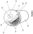
- the lid 100 which does not form part of the invention, is shown placed on the container 200.
- the portion 210 of the container 200 is also shown inserted in the open part or portion 130 of the lid. This allows the consumer to consume the content of the container with a natural flow and will therefore give a fully natural flow to the last drop.
- FIG 3 is a schematic side perspective sectional view of the lid 100 previously shown, and art of the container 200. The same reference signs are used.
- the open part 30 through which the top 120 of the container is inserted is clearly shown.
- the lid 100 is snapped on the top 210 of the container 200 by means of the seal 170 and the fastener 160.
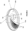
- Figure 4 depicts the underside or bottom view of the lid 100, which does not form part of the invention, showing the underside 120B of the the top 120 and the underside 140A of the wall.
- FIG 5a there is illustrated a side view of the container 200 and the lid 100 according to another embodiment herein.
- Figure 5b is a top view of the lid.
- the openings 150 are in the form of holes instead of slits.
- the lid 100 is attached to the container 200 and the fastener 160 secures the lid 100 to the container 200.
- the lid 100 acts as a seal 170 against the container 200, except for the open part 130, where the top 210 of the container 200 is exposed.
- the floor 140 has preferably, but not necessarily, openings at two different places, one close to the open part 130, where the mouth for drinking is placed, and the auxiliary opening 190, which can be placed on the adjacent side of the floor.
- the auxiliary opening 190 can be very small, acting as a "steam" hole 190, to level out pressure differences when beverage is passing the main openings 150.
- the auxiliary opening 190 may also act as an aroma vapor exit for the human nose.
- the floor 140 covers almost the whole horizontal container area 230, which means the open compartment 145 will be low so a human nose will fit into the open compartment 145, and hence a reduced angle of the container is necessary during drinking. This means that the leaning of the head backwards during drinking can be reduced, which will increase the comfort of drinking.
- the floor 140 is shaped to meet the wall 220 of the container 200 at the end of the floor 141.
- One embodiment of the invention solves the problem with a beverage in a container having a temperature that is higher than the the desired drinking temperature. With a beverage with a temperature as high as 95 degrees centigrade, cautions must be taken not to get burn. Usually, prior art has a sign "Caution contents hot", which obviously does only inform the consumer but does not solve the problem.
- the problem with hot beverages flushing may be solved having small openings 150 in the lid 100, where the openings will act as restriction of hot flow of beverage.
- the openings 150 are small to restrict flow of beverage, with typical total areas for said openings 150 between 3 to 50 mm 2 , preferably 5 to 15 mm 2 , and where the number of openings openings 150 is between 2 and 15, preferably between 2 and 5.
- compartment 145 formed between the floor 140 at the bottom of the lid, wall 120A of the lid, and the wall 220 of the container 200 at the partly open part 130 of the lid, where hot beverages can be collected, for sipping.
- the compartment is then below the top 210 of the container 200. This compartment is used to sip beverage, and hence obtain a comfortable temperature.
- an advantage with the embodiment described above is to reduce the flow rate of hot leverages entering the sipping compartment (142 or 145) of the lid using small openings. Flush of (hot) beverage is avoided. Note that even if slits are used instead of small holes (openings), this advantage is achieved as long as the width of the slits are small enough as previously described.
- a hot beverage can effectively and fast be cooled down to, for the person, an optimal temperature.
- the time for cooling depends on the beverage temperature in the container, the desired drinking temperature, the volume on the lid, the beverage area on the lid, the ambient temperature, and if and how the beverage is cooled by forced air flow from the mouth.
- the specific heat capacity at constant pressure, denoted c p for the beverage can be regarded constant, the same as for water 4190 J/kgK.
- the heat exchange can be approximated to 5 W/m 2 K, where the temperature difference is relative the ambient temperature. A faster cooling is obtained if the beverage is cooled by an air stream created by the mouth.
- ambient air will be mixed with the 37 centigrade breath.
- the mixed temperature is dependent on the flow and the distance to the object.
- the cooling temperature can therefore easily be regulated by the drinker.
- an approximate temperature of 30 centigrade can be used for cooling estimations.
- the heat exchange can be estimated by the convective heat transfer coefficient which is estimated to up to 25 W/m 2 K.
- the cooling effectivity is much higher than natural convection.
- a forced cooling is approximately 4.5 times more effective.
- the forced cooling is much more efficient, estimated here to 4.2 times, which is in accordance with experimental data.
- the cooling time can easily be controlled by the person itself.
- a 95 centigrade beverage can be cooled to 65 centigrade within 5 to 10 seconds for 5 ml, just by blowing on the lid.
- the cooling of the beverage will follow the mathematics of differential equations.
- the differential equation is rather complex, depending on temperature, and hence time dependent heat flux is present.
- the heat fluxes are:
- h c (t) is the convective heat transfer coefficient
- A the one sided cooling area
- T bevereage_lid (t) the beverage temperature on the lid
- T air (t) the temperature of the forced air flow
- T amb is the ambient air temperature
- F the air flow
- t the time.
- the cooling efficiency is mainly controlled by the air flow and the temperature of the beverage.
- T floor is the temperature of the floor in the compartment, which is dependent on the beverage temperature in the container.
- T T 0 * e ⁇ t/Tau
- Tau the time constant which approximately can be estimated by;
- Tau V * d * C p / h c * 0.5 T beverage + T drink ⁇ T air * A
- T drink is the wanted/desired drinking temperature, V the volume of beverage on the lid, and d the density of the beverage.
- Cooling the cooling area/minor compartment 142 is performed by tilting the container 200 and when the open compartment 145 on the lid is filled with beverage, the container 200 can then be tilted back and the beverage 330 will be drained back to the container 200 via openings 150 until the beverage reaches the top of a protrusion 146 (see figure 6a ) with openings 150.
- the peripheral openings 150 are towards to the wall 220 of the container.
- the beverage 350 (see figures 6d-6f ) that is left will then be trapped on the floor 142 at the minor compartment 142 of the lid 100, ready to cool down. Tilting the container 200 again will lead the cooled beverage 350 to the opening for drinking.
- a protrusion 146 on the floor 140 is provided, to hinder that beverage 350 is drain back to the container 200.
- the protrusion is provided with openings 150 over the floor level 140, but the openings under the top 210 of the container 200.
- a smaller amount of beverage 350 can be used on the floor of the lid by directing the beverage 350 on the lid 100 to the auxiliary opening 190.
- the lid 100 with container 200 can be twisted after tilting, leaving the openings 150 on a higher level.
- the compartment 142 hence provide a way to control the temperature of the beverage, either by letting hot beverage to cool down on the surface of the compartment or by blowing air with the mouth onto the hot beverage on the compartment. This is comparable to cooling hot soup on a spoon.
- the compartment 142 thus enables some part or amount of the beverage to remain in the compartment during consumption.
- Figure 5c shows how the compartment 145 is filled with beverage 330 from the beverage 300 in the container 200, when it is tilted.
- the beverage 330 in the compartment 145 can comfortably be sipped at the top 210 of the container 200. Note here that there is no protrusion 146.
- figures 6a-c show other embodiments of the lid 100 for low flow rate.
- a protrusion 146 including the openings 150 for the beverage to pass Figure 6a shows the protrusion 146 at a height d2 over the floor 140, where d2 is less than the height d1 from the floor to the top 210 of the container 200.
- the protrusion 146 enables or creates together with the floor 140 a minor compartment 142 within the compartment 145 for beverage 330.
- Figure 6b shows another embodiment where the openings 150 for beverage are within the upper part of the protrusion.
- Figure 6c shows an embodiment where the openings 150 for beverage is/are at the end 141b of the upper part of the protrusion 146 i.e. close to the wall of the beverage container when the lid is in place, which means all beverage 300 can be easily emptied from the container 200.
- the openings 150 are preferably positioned close to the wall 220 of the container e.g., between 0-3 mm, preferably 0-2 mm.
- Figures 6d-f show how the minor compartment 142 for cooling of the beverage 330 is filled.
- the container 200 has to be tilted at an angle large enough that the beverage pass the openings 150 in the protrusion 146 (see figure 6d ).
- the minor compartment 142 will start to fill.
- beverage 350 will drain back to the beverage 300 in the container 200, until the level reach the top of the protrusion 146 ( figure 6e ).
- a beverage volume 350 will be trapped in the minor compartment 142 ( figure 6f ).
- the beverage 350 in the minor compartment can easily be cooled down by the air flow from the drinker, which is a natural behavior, similar to cooling down soup on a spoon.
- the force and the time will define the cooling power.
- the trapped beverage 350 in the minor compartment can also be cooled down without forced air convection.
- the natural cooling convection by 5 W/m2K and radiation cooling will cool the trapped beverage, but at a slower rate.
- the container 200 is again tilted, the trapped and cooled beverage will enter the drinking area, mixed somewhat with the beverage 300 from the container 200.
- the height d2 of the protrusion 146 relative the height d1 from the floor 140 to the top 210 of the container 200, will control the mixing between cooled 350 and hot 300 beverage.
- Figures 7a-b show an embodiment where the minor compartment 142 for cooled beverage 350 leans toward the protrusion 146, letting the trapped beverage 350, still be trapped when the container 200 is placed horizontally ( figure 7b ).
- Figures 8a-b show an embodiment where the minor compartment 142 for cooled beverage 350 leans backwards from the protrusion 146, letting the trapped beverage 350 to be drained to the beverage 300 in the container 200 by means of the auxiliary opening 190, when the container 200 is placed horizontally ( figure 8b ).
- Figure 9a-9b show an embodiment where the minor compartment 142 for cooled beverage 350 is trapped by a protrusion wall 148, letting the trapped beverage to be trapped even if the container 200 is tilted somewhat from the horizontally position.
- the lid is provided with a protrusion wall 148 to isolate the minor compartment 142 from the auxiliary opening 190 of the lid 100.
- Figure 10a shows an embodiment of the lid 100 wherein has an oval form towards the open part or opening 130 against the wall of the container 200.
- the floor 140 extending more than the nominal radius dimension of the corresponding container, to enhance sealing at the edge 141 of the floor or protrusion. This will eliminate or reduce possible gaps between the floor 140 and the wall 220 if e.g. partial deformation and/or deviation from the container's nominal dimension is present and therefore a better sealing between the floor 140 and the wall 220 is achieved.
- the shape of the floor or protrusion is, as described, preferably somewhat oval at the edge 141. Because of the relatively larger dimension of the floor 140 at the edge 141, at the opening 130, the tightest fit between the lid 100 and the container 200 will likely be at the open part 130. Further, the openings 150 are an open structure placed at the end position 141/141b (see figure 11a ) of the floor 140.
- Figure 10b shows the lid 100 with a protrusion 146 with openings 150 for beverage asymmetrically positioned relative the open part 130 of the lid 100. This means that a larger volume of beverage 350 can be trapped on the lid 100.
- the openings in embodiments of the present invention provide restriction to particles, if any, contained in the beverage to be consumed such as coffee grains.
- Figure 11a-b shows a lid where the fastener 160 comprises a ridge 165 to enhance the fit of the edge 141 or 141b of the floor or protrusion respectively.
- the ridge 165 will snap under the top 210 of the container 200 making a safer attachment of the lid 100 and enable a better sealing of the edge of the floor or protrusion 141/141b.
- the ridge 165 at the fastener has preferably smaller dimensions towards the end 135 of the part 130 of the lid 100, to enable easier attachment of the lid 100, and to reduce stress of the material when the lid 100 is inserted or taken off the upper part 210 of the container 200.
- the ridge 165 can displace only a part of the open part 130 of the lid 100.
- the ridge 165 is placed inwards on the fastener at the open position of the lid 100, means that the fastener will squeeze tightly to the outside of the container's wall.
- the ridge 165 has two functions, 1) ensure that the container's wall will not flex from its nominal position, which could lead to a gap between the floor of the lid inside the container and the container's wall.
- nominal position or dimension means the geometrical dimensions for the container without any deformation, due to stress or other factors, i.e. a circular container assumes to be circular.
- the container will to some extent be deformed, either by forces or by its production process, e.g.
- the circular shape can be somewhat oval, 2) ensure that the fastener is hold in place under the rim of the container to ensure save attachment of the lid. Because there is no material above the fastener, the fastener is more prone to flex at this position, which could lead to an unsecure fit of the lid. However, the ridge will grab under the rim, safely position the lid on the right position with little risk that the fastener will slip over the rim.
- the lid 100 is also shown having a smaller depth 167 at the end of the ridge 165.
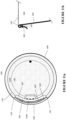
- Figure 12a shows a smooth transition 168 between the fastener 160 and the top 120 of the lid 100 to reduce material stress when the lid 100 is inserted or taken off.
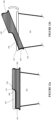
- Figure 12b shows how the fastener 160 of the lid is inserted under the top 120 of the container 200 during attachment of the lid 100 to the container 100. Because the lid 100 has an open structure 130, the lid 100 and the container 200 will flex during insertion of the lid 100, reducing the insertion force, but no flex is possible when the lid is inserted figure 12a , because the fastener 160 surrounds the container 200. Because of the natural flex and a low insertion force, a stiffer fastener 160 can be used, and hence a more secure attachment of the lid 100 to the container 200 is possible.
- Figure 13 shows another embodiment, where an auxiliary lid 400 is provided to be placed on the lid 100 to reduce the risk for spillage of beverage during transportation.
- the auxiliary lid 400 will further help insulation and slow down cooling of the beverage in the container.
- the (main) lid 100 is equipped with a concave portion 169 on the fastener 160 to meet a convex portion 450 on the auxiliary lid 400.
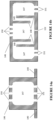
- Figure 14a shows the protrusion 146 acting also as a splash guard by incorporating a cavity 147 between outlet openings 150 and inlet openings 152 from the underside. If beverage is forced toward the lower openings 151, flow will be restricted and slowly fill the cavity 147. Any forced flow will be damped in the cavity. The small openings 150/151 and the cavity 147, will act as a (fluidistic) low pass filter. As shown, the openings 150 are connected to the cavity which is provided with openings for the inner part of the container where the beverage is stored.
- Figure 14b shows a more effective splash guard by incorporating restrictions 150/151 and cavities 147 in series, with an intermediate restriction 149 between the cavities 147.
- the intermediate restrictions have vertical channels which mean that the first cavity 147 has to be full before the next cavity 147 is filled. Intermediate cavities can be drained by a little opening 152, not to be saturated with beverage.
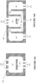
- Figure 14c-d shows another example of protrusion 146 including the cavity 147.
- the cavity 147 comprises at least one splash guard 153 to hinder injected beverage from lower openings 151, 152 to propagate out of the protrusion.
- Each cavity 147 is shown comprising a connection 149 formed by at least protrusion wall 148 in order to isolate the compartment 142 from the auxiliary opening 190 of the lid 100.
- the protrusion 146 is shown provided with a series of cavities divided by the connection 149 created by the walls 148.
- the openings 150 are attached or connected to the cavity(ies) 147.
- Figure 14e-f show another example of a splash guard that can be produced by vertical tooling, creating a wedge shaped cavity 147 in the protrusion 46.
- Figure 15a shows a sharp edge 105 of the lid 100 preferably at the open part 130 to create a better seal between the lid 100 and the container 200.
- the sharp edge 105 creates a higher sealing pressure between the lid and the container 200 or container wall 220.
- Figure 15b shown another example of the edge 105 which is flexible. Also in this case the flexible edge 105 creates a better seal between the lid 100 and the container 200 and a higher sealing pressure between the lid and the container 200 or container wall 220.
- the lid 100 comprises an auxiliary opening 190.
- a lid 192 is provided over the opening 190 as shown in figures 16a-16c .
- Such a lid 192 hinder beverage to be rejected (or injected upwards) at movement of the container or when the container squeezed.
- the lid 192 may be attached to the floor 140 of the lid 100 by posts 194.
- Figure 16b shows the lid 192 being equipped with walls (or a tube) 180 to be introduced in the auxiliary opening 190.
- Figure 16c shows a dome shaped lid 192, and figure 16d shown an upper view of the lid 192 and the post 194.
- the container could have any shape, square, oval, etc.
Landscapes
- Engineering & Computer Science (AREA)
- Mechanical Engineering (AREA)
- Closures For Containers (AREA)
- Table Devices Or Equipment (AREA)
Description
- The present invention relates to the field of lids for beverage containers, in particular it relates to an improved disposable lid for beverage containers.
- Since the 1930's disposable lids for beverage containers have been in used. A disposable lid is defined as a low cost device to be attached on the top of a beverage container. Low cost in this aspect means a lid for a beverage container that can be disposed without any significant cost for the seller or buyer, regarding ordinary drinks, such as coffee, tea, soda, water, etc. The container is normally a paper cup, Styrofoam cup, or other cups and mugs.
- The primary function of a disposable lid for beverage containers is to prevent the beverage to unintentionally be spilled. The first lids where just lids with no opening, which means that the lid had to be taken off before consuming consuming the content of the container, a process that could introduce spillage, especially if the environment is not still, such as in a car or other transportation means. For this reason, it has been a demand for disposable lids that do not need to be removed before drinking. One early solution was to peel off a part of the lid where the mouth was intended to meet the container as shown
US 4215793 A . However, this prior art lid has many advantages and problems. First, there is no restriction of the beverage flow which means that unnecessary large amount of hot beverages can unintentionally be consumed and burn the lips or mouth of the consumer. Also, the relatively large opening for the mouth is a risk for spill. Even during the peeling off of the removable part there is a risk for spillage of the content of the cup, due to the fact that there can be sudden movements during the peeling off. - To avoid problems with a large opening, a raised structure was developed with a lid that surrounds the container's rim, the lid comprising a raised part or an upwardly extended spout through which the contents of the cup is caused to flow as described and shown in
US 4345695 A . This spout, even if it is rather small, gives for hot beverages a stream of fluid that can easily burn the mouth. Moreover, the beverage has to be over the level of the cup's rim, which means there is a risk for spillage. Paper cups have almost always a seam that is not even, and hence is prone to leak if the beverage is over the top of the cup. A more catastrophic situation, which is not uncommon, is when the lid and cup separates, introducing a major leakage, which in case of a hot beverage, can be harmful. The spout can in some configurations be closed reducing the risk for spill during transportation, but the problem remains when the spout is in use during consumption of the contents of the container. A disposable lid according to the preamble of appendedclaim 1 is furthermore known fromFR 2 931 459 A1 - There are many problems to be solved for a disposable lid for a cup or container. One of the most important limitations is cost. It has to be cost efficient but still functional. The cost limitation often reduces the lid to be made of a polymer in one part. There are different issues that have to be addressed, and due to the cost limitation, all issues are difficult to solve in one solution. A choice of which problems to be solved must be prioritized. For non-disposable lids, the situation is different, where sophisticated and expensive solutions can be achieved. Packaging is also an issue that is not a property of the function, but of storage and transportation. To solve this, a cup lid is preferably stackable, leaving fewer options for functions. Properties to be solved is, leak proof during transportation, leak proof during drinking, leak proof after use if there are beverage residues etc.. One of the most inconvenient and dangerous hazards is the risk to be burned by hot beverages. Wanted properties can be to making coffee or tea directly in the cup, without letting the coffee grains or tea leaves to enter the mouth during drinking. For pleasure, it is important to have the right feel for the mouth and lips, preferably close to an open coffee cup and where aromas can flow freely to the nose. A preferable solution is where a person can sip, or rather slurp, mixing a hot beverage with cold air to reduce the risk for burn or uncomfortable heat.
- Coffee is typically made at 92 to 97 centigrade for best results. Drinking temperature for best aroma is typically 62 to 67 centigrade. A drinking temperature above 70 centigrade is uncomfortable and can be dangerous due to the risk of burns. Prior art of disposable lids cannot solve the listed problems with too hot beverages.
- In view of the shortcomings of prior art described above, the invention solves several problems and provide several features. These solutions and features are achieved by the lid as claimed in
claim 1 by a disposable lid for a container intended for beverage(s) comprising a seal and a fastener to be placed on the top of said container, the lid forming an open compartment wholly or partly inside said container, and said compartment is positioned below said top of said container, and where said compartment extends to the top of said seal, and said compartment is provided with a floor with a plurality of openings, enabling the beverage to pass through the openings, and the compartment is partly open to the wall of said container, when the lid is inserted, enabling a person's lips to be in contact with said top of said container during consumption of the beverage. The disposable lid further comprises a compartment above the floor, wherein the compartment enables some part of the beverage to remain in the compartment during consumption.; and wherein said floor is provided with a protrusion reaching above said compartment, but below said top of said container, and said protrusion comprises said openings for the beverage to pass. - The invention allows a natural feel of drinking beverages from a container, e.g. a cup or a mug, due to the open structure at the position where the mouth (or lips) meets the container. A common problem with leakage and spill at the interface between container and lid is eliminated due to the fact that the drinker of the beverage drinks directly at the top of the container, e.g. at the rim of a cup. Small openings of the compartment in the lid which is placed at the drinking position, reduces the free flow of liquid, reducing the risk of burn and heat from the beverage, and also reducing the spill upon rapid movement of the container. Another advantage is that the beverage level being under the rim of the container, is that it is leading to smaller angle of the container during drinking instead to the beverage reaching a level over the rim of the container and hence a larger angle of tilting the container is necessary.
- Preferred embodiments are defined by dependent claims 2 to 8. Long and closely spaces openings or slits, restricting particles contained in the coffee or tea such as coffee grains or tea leaves, to pass and hence acting as a permeable filter.
- According to the invention the protrusion in the floor of the compartment, but below the top of the container, allows the beverage to be trapped on the floor and hence be cooled down during the drinking process.
-
-
Figure 1 . Lid with slits, top-side view. -
Figure 2 . Lid with slits and container, top-side view. -
Figure 3 . Lid with slits and container, cross-section. -
Figure 4 . Lid with slits, bottom view. -
Figure 5a . Container with lid with openings, side view. -
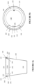
Figure 5b . Lid with openings top view. -
Figure 5c . Tilted container with lid with openings at bottom of lid, -
Figure 6a . Container with lid with openings in a protrusion, side view. -
Figure 6b , Lid with openings at top protrusion, top view. -
Figure 6c , Lid with openings at top edge of protrusion, top view. -
Figure 6d , Tilted container with lid with openings at protrusion, beverage reaching top of the container wall, side view. -
Figure 6e . Tilted container with lid with openings at protrusion, beverage reaching top of the protrusion, side view. -
Figure 6f . Container with lid with openings at protrusion, tilted back leaving beverage on the lid, side view. -
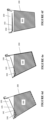
Figure 7a , Container with lid with openings and floor leaning towards the protrusion, and container tilted, side view. -
Figure 7b , Container with lid with openings and floor leaning towards the protrusion, and container placed horizontally, side view. -
Figure 8a . Container with lid with openings and floor leaning from the protrusion, and container tilted, side view. -
Figure 8b . Container with Lid with openings and floor leaning from the protrusion, and container placed horizontally, side view. -
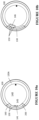
Figure 9a . Container with lid with openings and floor with a wall, side view. -
Figure 9b , Lid with openings and floor with a wall, top view. -
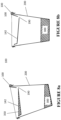
Figure 10a . Lid with an extended oval shaped floor. -
Figure 10b . Lid with an asymmetrical placed protrusion with openings, top view. -
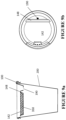
Figure 11a . Lid with a ridge on the fastener, top view. -
Figure 11b . Lid with a ridge on the fastener, side view. -
Figure 12a . Lid with a stress relief, side view. -
Figure 12b . Insertion of lid, side view. -
Figure 13 . Lid with an auxiliary lid or cover. -
Figure 14a . Protrusion in lid with a cavity. -
Figure 14b . Protrusion in lid with a series of cavities. -
Figure 14c . Protrusion in lid with a cavity and splash guard. -
Figure 14d . Protrusion in lid with a series of cavities and splash guard. -
Figure 14e . Protrusion in lid with a cavity with a draft for mold, front view. -
Figure 14f . Protrusion in lid with a cavity with a draft for mold, side view. -
Figure 15a . Sharp edge of lid against the container wall. -
Figure 15b . Flexible edge of lid against the container wall. -
Figure 16a . Lid/cover over auxiliary opening, side view. -
Figure 16b . Lid/cover over auxiliary opening, side view. -
Figure 16c . Domed lid/cover over auxiliary opening, side view. -
Figure 16d . Lid/cover over auxiliary opening, top view. - In the following, a detailed description of the exemplary embodiments is presented in conjunction with the drawings to enable easier understanding of the solutions(s) described herein.
- The invention discloses a disposable lid, which may be produced in one part. The lid may be made of multiple parts. The lid may be made of an environmentally friendly material, for example polymers, such as PLA (poly lactide acid or polylactide), PP (polypropylene), PS (polystyrene), PE (polyethylene), ABS (acrylonitride butadiene styrene) etc. The lid may be made by injection molding of polymers, but vacuum forming, and other methods may also be used.
- According to embodiments herein the lid comprises an open portion at the position for the mouth at the container, where the open portion, together with the wall of the container forms a compartment which is the place where beverage is ready for drinking. In one embodiment the compartment is occupying a part of the inner space of the container when placed on the contained, in another embodiment the compartment fills the whole or almost the whole inner area of the container. The drinking compartment can fill an arbitrary space inside the container. The less quantity of beverage in the container, the more the container has to be tilted for the beverage to reach the top of the container. At large tilting angles, the nose will be close to the inner part of the lid.
- The height of the compartment is chosen so the upper lip of the consumer can comfortably be placed inside the container during the drinking procedure. Therefore, the floor of the compartment is lower than the top or rim of the container. A suitable height is approximately 5 to 15 mm, preferably 7 to 13 mm. A too deep compartment will infringe on the beverage space, and hence reduce the amount of beverage that can be filled in the container.
- The floor of the compartment is equipped or provided with openings to allow the beverage to flow between the container and the compartment. One embodiment has a large area with small openings acting as a filter for particles such as coffee grains or tea leaves. The restrictions in the floor for that specific embodiment is primarily to hinder the particles, not the flow of beverage. According to another embodiment, the openings are small enough for reducing the flow of beverage, hence reducing the risk for burns and spill. The openings may have different forms as will be described in conjunction with some of the figures. According to another embodiment, there is provided another minor compartment inside the main compartment, described above, enabling beverage to be trapped and enabling a hot beverage too cool off. The invention is not limited by these embodiments.
- When drinking hot beverages, the drinking speed is naturally slow. The natural behavior is to "sip". The amount to sip is normally between 5 and 10 ml, smaller for hotter beverages. For a very fast drinker, a sip of 10 ml every 3 seconds, gives 1 minute to drink 2 dl. A more normal drinker takes a 5 ml sip every 15 seconds, which gives 10 minutes for 2 dl. This means that the flow rate of beverages passing the lid can be very slow without affecting the natural feeling of drinking.
- Referring to
Figure 1 there is illustrated a schematic top perspective view of a disposable lid which does not form part of the invention. The lid is suitable for beverage container(s) that may be acquired in coffee or tea shops and/or drink stores which sell carry-out drinks. Thelid 100 comprises anannular cover portion 110 for covering an opening at an open end or top or rim 210 (Figure 2 ) of acontainer 200. Thelid 100 maybe snapped on the top 210 of thecontainer 200 by means of aseal 170 and afastener 160. Theseal 170 may be defined as an outer peripheral edge of theannular cover portion 110 and thefastener 100 may be defined as a peripheral side wall portion disposed around the theseal 170. Thefastener 160 secures that thelid 100 is fixed to the top 210 of thecontainer 200 by having a smaller diameter than the top 210. Preferably thefastener 160 surrounds thecontainer 200, to securely ensure that thelid 100 is strongly attached to thecontainer 200. However, thefastener 160 does not necessarily have to surround the container. The part of thelid 100 that is on the top of thecontainer 210, i.e. theseal 170, is open 130 at a portion where a person drinks with the mouth. Theopening 130 may be viewed as a cut out portion of theseal 170 though which a portion of the top 210 of thecontainer 200 is introduced or inserted. This portion allows the consumer to have lips contact directly with thecontainer 200. - The
disposable lid 100 forms a compartment (see e.g., 145 infigure 5a or 5b ) provided with afloor 140 andopenings 150. Thefloor 140 is positioned below the top 120 of thelid 100, and hence below the top 210 of thecontainer 200 when in place. Theopenings 150 form slits extending radially towards awall 120A of thecompartment 145 orlid 100. The slits are narrow. Using narrow slits means that coffee grains will be hindered to pass the slits during consumption of the beverage. Using slits instead of holes means that there will be free passage for liquid between the grains even if coffee grains are stacked together. Because coffee grains can more or less clog the slits, a large filter area is preferable, e.g., preferably larger than 25% of the horizontal cross section area of thecontainer 200, but this is not a limit or a requirement. A useful slit width narrow typical openings between 0.1 mm to 0.5, mm preferable between 0.2 mm to 0.4 mm. - Preferably, the
slits 150 are distributed over an area, between 5% and 100% of said container's 200 horizontal area at saidfloor 140 portion, preferably larger than or equal to 20% of the horizontal top area of saidcontainer 200. Theslits 150 may be wedge-formed in the direction up to down, where the wedge ofslits 150 has the largest dimension upwards, and the wedge angles ofslits 150 is between 70 and 90 degrees, preferably between 75 and 85 degrees. - Preferably, when the lid is put on the
container 200, the slits are positioned at about 3 mm from thecontainer wall 200. Theslits 150 maybe an integrated art of thelid 100. - The
slits 150 can be created by ribs which are preferably connected to each other at certain distances, typically between 5 and 20 mm, for stability of the slit width, due to small dimensions. If the slits are not stabilized the ribs may bend with varying slit dimensions as a result. According to an example the connections between ribs are 8.5 mm, but this not a limit or requirement. As previously described thefloor 140 is connected to the top 120 of thelid 100 bywall 120A, and thelid 100 has anopening 130 where the lips touch therim 210 of thecontainer 200. The wall of thecontainer 200 act as a wall of thecompartment 145. - As shown in
figure 1 , thelid 100, which does not form part of the invention, may comprise anopening 190 formed by aprotrusion 180 or wall ortube 180 extending inwards thecontainer 200 for facilitating filling the beverage container with food additives e.g., hot water, sugar, coffee, tea, etc. Thelid 100, preferably, has thinner dimensions at edges making the material seal better at theopen part 130, or making the material flexible at theopen part 130 to enable better sealing. - As shown in
Figure 2 , thelid 100, which does not form part of the invention, is shown placed on thecontainer 200. Theportion 210 of thecontainer 200 is also shown inserted in the open part orportion 130 of the lid. This allows the consumer to consume the content of the container with a natural flow and will therefore give a fully natural flow to the last drop. -
Figure 3 is a schematic side perspective sectional view of thelid 100 previously shown, and art of thecontainer 200. The same reference signs are used. The open part 30 through which the top 120 of the container is inserted is clearly shown. Thelid 100 is snapped on the top 210 of thecontainer 200 by means of theseal 170 and thefastener 160. -
Figure 4 depicts the underside or bottom view of thelid 100, which does not form part of the invention, showing theunderside 120B of the the top 120 and theunderside 140A of the wall. - Referring to
figure 5a there is illustrated a side view of thecontainer 200 and thelid 100 according to another embodiment herein.Figure 5b is a top view of the lid. As shown theopenings 150 are in the form of holes instead of slits. Thelid 100 is attached to thecontainer 200 and thefastener 160 secures thelid 100 to thecontainer 200. Thelid 100 acts as aseal 170 against thecontainer 200, except for theopen part 130, where the top 210 of thecontainer 200 is exposed. - The
floor 140 has preferably, but not necessarily, openings at two different places, one close to theopen part 130, where the mouth for drinking is placed, and theauxiliary opening 190, which can be placed on the adjacent side of the floor. Theauxiliary opening 190 can be very small, acting as a "steam"hole 190, to level out pressure differences when beverage is passing themain openings 150. Theauxiliary opening 190 may also act as an aroma vapor exit for the human nose. In an example thefloor 140 covers almost the wholehorizontal container area 230, which means theopen compartment 145 will be low so a human nose will fit into theopen compartment 145, and hence a reduced angle of the container is necessary during drinking. This means that the leaning of the head backwards during drinking can be reduced, which will increase the comfort of drinking. - The
floor 140 is shaped to meet thewall 220 of thecontainer 200 at the end of thefloor 141. - One embodiment of the invention solves the problem with a beverage in a container having a temperature that is higher than the the desired drinking temperature. With a beverage with a temperature as high as 95 degrees centigrade, cautions must be taken not to get burn. Usually, prior art has a sign "Caution contents hot", which obviously does only inform the consumer but does not solve the problem. The problem with hot beverages flushing may be solved having
small openings 150 in thelid 100, where the openings will act as restriction of hot flow of beverage. Theopenings 150 are small to restrict flow of beverage, with typical total areas for saidopenings 150 between 3 to 50 mm2, preferably 5 to 15 mm2, and where the number ofopenings openings 150 is between 2 and 15, preferably between 2 and 5. By using multiple openings instead of one opening, leads to a higher restriction at higher flow rates, and will therefore restrict the beverage velocity, and hence reduce the risk for spill. The higher the velocity of the beverage passing through the openings, the higher the risk is for spill. A higher kinetic energy of the beverage will lead to a longer distance that the beverage may travel. With many small openings, the velocity of the beverage will be reduced, but the multiple openings will enable a wanted flowrate. By choosing dimensions of the openings and the number of openings, both beverage velocity and flow rate can be controlled as wanted. The principle is similar to a shower head, a large showerhead with many small holes will led to a small velocity of the fluid. - The problem with hot beverage during drinking is further solved by using
compartment 145 formed between thefloor 140 at the bottom of the lid,wall 120A of the lid, and thewall 220 of thecontainer 200 at the partlyopen part 130 of the lid, where hot beverages can be collected, for sipping. The compartment is then below the top 210 of thecontainer 200. This compartment is used to sip beverage, and hence obtain a comfortable temperature. - Hence, an advantage with the embodiment described above is to reduce the flow rate of hot leverages entering the sipping compartment (142 or 145) of the lid using small openings. Flush of (hot) beverage is avoided. Note that even if slits are used instead of small holes (openings), this advantage is achieved as long as the width of the slits are small enough as previously described.
- By using the
floor 140 of the lid as a cooling area, a hot beverage can effectively and fast be cooled down to, for the person, an optimal temperature. The time for cooling depends on the beverage temperature in the container, the desired drinking temperature, the volume on the lid, the beverage area on the lid, the ambient temperature, and if and how the beverage is cooled by forced air flow from the mouth. The specific heat capacity at constant pressure, denoted cp, for the beverage can be regarded constant, the same as for water 4190 J/kgK. For natural convection, the heat exchange can be approximated to 5 W/m2K, where the temperature difference is relative the ambient temperature. A faster cooling is obtained if the beverage is cooled by an air stream created by the mouth. Then ambient air will be mixed with the 37 centigrade breath. The mixed temperature is dependent on the flow and the distance to the object. The cooling temperature can therefore easily be regulated by the drinker. However, for simplicity, an approximate temperature of 30 centigrade can be used for cooling estimations. For a forced air stream, the heat exchange can be estimated by the convective heat transfer coefficient which is estimated to up to 25 W/m2K. Despite a somewhat hotter (30 centigrade) air stream, the cooling effectivity is much higher than natural convection. For a 95 centigrade beverage, 23 centigrade ambient temperature, a forced cooling is approximately 4.5 times more effective. Still at 65 centigrade, the forced cooling is much more efficient, estimated here to 4.2 times, which is in accordance with experimental data. - The cooling time can easily be controlled by the person itself. For a 9 cm diameter lid using 80% of the surface as a cooling surface, a 95 centigrade beverage can be cooled to 65 centigrade within 5 to 10 seconds for 5 ml, just by blowing on the lid.
- The floor where the hot beverage rests, will to some extent be heated by the hot beverage underneath. Experiments show that for a 95 centigrade beverage in a full container, the floor on the lid will reach a temperature of 50-60 centigrade, where the outside of an uninsulated container will reach 60-70 centigrade.
- The cooling of the beverage will follow the mathematics of differential equations. The differential equation is rather complex, depending on temperature, and hence time dependent heat flux is present. The heat fluxes are:
- Q0(Tbevereage_lid, F, Tair), convection
- Q1(Tbevereage_lid,Tamb), conduction to air
- Q2(Tbevereage_lid, Tamb), radiation
- Q3(Tbevereage_lid, Tfloor), conduction to floor
- Total heat flux Qtot is given by: Qtot = Q0 + Q1 + Q2 + Q3
- Where Q0 is the dominating term.
- Q0 is proportional to hc(t, F)∗A∗[Tbevereage_lid(t) - Tair(t)]
- Where hc(t), is the convective heat transfer coefficient, A, the one sided cooling area, Tbevereage_lid(t), the beverage temperature on the lid, Tair(t), the temperature of the forced air flow, Tamb is the ambient air temperature, F, the air flow, and t, the time. As can be seen, the cooling efficiency is mainly controlled by the air flow and the temperature of the beverage. Tfloor is the temperature of the floor in the compartment, which is dependent on the beverage temperature in the container.
- The temperature of the beverage on the cooling area can for simplicity be approximated with a first order differential equation:


- Filling the cooling area/minor compartment 142 (see
figure 6a-6f ) is performed by tilting thecontainer 200 and when theopen compartment 145 on the lid is filled with beverage, thecontainer 200 can then be tilted back and thebeverage 330 will be drained back to thecontainer 200 viaopenings 150 until the beverage reaches the top of a protrusion 146 (seefigure 6a ) withopenings 150. Theperipheral openings 150 are towards to thewall 220 of the container. The beverage 350 (seefigures 6d-6f ) that is left will then be trapped on thefloor 142 at theminor compartment 142 of thelid 100, ready to cool down. Tilting thecontainer 200 again will lead the cooledbeverage 350 to the opening for drinking. - To be able to fill the (minor)
compartment 142, aprotrusion 146 on thefloor 140 is provided, to hinder thatbeverage 350 is drain back to thecontainer 200. The protrusion is provided withopenings 150 over thefloor level 140, but the openings under the top 210 of thecontainer 200. - If the beverage 330 (
figure 6d ) is very hot a smaller amount of beverage 350 (figure 6e-6f ) can be used on the floor of the lid by directing thebeverage 350 on thelid 100 to theauxiliary opening 190. - If a larger amount of
beverage 350 on the floor 140 (or 142) is wanted, thelid 100 withcontainer 200 can be twisted after tilting, leaving theopenings 150 on a higher level. Another way to increase thebeverage 350 volume on theminor compartment 142, is to tilt the container back fast, which means that due to the restriction inopenings 150, thebeverage 350 will not be completely drain back to thecontainer 200, but be left on theminor compartment 142. - The
compartment 142 hence provide a way to control the temperature of the beverage, either by letting hot beverage to cool down on the surface of the compartment or by blowing air with the mouth onto the hot beverage on the compartment. This is comparable to cooling hot soup on a spoon. Thecompartment 142 thus enables some part or amount of the beverage to remain in the compartment during consumption. -
Figure 5c shows how thecompartment 145 is filled withbeverage 330 from thebeverage 300 in thecontainer 200, when it is tilted. Thebeverage 330 in thecompartment 145 can comfortably be sipped at the top 210 of thecontainer 200. Note here that there is noprotrusion 146. - To further improve the lid of
figure 5 ,figures 6a-c show other embodiments of thelid 100 for low flow rate. This is achieved by providing, as previously described, aprotrusion 146 including theopenings 150 for the beverage to pass.Figure 6a shows theprotrusion 146 at a height d2 over thefloor 140, where d2 is less than the height d1 from the floor to the top 210 of thecontainer 200. Theprotrusion 146 enables or creates together with the floor 140 aminor compartment 142 within thecompartment 145 forbeverage 330.Figure 6b shows another embodiment where theopenings 150 for beverage are within the upper part of the protrusion.Figure 6c shows an embodiment where theopenings 150 for beverage is/are at theend 141b of the upper part of theprotrusion 146 i.e. close to the wall of the beverage container when the lid is in place, which means allbeverage 300 can be easily emptied from thecontainer 200. When thelid 100 is inserted on thecontainer 200, theopenings 150 are preferably positioned close to thewall 220 of the container e.g., between 0-3 mm, preferably 0-2 mm. -
Figures 6d-f show how theminor compartment 142 for cooling of thebeverage 330 is filled. First, thecontainer 200 has to be tilted at an angle large enough that the beverage pass theopenings 150 in the protrusion 146 (seefigure 6d ). Then theminor compartment 142 will start to fill. When thecontainer 200 is tilted back,beverage 350 will drain back to thebeverage 300 in thecontainer 200, until the level reach the top of the protrusion 146 (figure 6e ). When thecontainer 200 is further tilted back, abeverage volume 350 will be trapped in the minor compartment 142 (figure 6f ). Thebeverage 350 in the minor compartment can easily be cooled down by the air flow from the drinker, which is a natural behavior, similar to cooling down soup on a spoon. The force and the time will define the cooling power. The trappedbeverage 350 in the minor compartment can also be cooled down without forced air convection. The natural cooling convection by 5 W/m2K and radiation cooling will cool the trapped beverage, but at a slower rate. When thecontainer 200 is again tilted, the trapped and cooled beverage will enter the drinking area, mixed somewhat with thebeverage 300 from thecontainer 200. The height d2 of theprotrusion 146 relative the height d1 from thefloor 140 to the top 210 of thecontainer 200, will control the mixing between cooled 350 and hot 300 beverage. The higher (distance d2) theprotrusion 146 is the lesshot beverage 300 will be mixed with the cooledbeverage 350. -
Figures 7a-b show an embodiment where theminor compartment 142 for cooledbeverage 350 leans toward theprotrusion 146, letting the trappedbeverage 350, still be trapped when thecontainer 200 is placed horizontally (figure 7b ). -
Figures 8a-b show an embodiment where theminor compartment 142 for cooledbeverage 350 leans backwards from theprotrusion 146, letting the trappedbeverage 350 to be drained to thebeverage 300 in thecontainer 200 by means of theauxiliary opening 190, when thecontainer 200 is placed horizontally (figure 8b ). -
Figure 9a-9b show an embodiment where theminor compartment 142 for cooledbeverage 350 is trapped by aprotrusion wall 148, letting the trapped beverage to be trapped even if thecontainer 200 is tilted somewhat from the horizontally position. Hence, the lid is provided with aprotrusion wall 148 to isolate theminor compartment 142 from theauxiliary opening 190 of thelid 100. -
Figure 10a shows an embodiment of thelid 100 wherein has an oval form towards the open part oropening 130 against the wall of thecontainer 200. Thefloor 140 extending more than the nominal radius dimension of the corresponding container, to enhance sealing at theedge 141 of the floor or protrusion. This will eliminate or reduce possible gaps between thefloor 140 and thewall 220 if e.g. partial deformation and/or deviation from the container's nominal dimension is present and therefore a better sealing between thefloor 140 and thewall 220 is achieved. The shape of the floor or protrusion is, as described, preferably somewhat oval at theedge 141. Because of the relatively larger dimension of thefloor 140 at theedge 141, at theopening 130, the tightest fit between thelid 100 and thecontainer 200 will likely be at theopen part 130. Further, theopenings 150 are an open structure placed at theend position 141/141b (seefigure 11a ) of thefloor 140. -
Figure 10b shows thelid 100 with aprotrusion 146 withopenings 150 for beverage asymmetrically positioned relative theopen part 130 of thelid 100. This means that a larger volume ofbeverage 350 can be trapped on thelid 100. The openings in embodiments of the present invention provide restriction to particles, if any, contained in the beverage to be consumed such as coffee grains. -
Figure 11a-b shows a lid where thefastener 160 comprises aridge 165 to enhance the fit of theedge ridge 165 will snap under the top 210 of thecontainer 200 making a safer attachment of thelid 100 and enable a better sealing of the edge of the floor orprotrusion 141/141b. Theridge 165 at the fastener has preferably smaller dimensions towards theend 135 of thepart 130 of thelid 100, to enable easier attachment of thelid 100, and to reduce stress of the material when thelid 100 is inserted or taken off theupper part 210 of thecontainer 200. Theridge 165 can displace only a part of theopen part 130 of thelid 100. - Hence, the
ridge 165 is placed inwards on the fastener at the open position of thelid 100, means that the fastener will squeeze tightly to the outside of the container's wall. Theridge 165 has two functions, 1) ensure that the container's wall will not flex from its nominal position, which could lead to a gap between the floor of the lid inside the container and the container's wall. With nominal position or dimension, means the geometrical dimensions for the container without any deformation, due to stress or other factors, i.e. a circular container assumes to be circular. However, generally the container will to some extent be deformed, either by forces or by its production process, e.g. the circular shape can be somewhat oval, 2) ensure that the fastener is hold in place under the rim of the container to ensure save attachment of the lid. Because there is no material above the fastener, the fastener is more prone to flex at this position, which could lead to an unsecure fit of the lid. However, the ridge will grab under the rim, safely position the lid on the right position with little risk that the fastener will slip over the rim. Thelid 100 is also shown having asmaller depth 167 at the end of theridge 165. -
Figure 12a shows asmooth transition 168 between thefastener 160 and the top 120 of thelid 100 to reduce material stress when thelid 100 is inserted or taken off.Figure 12b shows how thefastener 160 of the lid is inserted under the top 120 of thecontainer 200 during attachment of thelid 100 to thecontainer 100. Because thelid 100 has anopen structure 130, thelid 100 and thecontainer 200 will flex during insertion of thelid 100, reducing the insertion force, but no flex is possible when the lid is insertedfigure 12a , because thefastener 160 surrounds thecontainer 200. Because of the natural flex and a low insertion force, astiffer fastener 160 can be used, and hence a more secure attachment of thelid 100 to thecontainer 200 is possible. - It should be mentioned that a fastener that squeezes the outside of the container's wall will increase the force to remove the lid from the container. Most containers are circular shaped with a rim on top, which means that a fastener snapped at the upper part of the wall under the rim will be more safely attached. When the fastener completely surrounds the circumference, i.e. the fastener is circular, the attachment is further enhanced. Because the invention incorporates an open part at the drinking position at the container's rim, the fastener can be thread on at this position, where the lid is placed at an angle, e.g. 20 to 60 degrees, with the fastener under the rim, and then fold down (as shown in
figure 12b ) with a "click". Because the container can flex when the lid is not on, the force to thread on the lid at an angle will be rather small, and when the fastener on the open part is in place under the rim, the lid is easily snapped on the rim. -
Figure 13 shows another embodiment, where anauxiliary lid 400 is provided to be placed on thelid 100 to reduce the risk for spillage of beverage during transportation. Theauxiliary lid 400 will further help insulation and slow down cooling of the beverage in the container. The (main)lid 100 is equipped with aconcave portion 169 on thefastener 160 to meet aconvex portion 450 on theauxiliary lid 400. -
Figure 14a shows theprotrusion 146 acting also as a splash guard by incorporating acavity 147 betweenoutlet openings 150 andinlet openings 152 from the underside. If beverage is forced toward thelower openings 151, flow will be restricted and slowly fill thecavity 147. Any forced flow will be damped in the cavity. Thesmall openings 150/151 and thecavity 147, will act as a (fluidistic) low pass filter. As shown, theopenings 150 are connected to the cavity which is provided with openings for the inner part of the container where the beverage is stored. -
Figure 14b shows a more effective splash guard by incorporatingrestrictions 150/151 andcavities 147 in series, with anintermediate restriction 149 between thecavities 147. The intermediate restrictions have vertical channels which mean that thefirst cavity 147 has to be full before thenext cavity 147 is filled. Intermediate cavities can be drained by alittle opening 152, not to be saturated with beverage. -
Figure 14c-d shows another example ofprotrusion 146 including thecavity 147. As shown, thecavity 147 comprises at least onesplash guard 153 to hinder injected beverage fromlower openings - Each
cavity 147 is shown comprising aconnection 149 formed by at leastprotrusion wall 148 in order to isolate thecompartment 142 from theauxiliary opening 190 of thelid 100. InFigure 14d , theprotrusion 146 is shown provided with a series of cavities divided by theconnection 149 created by thewalls 148. Theopenings 150, previously described, are attached or connected to the cavity(ies) 147. -
Figure 14e-f show another example of a splash guard that can be produced by vertical tooling, creating a wedge shapedcavity 147 in the protrusion 46. -
Figure 15a shows asharp edge 105 of thelid 100 preferably at theopen part 130 to create a better seal between thelid 100 and thecontainer 200. Thesharp edge 105 creates a higher sealing pressure between the lid and thecontainer 200 orcontainer wall 220. -
Figure 15b shown another example of theedge 105 which is flexible. Also in this case theflexible edge 105 creates a better seal between thelid 100 and thecontainer 200 and a higher sealing pressure between the lid and thecontainer 200 orcontainer wall 220. - As previously described, the
lid 100 comprises anauxiliary opening 190. In this example, alid 192 is provided over theopening 190 as shown infigures 16a-16c . Such alid 192 hinder beverage to be rejected (or injected upwards) at movement of the container or when the container squeezed. Thelid 192 may be attached to thefloor 140 of thelid 100 byposts 194. -
Figure 16b shows thelid 192 being equipped with walls (or a tube) 180 to be introduced in theauxiliary opening 190.Figure 16c shows a dome shapedlid 192, andfigure 16d shown an upper view of thelid 192 and thepost 194. - The previously described embodiments provide many advantages and features which include:
- Enabling natural sipping from the container, e.g. flow of small amount of beverage can easily be controlled by the drinking person, and by blowing with the mouth, hot beverage can be cooled off with cold air, which is the natural way to drink not beverages.
- Reducing the flow rate of hot beverage entering the sipping compartment of the lid/container using small openings. No flush of hot beverage is then possible.
- No leakage of beverage between the lid and the container, because there is no seal the beverage has to pass by during drinking.
- No leakage of beverage if the lid and the container separate, due to the fact that drinking is only performed directly to the container.
- Low insertion force of the lid, but secure attachment due to a ridge on the fastener and an open part on the lid.
- Secure attachment of the lid because a stiffer fastener can be used because the structure enables a low insertion force.
- Possibility to use the minor compartment in the lid to control the temperature, either by letting the hot beverage cool at the surface, or more effectively by blowing air with the mouth onto the hot beverage on the minor compartment, like the natural thing to cool hot soup on a spoon. The temperature reduction is easily controlled by time and blowing force.
- Openings placed at the end of the lid's floor enables all beverage to be consumed, no beverage has to be trapped in the container.
- The invention's structure enables a splash proof solution, where beverage cannot splash through the openings due to hydrodynamic low pass filter for the beverage outlet. a small "steam hole" and
- Splash proof auxiliary opening by using a lid to stop splashes.
- Almost leakage proof solution with an auxiliary simple lid without openings that is temporarily attached over the main lid during transportation.
- An auxiliary lid not only eliminates spill during transportation, but also increases the insulation, which keep the temperature of the beverage for a longer time.
- An extra lid over the auxiliary opening to reduce to hinder ejection of the beverage during (sudden) movement of the container or when the container is squeezed.
- Additional advantages and features of the embodiments herein have already been described and need not be repeated.
- The invention is not limited by the embodiments shown and is defined by the appended set of claims. For instance, the container could have any shape, square, oval, etc.
Claims (8)
- A disposable lid (100) for a container (200) intended for a beverage (300), comprising:- a seal (170), and a fastener (160) to be placed under the top (210) of the container (200) to enable attachment of the lid (100) to said container (200);- said lid (100) forming an open compartment (145) wholly or partly inside the container (200) when placed on the container, wherein- the compartment (145), when in place, is positioned below said top (210) of said container (200), and- wherein said compartment (145) extends to the top of said seal (170), and- said compartment (145) is provided with a floor (140) comprising a plurality of openings (150), enabling said beverage (300) to pass through the openings (150), and- wherein the compartment is partly open (130) to the wall (220) of said container (200) when the lid (100) is inserted, enabling a person's lips to be in contact with said top (210) of said container (200) during consumption of the beverage (300);- characterized in that:- the disposable lid (100) further comprises a compartment (142) above the floor (140), wherein the compartment (142) enables some part of the beverage (300) to remain in the compartment (142) during consumption; and- wherein said floor (140) is provided with a protrusion (146) reaching above said compartment (142), but below said top (210) of said container (200), and said protrusion (146) comprises said openings (150) for the beverage to pass.
- The disposable lid (100) according to claim 1, wherein said fastener (160) surrounds the outside at the upper part of the wall (220) of said container (200) below the container's top (210).
- The disposable lid (100) according to claim 1 or claim 2, wherein said floor (140) partly extends longer than the nominal radius of said container (200) at said floor (140), at the position (141) of said partly open part of said lid, without said lid (100) inserted.
- The disposable lid (100) according to anyone of claims 1 to 3, wherein said floor (140) has an oval (141) form towards said opening (130) against the wall of said container (200).
- The disposable lid (100) according to anyone of claims 1 to 4, wherein the plurality of openings (150) provide restriction to particles, if any, contained in the beverage to be consumed such as coffee grains.
- The disposable lid (100) according to anyone of claims 1-5 wherein the plurality of openings (150), when the lid (100) is in place, are positioned at a distance from the wall (220), between 0 to 3 mm, preferably between 0 to 2 mm.
- The disposable lid (100) according to anyone of claims 1-6 wherein the plurality of openings (150) are an integrated part of the lid (100).
- The disposable lid (100) according to anyone of claims 1-7 wherein the openings (150) are small to restrict flow of beverage, with typical total areas for said openings (150) between 3 to 50 mm2, preferably 5 to 15 mm2.
Applications Claiming Priority (2)
| Application Number | Priority Date | Filing Date | Title |
|---|---|---|---|
| SE1750119A SE540423C2 (en) | 2017-02-08 | 2017-02-08 | A disposable lid for beverage containers |
| PCT/SE2018/050071 WO2018147783A1 (en) | 2017-02-08 | 2018-01-31 | A disposable lid for beverage containers |
Publications (3)
| Publication Number | Publication Date |
|---|---|
| EP3580136A1 EP3580136A1 (en) | 2019-12-18 |
| EP3580136A4 EP3580136A4 (en) | 2020-12-23 |
| EP3580136B1 true EP3580136B1 (en) | 2023-08-02 |
Family
ID=63106954
Family Applications (1)
| Application Number | Title | Priority Date | Filing Date |
|---|---|---|---|
| EP18751815.4A Active EP3580136B1 (en) | 2017-02-08 | 2018-01-31 | A disposable lid for beverage containers |
Country Status (10)
| Country | Link |
|---|---|
| US (1) | US10906707B2 (en) |
| EP (1) | EP3580136B1 (en) |
| JP (1) | JP7178760B2 (en) |
| CN (1) | CN110035956B (en) |
| DK (1) | DK3580136T3 (en) |
| ES (1) | ES2959936T3 (en) |
| FI (1) | FI3580136T3 (en) |
| PL (1) | PL3580136T3 (en) |
| SE (1) | SE540423C2 (en) |
| WO (1) | WO2018147783A1 (en) |
Families Citing this family (4)
| Publication number | Priority date | Publication date | Assignee | Title |
|---|---|---|---|---|
| USD847571S1 (en) * | 2017-03-13 | 2019-05-07 | Global Advantage Trading and Imports, LLC | Beverage container |
| USD943345S1 (en) * | 2019-07-17 | 2022-02-15 | Unicup Scandinavia Ab | Lid for drinking vessels |
| US20220313003A1 (en) * | 2021-04-01 | 2022-10-06 | Tierra Del Mate LLC | Mate tea lid |
| CN221273986U (en) * | 2023-11-29 | 2024-07-05 | 黄婵胜 | Cap for beverage container |
Citations (1)
| Publication number | Priority date | Publication date | Assignee | Title |
|---|---|---|---|---|
| FR2931459A1 (en) * | 2008-05-26 | 2009-11-27 | Thibault Detender | Drinking glass type container closing device, has walls extending transversely at periphery of disk in order to form recess, where recess forms fixation unit at interior of drinking glass type container |
Family Cites Families (19)
| Publication number | Priority date | Publication date | Assignee | Title |
|---|---|---|---|---|
| US2106453A (en) * | 1935-03-27 | 1938-01-25 | Sefco Inc | Portable strainer for insertion in the mouths of liquid containers |
| US3938695A (en) * | 1974-01-18 | 1976-02-17 | Stanley Ruff | Drink-through slosh-inhibiting closure lids for potable open-top containers |
| JPS5470745U (en) * | 1977-10-22 | 1979-05-19 | ||
| US4202459A (en) * | 1978-08-25 | 1980-05-13 | Billitzer Edward P | Disposable cup cover |
| US4215793A (en) | 1978-11-29 | 1980-08-05 | George Packard | Anti-spill lid |
| US4345695A (en) | 1980-05-01 | 1982-08-24 | Galloway James V | Lid for a drinking cup |
| US7275652B2 (en) * | 2003-10-07 | 2007-10-02 | Morris Jeffrey M | Cup lid apparatus |
| US20060249521A1 (en) * | 2004-04-15 | 2006-11-09 | Dark Richard C G | Spill-resistant container |
| US8033420B2 (en) * | 2006-11-28 | 2011-10-11 | Htss Capital Llc | Anti-splash device for a beverage container |
| US7959029B2 (en) | 2007-01-12 | 2011-06-14 | Aslan Guild, Llc | Splash and spill resistant insulating lid |
| US20090108006A1 (en) * | 2007-10-26 | 2009-04-30 | Coollid Corporation | Beverage container lid having liquid cooling effect |
| WO2010071790A1 (en) * | 2008-12-16 | 2010-06-24 | Waddington North America, Inc. | One-piece splash and spill resistant lid |
| AU2012213387B2 (en) | 2011-02-02 | 2017-01-19 | Donna-marie SABGA | Drinking vessels |
| US20150201777A1 (en) * | 2012-02-17 | 2015-07-23 | K&Lab Co., Ltd. | Cup lid and portable protection case therefor |
| HRP20170870T1 (en) * | 2012-07-17 | 2017-08-25 | Cleveland Benedict Crudgington | SINGLE COVER FLOWER RESISTANT COVER |
| CN103960936A (en) * | 2013-01-28 | 2014-08-06 | 清新科技股份有限公司 | Disposable cup cover |
| WO2016115176A1 (en) * | 2015-01-16 | 2016-07-21 | Pavel Savenok | Container lid and damming insert constructions |
| US9840364B2 (en) * | 2014-01-16 | 2017-12-12 | Pavel Savenok | Container lid and damming insert constructions |
| CN106659318A (en) * | 2014-06-10 | 2017-05-10 | 梅丽莎·安妮特·布格达诺斯 | Disposable brewing container and lid |
-
2017
- 2017-02-08 SE SE1750119A patent/SE540423C2/en unknown
-
2018
- 2018-01-31 FI FIEP18751815.4T patent/FI3580136T3/en active
- 2018-01-31 WO PCT/SE2018/050071 patent/WO2018147783A1/en not_active Ceased
- 2018-01-31 DK DK18751815.4T patent/DK3580136T3/en active
- 2018-01-31 CN CN201880004792.6A patent/CN110035956B/en active Active
- 2018-01-31 PL PL18751815.4T patent/PL3580136T3/en unknown
- 2018-01-31 JP JP2018569159A patent/JP7178760B2/en active Active
- 2018-01-31 ES ES18751815T patent/ES2959936T3/en active Active
- 2018-01-31 EP EP18751815.4A patent/EP3580136B1/en active Active
- 2018-01-31 US US16/314,211 patent/US10906707B2/en active Active
Patent Citations (1)
| Publication number | Priority date | Publication date | Assignee | Title |
|---|---|---|---|---|
| FR2931459A1 (en) * | 2008-05-26 | 2009-11-27 | Thibault Detender | Drinking glass type container closing device, has walls extending transversely at periphery of disk in order to form recess, where recess forms fixation unit at interior of drinking glass type container |
Also Published As
| Publication number | Publication date |
|---|---|
| JP2020507520A (en) | 2020-03-12 |
| ES2959936T3 (en) | 2024-02-29 |
| DK3580136T3 (en) | 2023-10-23 |
| EP3580136A4 (en) | 2020-12-23 |
| US20190217997A1 (en) | 2019-07-18 |
| SE1750119A1 (en) | 2018-08-09 |
| SE540423C2 (en) | 2018-09-11 |
| EP3580136A1 (en) | 2019-12-18 |
| WO2018147783A1 (en) | 2018-08-16 |
| US10906707B2 (en) | 2021-02-02 |
| FI3580136T3 (en) | 2023-10-31 |
| CN110035956A (en) | 2019-07-19 |
| CN110035956B (en) | 2020-10-09 |
| PL3580136T3 (en) | 2023-12-27 |
| JP7178760B2 (en) | 2022-11-28 |
Similar Documents
| Publication | Publication Date | Title |
|---|---|---|
| US11297963B2 (en) | Lid for container | |
| US11136172B2 (en) | Lid for container | |
| US10863841B2 (en) | Spill prevention system for drinking cup | |
| CA3002463C (en) | Beverage lid for enhanced olfactory experience | |
| US4767019A (en) | Splash resistant cup lid | |
| CA2521063C (en) | Single-dose plastic capsule for powdered coffee and the like | |
| CN104220340B (en) | Lids and vapor guide baffles for beverage containers | |
| US20100163568A1 (en) | Single-use leak/spill prevention container lid and disposable container | |
| US5065880A (en) | Splash resistant cup lid | |
| US10906707B2 (en) | Disposable lid for beverage containers | |
| EP2470437B1 (en) | A lid, cup including a lid, and a method for forming a lid | |
| US20100133272A1 (en) | One-piece splash and spill resistant lid | |
| CN104411595B (en) | Splash Resistant Disposable Travel Lid | |
| WO2010027365A1 (en) | Single-use, leak/spill prevention container lid and disposable container | |
| CA2949166C (en) | Lid for container |
Legal Events
| Date | Code | Title | Description |
|---|---|---|---|
| STAA | Information on the status of an ep patent application or granted ep patent |
Free format text: STATUS: THE INTERNATIONAL PUBLICATION HAS BEEN MADE |
|
| PUAI | Public reference made under article 153(3) epc to a published international application that has entered the european phase |
Free format text: ORIGINAL CODE: 0009012 |
|
| STAA | Information on the status of an ep patent application or granted ep patent |
Free format text: STATUS: REQUEST FOR EXAMINATION WAS MADE |
|
| 17P | Request for examination filed |
Effective date: 20190829 |
|
| AK | Designated contracting states |
Kind code of ref document: A1 Designated state(s): AL AT BE BG CH CY CZ DE DK EE ES FI FR GB GR HR HU IE IS IT LI LT LU LV MC MK MT NL NO PL PT RO RS SE SI SK SM TR |
|
| AX | Request for extension of the european patent |
Extension state: BA ME |
|
| DAV | Request for validation of the european patent (deleted) | ||
| DAX | Request for extension of the european patent (deleted) | ||
| A4 | Supplementary search report drawn up and despatched |
Effective date: 20201120 |
|
| RIC1 | Information provided on ipc code assigned before grant |
Ipc: B65D 47/04 20060101ALI20201116BHEP Ipc: B65D 47/06 20060101ALI20201116BHEP Ipc: B65D 43/02 20060101AFI20201116BHEP |
|
| STAA | Information on the status of an ep patent application or granted ep patent |
Free format text: STATUS: EXAMINATION IS IN PROGRESS |
|
| 17Q | First examination report despatched |
Effective date: 20220718 |
|
| RAP3 | Party data changed (applicant data changed or rights of an application transferred) |
Owner name: LIPLID AB |
|
| GRAP | Despatch of communication of intention to grant a patent |
Free format text: ORIGINAL CODE: EPIDOSNIGR1 |
|
| STAA | Information on the status of an ep patent application or granted ep patent |
Free format text: STATUS: GRANT OF PATENT IS INTENDED |
|
| INTG | Intention to grant announced |
Effective date: 20230413 |
|
| GRAS | Grant fee paid |
Free format text: ORIGINAL CODE: EPIDOSNIGR3 |
|
| GRAA | (expected) grant |
Free format text: ORIGINAL CODE: 0009210 |
|
| STAA | Information on the status of an ep patent application or granted ep patent |
Free format text: STATUS: THE PATENT HAS BEEN GRANTED |
|
| P01 | Opt-out of the competence of the unified patent court (upc) registered |
Effective date: 20230616 |
|
| AK | Designated contracting states |
Kind code of ref document: B1 Designated state(s): AL AT BE BG CH CY CZ DE DK EE ES FI FR GB GR HR HU IE IS IT LI LT LU LV MC MK MT NL NO PL PT RO RS SE SI SK SM TR |
|
| REG | Reference to a national code |
Ref country code: GB Ref legal event code: FG4D |
|
| REG | Reference to a national code |
Ref country code: CH Ref legal event code: EP |
|
| REG | Reference to a national code |
Ref country code: DE Ref legal event code: R096 Ref document number: 602018054549 Country of ref document: DE |
|
| REG | Reference to a national code |
Ref country code: IE Ref legal event code: FG4D |
|
| REG | Reference to a national code |
Ref country code: DK Ref legal event code: T3 Effective date: 20231020 |
|
| REG | Reference to a national code |
Ref country code: NO Ref legal event code: T2 Effective date: 20230802 |
|
| REG | Reference to a national code |
Ref country code: FI Ref legal event code: FGE |
|
| REG | Reference to a national code |
Ref country code: SE Ref legal event code: TRGR |
|
| REG | Reference to a national code |
Ref country code: LT Ref legal event code: MG9D |
|
| REG | Reference to a national code |
Ref country code: NL Ref legal event code: MP Effective date: 20230802 |
|
| REG | Reference to a national code |
Ref country code: AT Ref legal event code: MK05 Ref document number: 1594496 Country of ref document: AT Kind code of ref document: T Effective date: 20230802 |
|
| PG25 | Lapsed in a contracting state [announced via postgrant information from national office to epo] |
Ref country code: GR Free format text: LAPSE BECAUSE OF FAILURE TO SUBMIT A TRANSLATION OF THE DESCRIPTION OR TO PAY THE FEE WITHIN THE PRESCRIBED TIME-LIMIT Effective date: 20231103 |
|
| PG25 | Lapsed in a contracting state [announced via postgrant information from national office to epo] |
Ref country code: IS Free format text: LAPSE BECAUSE OF FAILURE TO SUBMIT A TRANSLATION OF THE DESCRIPTION OR TO PAY THE FEE WITHIN THE PRESCRIBED TIME-LIMIT Effective date: 20231202 |
|
| PG25 | Lapsed in a contracting state [announced via postgrant information from national office to epo] |
Ref country code: RS Free format text: LAPSE BECAUSE OF FAILURE TO SUBMIT A TRANSLATION OF THE DESCRIPTION OR TO PAY THE FEE WITHIN THE PRESCRIBED TIME-LIMIT Effective date: 20230802 Ref country code: PT Free format text: LAPSE BECAUSE OF FAILURE TO SUBMIT A TRANSLATION OF THE DESCRIPTION OR TO PAY THE FEE WITHIN THE PRESCRIBED TIME-LIMIT Effective date: 20231204 Ref country code: NL Free format text: LAPSE BECAUSE OF FAILURE TO SUBMIT A TRANSLATION OF THE DESCRIPTION OR TO PAY THE FEE WITHIN THE PRESCRIBED TIME-LIMIT Effective date: 20230802 Ref country code: LV Free format text: LAPSE BECAUSE OF FAILURE TO SUBMIT A TRANSLATION OF THE DESCRIPTION OR TO PAY THE FEE WITHIN THE PRESCRIBED TIME-LIMIT Effective date: 20230802 Ref country code: LT Free format text: LAPSE BECAUSE OF FAILURE TO SUBMIT A TRANSLATION OF THE DESCRIPTION OR TO PAY THE FEE WITHIN THE PRESCRIBED TIME-LIMIT Effective date: 20230802 Ref country code: IS Free format text: LAPSE BECAUSE OF FAILURE TO SUBMIT A TRANSLATION OF THE DESCRIPTION OR TO PAY THE FEE WITHIN THE PRESCRIBED TIME-LIMIT Effective date: 20231202 Ref country code: HR Free format text: LAPSE BECAUSE OF FAILURE TO SUBMIT A TRANSLATION OF THE DESCRIPTION OR TO PAY THE FEE WITHIN THE PRESCRIBED TIME-LIMIT Effective date: 20230802 Ref country code: GR Free format text: LAPSE BECAUSE OF FAILURE TO SUBMIT A TRANSLATION OF THE DESCRIPTION OR TO PAY THE FEE WITHIN THE PRESCRIBED TIME-LIMIT Effective date: 20231103 Ref country code: AT Free format text: LAPSE BECAUSE OF FAILURE TO SUBMIT A TRANSLATION OF THE DESCRIPTION OR TO PAY THE FEE WITHIN THE PRESCRIBED TIME-LIMIT Effective date: 20230802 |
|
| REG | Reference to a national code |
Ref country code: ES Ref legal event code: FG2A Ref document number: 2959936 Country of ref document: ES Kind code of ref document: T3 Effective date: 20240229 |
|
| PG25 | Lapsed in a contracting state [announced via postgrant information from national office to epo] |
Ref country code: SM Free format text: LAPSE BECAUSE OF FAILURE TO SUBMIT A TRANSLATION OF THE DESCRIPTION OR TO PAY THE FEE WITHIN THE PRESCRIBED TIME-LIMIT Effective date: 20230802 Ref country code: RO Free format text: LAPSE BECAUSE OF FAILURE TO SUBMIT A TRANSLATION OF THE DESCRIPTION OR TO PAY THE FEE WITHIN THE PRESCRIBED TIME-LIMIT Effective date: 20230802 Ref country code: EE Free format text: LAPSE BECAUSE OF FAILURE TO SUBMIT A TRANSLATION OF THE DESCRIPTION OR TO PAY THE FEE WITHIN THE PRESCRIBED TIME-LIMIT Effective date: 20230802 Ref country code: CZ Free format text: LAPSE BECAUSE OF FAILURE TO SUBMIT A TRANSLATION OF THE DESCRIPTION OR TO PAY THE FEE WITHIN THE PRESCRIBED TIME-LIMIT Effective date: 20230802 Ref country code: SK Free format text: LAPSE BECAUSE OF FAILURE TO SUBMIT A TRANSLATION OF THE DESCRIPTION OR TO PAY THE FEE WITHIN THE PRESCRIBED TIME-LIMIT Effective date: 20230802 |
|
| REG | Reference to a national code |
Ref country code: DE Ref legal event code: R097 Ref document number: 602018054549 Country of ref document: DE |
|
| PLBE | No opposition filed within time limit |
Free format text: ORIGINAL CODE: 0009261 |
|
| STAA | Information on the status of an ep patent application or granted ep patent |
Free format text: STATUS: NO OPPOSITION FILED WITHIN TIME LIMIT |
|
| 26N | No opposition filed |
Effective date: 20240503 |
|
| PG25 | Lapsed in a contracting state [announced via postgrant information from national office to epo] |
Ref country code: SI Free format text: LAPSE BECAUSE OF FAILURE TO SUBMIT A TRANSLATION OF THE DESCRIPTION OR TO PAY THE FEE WITHIN THE PRESCRIBED TIME-LIMIT Effective date: 20230802 |
|
| PG25 | Lapsed in a contracting state [announced via postgrant information from national office to epo] |
Ref country code: MC Free format text: LAPSE BECAUSE OF FAILURE TO SUBMIT A TRANSLATION OF THE DESCRIPTION OR TO PAY THE FEE WITHIN THE PRESCRIBED TIME-LIMIT Effective date: 20230802 |
|
| PG25 | Lapsed in a contracting state [announced via postgrant information from national office to epo] |
Ref country code: MC Free format text: LAPSE BECAUSE OF FAILURE TO SUBMIT A TRANSLATION OF THE DESCRIPTION OR TO PAY THE FEE WITHIN THE PRESCRIBED TIME-LIMIT Effective date: 20230802 |
|
| REG | Reference to a national code |
Ref country code: CH Ref legal event code: PL |
|
| PG25 | Lapsed in a contracting state [announced via postgrant information from national office to epo] |
Ref country code: LU Free format text: LAPSE BECAUSE OF NON-PAYMENT OF DUE FEES Effective date: 20240131 |
|
| PG25 | Lapsed in a contracting state [announced via postgrant information from national office to epo] |
Ref country code: LU Free format text: LAPSE BECAUSE OF NON-PAYMENT OF DUE FEES Effective date: 20240131 |
|
| PG25 | Lapsed in a contracting state [announced via postgrant information from national office to epo] |
Ref country code: BE Free format text: LAPSE BECAUSE OF NON-PAYMENT OF DUE FEES Effective date: 20240131 |
|
| PG25 | Lapsed in a contracting state [announced via postgrant information from national office to epo] |
Ref country code: CH Free format text: LAPSE BECAUSE OF NON-PAYMENT OF DUE FEES Effective date: 20240131 |
|
| PG25 | Lapsed in a contracting state [announced via postgrant information from national office to epo] |
Ref country code: CH Free format text: LAPSE BECAUSE OF NON-PAYMENT OF DUE FEES Effective date: 20240131 Ref country code: BE Free format text: LAPSE BECAUSE OF NON-PAYMENT OF DUE FEES Effective date: 20240131 |
|
| REG | Reference to a national code |
Ref country code: BE Ref legal event code: MM Effective date: 20240131 |
|
| PG25 | Lapsed in a contracting state [announced via postgrant information from national office to epo] |
Ref country code: BG Free format text: LAPSE BECAUSE OF FAILURE TO SUBMIT A TRANSLATION OF THE DESCRIPTION OR TO PAY THE FEE WITHIN THE PRESCRIBED TIME-LIMIT Effective date: 20230802 |
|
| PG25 | Lapsed in a contracting state [announced via postgrant information from national office to epo] |
Ref country code: BG Free format text: LAPSE BECAUSE OF FAILURE TO SUBMIT A TRANSLATION OF THE DESCRIPTION OR TO PAY THE FEE WITHIN THE PRESCRIBED TIME-LIMIT Effective date: 20230802 |
|
| PG25 | Lapsed in a contracting state [announced via postgrant information from national office to epo] |
Ref country code: IE Free format text: LAPSE BECAUSE OF NON-PAYMENT OF DUE FEES Effective date: 20240131 |
|
| PG25 | Lapsed in a contracting state [announced via postgrant information from national office to epo] |
Ref country code: IE Free format text: LAPSE BECAUSE OF NON-PAYMENT OF DUE FEES Effective date: 20240131 |
|
| PGFP | Annual fee paid to national office [announced via postgrant information from national office to epo] |
Ref country code: DE Payment date: 20250121 Year of fee payment: 8 |
|
| PGFP | Annual fee paid to national office [announced via postgrant information from national office to epo] |
Ref country code: IT Payment date: 20250122 Year of fee payment: 8 |
|
| PG25 | Lapsed in a contracting state [announced via postgrant information from national office to epo] |
Ref country code: CY Free format text: LAPSE BECAUSE OF FAILURE TO SUBMIT A TRANSLATION OF THE DESCRIPTION OR TO PAY THE FEE WITHIN THE PRESCRIBED TIME-LIMIT; INVALID AB INITIO Effective date: 20180131 |
|
| PG25 | Lapsed in a contracting state [announced via postgrant information from national office to epo] |
Ref country code: HU Free format text: LAPSE BECAUSE OF FAILURE TO SUBMIT A TRANSLATION OF THE DESCRIPTION OR TO PAY THE FEE WITHIN THE PRESCRIBED TIME-LIMIT; INVALID AB INITIO Effective date: 20180131 |
|
| PGFP | Annual fee paid to national office [announced via postgrant information from national office to epo] |
Ref country code: GB Payment date: 20251106 Year of fee payment: 9 |
|
| PGFP | Annual fee paid to national office [announced via postgrant information from national office to epo] |
Ref country code: NO Payment date: 20251110 Year of fee payment: 9 |
|
| PGFP | Annual fee paid to national office [announced via postgrant information from national office to epo] |
Ref country code: FI Payment date: 20251106 Year of fee payment: 9 Ref country code: DK Payment date: 20251106 Year of fee payment: 9 |
|
| PGFP | Annual fee paid to national office [announced via postgrant information from national office to epo] |
Ref country code: FR Payment date: 20251106 Year of fee payment: 9 |
|
| PGFP | Annual fee paid to national office [announced via postgrant information from national office to epo] |
Ref country code: SE Payment date: 20251106 Year of fee payment: 9 |
|
| PGFP | Annual fee paid to national office [announced via postgrant information from national office to epo] |
Ref country code: ES Payment date: 20260206 Year of fee payment: 9 |
|
| PGFP | Annual fee paid to national office [announced via postgrant information from national office to epo] |
Ref country code: TR Payment date: 20260102 Year of fee payment: 9 |
|
| PGFP | Annual fee paid to national office [announced via postgrant information from national office to epo] |
Ref country code: PL Payment date: 20260105 Year of fee payment: 9 |